JP6736276B2 - Display panel and display device - Google Patents
Display panel and display device Download PDFInfo
- Publication number
- JP6736276B2 JP6736276B2 JP2015188062A JP2015188062A JP6736276B2 JP 6736276 B2 JP6736276 B2 JP 6736276B2 JP 2015188062 A JP2015188062 A JP 2015188062A JP 2015188062 A JP2015188062 A JP 2015188062A JP 6736276 B2 JP6736276 B2 JP 6736276B2
- Authority
- JP
- Japan
- Prior art keywords
- power supply
- pixels
- sub
- pixel
- supply line
- Prior art date
- Legal status (The legal status is an assumption and is not a legal conclusion. Google has not performed a legal analysis and makes no representation as to the accuracy of the status listed.)
- Active
Links
Images


Classifications
-
- G—PHYSICS
- G09—EDUCATION; CRYPTOGRAPHY; DISPLAY; ADVERTISING; SEALS
- G09G—ARRANGEMENTS OR CIRCUITS FOR CONTROL OF INDICATING DEVICES USING STATIC MEANS TO PRESENT VARIABLE INFORMATION
- G09G3/00—Control arrangements or circuits, of interest only in connection with visual indicators other than cathode-ray tubes
- G09G3/20—Control arrangements or circuits, of interest only in connection with visual indicators other than cathode-ray tubes for presentation of an assembly of a number of characters, e.g. a page, by composing the assembly by combination of individual elements arranged in a matrix no fixed position being assigned to or needed to be assigned to the individual characters or partial characters
- G09G3/22—Control arrangements or circuits, of interest only in connection with visual indicators other than cathode-ray tubes for presentation of an assembly of a number of characters, e.g. a page, by composing the assembly by combination of individual elements arranged in a matrix no fixed position being assigned to or needed to be assigned to the individual characters or partial characters using controlled light sources
- G09G3/30—Control arrangements or circuits, of interest only in connection with visual indicators other than cathode-ray tubes for presentation of an assembly of a number of characters, e.g. a page, by composing the assembly by combination of individual elements arranged in a matrix no fixed position being assigned to or needed to be assigned to the individual characters or partial characters using controlled light sources using electroluminescent panels
- G09G3/32—Control arrangements or circuits, of interest only in connection with visual indicators other than cathode-ray tubes for presentation of an assembly of a number of characters, e.g. a page, by composing the assembly by combination of individual elements arranged in a matrix no fixed position being assigned to or needed to be assigned to the individual characters or partial characters using controlled light sources using electroluminescent panels semiconductive, e.g. using light-emitting diodes [LED]
- G09G3/3208—Control arrangements or circuits, of interest only in connection with visual indicators other than cathode-ray tubes for presentation of an assembly of a number of characters, e.g. a page, by composing the assembly by combination of individual elements arranged in a matrix no fixed position being assigned to or needed to be assigned to the individual characters or partial characters using controlled light sources using electroluminescent panels semiconductive, e.g. using light-emitting diodes [LED] organic, e.g. using organic light-emitting diodes [OLED]
- G09G3/3225—Control arrangements or circuits, of interest only in connection with visual indicators other than cathode-ray tubes for presentation of an assembly of a number of characters, e.g. a page, by composing the assembly by combination of individual elements arranged in a matrix no fixed position being assigned to or needed to be assigned to the individual characters or partial characters using controlled light sources using electroluminescent panels semiconductive, e.g. using light-emitting diodes [LED] organic, e.g. using organic light-emitting diodes [OLED] using an active matrix
- G09G3/3258—Control arrangements or circuits, of interest only in connection with visual indicators other than cathode-ray tubes for presentation of an assembly of a number of characters, e.g. a page, by composing the assembly by combination of individual elements arranged in a matrix no fixed position being assigned to or needed to be assigned to the individual characters or partial characters using controlled light sources using electroluminescent panels semiconductive, e.g. using light-emitting diodes [LED] organic, e.g. using organic light-emitting diodes [OLED] using an active matrix with pixel circuitry controlling the voltage across the light-emitting element
-
- G—PHYSICS
- G09—EDUCATION; CRYPTOGRAPHY; DISPLAY; ADVERTISING; SEALS
- G09G—ARRANGEMENTS OR CIRCUITS FOR CONTROL OF INDICATING DEVICES USING STATIC MEANS TO PRESENT VARIABLE INFORMATION
- G09G3/00—Control arrangements or circuits, of interest only in connection with visual indicators other than cathode-ray tubes
- G09G3/20—Control arrangements or circuits, of interest only in connection with visual indicators other than cathode-ray tubes for presentation of an assembly of a number of characters, e.g. a page, by composing the assembly by combination of individual elements arranged in a matrix no fixed position being assigned to or needed to be assigned to the individual characters or partial characters
- G09G3/22—Control arrangements or circuits, of interest only in connection with visual indicators other than cathode-ray tubes for presentation of an assembly of a number of characters, e.g. a page, by composing the assembly by combination of individual elements arranged in a matrix no fixed position being assigned to or needed to be assigned to the individual characters or partial characters using controlled light sources
- G09G3/30—Control arrangements or circuits, of interest only in connection with visual indicators other than cathode-ray tubes for presentation of an assembly of a number of characters, e.g. a page, by composing the assembly by combination of individual elements arranged in a matrix no fixed position being assigned to or needed to be assigned to the individual characters or partial characters using controlled light sources using electroluminescent panels
- G09G3/32—Control arrangements or circuits, of interest only in connection with visual indicators other than cathode-ray tubes for presentation of an assembly of a number of characters, e.g. a page, by composing the assembly by combination of individual elements arranged in a matrix no fixed position being assigned to or needed to be assigned to the individual characters or partial characters using controlled light sources using electroluminescent panels semiconductive, e.g. using light-emitting diodes [LED]
- G09G3/3208—Control arrangements or circuits, of interest only in connection with visual indicators other than cathode-ray tubes for presentation of an assembly of a number of characters, e.g. a page, by composing the assembly by combination of individual elements arranged in a matrix no fixed position being assigned to or needed to be assigned to the individual characters or partial characters using controlled light sources using electroluminescent panels semiconductive, e.g. using light-emitting diodes [LED] organic, e.g. using organic light-emitting diodes [OLED]
- G09G3/3225—Control arrangements or circuits, of interest only in connection with visual indicators other than cathode-ray tubes for presentation of an assembly of a number of characters, e.g. a page, by composing the assembly by combination of individual elements arranged in a matrix no fixed position being assigned to or needed to be assigned to the individual characters or partial characters using controlled light sources using electroluminescent panels semiconductive, e.g. using light-emitting diodes [LED] organic, e.g. using organic light-emitting diodes [OLED] using an active matrix
- G09G3/3233—Control arrangements or circuits, of interest only in connection with visual indicators other than cathode-ray tubes for presentation of an assembly of a number of characters, e.g. a page, by composing the assembly by combination of individual elements arranged in a matrix no fixed position being assigned to or needed to be assigned to the individual characters or partial characters using controlled light sources using electroluminescent panels semiconductive, e.g. using light-emitting diodes [LED] organic, e.g. using organic light-emitting diodes [OLED] using an active matrix with pixel circuitry controlling the current through the light-emitting element
-
- G—PHYSICS
- G09—EDUCATION; CRYPTOGRAPHY; DISPLAY; ADVERTISING; SEALS
- G09G—ARRANGEMENTS OR CIRCUITS FOR CONTROL OF INDICATING DEVICES USING STATIC MEANS TO PRESENT VARIABLE INFORMATION
- G09G3/00—Control arrangements or circuits, of interest only in connection with visual indicators other than cathode-ray tubes
- G09G3/20—Control arrangements or circuits, of interest only in connection with visual indicators other than cathode-ray tubes for presentation of an assembly of a number of characters, e.g. a page, by composing the assembly by combination of individual elements arranged in a matrix no fixed position being assigned to or needed to be assigned to the individual characters or partial characters
- G09G3/22—Control arrangements or circuits, of interest only in connection with visual indicators other than cathode-ray tubes for presentation of an assembly of a number of characters, e.g. a page, by composing the assembly by combination of individual elements arranged in a matrix no fixed position being assigned to or needed to be assigned to the individual characters or partial characters using controlled light sources
- G09G3/30—Control arrangements or circuits, of interest only in connection with visual indicators other than cathode-ray tubes for presentation of an assembly of a number of characters, e.g. a page, by composing the assembly by combination of individual elements arranged in a matrix no fixed position being assigned to or needed to be assigned to the individual characters or partial characters using controlled light sources using electroluminescent panels
- G09G3/32—Control arrangements or circuits, of interest only in connection with visual indicators other than cathode-ray tubes for presentation of an assembly of a number of characters, e.g. a page, by composing the assembly by combination of individual elements arranged in a matrix no fixed position being assigned to or needed to be assigned to the individual characters or partial characters using controlled light sources using electroluminescent panels semiconductive, e.g. using light-emitting diodes [LED]
- G09G3/3208—Control arrangements or circuits, of interest only in connection with visual indicators other than cathode-ray tubes for presentation of an assembly of a number of characters, e.g. a page, by composing the assembly by combination of individual elements arranged in a matrix no fixed position being assigned to or needed to be assigned to the individual characters or partial characters using controlled light sources using electroluminescent panels semiconductive, e.g. using light-emitting diodes [LED] organic, e.g. using organic light-emitting diodes [OLED]
- G09G3/3266—Details of drivers for scan electrodes
-
- G—PHYSICS
- G09—EDUCATION; CRYPTOGRAPHY; DISPLAY; ADVERTISING; SEALS
- G09G—ARRANGEMENTS OR CIRCUITS FOR CONTROL OF INDICATING DEVICES USING STATIC MEANS TO PRESENT VARIABLE INFORMATION
- G09G2300/00—Aspects of the constitution of display devices
- G09G2300/04—Structural and physical details of display devices
- G09G2300/0421—Structural details of the set of electrodes
- G09G2300/0426—Layout of electrodes and connections
-
- G—PHYSICS
- G09—EDUCATION; CRYPTOGRAPHY; DISPLAY; ADVERTISING; SEALS
- G09G—ARRANGEMENTS OR CIRCUITS FOR CONTROL OF INDICATING DEVICES USING STATIC MEANS TO PRESENT VARIABLE INFORMATION
- G09G2300/00—Aspects of the constitution of display devices
- G09G2300/04—Structural and physical details of display devices
- G09G2300/0421—Structural details of the set of electrodes
- G09G2300/043—Compensation electrodes or other additional electrodes in matrix displays related to distortions or compensation signals, e.g. for modifying TFT threshold voltage in column driver
-
- G—PHYSICS
- G09—EDUCATION; CRYPTOGRAPHY; DISPLAY; ADVERTISING; SEALS
- G09G—ARRANGEMENTS OR CIRCUITS FOR CONTROL OF INDICATING DEVICES USING STATIC MEANS TO PRESENT VARIABLE INFORMATION
- G09G2300/00—Aspects of the constitution of display devices
- G09G2300/04—Structural and physical details of display devices
- G09G2300/0439—Pixel structures
- G09G2300/0452—Details of colour pixel setup, e.g. pixel composed of a red, a blue and two green components
-
- G—PHYSICS
- G09—EDUCATION; CRYPTOGRAPHY; DISPLAY; ADVERTISING; SEALS
- G09G—ARRANGEMENTS OR CIRCUITS FOR CONTROL OF INDICATING DEVICES USING STATIC MEANS TO PRESENT VARIABLE INFORMATION
- G09G2300/00—Aspects of the constitution of display devices
- G09G2300/08—Active matrix structure, i.e. with use of active elements, inclusive of non-linear two terminal elements, in the pixels together with light emitting or modulating elements
- G09G2300/0809—Several active elements per pixel in active matrix panels
- G09G2300/0842—Several active elements per pixel in active matrix panels forming a memory circuit, e.g. a dynamic memory with one capacitor
-
- G—PHYSICS
- G09—EDUCATION; CRYPTOGRAPHY; DISPLAY; ADVERTISING; SEALS
- G09G—ARRANGEMENTS OR CIRCUITS FOR CONTROL OF INDICATING DEVICES USING STATIC MEANS TO PRESENT VARIABLE INFORMATION
- G09G2320/00—Control of display operating conditions
- G09G2320/02—Improving the quality of display appearance
- G09G2320/0233—Improving the luminance or brightness uniformity across the screen
-
- G—PHYSICS
- G09—EDUCATION; CRYPTOGRAPHY; DISPLAY; ADVERTISING; SEALS
- G09G—ARRANGEMENTS OR CIRCUITS FOR CONTROL OF INDICATING DEVICES USING STATIC MEANS TO PRESENT VARIABLE INFORMATION
- G09G2320/00—Control of display operating conditions
- G09G2320/02—Improving the quality of display appearance
- G09G2320/0247—Flicker reduction other than flicker reduction circuits used for single beam cathode-ray tubes
Description
本技術は、表示パネルおよび表示装置に関する。 The present technology relates to a display panel and a display device.
近年、映像表示を行う表示装置の分野では、画素の発光素子として、流れる電流値に応じて発光輝度が変化する電流駆動型の光学素子、例えば有機EL(electro luminescence)素子を用いた表示装置が開発され、商品化が進められている。有機EL素子は、液晶素子などと異なり自発光素子である。そのため、有機EL素子を用いた表示装置(有機EL表示装置)では、光源(バックライト)が必要ないので、光源を必要とする液晶表示装置と比べて、軽量化、薄型化、高輝度化することができる。さらに、有機EL素子の応答速度は、数μs程度と非常に高速であるので、動画表示時の残像が発生しない。そのため、有機EL表示装置は、次世代のフラットパネルディスプレイの主流になると期待されている。 In the field of display devices that display images in recent years, there is a display device that uses, as a light-emitting element of a pixel, a current-driven optical element whose emission brightness changes according to a flowing current value, for example, an organic EL (electro luminescence) element. Developed and commercialized. An organic EL element is a self-luminous element, unlike a liquid crystal element or the like. Therefore, a display device using an organic EL element (organic EL display device) does not require a light source (backlight), and thus is lighter, thinner, and has higher brightness than a liquid crystal display device that requires a light source. be able to. Furthermore, since the response speed of the organic EL element is very high, about several μs, an afterimage does not occur when a moving image is displayed. Therefore, the organic EL display device is expected to become the mainstream of the next-generation flat panel display.
アクティブマトリックス型の有機EL表示装置においては、1水平期間(1H)ごとに各走査線が順次走査されると共に、映像信号に対応する信号電圧がサンプリングされ、保持容量に書き込まれる。即ち、1H周期の線順次走査によって、信号電圧の書込動作が行われる。また、有機EL表示装置では、駆動トランジスタの閾値電圧や移動度が画素ごとに異なる場合には、有機EL素子の発光輝度がばらつき、画面の一様性(ユニフォーミティ)が損なわれてしまう。そこで、アクティブマトリックス型の有機EL表示装置では、駆動トランジスタの閾値電圧や移動度のばらつきに起因する発光輝度のばらつきを低減する補正動作が、1H周期の線順次走査に併せて行われる(特許文献1参照)。 In the active matrix type organic EL display device, each scanning line is sequentially scanned every horizontal period (1H), and a signal voltage corresponding to a video signal is sampled and written in a storage capacitor. That is, the signal voltage writing operation is performed by line-sequential scanning with a period of 1H. Further, in the organic EL display device, when the threshold voltage and the mobility of the drive transistor are different for each pixel, the emission brightness of the organic EL element is varied, and the uniformity (uniformity) of the screen is impaired. Therefore, in the active matrix type organic EL display device, a correction operation for reducing the variation in the light emission luminance due to the variation in the threshold voltage and the mobility of the driving transistor is performed together with the line sequential scanning of the 1H period (Patent Document 1). 1).
アクティブマトリックス型の有機EL表示装置では、電源線から各画素に電力を供給するために、電源線には大電流が流される。しかし、電源線には、通常、有機EL素子の発光・消光を制御するパルスパワーが印加されるので、電源スキャナの規模が非常に大きくなり、電源スキャナを格納する表示パネルの額縁も大きくなってしまう。そこで、例えば、全ての画素で電源電圧を共通化し、電源スキャナを省略することが考えられる。 In the active matrix type organic EL display device, a large current is passed through the power supply line in order to supply power from the power supply line to each pixel. However, since pulse power for controlling light emission and extinction of the organic EL element is usually applied to the power supply line, the scale of the power supply scanner becomes very large, and the frame of the display panel storing the power supply scanner also becomes large. I will end up. Therefore, for example, it is conceivable to make the power supply voltage common to all the pixels and omit the power supply scanner.
しかし、そのようにした場合には、発光期間が1F期間の半分程度しかなく、フリッカーによる発光ちらつきが生じてしまう場合があった。 However, in such a case, the light emission period is only about half of the 1F period, and light emission flickering due to flicker may occur.
本技術はかかる問題点に鑑みてなされたものであり、その目的は、フリッカーによる発光ちらつきを抑えた狭額縁の表示パネルおよびそれを備えた表示装置を提供することにある。 The present technology has been made in view of such problems, and an object thereof is to provide a display panel having a narrow frame in which light emission flicker due to flicker is suppressed and a display device including the display panel.
本技術の第1の表示パネルは、行列状に配置された複数の画素と、列方向に延在する複数の信号線および複数の電源線とを備えている。複数の電源線は、奇数番目の各画素行に割り当てられた複数の第1電源線と、偶数番目の各画素行に割り当てられた複数の第2電源線とにより構成されている。各第1電源線は互いに電気的に接続されており、各第2電源線は互いに電気的に接続されている。複数の第1電源線と、複数の第2電源線とは、行方向に1または2つの画素ごとに交互に配置されている。奇数番目の各画素行において互いに隣接する2つの画素ごとに、1つの第1電源線が割り当てられ、偶数番目の各画素行において互いに隣接する2つの画素ごとに、1つの第2電源線が割り当てられている。複数の第1電源線のうちの任意の第1電源線に割り当てられた2つの画素を2つの第1画素とし、複数の第1電源線のうち、2つの第1画素に割り当てられた第1電源線に隣接する第2電源線に割り当てられた2つの画素を2つの第2画素としたときに、2つの第1画素と2つの第2画素とは、列方向において1画素分だけ互い違いにずれて配置されている
本技術の第2の表示パネルは、行列状に配置された複数の画素と、列方向に延在する複数の信号線および複数の電源線とを備えている。複数の電源線は、奇数番目の各画素行に割り当てられた複数の第1電源線と、偶数番目の各画素行に割り当てられた複数の第2電源線とにより構成されている。各第1電源線は互いに電気的に接続されており、各第2電源線は互いに電気的に接続されている。各画素は、複数のサブ画素で構成されている。複数の第1電源線と、複数の第2電源線とは、行方向に1または2つのサブ画素ごとに交互に配置されている。奇数番目の各画素行において互いに隣接する2つのサブ画素ごとに、1つの第1電源線が割り当てられ、偶数番目の各画素行において互いに隣接する2つのサブ画素ごとに、1つの第2電源線が割り当てられている。複数の第1電源線のうちの任意の第1電源線に割り当てられた2つのサブ画素を2つの第1サブ画素とし、複数の第1電源線のうち、2つの第1サブ画素に割り当てられた第1電源線に隣接する第2電源線に割り当てられた2つのサブ画素を2つの第2サブ画素としたときに、2つの第1サブ画素と2つの第2サブ画素とは、列方向において1サブ画素分だけ互い違いにずれて配置されている。
The first display panel of the present technology includes a plurality of pixels arranged in a matrix, a plurality of signal lines and a plurality of power supply lines extending in the column direction. The plurality of power supply lines are configured by a plurality of first power supply lines assigned to the odd-numbered pixel rows and a plurality of second power supply lines assigned to the even-numbered pixel rows. The first power supply lines are electrically connected to each other, and the second power supply lines are electrically connected to each other. The plurality of first power supply lines and the plurality of second power supply lines are alternately arranged for every one or two pixels in the row direction. One first power supply line is assigned to each two pixels adjacent to each other in each odd-numbered pixel row, and one second power supply line is assigned to each two pixels adjacent to each other in each even-numbered pixel row. Has been. Two pixels assigned to an arbitrary first power supply line of the plurality of first power supply lines are defined as two first pixels, and a first pixel assigned to two first pixels of the plurality of first power supply lines. When the two pixels assigned to the second power supply line adjacent to the power supply line are two second pixels, the two first pixels and the two second pixels are staggered by one pixel in the column direction. The second display panel of the present technology, which is arranged in a shifted manner, includes a plurality of pixels arranged in a matrix, a plurality of signal lines and a plurality of power supply lines extending in the column direction. The plurality of power supply lines are configured by a plurality of first power supply lines assigned to the odd-numbered pixel rows and a plurality of second power supply lines assigned to the even-numbered pixel rows. The first power supply lines are electrically connected to each other, and the second power supply lines are electrically connected to each other . Each pixel is composed of a plurality of sub-pixels. The plurality of first power supply lines and the plurality of second power supply lines are alternately arranged for every one or two sub-pixels in the row direction. One first power supply line is assigned to each two sub-pixels adjacent to each other in each odd-numbered pixel row, and one second power-supply line is assigned to each two sub-pixels adjacent to each other in each even-numbered pixel row. Has been assigned. Two sub-pixels assigned to an arbitrary first power supply line of the plurality of first power supply lines are defined as two first sub-pixels, and are assigned to two first sub-pixels of the plurality of first power supply lines. When the two sub-pixels assigned to the second power supply line adjacent to the first power supply line are two second sub-pixels, the two first sub-pixels and the two second sub-pixels are in the column direction. In the figure, they are staggered by one sub-pixel.
本技術の第1の表示装置は、上記の第1の表示パネルと、上記の第1の表示パネルを駆動する駆動回路とを備えている。本技術の第2の表示装置は、上記の第2の表示パネルと、上記の第2の表示パネルを駆動する駆動回路とを備えている。 A first display device of the present technology includes the above-mentioned first display panel and a drive circuit for driving the above-mentioned first display panel. A second display device of the present technology includes the second display panel described above and a drive circuit that drives the second display panel described above.
本技術の第1および第2の表示パネルおよび本技術の第1および第2の表示装置では、奇数番目の各画素行に割り当てられた各第1電源線が互いに電気的に接続され、偶数番目の各画素行に割り当てられた各第2電源線が互いに電気的に接続されている。従って、各第1電源線に対して1つの電源を用意し、各第2電源線に対して1つの電源を用意すればよいので、電源スキャナを用意する必要がない。また、奇数番目の各画素行の発光制御と、偶数番目の各画素行の発光制御とを互いに独立に行うことができるので、例えば、1F期間を前半と後半の2つの期間に分け、奇数画素行と偶数画素行とで交互に発光を行うことが可能である。 In the first and second display panels of the present technology and the first and second display devices of the present technology, the first power supply lines assigned to the odd-numbered pixel rows are electrically connected to each other and the even-numbered pixel lines are electrically connected to each other. The second power supply lines assigned to the respective pixel rows are electrically connected to each other. Therefore, it suffices to prepare one power supply for each first power supply line and one power supply for each second power supply line, and there is no need to prepare a power supply scanner. Further, since the light emission control of each odd-numbered pixel row and the light emission control of each even-numbered pixel row can be performed independently of each other, for example, the 1F period is divided into two periods of the first half and the second half, and It is possible to emit light alternately in rows and even pixel rows.
本技術の第1および第2の表示パネルおよび本技術の第1および第2の表示装置によれば、電源スキャナを用意する必要がなく、さらに、1F期間を前半と後半の2つの期間に分け、奇数画素行と偶数画素行とで交互に発光を行うことができる回路構成としたので、フリッカーによる発光ちらつきを抑えた狭額縁の表示パネルを実現することができる。なお、本技術の効果は、ここに記載された効果に必ずしも限定されず、本明細書中に記載されたいずれの効果であってもよい。
According to the first and second display panels of the present technology and the first and second display devices of the present technology, it is not necessary to prepare a power supply scanner, and the 1F period is divided into two periods of the first half and the second half. Since the circuit configuration is such that the odd-numbered pixel rows and the even-numbered pixel rows can alternately emit light, it is possible to realize a display panel with a narrow frame in which light emission flicker due to flicker is suppressed. Note that the effect of the present technology is not necessarily limited to the effect described here, and may be any effect described in the present specification.
以下、本技術を実施するための形態について、図面を参照して詳細に説明する。なお、説明は以下の順序で行う。
1.実施の形態(表示装置)
2.変形例(表示装置)
3.適用例(電子機器)
Hereinafter, modes for carrying out the present technology will be described in detail with reference to the drawings. The description will be given in the following order.
1. Embodiment (display device)
2. Modification (display device)
3. Application example (electronic equipment)
<1.実施の形態>
[構成]
図1は、本技術の一実施の形態に係る表示装置1の概略構成を表したものである。表示装置1は、例えば、表示パネル10、コントローラ20およびドライバ30を備えている。ドライバ30は、表示パネル10の外縁部分に実装されている。表示パネル10が、本技術の「表示パネル」の一具体例に対応する。コントローラ20およびドライバ30が、本技術の「駆動回路」の一具体例に対応する。表示パネル10は、行列状に配置された複数の画素11を有している。画素11が、本技術の「画素」の一具体例に対応する。コントローラ20およびドライバ30は、外部から入力された映像信号Dinおよび同期信号Tinに基づいて、表示パネル10を駆動する。
<1. Embodiment>
[Constitution]
FIG. 1 shows a schematic configuration of a display device 1 according to an embodiment of the present technology. The display device 1 includes, for example, a
(表示パネル10)
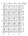
図2は、表示パネル10の回路構成の一例を表したものである。表示パネル10は、コントローラ20およびドライバ30によって各画素11がアクティブマトリクス駆動されることにより、外部から入力された映像信号Dinおよび同期信号Tinに基づく画像を表示する。表示パネル10は、行方向に延在する複数の走査線WSLと、列方向に延在する複数の信号線DTLおよび複数の電源線DSLと、行列状に配置された複数の画素11とを有している。信号線DTLが、本技術の「信号線」の一具体例に対応する。電源線DSLが、本技術の「電源線」の一具体例に対応する。
(Display panel 10)
FIG. 2 shows an example of a circuit configuration of the
走査線WSLは、各画素11の選択に用いられるものであり、各画素11を所定の単位(例えば画素行)ごとに選択する選択パルスを各画素11に供給するものである。信号線DTLは、映像信号Dinに応じた信号電圧Vsigの、各画素11への供給に用いられるものであり、信号電圧Vsigを含むデータパルスを各画素11に供給するものである。電源線DSLは、各画素11に電力を供給するものである。
The scanning line WSL is used for selecting each
各画素11は、複数のサブ画素12を有しており、具体的には、図2に示したように、4つのサブ画素12で構成されている。4つのサブ画素12は、2x2の行列で配置されている。4つのサブ画素12は、例えば、サブ画素12R,12G,12B,12Wで構成されている。サブ画素12Rは、赤色光を発する画素である。サブ画素12Gは、緑色光を発する画素である。サブ画素12Bは、青色光を発する画素である。サブ画素12Wは、白色光を発する画素である。なお、本明細書では、各画素11に含まれる4つのサブ画素12が、サブ画素12R,12G,12B,12Wで構成されているものとして、表示パネル10の説明を行う。ただし、本明細書において、各画素11に含まれる4つのサブ画素12は、上記の要素とは異なる要素によって構成されていてもよい。各画素11に含まれる4つのサブ画素12は、例えば、1つのサブ画素12R、2つのサブ画素12Gおよび1つのサブ画素12Bで構成されていてもよし、1つのサブ画素12R、1つのサブ画素12Gおよび2つのサブ画素12Bで構成されていてもよい。
Each
画素行ごとに、2本の走査線WSLが割り当てられている。具体的には、画素行に含まれるサブ画素行ごとに、1本の走査線WSLが割り当てられている。各画素行において、2本の走査線WSLは、各画素11を間に挟んで配置されている。各画素行において、画素11ごとに、2本の信号線DTLが割り当てられている。具体的には、画素行に含まれるサブ画素列ごとに、1本の信号線DTLが割り当てられている。各画素11において、2本の信号線DTLは、2つのサブ画素列の間に配置されている。
Two scanning lines WSL are assigned to each pixel row. Specifically, one scanning line WSL is assigned to each sub-pixel row included in the pixel row. In each pixel row, two scanning lines WSL are arranged with each
奇数番目の各画素行(上から1画素行目、3画素行目、・・・)には、複数の電源線DSLのうち所定の複数の電源線DSLaが割り当てられている。各電源線DSLaは、互いに電気的に接続されており、互いに同電位となっている。電源線DSLaが、本技術の「第1電源線」の一具体例に対応する。偶数番目の各画素行(上から2画素行目、4画素行目、・・・)には、複数の電源線DSLのうち所定の複数の電源線DSLbが割り当てられている。各電源線DSLbは、互いに電気的に接続されており、互いに同電位となっている。電源線DSLbが、本技術の「第2電源線」の一具体例に対応する。各電源線DSLaと、各電源線DSLbとは、互いに電気的に分離されており、互いに独立に駆動される。複数の電源線DSLaは、例えば、偶数番目の電源線DSL(上から2番目の電源線DSL、4番目の電源線DSL、・・・)である。さらに、複数の電源線DSLbは、例えば、奇数番目の電源線DSL(上から1番目の電源線DSL、3番目の電源線DSL、・・・)である。なお、複数の電源線DSLaは、奇数番目の電源線DSLであってもよい。このとき、複数の電源線DSLbは、偶数番目の電源線DSLであってもよい。 A plurality of predetermined power supply lines DSLa among the plurality of power supply lines DSL are assigned to each odd-numbered pixel row (first pixel row, third pixel row,... From the top). The power supply lines DSLa are electrically connected to each other and have the same potential. The power supply line DSLa corresponds to a specific but not limitative example of “first power supply line” of one embodiment of the present technology. A plurality of predetermined power supply lines DSLb among the plurality of power supply lines DSL are assigned to each even-numbered pixel row (the second pixel row from the top, the fourth pixel row,... ). The power supply lines DSLb are electrically connected to each other and have the same potential. The power supply line DSLb corresponds to a specific but not limitative example of “second power supply line” of one embodiment of the present technology. Each power supply line DSLa and each power supply line DSLb are electrically separated from each other and are driven independently of each other. The plurality of power supply lines DSLa are, for example, even-numbered power supply lines DSL (the second power supply line DSL from the top, the fourth power supply line DSL,... ). Further, the plurality of power supply lines DSLb are, for example, odd-numbered power supply lines DSL (first power supply line DSL, third power supply line DSL,... ). The plurality of power supply lines DSLa may be odd-numbered power supply lines DSL. At this time, the plurality of power supply lines DSLb may be even-numbered power supply lines DSL.
奇数番目の各画素行において互いに隣接する2つの画素11ごとに、1つの電源線DSLaが割り当てられている。さらに、偶数番目の各画素行において互いに隣接する2つの画素11ごとに、1つの電源線DSLbが割り当てられている。各電源線DSLaに割り当てられた2つの画素11と、各電源線DSLbに割り当てられた2つの画素11とは、1画素11分だけ互い違いにずれて配置されている。各電源線DSLaは、各電源線DSLaに割り当てられた2つの画素11の間に配置されている。各電源線DSLbは、各電源線DSLbに割り当てられた2つの画素11の間に配置されている。
One power supply line DSLa is assigned to every two
各信号線DTLは、後述の水平セレクタ31の出力端に接続されている。各走査線WSLは、後述のライトスキャナ32の出力端に接続されている。各電源線DSLaは、後述の第1電源23Aの出力端に接続されている。各電源線DSLbは、後述の第2電源23Bの出力端に接続されている。
Each signal line DTL is connected to an output terminal of a
図3は、各サブ画素12の回路構成の一例を表したものである。各サブ画素12は、例えば、画素回路13と、有機EL素子14とを有している。有機EL素子14は、例えば、アノード電極、有機層およびカソード電極が順に積層された構成を有している。有機EL素子14は、素子容量を有している。画素回路13は、有機EL素子14の発光・消光を制御する。画素回路13は、後述の書込走査によって各画素11に書き込んだ電圧を保持する機能を有している。画素回路13は、例えば、駆動トランジスタTr1、書込トランジスタTr2および保持容量Csを含んで構成されている。
FIG. 3 shows an example of the circuit configuration of each sub-pixel 12. Each sub-pixel 12 has, for example, a
書込トランジスタTr2は、駆動トランジスタTr1のゲートに対する、映像信号Dinに対応した信号電圧Vsigの印加を制御する。具体的には、書込トランジスタTr2は、信号線DTLの電圧をサンプリングするとともに、サンプリングにより得られた電圧を駆動トランジスタTr1のゲートに書き込む。駆動トランジスタTr1は、有機EL素子14に直列に接続されている。駆動トランジスタTr1は、有機EL素子14を駆動する。駆動トランジスタTr1は、書込トランジスタTr2によってサンプリングされた電圧の大きさに応じて有機EL素子14に流れる電流を制御する。保持容量Csは、駆動トランジスタTr1のゲート−ソース間に所定の電圧を保持するものである。保持容量Csは、後述の待機期間中に駆動トランジスタTr1のゲート−ソース間電圧Vgsを一定に保持する役割を有する。なお、画素回路13は、上述の2Tr1Cの回路に対して各種容量やトランジスタを付加した回路構成となっていてもよいし、上述の2Tr1Cの回路構成とは異なる回路構成となっていてもよい。
The write transistor Tr2 controls application of the signal voltage Vsig corresponding to the video signal Din to the gate of the drive transistor Tr1. Specifically, the write transistor Tr2 samples the voltage of the signal line DTL and writes the voltage obtained by the sampling in the gate of the drive transistor Tr1. The drive transistor Tr1 is connected to the
駆動トランジスタTr1および書込トランジスタTr2は、例えば、nチャネルMOS型の薄膜トランジスタ(TFT(Thin Film Transistor))により形成されている。なお、これらのトランジスタは、pチャネルMOS型のTFTにより形成されていてもよい。これらのトランジスタがエンハンスメント型であるものとして、以下の説明がなされているが、これらのトランジスタが、デプレッション型であってもよい。 The drive transistor Tr1 and the write transistor Tr2 are formed by, for example, an n-channel MOS type thin film transistor (TFT (Thin Film Transistor)). Note that these transistors may be formed by p-channel MOS type TFTs. Although the following description is given assuming that these transistors are enhancement type, these transistors may be depletion type.
各信号線DTLは、後述の水平セレクタ31の出力端と、書込トランジスタTr2のソースまたはドレインとに接続されている。各走査線WSLは、後述のライトスキャナ32の出力端と、書込トランジスタTr2のゲートとに接続されている。各電源線DSLaは、第1電源23Aの出力端と、駆動トランジスタTr1のソースまたはドレインに接続されている。各電源線DSLbは、第2電源23Bの出力端と、駆動トランジスタTr1のソースまたはドレインに接続されている。
Each signal line DTL is connected to the output terminal of the
書込トランジスタTr2のゲートは、走査線WSLに接続されている。書込トランジスタTr2のソースまたはドレインが信号線DTLに接続されている。書込トランジスタTr2のソースおよびドレインのうち信号線DTLに未接続の端子が駆動トランジスタTr1のゲートに接続されている。駆動トランジスタTr1のソースまたはドレインが電源線DSLaまたは電源線DSLbに接続されている。駆動トランジスタTr1のソースおよびドレインのうち電源線DSLaまたは電源線DSLbに未接続の端子が有機EL素子14のアノードに接続されている。保持容量Csの一端が駆動トランジスタTr1のゲートに接続されている。保持容量Csの他端が駆動トランジスタTr1のソースおよびドレインのうち有機EL素子14側の端子に接続されている。
The gate of the writing transistor Tr2 is connected to the scanning line WSL. The source or drain of the write transistor Tr2 is connected to the signal line DTL. Of the source and drain of the write transistor Tr2, the terminal not connected to the signal line DTL is connected to the gate of the drive transistor Tr1. The source or drain of the drive transistor Tr1 is connected to the power supply line DSLa or the power supply line DSLb. Of the source and drain of the drive transistor Tr1, a terminal not connected to the power supply line DSLa or the power supply line DSLb is connected to the anode of the
図4は、表示パネル10の配線レイアウトの一例を表したものである。図5は、画素回路13の配線レイアウトの一例を表したものである。各電源線DSLaおよび電源線DSLbは、各信号線DTLと同一の層内に配置されている。各電源線DSLaは、奇数番目の各画素行において割り当てられた2つの画素11に含まれる各サブ画素12に、導電性の半導体層15Aを介して電気的に接続されている。各電源線DSLbは、偶数番目の各画素行において割り当てられた2つの画素11に含まれる各サブ画素12に、導電性の半導体層15Bを介して電気的に接続されている。半導体層15A,15Bは、駆動トランジスタTr1のソース・ドレイン領域17Bと同一の層内に形成されている。半導体層15A,15Bは、例えば、駆動トランジスタTr1のソース・ドレイン領域17Bと共通の半導体層で構成されている。半導体層15Aは、コンタクトホールH4を介して電源線DSLaに接続されている。半導体層15Bは、コンタクトホールH4を介して電源線DSLbに接続されている。
FIG. 4 shows an example of the wiring layout of the
駆動トランジスタTr1のゲート17Aは、保持容量Csの一方の電極16Bを兼ねている。駆動トランジスタTr1のソース・ドレイン領域17Cが、保持容量Csの他方の電極16Aを兼ねている。駆動トランジスタTr1のソース・ドレイン領域17Cは、コンタクトホールH3を介して有機EL素子14に接続されている。保持容量Csの一方の電極16Bは、コンタクトホールH2を介して、書込トランジスタTr2のソース・ドレイン領域18Bと接続されている。書込トランジスタTr2のソース・ドレイン領域18Cが、コンタクトホールH1を介して信号線DTLに接続されている。書込トランジスタTr2のゲート18Aが走査線WSLに接続されている。
The
ドライバ30は、例えば、水平セレクタ31およびライトスキャナ32を有している。ライトスキャナ32は、本技術の「駆動回路」の一具体例に対応する。
The
水平セレクタ31は、例えば、制御信号の入力に応じて(同期して)、映像信号処理回路21から入力されたアナログの信号電圧Vsigを、各信号線DTLに印加する。水平セレクタ31は、例えば、3種類の電圧(Vofs1、Vofs2、Vsig)を出力可能となっている。具体的には、水平セレクタ31は、ライトスキャナ32により選択された画素11へ、信号線DTLを介して3種類の電圧(Vofs1、Vofs2、Vsig)を供給する。信号電圧Vsigは、映像信号Dinに対応する電圧値となっている。固定電圧Vofs1,Vofs2は、映像信号Dinとは無関係の一定電圧である。信号電圧Vsigの最小電圧は固定電圧Vofs1よりも低く、固定電圧Vofs2よりも高い電圧値となっており、信号電圧Vsigの最大電圧は固定電圧Vofs1,Vofs2よりも高い電圧値となっている。水平セレクタ31は、1水平期間ごとに、信号電圧Vsigを含むデータパルスを各信号線DTLに出力する。水平セレクタ31は、データパルスとして、信号電圧Vsigおよび固定電圧Vofs1,Vofs2の3値からなるパルスを各信号線DTLに出力する。
The
ライトスキャナ32は、複数の画素11を所定の単位ごとに走査する。具体的には、ライトスキャナ32は、1フレーム期間において、各走査線WSLに選択パルスを順次、出力する。ライトスキャナ32は、例えば、制御信号の入力に応じて(同期して)、複数の走査線WSLを所定のシーケンスで選択することにより、閾値補正準備や、閾値補正、信号電圧Vsigの書き込み、移動度補正および発光を所望の順番で実行させる。ここで、閾値補正準備とは、駆動トランジスタTr1のゲート電圧Vgを初期化する(具体的にはVofs2にする)ことを指している。閾値補正とは、駆動トランジスタTr1のゲート−ソース間電圧Vgsを駆動トランジスタTr1の閾値電圧Vthに近づける補正動作を指している。信号電圧Vsigの書き込み(信号書込)とは、駆動トランジスタTr1のゲートに対して、信号電圧Vsigを、書込トランジスタTr2を介して書き込む動作を指している。移動度補正とは、駆動トランジスタTr1のゲート−ソース間に保持される電圧(ゲート−ソース間電圧Vgs)を、駆動トランジスタTr1の移動度の大きさに応じて補正する動作を指している。信号書き込みと、移動度補正とは、互いに別個のタイミングで行われることもある。本実施の形態では、ライトスキャナ32が、1つの選択パルスを、走査線WSLへ出力することによって、信号書き込みと、移動度補正とを同時に(もしくは間髪空けずに連続して)行うようになっている。なお、以下では、「ゲート電圧Vg」との記載は、特別な説明の無い場合には、駆動トランジスタTr1のゲート電圧Vgを指す。「ゲート−ソース間電圧Vgs」との記載は、特別な説明の無い場合には、駆動トランジスタTr1のゲート−ソース間電圧Vgsを指す。「閾値電圧Vth」との記載は、特別な説明の無い場合には、駆動トランジスタTr1の閾値電圧Vthを指す。
The
ライトスキャナ32は、例えば、2種類の電圧(Von、Voff)を出力可能となっている。具体的には、ライトスキャナ32は、駆動対象の画素11へ、走査線WSLを介して2種類の電圧(Von、Voff)を供給し、書込トランジスタTr2のオンオフ制御を行う。オン電圧Vonは、書込トランジスタTr2のオン電圧以上の値となっている。オン電圧Vonは、後述の「閾値補正準備期間」や、「閾値補正期間」、「信号書込・移動度補正期間」などにライトスキャナ32から出力される選択パルスの波高値である。オフ電圧Voffは、書込トランジスタTr2のオン電圧よりも低い値となっており、かつ、オン電圧Vonよりも低い値となっている。
The
(コントローラ20)
次に、コントローラ20について説明する。コントローラ20は、例えば、映像信号処理回路21、タイミング生成回路22および電源回路23を有している。映像信号処理回路21は、例えば、外部から入力されたデジタルの映像信号Dinに対して所定の補正を行い、それにより得られた映像信号に基づいて、信号電圧Vsigを生成する。映像信号処理回路21は、例えば、生成した信号電圧Vsigを水平セレクタ31に出力する。所定の補正としては、例えば、ガンマ補正や、オーバードライブ補正などが挙げられる。タイミング生成回路22は、ドライバ30内の各回路が連動して動作するように制御するものである。タイミング生成回路22は、例えば、外部から入力された同期信号Tinに応じて(同期して)、ドライバ30内の各回路に対して制御信号を出力する。
(Controller 20)
Next, the controller 20 will be described. The controller 20 has, for example, a video
電源回路23は、水平セレクタ31、ライトスキャナ32、映像信号処理回路21およびタイミング生成回路22等の種々の回路で必要となる種々の固定電圧を生成し、供給する。電源回路23は、例えば、Vss、Vcc1、Vcc2などを生成し、上述の種々の回路に供給する。固定電圧Vss,Vcc2は、有機EL素子14の閾値電圧Velと、有機EL素子14のカソード電圧Vcathとを足し合わせた電圧(Vel+Vcath)よりも低い電圧値である。固定電圧Vcc2は、固定電圧Vssよりも高い電圧である。固定電圧Vcc1は、電圧(Vel+Vcath)よりも高い電圧値である。
The
電源回路23は、図2、図4に示したように、第1電源23Aおよび第2電源23Bを有している。第1電源23Aは、制御信号の入力に応じて(同期して)各電源線DSLaに所定の電圧を印加する。第2電源23Bは、制御信号の入力に応じて(同期して)各電源線DSLbに所定の電圧を印加する。第1電源23Aおよび第2電源23Bは、例えば、3種類の電圧(Vcc1、Vcc2、Vss)を出力可能となっている。第1電源23Aは、例えば、各電源線DSLaを介して、奇数番目の各画素行に含まれる各画素11に3種類の電圧(Vcc1、Vcc2、Vss)を供給する。第2電源23Bは、例えば、各電源線DSLbを介して、偶数番目の各画素行に含まれる各画素11に3種類の電圧(Vcc1、Vcc2、Vss)を供給する。
The
[動作]
次に、表示装置1の動作(消光から発光までの動作)について説明する。本実施の形態では、有機EL素子14のI−V特性が経時変化しても、その影響を受けることなく、有機EL素子14の発光輝度を一定に保つようにするために、有機EL素子14のI−V特性の変動に対する補償動作を組み込んでいる。さらに、本実施の形態では、駆動トランジスタTr1の閾値電圧や移動度が経時変化しても、それらの影響を受けることなく、有機EL素子14の発光輝度を一定に保つようにするために、上記閾値電圧や上記移動度の変動に対する補正動作を組み込んでいる。
[motion]
Next, the operation of the display device 1 (operation from extinction to light emission) will be described. In the present embodiment, even if the IV characteristic of the
図6は、1つの画素11に着目したときの信号線DTL、走査線WSL、および電源線DSLaもしくは電源線DSLbに印加される電圧ならびに駆動トランジスタTr1のゲート電圧Vgおよびソース電圧Vsの経時変化の一例を表したものである。なお、以下では、「ソース電圧Vs」との記載は、特別な説明の無い場合には、駆動トランジスタTr1のソース電圧Vsを指す。
FIG. 6 shows changes over time in the voltage applied to the signal line DTL, the scanning line WSL, and the power supply line DSLa or the power supply line DSLb, and the gate voltage Vg and the source voltage Vs of the drive transistor Tr1 when attention is paid to one
まず、コントローラ20およびドライバ30は、画素11を消光する。具体的には、走査線WSLの電圧がVoffとなっており、信号線DTLの電圧がVofs1となっており、電源線DSLaまたは電源線DSLbの電圧がVccとなっている時(つまり有機EL素子14が発光している時)に、電源回路23は、制御信号に応じて、電源線DSLaまたは電源線DSLbの電圧をVccからVssに下げる(時刻T1)。すると、ソース電圧VsがVss近傍まで下がり、有機EL素子14が消光する。このとき、保持容量Csを介したカップリングによりゲート電圧Vgも下がる。
First, the controller 20 and the
(補正準備期間)
次に、コントローラ20およびドライバ30は、閾値補正の準備を行う。具体的には、電源線DSLaまたは電源線DSLbの電圧がVssとなっており、かつ信号線DTLの電圧がVofs1となっている間に、ライトスキャナ32は、制御信号に応じて、走査線WSLの電圧をVoffからVonに上げる(時刻T2)。すると、ゲート電圧VgがVofs1となり、ソース電圧VsがVssとなる。このとき、ゲート−ソース間電圧Vgsは、閾値電圧Vthよりも高くなっており、駆動トランジスタTr1はオンしている。その後、水平セレクタ31は、制御信号に応じて、信号線DTLの電圧をVofs1からVosf2に切り替える。すると、ゲート電圧VgがVofs1からVosf2に下がる。このとき、ソース電圧VsはVssのまま変わらないので、ゲート−ソース間電圧Vgsが、Vofs2−Vssとなり、閾値電圧Vthよりも低くなる。その結果、駆動トランジスタTr1がオフする。その後、ライトスキャナ32は、制御信号に応じて、走査線WSLの電圧をVonからVoffに下げる(時刻T3)
(Correction preparation period)
Next, the controller 20 and the
(閾値補正期間)
次に、コントローラ20およびドライバ30は、駆動トランジスタTr1の閾値補正を行う。具体的には、信号線DTLの電圧がVofs2となっており、かつ、走査線WSLの電圧がVoffとなっている間に、電源回路23は、制御信号に応じて、電源線DSLの電圧をVssからVcc2に上げる。続いて、水平セレクタ31は、制御信号に応じて、信号線DTLの電圧をVofs2からVofs1に切り替えたのち、各画素行に対応する信号電圧Vsigを順次、信号線DTLに印加する。このとき、ライトスキャナ32は、1行目の画素行に対応する信号電圧VsigのパルスP1が入力される前に、走査線WSLの電圧をVoffからVonに上げるパルスP2を走査線WSLに印加する(時刻T4)。すると、ゲート電圧VgがVofs1まで上がり、駆動トランジスタTr1がオンするので、駆動トランジスタTr1のドレイン−ソース間に電流が流れ、ソース電圧Vsが上昇する。その結果、保持容量CsがVthに充電され、ゲート−ソース間電圧VgsがVthとなる。駆動トランジスタTr1がオンしている間に、ソース電圧VsがVofs1−Vthにまで到達しない場合(閾値補正がまだ完了していない場合)には、駆動トランジスタTr1がカットオフするまで(ゲート−ソース間電圧VgsがVthになるまで)、ライトスキャナ32は、パルスP1が入力される前に、繰り返し、パルスP2を走査線WSLに印加してもよい。
(Threshold correction period)
Next, the controller 20 and the
その後、水平セレクタ31が信号線DTLの電圧をVofsからVsigに切り替える前に、ライトスキャナ32は、制御信号に応じて、走査線WSLの電圧をVonからVoffに下げる(時刻T5)。すると、駆動トランジスタTr1のゲートがフローティングとなるので、ゲート−ソース間電圧Vgsを信号線DTLの電圧の大きさに拘わらずVthのままで維持することができる。このように、ゲート−ソース間電圧VgsをVthに設定することにより、駆動トランジスタTr1の閾値電圧Vthが画素回路13ごとにばらついた場合であっても、有機EL素子14の発光輝度がばらつくのをなくすることができる。
Then, before the
(信号書込・移動度補正期間)
閾値補正が完了した後、コントローラ20およびドライバ30は、映像信号Dinに応じた信号電圧Vsigの書き込みと、移動度補正を行う。具体的には、信号線DTLの電圧がVsigとなっており、かつ電源線DSLaまたは電源線DSLbの電圧がVcc2となっている間に、ライトスキャナ32は、制御信号に応じて、走査線WSLの電圧をVoffからVonに上げ(時刻T6)、駆動トランジスタTr1のゲートを信号線DTLに接続する。すると、ゲート電圧Vgが信号線DTLの電圧Vsigとなる。このとき、有機EL素子14のアノード電圧はこの段階ではまだ有機EL素子14の閾値電圧Velよりも小さく、有機EL素子14はカットオフしている。そのため、ゲート−ソース間の電流は有機EL素子14の素子容量Coledに流れ、素子容量Coledが充電されるので、ソース電圧VsがΔVsだけ上昇し、やがてゲート−ソース間電圧VgsがVsig+Vth−ΔVsとなる。このようにして、書き込みと同時に移動度補正が行われる。ここで、駆動トランジスタTr1の移動度が大きい程、ΔVsも大きくなるので、ゲート−ソース間電圧Vgsを発光前にΔVsだけ小さくすることにより、画素11ごとの移動度のばらつきを取り除くことができる。
(Signal writing/mobility correction period)
After the threshold correction is completed, the controller 20 and the
その後、ライトスキャナ32は、制御信号に応じて、走査線WSLの電圧をVonからVoffに下げる(時刻T7)。すると、駆動トランジスタTr1のゲートがフローティングとなり、駆動トランジスタTr1のドレイン−ソース間に電流Idsが流れ、ソース電圧Vsが上昇する。しかし、電源線DSLaまたは電源線DSLbの電圧がVcc2となっているので、有機EL素子14に閾値電圧Vel未満の電圧しか印加されない。そのため、有機EL素子14は消光を維持する。
After that, the
(発光)
各画素11において信号書込・移動度補正が完了した後、電源線33は、制御信号に応じて、電源線DSLaまたは電源線DSLbの電圧をVcc2からVcc1に上げる(時刻T8)。すると、駆動トランジスタTr1のドレイン−ソース間に電流Idsが流れ、ソース電圧Vsが上昇する。その結果、有機EL素子14に閾値電圧Vel以上の電圧が印加され、有機EL素子14が所望の輝度で発光する。
(Light emission)
After the signal writing/mobility correction in each
コントローラ20およびドライバ30は、例えば、図7に示したように、2行目の画素行から最終行の画素行に対する閾値補正および信号書込・移動度補正を、時刻T7から時刻T8の間において、画素行ごとに順次行う。
For example, as shown in FIG. 7, the controller 20 and the
次に、表示パネル10に適用される発光制御について説明する。図8は、表示パネル10に適用される発光制御の一例を表したものである。コントローラ20およびドライバ30は、1フィールド(1F)期間を前半と後半の2つの期間に分け、奇数画素行と偶数画素行とで交互に発光を行う。コントローラ20およびドライバ30は、1F期間の前半に、偶数画素行に含まれる各画素11を発光させるとともに、奇数画素行に含まれる各画素11を消光させる。コントローラ20およびドライバ30は、1F期間の後半に、偶数画素行に含まれる各画素11を消光させるとともに、奇数画素行に含まれる各画素11を発光させる。
Next, the light emission control applied to the
コントローラ20およびドライバ30は、奇数画素行に含まれる各画素11を消光させる期間(垂直のブランキング期間)に、閾値補正準備や、閾値補正、信号書込・移動度補正などを行う。さらに、コントローラ20およびドライバ30は、偶数画素行に含まれる各画素11を消光させる期間(垂直のブランキング期間)に、閾値補正準備や、閾値補正、信号書込・移動度補正などを行う。コントローラ20およびドライバ30は、1F期間の前半(垂直のブランキング期間)に、閾値補正準備を各奇数画素行に対して同時に行った後に、補正処理(例えば、閾値補正)および信号書込・移動度補正を各奇数画素行に対して順次行う。コントローラ20およびドライバ30は、さらに、1F期間の後半(垂直のブランキング期間)に、閾値補正準備を各偶数画素行に対して同時に行った後に、補正処理(例えば、閾値補正)、信号書込・移動度補正を各偶数画素行に対して順次行う。
The controller 20 and the
例えば、1F期間の前半(垂直のブランキング期間)において、第1電源23Aが各電源線DSLaの電圧をVcc2にするとともに、水平セレクタ31が信号線DTLの電圧をVofs1にしている時に、ライトスキャナ32が電圧Vonのパルス印加を奇数番目の各走査線WSLに対して順次行う。これにより、各奇数画素行に対して閾値補正が順次行われる。1F期間の後半(垂直のブランキング期間)において、第2電源23Bが各電源線DSLbの電圧をVcc2にするとともに、水平セレクタ31が信号線DTLの電圧をVofs1にしている時に、ライトスキャナ32が電圧Vonのパルス印加を偶数番目の各走査線WSLに対して順次行う。これにより、各偶数画素行に対して閾値補正が順次行われる。
For example, in the first half of the 1F period (vertical blanking period), when the
また、例えば、1F期間の前半(垂直のブランキング期間)において、第1電源23Aが各電源線DSLaの電圧をVcc2にするとともに、水平セレクタ31が信号線DTLの電圧をVsigにしている時に、ライトスキャナ32が電圧Vonのパルス印加を奇数番目の各走査線WSLに対して順次行う。これにより、各奇数画素行に対して信号書込が順次行われ、さらに、各奇数画素行に対して信号書込と同時に移動度補正が行われる。1F期間の後半(垂直のブランキング期間)において、第2電源23Bが各電源線DSLbの電圧をVcc2にするとともに、水平セレクタ31が信号線DTLの電圧をVsigにしている時に、ライトスキャナ32が電圧Vonのパルス印加を偶数番目の各走査線WSLに対して順次行う。これにより、各偶数画素行に対して信号書込が順次行われ、さらに、各偶数画素行に対して信号書込と同時に移動度補正が行われる。
Further, for example, in the first half of the 1F period (vertical blanking period), when the
なお、コントローラ20およびドライバ30は、例えば、図9に示したように、図8に示した発光制御における発光期間とブランキング期間とを入れ換えて行ってもよい。
The controller 20 and the
[効果]
次に、比較例と対比しつつ、表示装置1の効果について説明する。
[effect]
Next, the effect of the display device 1 will be described in comparison with a comparative example.
図10は、比較例に係る表示パネル110の回路構成の一例を表したものである。図11は、表示パネル110に適用される発光制御の一例を表したものである。表示パネル110では、全ての電源線DSLが1つの電源123に接続されており、全ての電源線DSLの電圧が1つの電源123によって制御される。そのため、1F期間の前半の垂直のブランキング期間に、共通の電源線DSL電位を用いて閾値補正準備が一斉に行われ、さらに、閾値補正および信号書込み・移動度補正が順次行われる。その後、共通の電源線DSL電位を一斉に発光電位まで上げることで、全面同時発光が行われ、1F期間の後半の発光期間に移行する。このように、パネル110では、複数の電源線DSLに順次、電圧を印加するスキャナ回路を用いずに、閾値補正準備、閾値補正、信号書込み、移動度補正を行うことができるので、スキャナ回路が省略された分だけ、表示パネル110を狭額縁にすることができる。しかし、この方法では、発光期間が1F期間の半分程度しかないので、フリッカーによる発光ちらつきが生じてしまう。
FIG. 10 illustrates an example of a circuit configuration of the
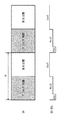
そこで、例えば、図12に示したように、表示パネル110を上半分と下半分とに分け、発光期間を1F期間で2回に分けるとともに、表示パネル110の上半分と下半分とにそれぞれ1つずつ、電源を設けることが考えられる。なお、ブランキング期間も1F期間で2回に分けられるが、1F期間内の一方のブランキング期間において、閾値補正準備、閾値補正、信号書込み、移動度補正が行われ、1F期間内の他方のブランキング期間においては、次の発光期間が始まるまで単に消光が維持される。このようにした場合には、垂直方向の走査速度を変えずに、発光周波数を2倍にすることができる。その結果、フリッカーによる発光ちらつきを低減することができる。しかし、この方法では、表示パネル110の上半分と下半分との境界に対応する箇所に筋が発生してしまう。
Therefore, for example, as shown in FIG. 12, the
一方、表示装置1では、奇数番目の各画素行に割り当てられた各電源線DSLaが互いに電気的に接続され、偶数番目の各画素行に割り当てられた各電源線DSLbが互いに電気的に接続されている。従って、各電源線DSLaに対して1つの電源23Aを用意し、各電源線DSLbに対して1つの電源23Bを用意すればよいので、電源スキャナを用意する必要がない。また、奇数番目の各画素行の発光制御と、偶数番目の各画素行の発光制御とを互いに独立に行うことができるので、例えば、1F期間を前半と後半の2つの期間に分け、奇数画素行と偶数画素行とで交互に発光を行うことが可能である。その結果、フリッカーによる発光ちらつきを抑えた狭額縁の表示パネル10を実現することができる。
On the other hand, in the display device 1, the power supply lines DSLa assigned to the odd-numbered pixel rows are electrically connected to each other, and the power supply lines DSLb assigned to the even-numbered pixel rows are electrically connected to each other. ing. Accordingly, providing a
また、表示装置1では、例えば、図4に示したように、各電源線DSLaおよび各電源線DSLbが、各信号線DTLと同一の層内に配置されているので、新たな工程を追加することなく、表示パネル10を製造することができる。従って、フリッカーによる発光ちらつきを抑えた狭額縁の表示パネル10を低コストで提供することができる。
Further, in the display device 1, for example, as shown in FIG. 4, since each power supply line DSLa and each power supply line DSLb are arranged in the same layer as each signal line DTL, a new process is added. The
また、表示装置1では、各電源線DSLを各信号線DTLと同一の層内に配置するために、表示パネル10の配線レイアウトに対して種々の工夫がなされている。まず、各電源線DSLが各信号線DTLの延在方向と同一の方向に延在している。つまり、各電源線DSLと、各信号線DTLとが互いに並走している。さらに、奇数番目の各画素行において互いに隣接する2つの画素11ごとに、1つの電源線DSLaが割り当てられている。さらに、偶数番目の各画素行において互いに隣接する2つの画素11ごとに、1つの電源線DSLbが割り当てられている。さらに、各電源線DSLaに割り当てられた2つの画素11と、各電源線DSLbに割り当てられた2つの画素11とは、1画素分だけ互い違いにずれて配置されている。これらの工夫に対して、新たな工程を追加する必要はない。従って、フリッカーによる発光ちらつきを抑えた狭額縁の表示パネル10を低コストで提供することができる。
Further, in the display device 1, in order to arrange each power supply line DSL in the same layer as each signal line DTL, various ideas have been made for the wiring layout of the
<2.変形例>
以下に、表示装置1の変形例について説明する。なお、以下では、上記実施の形態の表示装置1と共通する構成要素に対しては、同一の符号が付与される。さらに、上記実施の形態の表示装置1と共通する構成要素についての説明は、適宜、省略されるものとする。
<2. Modification>
Below, the modification of the display apparatus 1 is demonstrated. In addition, below, the same code|symbol is attached|subjected to the component which is common in the display apparatus 1 of the said embodiment. Further, the description of the components common to the display device 1 of the above-described embodiment will be appropriately omitted.
[変形例A]
上記実施の形態では、各電源線DSLaおよび各電源線DSLbが各信号線DTLの延在方向と同一の方向に延在していた。しかし、上記実施の形態において、各電源線DSLaおよび各電源線DSLbが、各信号線DTLとは異なる層内に配置されている場合には、例えば、図13に示したように、各電源線DSLaおよび各電源線DSLbは、各信号線DTLと直交する方向(つまり、各走査線WSLの延在方向と同一の方向)に延在していてもよい。ただし、その場合には、各電源線DSLaを束ねる配線DSL1,DSL2と、各電源線DSLbを束ねる配線DSL3,DSL4とが、左右の額縁領域に必要となる。なお、各電源線DSLaにおいて、配線DSL1だけでなく、配線DSL2も必要であるのは、各電源線DSLaがパネルの長手方向(左右方向)に延在している場合には、発光電流による電圧降下を抑える必要があるためである。また、各電源線DSLbにおいて、配線DSL3だけでなく、配線DSL4も必要であるのは、各電源線DSLbがパネルの長手方向(左右方向)に延在している場合には、発光電流による電圧降下を抑える必要があるためである。このように、配線DSL1,DSL2,DSL3,DSL4が左右の額縁領域に設けられている場合には、配線DSL1,DSL2,DSL3,DSL4の分だけ、左右の額縁領域が大きくなるが、スキャナ回路が設けられている場合よりも、左右の額縁領域を狭くすることができる。
[Modification A]
In the above-described embodiment, each power supply line DSLa and each power supply line DSLb extend in the same direction as the extending direction of each signal line DTL. However, in the above-described embodiment, when each power supply line DSLa and each power supply line DSLb are arranged in a layer different from each signal line DTL, for example, as shown in FIG. The DSLa and each power supply line DSLb may extend in a direction orthogonal to each signal line DTL (that is, the same direction as the extending direction of each scanning line WSL). However, in that case, wirings DSL1 and DSL2 that bundle the power supply lines DSLa and wirings DSL3 and DSL4 that bundle the power supply lines DSLb are required in the left and right frame regions. In addition, not only the wiring DSL1 but also the wiring DSL2 is required in each power supply line DSLa. When each power supply line DSLa extends in the longitudinal direction (left-right direction) of the panel, the voltage due to the light emission current is required. This is because it is necessary to suppress the descent. Further, in each power supply line DSLb, not only the wiring DSL3 but also the wiring DSL4 is necessary. When each power supply line DSLb extends in the longitudinal direction (horizontal direction) of the panel, the voltage due to the light emission current is required. This is because it is necessary to suppress the descent. In this way, when the wirings DSL1, DSL2, DSL3, DSL4 are provided in the left and right frame regions, the left and right frame regions are increased by the amount of the wirings DSL1, DSL2, DSL3, DSL4, but the scanner circuit The left and right frame regions can be made narrower than when provided.
[変形例B]
上記実施の形態では、各画素11に含まれる4つのサブ画素12は、2x2の行列に配置されていた。しかし、上記実施の形態および変形例Aにおいて、各画素11に含まれる4つのサブ画素12は、例えば、図14に示したように、1x4の行列に配置されていてもよい。
[Modification B]
In the above embodiment, the four sub-pixels 12 included in each
本変形例では、各画素11は、複数のサブ画素12で構成されている。サブ画素12が、本技術の「サブ画素」の一具体例に対応する。さらに、画素行ごとに、1本の走査線WSLが割り当てられており、各画素行において、サブ画素12ごとに、1本の信号線DTLが割り当てられている。
In this modification, each
奇数番目の各画素行(上から1画素行目、3画素行目、・・・)には、複数の電源線DSLのうち所定の複数の電源線DSLaが割り当てられている。偶数番目の各画素行(上から2画素行目、4画素行目、・・・)には、複数の電源線DSLのうち所定の複数の電源線DSLbが割り当てられている。複数の電源線DSLaは、例えば、偶数番目の電源線DSL(上から2番目の電源線DSL、4番目の電源線DSL、・・・)である。さらに、複数の電源線DSLbは、例えば、奇数番目の電源線DSL(上から1番目の電源線DSL、3番目の電源線DSL、・・・)である。なお、複数の電源線DSLaは、奇数番目の電源線DSLであってもよい。このとき、複数の電源線DSLbは、偶数番目の電源線DSLであってもよい。 A plurality of predetermined power supply lines DSLa among the plurality of power supply lines DSL are assigned to each odd-numbered pixel row (first pixel row, third pixel row,... From the top). A plurality of predetermined power supply lines DSLb among the plurality of power supply lines DSL are assigned to each even-numbered pixel row (the second pixel row from the top, the fourth pixel row,... ). The plurality of power supply lines DSLa are, for example, even-numbered power supply lines DSL (the second power supply line DSL from the top, the fourth power supply line DSL,... ). Further, the plurality of power supply lines DSLb are, for example, odd-numbered power supply lines DSL (first power supply line DSL, third power supply line DSL,... ). The plurality of power supply lines DSLa may be odd-numbered power supply lines DSL. At this time, the plurality of power supply lines DSLb may be even-numbered power supply lines DSL.
奇数番目の各画素行において互いに隣接する2つのサブ画素12ごとに、1つの電源線DSLaが割り当てられている。さらに、偶数番目の各画素行において互いに隣接する2つのサブ画素12ごとに、1つの電源線DSLbが割り当てられている。各電源線DSLaに割り当てられた2つのサブ画素12と、各電源線DSLbに割り当てられた2つのサブ画素12とは、1サブ画素12分だけ互い違いにずれて配置されている。各電源線DSLaは、各電源線DSLaに割り当てられた2つのサブ画素12の間に配置されている。各電源線DSLbは、各電源線DSLbに割り当てられた2つのサブ画素12の間に配置されている。
One power line DSLa is assigned to every two sub-pixels 12 adjacent to each other in each odd-numbered pixel row. Further, one power supply line DSLb is assigned to every two sub-pixels 12 adjacent to each other in each even-numbered pixel row. The two sub-pixels 12 assigned to each power supply line DSLa and the two sub-pixels 12 assigned to each power supply line DSLb are staggered by one
各信号線DTLは、水平セレクタ31の出力端に接続されている。各走査線WSLは、ライトスキャナ32の出力端に接続されている。各電源線DSLaは、第1電源23Aの出力端に接続されている。各電源線DSLbは、第2電源23Bの出力端に接続されている。
Each signal line DTL is connected to the output end of the
本変形例では、上記実施の形態と同様、フリッカーによる発光ちらつきを抑えた狭額縁の表示パネル10を低コストで提供することができる。
In this modified example, as in the above embodiment, it is possible to provide the
ところで、本変形例においても、各電源線DSLを各走査線WSLと同一の層内に配置するために、表示パネル10の配線レイアウトに対して種々の工夫がなされている。まず、各電源線DSLが各信号線の延在方向と同一の方向に延在している。さらに、奇数番目の各画素行において互いに隣接する2つのサブ画素12ごとに、1つの電源線DSLaが割り当てられている。さらに、偶数番目の各画素行において互いに隣接する2つのサブ画素12ごとに、1つの電源線DSLbが割り当てられている。さらに、各電源線DSLaに割り当てられた2つのサブ画素12と、各電源線DSLbに割り当てられた2つのサブ画素12とは、1画素分だけ互い違いにずれて配置されている。これらの工夫に対して、新たな工程を追加する必要はない。従って、本変形例においても、フリッカーによる発光ちらつきを抑えた狭額縁の表示パネル10を低コストで提供することができる。
By the way, also in this modification, in order to arrange each power supply line DSL in the same layer as each scanning line WSL, various measures have been taken for the wiring layout of the
[変形例C]
上記実施の形態では、各画素11は、4つのサブ画素12を有していた。しかし、上記実施の形態および変形例Aにおいて、各画素11は、例えば、図15に示したように、3つのサブ画素12を有していてもよい。3つのサブ画素12は、1x3の行列に配置されている。各画素11に含まれる3つのサブ画素12は、例えば、サブ画素11R,11G,11Bで構成されている。本変形例では、各サブ画素12と、複数の走査線WSL、複数の信号線DTLおよび複数の電源線DSLとの接続態様は、上記変形例Aと同様である。
[Modification C]
In the above embodiment, each
本変形例では、上記実施の形態と同様、フリッカーによる発光ちらつきを抑えた狭額縁の表示パネル10を低コストで提供することができる。
In this modified example, as in the above embodiment, it is possible to provide the
<3.適用例>
以下、上記実施の形態およびその変形例(以下、「上記実施の形態等」と称する。)で説明した表示装置1の適用例について説明する。上記実施の形態の表示装置1は、テレビジョン装置、デジタルカメラ、ノート型パーソナルコンピュータ、携帯電話等の携帯端末装置あるいはビデオカメラなど、外部から入力された映像信号あるいは内部で生成した映像信号を、画像あるいは映像として表示するあらゆる分野の電子機器の表示装置に適用することが可能である。
<3. Application example>
Hereinafter, application examples of the display device 1 described in the above-described embodiment and its modifications (hereinafter, referred to as “the above-described embodiment and the like”) will be described. The display device 1 according to the above-described embodiment is a television device, a digital camera, a notebook personal computer, a mobile terminal device such as a mobile phone, a video camera, or the like. The present invention can be applied to display devices of electronic devices in all fields that display images or images.
図16は、本適用例に係る電子機器2の概略構成例を表したものである。電子機器2は、例えば、折りたたみ可能な2枚の板状の筐体のうちの一方の筐体の主面に表示面2Aを備えたノート型のパーソナルコンピュータである。電子機器2は、上記実施の形態等の表示装置1を備えており、例えば、表示面2Aの位置に表示パネル10を備えている。本適用例では、表示装置1が設けられているので、表示面2Aの周囲に設けられたフレームが狭額縁となっている。
FIG. 16 illustrates a schematic configuration example of the
以上、実施の形態、変形例および適用例を挙げて本技術を説明したが、本技術は実施の形態等に限定されるものではなく、種々変形が可能である。なお、本明細書中に記載された効果は、あくまで例示である。本技術の効果は、本明細書中に記載された効果に限定されるものではない。本技術が、本明細書中に記載された効果以外の効果を持っていてもよい。 Although the present technology has been described above with reference to the embodiments, modified examples, and application examples, the present technology is not limited to the embodiments and the like, and various modifications can be made. The effects described in this specification are merely examples. The effects of the present technology are not limited to the effects described in this specification. The present technology may have effects other than the effects described in the present specification.
また、例えば、本技術は以下のような構成を取ることができる。
(1)
行列状に配置された複数の画素と、
行方向に延在する複数の走査線と、
列方向に延在する複数の信号線および複数の電源線と
を備え、
複数の電源線は、
奇数番目の各画素行に割り当てられるとともに互いに電気的に接続された複数の第1電源線と、
偶数番目の各画素行に割り当てられるとともに互いに電気的に接続された複数の第2電源線と
により構成されている
表示パネル。
(2)
奇数番目の各画素行において互いに隣接する2つの前記画素ごとに、1つの前記第1電源線が割り当てられ、
偶数番目の各画素行において互いに隣接する2つの前記画素ごとに、1つの前記第2電源線が割り当てられている
(1)に記載の表示パネル。
(3)
各前記第1電源線に割り当てられた2つの前記画素と、各前記第2電源線に割り当てられた2つの前記画素とは、1画素分だけ互い違いにずれて配置されている
(2)に記載の表示パネル。
(4)
各画素は、複数のサブ画素で構成され、
奇数番目の各画素行において互いに隣接する2つの前記サブ画素ごとに、1つの前記第1電源線が割り当てられ、
偶数番目の各画素行において互いに隣接する2つの前記サブ画素ごとに、1つの前記第2電源線が割り当てられている
(1)に記載の表示パネル。
(5)
各前記第1電源線に割り当てられた2つの前記サブ画素と、各前記第2電源線に割り当てられた2つの前記サブ画素とは、1サブ画素分だけ互い違いにずれて配置されている
(4)に記載の表示パネル。
(6)
各前記電源線は、各前記信号線と同一の層内に配置されている
(1)ないし(5)のいずれか1つに記載の表示パネル。
(7)
表示パネルと、
前記表示パネルを駆動する駆動回路と
を備え、
前記表示パネルは、
行列状に配置された複数の画素と、
行方向に延在する複数の走査線と、
列方向に延在する複数の信号線および複数の電源線と
を有し、
複数の電源線は、
奇数番目の各画素行に割り当てられた複数の第1電源線と、
偶数番目の各画素行に割り当てられた複数の第2電源線と
により構成されている
表示装置。
(8)
前記駆動回路は、1F期間を前半と後半の2つの期間に分け、奇数画素行と偶数画素行とで交互に発光を行う
(7)に記載の表示装置。
(9)
前記駆動回路は、1F期間の前半に、偶数画素行に含まれる各前記画素を発光させるとともに、奇数画素行に含まれる各前記画素を消光させ、1F期間の後半に、偶数画素行に含まれる各前記画素を消光させるとともに、奇数画素行に含まれる各前記画素を発光させる
(8)に記載の表示装置。
(10)
前記駆動回路は、偶数画素行に含まれる各前記画素を消光させる期間に、偶数画素行に含まれる各前記画素に対して、補正処理を同時に行い、さらに、奇数画素行に含まれる各前記画素を消光させる期間に、奇数画素行に含まれる各前記画素に対して、前記補正処理を同時に行う
(9)に記載の表示装置。
Further, for example, the present technology may have the following configurations.
(1)
A plurality of pixels arranged in a matrix,
A plurality of scan lines extending in the row direction,
With a plurality of signal lines and a plurality of power lines extending in the column direction,
Multiple power lines
A plurality of first power supply lines that are assigned to the odd-numbered pixel rows and are electrically connected to each other;
A display panel configured by a plurality of second power supply lines which are allocated to each of the even-numbered pixel rows and electrically connected to each other.
(2)
One of the first power supply lines is assigned to each of the two adjacent pixels in each of the odd-numbered pixel rows,
The display panel according to (1), wherein one second power supply line is assigned to each of the two adjacent pixels in each of the even-numbered pixel rows.
(3)
The two pixels assigned to each of the first power supply lines and the two pixels assigned to each of the second power supply lines are staggered by one pixel and arranged (2). Display panel.
(4)
Each pixel is composed of multiple sub-pixels,
One first power supply line is assigned to each of the two sub-pixels adjacent to each other in each odd-numbered pixel row,
The display panel according to (1), wherein one second power supply line is assigned to each of the two sub-pixels adjacent to each other in each of the even-numbered pixel rows.
(5)
The two sub-pixels assigned to each of the first power supply lines and the two sub-pixels assigned to each of the second power supply lines are arranged so as to be staggered by one sub-pixel. Display panel described in ().
(6)
The display panel according to any one of (1) to (5), wherein the power supply lines are arranged in the same layer as the signal lines.
(7)
Display panel,
A drive circuit for driving the display panel,
The display panel is
A plurality of pixels arranged in a matrix,
A plurality of scan lines extending in the row direction,
A plurality of signal lines and a plurality of power supply lines extending in the column direction,
Multiple power lines
A plurality of first power supply lines assigned to each odd-numbered pixel row,
A display device comprising a plurality of second power supply lines assigned to each even-numbered pixel row.
(8)
The display device according to (7), wherein the drive circuit divides the 1F period into two periods, the first half and the second half, and alternately emits light in odd pixel rows and even pixel rows.
(9)
The drive circuit causes each pixel included in an even pixel row to emit light in the first half of the 1F period, and extinguishes each pixel included in an odd pixel row to cause the pixel included in the even pixel row to emit in the latter half of the 1F period. The display device according to (8), in which each of the pixels is extinguished and each of the pixels included in an odd-numbered pixel row is caused to emit light.
(10)
The drive circuit simultaneously performs a correction process on each pixel included in an even pixel row during a period in which each pixel included in an even pixel row is extinguished, and further, each of the pixels included in an odd pixel row. The display device according to (9), wherein the correction process is simultaneously performed on each of the pixels included in an odd-numbered pixel row during a period of extinguishing.
1…表示装置、10,110…表示パネル、11…画素、12,12R,12G,12B,12W…サブ画素、13…画素回路、14…有機EL素子、15A,15B…半導体層、16A,16B…電源、17A,18A…ゲート、17B,17C,18B,18C…ソース・ドレイン領域、20…コントローラ、21…映像信号処理回路、22…タイミング生成回路、23…電源回路、23A…第1電源、23B…第2電源、30…ドライバ、31…水平セレクタ、32…ライトスキャナ、123…電源、Cs…容量素子、Din…映像信号、DSL,DSLa,DSLb…電源線、DTL…信号線、H1,H2,H3,H4…コンタクトホール、T1,T2,T3,T4,T5,T6,T7,T8…時刻、Tin…同期信号、Tr1…駆動トランジスタ、Tr2…書込トランジスタ、Vcc,Vcc1,Vcc2,Vofs,Vofs1,Vofs2,Vss…固定電圧、Vg…ゲート電圧、Vgs…ゲート−ソース間電圧、Von…オン電圧、Voff…オフ電圧、Vs…ソース電圧、Vsig…信号電圧、Vth…閾値電圧、WSL…走査線。 DESCRIPTION OF SYMBOLS 1... Display device, 10, 110... Display panel, 11... Pixel, 12, 12R, 12G, 12B, 12W... Sub pixel, 13... Pixel circuit, 14... Organic EL element, 15A, 15B... Semiconductor layer, 16A, 16B ... power supply, 17A, 18A... gate, 17B, 17C, 18B, 18C... source/drain region, 20... controller, 21... video signal processing circuit, 22... timing generation circuit, 23... power supply circuit, 23A... first power supply, 23B... 2nd power supply, 30... Driver, 31... Horizontal selector, 32... Write scanner, 123... Power supply, Cs... Capacitance element, Din... Video signal, DSL, DSLa, DSLb... Power supply line, DTL... Signal line, H1, H2, H3, H4... Contact hole, T1, T2, T3, T4, T5, T6, T7, T8... Time, Tin... Sync signal, Tr1... Drive transistor, Tr2... Write transistor, Vcc, Vcc1, Vcc2, Vofs , Vofs1, Vofs2, Vss... Fixed voltage, Vg... Gate voltage, Vgs... Gate-source voltage, Von... On voltage, Voff... Off voltage, Vs... Source voltage, Vsig... Signal voltage, Vth... Threshold voltage, WSL... Scan line.
Claims (8)
列方向に延在する複数の信号線および複数の電源線と
を備え、
複数の電源線は、
奇数番目の各画素行に割り当てられるとともに互いに電気的に接続された複数の第1電源線と、
偶数番目の各画素行に割り当てられるとともに互いに電気的に接続された複数の第2電源線と
により構成されており、
前記複数の第1電源線と、前記複数の第2電源線とは、行方向に1または2つの前記画素ごとに交互に配置され、
奇数番目の各画素行において互いに隣接する2つの前記画素ごとに、1つの前記第1電源線が割り当てられ、
偶数番目の各画素行において互いに隣接する2つの前記画素ごとに、1つの前記第2電源線が割り当てられて、
前記複数の第1電源線のうちの任意の前記第1電源線に割り当てられた2つの前記画素を2つの第1画素とし、前記複数の第1電源線のうち、前記2つの第1画素に割り当てられた前記第1電源線に隣接する前記第2電源線に割り当てられた2つの前記画素を2つの第2画素としたときに、前記2つの第1画素と前記2つの第2画素とは、列方向において1画素分だけ互い違いにずれて配置されている
表示パネル。 A plurality of pixels arranged in a matrix,
With a plurality of signal lines and a plurality of power lines extending in the column direction,
Multiple power lines
A plurality of first power supply lines that are assigned to the odd-numbered pixel rows and are electrically connected to each other;
And a plurality of second power supply lines which are assigned to each even-numbered pixel row and electrically connected to each other,
The plurality of first power supply lines and the plurality of second power supply lines are alternately arranged in the row direction for each one or two of the pixels ,
One of the first power supply lines is assigned to each of the two adjacent pixels in each of the odd-numbered pixel rows,
One second power supply line is allocated to each of the two adjacent pixels in each of the even-numbered pixel rows,
Two of the pixels allocated to the arbitrary first power supply line of the plurality of first power supply lines are defined as two first pixels, and the two first pixels of the plurality of first power supply lines are defined as the two first pixels. When the two pixels assigned to the second power supply line adjacent to the assigned first power supply line are two second pixels, the two first pixels and the two second pixels are , A display panel that is staggered by one pixel in the column direction .
列方向に延在する複数の信号線および複数の電源線と
を備え、
複数の電源線は、
奇数番目の各画素行に割り当てられるとともに互いに電気的に接続された複数の第1電源線と、
偶数番目の各画素行に割り当てられるとともに互いに電気的に接続された複数の第2電源線と
により構成されており、
各画素は、複数のサブ画素で構成され、
前記複数の第1電源線と、前記複数の第2電源線とは、行方向に1または2つの前記サブ画素ごとに交互に配置され、
奇数番目の各画素行において互いに隣接する2つの前記サブ画素ごとに、1つの前記第1電源線が割り当てられ、
偶数番目の各画素行において互いに隣接する2つの前記サブ画素ごとに、1つの前記第2電源線が割り当てられ、
前記複数の第1電源線のうちの任意の前記第1電源線に割り当てられた2つの前記サブ画素を2つの第1サブ画素とし、前記複数の第1電源線のうち、前記2つの第1サブ画素に割り当てられた前記第1電源線に隣接する前記第2電源線に割り当てられた2つの前記サブ画素を2つの第2サブ画素としたときに、前記2つの第1サブ画素と前記2つの第2サブ画素とは、列方向において1サブ画素分だけ互い違いにずれて配置されている
表示パネル。 A plurality of pixels arranged in a matrix,
With a plurality of signal lines and a plurality of power lines extending in the column direction,
Multiple power lines
A plurality of first power supply lines that are assigned to the odd-numbered pixel rows and are electrically connected to each other;
And a plurality of second power supply lines which are assigned to each even-numbered pixel row and electrically connected to each other ,
Each pixel is composed of multiple sub-pixels,
The plurality of first power supply lines and the plurality of second power supply lines are alternately arranged in the row direction for each one or two of the sub-pixels,
One first power supply line is assigned to each of the two sub-pixels adjacent to each other in each odd-numbered pixel row,
One second power supply line is allocated to each of the two sub-pixels adjacent to each other in each of the even-numbered pixel rows,
Of the plurality of first power supply lines, the two sub-pixels assigned to the arbitrary first power supply line are defined as two first sub-pixels, and among the plurality of first power supply lines, the two first sub-pixels. When the two sub-pixels allocated to the second power supply line adjacent to the first power supply line allocated to the sub-pixel are two second sub-pixels, the two first sub-pixels and the two The two second sub-pixels are staggered by one sub-pixel in the column direction .
請求項1または請求項2に記載の表示パネル。 The display panel according to claim 1, wherein each of the power supply lines is arranged in the same layer as each of the signal lines.
前記表示パネルを駆動する駆動回路と
を備え、
前記表示パネルは、
行列状に配置された複数の画素と、
列方向に延在する複数の信号線および複数の電源線と
を有し、
複数の電源線は、
奇数番目の各画素行に割り当てられるとともに互いに電気的に接続された複数の第1電源線と、
偶数番目の各画素行に割り当てられるとともに互いに電気的に接続された複数の第2電源線と
により構成されており、
前記複数の第1電源線と、前記複数の第2電源線とは、行方向に1または2つの前記画素ごとに交互に配置され、
奇数番目の各画素行において互いに隣接する2つの前記画素ごとに、1つの前記第1電源線が割り当てられ、
偶数番目の各画素行において互いに隣接する2つの前記画素ごとに、1つの前記第2電源線が割り当てられて、
前記複数の第1電源線のうちの任意の前記第1電源線に割り当てられた2つの前記画素を2つの第1画素とし、前記複数の第1電源線のうち、前記2つの第1画素に割り当てられた前記第1電源線に隣接する前記第2電源線に割り当てられた2つの前記画素を2つの第2画素としたときに、前記2つの第1画素と前記2つの第2画素とは、列方向において1画素分だけ互い違いにずれて配置されている
表示装置。 Display panel,
A drive circuit for driving the display panel,
The display panel is
A plurality of pixels arranged in a matrix,
A plurality of signal lines and a plurality of power supply lines extending in the column direction,
Multiple power lines
A plurality of first power supply lines that are assigned to the odd-numbered pixel rows and are electrically connected to each other;
And a plurality of second power supply lines which are assigned to each even-numbered pixel row and electrically connected to each other,
The plurality of first power supply lines and the plurality of second power supply lines are alternately arranged in the row direction for each one or two of the pixels ,
One of the first power supply lines is assigned to each of the two adjacent pixels in each of the odd-numbered pixel rows,
One second power supply line is allocated to each of the two adjacent pixels in each of the even-numbered pixel rows,
Two of the pixels allocated to the arbitrary first power supply line of the plurality of first power supply lines are defined as two first pixels, and the two first pixels of the plurality of first power supply lines are defined as the two first pixels. When the two pixels assigned to the second power supply line adjacent to the assigned first power supply line are two second pixels, the two first pixels and the two second pixels are , A display device that is staggered by one pixel in the column direction .
前記表示パネルを駆動する駆動回路と
を備え、
前記表示パネルは、
行列状に配置された複数の画素と、
列方向に延在する複数の信号線および複数の電源線と
を有し、
複数の電源線は、
奇数番目の各画素行に割り当てられるとともに互いに電気的に接続された複数の第1電源線と、
偶数番目の各画素行に割り当てられるとともに互いに電気的に接続された複数の第2電源線と
により構成されており、
各画素は、複数のサブ画素で構成され、
前記複数の第1電源線と、前記複数の第2電源線とは、行方向に1または2つの前記サブ画素ごとに交互に配置され、
奇数番目の各画素行において互いに隣接する2つの前記サブ画素ごとに、1つの前記第1電源線が割り当てられ、
偶数番目の各画素行において互いに隣接する2つの前記サブ画素ごとに、1つの前記第2電源線が割り当てられ、
前記複数の第1電源線のうちの任意の前記第1電源線に割り当てられた2つの前記サブ画素を2つの第1サブ画素とし、前記複数の第1電源線のうち、前記2つの第1サブ画素に割り当てられた前記第1電源線に隣接する前記第2電源線に割り当てられた2つの前記サブ画素を2つの第2サブ画素としたときに、前記2つの第1サブ画素と前記2つの第2サブ画素とは、列方向において1サブ画素分だけ互い違いにずれて配置されている
表示装置。 Display panel,
A drive circuit for driving the display panel,
The display panel is
A plurality of pixels arranged in a matrix,
A plurality of signal lines and a plurality of power supply lines extending in the column direction,
Multiple power lines
A plurality of first power supply lines that are assigned to the odd-numbered pixel rows and are electrically connected to each other;
And a plurality of second power supply lines which are assigned to each even-numbered pixel row and electrically connected to each other ,
Each pixel is composed of multiple sub-pixels,
The plurality of first power supply lines and the plurality of second power supply lines are alternately arranged in the row direction for each one or two of the sub-pixels,
One first power supply line is assigned to each of the two sub-pixels adjacent to each other in each odd-numbered pixel row,
One second power supply line is allocated to each of the two sub-pixels adjacent to each other in each of the even-numbered pixel rows,
Of the plurality of first power supply lines, the two sub-pixels assigned to the arbitrary first power supply line are defined as two first sub-pixels, and among the plurality of first power supply lines, the two first sub-pixels. When the two sub-pixels allocated to the second power supply line adjacent to the first power supply line allocated to the sub-pixel are two second sub-pixels, the two first sub-pixels and the two The two second sub-pixels are staggered by one sub-pixel in the column direction .
請求項4または請求項5に記載の表示装置。 The display device according to claim 4, wherein the drive circuit divides the 1F period into two periods, a first half and a second half, and alternately emits light in an odd pixel row and an even pixel row.
請求項6に記載の表示装置。 The driving circuit causes each pixel included in an even pixel row to emit light in the first half of the 1F period and extinguishes each pixel included in an odd pixel row to be included in the even pixel row in the latter half of the 1F period. The display device according to claim 6, wherein the pixels are extinguished and the pixels included in an odd-numbered pixel row are caused to emit light.
請求項7に記載の表示装置。 The drive circuit simultaneously performs a correction process on each pixel included in an even pixel row during a period in which each pixel included in an even pixel row is extinguished, and further, each pixel included in an odd pixel row. The display device according to claim 7, wherein the correction process is simultaneously performed on each of the pixels included in an odd-numbered pixel row during a period of extinguishing.
Priority Applications (2)
| Application Number | Priority Date | Filing Date | Title |
|---|---|---|---|
| JP2015188062A JP6736276B2 (en) | 2015-09-25 | 2015-09-25 | Display panel and display device |
| US15/268,839 US9984627B2 (en) | 2015-09-25 | 2016-09-19 | Display panel and display unit |
Applications Claiming Priority (1)
| Application Number | Priority Date | Filing Date | Title |
|---|---|---|---|
| JP2015188062A JP6736276B2 (en) | 2015-09-25 | 2015-09-25 | Display panel and display device |
Publications (3)
| Publication Number | Publication Date |
|---|---|
| JP2017062374A JP2017062374A (en) | 2017-03-30 |
| JP2017062374A5 JP2017062374A5 (en) | 2018-10-25 |
| JP6736276B2 true JP6736276B2 (en) | 2020-08-05 |
Family
ID=58409778
Family Applications (1)
| Application Number | Title | Priority Date | Filing Date |
|---|---|---|---|
| JP2015188062A Active JP6736276B2 (en) | 2015-09-25 | 2015-09-25 | Display panel and display device |
Country Status (2)
| Country | Link |
|---|---|
| US (1) | US9984627B2 (en) |
| JP (1) | JP6736276B2 (en) |
Families Citing this family (6)
| Publication number | Priority date | Publication date | Assignee | Title |
|---|---|---|---|---|
| KR102636733B1 (en) * | 2016-11-30 | 2024-02-14 | 삼성디스플레이 주식회사 | Light emitting display device |
| KR20200115944A (en) | 2019-03-29 | 2020-10-08 | 삼성디스플레이 주식회사 | Organic light emitting display apparatus |
| CN111369895B (en) * | 2020-04-23 | 2022-05-13 | 上海中航光电子有限公司 | Display panel and display device |
| KR20220037909A (en) * | 2020-09-18 | 2022-03-25 | 삼성전자주식회사 | Display apparatus and control method thereof |
| KR20220050591A (en) * | 2020-10-16 | 2022-04-25 | 엘지디스플레이 주식회사 | Display device, driving circuit, and driving method |
| US11689678B2 (en) * | 2021-07-06 | 2023-06-27 | Anhui Gaozhe Information Technology Co., Ltd | Double-sided synchronous scanning device and double-sided synchronous scanner |
Family Cites Families (6)
| Publication number | Priority date | Publication date | Assignee | Title |
|---|---|---|---|---|
| WO2008152847A1 (en) * | 2007-06-12 | 2008-12-18 | Sharp Kabushiki Kaisha | Liquid crystal display device, method for driving liquid crystal display device, and television receiver |
| JP2009145531A (en) | 2007-12-13 | 2009-07-02 | Sony Corp | Display, driving method for display, and electronic equipment |
| JP2010060873A (en) * | 2008-09-04 | 2010-03-18 | Sony Corp | Image display device |
| KR101812215B1 (en) * | 2010-12-06 | 2017-12-28 | 삼성디스플레이 주식회사 | Display apparatus |
| JP2012198406A (en) * | 2011-03-22 | 2012-10-18 | Seiko Epson Corp | Driving method, controller, display device and electronic apparatus |
| GB2520726A (en) * | 2013-11-29 | 2015-06-03 | St Microelectronics Res & Dev | Read-out circuitry for an image sensor |
-
2015
- 2015-09-25 JP JP2015188062A patent/JP6736276B2/en active Active
-
2016
- 2016-09-19 US US15/268,839 patent/US9984627B2/en active Active
Also Published As
| Publication number | Publication date |
|---|---|
| US9984627B2 (en) | 2018-05-29 |
| JP2017062374A (en) | 2017-03-30 |
| US20170092197A1 (en) | 2017-03-30 |
Similar Documents
| Publication | Publication Date | Title |
|---|---|---|
| JP6736276B2 (en) | Display panel and display device | |
| KR100686335B1 (en) | Pixel circuit in display device and Driving method thereof | |
| US9466250B2 (en) | Display device and electronic apparatus, and driving method of display panel | |
| CN108986735B (en) | Control device for display panel, display device, and driving method for display panel | |
| JP5939076B2 (en) | Display device, driving circuit, driving method, and electronic apparatus | |
| JP2009169071A (en) | Display device | |
| JP2011112723A (en) | Display device, method of driving the same and electronic equipment | |
| JP2010008523A (en) | Display device | |
| US10056028B2 (en) | Display unit and electronic apparatus | |
| JP2009244526A (en) | Display apparatus | |
| CN113053281A (en) | Pixel driving circuit and electroluminescent display device including the same | |
| JP2014029423A (en) | Display panel, display device and electronic apparatus | |
| US11114034B2 (en) | Display device | |
| TW201435839A (en) | Display, display drive circuit, display drive method, and electronic apparatus | |
| US20180182290A1 (en) | Display panel and display unit | |
| TWI514350B (en) | A driving circuit, a driving method, a display device and an electronic device | |
| JP5716292B2 (en) | Display device, electronic device, and driving method of display device | |
| JP2011128442A (en) | Display panel, display device and electronic equipment | |
| JP2015094773A (en) | Display device and electronic apparatus | |
| TWI480846B (en) | Pixel circuit, display panel, display unit, and electronic system | |
| KR20110113333A (en) | Organic light emitting diode display and driving method thereof | |
| JP2015060020A (en) | Display device and electronic device | |
| US9767724B2 (en) | Display panel, display unit, and electronic apparatus | |
| JP2012255873A (en) | Display device, electronic appliance, and driving method for display device | |
| JP5891493B2 (en) | Display panel, driving method thereof, display device, and electronic apparatus |
Legal Events
| Date | Code | Title | Description |
|---|---|---|---|
| A521 | Request for written amendment filed |
Free format text: JAPANESE INTERMEDIATE CODE: A523 Effective date: 20180907 |
|
| A621 | Written request for application examination |
Free format text: JAPANESE INTERMEDIATE CODE: A621 Effective date: 20180907 |
|
| A977 | Report on retrieval |
Free format text: JAPANESE INTERMEDIATE CODE: A971007 Effective date: 20190624 |
|
| A131 | Notification of reasons for refusal |
Free format text: JAPANESE INTERMEDIATE CODE: A131 Effective date: 20190709 |
|
| A521 | Request for written amendment filed |
Free format text: JAPANESE INTERMEDIATE CODE: A523 Effective date: 20190826 |
|
| A131 | Notification of reasons for refusal |
Free format text: JAPANESE INTERMEDIATE CODE: A131 Effective date: 20200107 |
|
| A521 | Request for written amendment filed |
Free format text: JAPANESE INTERMEDIATE CODE: A523 Effective date: 20200302 |
|
| TRDD | Decision of grant or rejection written | ||
| A01 | Written decision to grant a patent or to grant a registration (utility model) |
Free format text: JAPANESE INTERMEDIATE CODE: A01 Effective date: 20200616 |
|
| A61 | First payment of annual fees (during grant procedure) |
Free format text: JAPANESE INTERMEDIATE CODE: A61 Effective date: 20200715 |
|
| R151 | Written notification of patent or utility model registration |
Ref document number: 6736276 Country of ref document: JP Free format text: JAPANESE INTERMEDIATE CODE: R151 |
|
| S303 | Written request for registration of pledge or change of pledge |
Free format text: JAPANESE INTERMEDIATE CODE: R316303 |
|
| R350 | Written notification of registration of transfer |
Free format text: JAPANESE INTERMEDIATE CODE: R350 |
|
| R250 | Receipt of annual fees |
Free format text: JAPANESE INTERMEDIATE CODE: R250 |
|
| S803 | Written request for registration of cancellation of provisional registration |
Free format text: JAPANESE INTERMEDIATE CODE: R316803 |
|
| R350 | Written notification of registration of transfer |
Free format text: JAPANESE INTERMEDIATE CODE: R350 |