JP6736149B2 - Shearing member and filtration device - Google Patents
Shearing member and filtration device Download PDFInfo
- Publication number
- JP6736149B2 JP6736149B2 JP2020518745A JP2020518745A JP6736149B2 JP 6736149 B2 JP6736149 B2 JP 6736149B2 JP 2020518745 A JP2020518745 A JP 2020518745A JP 2020518745 A JP2020518745 A JP 2020518745A JP 6736149 B2 JP6736149 B2 JP 6736149B2
- Authority
- JP
- Japan
- Prior art keywords
- filtering
- rotation direction
- filtration
- cleaning member
- filtering surface
- Prior art date
- Legal status (The legal status is an assumption and is not a legal conclusion. Google has not performed a legal analysis and makes no representation as to the accuracy of the status listed.)
- Active
Links
- 238000001914 filtration Methods 0.000 title claims description 240
- 238000010008 shearing Methods 0.000 title claims description 40
- 238000004140 cleaning Methods 0.000 claims description 45
- 239000011550 stock solution Substances 0.000 claims description 32
- 238000003756 stirring Methods 0.000 claims description 22
- 239000000463 material Substances 0.000 claims description 19
- 230000002093 peripheral effect Effects 0.000 claims description 11
- 238000011144 upstream manufacturing Methods 0.000 claims description 11
- 239000002609 medium Substances 0.000 description 21
- 239000000243 solution Substances 0.000 description 20
- 239000002002 slurry Substances 0.000 description 14
- 239000000706 filtrate Substances 0.000 description 11
- 239000007788 liquid Substances 0.000 description 5
- OKTJSMMVPCPJKN-UHFFFAOYSA-N Carbon Chemical compound [C] OKTJSMMVPCPJKN-UHFFFAOYSA-N 0.000 description 4
- 229910052799 carbon Inorganic materials 0.000 description 4
- 229910001220 stainless steel Inorganic materials 0.000 description 4
- 239000010935 stainless steel Substances 0.000 description 4
- 238000010586 diagram Methods 0.000 description 3
- 238000000034 method Methods 0.000 description 3
- 238000004062 sedimentation Methods 0.000 description 3
- 239000011248 coating agent Substances 0.000 description 2
- 238000000576 coating method Methods 0.000 description 2
- 238000007599 discharging Methods 0.000 description 2
- 239000002612 dispersion medium Substances 0.000 description 2
- 239000010419 fine particle Substances 0.000 description 2
- 238000004519 manufacturing process Methods 0.000 description 2
- 239000011347 resin Substances 0.000 description 2
- 229920005989 resin Polymers 0.000 description 2
- 238000000926 separation method Methods 0.000 description 2
- 238000005299 abrasion Methods 0.000 description 1
- 230000001154 acute effect Effects 0.000 description 1
- 235000013361 beverage Nutrition 0.000 description 1
- 235000012489 doughnuts Nutrition 0.000 description 1
- 235000013305 food Nutrition 0.000 description 1
- 238000009499 grossing Methods 0.000 description 1
- 229910000856 hastalloy Inorganic materials 0.000 description 1
- 238000012986 modification Methods 0.000 description 1
- 230000004048 modification Effects 0.000 description 1
- 238000001259 photo etching Methods 0.000 description 1
- 230000000704 physical effect Effects 0.000 description 1
- 239000013049 sediment Substances 0.000 description 1
- 239000007962 solid dispersion Substances 0.000 description 1
- 238000003860 storage Methods 0.000 description 1
Images


Classifications
-
- B—PERFORMING OPERATIONS; TRANSPORTING
- B01—PHYSICAL OR CHEMICAL PROCESSES OR APPARATUS IN GENERAL
- B01D—SEPARATION
- B01D29/00—Filters with filtering elements stationary during filtration, e.g. pressure or suction filters, not covered by groups B01D24/00 - B01D27/00; Filtering elements therefor
- B01D29/62—Regenerating the filter material in the filter
- B01D29/64—Regenerating the filter material in the filter by scrapers, brushes, nozzles, or the like, acting on the cake side of the filtering element
- B01D29/6469—Regenerating the filter material in the filter by scrapers, brushes, nozzles, or the like, acting on the cake side of the filtering element scrapers
- B01D29/6476—Regenerating the filter material in the filter by scrapers, brushes, nozzles, or the like, acting on the cake side of the filtering element scrapers with a rotary movement with respect to the filtering element
-
- A—HUMAN NECESSITIES
- A23—FOODS OR FOODSTUFFS; TREATMENT THEREOF, NOT COVERED BY OTHER CLASSES
- A23L—FOODS, FOODSTUFFS, OR NON-ALCOHOLIC BEVERAGES, NOT COVERED BY SUBCLASSES A21D OR A23B-A23J; THEIR PREPARATION OR TREATMENT, e.g. COOKING, MODIFICATION OF NUTRITIVE QUALITIES, PHYSICAL TREATMENT; PRESERVATION OF FOODS OR FOODSTUFFS, IN GENERAL
- A23L5/00—Preparation or treatment of foods or foodstuffs, in general; Food or foodstuffs obtained thereby; Materials therefor
- A23L5/20—Removal of unwanted matter, e.g. deodorisation or detoxification
-
- B—PERFORMING OPERATIONS; TRANSPORTING
- B01—PHYSICAL OR CHEMICAL PROCESSES OR APPARATUS IN GENERAL
- B01D—SEPARATION
- B01D29/00—Filters with filtering elements stationary during filtration, e.g. pressure or suction filters, not covered by groups B01D24/00 - B01D27/00; Filtering elements therefor
- B01D29/11—Filters with filtering elements stationary during filtration, e.g. pressure or suction filters, not covered by groups B01D24/00 - B01D27/00; Filtering elements therefor with bag, cage, hose, tube, sleeve or like filtering elements
- B01D29/13—Supported filter elements
- B01D29/15—Supported filter elements arranged for inward flow filtration
-
- B—PERFORMING OPERATIONS; TRANSPORTING
- B01—PHYSICAL OR CHEMICAL PROCESSES OR APPARATUS IN GENERAL
- B01D—SEPARATION
- B01D29/00—Filters with filtering elements stationary during filtration, e.g. pressure or suction filters, not covered by groups B01D24/00 - B01D27/00; Filtering elements therefor
- B01D29/44—Edge filtering elements, i.e. using contiguous impervious surfaces
- B01D29/48—Edge filtering elements, i.e. using contiguous impervious surfaces of spirally or helically wound bodies
-
- B—PERFORMING OPERATIONS; TRANSPORTING
- B01—PHYSICAL OR CHEMICAL PROCESSES OR APPARATUS IN GENERAL
- B01D—SEPARATION
- B01D29/00—Filters with filtering elements stationary during filtration, e.g. pressure or suction filters, not covered by groups B01D24/00 - B01D27/00; Filtering elements therefor
- B01D29/88—Filters with filtering elements stationary during filtration, e.g. pressure or suction filters, not covered by groups B01D24/00 - B01D27/00; Filtering elements therefor having feed or discharge devices
- B01D29/90—Filters with filtering elements stationary during filtration, e.g. pressure or suction filters, not covered by groups B01D24/00 - B01D27/00; Filtering elements therefor having feed or discharge devices for feeding
Description
本発明は、せん断部材及びそのせん断部材を備える濾過装置に関する。 The present invention relates to a shearing member and a filtering device including the shearing member.
従来、濾過装置は、1次側と2次側との境にフィルター等の濾材を備えている。濾過装置は、微細な粒子である分散相を含む気体や液体の分散媒である原液を1次側から供給し、供給された原液を濾材によって濾過することにより、2次側に濾過された濾過液を得る。濾過装置によって行われる濾過の種類は、例えば分級濾過や濃縮濾過、搾汁濾過、うらごし濾過等がある。また、濾過装置は、例えば食品や飲料の製造や電池の製造等、多くの分野にわたり用いられている。 Conventionally, a filtering device is provided with a filter material such as a filter at the boundary between the primary side and the secondary side. The filtering device supplies a stock solution, which is a dispersion medium of a gas or a liquid containing a dispersed phase which is fine particles, from a primary side, and the supplied stock solution is filtered by a filter medium, thereby filtering the secondary side. Get the liquid. The types of filtration performed by the filtration device include, for example, classification filtration, concentration filtration, squeeze filtration, and back filtration. Further, the filtration device is used in many fields such as production of foods and beverages and production of batteries.
濾過装置が備える濾材は、原液を所定のスラリー濃度を有する濾過液に濾過するために、濾過面に複数の濾過孔を有している。また、濾過装置は、濾材が有する複数の濾過孔の目詰まりが発生しないように、1次側において濾材の表面に溜まった残渣を除去するスクレーパー等の清掃部材を備えている(例えば、特許文献1参照。)。 The filter medium included in the filtration device has a plurality of filtration holes on the filtration surface in order to filter the stock solution into a filtrate having a predetermined slurry concentration. Further, the filtering device is provided with a cleaning member such as a scraper that removes the residue accumulated on the surface of the filter medium on the primary side so that the plurality of filter holes of the filter medium are not clogged (for example, Patent Document 1). See 1.).
しかしながら、清掃部材によって複数の濾過孔の目詰まりの発生を防止することができているにもかかわらず、次のような現象が発生することによって、濾過装置の2次側において所定のスラリー濃度の濾過液を得ることができなくなる場合がある。すなわち、1次側に次々と供給される原液が濾過され、清掃部材によって除去された残渣が沈降分離することなく濾過面近傍に滞留し、濃度が高くなった原液が濾材の濾過面の周囲に溜まり、略ドーナツ状に所定の厚みの層(以下、濃縮層という)が形成される場合がある。濃縮層が形成されると、濃縮層自体が濾材として機能してしまい、2次側に所定のスラリー濃度の濾過液を得ることができなくなる。このような現象は、原液が高スラリー、高粘性の場合により発生しやすい。また、原液中の分散相が微粒子である場合により発生しやすい。このため、濾過装置において、濃縮層の発生を低減又は防止して、所定のスラリー濃度の濾過液を得ることが望まれている。 However, although the cleaning member can prevent the plurality of filtration holes from being clogged, the following phenomenon occurs, which causes a predetermined slurry concentration on the secondary side of the filtration device. It may not be possible to obtain a filtrate. That is, the undiluted solution supplied to the primary side one after another is filtered, the residue removed by the cleaning member stays in the vicinity of the filtering surface without sedimentation and separation, and the concentrated undiluted solution is deposited around the filtering surface of the filter medium. There is a case where a layer having a predetermined thickness (hereinafter, referred to as a concentrated layer) is formed in the form of a doughnut, which accumulates. When the concentrated layer is formed, the concentrated layer itself functions as a filter medium, and it becomes impossible to obtain a filtrate having a predetermined slurry concentration on the secondary side. Such a phenomenon is likely to occur when the stock solution has a high slurry and a high viscosity. Further, it tends to occur when the dispersed phase in the stock solution is fine particles. Therefore, it is desired to reduce or prevent the generation of a concentrated layer in a filtration device to obtain a filtrate having a predetermined slurry concentration.
本発明は、上記の事情に鑑みてなされたもので、濾過装置が備える濾材の濾過面周囲の原液の濃縮を低減又は防止するせん断部材及び濾過装置を提供することを例示的課題とする。 The present invention has been made in view of the above circumstances, and an exemplary object of the present invention is to provide a shearing member and a filtering device that reduce or prevent the concentration of the undiluted solution around the filtering surface of the filtering medium included in the filtering device.
上記の課題を解決するために、本発明は以下の構成を有する。 In order to solve the above problems, the present invention has the following configurations.
[趣旨1]
濾過面及び前記濾過面に設けられた複数の濾過孔を有し、1次側に投入された原液を濾過するための濾材と、前記濾材に当接して回転方向に回転することにより前記濾過面を清掃する清掃部材と、前記回転方向に略直交する上下方向を長手方向として前記1次側に設けられ、前記清掃部材が取り付けられる支柱と、前記濾材、前記清掃部材及び前記支柱を収納する筒体と、を備える濾過装置に用いられるせん断部材であって、
前記清掃部材に取り付けられ、前記回転方向の下流側の端部と前記回転方向の上流側の端部とを有するブレードを備え、
前記ブレードは、前記回転方向に略直交する半径方向における前記支柱の外周側の端部によって規定される円と前記濾過面との間に少なくとも前記下流側の端部が配置され、前記下流側の端部と前記濾過面との前記半径方向における距離が前記上流側の端部と前記濾過面との前記半径方向における距離よりも小さくなるように配置される、せん断部材。[Purpose 1]
A filtering surface having a filtering surface and a plurality of filtering holes provided in the filtering surface, and a filtering material for filtering a stock solution introduced on a primary side, and the filtering surface by abutting the filtering material and rotating in a rotation direction. A cleaning member for cleaning the cleaning member, a pillar provided on the primary side with the up-down direction substantially orthogonal to the rotation direction as a longitudinal direction, to which the cleaning member is attached, the filter medium, the cleaning member, and a cylinder for housing the pillar. A shearing member used in a filtering device including a body,
A blade attached to the cleaning member, having a downstream end in the rotation direction and an upstream end in the rotation direction,
The blade is arranged such that at least the downstream end is arranged between the filtration surface and a circle defined by an outer peripheral end of the strut in a radial direction substantially orthogonal to the rotation direction, and the downstream side The shearing member is arranged such that the radial distance between the end portion and the filtering surface is smaller than the radial distance between the upstream end portion and the filtering surface.
[趣旨2]
前記ブレードは、前記下流側の端部に、複数の凸部と複数の凹部とが連続した櫛刃状の形状を有してもよい。[Purpose 2]
The blade may have a comb-like shape in which a plurality of convex portions and a plurality of concave portions are continuous at the end portion on the downstream side.
[趣旨3]
前記ブレードは、前記半径方向において前記清掃部材に複数取り付けられてもよい。[Purpose 3]
A plurality of the blades may be attached to the cleaning member in the radial direction.
[趣旨4]
濾過面及び前記濾過面に設けられた複数の濾過孔を有し、1次側に投入された原液を濾過するための濾材と、前記濾材に当接して回転方向に回転することにより前記濾過面を清掃する清掃部材と、前記回転方向に略直交する上下方向を長手方向として前記1次側に設けられ、前記清掃部材が取り付けられる支柱と、前記濾材、前記清掃部材及び前記支柱を収納する筒体と、を備える濾過装置に用いられるせん断部材であって、
前記上下方向に伸びる第1の線状部材と、前記第1の線状部材よりも前記回転方向の上流側に設けられ前記上下方向に伸びる第2の線状部材と、を備え、
前記回転方向に略直交する半径方向における前記支柱の外周側の端部によって規定される円と前記濾過面との間に少なくとも前記第1の線状部材が配置され、前記第1の線状部材と前記濾過面との前記半径方向における距離が前記第2の線状部材と前記濾過面との前記半径方向における距離よりも小さくなるように配置される、せん断部材。[Purpose 4]
A filtering surface having a filtering surface and a plurality of filtering holes provided in the filtering surface, and a filtering material for filtering a stock solution introduced on a primary side, and the filtering surface by abutting the filtering material and rotating in a rotation direction. A cleaning member for cleaning the cleaning member, a pillar provided on the primary side with the up-down direction substantially orthogonal to the rotation direction as a longitudinal direction, to which the cleaning member is attached, the filter medium, the cleaning member, and a cylinder for housing the pillar. A shearing member used in a filtering device including a body,
A first linear member extending in the vertical direction, and a second linear member provided upstream of the first linear member in the rotation direction and extending in the vertical direction,
At least the first linear member is arranged between a circle defined by an end portion on the outer peripheral side of the column in a radial direction substantially orthogonal to the rotation direction and the filtration surface, and the first linear member. The shearing member is arranged such that a distance between the filter surface and the filtering surface in the radial direction is smaller than a distance between the second linear member and the filtering surface in the radial direction.
[趣旨5]
濾過面及び前記濾過面に設けられた複数の濾過孔を有し、1次側に投入された原液を濾過するための濾材と、
前記濾材に当接して回転方向に移動することにより前記濾過面を清掃する清掃部材と、
前記回転方向に略直交する上下方向を長手方向として前記1次側に設けられ、前記清掃部材が取り付けられる支柱と、
趣旨1から趣旨4のいずれか1項に記載のせん断部材と、
前記濾材、前記清掃部材、前記支柱及び前記せん断部材を収納する筒体と、
を備える、濾過装置。[Purpose 5]
A filtering surface having a filtering surface and a plurality of filtering holes provided on the filtering surface, and a filtering material for filtering the stock solution introduced on the primary side;
A cleaning member that cleans the filtering surface by moving in the rotation direction while contacting the filtering material,
A column provided on the primary side with the up-down direction substantially orthogonal to the rotation direction as a longitudinal direction, to which the cleaning member is attached,
A shearing member according to any one of the purposes 1 to 4;
A tubular body for accommodating the filter medium, the cleaning member, the column and the shearing member;
A filtering device comprising:
[趣旨6]
前記支柱に取り付けられ、前記筒体の内壁近傍の前記原液を撹拌する撹拌部材を備えてもよい。[Purpose 6]
A stirring member that is attached to the support column and that stirs the stock solution near the inner wall of the cylindrical body may be provided.
[趣旨7]
前記支柱は、前記支柱の中心軸の周りに回転可能であってもよい。[Purpose 7]
The strut may be rotatable about a central axis of the strut.
(趣旨2−1)
濾過面及び前記濾過面に設けられた複数の濾過孔を有し、1次側に投入された原液を濾過するための濾材と、前記濾材に当接して回転方向に回転することにより前記濾過面を清掃する清掃部材と、前記回転方向に略直交する上下方向を長手方向として前記1次側に設けられ、前記清掃部材が取り付けられる支柱と、前記濾材、前記清掃部材及び前記支柱を収納する筒体と、を備える濾過装置に用いられるせん断部材であって、
前記支柱の前記回転方向に略直交する半径方向における外周側の端部によって規定される円と前記濾過面との間に少なくとも前記回転方向の下流側が配置され、前記回転方向の下流側と前記濾過面との距離が前記回転方向の上流側と前記濾過面との距離よりも小さくなるように配置される、せん断部材。
(趣旨2−2)
前記せん断部材は、ブレードであり、前記清掃部材に取り付けられてもよい。
(趣旨2−3)
前記ブレードは、前記回転方向の下流側に、複数の凸部と複数の凹部とが連続した櫛刃状の形状を有してもよい。
(趣旨2−4)
前記ブレードは、前記清掃部材に複数取り付けられてもよい。
(趣旨2−5)
前記せん断部材は、少なくとも2本の線状部材であってもよい。
(趣旨2−6)
濾過面及び前記濾過面に設けられた複数の濾過孔を有し、1次側に投入された原液を濾過するための濾材と、
前記濾材に当接して回転方向に移動することにより前記濾過面を清掃する清掃部材と、
前記回転方向に略直交する上下方向を長手方向として前記1次側に設けられ、前記清掃部材が取り付けられる支柱と、
趣旨2−1から趣旨2−5のいずれか1項に記載のせん断部材と、
前記濾材、前記清掃部材、前記支柱及び前記せん断部材を収納する筒体と、
を備える、濾過装置。
(趣旨2−7)
前記支柱に取り付けられ、前記筒体の内壁近傍の前記原液を撹拌する撹拌部材を備えてもよい。
(趣旨2−8)
前記支柱は、前記支柱の中心軸の周りに回転可能であってもよい。(Purpose 2-1)
A filtering surface having a filtering surface and a plurality of filtering holes provided in the filtering surface, and a filtering material for filtering a stock solution introduced on a primary side, and the filtering surface by abutting the filtering material and rotating in a rotation direction. A cleaning member for cleaning the cleaning member, a pillar provided on the primary side with the up-down direction substantially orthogonal to the rotation direction as a longitudinal direction, to which the cleaning member is attached, the filter medium, the cleaning member, and a cylinder for housing the pillar. A shearing member used in a filtering device including a body,
At least a downstream side in the rotation direction is arranged between a circle defined by an end portion on the outer peripheral side in a radial direction substantially orthogonal to the rotation direction of the support column and the filtration surface, and a downstream side in the rotation direction and the filtration. A shearing member arranged so that the distance to the surface is smaller than the distance between the upstream side in the rotation direction and the filtering surface.
(Purpose 2-2)
The shearing member is a blade and may be attached to the cleaning member.
(Purpose 2-3)
The blade may have a comb-like shape in which a plurality of convex portions and a plurality of concave portions are continuous on the downstream side in the rotation direction.
(Purpose 2-4)
A plurality of blades may be attached to the cleaning member.
(Purpose 2-5)
The shearing member may be at least two linear members.
(Purpose 2-6)
A filtering surface having a filtering surface and a plurality of filtering holes provided on the filtering surface, and a filtering material for filtering the stock solution introduced on the primary side;
A cleaning member for cleaning the filtering surface by moving in the rotation direction while contacting the filtering material;
A column provided on the primary side with the up-down direction substantially orthogonal to the rotation direction as a longitudinal direction, to which the cleaning member is attached,
A shearing member according to any one of gist 2-1 to gist 2-5;
A tubular body for accommodating the filter medium, the cleaning member, the column and the shearing member;
A filtering device comprising:
(Purpose 2-7)
A stirring member that is attached to the support column and that stirs the stock solution near the inner wall of the cylindrical body may be provided.
(Purpose 2-8)
The strut may be rotatable about a central axis of the strut.
本発明の更なる目的又はその他の特徴は、以下添付図面を参照して説明される好ましい実施の形態によって明らかにされるであろう。 Further objects and other features of the present invention will be made clear by the preferred embodiments described below with reference to the accompanying drawings.
本発明によれば、濾過装置が備える濾材の濾過面周囲の原液の濃縮を低減又は防止するせん断部材及び濾過装置を提供することができる。 According to the present invention, it is possible to provide a shearing member and a filtering device that reduce or prevent the concentration of the undiluted solution around the filtering surface of the filtering medium included in the filtering device.
[第1の実施形態]
<濾過装置>
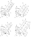
第1の実施形態に係る濾過装置10の具体的構成について図面を参照しつつ説明する。図1は、第1の実施形態の濾過装置10の構成を示す縦断面図と濾過装置の濾過エレメント130近傍の拡大縦断面図である。濾過装置10は、モータ100と、回転軸105と、原液入口110と、1次側槽部120と、支柱125と、濾材である濾過エレメント130と、清掃部材であるスクレーパー140と、せん断部材であるシアブレード150と、2次側槽部160と、濾過液出口170と、ドレン出口180と、筒体190と、を備える。[First Embodiment]
<Filtration device>
A specific configuration of the
モータ100は、回転軸105を介して支柱125に接続されている。モータ100は、回転軸105を介して支柱125並びに支柱125に取り付けられたスクレーパー140及びシアブレード150を所定の回転方向X(図2参照)及び所定の回転速度で回転させる。モータ100は、支柱125並びに支柱125に取り付けられたスクレーパー140及びシアブレード150を、例えば毎分1〜30回転させる。
The
原液入口110は、例えば固体の分散相と例えば気体又は液体の分散媒とからなる原液を1次側槽部120に投入するための開口部である。原液入口110は、回転軸105を中心とした半径方向(以下、単に半径方向という)における筒体190側(外周側)、かつ、濾過エレメント130の上側に設けられている。これにより、1次側槽部120内の原液は、半径方向の外周側から、かつ、上下方向の上側から、圧力が加えられ、濾過エレメント130に向かう流れとなる。
The
1次側槽部120は、濾過エレメント130と筒体190とによって形成される空間であり、原液入口110から投入された原液を濾過エレメント130によって濾過するための1次側の空間である。支柱125は、1次側槽部120内に上下方向にわたって設けられ、スクレーパー140及びシアブレード150を取り付けるために設けられている。図1の濾過装置10では、例えば4本の支柱125が設けられている。なお、支柱125の数は4本に限定されない。4本の支柱125は、モータ100によって回転され、1次側槽部120の原液内で回転軸105を中心として回転する。例えば、濾過エレメント130の直径が約75mmの場合、支柱125の半径方向の長さ(幅、短手方向の長さ)は、約10mm以上である。
The primary-
濾過エレメント130は、上面視略円形の円筒形状である。濾過エレメント130は、1次側槽部120の原液を濾過するための濾材であり、濾過エレメント130によって原液が濾過されることにより、2次側槽部160に所定のスラリー濃度の濾過液が得られる。濾過エレメント130は、所定のスラリー濃度の濾過液を得るための複数の孔部である濾過孔131を有する。また、濾過エレメント130の1次側槽部120に対向する面を、以下、濾過面133という。濾過エレメント130の詳細な構成は後述する。
The
スクレーパー140は、1次側槽部120内において濾過エレメント130の濾過面133に当接して設けられている。スクレーパー140は、濾過エレメント130によって原液が濾過された後に濾過面133上に残った残渣を除去することにより、濾過エレメント130の濾過孔131の目詰まりを防止する。これにより、1次側槽部120の原液が濾過孔131に円滑に供給される。スクレーパー140の詳細な構成は後述する。
The
シアブレード150は、半径方向において、1次側槽部120内におけるスクレーパー140の近傍に設けられている。シアブレード150は、濾過エレメント130の濾過面133には当接していない。スクレーパー140によって除去された残渣は、沈降分離して上下方向における下方に沈降し、ドレン出口180から不図示の容器に排出される。ここで、原液が高スラリー、高粘性の場合、スクレーパー140によって除去された残渣が沈降分離せずに濾過面133に滞留し、濾過面133近傍で原液の濃度が高くなる現象が発生し、上述した濃縮層が形成され、濃縮層自体が濾材として機能してしまい、2次側に所定のスラリー濃度の濾過液を得ることができなくなる場合がある。シアブレード150は、このような濃縮層の発生を低減又は防止するためのせん断部材である。シアブレード150の詳細な構成は後述する。
The
2次側槽部160は、濾過エレメント130内の空間であり、濾過エレメント130によって濾過された濾過液を得るための2次側の空間である。濾過液出口170は、濾過エレメント130によって濾過され、2次側槽部160に得られた濾過液を不図示の貯蔵タンクに放出するための開口部である。ドレン出口180は、濾過処理後に沈降分離された残渣を不図示の容器に排出するための開口部である。
The secondary
筒体190は、上面視略円形の円筒形状である。筒体190は、内部に支柱125、濾過エレメント130、スクレーパー140及びシアブレード150を有し、筒体190の内壁191と濾過エレメント130の濾過面133とにより1次側槽部120が形成される。図1に示すように、原液入口110は、筒体190の上部であって濾過エレメント130よりも内壁191に近い側に設けられている。半径方向において、原液は、内壁191側から濾過エレメント130に流れる。なお、内壁191近傍における原液の流れを後流という。
The
<濾過エレメント>
図1を用いて、濾過エレメント130の構成を説明する。図1の円で囲った部分は、第1の実施形態の濾過エレメント130の構成を示す拡大縦断面図である。濾過エレメント130は、例えば直径が約75mm以上、上下方向の長さが110mm以上であり、例えばステンレス鋼やハステロイ等で形成されている。濾過エレメント130は、円筒部135と、ワイヤー137と、複数の濾過孔131と、濾過面133と、を有する。<Filtration element>
The configuration of the
円筒部135は、上面視略円形の円筒形状である。ワイヤー137は、円筒部135の1次側槽部120側にコイル状に捲装される。例えば、図1の濾過装置10の濾過エレメント130では、円筒部135の外周側にワイヤー137がコイル状に捲装される。これにより、上下方向に隣り合うワイヤー137間にスリット状の濾過孔131が複数形成される。濾過孔131の大きさは、濾過液のスラリー濃度に応じて決定され、例えば3〜300μm以上である。ワイヤー137は、例えば図1に示すように、断面が三角形状となっており、濾過孔131は、上下方向に隣り合うワイヤー137のエッジとエッジとの間に形成される。これにより、濾過抵抗を小さくすることができ、高スラリー、高粘性の原液であっても、所定のスラリー濃度の濾過液を得ることができる。また、濾過面133は、ワイヤー137の断面三角形状の一辺が上下方向に連続することによって形成されている。なお、濾過エレメント130の構成はこの構成に限定されず、例えば、ウエッジスクリーンを用いてもよいし、円筒部135自体にレーザ加工やフォトエッチング加工等によって複数の濾過孔131を設ける等、他の構成であってもよい。
The
<スクレーパー>
図2を用いて、スクレーパー140の構成を説明する。図2(a)は、第1の実施形態のスクレーパー140の構成を示す図であり、筒体190の横断面図の略4分の1の部分を図示し、スクレーパー140の正面図もあわせて図示している。なお、図面の簡略化のため、図2(a)〜(c)には、シアブレード150は図示していない。スクレーパー140は、例えば、ステンレス鋼やカーボン、樹脂等で形成される。スクレーパー140は、支持部141と、刃部143と、を有する。<Scraper>
The configuration of the
支持部141は、1次側槽部120内に設けられた支柱125に例えばボルト等によって取り付けられ、刃部143を支持する。支持部141は、例えば図2(a)に示すようにヒンジである。なお、複数の部材からなるヒンジの場合、各部材の接続部に原液が入り込む場合がある。このため、支持部141の各部材の接続部に原液が入り込むことを防止する場合には、支持部141は、例えば図2(b)に示すように一体型の支持部である固定ブレード141aであってもよい。スクレーパー140の上下方向の長さは支柱125の上下方向の長さよりも短ければよい。このため、1本の支柱125に対して取り付けられるスクレーパー140の数は少なくとも1以上であればよい。
The
刃部143は、先端部145と後端部147とを有し、支持部141に例えばボルト等によって取り付けられる。刃部143は、先端部145が回転方向Xの下流側となり、後端部147が回転方向Xの上流側となるように、支持部141に取り付けられる。刃部143の上下方向の長さは支持部141の上下方向の長さと略同じであるが、これに限定されない。刃部143の先端部145は、濾過エレメント130の濾過面133に接しており、先端部145と濾過面133との接点における接線と刃部143とがなす角度αが鋭角(α<90°)となるように、支持部141及び刃部143は支柱125に取り付けられている。これにより、スクレーパー140の回転方向Xへの回転動作に応じて、濾過面133上の残渣がスクレーパー140の刃部143によって除去される。更に、このようなスクレーパー140の構成によって、濾過孔131の目詰まりが防止される。
The
また、先端部145は、図2(a)に示すように、先端部145が回転方向Xの下流側かつ濾過面133側に向かって傾斜した楔形状となっているが、楔形状でなくてもよい。スクレーパー140の先端部145は、図2(a)に示すように正面視において面形状であってもよいし、凸部と凹部とが連続する櫛刃形状であってもよい。先端部145が櫛刃形状である場合、凸部と凹部の幅や深さ、各凸部及び各凹部の形状等は、どのようなものであってもよい。
Further, as shown in FIG. 2A, the
なお、図2(c)に示すように、支持部141がヒンジである場合に、ヒンジの芯棒部にバネ149を設け、刃部143が濾過エレメント130の濾過面133と非接触状態となることを防止するようにしてもよい。
In addition, as shown in FIG. 2C, when the supporting
<撹拌ブレード>
なお、図1の濾過装置10が、撹拌部材である撹拌ブレード200を有していてもよい。図2を用いて撹拌ブレード200の構成を説明する。<Stirring blade>
The
撹拌ブレード200は、1次側槽部120内の後流を円滑にし、原液が内壁191近傍に滞留したり内壁191に付着したりすることを防止するための攪拌部材である。撹拌ブレード200は、先端部201と後端部203とを有する。撹拌ブレード200は、先端部201が内壁191側、後端部203が濾過エレメント130側となるように、後端部203が例えばボルト等により支柱125に取り付けられる。撹拌ブレード200の先端部201は、図2(a)〜(c)に示すように、内壁191との間に所定の間隙を形成するように設けられていてもよいし、図2(d)に示すように、内壁191と当接するように設けられていてもよい。なお、図2(d)にはシアブレード150を図示し、図面の見やすさのため一部の符号を省略している。
The
また、撹拌ブレード200の先端部201は、図2に示すように、凸部と凹部とが連続する櫛刃形状であってもよいし、櫛刃形状でなくてもよい。先端部201が櫛刃形状である場合、凸部と凹部の幅や深さ、各凸部及び各凹部の形状等は、どのようなものであってもよい。
Further, as shown in FIG. 2, the
<シアブレード>
図3を用いて、第1の実施形態におけるせん断部材であるシアブレード150の構成を説明する。図3は、第1の実施形態のシアブレード150の構成を示す横断面図であり、筒体190の横断面図の略4分の1の部分を図示し、シアブレード150の正面図もあわせて図示している。シアブレード150は、例えば、ステンレス鋼やカーボン、樹脂等で形成される。シアブレード150は、取り付け部151と、本体153と、を有する。取り付け部151は、本体153をスクレーパー140に取り付けるための部材である。<Shear blade>
The configuration of the
本体153は、先端部155(回転方向における下流側の端部)と後端部157(回転方向における上流側の端部)とを有し、取り付け部151を介して例えばボルト等によってスクレーパー140の刃部143に取り付けられる。本体153は、先端部155が回転方向Xの下流側となり、後端部157が回転方向Xの上流側となるように、取り付け部151に取り付けられる。本体153は、濾過エレメント130の濾過面133には接しておらず、先端部155と濾過エレメント130の濾過面133との半径方向における距離が、後端部157と濾過エレメント130の濾過面133との半径方向における距離よりも短くなるように取り付けられている。すなわち、先端部155の方が後端部157よりも濾過面133に近い。
The
シアブレード150の先端部155とスクレーパー140の先端部145との半径方向における距離(クリアランス)は、筒体190及び濾過エレメント130の直径や原液のスラリー濃度に応じて設定されるものであるが、少なくとも5mm以上確保できればよい。ここで、回転軸105の中心から支柱125の半径方向における外周側の端部までを半径R1として規定される、二点鎖線で示す円を円Cとする。濃縮層は、濾過エレメント130の濾過面133と円Cとの間で発生しやすい。このため、少なくともシアブレード150の先端部155は、濾過面133と円Cとの間に配置される。
The radial distance (clearance) between the
シアブレード150の先端部155は、図3に示すように、回転方向Xの下流側かつ濾過面133側に向かって傾斜した楔形状となっており、正面視では凸部と凹部とが連続する櫛刃形状となっている。先端部155が櫛刃形状である場合、凸部と凹部の幅や深さ、各凸部及び各凹部の形状等は、どのようなものであってもよい。シアブレード150の先端部155が、濾過エレメント130の濾過面133近傍の残渣が含まれた原液をせん断力によって分断し、分断された原液が後端部157側に流れることにより濃縮層の発生を低減又は防止し、残渣が正常に沈降分離する。なお、先端部155は楔形状でなくてもよい。
As shown in FIG. 3, the
(シアブレードの他の実施形態)
図4(a)〜(d)は、シアブレード150の他の実施形態の構成を示す断面図であり、筒体190の横断面図の略4分の1の部分を図示し、シアブレード150の正面図もあわせて図示している。図3では、シアブレード150の先端部155は櫛刃形状であったが、図4(a)のように先端部155は面形状であってもよい。また、図3ではシアブレード150の後端部157は、円C以内に位置していたが、図4(a)に示すように、円Cよりも外周側に突出する長さであってもよいし、複数の凸部と複数の凹部とが連続する櫛刃形状であってもよい。(Other embodiment of shear blade)
FIGS. 4A to 4D are cross-sectional views showing the configuration of another embodiment of the
また、図4(b)に示すように、シアブレード150が、回転軸158とストッパ159とを有する構成としてもよい。回転軸158は、シアブレード150の先端部155に矢印F1方向の力が加えられた場合に、本体153を回転軸158周り(両矢印r)に回転可能とする。ストッパ159は、本体153が必要以上に回転することを防止するために、後端部157と接触して本体153の回転を所定の位置で停止させるための部材である。
In addition, as shown in FIG. 4B, the
また、図4(c)に示すように、シアブレード150の後端部157が、複数の下向き片部157dと複数の上向き片部157uとを有する構成であってもよい。下向き片部157dは、後端側が濾過エレメント130に向かう方向に湾曲しており、上向き片部157uは、後端側が濾過エレメント130から離れる方向に湾曲している。更に、図4(d)に示すように、シアブレード150の後端部157が、複数の開口157hを有する構成であってもよい。各開口157hは、図4(d)に示すように、略矩形形状であってもよいし、例えば円形状、楕円形状等、他の形状であってもよい。また、各開口157hの大きさも同じ大きさでも異なる大きさでもよい。シアブレード150の後端部157をこれらの形状とすることで、後流を攪拌する攪拌部材としても機能し、濾過装置10の1次側槽部120に供給される原液が筒体190の内壁191近傍に滞留したり内壁191に付着したりすることを防止することができる。このため、図4(d)のシアブレード150を備える濾過装置10の場合、撹拌ブレード200を備えなくてもよい。
Further, as shown in FIG. 4C, the
以上、第1の実施形態によれば、濾過装置が備える濾材の濾過面周囲の原液の濃縮を低減又は防止するせん断部材及び濾過装置を提供することができる。 As described above, according to the first embodiment, it is possible to provide the shearing member and the filtering device that reduce or prevent the concentration of the undiluted solution around the filtering surface of the filtering medium included in the filtering device.
[第2の実施形態]
第1の実施形態では、支柱125にスクレーパー140及びシアブレード150が取り付けられる構成について説明した。第2の実施形態では、支柱が支柱の中心軸に対して回転可能であり、その支柱にスクレーパー140及びシアブレード150が取り付けられ、スクレーパー140が濾過エレメント130の濾過面133に当接する際の角度αを所定の角度に設定することが可能な濾過装置20について説明する。[Second Embodiment]
In the first embodiment, the configuration in which the
<濾過装置>
図5は、第2の実施形態の濾過装置20の構成を示す図であり、図5(a)は、筒体190の縦断面図、(b)は筒体190内の横断面図の略4分の1の部分を図示している。なお、第1の実施形態で説明した構成と同じ構成には同じ符号を付し、説明を省略する。<Filtration device>
5A and 5B are diagrams showing the configuration of the
第2の実施形態の濾過装置20は、筒体190内に、回転ピン310と、セットボルト320と、を備える。回転ピン310は、1次側槽部120内に上下方向にわたって設けられ、かつ、図5(b)中、両矢印R方向に回転可能となっている。回転ピン310には、スクレーパー140及びシアブレード150が取り付けられる。回転ピン310が両矢印R方向に回転することによって、スクレーパー140の先端部145が濾過エレメント130の濾過面133に当接する角度αを調整し、濾過面133に対するスクレーパー140の位置決めを行うことができる。図5の濾過装置20では、例えば4本の回転ピン310が設けられている。なお、回転ピン310の数は4本に限定されない。
The
セットボルト320は、回転ピン310を回転させることにより所定の角度αに調整され位置決めされたスクレーパー140が稼働時に両矢印R方向に回転しないように、回転ピン310の回転を制限するためのボルトであり、セットボルト320を締結することによって回転ピン310の回転が制限され固定される。なお、1本の回転ピン310に対して取り付けられるスクレーパー140の数は少なくとも1以上であればよい。なお、他の構成は、第1の実施形態と同様であり、説明を省略する。
The
以上、第2の実施形態によれば、濾過装置が備える濾材の濾過面周囲の原液の濃縮を低減又は防止するせん断部材及び濾過装置を提供することができる。 As described above, according to the second embodiment, it is possible to provide the shearing member and the filtering device that reduce or prevent the concentration of the undiluted solution around the filtering surface of the filtering medium included in the filtering device.
[第3の実施形態]
第1の実施形態及び第2の実施形態では、濃縮層を低減又は防止するためのせん断部材として、シアブレード150を例に説明した。第3の実施形態では、せん断部材として線状部材、例えばシアワイヤーを用いた例を説明する。[Third Embodiment]
In the first embodiment and the second embodiment, the
<濾過装置>
図6は、第3の実施形態の濾過装置30の構成を示す図であり、図6(a)は、筒体190の縦断面図を図示し、上部左側に筒体190の上面図を示し、上部右側に筒体190の横断面図を示す。また、筒体190の左側に、シアワイヤー400を示す。図6(b)は、筒体190の横断面図を図示している。なお、第1の実施形態及び第2の実施形態で説明した構成と同じ構成には同じ符号を付し、説明を省略する。濾過装置30は、例えば第2の実施形態で説明した回転ピン310を備える濾過装置20にせん断部材であるシアワイヤー400を適用した構成を示す。濾過装置30は、濃縮層を低減又は防止するためのせん断部材である線状部材であるシアワイヤー400を備える。<Filtration device>
FIG. 6 is a diagram showing the configuration of the
<シアワイヤー>
第3の実施形態におけるせん断部材であるシアワイヤーについて説明する。シアワイヤー400は、1次側槽部120内に上下方向にわたって設けられている。シアワイヤー400は、例えばステンレス鋼やカーボン等で形成されている。シアワイヤー400は、2本の第1の線状部材であるシアワイヤー400a、第2の線状部材である400bが1組となって、各回転ピン310の間にそれぞれ設けられている。例えば、回転ピン310が4本設けられている場合、シアワイヤー400は計8本設けられる。シアワイヤー400は、スクレーパー140の回転に連動して回転する。<Shear Wire>
The shear wire which is the shearing member in the third embodiment will be described. The
シアワイヤー400は、回転方向Xにおける下流側にシアワイヤー400aが配置され、回転方向Xにおける上流側にシアワイヤー400bが配置される。シアワイヤー400は、シアワイヤー400aと濾過エレメント130の濾過面133との半径方向における距離が、シアワイヤー400bと濾過エレメント130の濾過面133との半径方向における距離よりも短くなるように配置されている。言い換えれば、回転軸105からシアワイヤー400aの位置までの半径raと回転軸105からシアワイヤー400bの位置までの半径rbとが、rb>raとなるように、それぞれ配置されている。1組のシアワイヤー400をこのように配置することにより、濃縮層をせん断することができる。なお、1組のシアワイヤー400を2本のシアワイヤー400a、400bとしたが、3本以上のシアワイヤーとしてもよい。
In the
以上、第3の実施形態によれば、濾過装置が備える濾材の濾過面周囲の原液の濃縮を低減又は防止するせん断部材及び濾過装置を提供することができる。 As described above, according to the third embodiment, it is possible to provide the shearing member and the filtering device that reduce or prevent the concentration of the undiluted solution around the filtering surface of the filtering medium included in the filtering device.
[第4の実施形態]
第4の実施形態では、第1、第2の実施形態で説明したシアブレード150や第3の実施形態で説明したシアワイヤー400の硬度を向上させるための方法について説明する。[Fourth Embodiment]
In the fourth embodiment, a method for improving the hardness of the
シアブレード150は、高スラリー、高粘度の濃縮層をせん断するため、本体153の先端部155(刃部)の磨耗を抑制するために先端部155の硬度を高くすることが好ましい。このため、第4の実施形態では、本体153の少なくとも先端部155に硬度を上げる表面硬化処理を施す。硬度を上げる処理としては、例えばDLC(diamond‐like carbon:ダイヤモンドライクカーボン)コーティングによって先端部155の表面にDLC膜を生成する方法がある。先端部155の表面の硬度を上げる処理は、DLCコーティングに限定されず、他の公知の表面硬化処理方法を用いてもよい。
Since the
また、表面硬化処理を施す部位は、本体153の先端部155に限定されない。例えば、表面硬化処理を本体153全体やシアブレード150全体に施してもよい。また、シアワイヤー400に表面硬化処理を施してもよい。更に、濾過エレメント130の濾過面133や筒体190の内壁191に表面硬化処理を施してもよい。その他、濾過装置10、20、30の他の磨耗を抑制したい部位に表面硬化処理を施してもよい。
Further, the portion to be subjected to the surface hardening treatment is not limited to the
以上、第4の実施形態によれば、濾過装置が備える濾材の濾過面周囲の原液の濃縮を低減又は防止するせん断部材及び濾過装置を提供することができる。 As described above, according to the fourth embodiment, it is possible to provide the shearing member and the filtering device that reduce or prevent the concentration of the undiluted solution around the filtering surface of the filtering medium included in the filtering device.
以上、本発明の好ましい実施の形態を説明したが、本発明はこれらに限定されるものではなく、その要旨の範囲内で様々な変形や変更が可能である。 Although the preferred embodiments of the present invention have been described above, the present invention is not limited to these, and various modifications and changes can be made within the scope of the invention.
濾過装置は、図1等で示したものに限定されず、1次側と2次側との境に濾材を備える濾過装置であればよい。
図1等では、濾過エレメント130よりも外周側を1次側槽部120、内周側を2次側槽部160としたが、1次側と2次側とが逆の構成であってもよい。
せん断部材として、ブレードや線状部材を用いて説明したが、これらに限定されない。濾材の濾過面の周囲に濃縮層を発生させない機能を有するものであればよい。
支柱、スクレーパー及びシアブレードを濾過エレメントの周囲に4カ所設けたがこれに限定されず、少なくとも1カ所以上に設けられていればよい。
1つのスクレーパーに1つのシアブレードを設けたが、1つのスクレーパーに2以上のシアブレードを設けてもよい。すなわち、1つのスクレーパーに対して半径方向に二重、三重…等のシアブレードを設けてもよい。
スクレーパーやシアブレード、撹拌ブレードに櫛刃形状を設ける際に、その形状は矩形状であってもよいし、曲線状であってもよい。櫛刃状の切り欠きの深さは、例えば原液の物性や濾過装置の性能等に応じて決定される。The filtering device is not limited to that shown in FIG. 1 and the like, and may be any filtering device provided with a filter medium at the boundary between the primary side and the secondary side.
In FIG. 1 and the like, the outer peripheral side of the
Although the blade and the linear member have been described as the shearing member, the shearing member is not limited thereto. Any material may be used as long as it has a function of not generating a concentrated layer around the filtration surface of the filter material.
The support columns, scrapers, and shear blades are provided at four locations around the filtration element, but the present invention is not limited to this, and it is sufficient that they are provided at at least one location.
Although one shear blade is provided for one scraper, two or more shear blades may be provided for one scraper. That is, double, triple, etc. shear blades may be provided in the radial direction for one scraper.
When the comb blade shape is provided on the scraper, the shear blade, or the stirring blade, the shape may be rectangular or curved. The depth of the comb-shaped notch is determined according to, for example, the physical properties of the stock solution and the performance of the filtration device.
10、20、30:濾過装置 100:モータ
105:回転軸 110:原液入口
120:1次側槽部 125:支柱
130:濾過エレメント 131:濾過孔
133:濾過面 135:円筒部
137:ワイヤー 140:スクレーパー
141:支持部 141a:固定ブレード
143:刃部 145:先端部
147:後端部 149:バネ
150:シアブレード 151:取り付け部
153:本体 155:先端部
157:後端部 157d:下向き片部
157h:開口 157u:上向き片部
158:回転軸 159:ストッパ
160:2次側槽部 170:濾過液出口
180:ドレン出口 190:筒体
191:内壁 200:撹拌ブレード
201:先端部 203:後端部
310:回転ピン 320:セットボルト
400:シアワイヤー 400a、400b:シアワイヤー10, 20, 30: Filtration device 100: Motor 105: Rotating shaft 110: Stock solution inlet 120: Primary side tank part 125: Support 130: Filtration element 131: Filtration hole 133: Filtration surface 135: Cylindrical part 137: Wire 140: Scraper 141:
Claims (7)
前記清掃部材に取り付けられ、前記回転方向の下流側の端部と前記回転方向の上流側の端部とを有するブレードを備え、
前記ブレードは、前記回転方向に略直交する半径方向における前記支柱の外周側の端部によって規定される円と前記濾過面との間に少なくとも前記下流側の端部が配置され、前記下流側の端部と前記濾過面との前記半径方向における距離が前記上流側の端部と前記濾過面との前記半径方向における距離よりも小さくなるように配置される、せん断部材。A filtering surface having a filtering surface and a plurality of filtering holes provided in the filtering surface, and a filtering material for filtering a stock solution introduced on a primary side, and the filtering surface by abutting the filtering material and rotating in a rotation direction. A cleaning member for cleaning the cleaning member, a pillar provided on the primary side with the up-down direction substantially orthogonal to the rotation direction as a longitudinal direction, to which the cleaning member is attached, the filter medium, the cleaning member, and a cylinder for housing the pillar. A shearing member used in a filtering device including a body,
A blade attached to the cleaning member, having a downstream end in the rotation direction and an upstream end in the rotation direction,
The blade is arranged such that at least the downstream end is arranged between the filtration surface and a circle defined by an outer peripheral end of the strut in a radial direction substantially orthogonal to the rotation direction, and the downstream side The shearing member is arranged such that the radial distance between the end portion and the filtering surface is smaller than the radial distance between the upstream end portion and the filtering surface.
前記上下方向に伸びる第1の線状部材と、前記第1の線状部材よりも前記回転方向の上流側に設けられ前記上下方向に伸びる第2の線状部材と、を備え、
前記回転方向に略直交する半径方向における前記支柱の外周側の端部によって規定される円と前記濾過面との間に少なくとも前記第1の線状部材が配置され、前記第1の線状部材と前記濾過面との前記半径方向における距離が前記第2の線状部材と前記濾過面との前記半径方向における距離よりも小さくなるように配置される、せん断部材。A filtering surface having a filtering surface and a plurality of filtering holes provided in the filtering surface, and a filtering material for filtering a stock solution introduced on a primary side, and the filtering surface by abutting the filtering material and rotating in a rotation direction. A cleaning member for cleaning the cleaning member, a pillar provided on the primary side with the up-down direction substantially orthogonal to the rotation direction as a longitudinal direction, to which the cleaning member is attached, the filter medium, the cleaning member, and a cylinder for housing the pillar. A shearing member used in a filtering device including a body,
A first linear member extending in the vertical direction, and a second linear member provided upstream of the first linear member in the rotation direction and extending in the vertical direction,
At least the first linear member is arranged between a circle defined by an end portion on the outer peripheral side of the column in a radial direction substantially orthogonal to the rotation direction and the filtration surface, and the first linear member. The shearing member is arranged such that a distance between the filter surface and the filtering surface in the radial direction is smaller than a distance between the second linear member and the filtering surface in the radial direction.
前記濾材に当接して回転方向に移動することにより前記濾過面を清掃する清掃部材と、
前記回転方向に略直交する上下方向を長手方向として前記1次側に設けられ、前記清掃部材が取り付けられる支柱と、
請求項1から請求項4のいずれか1項に記載のせん断部材と、
前記濾材、前記清掃部材、前記支柱及び前記せん断部材を収納する筒体と、
を備える、濾過装置。A filtering surface having a filtering surface and a plurality of filtering holes provided on the filtering surface, and a filtering material for filtering the stock solution introduced on the primary side;
A cleaning member that cleans the filtering surface by moving in the rotation direction while contacting the filtering material,
A column provided on the primary side with the up-down direction substantially orthogonal to the rotation direction as a longitudinal direction, to which the cleaning member is attached,
A shearing member according to any one of claims 1 to 4,
A tubular body for accommodating the filter medium, the cleaning member, the column and the shearing member;
A filtering device comprising:
Applications Claiming Priority (3)
| Application Number | Priority Date | Filing Date | Title |
|---|---|---|---|
| JP2018093516 | 2018-05-15 | ||
| JP2018093516 | 2018-05-15 | ||
| PCT/JP2019/015933 WO2019220828A1 (en) | 2018-05-15 | 2019-04-12 | Shearing member and filtration device |
Publications (2)
| Publication Number | Publication Date |
|---|---|
| JPWO2019220828A1 JPWO2019220828A1 (en) | 2020-07-09 |
| JP6736149B2 true JP6736149B2 (en) | 2020-08-05 |
Family
ID=68539936
Family Applications (1)
| Application Number | Title | Priority Date | Filing Date |
|---|---|---|---|
| JP2020518745A Active JP6736149B2 (en) | 2018-05-15 | 2019-04-12 | Shearing member and filtration device |
Country Status (4)
| Country | Link |
|---|---|
| US (1) | US11207617B2 (en) |
| JP (1) | JP6736149B2 (en) |
| CN (1) | CN111225728B (en) |
| WO (1) | WO2019220828A1 (en) |
Families Citing this family (5)
| Publication number | Priority date | Publication date | Assignee | Title |
|---|---|---|---|---|
| DE102017205551A1 (en) * | 2017-03-31 | 2018-10-04 | Krones Ag | Bottle treating machine and method for cleaning the pump / nozzle guard of the bottle treating machine |
| JP6736149B2 (en) * | 2018-05-15 | 2020-08-05 | 株式会社荒井鉄工所 | Shearing member and filtration device |
| WO2020167623A1 (en) * | 2019-02-11 | 2020-08-20 | North Carolina State University | Self-cleaning screen |
| CN112657244A (en) * | 2020-11-11 | 2021-04-16 | 佛山市谢工机械设备有限公司 | Sewage slag removal device |
| US20220355225A1 (en) * | 2021-05-10 | 2022-11-10 | Lyco Manufacturing Inc. | Externally Fed Screen for Filtration |
Family Cites Families (114)
| Publication number | Priority date | Publication date | Assignee | Title |
|---|---|---|---|---|
| US2685968A (en) * | 1954-08-10 | Hertrich | ||
| US337423A (en) * | 1886-03-09 | Method of cleansing filters | ||
| USRE21639E (en) * | 1940-11-26 | Filter | ||
| US810020A (en) * | 1905-07-25 | 1906-01-16 | Simon A Schmitt | Filter. |
| US1033745A (en) * | 1910-04-09 | 1912-07-23 | Oliver C Smith | Strainer-cleaner. |
| US1510863A (en) * | 1920-12-23 | 1924-10-07 | William H Rose | Filter |
| US1995649A (en) * | 1932-07-09 | 1935-03-26 | American Smelting Refining | Bag filter |
| US2089702A (en) * | 1935-01-26 | 1937-08-10 | Frank B Lomax | Apparatus for filtering eggs |
| US2107040A (en) * | 1935-01-26 | 1938-02-01 | Frank B Lomax | Process of filtering eggs |
| US2089215A (en) * | 1935-02-07 | 1937-08-10 | Frank B Lomax | Apparatus for filtering eggs |
| US2050007A (en) * | 1935-05-11 | 1936-08-04 | Standard Oil Co | Continuous rotary filter |
| US2087708A (en) * | 1935-05-24 | 1937-07-20 | Dallas R Trinkle | Filter |
| US2167322A (en) * | 1936-07-17 | 1939-07-25 | Cuno Eng Corp | Filtering apparatus |
| US2243559A (en) * | 1938-06-20 | 1941-05-27 | Sf Bowser & Co Inc | Self-cleaning filter |
| US2354150A (en) * | 1941-09-13 | 1944-07-18 | Ralph L Skinner | Cleanable filter |
| US2439463A (en) * | 1943-12-18 | 1948-04-13 | Tide Water Associated Oil Comp | Oil-wax separator |
| US2363840A (en) * | 1944-01-03 | 1944-11-28 | Oliver United Filters Inc | Filter |
| US2408741A (en) * | 1944-08-11 | 1946-10-08 | Hajoca Corp | Self-cleaning straining device |
| US2713921A (en) * | 1952-08-27 | 1955-07-26 | Turner John | Filter means for collecting and recovering air-borne fibrous and other material |
| US2887787A (en) * | 1957-04-24 | 1959-05-26 | Du Pont | Scraper for doctor blade |
| US3113890A (en) * | 1961-06-26 | 1963-12-10 | Kimberly Clark Co | Apparatus for smoothing coating materials on a paper web |
| US3292201A (en) * | 1965-03-26 | 1966-12-20 | Lodding Engineering Corp | Broke and fuzz remover for doctors |
| US3333700A (en) * | 1965-05-10 | 1967-08-01 | Patterson Kelley Co | Self-cleaning screen |
| US3520410A (en) * | 1968-04-04 | 1970-07-14 | Johns Manville | Filter cake removal device for rotary drum filter |
| US3574098A (en) * | 1969-09-05 | 1971-04-06 | Environmental Sciences Inc | Process of clarifying a liquid using scorched newsprint |
| US3677413A (en) * | 1969-09-05 | 1972-07-18 | Environmental Sciences Inc | Tertiary filtering arrangement |
| US3869389A (en) * | 1970-02-13 | 1975-03-04 | Vogelsbusch Ges M B H | Process and apparatus for filtering suspensions |
| FR2099054A5 (en) * | 1970-03-10 | 1972-03-10 | Canon Kk | |
| US3762563A (en) * | 1971-02-23 | 1973-10-02 | P Petersen | Cylindrical rotary strainer |
| CA1022857A (en) * | 1972-06-22 | 1977-12-20 | Hydrocyclonics Corporation | Rotary screen filter with continuous cleaning |
| JPS4930043A (en) * | 1972-07-18 | 1974-03-18 | ||
| US3997441A (en) * | 1975-04-21 | 1976-12-14 | Pamplin Jr Lee F | Pressure filter separator |
| CH621489A5 (en) * | 1977-06-09 | 1981-02-13 | Lonza Ag | |
| US4130478A (en) * | 1977-08-25 | 1978-12-19 | Sweco, Inc. | Bowl shaped screening apparatus |
| US4146484A (en) * | 1977-09-26 | 1979-03-27 | Hycor Corporation | Doctor blade cleaning assembly |
| JPS5485037A (en) * | 1977-12-20 | 1979-07-06 | Konishiroku Photo Ind Co Ltd | Drum cleaning device of electrophotographic copier |
| US4147634A (en) * | 1978-03-15 | 1979-04-03 | Envirotech Corporation | Deflector blade for rotary drum filter |
| FI58664C (en) * | 1978-06-16 | 1981-03-10 | Valmet Oy | RENGOERINGSANORDNING FOER SKAVARBLADEN I EN PAPPERSMASKIN |
| JPS5584509A (en) * | 1978-09-18 | 1980-06-25 | Toyo Filter Kogyo Kk | Liquid filter |
| DE2944047A1 (en) * | 1979-10-31 | 1981-06-11 | Passavant-Werke Michelbacher Hütte, 6209 Aarbergen | ARCH RECTIFIER CLEANING DEVICE |
| US4273655A (en) * | 1979-12-10 | 1981-06-16 | Cpc Engineering Corporation | Doctor blade cleaning method and apparatus |
| US4337158A (en) * | 1980-03-10 | 1982-06-29 | Bodine Albert G | Cyclic wave system for unclogging water screens |
| US4316368A (en) * | 1980-10-30 | 1982-02-23 | Grasso's Koniklijke Machinefabrieken, N.V. | Multi-stage counter-current concentrating method |
| US4408724A (en) * | 1981-04-17 | 1983-10-11 | Meyer Charles R | Pulverizer device for handling liquids containing solid and semi-solid materials |
| JPS57181576A (en) * | 1981-04-30 | 1982-11-09 | Minolta Camera Co Ltd | Cleaning device |
| US4347134A (en) * | 1981-09-03 | 1982-08-31 | Svehaug Oswald C | Slurry separator having reaction nozzle driven rotory blades wiping a conical filter |
| US4552655A (en) * | 1981-10-06 | 1985-11-12 | Moshe Granot | Self-cleaning filter apparatus |
| JPS6057440B2 (en) * | 1981-11-25 | 1985-12-14 | 株式会社神戸製鋼所 | Belt press type dewatering device |
| US4673502A (en) * | 1985-05-28 | 1987-06-16 | Barnes Drill Co. | Fixed filter drum and movable scraper |
| US4673496A (en) * | 1985-09-09 | 1987-06-16 | Turner Jr Ralph W | Drum filter take-off |
| US4768645A (en) * | 1987-02-20 | 1988-09-06 | Farris Sammy D | Conveyor belt scraping apparatus |
| US4735688A (en) * | 1987-07-24 | 1988-04-05 | Schwab Albert J | Device for scraping a doctor blade |
| US4880539A (en) * | 1987-10-16 | 1989-11-14 | Cellier Corporation | Filter for filtering solids out of a liquid having a doctor blade wiping means |
| JPH01107413A (en) | 1987-10-19 | 1989-04-25 | Hitachi Cable Ltd | Fluoro-elastomer covered, insulated wire |
| JPH0352088Y2 (en) * | 1987-12-29 | 1991-11-11 | ||
| FR2632213A1 (en) * | 1988-06-01 | 1989-12-08 | Robatel Slpi | DEVICE FOR COMPLETELY ROTATING THE CAKE OBTAINED IN THE ROTOR OF A CYCLE CENTRIFUGE |
| US4994332A (en) * | 1989-07-11 | 1991-02-19 | Eltech Systems Corporation | Metal hydroxide crystallizer and filter |
| US5032229A (en) * | 1989-11-08 | 1991-07-16 | Albany International Corp. | Doctoring device for papermaking machine |
| US5026487A (en) * | 1990-01-29 | 1991-06-25 | Ingersoll-Rand Company | Method and apparatus for intermittent compression of fibrous material to aid removal from a filter surface |
| US5087365A (en) * | 1990-06-14 | 1992-02-11 | Delaware Capital Formation, Inc. | Filter with rotating wiper having indexing blades |
| US5198111A (en) * | 1991-01-10 | 1993-03-30 | Delaware Capital Formation, Inc. | Filter with reciprocating cleaner unit |
| US5262069A (en) * | 1991-02-16 | 1993-11-16 | Fsk, Inc. | Filter cake scraping method and rotary drum filter using the same |
| US5183568A (en) * | 1991-08-22 | 1993-02-02 | G A Industries, Inc. | Self-cleaning strainer |
| US5401396A (en) * | 1991-08-22 | 1995-03-28 | Ga Industries Inc. | Self-cleaning stationary basket strainer |
| US5370791A (en) * | 1991-08-22 | 1994-12-06 | G A Industries, Inc. | Backwashable self-cleaning strainer |
| US5332499A (en) * | 1992-10-28 | 1994-07-26 | Spencer Glenn E | Self-cleaning filter |
| SE501351C2 (en) * | 1993-05-05 | 1995-01-23 | Harry Nilsson | Rotating filter with filter cake removal and delivery means |
| US5407587A (en) * | 1993-08-17 | 1995-04-18 | International Paper Company | Travelling doctor blade with nozzle |
| US5443726A (en) * | 1993-10-13 | 1995-08-22 | Tm Industrial Supply, Inc. | Self-cleaning filter assembly |
| US5527462A (en) * | 1994-11-15 | 1996-06-18 | Delaware Capital Formation, Inc. | Filter with axially movable wiper |
| US5569383A (en) * | 1994-12-15 | 1996-10-29 | Delaware Capital Formation, Inc. | Filter with axially and rotatably movable wiper |
| FR2743505B1 (en) * | 1996-01-15 | 1998-02-13 | Cellier Groupe Sa | SELF-CLEANING FILTRATION DEVICE |
| DE19701689B4 (en) * | 1997-01-20 | 2005-12-08 | Mann + Hummel Gmbh | Filter for liquids, in particular slit filter |
| CA2224265A1 (en) * | 1997-12-09 | 1999-06-09 | James Ross Limited | Method and apparatus for removing contaminants from a rotating cylindrical roll |
| US6177022B1 (en) * | 1998-01-28 | 2001-01-23 | James Benenson, Jr. | Self-cleaning fuel oil strainer |
| US6517722B1 (en) * | 1998-01-28 | 2003-02-11 | James Benenson, Jr. | Self cleaning fuel oil strainer |
| US6676834B1 (en) * | 1998-01-28 | 2004-01-13 | James Benenson, Jr. | Self-cleaning water filter |
| DE19819065C1 (en) * | 1998-04-29 | 1999-10-14 | Braunschweigische Masch Bau | Semidry sugar beet fiber residue removal from centrifuge wall |
| US6187177B1 (en) * | 1999-03-12 | 2001-02-13 | Scott E. Ogburn | Industrial filter |
| JP4380872B2 (en) * | 2000-02-08 | 2009-12-09 | 株式会社ニクニ | Liquid processing equipment |
| JP3858701B2 (en) * | 2002-01-18 | 2006-12-20 | 株式会社石垣 | Clogging prevention device in screw press |
| US7083735B2 (en) * | 2003-09-03 | 2006-08-01 | Laing David A | High debris content strainer |
| JP3870231B2 (en) * | 2003-10-08 | 2007-01-17 | 恒夫 坪川 | Spiral screen for overflow water |
| US7473375B2 (en) * | 2004-05-23 | 2009-01-06 | Rosenmund Vta Ag | Method and device for removal of residual products |
| JP4606116B2 (en) | 2004-10-21 | 2011-01-05 | 前澤工業株式会社 | Filtration device |
| US7364662B2 (en) * | 2005-11-22 | 2008-04-29 | Laing David A | Scraper adjustment mechanism and method |
| US7501058B1 (en) * | 2007-05-11 | 2009-03-10 | Lawrence Sr Joseph W | Self-clearing strainer for fluid intake |
| US7445123B1 (en) * | 2007-07-10 | 2008-11-04 | Wen-Liang Chiou | Ceramic filter with a ceramic filter core cleaning device |
| JP4933606B2 (en) * | 2009-11-09 | 2012-05-16 | 大同工機株式会社 | Filter for preventing sticking of foreign substances such as algae |
| WO2011058556A2 (en) * | 2009-11-12 | 2011-05-19 | The Ballast Safe Filtration Company Ltd. | Filter proximity nozzle |
| SG174635A1 (en) * | 2010-03-08 | 2011-10-28 | Aalborg Ind Water Treat Pte Ltd | Self-cleaning filter module |
| JP5631067B2 (en) * | 2010-06-18 | 2014-11-26 | 株式会社クボタ | Screw press |
| CN201862307U (en) * | 2010-10-28 | 2011-06-15 | 上海龙宇燃油股份有限公司 | Filter for mixture of oil sludge and light oil at tank bottom of heavy oil tank |
| FI123557B (en) * | 2012-02-06 | 2013-07-15 | Andritz Oy | Method and apparatus for thinning a disc filter pre-coating layer |
| KR101358629B1 (en) * | 2012-04-03 | 2014-02-05 | 인천대학교 산학협력단 | Cyclone settling apparatus |
| US9561454B2 (en) * | 2012-10-09 | 2017-02-07 | Ovivo Inc. | Debris filter with splitter bar |
| US20140116965A1 (en) * | 2012-11-01 | 2014-05-01 | Machinerie Agricole Bois-Francs Inc. | Separator and method for separating a heterogeneous supply |
| JP2014091079A (en) * | 2012-11-02 | 2014-05-19 | Arai Tekkosho:Kk | Filtration system with multistage scraper mechanism |
| KR101517985B1 (en) * | 2012-11-06 | 2015-05-06 | 주식회사 시그너스파워 | a strainer |
| US8679335B1 (en) * | 2012-12-21 | 2014-03-25 | Saniprotex Inc. | Vehicle-mounted vacuum system and method of separating liquid and solids fractions of a sludge-like mixture inside a container |
| DK3044165T3 (en) * | 2013-09-12 | 2018-03-12 | Antel Aritma Tesisleri Insaat Sanay Ve Ticaret Anonimim Sirketi | Automatic cleaning filter with nozzle brush and gear motor |
| US9327219B2 (en) * | 2013-12-12 | 2016-05-03 | James J. Brunswick | Spiral irrigation filter cleaning apparatus |
| WO2015130253A1 (en) * | 2014-02-28 | 2015-09-03 | Antel Aritma Tesisleri Insaat Sanayi Ve Ticaret A.S. | Filtration assembly for gradually screening of fine and coarse particles in a single operational unit |
| ES2885599T3 (en) * | 2015-04-30 | 2021-12-14 | Fimic S R L | Filter for plastic material |
| US10245531B2 (en) * | 2015-06-17 | 2019-04-02 | Tm Industrial Supply, Inc. | High-efficiency automatic self-cleaning strainer |
| US10286339B2 (en) * | 2015-11-16 | 2019-05-14 | Halliburton Energy Services, Inc. | Filter screen brush assembly |
| CN205164985U (en) * | 2015-11-19 | 2016-04-20 | 湘潭离心机有限公司 | Vertical scraper discharging centrifugal machine scraper discharge device |
| JP2017131868A (en) * | 2016-01-29 | 2017-08-03 | 日本製紙株式会社 | Cake dropout device of solid-liquid separator |
| CN205379721U (en) * | 2016-01-30 | 2016-07-13 | 高美(安远)电子有限公司 | Aramid fiber slurry filter equipment |
| CN206262197U (en) * | 2016-10-10 | 2017-06-20 | 肇庆市和邦机械制造有限公司 | A kind of self-cleaning type drains machine |
| CN206152445U (en) * | 2016-11-10 | 2017-05-10 | 攀枝花市国钛科技有限公司 | Filter of area scraping device |
| US10596497B2 (en) * | 2018-04-27 | 2020-03-24 | Sune V. BACKMAN | Filter scraper |
| JP6736149B2 (en) * | 2018-05-15 | 2020-08-05 | 株式会社荒井鉄工所 | Shearing member and filtration device |
| WO2020167623A1 (en) * | 2019-02-11 | 2020-08-20 | North Carolina State University | Self-cleaning screen |
-
2019
- 2019-04-12 JP JP2020518745A patent/JP6736149B2/en active Active
- 2019-04-12 CN CN201980005141.3A patent/CN111225728B/en active Active
- 2019-04-12 WO PCT/JP2019/015933 patent/WO2019220828A1/en active Application Filing
-
2020
- 2020-11-13 US US17/097,377 patent/US11207617B2/en active Active
Also Published As
| Publication number | Publication date |
|---|---|
| US11207617B2 (en) | 2021-12-28 |
| CN111225728B (en) | 2022-04-05 |
| US20210060460A1 (en) | 2021-03-04 |
| CN111225728A (en) | 2020-06-02 |
| JPWO2019220828A1 (en) | 2020-07-09 |
| WO2019220828A1 (en) | 2019-11-21 |
Similar Documents
| Publication | Publication Date | Title |
|---|---|---|
| JP6736149B2 (en) | Shearing member and filtration device | |
| EP3171970B1 (en) | Stirring member apparatus | |
| US7395935B2 (en) | Filtering device | |
| US6588599B2 (en) | Screen for pulp processing | |
| JP4308759B2 (en) | Continuous filtration device for material mixture | |
| EP0205623B1 (en) | Pressure slit screen | |
| EP3618968A1 (en) | Decanter centrifuge | |
| US20200131703A1 (en) | Supported toothed plates in a disperser | |
| US5624558A (en) | Method and apparatus for screening a fiber suspension | |
| US7597201B2 (en) | Device for cleaning fibrous suspensions for paper production | |
| JP3396456B2 (en) | Stock selection equipment | |
| JPS6229556B2 (en) | ||
| CN102105200B (en) | Rotating knife, washing column, and method for disintegrating a crystal bed in a washing column | |
| DE202005009095U1 (en) | grinding tool | |
| NL1009609C2 (en) | Device for separating solid particles from a mainly liquid substance. | |
| JP2006348460A (en) | Slit screen and screening device equipped with the slit screen | |
| JP4617397B1 (en) | Slit screen and screen device provided with slit screen | |
| KR20120124696A (en) | A filtering apparatus for water treatment without back-washing | |
| JP2022550352A (en) | SELF-CLEANING APPARATUS AND METHOD FOR CONTINUOUS FILTRATION OF HIGH VISCOSITY FLUIDS | |
| NL1013413C2 (en) | Water treatment installation, especially for manure, has a filter device provided between separation and electroflocking devices | |
| US6273266B1 (en) | Process for the wet screening of stock suspensions in pressure graders and pressure graders screen | |
| RU2815236C1 (en) | Device and method of self-cleaning for continuous filtration of high-viscosity fluids | |
| JP2003138493A (en) | Slit screen and method of producing the same | |
| CA1287327C (en) | Pressure type slit screen | |
| JP3853826B1 (en) | Slit screen and screen device provided with the slit screen |
Legal Events
| Date | Code | Title | Description |
|---|---|---|---|
| A621 | Written request for application examination |
Free format text: JAPANESE INTERMEDIATE CODE: A621 Effective date: 20200330 |
|
| A871 | Explanation of circumstances concerning accelerated examination |
Free format text: JAPANESE INTERMEDIATE CODE: A871 Effective date: 20200330 |
|
| A975 | Report on accelerated examination |
Free format text: JAPANESE INTERMEDIATE CODE: A971005 Effective date: 20200605 |
|
| TRDD | Decision of grant or rejection written | ||
| A01 | Written decision to grant a patent or to grant a registration (utility model) |
Free format text: JAPANESE INTERMEDIATE CODE: A01 Effective date: 20200630 |
|
| A61 | First payment of annual fees (during grant procedure) |
Free format text: JAPANESE INTERMEDIATE CODE: A61 Effective date: 20200709 |
|
| R150 | Certificate of patent or registration of utility model |
Ref document number: 6736149 Country of ref document: JP Free format text: JAPANESE INTERMEDIATE CODE: R150 |
|
| R250 | Receipt of annual fees |
Free format text: JAPANESE INTERMEDIATE CODE: R250 |