JP6735744B2 - Refrigeration cycle equipment - Google Patents
Refrigeration cycle equipment Download PDFInfo
- Publication number
- JP6735744B2 JP6735744B2 JP2017524243A JP2017524243A JP6735744B2 JP 6735744 B2 JP6735744 B2 JP 6735744B2 JP 2017524243 A JP2017524243 A JP 2017524243A JP 2017524243 A JP2017524243 A JP 2017524243A JP 6735744 B2 JP6735744 B2 JP 6735744B2
- Authority
- JP
- Japan
- Prior art keywords
- heat source
- source side
- heat
- refrigerant
- pressure reducing
- Prior art date
- Legal status (The legal status is an assumption and is not a legal conclusion. Google has not performed a legal analysis and makes no representation as to the accuracy of the status listed.)
- Active
Links
Images


Classifications
-
- F—MECHANICAL ENGINEERING; LIGHTING; HEATING; WEAPONS; BLASTING
- F24—HEATING; RANGES; VENTILATING
- F24F—AIR-CONDITIONING; AIR-HUMIDIFICATION; VENTILATION; USE OF AIR CURRENTS FOR SCREENING
- F24F11/00—Control or safety arrangements
- F24F11/89—Arrangement or mounting of control or safety devices
-
- F—MECHANICAL ENGINEERING; LIGHTING; HEATING; WEAPONS; BLASTING
- F25—REFRIGERATION OR COOLING; COMBINED HEATING AND REFRIGERATION SYSTEMS; HEAT PUMP SYSTEMS; MANUFACTURE OR STORAGE OF ICE; LIQUEFACTION SOLIDIFICATION OF GASES
- F25B—REFRIGERATION MACHINES, PLANTS OR SYSTEMS; COMBINED HEATING AND REFRIGERATION SYSTEMS; HEAT PUMP SYSTEMS
- F25B1/00—Compression machines, plants or systems with non-reversible cycle
- F25B1/10—Compression machines, plants or systems with non-reversible cycle with multi-stage compression
-
- F—MECHANICAL ENGINEERING; LIGHTING; HEATING; WEAPONS; BLASTING
- F25—REFRIGERATION OR COOLING; COMBINED HEATING AND REFRIGERATION SYSTEMS; HEAT PUMP SYSTEMS; MANUFACTURE OR STORAGE OF ICE; LIQUEFACTION SOLIDIFICATION OF GASES
- F25B—REFRIGERATION MACHINES, PLANTS OR SYSTEMS; COMBINED HEATING AND REFRIGERATION SYSTEMS; HEAT PUMP SYSTEMS
- F25B40/00—Subcoolers, desuperheaters or superheaters
-
- F—MECHANICAL ENGINEERING; LIGHTING; HEATING; WEAPONS; BLASTING
- F25—REFRIGERATION OR COOLING; COMBINED HEATING AND REFRIGERATION SYSTEMS; HEAT PUMP SYSTEMS; MANUFACTURE OR STORAGE OF ICE; LIQUEFACTION SOLIDIFICATION OF GASES
- F25B—REFRIGERATION MACHINES, PLANTS OR SYSTEMS; COMBINED HEATING AND REFRIGERATION SYSTEMS; HEAT PUMP SYSTEMS
- F25B41/00—Fluid-circulation arrangements
- F25B41/30—Expansion means; Dispositions thereof
- F25B41/39—Dispositions with two or more expansion means arranged in series, i.e. multi-stage expansion, on a refrigerant line leading to the same evaporator
-
- F—MECHANICAL ENGINEERING; LIGHTING; HEATING; WEAPONS; BLASTING
- F25—REFRIGERATION OR COOLING; COMBINED HEATING AND REFRIGERATION SYSTEMS; HEAT PUMP SYSTEMS; MANUFACTURE OR STORAGE OF ICE; LIQUEFACTION SOLIDIFICATION OF GASES
- F25B—REFRIGERATION MACHINES, PLANTS OR SYSTEMS; COMBINED HEATING AND REFRIGERATION SYSTEMS; HEAT PUMP SYSTEMS
- F25B7/00—Compression machines, plants or systems, with cascade operation, i.e. with two or more circuits, the heat from the condenser of one circuit being absorbed by the evaporator of the next circuit
-
- F—MECHANICAL ENGINEERING; LIGHTING; HEATING; WEAPONS; BLASTING
- F25—REFRIGERATION OR COOLING; COMBINED HEATING AND REFRIGERATION SYSTEMS; HEAT PUMP SYSTEMS; MANUFACTURE OR STORAGE OF ICE; LIQUEFACTION SOLIDIFICATION OF GASES
- F25B—REFRIGERATION MACHINES, PLANTS OR SYSTEMS; COMBINED HEATING AND REFRIGERATION SYSTEMS; HEAT PUMP SYSTEMS
- F25B9/00—Compression machines, plants or systems, in which the refrigerant is air or other gas of low boiling point
- F25B9/002—Compression machines, plants or systems, in which the refrigerant is air or other gas of low boiling point characterised by the refrigerant
- F25B9/008—Compression machines, plants or systems, in which the refrigerant is air or other gas of low boiling point characterised by the refrigerant the refrigerant being carbon dioxide
-
- F—MECHANICAL ENGINEERING; LIGHTING; HEATING; WEAPONS; BLASTING
- F25—REFRIGERATION OR COOLING; COMBINED HEATING AND REFRIGERATION SYSTEMS; HEAT PUMP SYSTEMS; MANUFACTURE OR STORAGE OF ICE; LIQUEFACTION SOLIDIFICATION OF GASES
- F25B—REFRIGERATION MACHINES, PLANTS OR SYSTEMS; COMBINED HEATING AND REFRIGERATION SYSTEMS; HEAT PUMP SYSTEMS
- F25B2400/00—General features or devices for refrigeration machines, plants or systems, combined heating and refrigeration systems or heat-pump systems, i.e. not limited to a particular subgroup of F25B
- F25B2400/13—Economisers
-
- F—MECHANICAL ENGINEERING; LIGHTING; HEATING; WEAPONS; BLASTING
- F25—REFRIGERATION OR COOLING; COMBINED HEATING AND REFRIGERATION SYSTEMS; HEAT PUMP SYSTEMS; MANUFACTURE OR STORAGE OF ICE; LIQUEFACTION SOLIDIFICATION OF GASES
- F25B—REFRIGERATION MACHINES, PLANTS OR SYSTEMS; COMBINED HEATING AND REFRIGERATION SYSTEMS; HEAT PUMP SYSTEMS
- F25B2500/00—Problems to be solved
- F25B2500/12—Sound
-
- F—MECHANICAL ENGINEERING; LIGHTING; HEATING; WEAPONS; BLASTING
- F25—REFRIGERATION OR COOLING; COMBINED HEATING AND REFRIGERATION SYSTEMS; HEAT PUMP SYSTEMS; MANUFACTURE OR STORAGE OF ICE; LIQUEFACTION SOLIDIFICATION OF GASES
- F25B—REFRIGERATION MACHINES, PLANTS OR SYSTEMS; COMBINED HEATING AND REFRIGERATION SYSTEMS; HEAT PUMP SYSTEMS
- F25B2600/00—Control issues
- F25B2600/25—Control of valves
- F25B2600/2509—Economiser valves
-
- F—MECHANICAL ENGINEERING; LIGHTING; HEATING; WEAPONS; BLASTING
- F25—REFRIGERATION OR COOLING; COMBINED HEATING AND REFRIGERATION SYSTEMS; HEAT PUMP SYSTEMS; MANUFACTURE OR STORAGE OF ICE; LIQUEFACTION SOLIDIFICATION OF GASES
- F25B—REFRIGERATION MACHINES, PLANTS OR SYSTEMS; COMBINED HEATING AND REFRIGERATION SYSTEMS; HEAT PUMP SYSTEMS
- F25B2600/00—Control issues
- F25B2600/25—Control of valves
- F25B2600/2513—Expansion valves
-
- F—MECHANICAL ENGINEERING; LIGHTING; HEATING; WEAPONS; BLASTING
- F25—REFRIGERATION OR COOLING; COMBINED HEATING AND REFRIGERATION SYSTEMS; HEAT PUMP SYSTEMS; MANUFACTURE OR STORAGE OF ICE; LIQUEFACTION SOLIDIFICATION OF GASES
- F25B—REFRIGERATION MACHINES, PLANTS OR SYSTEMS; COMBINED HEATING AND REFRIGERATION SYSTEMS; HEAT PUMP SYSTEMS
- F25B2700/00—Sensing or detecting of parameters; Sensors therefor
- F25B2700/19—Pressures
- F25B2700/191—Pressures near an expansion valve
-
- F—MECHANICAL ENGINEERING; LIGHTING; HEATING; WEAPONS; BLASTING
- F25—REFRIGERATION OR COOLING; COMBINED HEATING AND REFRIGERATION SYSTEMS; HEAT PUMP SYSTEMS; MANUFACTURE OR STORAGE OF ICE; LIQUEFACTION SOLIDIFICATION OF GASES
- F25B—REFRIGERATION MACHINES, PLANTS OR SYSTEMS; COMBINED HEATING AND REFRIGERATION SYSTEMS; HEAT PUMP SYSTEMS
- F25B2700/00—Sensing or detecting of parameters; Sensors therefor
- F25B2700/19—Pressures
- F25B2700/193—Pressures of the compressor
- F25B2700/1933—Suction pressures
-
- F—MECHANICAL ENGINEERING; LIGHTING; HEATING; WEAPONS; BLASTING
- F25—REFRIGERATION OR COOLING; COMBINED HEATING AND REFRIGERATION SYSTEMS; HEAT PUMP SYSTEMS; MANUFACTURE OR STORAGE OF ICE; LIQUEFACTION SOLIDIFICATION OF GASES
- F25B—REFRIGERATION MACHINES, PLANTS OR SYSTEMS; COMBINED HEATING AND REFRIGERATION SYSTEMS; HEAT PUMP SYSTEMS
- F25B2700/00—Sensing or detecting of parameters; Sensors therefor
- F25B2700/19—Pressures
- F25B2700/197—Pressures of the evaporator
-
- F—MECHANICAL ENGINEERING; LIGHTING; HEATING; WEAPONS; BLASTING
- F25—REFRIGERATION OR COOLING; COMBINED HEATING AND REFRIGERATION SYSTEMS; HEAT PUMP SYSTEMS; MANUFACTURE OR STORAGE OF ICE; LIQUEFACTION SOLIDIFICATION OF GASES
- F25B—REFRIGERATION MACHINES, PLANTS OR SYSTEMS; COMBINED HEATING AND REFRIGERATION SYSTEMS; HEAT PUMP SYSTEMS
- F25B2700/00—Sensing or detecting of parameters; Sensors therefor
- F25B2700/21—Temperatures
- F25B2700/2115—Temperatures of a compressor or the drive means therefor
- F25B2700/21151—Temperatures of a compressor or the drive means therefor at the suction side of the compressor
-
- F—MECHANICAL ENGINEERING; LIGHTING; HEATING; WEAPONS; BLASTING
- F25—REFRIGERATION OR COOLING; COMBINED HEATING AND REFRIGERATION SYSTEMS; HEAT PUMP SYSTEMS; MANUFACTURE OR STORAGE OF ICE; LIQUEFACTION SOLIDIFICATION OF GASES
- F25B—REFRIGERATION MACHINES, PLANTS OR SYSTEMS; COMBINED HEATING AND REFRIGERATION SYSTEMS; HEAT PUMP SYSTEMS
- F25B2700/00—Sensing or detecting of parameters; Sensors therefor
- F25B2700/21—Temperatures
- F25B2700/2117—Temperatures of an evaporator
- F25B2700/21174—Temperatures of an evaporator of the refrigerant at the inlet of the evaporator
-
- F—MECHANICAL ENGINEERING; LIGHTING; HEATING; WEAPONS; BLASTING
- F25—REFRIGERATION OR COOLING; COMBINED HEATING AND REFRIGERATION SYSTEMS; HEAT PUMP SYSTEMS; MANUFACTURE OR STORAGE OF ICE; LIQUEFACTION SOLIDIFICATION OF GASES
- F25B—REFRIGERATION MACHINES, PLANTS OR SYSTEMS; COMBINED HEATING AND REFRIGERATION SYSTEMS; HEAT PUMP SYSTEMS
- F25B41/00—Fluid-circulation arrangements
- F25B41/20—Disposition of valves, e.g. of on-off valves or flow control valves
- F25B41/24—Arrangement of shut-off valves for disconnecting a part of the refrigerant cycle, e.g. an outdoor part
Description
本発明は、現地配管を利用可能な冷凍サイクル装置に関する。 The present invention relates to a refrigeration cycle device that can use on-site piping.
従来の現地配管を利用可能な冷凍サイクル装置としては、例えば、室外ユニットから現地配管である液配管に流れる冷媒を流量制御装置によって減圧して気液二相状態とし、冷媒コストを低減した二元冷凍装置が知られている(例えば、特許文献1)。 As a conventional refrigeration cycle device that can use on-site piping, for example, a refrigerant that reduces the refrigerant cost by decompressing the refrigerant that flows from the outdoor unit to the on-site liquid piping by a flow control device into a gas-liquid two-phase state A refrigeration system is known (for example, Patent Document 1).
しかしながら、特許文献1の冷凍サイクル装置では、液配管に二相冷媒が流れるため、液配管での圧力損失及び騒音が大きくなるという問題点があった。
However, in the refrigeration cycle apparatus of
本発明は、上述の問題点を解決するためになされたものであり、液配管での圧力損失及び騒音を低減可能な冷凍サイクル装置を提供することを目的とする。 The present invention has been made to solve the above problems, and an object of the present invention is to provide a refrigeration cycle apparatus capable of reducing pressure loss and noise in liquid piping.
本発明に係る冷凍サイクル装置は、第1の圧縮機と、第1の熱源側熱交換器と、第1の熱源側減圧装置とを収容する熱源側ユニットと、負荷側減圧装置と負荷側熱交換器とを収容し、前記第1の熱源側減圧装置と前記負荷側減圧装置との間に配置される第1の連絡配管、及び前記第1の圧縮機と前記負荷側熱交換器との間に配置される第2の連絡配管を介して前記熱源側ユニットと接続されている負荷側ユニットと、制御装置とを備え、前記第1の圧縮機、前記第1の熱源側熱交換器、前記第1の熱源側減圧装置、前記負荷側減圧装置、及び前記負荷側熱交換器は、冷媒配管を介して接続され、第1の冷媒を循環させる第1の冷凍サイクルを構成しており、前記熱源側ユニットは、前記第1の熱源側熱交換器と前記第1の熱源側減圧装置との間に配置され、第1の伝熱管と第2の伝熱管とを有する過冷却熱交換器と、前記第1の伝熱管の一方の端部と前記第1の熱源側減圧装置とを接続する第1の熱源側冷媒配管と、前記第1の伝熱管の他の一方の端部と前記第1の熱源側熱交換器とを接続する第2の熱源側冷媒配管と、前記第1の熱源側冷媒配管に配置された分岐接続部と、前記第2の伝熱管の一方の端部とを接続する第1の熱源側分岐冷媒配管と、前記第2の伝熱管の他の一方の端部と、前記第1の圧縮機の中圧部分とを接続する第2の熱源側分岐冷媒配管と、前記第1の熱源側分岐冷媒配管に配置された第2の熱源側減圧装置とを更に備え、前記過冷却熱交換器は、前記負荷側熱交換器が蒸発器として機能する冷房運転時において、前記第1の伝熱管を流れる前記第1の冷媒と、前記第2の伝熱管を流れる前記第1の冷媒との間で熱交換を行うものであり、前記制御装置は、前記冷房運転時において、前記第2の熱源側減圧装置の開度を調整して過冷却度を大きくし、前記第1の熱源側減圧装置に流入する前記第1の冷媒の温度を、前記第1の連絡配管の設計圧における前記第1の冷媒の飽和液温度よりも低くし、前記第1の熱源側減圧装置の開度を調整して、圧力が前記第1の連絡配管の設計圧未満の液冷媒として、前記第1の冷媒を前記第1の連絡配管に流入させるものである。
また、本発明に係る冷凍サイクル装置は、第1の圧縮機と、第1の熱源側熱交換器と、第1の熱源側減圧装置とを収容する熱源側ユニットと、負荷側減圧装置と負荷側熱交換器とを収容し、前記第1の熱源側減圧装置と前記負荷側減圧装置との間に配置される第1の連絡配管、及び前記第1の圧縮機と前記負荷側熱交換器との間に配置される第2の連絡配管を介して前記熱源側ユニットと接続されている負荷側ユニットと、制御装置とを備え、前記第1の圧縮機、前記第1の熱源側熱交換器、前記第1の熱源側減圧装置、前記負荷側減圧装置、及び前記負荷側熱交換器は、冷媒配管を介して接続され、第1の冷媒を循環させる第1の冷凍サイクルを構成しており、前記熱源側ユニットは、前記第1の熱源側熱交換器と前記第1の熱源側減圧装置との間に配置され、第1の伝熱管と第2の伝熱管とを有する過冷却熱交換器と、前記第1の伝熱管の一方の端部と前記第1の熱源側減圧装置とを接続する第1の熱源側冷媒配管と、前記第1の伝熱管の他の一方の端部と前記第1の熱源側熱交換器とを接続する第2の熱源側冷媒配管と、前記第2の連絡配管と前記第2の伝熱管の一方の端部との間に接続される第3の熱源側冷媒配管と、前記第2の伝熱管の他方の端部と前記第1の圧縮機との間に接続される第4の熱源側冷媒配管とを更に備え、前記過冷却熱交換器は、前記負荷側熱交換器が蒸発器として機能する冷房運転時において、前記第1の伝熱管を流動する前記第1の冷媒と、前記第2の伝熱管を流動する前記第1の冷媒との間で熱交換を行うものであり、前記制御装置は、前記冷房運転時において、前記負荷側減圧装置の開度を調整して過冷却度を大きくし、前記第1の熱源側減圧装置に流入する前記第1の冷媒の温度を、前記第1の連絡配管の設計圧における前記第1の冷媒の飽和液温度よりも低くし、前記第1の熱源側減圧装置の開度を調整して、圧力が前記第1の連絡配管の設計圧未満の液冷媒として、前記第1の冷媒を前記第1の連絡配管に流入させるものである。
A refrigeration cycle apparatus according to the present invention includes a heat source side unit that houses a first compressor, a first heat source side heat exchanger, a first heat source side pressure reducing apparatus, a load side pressure reducing apparatus, and a load side heat source. A first communication pipe that accommodates an exchanger and that is arranged between the first heat source-side pressure reducing device and the load-side pressure reducing device; and between the first compressor and the load-side heat exchanger. A load side unit connected to the heat source side unit via a second communication pipe arranged between the control unit and a load side unit, and the first compressor, the first heat source side heat exchanger, The first heat source-side pressure reducing device, the load-side pressure reducing device, and the load-side heat exchanger are connected via a refrigerant pipe to form a first refrigeration cycle for circulating a first refrigerant, The heat source side unit is arranged between the first heat source side heat exchanger and the first heat source side pressure reducing device, and has a supercooling heat exchanger having a first heat transfer tube and a second heat transfer tube. A first heat source side refrigerant pipe connecting one end of the first heat transfer tube and the first heat source side decompressor, and the other end of the first heat transfer tube and the A second heat-source-side refrigerant pipe connecting the first heat-source-side heat exchanger, a branch connection portion arranged in the first heat-source-side refrigerant pipe, and one end of the second heat transfer pipe. Second heat source side branch refrigerant pipe connecting the first heat source side branch refrigerant pipe , the other one end of the second heat transfer tube, and the intermediate pressure portion of the first compressor And a second heat source side decompression device arranged in the first heat source side branch refrigerant pipe, wherein the subcooling heat exchanger is in a cooling operation in which the load side heat exchanger functions as an evaporator. In which heat is exchanged between the first refrigerant flowing through the first heat transfer tube and the first refrigerant flowing through the second heat transfer tube, and the controller is configured to perform the cooling operation. At this time, the degree of supercooling is increased by adjusting the opening degree of the second heat source-side pressure reducing device, and the temperature of the first refrigerant flowing into the first heat source-side pressure reducing device is adjusted to the first communication. A liquid refrigerant having a pressure lower than the design pressure of the first communication pipe by making the temperature lower than the saturated liquid temperature of the first refrigerant at the design pressure of the pipe and adjusting the opening degree of the first heat source side pressure reducing device. As the above, the first refrigerant is caused to flow into the first communication pipe .
Further, the refrigeration cycle apparatus according to the present invention includes a heat source side unit that houses a first compressor, a first heat source side heat exchanger, and a first heat source side pressure reducing apparatus, a load side pressure reducing apparatus, and a load. A side heat exchanger, a first connecting pipe arranged between the first heat source side pressure reducing device and the load side pressure reducing device, and the first compressor and the load side heat exchanger. And a load side unit that is connected to the heat source side unit via a second communication pipe disposed between the first compressor and the first heat source side heat exchange unit. The reactor, the first heat source-side pressure reducing device, the load-side pressure reducing device, and the load-side heat exchanger are connected via a refrigerant pipe to form a first refrigeration cycle for circulating the first refrigerant. And the heat source side unit is arranged between the first heat source side heat exchanger and the first heat source side decompression device, and has a supercooling heat having a first heat transfer tube and a second heat transfer tube. An exchanger, a first heat-source-side refrigerant pipe connecting the one end of the first heat-transfer tube and the first heat-source-side decompressor, and the other end of the first heat-transfer tube. And a second heat source side refrigerant pipe connecting the first heat source side heat exchanger and a third heat pipe connected between the second communication pipe and one end of the second heat transfer pipe. Further comprising: a heat source side refrigerant pipe; and a fourth heat source side refrigerant pipe connected between the other end of the second heat transfer pipe and the first compressor, the subcooling heat exchanger Is the first refrigerant flowing through the first heat transfer tube and the first refrigerant flowing through the second heat transfer tube during the cooling operation in which the load-side heat exchanger functions as an evaporator. Between the two heat exchangers, the control device adjusts the opening degree of the load side pressure reducing device to increase the degree of supercooling during the cooling operation, and the first heat source side pressure reducing device The temperature of the first refrigerant flowing in is made lower than the saturated liquid temperature of the first refrigerant at the design pressure of the first communication pipe, and the opening degree of the first heat source side pressure reducing device is adjusted. The first refrigerant is caused to flow into the first communication pipe as a liquid refrigerant having a pressure lower than the design pressure of the first communication pipe.
本発明によれば、第1の熱源側減圧装置の開度を調整して、圧力が前記第1の連絡配管の設計圧未満の液冷媒として、第1の冷媒を前記第1の連絡配管に流入させることができる。したがって、本発明によれば、第1の連絡配管に流入する冷媒を液冷媒とすることができるため、第1の連絡配管での圧力損失及び騒音を低減可能な冷凍サイクル装置を提供することができる。 According to the present invention, the opening degree of the first heat source side decompression device is adjusted so that the pressure is less than the design pressure of the first communication pipe, and the first refrigerant is supplied to the first communication pipe. Can be flowed in. Therefore, according to the present invention, since the refrigerant flowing into the first communication pipe can be a liquid refrigerant, it is possible to provide a refrigeration cycle device capable of reducing pressure loss and noise in the first communication pipe. it can.
実施の形態1.
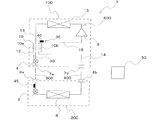
本発明の実施の形態1に係る冷凍サイクル装置1について説明する。図1は、本実施の形態1に係る冷凍サイクル装置1の一例を示す概略的な冷媒回路図である。なお、図1を含む以下の図面では各構成部材の寸法の関係及び形状が、実際のものとは異なる場合がある。
The
図1に示すように、冷凍サイクル装置1は、熱源側ユニット100(例えば、室外機)と、熱源側ユニット100に対し並列に配置された負荷側ユニット200(例えば、室内機)とを備える。熱源側ユニット100と負荷側ユニット200との間は、現地配管である第1の連絡配管300(液配管)及び第2の連絡配管400(ガス配管)で接続されている。なお、図1の冷凍サイクル装置1は、負荷側ユニット200を1台接続した構成としているが、負荷側ユニット200を複数台接続した構成としてもよい。
As shown in FIG. 1, the
本実施の形態1の冷凍サイクル装置1は、第1の圧縮機2と、第1の熱源側熱交換器3と、第1の熱源側減圧装置4と、負荷側減圧装置5と、負荷側熱交換器6とを冷媒配管を介して接続し、第1の冷媒を循環させる第1の冷凍サイクル500を備えている。なお、第1の冷凍サイクル500を循環する第1の冷媒は、冷凍サイクル装置1の用途に応じて任意の種類の冷媒を選択することが可能である。例えば、本実施の形態1の冷凍サイクル装置1では、CO2等の自然冷媒、R32等のハイドロフルオロカーボン、2,3,3,3−テトラフルオロ−1−プロペン(HFO−1234yf)等のハイドロフルオロオレフィン、R410A等の混合溶媒を第1の冷媒として使用することができる。The
第1の圧縮機2は、熱源側ユニット100に収容され、吸入した低圧の第1の冷媒を圧縮し、高圧の第1の冷媒として吐出する周波数可変型の流体機械である。第1の圧縮機2は、例えば、インバータにより回転周波数が制御されるスクロール圧縮機を用いることができる。
The
第1の熱源側熱交換器3は、本実施の形態1においては、放熱器(凝縮器)として機能する熱交換器であり、熱源側ユニット100に収容されている。本実施の形態1においては、第1の熱源側熱交換器3は、第1の熱源側熱交換器3の内部を流れる第1の冷媒と、熱源側熱交換器用ファン(図示せず)によって送風される外気(例えば、室外空気)との熱交換を行うように構成される。第1の熱源側熱交換器3は、例えば、伝熱管と複数のフィンとにより構成されたクロスフィン式のフィン・アンド・チューブ型熱交換器として構成される。
In the first embodiment, the first heat source
第1の熱源側減圧装置4は、本実施の形態1においては、第1の熱源側熱交換器3から流入する高圧液冷媒を膨張及び減圧させて、現地配管である第1の連絡配管300の設計圧未満の第1の冷媒として、第1の連絡配管300に流入させるものである。例えば、第1の連絡配管300の設計圧は、第1の連絡配管300の耐圧基準値に設定される。第1の熱源側減圧装置4は、熱源側ユニット100に収容され、例えば多段階又は連続的に開度を調節可能なリニア電子膨張弁(LEV)等の電子膨張弁として構成される。
In the first embodiment, the first heat-source-
負荷側減圧装置5は、本実施の形態1においては、第1の連絡配管300から流入する第1の連絡配管300の設計圧未満の第1の冷媒を更に膨張及び減圧させて、負荷側熱交換器6に流入させるものである。負荷側減圧装置5は、負荷側ユニット200に収容されており、例えば多段階又は連続的に開度を調節可能なリニア電子膨張弁等の電子膨張弁として構成される。
In the first embodiment, the load-
負荷側熱交換器6は、本実施の形態1においては、蒸発器(冷却器)として機能する熱交換器であり、負荷側ユニット200に収容されている。負荷側熱交換器6は、例えば、負荷側熱交換器6の内部を流れる冷媒と、外気(例えば、室内空気)との熱交換を行うように構成される。負荷側熱交換器6は、例えば、伝熱管と複数のフィンとにより構成されたクロスフィン式のフィン・アンド・チューブ型熱交換器として構成できる。また、負荷側熱交換器6は、負荷側熱交換器用ファン(図示せず)からの送風によって、外気が供給されるように構成してもよい。
The load-
以降では、負荷側熱交換器6が蒸発器として機能する冷凍サイクル装置1の運転動作を「冷房運転」と称する。
Hereinafter, the operation operation of the
熱源側ユニット100に収容され、第1の熱源側減圧装置4と第1の連絡配管300との間に配置されている冷媒配管には、第1の連絡配管300と接続するための第1の熱源側接続バルブ7aが設けられている。熱源側ユニット100に収容され、第1の圧縮機2と第2の連絡配管400との間に配置された熱源側冷媒配管には、第2の連絡配管400と接続するための第2の熱源側接続バルブ7bが設けられている。負荷側ユニット200に収容され、負荷側減圧装置5と第1の連絡配管300との間に配置された負荷側冷媒配管には、第1の連絡配管300と接続するための第1の負荷側接続バルブ8aが設けられている。負荷側ユニット200に収容され、負荷側熱交換器6と第2の連絡配管400との間に配置された負荷側冷媒配管には、第2の連絡配管400と接続するための第2の負荷側接続バルブ8bが設けられている。第1の熱源側接続バルブ7a、第2の熱源側接続バルブ7b、第1の負荷側接続バルブ8a、及び第2の負荷側接続バルブ8bは、例えば、開放及び閉止の切り替えが可能な二方向電磁弁等の二方弁で構成されている。
The refrigerant pipe which is housed in the heat
次に、本実施の形態1の冷凍サイクル装置1における、過冷却熱交換器10及び第2の熱源側減圧装置20について説明する。
Next, the
過冷却熱交換器10は、前記第1の熱源側熱交換器3と前記第1の熱源側減圧装置4との間に配置されている。過冷却熱交換器10は、第1の伝熱管10aと第2の伝熱管10bとを有しており、熱源側ユニット100に収容されている。本実施の形態1では、過冷却熱交換器10は、冷房運転時において、第1の伝熱管10aを流れる高圧の第1の冷媒と、第2の伝熱管10bを流れる減圧された第1の冷媒との間で熱交換を行う熱交換器である。過冷却熱交換器10は、例えば、第1の伝熱管10aと第2の伝熱管10bと複数のフィンとにより構成されたクロスフィン式のフィン・アンド・チューブ型熱交換器として構成できる。
The
第1の伝熱管10aの一方の端部と第1の熱源側減圧装置4とは、第1の熱源側冷媒配管12で接続されている。第1の伝熱管10aの他の一方の端部と第1の熱源側熱交換器3とは、第2の熱源側冷媒配管13で接続されている。第1の熱源側冷媒配管12に配置された分岐接続部12aと、第2の伝熱管10bの一方の端部とは、第1の熱源側分岐冷媒配管16で接続されている。第2の伝熱管10bの他の一方の端部と、第1の圧縮機2の中圧部分とは、第2の熱源側分岐冷媒配管18で接続されている。なお、第1の熱源側冷媒配管12及び第2の熱源側冷媒配管13は、第1の冷凍サイクル500を構成する冷媒配管の一部である。また、第1の熱源側冷媒配管12、第2の熱源側冷媒配管13、第1の熱源側分岐冷媒配管16、及び第2の熱源側分岐冷媒配管18は、熱源側ユニット100に収容されている。
One end of the first
第2の熱源側減圧装置20は、第1の熱源側分岐冷媒配管16に配置されている。第2の熱源側減圧装置20は、第1の熱源側冷媒配管12から第1の熱源側分岐冷媒配管16に分岐して流入する高圧液冷媒を膨張及び減圧させて、第2の伝熱管10bに流入させるものである。第2の熱源側減圧装置20は、熱源側ユニット100に収容され、例えば多段階又は連続的に開度を調節可能なリニア電子膨張弁(LEV)等の電子膨張弁として構成される。
The second heat source
次に、本実施の形態1に係る冷凍サイクル装置1に配置されるセンサについて説明する。
Next, the sensor arranged in the
本実施の形態1に係る冷凍サイクル装置1は、第1の温度センサ30と、第2の温度センサ35と、第1の圧力センサ40と、第2の圧力センサ45とを備える。
The
第1の温度センサ30は、第1の熱源側冷媒配管12の上の、分岐接続部12aと第1の熱源側減圧装置4との間に配置されている。第1の温度センサ30は、冷房運転時において、過冷却熱交換器10の第1の伝熱管10aから流出し、第1の熱源側減圧装置4に流入する第1の冷媒の温度を冷媒配管を介して検知する温度センサである。
The
第2の温度センサ35は、第2の熱源側分岐冷媒配管18に配置されている。第2の温度センサ35は、冷房運転時において、過冷却熱交換器10の第2の伝熱管10bから流出し、第1の圧縮機2の中圧部分に注入される第1の冷媒の温度を冷媒配管を介して検知する温度センサである。
The
第1の温度センサ30及び第2の温度センサ35の材料としては、半導体(例えば、サーミスタ)又は金属(例えば、測温抵抗体)等が用いられる。なお、第1の温度センサ30及び第2の温度センサ35は、同一の材料で構成してもよいし、異なる材料で構成してもよい。
As a material for the
第1の圧力センサ40は、第2の熱源側分岐冷媒配管18に配置されている。第1の圧力センサ40は、冷房運転時において、過冷却熱交換器10の第2の伝熱管10bから流出し、第1の圧縮機2の中圧部分に注入される第1の冷媒の圧力を検知する圧力センサである。
The
第2の圧力センサ45は、負荷側ユニット200に収容され、第1の負荷側接続バルブ8aと負荷側減圧装置5との間に配置された負荷側冷媒配管に配置されている。第2の圧力センサ45は、冷房運転時において、第1の連絡配管300を通って第2の圧力センサ45に流入する第1の冷媒の圧力を検知する圧力センサである。
The
第1の圧力センサ40及び第2の圧力センサ45としては、水晶圧電式圧力センサ、半導体センサ、又は圧力トランスデューサ等が用いられる。なお、第1の圧力センサ40及び第2の圧力センサ45は、同種類のもので構成してもよいし、異なる種類のもので構成してもよい。
As the
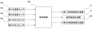
次に、本実施の形態1に係る制御装置50について図2を用いて説明する。図2は、本実施の形態1に係る冷凍サイクル装置1の制御装置50における制御の一部を表現した制御ブロック図である。
Next, the
本実施の形態1に係る制御装置50は、第1の冷凍サイクル500を制御するものであり、CPU、メモリ(例えば、ROM、RAM等)、I/Oポート等を備えたマイクロコンピュータを有している。図2に示すように、本実施の形態1に係る制御装置50は、制御装置50は、第1の温度センサ30及び第2の温度センサ35で検知した温度情報の電気信号、並びに第1の圧力センサ40及び第2の圧力センサ45で検知した圧力情報の電気信号を受信するように構成される。制御装置50は、温度情報の電気信号及び圧力情報の電気信号に応じた制御信号を、第1の熱源側減圧装置4、負荷側減圧装置5、及び第2の熱源側減圧装置20に送信する。第1の熱源側減圧装置4では、送信された制御信号に応じて、第1の熱源側減圧装置4の開度が調整される。負荷側減圧装置5では、送信された制御信号に応じて、負荷側減圧装置5の開度が調整される。第2の熱源側減圧装置20では、送信された制御信号に応じて、第2の熱源側減圧装置20の開度が調整される。また、制御装置50は、第1の冷凍サイクル500の他の構成要素の制御を行うように構成できる。例えば、制御装置50は、熱源側ユニット100及び負荷側ユニット200の運転の開始及び停止、第1の圧縮機2の運転周波数の調整等の運転状態を制御できるように構成できる。
The
制御装置50は、第1の連絡配管300の設計圧等の各種データを記憶できる記憶部(図示せず)を有するように構成される。また、制御装置50は、第1の連絡配管300の設計圧等の各種データを入力可能なインタフェース部(図示せず)を有するように構成できる。
The
次に、本実施の形態1に係る冷凍サイクル装置1の冷房運転時の動作について説明する。
Next, the operation of the
第1の冷媒は、第1の圧縮機2から高温高圧のガス冷媒として吐出され、第1の熱源側熱交換器3へ流入する。第1の熱源側熱交換器3に流入した高温高圧のガス冷媒は、室外空気等の低温の媒体に熱を放出することによって熱交換され、第1の冷媒は高圧の液冷媒となる。
The first refrigerant is discharged from the
高圧の液冷媒は、過冷却熱交換器10の第1の伝熱管10aに流入し、第2の伝熱管10bを流れる第1の冷媒と熱交換されて過冷却され、第1の冷媒は、過冷却された高圧の液冷媒となる。本実施の形態1の冷凍サイクル装置1においては、第2の伝熱管10bを流れる第1の冷媒は、第1の熱源側冷媒配管12の分岐接続部12aで分流され、第1の熱源側分岐冷媒配管16に流入し、第2の熱源側減圧装置20によって、膨張及び減圧された(例えば、中圧の)液冷媒又は二相冷媒である。第2の伝熱管10bから流出した第1の冷媒は、第2の熱源側分岐冷媒配管18を経由して、第1の圧縮機2の中圧部分に注入される。
The high-pressure liquid refrigerant flows into the first
過冷却熱交換器10で過冷却された高圧の液冷媒は、第1の熱源側減圧装置4に流入し、第1の熱源側減圧装置4で膨張及び減圧されて、第1の冷媒は、減圧された(例えば、中圧の)液冷媒又は二相冷媒となる。減圧された液冷媒又は二相冷媒は、熱源側ユニット100から流出し、第1の連絡配管300を経由して、負荷側ユニット200に流入する。
The high-pressure liquid refrigerant supercooled by the supercooling
負荷側ユニット200に流入した減圧された液冷媒又は二相冷媒は、負荷側減圧装置5に流入する。負荷側減圧装置5に流入した減圧された液冷媒又は二相冷媒は、更に膨張及び減圧されて、第1の冷媒は、低温低圧の二相冷媒となる。低温低圧の二相冷媒は、負荷側熱交換器6に流入し、室内空気等の高温の媒体から熱を吸収し、第1の冷媒は、蒸発して乾き度の高い二相冷媒又は低温低圧のガス冷媒となる。負荷側熱交換器6から流出した乾き度の高い二相冷媒又は低温低圧のガス冷媒は、負荷側ユニット200から流出し、第2の連絡配管400を経由して、熱源側ユニット100に流入する。負荷側ユニット200に流入した乾き度の高い二相冷媒又は低温低圧のガス冷媒は、第1の圧縮機2に吸入される。第1の圧縮機2に吸入された冷媒は圧縮されて、第1の冷媒は、高温高圧のガス冷媒となり、第1の圧縮機2から吐出される。冷凍サイクル装置1の冷房運転では以上のサイクルが繰り返される。
The depressurized liquid refrigerant or two-phase refrigerant that has flowed into the load-
次に、本実施の形態1に係る冷凍サイクル装置1の制御装置50における制御処理を説明する。
Next, a control process in the
本実施の形態1に係る冷凍サイクル装置1の制御装置50は、第1の熱源側減圧装置4の開度を調整して、圧力が第1の連絡配管300の設計圧未満の液冷媒として、第1の冷媒を第1の連絡配管300に流入させるように構成される。
The
また、本実施の形態1に係る冷凍サイクル装置1の制御装置50は、冷房運転時において、第2の熱源側減圧装置20の開度を調整して過冷却度を大きくし、第1の熱源側減圧装置4に流入する前記第1の冷媒の温度が、設計圧における第1の冷媒の飽和液温度よりも低くなるように構成できる。
Further, the
以降の本実施の形態1の制御処理の説明では、第1の熱源側減圧装置4の開度DH1は、0≦DH≦1の範囲で調整可能なものとする。開度DH1=0の状態は、第1の熱源側減圧装置4が閉止状態であることを示し、開度DH1=1の状態は、第1の熱源側減圧装置4が全開放状態であることを示す。
In the following description of the control process of the first embodiment, it is assumed that the opening degree DH1 of the first heat-source-
また、第2の熱源側減圧装置20の開度DH2は、0≦DH2≦1の範囲で調整可能なものとする。開度DH2=0の状態は、第2の熱源側減圧装置20が閉止状態であることを示し、開度DH2=1の状態は、第2の熱源側減圧装置20が全開放状態であることを示す。
In addition, the opening degree DH2 of the second heat source
図3は、本実施の形態1に係る冷凍サイクル装置1の制御装置50における、冷房運転時の制御処理の一例を示すフローチャートである。図3の制御処理は、冷房運転時に常時行うようにしてもよいし、例えば、第1の圧縮機2の周波数変動等の冷凍サイクル装置1のパラメータの変動を検知した際に随時行うようにしてもよい。
FIG. 3 is a flowchart showing an example of the control process during the cooling operation in the
本実施の形態1においては、制御装置50の記憶部(図示せず)には、第1の連絡配管300の設計圧Pm(例えば、耐圧基準値)のデータが記憶されているものとする。また、制御装置50の記憶部には、冷凍サイクル装置1における第1の冷媒の状態を表すモリエル線図(P−h線図)に関するデータが、例えばテーブル表として記憶されているものとする。
In the first embodiment, it is assumed that the storage unit (not shown) of the
ステップS11においては、第1の温度センサ30で検知される、第1の熱源側減圧装置4に流入する第1の冷媒の温度Tcが、設計圧Pmにおける第1の冷媒の飽和液温度Ta以上であるか否かが制御装置50において判定される。飽和液温度Taは、設計圧Pmの値に基づいて制御装置50で算出される温度値である。
In step S11, the temperature Tc of the first refrigerant flowing into the first heat source-side
第1の冷媒の温度Tcが飽和液温度Ta以上である場合、ステップS12において、制御装置50は、第2の熱源側減圧装置20の開度DH2を調整値ΔDH2だけ開放するように制御する。ここで、調整値ΔDH2は、第2の熱源側減圧装置20の構造等の仕様を考慮して任意に定められる定数であり、例えば、調整値ΔDH2は0.02とすることができる。その後、第1の冷媒の温度Tcが飽和液温度Taより小さくなるまで、制御装置50では、ステップS12の制御処理が繰り返される。
When the temperature Tc of the first refrigerant is equal to or higher than the saturated liquid temperature Ta, in step S12, the
第1の冷媒の温度Tcが飽和液温度Taより小さい場合、ステップS13において、負荷側減圧装置5に流入する第1の冷媒の圧力Pが、飽和液圧力Ps以下であるか否かが制御装置50において判定される。ここで、負荷側減圧装置5に流入する第1の冷媒の圧力Pは、第2の圧力センサ45で検知される。飽和液圧力Psは、第1の冷媒の温度Tcの値に基づいて制御装置50で算出される圧力値であり、モリエル線図上では、第1の冷媒の温度Tcから等比エンタルピ変化させた飽和液線上の点として示される。第1の冷媒の圧力Pが飽和液圧力Psより大きい場合には、制御処理は終了する。
When the temperature Tc of the first refrigerant is lower than the saturated liquid temperature Ta, in step S13, it is determined whether or not the pressure P of the first refrigerant flowing into the load side
第1の冷媒の圧力Pが飽和液圧力Ps以下である場合、ステップS14において、制御装置50は、第1の熱源側減圧装置4の開度DH1を調整値ΔDH1だけ開放するように制御する。ここで、調整値ΔDH1は、第1の熱源側減圧装置4の構造等の仕様を考慮して任意に定められる定数であり、例えば、調整値ΔDH1は0.01とすることができる。その後、第1の冷媒の圧力Pが飽和液圧力Psよりも大きくなるまで、制御装置50では、ステップS14の制御処理が繰り返される。
When the pressure P of the first refrigerant is equal to or lower than the saturated liquid pressure Ps, in step S14, the
次に、本実施の形態1による本発明の効果を説明する。 Next, the effect of the present invention according to the first embodiment will be described.
上述したとおり、本実施の形態1に係る冷凍サイクル装置1は、第1の圧縮機2と、第1の熱源側熱交換器3と、第1の熱源側減圧装置4とを収容する熱源側ユニット100と、負荷側減圧装置5と負荷側熱交換器6とを収容し、第1の熱源側減圧装置4と負荷側減圧装置5との間に配置される第1の連絡配管300、及び第1の圧縮機2と負荷側熱交換器6との間に配置される第2の連絡配管400を介して熱源側ユニット100と接続されている負荷側ユニット200と、制御装置50とを備え、第1の圧縮機2、第1の熱源側熱交換器3、第1の熱源側減圧装置4、負荷側減圧装置5、及び負荷側熱交換器6は、冷媒配管を介して接続され、第1の冷媒を循環させる第1の冷凍サイクル500を構成しており、制御装置50は、負荷側熱交換器6が蒸発器として機能する冷房運転時において、第1の熱源側減圧装置4の開度を調整して、圧力が第1の連絡配管300の設計圧未満の液冷媒として、第1の冷媒を第1の連絡配管300に流入させるものである。
As described above, the
従来の冷凍装置、例えば二元冷凍装置としては、現地液配管に二相冷媒を通過させることにより、冷凍装置の全体冷媒量を低減させて、冷媒コストの低減及び製品コストの低減を図ったものが一般的に知られている。従来の冷凍装置では、現地液配管に二相冷媒を通過させるために、室外ユニットに第1の膨張弁を設け、冷媒を減圧及び膨張させて、現地液配管に二相冷媒を流入させている。また、従来の冷凍装置では、室内ユニットに第2の膨張弁を設け、現地液配管から流入する二相冷媒を更に減圧及び膨張させて、蒸発器として機能する室内側熱交換器に流入させている。以上のように従来の冷凍装置では、第1の膨張弁及び第2の膨張弁を現地液配管の前後に設けた、いわゆる二段絞りの構造を有している。 As a conventional refrigerating device, for example, a dual refrigerating device, by passing a two-phase refrigerant through a local liquid pipe, the total amount of refrigerant in the refrigerating device is reduced to reduce the refrigerant cost and the product cost. Is generally known. In the conventional refrigeration system, a first expansion valve is provided in the outdoor unit to pass the two-phase refrigerant through the on-site liquid piping, decompresses and expands the refrigerant, and causes the two-phase refrigerant to flow into the on-site liquid piping. .. Further, in the conventional refrigeration system, a second expansion valve is provided in the indoor unit to further decompress and expand the two-phase refrigerant flowing from the on-site liquid pipe, and to make it flow into the indoor heat exchanger functioning as an evaporator. There is. As described above, the conventional refrigeration system has a so-called two-stage throttle structure in which the first expansion valve and the second expansion valve are provided before and after the on-site liquid pipe.
しかしながら、従来の冷凍装置では現地液配管に二相冷媒を流入させているため、現地配管での圧損及び騒音が増加するという問題点があった。また、複数の室内側熱交換器が設置された場合(例えば、複数の室内ユニットが設置された場合)に、現地液配管から流入した二相冷媒が室内側熱交換器に均等に分配されず、室内側熱交換器が増加するにつれて冷媒の分配が悪化するという問題点があった。 However, in the conventional refrigeration system, since the two-phase refrigerant flows into the local liquid pipe, there is a problem that pressure loss and noise in the local pipe increase. Also, when multiple indoor heat exchangers are installed (for example, when multiple indoor units are installed), the two-phase refrigerant that has flowed in from the local liquid piping is not evenly distributed to the indoor heat exchangers. However, there has been a problem that the distribution of the refrigerant deteriorates as the number of indoor heat exchangers increases.
これに対し、本実施の形態1の構成によれば、冷房運転時において、第1の熱源側減圧装置4の開度を調整して、圧力が第1の連絡配管300の設計圧未満の液冷媒として、第1の冷媒を第1の連絡配管300に流入させることができる。
On the other hand, according to the configuration of the first embodiment, during cooling operation, the opening degree of the first heat source side
本実施の形態1では、第1の連絡配管300に流入する冷媒を液冷媒とすることができ、第1の連絡配管300での圧力損失及び騒音を低減させることができるため、冷凍サイクル装置1におけるエネルギー消費量を削減することができる。また、第1の連絡配管300から負荷側ユニット200に流入する冷媒が液冷媒となるため、冷凍サイクル装置1に複数の負荷側熱交換器6が設置される場合であっても、冷媒を均等に分配することが可能となる。
In the first embodiment, the refrigerant flowing into the
また、本実施の形態1では、第1の連絡配管300に流入する液冷媒の圧力は、第1の連絡配管300の設計圧未満にできるため、既存の現地配管を流用可能な冷凍サイクル装置1を提供できる。例えば、第1の連絡配管300は、負荷側熱交換器6での冷媒の飽和温度が、負荷側熱交換器6の蒸発温度を下回らない範囲で第1の冷媒の圧力損失が生じるものであれば流用可能である。
In addition, in the first embodiment, the pressure of the liquid refrigerant flowing into the
また、本実施の形態1に係る冷凍サイクル装置1においては、熱源側ユニット100は、第1の熱源側熱交換器3と第1の熱源側減圧装置4との間に配置され、第1の伝熱管10aと第2の伝熱管10bとを有する過冷却熱交換器10と、第1の伝熱管10aの一方の端部と第1の熱源側減圧装置4とを接続する第1の熱源側冷媒配管12と、第1の伝熱管10aの他の一方の端部と第1の熱源側熱交換器3とを接続する第2の熱源側冷媒配管13と、第1の熱源側冷媒配管12に配置された分岐接続部12aと、第2の伝熱管10bの一方の端部とを接続する第1の熱源側分岐冷媒配管16と、第2の伝熱管10bの他の一方の端部と、第1の圧縮機2の中圧部分とを接続する第2の熱源側分岐冷媒配管18と、第1の熱源側分岐冷媒配管16に配置された第2の熱源側減圧装置20とを更に備えており、過冷却熱交換器10は、冷房運転時において、第1の伝熱管10aを流れる第1の冷媒と、第2の伝熱管10bを流れる第1の冷媒との間で熱交換を行うものであり、制御装置50は、冷房運転時において、第2の熱源側減圧装置20の開度を調整して過冷却度を大きくし、第1の熱源側減圧装置4に流入する第1の冷媒の温度を、設計圧における第1の冷媒の飽和液温度よりも低くすることができる。
In addition, in the
上述の構成によれば、第1の熱源側減圧装置4に流入する第1の冷媒の温度を、設計圧における第1の冷媒の飽和液温度よりも低くすることができるため、第1の熱源側減圧装置4で減圧及び膨張後も、第1の冷媒を液状態に維持することが容易となる。
According to the above configuration, the temperature of the first refrigerant flowing into the first heat source-side
図4は、本実施の形態1に係る冷凍サイクル装置1の動作を示すモリエル線図である。図4のモリエル線図における縦軸は絶対圧力(MPa)であり、横軸は比エンタルピ(kJ/kg)である。図4には、飽和液線と飽和蒸気線と、第1の冷凍サイクル500における各行程が示されており、説明のために、膨張行程の対応する位置に、第1の熱源側減圧装置4及び負荷側減圧装置5を概略的に表示している。また、図4のモリエル線図には、一点鎖線の折れ線で、第2の熱源側減圧装置20で減圧及び膨張され、過冷却熱交換器10の第2の伝熱管10bで熱交換された冷媒の状態を示している。
FIG. 4 is a Mollier diagram showing the operation of the
また、図4のモリエル線図上のA点は、設計圧Pmから算出される第1の冷媒の飽和液温度Taの位置を示したものである。図4のモリエル線図上のB点は、A点と等比エンタルピとなる第1の冷凍サイクル500の凝縮工程における位置を示したものである。図4のモリエル線図上のC点は、第1の冷凍サイクル500の凝縮工程における、第1の熱源側減圧装置4に流入する第1の冷媒の温度Tcの位置を示したものである。図4のモリエル線図上のD点は、C点と等比エンタルピであり、かつ、圧力が設計圧Pmとなる第1の冷凍サイクル500の膨張行程における位置を示したものである。図4のモリエル線図上のE点は、第1の冷凍サイクル500の膨張行程を示す直線と、飽和液線との交点を示したものであり、第1の冷媒の圧力が飽和液圧力Psとなる位置である。
Further, point A on the Mollier diagram of FIG. 4 indicates the position of the saturated liquid temperature Ta of the first refrigerant calculated from the design pressure Pm. Point B on the Mollier diagram in FIG. 4 indicates the position in the condensation process of the
上述の構成によれば、第2の熱源側減圧装置20の開度を調整して、過冷却熱交換器10で、第1の伝熱管10aを流れる第1の冷媒と、第2の伝熱管10bを流れる第1の冷媒との間で熱交換を行い、過冷却度を大きくすることができる。すなわち、上述の構成によれば、図4のモリエル線図においては、C点は、B点の左側に位置するように調整することができる。B点における第1の冷媒の温度は、A点における飽和液温度Taと同一かわずかに高温となるため、C点がB点の左側に位置する場合は、第1の熱源側減圧装置4に流入する第1の冷媒の温度Tcは、必ず飽和液温度Taよりも低くなる。
According to the above configuration, the opening degree of the second heat source
したがって、上述の構成によれば、第1の連絡配管300に流入する第1の冷媒の圧力Pを、飽和液圧力Psよりも大きく、設計圧Pmよりも小さい状態に、第1の熱源側減圧装置4の開度を調整することによって制御できる。図4のモリエル線図においては、第1の冷媒の圧力Pが、飽和液圧力Psよりも大きく、設計圧Pmよりも小さい状態は、図4の点Dと点Eとの間の膨張行程の位置に対応している。
Therefore, according to the above-described configuration, the pressure P of the first refrigerant flowing into the
具体的には、第1の連絡配管300(現地配管)の設計圧が1.64MPaの場合、点Aは38℃となり、凝縮温度を50℃とすると、過冷却度は約30℃程度のため、点Cは20℃となる。したがって、第1の連絡配管300で冷媒を設計圧以下かつ液状態とするためには、第1の熱源側減圧装置4で1.00MPa〜1.64MPaに制御すればよい。
Specifically, when the design pressure of the first communication pipe 300 (on-site pipe) is 1.64 MPa, the point A is 38°C, and the condensation temperature is 50°C, the degree of supercooling is about 30°C. The point C is 20°C. Therefore, in order to bring the refrigerant into the liquid state below the design pressure in the
以上のとおり、本実施の形態1に係る構成によれば、第1の熱源側減圧装置4に流入する第1の冷媒の温度Tcを飽和液温度Ta未満とすることで、第1の熱源側減圧装置4で減圧及び膨張後も、第1の冷媒は液状態を維持することができる。
As described above, according to the configuration of the first embodiment, the temperature Tc of the first refrigerant flowing into the first heat source-side
実施の形態2.
本発明の実施の形態2は、上述の実施の形態1に係る冷凍サイクル装置1の変形例である。図5は、本実施の形態2に係る冷凍サイクル装置1の一例を示す概略的な冷媒回路図である。
The second embodiment of the present invention is a modification of the
本実施の形態2の冷凍サイクル装置1の熱源側ユニット100は、上述の実施の形態1に係る冷凍サイクル装置1の第1の熱源側分岐冷媒配管16の代わりに、第2の連絡配管400と過冷却熱交換器10の第2の伝熱管10bの一方の端部との間に接続される第3の熱源側冷媒配管14を備えている。また、本実施の形態2の冷凍サイクル装置1の熱源側ユニット100は、上述の実施の形態1に係る冷凍サイクル装置1の第2の熱源側分岐冷媒配管18の代わりに、過冷却熱交換器10の第2の伝熱管10bの他方の端部と第1の圧縮機2との間に接続される第4の熱源側冷媒配管15とを更に備えている。また、本実施の形態2の冷凍サイクル装置1の熱源側ユニット100は、第2の熱源側減圧装置20を有していない。また、第2の温度センサ35及び第1の圧力センサ40は、本実施の形態2の冷凍サイクル装置1においては、第4の熱源側冷媒配管15上に設けられている。本実施の形態2の冷凍サイクル装置1の熱源側ユニット100のその他の構造は、上述の実施の形態1に係る冷凍サイクル装置1と同一のものである。
The heat
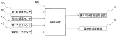
図6は、本実施の形態2に係る冷凍サイクル装置1の制御装置50における制御の一部を表現した制御ブロック図である。図6は、第2の熱源側減圧装置20を有していない点を除けば、図2の制御ブロック図と同一のものである。
FIG. 6 is a control block diagram expressing a part of the control in
次に、本実施の形態2に係る冷凍サイクル装置1の制御装置50における制御処理を説明する。
Next, a control process in the
本実施の形態2に係る冷凍サイクル装置1の制御装置50は、冷房運転時において、前記負荷側減圧装置の開度を調整して過冷却度を大きくし、前記第1の熱源側減圧装置に流入する前記第1の冷媒の温度を、前記設計圧における前記第1の冷媒の飽和液温度よりも低くするように構成される。
The
以降の本実施の形態2の制御処理の説明では、第1の熱源側減圧装置4の開度DH1は、0≦DH≦1の範囲で調整可能なものとする。開度DH1=0の状態は、第1の熱源側減圧装置4が閉止状態であることを示し、開度DH1=1の状態は、第1の熱源側減圧装置4が全開放状態であることを示す。
In the following description of the control process of the second embodiment, it is assumed that the opening degree DH1 of the first heat-source-
また、負荷側減圧装置5の開度DLは、0≦DL≦1の範囲で調整可能なものとする。開度DL=0の状態は、負荷側減圧装置5が閉止状態であることを示し、開度DL=1の状態は、負荷側減圧装置5が全開放状態であることを示す。
Further, the opening degree DL of the load side
図7は、本実施の形態2に係る冷凍サイクル装置1の制御装置50における、冷房運転時の制御処理の一例を示すフローチャートである。図7の制御処理は、図3の制御処理と同様に、冷房運転時に常時行うようにしてもよいし、例えば、第1の圧縮機2の周波数変動等の冷凍サイクル装置1のパラメータの変動を検知した際に随時行うようにしてもよい。
FIG. 7 is a flowchart showing an example of the control process during the cooling operation in the
本実施の形態2においても、上述の実施の形態1と同様に制御装置50の記憶部(図示せず)には、第1の連絡配管300の設計圧Pm(例えば、耐圧基準値)のデータが記憶されているものとする。また、制御装置50の記憶部には、冷凍サイクル装置1における第1の冷媒の状態を表すモリエル線図(P−h線図)に関するデータが、例えばテーブル表として記憶されているものとする。
Also in the second embodiment, similar to the above-described first embodiment, data of the design pressure Pm (for example, withstand pressure reference value) of the
ステップS21では、上述の実施の形態1のステップS11と同様に、第1の温度センサ30で検知される、第1の熱源側減圧装置4に流入する第1の冷媒の温度Tcが、設計圧Pmにおける第1の冷媒の飽和液温度Ta以上であるか否かが制御装置50において判定される。
In step S21, the temperature Tc of the first refrigerant flowing into the first heat source-side
第1の冷媒の温度Tcが飽和液温度Ta以上である場合、ステップS22において、制御装置50は、負荷側減圧装置5の開度DLを調整値ΔDLだけ開放するように制御する。ここで、調整値ΔDLは、負荷側減圧装置5の構造等の仕様を考慮して任意に定められる定数であり、例えば、調整値ΔDH2は0.02とすることができる。その後、第1の冷媒の温度Tcが飽和液温度Taより小さくなるまで、制御装置50では、ステップS22の制御処理が繰り返される。
When the temperature Tc of the first refrigerant is equal to or higher than the saturated liquid temperature Ta, in step S22, the
ステップS23では、上述の実施の形態1のステップS13と同様に、第1の冷媒の温度Tcが飽和液温度Taより小さい場合、負荷側減圧装置5に流入する第1の冷媒の圧力Pが、飽和液圧力Ps以下であるか否かが制御装置50において判定される。第1の冷媒の圧力Pが飽和液圧力Psより大きい場合には、制御処理は終了する。
In step S23, when the temperature Tc of the first refrigerant is lower than the saturated liquid temperature Ta, the pressure P of the first refrigerant flowing into the load side
ステップS24では、上述の実施の形態1のステップS14と同様に、第1の冷媒の圧力Pが飽和液圧力Ps以下である場合に、制御装置50は、第1の熱源側減圧装置4の開度DH1を調整値ΔDH1だけ開放するように制御する。
In step S24, the
本実施の形態2の冷凍サイクル装置1の熱源側ユニット100は、第1の熱源側熱交換器3と第1の熱源側減圧装置4との間に配置され、第1の伝熱管10aと第2の伝熱管10bとを有する過冷却熱交換器10と、第1の伝熱管10aの一方の端部と第1の熱源側減圧装置4とを接続する第1の熱源側冷媒配管12と、第1の伝熱管10aの他の一方の端部と第1の熱源側熱交換器3とを接続する第2の熱源側冷媒配管13と、第2の連絡配管400と第2の伝熱管10bの一方の端部との間に接続される第3の熱源側冷媒配管14と、第2の伝熱管10bの他方の端部と第1の圧縮機2との間に接続される第4の熱源側冷媒配管15とを更に備え、過冷却熱交換器10は、冷房運転時において、第1の伝熱管10aを流動する第1の冷媒と、第2の伝熱管10bを流動する第1の冷媒との間で熱交換を行うものであり、制御装置50は、冷房運転時において、負荷側減圧装置5の開度を調整して過冷却度を大きくし、第1の熱源側減圧装置4に流入する第1の冷媒の温度を、設計圧における第1の冷媒の飽和液温度よりも低くするものである。
The heat-source-
図8は、本実施の形態2に係る冷凍サイクル装置1の動作を示すモリエル線図である。図8は、過冷却熱交換器10の第2の伝熱管10bで熱交換された冷媒の状態を示す一点鎖線の折れ線が記載されていない点を除けば、図4のモリエル線図と同一である。
FIG. 8 is a Mollier diagram showing the operation of the
本実施の形態2の構成によれば、負荷側減圧装置5の開度を調整して、過冷却熱交換器10で、第1の伝熱管10aを流れる第1の冷媒と、第2の伝熱管10bを流れる第1の冷媒との間で熱交換を行い、過冷却度を大きくすることができる。また、第1の熱源側減圧装置4に流入する第1の冷媒の温度Tcを飽和液温度Ta未満とすることで、第1の熱源側減圧装置4で減圧及び膨張後も、第1の冷媒は液状態を維持することができる。
According to the configuration of the second embodiment, the opening degree of the load-side
また、本実施の形態2の構成によれば、負荷側熱交換器6から流出した乾き度の高い二相冷媒又は低温低圧のガス冷媒が過冷却熱交換器10で更に過熱されるため、第1の圧縮機2への液戻りが回避できる。したがって、本実施の形態2の構成によれば、冷凍サイクル装置1の信頼性を向上させることができる。また、本実施の形態2の構成によれば、冷凍サイクル装置1を流れる全ての第1の冷媒を負荷側熱交換器6での熱交換に用いることができるため、冷凍サイクル装置1の冷却能力を向上させることができる。
Further, according to the configuration of the second embodiment, since the two-phase refrigerant having a high degree of dryness or the low-temperature low-pressure gas refrigerant flowing out from the load-
実施の形態3.
本発明の実施の形態3は、上述の実施の形態1の冷凍サイクル装置1が、第2の冷凍サイクル600を更に備えたものである。図9は、本実施の形態3に係る冷凍サイクル装置1の一例を示す概略的な冷媒回路図である。
In the third embodiment of the present invention, the
本実施の形態3の冷凍サイクル装置1は、上述の実施の形態1の構成に加え、熱源側ユニット100が、第2の圧縮機62と、第2の熱源側熱交換器63と、第3の熱源側減圧装置64と、第1の熱源側熱交換器3とを冷媒配管を介して接続し、第2の冷媒を循環させる第2の冷凍サイクル600を更に備えており、第1の熱源側熱交換器3は、冷房運転時において、第1の圧縮機2から流入する第1の冷媒と、第3の熱源側減圧装置64から流入する第2の冷媒との間で熱交換を行うものであり、第2の熱源側熱交換器は、放熱器として機能するものである。
In the
第2の冷凍サイクル600における第2の圧縮機62、第2の熱源側熱交換器63、及び第3の熱源側減圧装置64の構造及び動作は、第1の圧縮機2、第1の熱源側熱交換器3、及び第1の熱源側減圧装置4と同一である。本実施の形態3においては、第1の熱源側熱交換器3は、上述したように、冷房運転時において、第1の圧縮機2から流入する第1の冷媒と、第3の熱源側減圧装置64から流入する第2の冷媒との間で熱交換を行うカスケード熱交換器として機能する。
The structure and operation of the
本実施の形態3の第2の冷凍サイクル600では、例えば、R32等のハイドロフルオロカーボン、2,3,3,3−テトラフルオロ−1−プロペン(HFO−1234yf)等のハイドロフルオロオレフィン、R410A等の混合溶媒を第2の冷媒として使用することができる。
In the
図10は、本実施の形態3に係る冷凍サイクル装置1の制御装置50における制御の一部を表現した制御ブロック図である。図10は、制御装置50によって第3の熱源側減圧装置64の開度が制御される点を除けば、図2の制御ブロック図と同一のものである。
FIG. 10 is a control block diagram expressing a part of control in
図11は、本実施の形態3に係る冷凍サイクル装置1の制御装置50における、冷房運転時の制御処理の一例を示すフローチャートである。図11の制御処理は、図3の制御処理と同一のものであり、図11のステップS31〜S34は、図3のS11〜S14に対応する。その他の制御処理の内容も、上述の実施の形態1の制御処理と同様である。
FIG. 11 is a flowchart showing an example of the control process during the cooling operation in the
図12は、本実施の形態3に係る冷凍サイクル装置1の動作を示すモリエル線図である。図12は、図4のモリエル線図と同一のものである。
FIG. 12 is a Mollier diagram showing the operation of the
本実施の形態3の構成によっても、上述の実施の形態1と同様に、第2の熱源側減圧装置20の開度を調整して、過冷却熱交換器10で、第1の伝熱管10aを流れる第1の冷媒と、第2の伝熱管10bを流れる第1の冷媒との間で熱交換を行い、過冷却度を大きくすることができる。また、第1の熱源側減圧装置4に流入する第1の冷媒の温度Tcを飽和液温度Ta未満とすることで、第1の熱源側減圧装置4で減圧及び膨張後も、第1の冷媒は液状態を維持することができる。
Also according to the configuration of the third embodiment, the opening degree of the second heat source
また、本実施の形態3の構成により、第1の冷媒としてCO2を使用し、CO2を超臨界状態以下で使用することができるため、安全性に優れた冷凍サイクル装置1を提供できる。Further, the configuration of the third embodiment, using CO 2 as the first refrigerant, for the CO 2 can be used in the following supercritical state can provide a
その他の実施の形態.
上述の実施の形態に限らず種々の変形が可能である。例えば、上述の実施の形態の冷凍サイクル装置1は、例えば、空気調和装置、冷凍機等に用いることができる。Other embodiments.
Various modifications are possible without being limited to the above-mentioned embodiment. For example, the
また、冷凍サイクル装置1を空気調和装置として用いる場合には、暖房運転を行うことができるように構成できる。例えば、冷凍サイクル装置1に冷媒流路切替装置(例えば、四方弁)を設けて、冷房運転時と暖房運転時とを切り替え可能に構成できる。
In addition, when the
また、上述の実施の形態における、第2の温度センサ35及び第1の圧力センサ40を用いて、第2の熱源側減圧装置20又は負荷側減圧装置5の開度を調整して、第1の圧縮機2への液戻り量を抑制するように制御することができる。
In addition, the opening degree of the second heat source side
また、上述の実施の形態は互いに組み合わせて用いることが可能である。 Further, the above-described embodiments can be used in combination with each other.
1 冷凍サイクル装置、2 第1の圧縮機、3 第1の熱源側熱交換器、4 第1の熱源側減圧装置、5 負荷側減圧装置、6 負荷側熱交換器、7a 第1の熱源側接続バルブ、7b 第2の熱源側接続バルブ、8a 第1の負荷側接続バルブ、8b 第2の負荷側接続バルブ、10 過冷却熱交換器、10a 第1の伝熱管、10b 第2の伝熱管、12 第1の熱源側冷媒配管、12a 分岐接続部、13 第2の熱源側冷媒配管、14 第3の熱源側冷媒配管、15 第4の熱源側冷媒配管、16 第1の熱源側分岐冷媒配管、18 第2の熱源側分岐冷媒配管、20 第2の熱源側減圧装置、30 第1の温度センサ、35 第2の温度センサ、40 第1の圧力センサ、45 第2の圧力センサ、50 制御装置、62 第2の圧縮機、63 第3の熱源側熱交換器、64 第3の熱源側減圧装置、100 熱源側ユニット、200 負荷側ユニット、300 第1の連絡配管、400 第2の連絡配管、500 第1の冷凍サイクル、600 第2の冷凍サイクル。
DESCRIPTION OF
Claims (4)
負荷側減圧装置と負荷側熱交換器とを収容し、前記第1の熱源側減圧装置と前記負荷側減圧装置との間に配置される第1の連絡配管、及び前記第1の圧縮機と前記負荷側熱交換器との間に配置される第2の連絡配管を介して前記熱源側ユニットと接続されている負荷側ユニットと、
制御装置と
を備え、
前記第1の圧縮機、前記第1の熱源側熱交換器、前記第1の熱源側減圧装置、前記負荷側減圧装置、及び前記負荷側熱交換器は、冷媒配管を介して接続され、第1の冷媒を循環させる第1の冷凍サイクルを構成しており、
前記熱源側ユニットは、
前記第1の熱源側熱交換器と前記第1の熱源側減圧装置との間に配置され、第1の伝熱管と第2の伝熱管とを有する過冷却熱交換器と、
前記第1の伝熱管の一方の端部と前記第1の熱源側減圧装置とを接続する第1の熱源側冷媒配管と、
前記第1の伝熱管の他の一方の端部と前記第1の熱源側熱交換器とを接続する第2の熱源側冷媒配管と、
前記第1の熱源側冷媒配管に配置された分岐接続部と、前記第2の伝熱管の一方の端部とを接続する第1の熱源側分岐冷媒配管と、
前記第2の伝熱管の他の一方の端部と、前記第1の圧縮機の中圧部分とを接続する第2の熱源側分岐冷媒配管と、
前記第1の熱源側分岐冷媒配管に配置された第2の熱源側減圧装置と
を更に備え、
前記過冷却熱交換器は、
前記負荷側熱交換器が蒸発器として機能する冷房運転時において、前記第1の伝熱管を流れる前記第1の冷媒と、前記第2の伝熱管を流れる前記第1の冷媒との間で熱交換を行うものであり、
前記制御装置は、
前記冷房運転時において、
前記第2の熱源側減圧装置の開度を調整して過冷却度を大きくし、前記第1の熱源側減圧装置に流入する前記第1の冷媒の温度を、前記第1の連絡配管の設計圧における前記第1の冷媒の飽和液温度よりも低くし、
前記第1の熱源側減圧装置の開度を調整して、圧力が前記第1の連絡配管の設計圧未満の液冷媒として、前記第1の冷媒を前記第1の連絡配管に流入させるものである
冷凍サイクル装置。 A heat source side unit that accommodates a first compressor, a first heat source side heat exchanger, and a first heat source side pressure reducing device;
A first communication pipe that houses a load-side pressure reducing device and a load-side heat exchanger, and that is arranged between the first heat-source-side pressure reducing device and the load-side pressure reducing device; and the first compressor. A load side unit connected to the heat source side unit via a second connecting pipe arranged between the load side heat exchanger;
With a control device,
The first compressor, the first heat source side heat exchanger, the first heat source side pressure reducing device, the load side pressure reducing device, and the load side heat exchanger are connected via a refrigerant pipe, 1st refrigerating cycle which circulates the refrigerant of 1 is constituted,
The heat source side unit,
A subcooling heat exchanger that is arranged between the first heat source side heat exchanger and the first heat source side pressure reducing device, and has a first heat transfer tube and a second heat transfer tube;
A first heat source side refrigerant pipe connecting one end of the first heat transfer tube and the first heat source side pressure reducing device;
A second heat source side refrigerant pipe connecting the other end of the first heat transfer tube and the first heat source side heat exchanger;
A first heat source side branch refrigerant pipe connecting the branch connection part arranged in the first heat source side refrigerant pipe and one end of the second heat transfer pipe;
A second heat source side branch refrigerant pipe connecting the other end of the second heat transfer pipe and the intermediate pressure portion of the first compressor;
Further comprising a second heat source side decompression device arranged in the first heat source side branch refrigerant pipe,
The subcooling heat exchanger,
During the cooling operation in which the load-side heat exchanger functions as an evaporator, heat is generated between the first refrigerant flowing through the first heat transfer tube and the first refrigerant flowing through the second heat transfer tube. Exchanges,
The control device is
During the cooling operation,
The degree of supercooling is increased by adjusting the opening degree of the second heat source side pressure reducing device, and the temperature of the first refrigerant flowing into the first heat source side pressure reducing device is determined by designing the first communication pipe. Lower than the saturated liquid temperature of the first refrigerant at pressure,
The opening degree of the first heat source side decompression device is adjusted so that the first refrigerant flows into the first communication pipe as a liquid refrigerant whose pressure is less than the design pressure of the first communication pipe. There is a refrigeration cycle device.
負荷側減圧装置と負荷側熱交換器とを収容し、前記第1の熱源側減圧装置と前記負荷側減圧装置との間に配置される第1の連絡配管、及び前記第1の圧縮機と前記負荷側熱交換器との間に配置される第2の連絡配管を介して前記熱源側ユニットと接続されている負荷側ユニットと、
制御装置と
を備え、
前記第1の圧縮機、前記第1の熱源側熱交換器、前記第1の熱源側減圧装置、前記負荷側減圧装置、及び前記負荷側熱交換器は、冷媒配管を介して接続され、第1の冷媒を循環させる第1の冷凍サイクルを構成しており、
前記熱源側ユニットは、
前記第1の熱源側熱交換器と前記第1の熱源側減圧装置との間に配置され、第1の伝熱管と第2の伝熱管とを有する過冷却熱交換器と、
前記第1の伝熱管の一方の端部と前記第1の熱源側減圧装置とを接続する第1の熱源側冷媒配管と、
前記第1の伝熱管の他の一方の端部と前記第1の熱源側熱交換器とを接続する第2の熱源側冷媒配管と、
前記第2の連絡配管と前記第2の伝熱管の一方の端部との間に接続される第3の熱源側冷媒配管と、
前記第2の伝熱管の他方の端部と前記第1の圧縮機との間に接続される第4の熱源側冷媒配管と
を更に備え、
前記過冷却熱交換器は、
前記負荷側熱交換器が蒸発器として機能する冷房運転時において、前記第1の伝熱管を流動する前記第1の冷媒と、前記第2の伝熱管を流動する前記第1の冷媒との間で熱交換を行うものであり、
前記制御装置は、
前記冷房運転時において、
前記負荷側減圧装置の開度を調整して過冷却度を大きくし、前記第1の熱源側減圧装置に流入する前記第1の冷媒の温度を、前記第1の連絡配管の設計圧における前記第1の冷媒の飽和液温度よりも低くし、
前記第1の熱源側減圧装置の開度を調整して、圧力が前記第1の連絡配管の設計圧未満の液冷媒として、前記第1の冷媒を前記第1の連絡配管に流入させるものである
冷凍サイクル装置。 A heat source side unit containing a first compressor, a first heat source side heat exchanger, and a first heat source side pressure reducing device;
A first communication pipe that houses a load-side pressure reducing device and a load-side heat exchanger, and that is arranged between the first heat-source-side pressure reducing device and the load-side pressure reducing device; and the first compressor. A load side unit connected to the heat source side unit via a second connecting pipe arranged between the load side heat exchanger;
With a control device,
The first compressor, the first heat source side heat exchanger, the first heat source side pressure reducing device, the load side pressure reducing device, and the load side heat exchanger are connected via a refrigerant pipe, 1st refrigerating cycle which circulates the refrigerant of 1 is constituted,
The heat source side unit,
A subcooling heat exchanger that is arranged between the first heat source side heat exchanger and the first heat source side pressure reducing device, and has a first heat transfer tube and a second heat transfer tube;
A first heat source side refrigerant pipe connecting one end of the first heat transfer tube and the first heat source side pressure reducing device;
A second heat source side refrigerant pipe that connects the other end of the first heat transfer tube and the first heat source side heat exchanger;
A third heat source side refrigerant pipe connected between the second communication pipe and one end of the second heat transfer pipe;
Further comprising a fourth heat source side refrigerant pipe connected between the other end of the second heat transfer tube and the first compressor,
The subcooling heat exchanger,
Between the first refrigerant flowing through the first heat transfer tube and the first refrigerant flowing through the second heat transfer tube during the cooling operation in which the load-side heat exchanger functions as an evaporator. To exchange heat with
The control device is
During the cooling operation,
The opening degree of the load-side pressure reducing device is adjusted to increase the degree of supercooling, and the temperature of the first refrigerant flowing into the first heat source-side pressure reducing device is set to the design pressure of the first communication pipe as described above. Lower than the saturated liquid temperature of the first refrigerant,
The opening degree of the first heat source side decompression device is adjusted so that the first refrigerant flows into the first communication pipe as a liquid refrigerant having a pressure lower than the design pressure of the first communication pipe. There is a refrigeration cycle device.
第2の圧縮機と、第2の熱源側熱交換器と、第3の熱源側減圧装置と、前記第1の熱源側熱交換器とを冷媒配管を介して接続し、第2の冷媒を循環させる第2の冷凍サイクル The second compressor, the second heat source side heat exchanger, the third heat source side decompression device, and the first heat source side heat exchanger are connected via a refrigerant pipe to connect the second refrigerant. Second refrigeration cycle to circulate
を更に備えており、Is further equipped with,
前記第1の熱源側熱交換器は、 The first heat source side heat exchanger,
前記冷房運転時において、前記第1の圧縮機から流入する第1の冷媒と、前記第3の熱源側減圧装置から流入する第2の冷媒との間で熱交換を行うものであり、 During the cooling operation, heat is exchanged between the first refrigerant flowing from the first compressor and the second refrigerant flowing from the third heat-source-side pressure reducing device,
前記第2の熱源側熱交換器は、 The second heat source side heat exchanger,
前記冷房運転時において、放熱器として機能するものである It functions as a radiator during the cooling operation.
請求項1又は2に記載の冷凍サイクル装置。 The refrigeration cycle apparatus according to claim 1.
請求項1〜3のいずれか1項に記載の冷凍サイクル装置。 Refrigeration cycle apparatus according to any one of claims 1 to 3, wherein the first refrigerant is CO 2.
Applications Claiming Priority (1)
| Application Number | Priority Date | Filing Date | Title |
|---|---|---|---|
| PCT/JP2015/067652 WO2016203624A1 (en) | 2015-06-18 | 2015-06-18 | Refrigeration cycle device |
Publications (2)
| Publication Number | Publication Date |
|---|---|
| JPWO2016203624A1 JPWO2016203624A1 (en) | 2018-01-18 |
| JP6735744B2 true JP6735744B2 (en) | 2020-08-05 |
Family
ID=57546402
Family Applications (1)
| Application Number | Title | Priority Date | Filing Date |
|---|---|---|---|
| JP2017524243A Active JP6735744B2 (en) | 2015-06-18 | 2015-06-18 | Refrigeration cycle equipment |
Country Status (3)
| Country | Link |
|---|---|
| EP (2) | EP3457049B1 (en) |
| JP (1) | JP6735744B2 (en) |
| WO (1) | WO2016203624A1 (en) |
Families Citing this family (8)
| Publication number | Priority date | Publication date | Assignee | Title |
|---|---|---|---|---|
| CN107843037B (en) * | 2017-10-31 | 2021-02-23 | 广东美的暖通设备有限公司 | Multi-split air conditioning system and supercooling control device and method thereof |
| US10655878B2 (en) * | 2018-07-06 | 2020-05-19 | Johnson Controls Technology Company | Variable refrigerant flow system with sub-cooling temperature optimization using extremum-seeking control |
| US11828507B2 (en) | 2018-09-25 | 2023-11-28 | Hangzhou Sanhua Research Institute Co., Ltd. | Air conditioning system and control method therefor |
| CN110953699B (en) * | 2018-09-26 | 2021-05-18 | 杭州三花研究院有限公司 | Air conditioning system and control method thereof |
| JP7469583B2 (en) * | 2019-06-12 | 2024-04-17 | ダイキン工業株式会社 | air conditioner |
| DE102020122713A1 (en) | 2020-08-31 | 2022-03-03 | Andreas Bangheri | Heat pump and method for operating a heat pump |
| CN112033040B (en) * | 2020-09-15 | 2022-08-30 | 广东美的暖通设备有限公司 | Control method of air conditioning system and computer-readable storage medium |
| EP4257892A1 (en) * | 2020-12-01 | 2023-10-11 | Daikin Industries, Ltd. | Refrigeration cycle system |
Family Cites Families (17)
| Publication number | Priority date | Publication date | Assignee | Title |
|---|---|---|---|---|
| JP4407012B2 (en) * | 2000-06-06 | 2010-02-03 | ダイキン工業株式会社 | Refrigeration equipment |
| JP2003139422A (en) * | 2001-10-31 | 2003-05-14 | Daikin Ind Ltd | Refrigerating machine |
| JP2003279170A (en) * | 2002-03-20 | 2003-10-02 | Sanyo Electric Co Ltd | Air conditioning device |
| JP2004190917A (en) * | 2002-12-10 | 2004-07-08 | Sanyo Electric Co Ltd | Refrigeration device |
| JP3966262B2 (en) * | 2003-09-29 | 2007-08-29 | 三菱電機株式会社 | Freezer refrigerator |
| JP5593618B2 (en) * | 2008-02-28 | 2014-09-24 | ダイキン工業株式会社 | Refrigeration equipment |
| JP2011012825A (en) * | 2009-06-30 | 2011-01-20 | Sanyo Electric Co Ltd | Control device for air conditioner |
| JP5452138B2 (en) * | 2009-09-01 | 2014-03-26 | 三菱電機株式会社 | Refrigeration air conditioner |
| JP5537906B2 (en) * | 2009-11-13 | 2014-07-02 | 三菱電機株式会社 | Air conditioner |
| JP5582773B2 (en) * | 2009-12-10 | 2014-09-03 | 三菱重工業株式会社 | Air conditioner and refrigerant amount detection method for air conditioner |
| JP2011242048A (en) * | 2010-05-18 | 2011-12-01 | Mitsubishi Electric Corp | Refrigerating cycle device |
| JP5627417B2 (en) * | 2010-11-26 | 2014-11-19 | 三菱電機株式会社 | Dual refrigeration equipment |
| JP5991989B2 (en) * | 2011-11-29 | 2016-09-14 | 三菱電機株式会社 | Refrigeration air conditioner |
| JP5957232B2 (en) * | 2012-01-30 | 2016-07-27 | 株式会社日本クライメイトシステムズ | Air conditioner for vehicles |
| EP2765370A1 (en) * | 2013-02-08 | 2014-08-13 | Panasonic Corporation | Refrigeration cycle apparatus and hot water generator provided with the same |
| WO2014181399A1 (en) * | 2013-05-08 | 2014-11-13 | 三菱電機株式会社 | Binary refrigeration device |
| JPWO2014203354A1 (en) * | 2013-06-19 | 2017-02-23 | 三菱電機株式会社 | Refrigeration cycle equipment |
-
2015
- 2015-06-18 EP EP18198946.8A patent/EP3457049B1/en active Active
- 2015-06-18 WO PCT/JP2015/067652 patent/WO2016203624A1/en active Application Filing
- 2015-06-18 JP JP2017524243A patent/JP6735744B2/en active Active
- 2015-06-18 EP EP15895644.1A patent/EP3312524B1/en active Active
Also Published As
| Publication number | Publication date |
|---|---|
| EP3457049B1 (en) | 2022-04-13 |
| EP3312524A4 (en) | 2018-07-04 |
| EP3457049A1 (en) | 2019-03-20 |
| WO2016203624A1 (en) | 2016-12-22 |
| JPWO2016203624A1 (en) | 2018-01-18 |
| EP3312524A1 (en) | 2018-04-25 |
| EP3312524B1 (en) | 2020-06-03 |
Similar Documents
| Publication | Publication Date | Title |
|---|---|---|
| JP6735744B2 (en) | Refrigeration cycle equipment | |
| US10415861B2 (en) | Refrigeration cycle apparatus | |
| US9709304B2 (en) | Air-conditioning apparatus | |
| JP4952210B2 (en) | Air conditioner | |
| WO2012066763A1 (en) | Freezer | |
| EP2085719A1 (en) | Air conditioning apparatus | |
| KR101901540B1 (en) | Air conditioning device | |
| US10168069B2 (en) | Air-conditioning apparatus | |
| WO2018008139A1 (en) | Refrigeration cycle apparatus and air-conditioning apparatus provided with same | |
| JP5186949B2 (en) | Refrigeration equipment | |
| JP2006308207A (en) | Refrigerating device | |
| CN113439188B (en) | Air conditioner | |
| WO2016166801A1 (en) | Air conditioning device | |
| JP6594599B1 (en) | Air conditioner | |
| JP2008002742A (en) | Refrigerating device | |
| WO2017010007A1 (en) | Air conditioner | |
| JP2010038408A (en) | Outdoor heat exchanger and refrigerating cycle device mounted with the same | |
| JPWO2020148826A1 (en) | Air conditioner | |
| WO2021166126A1 (en) | Air-conditioning device | |
| JP2008241205A (en) | Air conditioner | |
| JP2007107820A (en) | Air conditioner and air conditioner heat source unit used therefor |
Legal Events
| Date | Code | Title | Description |
|---|---|---|---|
| A521 | Request for written amendment filed |
Free format text: JAPANESE INTERMEDIATE CODE: A523 Effective date: 20170927 |
|
| A621 | Written request for application examination |
Free format text: JAPANESE INTERMEDIATE CODE: A621 Effective date: 20170927 |
|
| A131 | Notification of reasons for refusal |
Free format text: JAPANESE INTERMEDIATE CODE: A131 Effective date: 20180821 |
|
| A02 | Decision of refusal |
Free format text: JAPANESE INTERMEDIATE CODE: A02 Effective date: 20181211 |
|
| A521 | Request for written amendment filed |
Free format text: JAPANESE INTERMEDIATE CODE: A523 Effective date: 20200304 |
|
| A61 | First payment of annual fees (during grant procedure) |
Free format text: JAPANESE INTERMEDIATE CODE: A61 Effective date: 20200714 |
|
| R150 | Certificate of patent or registration of utility model |
Ref document number: 6735744 Country of ref document: JP Free format text: JAPANESE INTERMEDIATE CODE: R150 |
|
| R250 | Receipt of annual fees |
Free format text: JAPANESE INTERMEDIATE CODE: R250 |