JP6735693B2 - Stage device and charged particle beam device - Google Patents
Stage device and charged particle beam device Download PDFInfo
- Publication number
- JP6735693B2 JP6735693B2 JP2017034274A JP2017034274A JP6735693B2 JP 6735693 B2 JP6735693 B2 JP 6735693B2 JP 2017034274 A JP2017034274 A JP 2017034274A JP 2017034274 A JP2017034274 A JP 2017034274A JP 6735693 B2 JP6735693 B2 JP 6735693B2
- Authority
- JP
- Japan
- Prior art keywords
- moving
- stage
- stator
- moving mechanism
- motor
- Prior art date
- Legal status (The legal status is an assumption and is not a legal conclusion. Google has not performed a legal analysis and makes no representation as to the accuracy of the status listed.)
- Active
Links
Images


Classifications
-
- H—ELECTRICITY
- H01—ELECTRIC ELEMENTS
- H01L—SEMICONDUCTOR DEVICES NOT COVERED BY CLASS H10
- H01L21/00—Processes or apparatus adapted for the manufacture or treatment of semiconductor or solid state devices or of parts thereof
- H01L21/67—Apparatus specially adapted for handling semiconductor or electric solid state devices during manufacture or treatment thereof; Apparatus specially adapted for handling wafers during manufacture or treatment of semiconductor or electric solid state devices or components ; Apparatus not specifically provided for elsewhere
- H01L21/683—Apparatus specially adapted for handling semiconductor or electric solid state devices during manufacture or treatment thereof; Apparatus specially adapted for handling wafers during manufacture or treatment of semiconductor or electric solid state devices or components ; Apparatus not specifically provided for elsewhere for supporting or gripping
- H01L21/687—Apparatus specially adapted for handling semiconductor or electric solid state devices during manufacture or treatment thereof; Apparatus specially adapted for handling wafers during manufacture or treatment of semiconductor or electric solid state devices or components ; Apparatus not specifically provided for elsewhere for supporting or gripping using mechanical means, e.g. chucks, clamps or pinches
- H01L21/68714—Apparatus specially adapted for handling semiconductor or electric solid state devices during manufacture or treatment thereof; Apparatus specially adapted for handling wafers during manufacture or treatment of semiconductor or electric solid state devices or components ; Apparatus not specifically provided for elsewhere for supporting or gripping using mechanical means, e.g. chucks, clamps or pinches the wafers being placed on a susceptor, stage or support
- H01L21/68764—Apparatus specially adapted for handling semiconductor or electric solid state devices during manufacture or treatment thereof; Apparatus specially adapted for handling wafers during manufacture or treatment of semiconductor or electric solid state devices or components ; Apparatus not specifically provided for elsewhere for supporting or gripping using mechanical means, e.g. chucks, clamps or pinches the wafers being placed on a susceptor, stage or support characterised by a movable susceptor, stage or support, others than those only rotating on their own vertical axis, e.g. susceptors on a rotating caroussel
-
- H—ELECTRICITY
- H01—ELECTRIC ELEMENTS
- H01L—SEMICONDUCTOR DEVICES NOT COVERED BY CLASS H10
- H01L21/00—Processes or apparatus adapted for the manufacture or treatment of semiconductor or solid state devices or of parts thereof
- H01L21/67—Apparatus specially adapted for handling semiconductor or electric solid state devices during manufacture or treatment thereof; Apparatus specially adapted for handling wafers during manufacture or treatment of semiconductor or electric solid state devices or components ; Apparatus not specifically provided for elsewhere
- H01L21/68—Apparatus specially adapted for handling semiconductor or electric solid state devices during manufacture or treatment thereof; Apparatus specially adapted for handling wafers during manufacture or treatment of semiconductor or electric solid state devices or components ; Apparatus not specifically provided for elsewhere for positioning, orientation or alignment
-
- H—ELECTRICITY
- H01—ELECTRIC ELEMENTS
- H01J—ELECTRIC DISCHARGE TUBES OR DISCHARGE LAMPS
- H01J37/00—Discharge tubes with provision for introducing objects or material to be exposed to the discharge, e.g. for the purpose of examination or processing thereof
- H01J37/02—Details
- H01J37/20—Means for supporting or positioning the objects or the material; Means for adjusting diaphragms or lenses associated with the support
-
- H—ELECTRICITY
- H01—ELECTRIC ELEMENTS
- H01J—ELECTRIC DISCHARGE TUBES OR DISCHARGE LAMPS
- H01J37/00—Discharge tubes with provision for introducing objects or material to be exposed to the discharge, e.g. for the purpose of examination or processing thereof
- H01J37/26—Electron or ion microscopes; Electron or ion diffraction tubes
-
- H—ELECTRICITY
- H01—ELECTRIC ELEMENTS
- H01J—ELECTRIC DISCHARGE TUBES OR DISCHARGE LAMPS
- H01J2237/00—Discharge tubes exposing object to beam, e.g. for analysis treatment, etching, imaging
- H01J2237/20—Positioning, supporting, modifying or maintaining the physical state of objects being observed or treated
- H01J2237/202—Movement
- H01J2237/20278—Motorised movement
Description
本開示は、ステージ装置、及び荷電粒子線装置に係り、特にステージの軽量化やステージの位置決め誤差の抑制等を実現するステージ装置、及び荷電粒子線装置に関する。 The present disclosure relates to a stage device and a charged particle beam device, and particularly to a stage device and a charged particle beam device that realize weight reduction of a stage and suppression of a positioning error of the stage.
半導体ウェハの製造、測定、検査等に用いられる電子顕微鏡等の荷電粒子線装置には、試料の所望の位置にビームを照射するために、試料の位置を移動させるステージが設けられている。このようなステージは2次元方向に試料を移動させるべく少なくとも2方向に試料を移動させるための駆動機構が備えられている。また、特許文献1には、粗動ステージと微動ステージを併用したステージ装置が開示されている。より具体的には特許文献1には、試料を載せたステージを2方向に微動駆動可能な第2の駆動装置で支持すると共に、当該第2の駆動装置を1方向に移動させる粗動機構である第1の駆動装置によって支持するステージ装置が開示されている。このように駆動機構を2つに分けることによって、一方の駆動機構の負荷(可動質量)を減らすことができる。より具体的には、試料を載せたステージを一方向と他方向へ移動させる空気静圧軸受(第2の駆動装置)で支持し、更に第2の駆動装置を単軸ステージ(第1の駆動装置)で移動させるステージ装置が開示されている。このように駆動機構を複数に分けることによって、1の駆動機構が担う負担を減らすことが可能となる。 A charged particle beam device such as an electron microscope used for manufacturing, measuring, and inspecting a semiconductor wafer is provided with a stage for moving the position of a sample in order to irradiate a desired position on the sample with a beam. Such a stage is equipped with a drive mechanism for moving the sample in at least two directions in order to move the sample in two dimensions. Further, Patent Document 1 discloses a stage device that uses both a coarse movement stage and a fine movement stage. More specifically, in Patent Document 1, a stage on which a sample is placed is supported by a second drive device that can be finely driven in two directions, and a coarse movement mechanism that moves the second drive device in one direction is used. A stage device supported by a first drive device is disclosed. By dividing the drive mechanism into two in this way, the load (movable mass) of one drive mechanism can be reduced. More specifically, the stage on which the sample is placed is supported by an aerostatic bearing (second drive device) that moves in one direction and the other direction, and the second drive device is further supported by a single-axis stage (first drive device). Device) is disclosed. By dividing the drive mechanism into a plurality of parts as described above, it is possible to reduce the load of one drive mechanism.
特許文献1に開示の構成によれば、微動駆動を行うための駆動機構の負荷低減をはかることができるが、長ストローク駆動を行うための駆動機構の負担を低減することはできない。特に半導体ウェハ等を測定、検査する装置は、円盤状の大型試料(半導体ウェハ)を扱うため、長ストローク駆動を行う駆動機構を採用した上で、当該駆動機構の負担を低減させることが望ましい。 According to the configuration disclosed in Patent Document 1, it is possible to reduce the load on the drive mechanism for performing the fine movement drive, but it is not possible to reduce the load on the drive mechanism for performing the long stroke drive. In particular, since an apparatus for measuring and inspecting a semiconductor wafer or the like handles a large disk-shaped sample (semiconductor wafer), it is desirable to adopt a drive mechanism for long-stroke drive and reduce the load on the drive mechanism.
以下に、長ストローク駆動と駆動機構への負担低減の両立の実現を目的とするステージ装置、及び荷電粒子線装置を提案する。 The following proposes a stage device and a charged particle beam device for the purpose of realizing both long stroke drive and reduction of the load on the drive mechanism.
上記目的を達成するための一態様として、試料を支持し、当該試料を第1の方向に移動させる第1のテーブルと、当該第1のテーブルを前記第1の方向とは異なる第2の方向に移動させる第2のテーブルを備えたステージ装置であって、前記第1の方向へ前記第1のテーブルを移動させる駆動力を発生する第1の移動機構と、前記第2の方向へ前記第2のテーブルを移動させる駆動力を発生する第2の移動機構と、前記第1の移動機構に含まれる固定子を支持する移動体と、当該移動体を前記第2のテーブルの前記第2の移動方向への移動に追従して移動させる第3の移動機構を備えたステージ装置、及び荷電粒子線装置を提案する。 As one mode for achieving the above object, a first table that supports a sample and moves the sample in a first direction, and a second direction in which the first table is different from the first direction A stage device including a second table for moving the first table, the first moving mechanism generating a driving force for moving the first table in the first direction, and the first moving mechanism for moving the second table in the second direction. Second moving mechanism that generates a driving force for moving the second table, a moving body that supports a stator included in the first moving mechanism, and the moving body that moves the second table of the second table. A stage device and a charged particle beam device provided with a third moving mechanism that moves following a movement in the moving direction are proposed.
上記構成によれば、長ストローク駆動と駆動機構への負担低減の両立が可能となる。 According to the above configuration, it is possible to achieve both long stroke drive and reduction of the load on the drive mechanism.
近年の半導体素子の微細化に伴い、製造装置のみならず、検査装置や計測装置にも検査・計測個所の増大に対応した高スループット化が要求されている。例えば、位置決め時間を半分に短縮する場合、加速度を4倍に上げる必要がある。同じステージで、加速度を4倍にするには、モータ推力を4倍にする必要があり、モータのコイル電流量を4倍にする必要がある。モータ発熱は、電流量の二乗に比例して増大するため、位置決め時間を半分に短縮する場合のモータ発熱量は16倍となる。 With the recent miniaturization of semiconductor elements, not only manufacturing equipment, but also inspection equipment and measurement equipment are required to have high throughput corresponding to an increase in inspection/measurement points. For example, if the positioning time is reduced by half, the acceleration needs to be increased four times. To increase the acceleration four times in the same stage, it is necessary to increase the motor thrust force four times, and the motor coil current amount four times. Since the heat generation of the motor increases in proportion to the square of the current amount, the heat generation amount of the motor when the positioning time is reduced by half becomes 16 times.
一方、モータの推力定数が一定の場合、モータ電流量は、ステージの可動質量に比例する。すなわち、モータ発熱量は可動質量の二乗に比例するため、ステージの可動質量を4分の1に低減した場合、モータ発熱は16分の1となり、位置決め時間を半分にした場合の発熱増加を相殺することが可能となる。 On the other hand, when the thrust constant of the motor is constant, the amount of motor current is proportional to the movable mass of the stage. That is, since the amount of heat generated by the motor is proportional to the square of the movable mass, when the movable mass of the stage is reduced to 1/4, the heat generated from the motor is reduced to 1/16 and the increase in heat generated when the positioning time is halved is offset. It becomes possible to do.
以上のように、ステージの可動質量の軽量化は、発熱低減、スループット向上において二乗で作用する重要な要素である。そこで、可動質量において大きな割合を占めるモータ固定子を分離することを考える。 As described above, the weight reduction of the movable mass of the stage is an important factor that acts as a square in reducing heat generation and improving throughput. Therefore, consider separating the motor stator, which occupies a large proportion of the movable mass.
以下に説明する実施例では、特にX−Y方向に試料を移動させるステージ装置に関し、上段のテーブルを移動させる駆動機構の固定子の移動を下段テーブルに担わせるのではなく、底部(例えば真空チャンバの底面)上に下段テーブルと同じ方向に移動する移動体を設けることによって、上段テーブルの駆動機構の固定子を支持すると共に、当該移動体を下段テーブルに追従して移動させる駆動機構を設けたステージ装置について説明する。そのための具体的な構成として、例えば試料を支持し、当該試料を第1の方向に移動させる第1のテーブル(上段テーブル)と、当該第1のテーブルを前記第1の方向とは異なる第2の方向に移動させる第2のテーブル(下段テーブル)を備えた試料ステージ装置であって、前記第1のテーブルを前記第1の方向に移動させる駆動機構に含まれる固定子を支持すると共に、前記第2のテーブルの移動に伴って、前記固定子を前記第2の方向に移動させる可動体(移動体)を備えたことを特徴とする試料ステージ装置、および前記ステージを用いた荷電粒子線装置を提案する。移動体は、下段テーブルを駆動する駆動機構とは別の駆動機構を採用することで、上段テーブルの移動機構を移動させるための負荷を分散することができる。 In the embodiments described below, particularly with respect to a stage device that moves a sample in the XY directions, the lower table does not carry the movement of the stator of the drive mechanism that moves the upper table, but the bottom (for example, vacuum chamber). By providing a moving body that moves in the same direction as the lower table on the bottom surface of the lower table, a stator for the driving mechanism of the upper table is supported, and a driving mechanism that moves the moving body following the lower table is provided. The stage device will be described. As a specific configuration therefor, for example, a first table (upper table) that supports the sample and moves the sample in the first direction, and a second table that is different from the first table in the first direction A sample stage device having a second table (lower table) for moving in the direction of, supporting a stator included in a drive mechanism for moving the first table in the first direction, and A sample stage apparatus including a movable body (moving body) that moves the stator in the second direction with the movement of the second table, and a charged particle beam apparatus using the stage. To propose. By adopting a drive mechanism different from the drive mechanism that drives the lower table, the moving body can distribute the load for moving the moving mechanism of the upper table.
上記構成によれば、リニアモータを有するステージ装置において、可動質量を容易に軽減することが可能となり、高加速化による発熱増加を抑制し、位置決め時間を短縮することが可能となる。 According to the above configuration, in a stage device having a linear motor, it is possible to easily reduce the movable mass, suppress an increase in heat generation due to high acceleration, and shorten the positioning time.
以下に説明する実施例は、スタック型のXYステージにおいて、上軸固定子を下軸テーブルから分離する構造を備えたステージ装置に関するものである。一般的なスタック型のXYステージでは、上軸テーブルを駆動するための上軸モータ固定子が、下軸テーブルに搭載される。モータ固定子は永久磁石と鉄などの材質で作られるヨークであることが多く、質量が大きいため、下軸テーブルの可動質量が増大する。特に、上軸テーブルに比べて、下軸テーブルは、上軸テーブルの質量も可動質量となるため、スタック型のXYステージでは、下軸モータへの負荷が大きく発熱が増大することや、下軸テーブルの振動特性および位置決め特性が劣化することがある。 The embodiment described below relates to a stage-type XY stage apparatus having a structure for separating the upper shaft stator from the lower shaft table. In a general stack type XY stage, an upper shaft motor stator for driving the upper shaft table is mounted on the lower shaft table. The motor stator is often a yoke made of a material such as a permanent magnet and iron, and has a large mass, which increases the movable mass of the lower shaft table. In particular, in comparison with the upper shaft table, the lower shaft table has a movable mass also in the upper shaft table. Therefore, in the stack type XY stage, the load on the lower shaft motor is large and the heat generation increases. The vibration characteristics and positioning characteristics of the table may deteriorate.
本開示のステージ構造は、上軸テーブルを駆動するための上軸モータ固定子が、下軸テーブルとは別の移動体に搭載され、下軸テーブルを追従させるように独立駆動する構成となっていることを特徴としている。上記構成によれば、モータ発熱およびステージ残留振動を抑制し、高い視野位置決め精度と高速な位置決めを可能とするステージ構造が提供される。 The stage structure of the present disclosure has a configuration in which the upper shaft motor stator for driving the upper shaft table is mounted on a moving body different from the lower shaft table and independently driven so as to follow the lower shaft table. It is characterized by being. According to the above configuration, a stage structure is provided that suppresses motor heat generation and stage residual vibration and enables high visual field positioning accuracy and high-speed positioning.
図1を参照して、荷電粒子線装置の例を説明する。ここでは、荷電粒子線装置の例として、半導体計測装置(以下、測長SEM)の例を説明する。測長SEMでは、試料室112上に、電子光学系鏡筒101が搭載されており、試料室112は除振マウント113により支持されている。電子光学系鏡筒101から電子ビームをウェハ106上に照射し、ウェハ106上のパターンを撮像し、パターンの線幅の計測や形状精度の評価を行う。試料室112内には、テーブル105を可動部とするステージが搭載され、テーブル105には観察対象であるウェハ106を搭載するチャック108が固定されている。また、テーブル105はガイド107により支持され、レーザ干渉計104により、ミラー111の位置を計測しステージ座標を得て、コントローラ109により位置決め制御される。
An example of the charged particle beam device will be described with reference to FIG. Here, as an example of the charged particle beam device, an example of a semiconductor measuring device (hereinafter, length measurement SEM) will be described. In the length measurement SEM, the electron optical
テーブル105に変形が生じるとチャック108とミラー111の間の相対距離が変動し、レーザ測長値でウェハ上の観察点の位置を管理する場合に像のずれが生じる。ただし、テーブルの変形も含めてレーザ測長値と像のずれに再現性がある場合は、像のずれ量を座標に対して記録することで補正マップを作成することが可能である。補正マップの像のずれ量を、ステージの目標位置座標やビームシフト量から差し引くことで、再現性のあるテーブル変形については像のずれに対する影響を0に近い値とすることが可能である。
When the table 105 is deformed, the relative distance between the
しかしながら、テーブルの変形に再現性がない場合や、再現性のない成分が混入している場合、補正マップを用いても位置ずれの影響を0にすることができない。この補正不可能な像のずれを視野位置決め誤差と呼ぶこととする。特に、パターン間隔が数nmのデバイスを計測するためには、この視野位置決め誤差を極限まで低減する必要がある。 However, when the deformation of the table has no reproducibility or when a component having no reproducibility is mixed, the influence of the positional deviation cannot be reduced to 0 even by using the correction map. This uncorrectable image shift will be referred to as a visual field positioning error. Particularly, in order to measure a device having a pattern interval of several nm, it is necessary to reduce this visual field positioning error to the limit.
モータ発熱やガイドでの摩擦発熱によるステージやウェハの熱変形は、完全な再現性があるわけではなく、オーダとしても大きいために、温度制御や熱変形補正では、視野位置決め誤差の低減効果が不十分である。そこで、根本的な発熱量の低減が重要となる。 The thermal deformation of the stage and the wafer due to the heat generated by the motor and the frictional heat generated by the guide is not completely reproducible and is large in order.Therefore, the effect of reducing the visual field positioning error cannot be obtained by temperature control and thermal deformation correction. It is enough. Therefore, it is important to fundamentally reduce the calorific value.
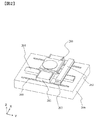
図2を参照して、本開示で提案するスタック型のXYステージおいて上軸固定子を下軸テーブルから分離したステージ構造(以下、モータ分離構造と呼ぶ)の構成例を説明する。本実施例にて説明するステージ装置は、駆動力を発生する移動機構として、固定子と移動子を含むリニアモータ機構を採用している。図2の例では、試料室底部206上に試料をX−Y方向に移動させるためのステージ機構が設置されている。なお、試料室は荷電粒子線装置の場合、真空チャンバであり、ステージ機構は真空チャンバ底面、或いは真空チャンバ底面上に配置された支持部材等の上に配置される。
With reference to FIG. 2, a configuration example of a stage structure (hereinafter referred to as a motor separation structure) in which the upper shaft stator is separated from the lower shaft table in the stack type XY stage proposed in the present disclosure will be described. The stage device described in this embodiment employs a linear motor mechanism including a stator and a mover as a moving mechanism that generates a driving force. In the example of FIG. 2, a stage mechanism for moving the sample in the XY directions is installed on the
半導体ウェハ等の試料を保持する上軸テーブル201(第1のテーブル)は、上軸テーブル201をX方向に案内するガイドレールが設けられた下軸テーブル203(第2のテーブル)に支持されている。下軸テーブル203は、ガイドレール205によって案内され、下軸モータ固定子204と図示しない下軸モータ可動子を含むリニアモータ(第2の移動機構)によってY方向に移動する。
The upper shaft table 201 (first table) holding a sample such as a semiconductor wafer is supported by a lower shaft table 203 (second table) provided with a guide rail for guiding the upper shaft table 201 in the X direction. There is. The lower shaft table 203 is guided by the
一般的なステージでは、上軸テーブル201を位置決めするリニアモータの固定子を下軸テーブル203に搭載するが、固定子がヨークの場合、下軸テーブル質量が増大し、下軸駆動時の発熱増加や制御性劣化の問題が生じる。これに対し、図2の構成では、質量の大きい上軸モータ固定子202を下軸テーブル203と分離し、下軸テーブル203を追従可能なように、ガイドレール205に対応したキャリッジと駆動要素と位置センサを設ける。これにより、下軸可動部の質量を大幅に低減し、制御性の向上および発熱の低減を行う。その結果、スループット向上および熱変形起因の視野ずれ抑制を実現する。
In a general stage, a stator of a linear motor for positioning the upper shaft table 201 is mounted on the lower shaft table 203. However, when the stator is a yoke, the lower shaft table mass increases and heat generation increases when driving the lower shaft. And the problem of controllability deterioration occurs. On the other hand, in the configuration of FIG. 2, the upper
また、上軸モータ固定子202を下軸テーブル203の駆動機構とは別の駆動機構で移動させるため、上軸モータ固定子202を大きくしても、下軸テーブル203の駆動機構への負担とはならない。その結果、上軸モータ固定子202の大型化が可能となる。固定子が大型化するとモータの推力定数が上がるため、その分、可動子に供給する電流量を下げることができ、電流を供給することによる発熱量を低下することが可能となる。テーブルに伝達する熱量の低下に基づく、テーブルの熱膨張を抑制することができ、荷電粒子ビームの照射位置精度を高い状態に維持することが可能となる。
Further, since the upper
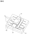
図3を参照して、本構成のステージの模式図を示す。上軸モータ固定子202を、上軸モータ可動子301を支持する下軸テーブル203に追従して移動させるために、上軸モータ固定子202を支持する移動体207を設け、当該移動体207を下軸テーブル203と共に移動させるための移動機構(第3の移動機構)を設ける。このように本実施例では、第1のテーブルを移動させるための第1の移動機構を構成する固定子と可動子をそれぞれ別の駆動機構によって移動させる。
With reference to FIG. 3, the schematic diagram of the stage of this structure is shown. In order to move the upper
第2の移動機構と第3の移動機構は、共通の固定子を用いる一方で、別の可動子を持つことになるが、リニアモータのヨークが形成する磁場とコイルの位置関係は、駆動方向と垂直な方向において、mmオーダの位置誤差が許容できるため、上軸モータ固定子202の下軸テーブル203に対する追従誤差は数100μmオーダ以下であれば制御性の劣化とならず実現が容易である。上軸モータ固定子202にかかる上軸テーブル201の駆動方向のモータ反力はガイドレール205により支持され位置決め誤差とならない。
The second moving mechanism and the third moving mechanism use a common stator while having another movable element, but the positional relationship between the magnetic field formed by the yoke of the linear motor and the coil is the driving direction. Since a position error on the order of mm can be tolerated in a direction perpendicular to, the following error with respect to the lower shaft table 203 of the upper
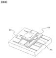
図4は上側モータ固定子202を支持する移動体207用に、モータ可動子402を設けたステージ構造を示す図である。本実施例では、下軸テーブル203を駆動するリニアモータを構成するモータ可動子401と、モータ可動子402は共通の固定子(下軸モータ固定子204)内を移動する構成となっている。また、テーブルや移動体の位置を特定するためのスケールを共用する構成となっている。上軸モータ固定子202の位置決めには、下軸テーブル203と下軸モータ固定子202と下軸用スケール405を共用しコスト増加を抑制することが可能である。
FIG. 4 is a diagram showing a stage structure in which a
下軸用スケールヘッド403で下軸テーブル203の位置を測定し、スケールヘッド404で上軸モータ固定子202の位置を測定する。スケール405は、二つのヘッド403および404で共用することが可能である。スケールヘッドはスケールの目盛や物理量等を読み込むことによって、テーブル等の位置を特定するためのものであり、その検出面はスケールに対向して配置される。
The position of the lower shaft table 203 is measured by the lower
下軸テーブル203は、モータ可動子401によって駆動される。上軸モータ固定子202は、モータ可動子402によって駆動される。モータ固定子204は、可動子401と402で共用することが可能である。
The lower shaft table 203 is driven by the
図5を参照して、上軸固定子を支持するガイドを別に設けた構成例を示す。上軸固定子を支持するガイドレール502を、下軸テーブル203を支持するガイドレール501と別に設けることで、上軸モータ固定子202を駆動するモータの熱がガイドレール501を介して本ステージに伝達するのを防ぐことが可能である。特に、低発熱化のために、上軸テーブル201のコイル電流を低下させる場合、最大推力を保つためには上軸固定子202を大型化して磁束密度を上げる必要がある。その場合、上軸固定子202の質量が増大して、固定子駆動側の発熱が増大する。その場合でも、ガイドを分離することで、ウェハへの伝熱を抑制することが可能となる。また、上軸固定子202の位置決め精度は、下軸テーブル203程の高精度は要求されないため、ガイドレール502を剛性の低い低摩擦なものに変更するなどの対応も可能である。また、ガイドレール502を低精度なものに変えてコストダウンを図っても、下軸テーブル203の位置決め精度が劣化することはない。
With reference to FIG. 5, a configuration example in which a guide for supporting the upper shaft stator is separately provided is shown. By providing the
図6を参照して、モータを2セット用いた構成例を示す。高推力に特化したモータ601および603に加え、高分解能に特化したモータ602および604を搭載する構成とした場合でも、下軸テーブル203の搭載物の質量がほとんど増大せず、高速化と高精度化の両立が可能である。
Referring to FIG. 6, a configuration example using two sets of motors is shown. Even when the
モータ固定子601および603は、低電流で大推力を出力可能なように磁束密度高く製作され推力定数が大きいものを採用する(第1の移動機構)。また、モータ固定子602および604は、電流ノイズに対する振動発生を抑制するため、磁束密度が低く推力定数が小さくなるよう製作されたものを採用する(第4の移動機構)。また、モータ固定子602および604は、SEM観察範囲内のみ駆動可能であればよいので、ストロークを短くすることでコストダウン可能である。
For the
図6に例示するような構成では、図4に例示したような第1の移動機構を構成するモータ可動子401、第3の移動機構を構成するモータ可動子402に加え、モータ602(固定子)を支持する移動体605を第1の移動機構や第3の移動機構に追従して移動させる第5の移動機構を構成するモータ可動子(図示せず)を設ける。図6の例では2つの移動体とテーブルが連動して移動する。
In the configuration illustrated in FIG. 6, in addition to the
二つのモータを用いる場合の運用方法として、ウェハ交換時やチップ間移動などの高速位置決め時は、大推力なモータ601および603を使用して、低電流で高速な位置決めを行い、モータ発熱を抑制する。SEM観察時は、低振動なモータ602および604を使用して、電流ノイズによる像揺れを抑制する。
As an operation method when using two motors, at the time of high-speed positioning such as wafer exchange or movement between chips, high-
図7を参照して、下軸テーブルおよび上軸固定子の位置決め制御系を示す。
本ステージの制御系のブロック図を示す。上軸固定子は、下軸テーブルの位置と常に一定の相対距離を保つよう独立制御される。
Referring to FIG. 7, a positioning control system for the lower shaft table and the upper shaft stator is shown.
The block diagram of the control system of this stage is shown. The upper shaft stator is independently controlled so as to always maintain a constant relative distance from the position of the lower shaft table.
下軸テーブル制御器701により、下軸テーブルプラント特性702が制御され、リニアスケール403および404などで読み取った下軸テーブルと上軸固定子の相対変位を上軸固定子駆動モータ制御器703の指令値として使用し、上軸固定子駆動モータプラント特性704の位置制御を行う。
なお、上軸テーブルの制御系は、一般的な制御系と同様でよい。
The lower-
The control system of the upper axis table may be the same as a general control system.
図8を参照して、ムービングマグネット化(MM化)した構成例を示す。この構成では、本ステージでモータ発熱が発生せず、ガイドの摩擦熱のみとなるため大幅なスループット向上が可能となる。また、コイルセレクタにより、電流を流すコイルを切り替えることで磁石と重ならないコイル部分からは電磁波が出ないようにし、像ノイズへの影響を防ぐことが可能である。 With reference to FIG. 8, a configuration example in which a moving magnet (MM) is used is shown. With this configuration, the motor does not generate heat in this stage, and only the frictional heat of the guide is used, so that it is possible to significantly improve the throughput. In addition, the coil selector can switch the coil through which the current is passed so that the electromagnetic wave is not emitted from the coil portion that does not overlap the magnet, and the influence on the image noise can be prevented.
また、下軸テーブル側に上軸モータヨーク802を取り付け、移動体側に上軸モータコイル801を取り付けることによって、テーブル側で発生する発熱量をほぼゼロにできるので、テーブルの熱膨張を抑制することが可能となる。下軸側の駆動機構も同様であり、下軸モータコイル803がテーブルと非接触に設置されているため、やはりテーブル側の発熱量を極小化することが可能となる。
Further, since the upper
また、ムービングマグネット化を行い、コイルセレクタを用いる場合、固定子であるコイルからは多数のケーブルを配線する必要がある。ステージ可動時にはケーブルの抵抗が位置決め誤差要因となるため、発熱抑制と位置決め精度向上がトレードオフとなる。しかし、上記構成のように固定子を分離することでケーブルの抵抗が本ステージの誤差とならないため、高精度化が可能である。 Further, when a moving magnet is used and a coil selector is used, it is necessary to wire a large number of cables from the coil which is the stator. Since the resistance of the cable becomes a positioning error factor when the stage is movable, heat generation suppression and positioning accuracy improvement are trade-offs. However, by separating the stator as in the above configuration, the resistance of the cable does not cause an error in the main stage, and therefore high accuracy can be achieved.
101 電子光学系鏡筒
104 レーザ干渉計
105 テーブル
106 ウェハ
107 ガイド
108 チャック
109 コントローラ
111 ミラー
112 試料室
113 除振マウント
201 上軸テーブル
202 上軸モータ固定子
203 下軸テーブル
204 下軸モータ固定子
205 ガイドレール
206 試料室底面
207 上軸固定子移動体
301 上軸モータ可動子
401 下軸テーブル駆動用モータ可動子
402 上軸モータ固定子駆動用モータ可動子
403 下軸用スケールヘッド
404 上軸モータ固定子位置測定用スケールヘッド
405 下軸用スケール
501 下軸テーブル用ガイドレール
502 上軸固定子用ガイドレール
601 上軸モータ固定子A(大推力)
602 上軸モータ固定子B(高分解能)
603 下軸モータ固定子A(大推力)
604 下軸モータ固定子B(高分解能)
701 下軸テーブル制御器
702 下軸テーブルプラント特性
703 上軸固定子駆動モータ制御器
704 上軸固定子駆動モータプラント特性
801 上軸モータコイル
802 上軸モータヨーク
803 下軸モータコイル
602 Upper shaft motor stator B (high resolution)
603 Lower shaft motor stator A (large thrust)
604 Lower shaft motor B (high resolution)
701 Lower
Claims (7)
前記第1の方向へ前記第1のテーブルを移動させる駆動力を発生する第1の移動機構と、前記第2の方向へ前記第2のテーブルを移動させる駆動力を発生する第2の移動機構と、前記第1の移動機構に含まれる固定子を支持する移動体と、当該移動体を前記第2のテーブルの前記第2の移動方向への移動に追従して移動させる第3の移動機構を備えたことを特徴とするステージ装置。 A stage that includes a first table that supports a sample and moves the sample in a first direction, and a second table that moves the first table in a second direction different from the first direction. A device,
A first moving mechanism that generates a driving force that moves the first table in the first direction, and a second moving mechanism that generates a driving force that moves the second table in the second direction. And a moving body that supports a stator included in the first moving mechanism, and a third moving mechanism that moves the moving body following the movement of the second table in the second moving direction. A stage device comprising:
前記第1の移動機構に含まれる可動子と、前記第3の移動機構に含まれる可動子は、共通の固定子内を移動することを特徴とするステージ装置。 In claim 1,
A stage device in which a mover included in the first moving mechanism and a mover included in the third moving mechanism move in a common stator.
前記第2の方向に沿って設置されるスケールと、前記第2のテーブルに前記スケールに対向するように設置される第1のスケールヘッドと、前記移動体に前記スケールに対向するように設置される第2のスケールヘッドを備えたことを特徴とするステージ装置。 In claim 1,
A scale installed along the second direction, a first scale head installed on the second table so as to face the scale, and installed at the moving body so as to face the scale. A stage device comprising a second scale head.
前記第2のテーブルを前記第2の方向に案内する第1のガイドレールと、前記移動体を前記第2の方向に案内する第2のガイドレールを備えたことを特徴とするステージ装置。 In claim 1,
A stage apparatus comprising: a first guide rail that guides the second table in the second direction, and a second guide rail that guides the moving body in the second direction.
前記第1の方向へ前記第1のテーブルを移動させる駆動力を発生する第4の移動機構と、当該第4の移動機構に含まれる固定子を支持する移動体と、当該移動体を前記第2のテーブルの前記第2の移動方向への移動に追従して移動させる第5の移動機構を備えたことを特徴とするステージ装置。 In claim 1,
A fourth moving mechanism that generates a driving force that moves the first table in the first direction, a moving body that supports a stator included in the fourth moving mechanism, and the moving body that is the first moving mechanism. A stage device comprising a fifth moving mechanism for moving the table of No. 2 following the movement of the table in the second moving direction.
前記第1の移動機構に含まれるモータと、前記第4の移動機構に含まれるモータは、推力定数が異なることを特徴とするステージ装置。 In claim 5,
Wherein the motor included in the first moving mechanism, the motor included in the prior SL fourth moving mechanism, a stage apparatus characterized by thrust constant is different.
前記第1の方向へ前記第1のテーブルを移動させる駆動力を発生する第1の移動機構と、前記第2の方向へ前記第2のテーブルを移動させる駆動力を発生する第2の移動機構と、前記第1の移動機構に含まれる固定子を支持する移動体と、当該移動体を前記第2のテーブルの前記第2の移動方向への移動に追従して移動させる第3の移動機構を備えたことを特徴とする荷電粒子線装置。 A charged particle beam column for irradiating a charged particle beam to a sample placed in a sample chamber, a first table that supports the sample and moves the sample in a first direction, and the first table. Charged particle beam device comprising a second table for moving the table in a second direction different from the first direction,
A first moving mechanism that generates a driving force that moves the first table in the first direction, and a second moving mechanism that generates a driving force that moves the second table in the second direction. And a moving body that supports a stator included in the first moving mechanism, and a third moving mechanism that moves the moving body following the movement of the second table in the second moving direction. A charged particle beam device comprising:
Priority Applications (3)
| Application Number | Priority Date | Filing Date | Title |
|---|---|---|---|
| JP2017034274A JP6735693B2 (en) | 2017-02-27 | 2017-02-27 | Stage device and charged particle beam device |
| US15/902,639 US10366912B2 (en) | 2017-02-27 | 2018-02-22 | Stage apparatus and charged particle beam apparatus |
| TW107105959A TWI667682B (en) | 2017-02-27 | 2018-02-22 | Platform device and charged particle beam device |
Applications Claiming Priority (1)
| Application Number | Priority Date | Filing Date | Title |
|---|---|---|---|
| JP2017034274A JP6735693B2 (en) | 2017-02-27 | 2017-02-27 | Stage device and charged particle beam device |
Publications (3)
| Publication Number | Publication Date |
|---|---|
| JP2018142405A JP2018142405A (en) | 2018-09-13 |
| JP2018142405A5 JP2018142405A5 (en) | 2019-08-22 |
| JP6735693B2 true JP6735693B2 (en) | 2020-08-05 |
Family
ID=63246502
Family Applications (1)
| Application Number | Title | Priority Date | Filing Date |
|---|---|---|---|
| JP2017034274A Active JP6735693B2 (en) | 2017-02-27 | 2017-02-27 | Stage device and charged particle beam device |
Country Status (3)
| Country | Link |
|---|---|
| US (1) | US10366912B2 (en) |
| JP (1) | JP6735693B2 (en) |
| TW (1) | TWI667682B (en) |
Families Citing this family (2)
| Publication number | Priority date | Publication date | Assignee | Title |
|---|---|---|---|---|
| US10600614B2 (en) * | 2017-09-29 | 2020-03-24 | Hitachi High-Technologies Corporation | Stage device and charged particle beam device |
| JP7114450B2 (en) * | 2018-12-04 | 2022-08-08 | 株式会社日立ハイテク | Stage device and charged particle beam device |
Family Cites Families (10)
| Publication number | Priority date | Publication date | Assignee | Title |
|---|---|---|---|---|
| JP2003045785A (en) | 2001-08-01 | 2003-02-14 | Nikon Corp | Stage apparatus, aligner, and device-manufacturing method |
| JP2004172557A (en) * | 2002-11-22 | 2004-06-17 | Canon Inc | Stage apparatus and its control method |
| JP4362862B2 (en) * | 2003-04-01 | 2009-11-11 | 株式会社ニコン | Stage apparatus and exposure apparatus |
| JP2004356222A (en) * | 2003-05-27 | 2004-12-16 | Canon Inc | Stage equipment, its control method, aligner and device manufacturing method |
| JP4655039B2 (en) * | 2004-06-07 | 2011-03-23 | 株式会社ニコン | Stage apparatus, exposure apparatus, and exposure method |
| US7557529B2 (en) | 2005-01-11 | 2009-07-07 | Nikon Corporation | Stage unit and exposure apparatus |
| US8355114B2 (en) | 2009-06-19 | 2013-01-15 | Nikon Corporation | Exposure apparatus and device manufacturing method |
| WO2012032768A1 (en) * | 2010-09-07 | 2012-03-15 | 株式会社ニコン | Mobile apparatus, exposure apparatus, exposure method, method for manufacturing flat-panel display, and method for manufacturing device |
| US8988655B2 (en) | 2010-09-07 | 2015-03-24 | Nikon Corporation | Exposure apparatus, movable body apparatus, flat-panel display manufacturing method, and device manufacturing method |
| US10802407B2 (en) * | 2015-09-30 | 2020-10-13 | Nikon Corporation | Exposure apparatus, exposure method, manufacturing method of flat-panel display, and device manufacturing method |
-
2017
- 2017-02-27 JP JP2017034274A patent/JP6735693B2/en active Active
-
2018
- 2018-02-22 TW TW107105959A patent/TWI667682B/en active
- 2018-02-22 US US15/902,639 patent/US10366912B2/en active Active
Also Published As
| Publication number | Publication date |
|---|---|
| JP2018142405A (en) | 2018-09-13 |
| US20180247855A1 (en) | 2018-08-30 |
| TW201842525A (en) | 2018-12-01 |
| TWI667682B (en) | 2019-08-01 |
| US10366912B2 (en) | 2019-07-30 |
Similar Documents
| Publication | Publication Date | Title |
|---|---|---|
| US6949844B2 (en) | High-speed precision positioning apparatus | |
| US6359677B2 (en) | Stage apparatus, exposure apparatus using the same, and a device manufacturing method | |
| US7365456B2 (en) | Positioning apparatus and charged-particle-beam exposure apparatus | |
| KR20000012083A (en) | Stage system and stage driving method for use in exposure apparatus | |
| JPH0577126A (en) | Movable stage device and driving method thereof | |
| US8823309B2 (en) | Stage device | |
| JP6735693B2 (en) | Stage device and charged particle beam device | |
| US7915768B2 (en) | Linear guide with an integrated linear motor | |
| WO2019225110A1 (en) | Stage device, charged particle beam device, and vacuum device | |
| WO2011108170A1 (en) | Stage device | |
| JP7189847B2 (en) | Magnetic levitation stage device and charged particle beam device or vacuum device using it | |
| KR20220024572A (en) | 6 Degrees of Freedom Workpiece Stage | |
| JP5140103B2 (en) | Linear motor pair, moving stage, and electron microscope | |
| JP6214946B2 (en) | Active brake, sample stage with active brake, and charged particle beam device | |
| JP2007184193A (en) | Charged particle beam device | |
| JP2015230927A (en) | Mobile device and charged particle beam drawing device | |
| JP2015230926A (en) | Mobile device and charged particle beam drawing device | |
| JP2022093882A (en) | Magnetic levitation plane stage device, vacuum device, and charged particle beam device | |
| WO2022264287A1 (en) | Stage device, charged particle beam device, and vacuum device | |
| JP3797670B2 (en) | Static pressure stage and scanning exposure apparatus | |
| JP5090392B2 (en) | Stage equipment | |
| WO2023042589A1 (en) | Stage device, charged particle beam device, and vacuum device | |
| US20230343622A1 (en) | Stage apparatus, charged particle beam apparatus, and optical inspection apparatus | |
| JP2005301936A (en) | Xy stage | |
| JP2008131762A (en) | Controller and aligner |
Legal Events
| Date | Code | Title | Description |
|---|---|---|---|
| A521 | Request for written amendment filed |
Free format text: JAPANESE INTERMEDIATE CODE: A523 Effective date: 20170301 |
|
| RD02 | Notification of acceptance of power of attorney |
Free format text: JAPANESE INTERMEDIATE CODE: A7422 Effective date: 20180731 |
|
| RD04 | Notification of resignation of power of attorney |
Free format text: JAPANESE INTERMEDIATE CODE: A7424 Effective date: 20180803 |
|
| A521 | Request for written amendment filed |
Free format text: JAPANESE INTERMEDIATE CODE: A523 Effective date: 20190708 |
|
| A621 | Written request for application examination |
Free format text: JAPANESE INTERMEDIATE CODE: A621 Effective date: 20190708 |
|
| A977 | Report on retrieval |
Free format text: JAPANESE INTERMEDIATE CODE: A971007 Effective date: 20200630 |
|
| TRDD | Decision of grant or rejection written | ||
| A01 | Written decision to grant a patent or to grant a registration (utility model) |
Free format text: JAPANESE INTERMEDIATE CODE: A01 Effective date: 20200707 |
|
| A61 | First payment of annual fees (during grant procedure) |
Free format text: JAPANESE INTERMEDIATE CODE: A61 Effective date: 20200714 |
|
| R150 | Certificate of patent or registration of utility model |
Ref document number: 6735693 Country of ref document: JP Free format text: JAPANESE INTERMEDIATE CODE: R150 |