JP6735239B2 - Hermetic compressor and refrigeration cycle device - Google Patents

Hermetic compressor and refrigeration cycle device Download PDF

Info

Publication number
JP6735239B2
JP6735239B2 JP2017010326A JP2017010326A JP6735239B2 JP 6735239 B2 JP6735239 B2 JP 6735239B2 JP 2017010326 A JP2017010326 A JP 2017010326A JP 2017010326 A JP2017010326 A JP 2017010326A JP 6735239 B2 JP6735239 B2 JP 6735239B2
Authority
JP
Japan
Prior art keywords
plate
inner diameter
iron core
hermetic compressor
rotor
Prior art date
Legal status (The legal status is an assumption and is not a legal conclusion. Google has not performed a legal analysis and makes no representation as to the accuracy of the status listed.)
Active
Application number
JP2017010326A
Other languages
Japanese (ja)
Other versions
JP2018119437A (en
Inventor
裕太郎 杉山
裕太郎 杉山
鈴木 秀明
秀明 鈴木
武士 知念
武士 知念
史弥 安西
史弥 安西
Current Assignee (The listed assignees may be inaccurate. Google has not performed a legal analysis and makes no representation or warranty as to the accuracy of the list.)
Carrier Japan Corp
Original Assignee
Toshiba Carrier Corp
Priority date (The priority date is an assumption and is not a legal conclusion. Google has not performed a legal analysis and makes no representation as to the accuracy of the date listed.)
Filing date
Publication date
Application filed by Toshiba Carrier Corp filed Critical Toshiba Carrier Corp
Priority to JP2017010326A priority Critical patent/JP6735239B2/en
Priority to CN201711170050.4A priority patent/CN108343609B/en
Publication of JP2018119437A publication Critical patent/JP2018119437A/en
Application granted granted Critical
Publication of JP6735239B2 publication Critical patent/JP6735239B2/en
Active legal-status Critical Current
Anticipated expiration legal-status Critical

Links

Images

Classifications

    • FMECHANICAL ENGINEERING; LIGHTING; HEATING; WEAPONS; BLASTING
    • F04POSITIVE - DISPLACEMENT MACHINES FOR LIQUIDS; PUMPS FOR LIQUIDS OR ELASTIC FLUIDS
    • F04CROTARY-PISTON, OR OSCILLATING-PISTON, POSITIVE-DISPLACEMENT MACHINES FOR LIQUIDS; ROTARY-PISTON, OR OSCILLATING-PISTON, POSITIVE-DISPLACEMENT PUMPS
    • F04C23/00Combinations of two or more pumps, each being of rotary-piston or oscillating-piston type, specially adapted for elastic fluids; Pumping installations specially adapted for elastic fluids; Multi-stage pumps specially adapted for elastic fluids
    • F04C23/02Pumps characterised by combination with, or adaptation to, specific driving engines or motors
    • FMECHANICAL ENGINEERING; LIGHTING; HEATING; WEAPONS; BLASTING
    • F04POSITIVE - DISPLACEMENT MACHINES FOR LIQUIDS; PUMPS FOR LIQUIDS OR ELASTIC FLUIDS
    • F04CROTARY-PISTON, OR OSCILLATING-PISTON, POSITIVE-DISPLACEMENT MACHINES FOR LIQUIDS; ROTARY-PISTON, OR OSCILLATING-PISTON, POSITIVE-DISPLACEMENT PUMPS
    • F04C29/00Component parts, details or accessories of pumps or pumping installations, not provided for in groups F04C18/00 - F04C28/00
    • F04C29/02Lubrication; Lubricant separation
    • F04C29/026Lubricant separation
    • FMECHANICAL ENGINEERING; LIGHTING; HEATING; WEAPONS; BLASTING
    • F04POSITIVE - DISPLACEMENT MACHINES FOR LIQUIDS; PUMPS FOR LIQUIDS OR ELASTIC FLUIDS
    • F04CROTARY-PISTON, OR OSCILLATING-PISTON, POSITIVE-DISPLACEMENT MACHINES FOR LIQUIDS; ROTARY-PISTON, OR OSCILLATING-PISTON, POSITIVE-DISPLACEMENT PUMPS
    • F04C29/00Component parts, details or accessories of pumps or pumping installations, not provided for in groups F04C18/00 - F04C28/00
    • F04C29/04Heating; Cooling; Heat insulation
    • F04C29/045Heating; Cooling; Heat insulation of the electric motor in hermetic pumps

Landscapes

  • Engineering & Computer Science (AREA)
  • Mechanical Engineering (AREA)
  • General Engineering & Computer Science (AREA)
  • Compressor (AREA)
  • Applications Or Details Of Rotary Compressors (AREA)

Description

本発明に係る実施形態は、密閉型圧縮機、および冷凍サイクル装置に関する。 Embodiments according to the present invention relate to a hermetic compressor and a refrigeration cycle device.

密閉ケーシングと、密閉ケーシングに収容される圧縮機構と、密閉ケーシングに収容され、圧縮機構を駆動する電動機と、密閉ケーシングの電動機側に設けられ、圧縮されたガス冷媒を吐出する吐出管と、電動機の回転子の吐出管側に取り付けられた油分離部材と、を備える密閉型圧縮機が知られている。 A hermetic casing, a compression mechanism housed in the hermetic casing, an electric motor housed in the hermetic casing and driving the compression mechanism, a discharge pipe provided on the electric motor side of the hermetic casing for discharging a compressed gas refrigerant, and an electric motor. There is known a hermetic compressor including an oil separating member attached to the discharge pipe side of the rotor.

電動機の回転子は、圧縮機構側から吐出管側へ圧縮されたガス冷媒を導く冷媒通路を有している。 The rotor of the electric motor has a refrigerant passage that guides the compressed gas refrigerant from the compression mechanism side to the discharge pipe side.

特開平8−177738号公報JP-A-8-177738

従来の密閉型圧縮機は、回転子の吐出管側の端面に開口する冷媒通路から圧縮されたガス冷媒を流出させる。この冷媒通路は、回転子の圧縮機構側の端面から吐出管側の端面に至る。ガス冷媒に混入している潤滑油は、この冷媒通路を通過した後に油分離部材によって分離されるが、冷媒通路を通過するガス冷媒による回転子の冷却効果は小さい。 A conventional hermetic compressor discharges a compressed gas refrigerant from a refrigerant passage opened at an end surface of a rotor on a discharge pipe side. The refrigerant passage extends from the end surface on the compression mechanism side of the rotor to the end surface on the discharge pipe side. The lubricating oil mixed in the gas refrigerant is separated by the oil separation member after passing through the refrigerant passage, but the cooling effect of the rotor by the gas refrigerant passing through the refrigerant passage is small.

そこで、本発明は、電動機の回転子内を通過するガス冷媒により、回転子をより効率良く冷却可能な密閉型圧縮機と、この密閉型圧縮機を備える冷凍サイクル装置を提案する。 Therefore, the present invention proposes a hermetic compressor that can cool the rotor more efficiently with a gas refrigerant passing through the rotor of the electric motor, and a refrigeration cycle apparatus including the hermetic compressor.

前記の課題を解決するため本発明の実施形態に係る密閉型圧縮機は、密閉ケースと、前記密閉ケース内に設けられる圧縮機構と、前記密閉ケース内に設けられる電動機と、
前記電動機の回転駆動力を前記圧縮機構へ伝達する回転軸と、前記圧縮機構によって圧縮され前記密閉ケース内に吐出されるガス冷媒に混入している潤滑油を分離する油分離部と、を備え、前記電動機の回転子は、前記回転軸に固定される小内径を有する小内径鉄心部と、前記小内径鉄心部よりも径の大きな内径を有し、前記回転軸の端部側に空間を形成する大内径鉄心部と、前記小内径鉄心部を軸方向に貫き前記空間に繋がる第一冷媒通路と、を有する鉄心と、前記大内径鉄心部側の端部に前記回転子に対する前記油分離部の自転を阻止する第一板と、前記回転軸の中心線方向において前記回転子からの前記油分離部の離脱を阻止する第二板と、を備え、前記油分離部は、前記空間に入り込む基部を有し、前記第一板および前記第二板には、前記空間に繋がる第二冷媒通路が設けられている。
A hermetic compressor according to an embodiment of the present invention to solve the above problems, a hermetic case, a compression mechanism provided in the hermetic case, an electric motor provided in the hermetic case,
A rotary shaft that transmits the rotational driving force of the electric motor to the compression mechanism; and an oil separation unit that separates the lubricating oil that is mixed by the gas refrigerant that is compressed by the compression mechanism and discharged into the closed case. The rotor of the electric motor has a small inner diameter iron core portion having a small inner diameter fixed to the rotating shaft, and an inner diameter larger than the small inner diameter iron core portion, and a space is provided on the end side of the rotating shaft. An iron core having a large inner diameter core portion to be formed and a first refrigerant passage that axially penetrates the small inner diameter iron core portion and is connected to the space, and the oil separation for the rotor at the end portion on the large inner diameter iron core portion side. A first plate for preventing rotation of the portion, and a second plate for preventing separation of the oil separating portion from the rotor in the direction of the center line of the rotating shaft , wherein the oil separating portion is provided in the space. have a base entering, wherein the first plate and the second plate, a second refrigerant passage leading to the space that is provided.

また、本発明の実施形態に係る冷凍サイクル装置は、前記密閉型圧縮機と、放熱器と、膨張装置と、吸熱器と、前記密閉型圧縮機と前記放熱器と前記膨張装置と前記吸熱器とを接続して冷媒を流通させる冷媒管と、を備えている。 Further, a refrigeration cycle apparatus according to an embodiment of the present invention includes the hermetic compressor, a radiator, an expansion device, a heat absorber, the hermetic compressor, the radiator, the expansion device, and the heat absorber. And a refrigerant pipe for connecting the and to circulate the refrigerant.

本発明の実施形態に係る冷凍サイクル装置の概略的な図。The schematic diagram of the refrigerating cycle device concerning the embodiment of the present invention. 本発明の実施形態に係る密閉型圧縮機の回転子および油分離部の軸方向断面図。The axial sectional view of the rotor and the oil separation part of the hermetic compressor according to the embodiment of the present invention. 本発明の実施形態に係る密閉型圧縮機の小内径鉄心部を構成する板材の平面図。The top view of the board material which comprises the small inner diameter iron core part of the hermetic type compressor which concerns on embodiment of this invention. 本発明の実施形態に係る密閉型圧縮機の大内径鉄心部を構成する板材の平面図。The top view of the board material which comprises the large inner diameter iron core part of the hermetic type compressor which concerns on embodiment of this invention. 本発明の実施形態に係る密閉型圧縮機の第二板の平面図。The top view of the 2nd board of the hermetic type compressor concerning the embodiment of the present invention. 本発明の実施形態に係る密閉型圧縮機の第一板の平面図。1 is a plan view of a first plate of a hermetic compressor according to an embodiment of the present invention. 本発明の実施形態に係る密閉型圧縮機のバランサーを構成する板材の平面図。The top view of the board material which constitutes the balancer of the closed type compressor concerning the embodiment of the present invention. 本発明の実施形態に係る密閉型圧縮機の回転子および油分離部の他の例の軸方向断面図。FIG. 6 is an axial cross-sectional view of another example of the rotor and the oil separation unit of the hermetic compressor according to the embodiment of the present invention.

本発明に係る密閉型圧縮機、および冷凍サイクル装置の実施形態について、図1から図8を参照して説明する。 Embodiments of a hermetic compressor and a refrigeration cycle device according to the present invention will be described with reference to FIGS. 1 to 8.

図1は、本発明の実施形態に係る冷凍サイクル装置の概略的な図である。 FIG. 1 is a schematic diagram of a refrigeration cycle apparatus according to an embodiment of the present invention.

図1に示すように、本実施形態に係る冷凍サイクル装置1は、密閉型圧縮機2と、放熱器である凝縮器3と、膨張装置5と、吸熱器である蒸発器6と、アキュームレータ7と、冷媒管8と、を備えている。冷媒管8は、密閉型圧縮機2と凝縮器3と膨張装置5と蒸発器6とアキュームレータ7とを順次に接続して冷媒を流通させる。 As shown in FIG. 1, a refrigeration cycle apparatus 1 according to this embodiment includes a hermetic compressor 2, a condenser 3 that is a radiator, an expansion device 5, an evaporator 6 that is a heat absorber, and an accumulator 7. And a refrigerant pipe 8. The refrigerant pipe 8 sequentially connects the hermetic compressor 2, the condenser 3, the expansion device 5, the evaporator 6, and the accumulator 7 to allow the refrigerant to flow.

本実施形態に係る密閉型圧縮機2は、密閉ケース11と、密閉ケース11内の上部に設けられる電動機12と、密閉ケース11内の下部に設けられる圧縮機構部13と、電動機12の回転駆動力を圧縮機構部13へ伝達する回転軸14と、回転軸14を回転自在に支持する主軸受15と、主軸受15と協働して回転軸14を回転自在に支持する副軸受16と、圧縮機構部13によって圧縮され密閉ケース11内に吐出されるガス冷媒に混じっている潤滑油を分離する油分離部17と、を備えている。 The hermetic compressor 2 according to the present embodiment includes a hermetic case 11, an electric motor 12 provided in an upper part of the hermetic case 11, a compression mechanism portion 13 provided in a lower part of the hermetic case 11, and a rotational drive of the electric motor 12. A rotary shaft 14 that transmits a force to the compression mechanism portion 13, a main bearing 15 that rotatably supports the rotary shaft 14, and a sub bearing 16 that cooperates with the main bearing 15 to rotatably support the rotary shaft 14. An oil separation unit 17 that separates the lubricating oil mixed with the gas refrigerant that is compressed by the compression mechanism unit 13 and is discharged into the closed case 11.

密閉ケース11は、円筒形である。密閉ケース11は、上下に設けられた半球形の鏡板と、円筒形の胴部と、を備えている。密閉ケース11の胴部には、冷媒を密閉型圧縮機2へ導く吸込管8bが接続されている。吸込管8bは、アキュームレータ7に繋がれている。吸込管8bは、冷媒管8の一部である。密閉ケース11の上側の鏡板には、冷媒を密閉型圧縮機2から吐出させる吐出管8aが接続されている。吐出管8aは、冷媒管8に繋がれている。 The closed case 11 has a cylindrical shape. The closed case 11 includes a hemispherical end plate that is provided above and below, and a cylindrical body. A suction pipe 8 b that guides the refrigerant to the hermetic compressor 2 is connected to the body of the hermetic case 11. The suction pipe 8b is connected to the accumulator 7. The suction pipe 8b is a part of the refrigerant pipe 8. A discharge pipe 8 a for discharging the refrigerant from the hermetic compressor 2 is connected to the upper end plate of the hermetic case 11. The discharge pipe 8a is connected to the refrigerant pipe 8.

電動機12は、圧縮機構部13を回転駆動させる駆動力を発生させる。電動機12は密閉ケース11の内壁に固定される固定子18と、固定子18に周囲を囲まれて回転軸14に設けられる回転子19と、を備えている。 The electric motor 12 generates a driving force that rotationally drives the compression mechanism unit 13. The electric motor 12 includes a stator 18 fixed to the inner wall of the closed case 11, and a rotor 19 surrounded by the stator 18 and provided on the rotating shaft 14.

回転子19の上面、つまり、密閉ケース11の上側の鏡板を臨む面には、油分離部17が設けられている。 An oil separator 17 is provided on the upper surface of the rotor 19, that is, on the surface of the closed case 11 that faces the upper end plate.

回転軸14は、電動機12と圧縮機構部13とを互いに連結している。回転軸14は、電動機12が発生させる駆動力を圧縮機構部13へ伝達する。 The rotating shaft 14 connects the electric motor 12 and the compression mechanism portion 13 to each other. The rotating shaft 14 transmits the driving force generated by the electric motor 12 to the compression mechanism unit 13.

回転軸14の中間部分14aは、主軸受15に回転自在に支持されている。回転軸14の下端部分14bは、副軸受16に回転自在に支持されている。主軸受15および副軸受16は、圧縮機構部13の一部でもあって、圧縮機構部13を上下から挟んでいる。つまり、回転軸14は、圧縮機構部13を貫通している。 The intermediate portion 14 a of the rotary shaft 14 is rotatably supported by the main bearing 15. The lower end portion 14b of the rotary shaft 14 is rotatably supported by the sub bearing 16. The main bearing 15 and the sub bearing 16 are also a part of the compression mechanism portion 13, and sandwich the compression mechanism portion 13 from above and below. That is, the rotary shaft 14 penetrates the compression mechanism portion 13.

また、回転軸14は、主軸受15に支持されている中間部分14aと副軸受16に支持されている下端部分14bとの間に、複数の偏心部21、21を備えている。複数の偏心部21のうち、主軸受15に近い側を第一偏心部22と呼び、副軸受16に近い側を第二偏心部23と呼ぶ。それぞれの偏心部21、21は、回転軸14の中心に不一致の中心を有する円盤、あるいは円柱である。それぞれの偏心部21、21の中心は、回転軸14のまわりに約180度の位相差で偏心されている。第一偏心部22は、電動機12に近い上側に配置され、第二偏心部23は、電動機12から遠い下側に配置されている。 Further, the rotary shaft 14 is provided with a plurality of eccentric portions 21, 21 between an intermediate portion 14 a supported by the main bearing 15 and a lower end portion 14 b supported by the auxiliary bearing 16. Of the plurality of eccentric parts 21, the side closer to the main bearing 15 is called the first eccentric part 22, and the side closer to the sub bearing 16 is called the second eccentric part 23. Each of the eccentric parts 21 and 21 is a disk or a cylinder having a center that does not coincide with the center of the rotating shaft 14. The centers of the respective eccentric parts 21, 21 are eccentric about the rotation shaft 14 with a phase difference of about 180 degrees. The first eccentric portion 22 is arranged on the upper side close to the electric motor 12, and the second eccentric portion 23 is arranged on the lower side far from the electric motor 12.

圧縮機構部13は、電動機12が回転軸14を回転駆動することによって、ガス状の冷媒を吸込んで圧縮し、かつ吐出する。圧縮機構部13は、密閉ケース11に収容されていて、密閉ケース11の下部に配置されている。密閉ケース11の下部は潤滑油(図示省略)で満たされていて、圧縮機構部13の大部分は、この潤滑油に浸されている。 The compression mechanism portion 13 sucks and compresses a gaseous refrigerant and discharges it by the electric motor 12 drivingly rotating the rotating shaft 14. The compression mechanism portion 13 is housed in the closed case 11, and is arranged below the closed case 11. The lower portion of the closed case 11 is filled with lubricating oil (not shown), and most of the compression mechanism portion 13 is immersed in this lubricating oil.

圧縮機構部13は、複数の圧縮機構25、25を備えている。つまり、圧縮機構部13は、密閉ケース11内に設けられる第一圧縮機構26と、密閉ケース11内に設けられる第二圧縮機構27と、第一圧縮機構26と第二圧縮機構27との間に設けられる仕切板29と、を備えている。 The compression mechanism section 13 includes a plurality of compression mechanisms 25, 25. That is, the compression mechanism unit 13 includes the first compression mechanism 26 provided in the closed case 11, the second compression mechanism 27 provided in the closed case 11, and the first compression mechanism 26 and the second compression mechanism 27. And a partition plate 29 provided in the.

第一圧縮機構26は、円形の第一シリンダ室31を有する第一シリンダ32と、第一シリンダ室31内に配置される環状の第一ローラ33と、を備えている。 The first compression mechanism 26 includes a first cylinder 32 having a circular first cylinder chamber 31, and an annular first roller 33 arranged in the first cylinder chamber 31.

第二圧縮機構27は、円形の第二シリンダ室41を有する第二シリンダ42と、第二シリンダ室41内に配置される環状の第二ローラ43と、を備えている。 The second compression mechanism 27 includes a second cylinder 42 having a circular second cylinder chamber 41, and an annular second roller 43 arranged in the second cylinder chamber 41.

第一シリンダ32および第二シリンダ42は、回転軸14の軸方向に積み重なるように配置されている。上側の第一シリンダ32は、電動機12に近い側に配置されている。 The first cylinder 32 and the second cylinder 42 are arranged so as to be stacked in the axial direction of the rotary shaft 14. The upper first cylinder 32 is arranged on the side closer to the electric motor 12.

第一シリンダ32は、複数箇所の溶接部51によって密閉ケース11に固定されている。溶接部51は、第一シリンダ32を密閉ケース11に固定するスポット溶接によって形成されている。 The first cylinder 32 is fixed to the closed case 11 by a plurality of welded portions 51. The welded portion 51 is formed by spot welding that fixes the first cylinder 32 to the closed case 11.

第一シリンダ室31および第二シリンダ室41の中心は、実質的に回転軸14の回転中心に重なっている。これらシリンダ室31、41は、実質的に同じ直径寸法と同じ高さ寸法(回転軸14方向の寸法)を有している。第一シリンダ室31は、第一シリンダ32の内側の空間であって、主軸受15および仕切板29によって閉鎖されている。第一シリンダ室31内には、回転軸14の第一偏心部22が配置されている。第二シリンダ室41は、第二シリンダ42の内側の空間であって仕切板29と副軸受16によって閉鎖されている。第二シリンダ室41内には、回転軸14の第二偏心部23が配置されている。 The centers of the first cylinder chamber 31 and the second cylinder chamber 41 substantially overlap with the center of rotation of the rotary shaft 14. The cylinder chambers 31 and 41 have substantially the same diameter dimension and the same height dimension (dimension in the direction of the rotating shaft 14). The first cylinder chamber 31 is a space inside the first cylinder 32 and is closed by the main bearing 15 and the partition plate 29. The first eccentric portion 22 of the rotating shaft 14 is arranged in the first cylinder chamber 31. The second cylinder chamber 41 is a space inside the second cylinder 42 and is closed by the partition plate 29 and the auxiliary bearing 16. The second eccentric portion 23 of the rotary shaft 14 is arranged in the second cylinder chamber 41.

上側の主軸受15は、ボルトなどの締結部材52によって第一シリンダ32に固定されている。上側の主軸受15には、第一シリンダ室31内で圧縮された冷媒を吐出する吐出ポートと吐出弁とを有する第一吐出弁機構(図示省略)と、第一吐出マフラ55とが設けられている。第一吐出マフラ55は、吐出孔(図示省略)を有している。第一吐出マフラ55は、第一吐出弁機構に覆い被さっている。第一吐出弁機構の吐出ポートは、第一シリンダ室31に繋がれており、圧縮機構部13の圧縮作用にともない第一シリンダ室31内が所定圧値に達したときに吐出弁が吐出ポートを開放して、圧縮された冷媒を第一吐出マフラ55内に吐出する。 The upper main bearing 15 is fixed to the first cylinder 32 by a fastening member 52 such as a bolt. The upper main bearing 15 is provided with a first discharge valve mechanism (not shown) having a discharge port and a discharge valve for discharging the refrigerant compressed in the first cylinder chamber 31, and a first discharge muffler 55. ing. The first discharge muffler 55 has a discharge hole (not shown). The first discharge muffler 55 covers the first discharge valve mechanism. The discharge port of the first discharge valve mechanism is connected to the first cylinder chamber 31, and when the inside of the first cylinder chamber 31 reaches a predetermined pressure value due to the compression action of the compression mechanism unit 13, the discharge valve is the discharge port. To discharge the compressed refrigerant into the first discharge muffler 55.

下側の副軸受16は、ボルトなどの締結部材53によって第一シリンダ32に固定されている。締結部材53は、第二シリンダ42と仕切板29を貫いて第一シリンダ32に達している。下側の副軸受16には、第二シリンダ室41内で圧縮された冷媒を吐出する吐出ポートと吐出弁とを有する第二吐出弁機構(図示省略)と、第二吐出マフラ56とが設けられている。第二吐出マフラ56は、第二吐出弁機構に覆い被さっている。第二吐出弁機構の吐出ポートは、第二シリンダ室41に接続されており、圧縮機構部13の圧縮作用にともない第二シリンダ室41内が所定圧値に達したときに吐出弁が吐出ポートを開放して、圧縮された冷媒を第二吐出マフラ56内に吐出する。 The lower auxiliary bearing 16 is fixed to the first cylinder 32 by a fastening member 53 such as a bolt. The fastening member 53 reaches the first cylinder 32 through the second cylinder 42 and the partition plate 29. The lower auxiliary bearing 16 is provided with a second discharge valve mechanism (not shown) having a discharge port and a discharge valve for discharging the refrigerant compressed in the second cylinder chamber 41, and a second discharge muffler 56. Has been. The second discharge muffler 56 covers the second discharge valve mechanism. The discharge port of the second discharge valve mechanism is connected to the second cylinder chamber 41, and when the inside of the second cylinder chamber 41 reaches a predetermined pressure value due to the compression action of the compression mechanism unit 13, the discharge valve is the discharge port. To release the compressed refrigerant into the second discharge muffler 56.

第一ローラ33は、第一偏心部22の周面に嵌合されて第一シリンダ室31内に収容されている。第一ローラ33は、回転軸14の回転にともなって、外周面の一部を第一シリンダ室31の内周面に沿って線接触させながら偏心運動する。 The first roller 33 is fitted in the peripheral surface of the first eccentric portion 22 and is housed in the first cylinder chamber 31. With the rotation of the rotary shaft 14, the first roller 33 eccentrically moves while part of the outer peripheral surface is in line contact with the inner peripheral surface of the first cylinder chamber 31.

第二ローラ43は、第二偏心部23の周面に嵌合されて第二シリンダ室41内に収容されている。第二ローラ43は、回転軸14の回転にともなって、外周面の一部を第二シリンダ室41の内周面に沿って線接触させながら偏心運動する。 The second roller 43 is fitted into the peripheral surface of the second eccentric portion 23 and is housed in the second cylinder chamber 41. With the rotation of the rotating shaft 14, the second roller 43 eccentrically moves while a part of the outer peripheral surface is in line contact with the inner peripheral surface of the second cylinder chamber 41.

なお、第一ローラ33と第一シリンダ32との接触、および第二ローラ43と第二シリンダ42との接触は、直接的な接触ではなく、油膜(図示省略)を介在させた間接的なものであるが、説明の便宜のために、これら油膜を介した接触を単に「接触」と表現する。第一ローラ33と第一偏心部22との間、第二ローラ43と第二偏心部23との間、第一ローラ33と主軸受15との間、第二ローラ43と副軸受16との間、第一ローラ33と仕切板29との間、第二ローラ43と仕切板29との間も同じである。 The contact between the first roller 33 and the first cylinder 32 and the contact between the second roller 43 and the second cylinder 42 are not direct contact but indirect with an oil film (not shown) interposed. However, for convenience of description, the contact through the oil film is simply expressed as “contact”. Between the first roller 33 and the first eccentric portion 22, between the second roller 43 and the second eccentric portion 23, between the first roller 33 and the main bearing 15, and between the second roller 43 and the sub bearing 16. The same applies to the space between the first roller 33 and the partition plate 29, and the space between the second roller 43 and the partition plate 29.

第一シリンダ32には、第一スライドベーン57が設けられている。第一スライドベーン57は、第一シリンダ32の高さ方向へ拡がる板状であり、第一コイルスプリング59により先端を第一ローラ33の外周面に押されている。第一圧縮機構26は、第一ローラ33と第一スライドベーン57とで区画される圧縮室の容積を第一ローラ33の回転にともなって変化させ、冷媒を圧縮する。 The first cylinder 32 is provided with a first slide vane 57. The first slide vane 57 has a plate shape that expands in the height direction of the first cylinder 32, and its tip is pressed by the first coil spring 59 against the outer peripheral surface of the first roller 33. The first compression mechanism 26 changes the volume of the compression chamber defined by the first roller 33 and the first slide vane 57 with the rotation of the first roller 33, and compresses the refrigerant.

第二シリンダ42には、第二スライドベーン67が設けられている。第二スライドベーン67は、第二シリンダ42の高さ方向へ拡がる板状であり、第二コイルスプリング69により、先端を第二ローラ43の外周面に押されている。第二圧縮機構27は、第二ローラ43と第二ベーン68とで区画される圧縮室の容積を第二ローラ43の回転にともなって変化させ、冷媒を圧縮する。 The second cylinder 42 is provided with a second slide vane 67. The second slide vane 67 has a plate shape that extends in the height direction of the second cylinder 42, and the tip end thereof is pressed against the outer peripheral surface of the second roller 43 by the second coil spring 69. The second compression mechanism 27 compresses the refrigerant by changing the volume of the compression chamber defined by the second roller 43 and the second vane 68 with the rotation of the second roller 43.

吸込管8bは、第一シリンダ32に接続される第一吸込管71と、第二シリンダ42に接続される第二吸込管72と、を含んでいる。第一吸込管71および第二吸込管72は、それぞれ個別にアキュームレータ7から密閉ケース11へ達している。第一吸込管71は、上下方向に延びる円筒形のアキュームレータ7の下部鏡板から下方へ突出し、水平方向へ緩やかに曲がって延びている。そして、第一吸込管71は、水平に延びて密閉ケース11を貫き、第一シリンダ32に接続されている。第二吸込管72は、アキュームレータ7の下部鏡板から下方へ突出し、水平方向へ緩やかに曲がって延びている。そして、第二吸込管72は、水平に延びて密閉ケース11を貫き、第二シリンダ42に接続されている。 The suction pipe 8b includes a first suction pipe 71 connected to the first cylinder 32 and a second suction pipe 72 connected to the second cylinder 42. The first suction pipe 71 and the second suction pipe 72 individually reach the sealed case 11 from the accumulator 7. The first suction pipe 71 projects downward from the lower end plate of the cylindrical accumulator 7 that extends in the vertical direction, and extends by gently bending in the horizontal direction. The first suction pipe 71 extends horizontally, penetrates the closed case 11, and is connected to the first cylinder 32. The second suction pipe 72 projects downward from the lower end plate of the accumulator 7 and extends by gently bending in the horizontal direction. The second suction pipe 72 extends horizontally, penetrates the closed case 11, and is connected to the second cylinder 42.

次いで、電動機12の回転子19および油分離部17について詳細に説明する。 Next, the rotor 19 and the oil separator 17 of the electric motor 12 will be described in detail.

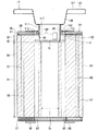
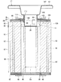
図2は、本発明の実施形態に係る密閉型圧縮機の回転子および油分離部の軸方向断面図である。 FIG. 2 is an axial cross-sectional view of the rotor and the oil separation unit of the hermetic compressor according to the embodiment of the present invention.

図1および図2に示すように、本実施形態に係る密閉型圧縮機2の電動機12の回転子19は、小内径を有する小内径鉄心部81および小内径鉄心部81の内径より大きい内径を有する大内径鉄心部82を有する鉄心83と、鉄心83の大内径鉄心部82の端部側に設けられ、回転子19に対する油分離部17の自転を阻止する第一板85と、第一板85の鉄心83とは反対側に設けられ、回転軸14の中心線方向において回転子19からの油分離部17の離脱を阻止する第二板86と、バランサー87と、回転子19を一体化する複数の鋲88、88を備えている。 As shown in FIGS. 1 and 2, the rotor 19 of the electric motor 12 of the hermetic compressor 2 according to the present embodiment has a small inner diameter core portion 81 having a small inner diameter and an inner diameter larger than the inner diameters of the small inner diameter core portion 81. An iron core 83 having a large inner diameter iron core portion 82, a first plate 85 which is provided on an end side of the large inner diameter iron core portion 82 of the iron core 83 and which prevents rotation of the oil separating portion 17 with respect to the rotor 19, and a first plate. The second plate 86, which is provided on the side opposite to the iron core 83 of 85, for preventing the oil separating portion 17 from separating from the rotor 19 in the direction of the center line of the rotating shaft 14, the balancer 87, and the rotor 19 are integrated. A plurality of tacks 88, 88 are provided.

鉄心83は、板材91、92の積層体である。換言すると、小内径鉄心部81および大内径鉄心部82は、板材91、92の積層体である。小内径鉄心部81および大内径鉄心部82は、互いに異なる形状の板材91、92の積層体である。 The iron core 83 is a laminated body of plate materials 91 and 92. In other words, the small inner diameter iron core portion 81 and the large inner diameter iron core portion 82 are a laminated body of the plate materials 91 and 92. The small-inner-diameter iron core portion 81 and the large-inner-diameter iron core portion 82 are laminated bodies of plate materials 91 and 92 having different shapes.

鉄心83は、小内径鉄心部81を軸方向に貫く第一冷媒通路95を有している。つまり、第一冷媒通路95は、小内径鉄心部81を構成する複数の板材91に設けられている。第一冷媒通路95は、鉄心83の回転中心線に対して平行に延びている。 The iron core 83 has a first refrigerant passage 95 penetrating the small inner diameter iron core portion 81 in the axial direction. That is, the first refrigerant passage 95 is provided in the plurality of plate members 91 forming the small inner diameter iron core portion 81. The first refrigerant passage 95 extends parallel to the rotation center line of the iron core 83.

また、鉄心83は、その全長に渡って磁石挿入孔96を有している。つまり、磁石挿入孔96は、小内径鉄心部81を構成する複数の板材91、および大内径鉄心部82を構成する板材92の両方に設けられている。磁石挿入孔96は、鉄心83の回転中心線に対して平行に延びている。磁石挿入孔96には永久磁石97が埋設されている。 Further, the iron core 83 has a magnet insertion hole 96 over its entire length. That is, the magnet insertion holes 96 are provided in both the plurality of plate members 91 that form the small inner diameter iron core portion 81 and the plate members 92 that form the large inner diameter iron core portion 82. The magnet insertion hole 96 extends parallel to the rotation center line of the iron core 83. A permanent magnet 97 is embedded in the magnet insertion hole 96.

小内径鉄心部81の外径寸法と大内径鉄心部82の外径寸法とは、実質的に同じである。換言すると、鉄心83の外径寸法は、実質的に一様である。鉄心83の外周面は、固定子18の内周面に対面している。 The outer diameter dimension of the small inner diameter core portion 81 and the outer diameter dimension of the large inner diameter core portion 82 are substantially the same. In other words, the outer diameter dimension of the iron core 83 is substantially uniform. The outer peripheral surface of the iron core 83 faces the inner peripheral surface of the stator 18.

小内径鉄心部81は、回転軸14に固定される小内径Dsを有している。小内径鉄心部81の内周面は、回転軸14に固定されている。回転子19は、小内径鉄心部81によって回転軸14に固定されている。 The small inner diameter core portion 81 has a small inner diameter Ds fixed to the rotating shaft 14. The inner peripheral surface of the small inner diameter core portion 81 is fixed to the rotating shaft 14. The rotor 19 is fixed to the rotating shaft 14 by a small inner diameter iron core portion 81.

大内径鉄心部82は、小内径Dsよりも大径な大内径Dlを有している。大内径鉄心部82は、回転軸14の上端部側に空間Sを形成している。大内径鉄心部82は、隣接する小内径鉄心部81を介して回転軸14に固定されている。 The large inner diameter core portion 82 has a large inner diameter Dl which is larger than the small inner diameter Ds. The large inner diameter core portion 82 forms a space S on the upper end side of the rotating shaft 14. The large inner diameter iron core portion 82 is fixed to the rotating shaft 14 via the adjacent small inner diameter iron core portions 81.

第一冷媒通路95は、大内径鉄心部82が区画する空間Sに繋がっている。つまり、第一冷媒通路95を通って油分離部17へ向かうガス冷媒は、空間Sを通過する。 The first refrigerant passage 95 is connected to the space S defined by the large inner diameter iron core portion 82. That is, the gas refrigerant flowing toward the oil separation portion 17 through the first refrigerant passage 95 passes through the space S.

第一板85は、油分離部17のいわゆる回り止めである。第二板86は、油分離部17のいわゆる抜け止めである。第一板85の外径寸法および第二板86の外径寸法は、小内径鉄心部81の外径寸法(=大内径鉄心部82の外径寸法)以下に設定される。 The first plate 85 is a so-called detent for the oil separating section 17. The second plate 86 is a so-called retaining stopper of the oil separating section 17. The outer diameter dimension of the first plate 85 and the second plate 86 are set to be equal to or less than the outer diameter dimension of the small inner diameter core portion 81 (=the outer diameter dimension of the large inner diameter core portion 82).

バランサー87、87は、板材98の積層体である。バランサー87、87は、鉄心83の両端面に設けられている。 The balancers 87, 87 are laminated bodies of plate materials 98. The balancers 87, 87 are provided on both end surfaces of the iron core 83.

鋲88、88は、小内径鉄心部81を構成する複数の板材91、大内径鉄心部82を構成する複数の板材92、第一板85、第二板86、およびバランサー87を構成する板材98を貫通し、これらを一体化する。 The tacks 88, 88 are a plurality of plate members 91 that form the small inner diameter core portion 81, a plurality of plate members 92 that form the large inner diameter core portion 82, a first plate 85, a second plate 86, and a plate member 98 that forms the balancer 87. Through and integrate them.

また、回転子19は、第一板85および第二板86を貫いて空間Sに繋がる第二冷媒通路99を備えている。 Further, the rotor 19 includes a second refrigerant passage 99 that penetrates the first plate 85 and the second plate 86 and is connected to the space S.

第二冷媒通路99は、空間Sから回転子19の外へガス冷媒を流出させる。第二冷媒通路99から流出したガス冷媒は、油分離部17によって油を分離される。 The second refrigerant passage 99 allows the gas refrigerant to flow out of the space S to the outside of the rotor 19. The gas refrigerant flowing out from the second refrigerant passage 99 is separated into oil by the oil separation unit 17.

油分離部17は、油分離ディスク101と、保持力発生環102と、を備えている。 The oil separation unit 17 includes an oil separation disk 101 and a holding force generation ring 102.

油分離ディスク101は、板金加工、例えばプレス加工や絞り加工による金属製の板材の一体成形品である。油分離部17は、第一板85および第二板86を貫いて空間Sに入り込む筒形の基部105と、回転子19から遠ざかるほど拡がる円錐台形のコーン部106と、回転中心線に直交する方向へ拡がる環形の鍔部107と、を備えている。 The oil separation disk 101 is an integrally molded product of a metal plate material that is formed by sheet metal processing, such as pressing or drawing. The oil separator 17 is orthogonal to the center of rotation, and a cylindrical base 105 that penetrates the first plate 85 and the second plate 86 and enters the space S, a truncated cone cone 106 that spreads away from the rotor 19. And a ring-shaped collar portion 107 that expands in the direction.

基部105の外径は、小内径Dsよりも大きい。基部105は、基部105の周壁の一部を径方向外側へ切り起こした爪108、108を有している。爪108、108は、基部105の周方向へ複数、例えば3つ設けられている。爪108、108は、空間Sから基部105が抜け出そうとすると第二板86に引っ掛かり、これを阻止する。他方、空間Sへ基部105を挿入する際、爪108、108は、これを妨げない。 The outer diameter of the base 105 is larger than the small inner diameter Ds. The base portion 105 has pawls 108 and 108 in which a part of the peripheral wall of the base portion 105 is cut and raised outward in the radial direction. A plurality of, for example, three claws 108, 108 are provided in the circumferential direction of the base 105. The claws 108, 108 are caught on the second plate 86 when the base 105 is about to come out from the space S, and prevent this. On the other hand, when inserting the base 105 into the space S, the claws 108, 108 do not interfere with this.

保持力発生環102は、弾性に富む鋼などの金属材料の一体成形品である。保持力発生環102は、油分離ディスク101の基部105が嵌め込まれるリング部111と、放射状に延びる複数の脚部112と、を備えている。複数の脚部112は、板ばねであり、リング部111を回転子19の表面から浮いた状態に支持できるよう、勾配を有している。複数の脚部112は、油分離ディスク101の基部105を回転子19の空間Sから引く抜く方向へばね力を発生させる。この脚部112のばね力は、基部105の爪108を第二板86に強く押し当て、油分離ディスク101と回転子19の連結を強固にする。 The holding force generating ring 102 is an integrally molded product of a metal material such as steel having a high elasticity. The holding force generating ring 102 includes a ring portion 111 into which the base portion 105 of the oil separation disk 101 is fitted and a plurality of radially extending leg portions 112. The plurality of leg portions 112 are leaf springs and have a slope so that the ring portion 111 can be supported in a state of floating above the surface of the rotor 19. The plurality of legs 112 generate a spring force in the direction of pulling out the base 105 of the oil separation disk 101 from the space S of the rotor 19. The spring force of the leg portion 112 strongly presses the claw 108 of the base portion 105 against the second plate 86 to strengthen the connection between the oil separation disk 101 and the rotor 19.

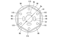
図3は、本発明の実施形態に係る密閉型圧縮機の小内径鉄心部を構成する板材の平面図である。 FIG. 3 is a plan view of a plate material forming the small inner diameter core portion of the hermetic compressor according to the embodiment of the present invention.

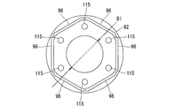
図4は、本発明の実施形態に係る密閉型圧縮機の大内径鉄心部を構成する板材の平面図である。 FIG. 4 is a plan view of a plate material forming the large-inner-diameter iron core portion of the hermetic compressor according to the embodiment of the present invention.

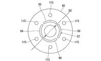
図5は、本発明の実施形態に係る密閉型圧縮機の第二板の平面図である。 FIG. 5 is a plan view of the second plate of the hermetic compressor according to the embodiment of the present invention.

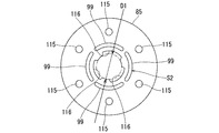
図6は、本発明の実施形態に係る密閉型圧縮機の第一板の平面図である。 FIG. 6 is a plan view of the first plate of the hermetic compressor according to the embodiment of the present invention.

図7は、本発明の実施形態に係る密閉型圧縮機のバランサーを構成する板材の平面図である。 FIG. 7: is a top view of the board|plate material which comprises the balancer of the hermetic type compressor which concerns on embodiment of this invention.

図2および図3に示すように、本実施形態に係る密閉型圧縮機2の小内径鉄心部81を構成する板材91は、小内径Dsを有する環形の板材である。 As shown in FIGS. 2 and 3, the plate material 91 that constitutes the small inner diameter core portion 81 of the hermetic compressor 2 according to the present embodiment is an annular plate material having a small inner diameter Ds.

第一冷媒通路95は、板材91の内周、つまり小内径Dsの周囲に配置されている。第一冷媒通路95は、複数、例えば4つあり、小内径Dsの周囲に等間隔に配置されている。 The first refrigerant passage 95 is arranged on the inner circumference of the plate member 91, that is, around the small inner diameter Ds. There are a plurality of, for example, four first refrigerant passages 95, which are arranged at equal intervals around the small inner diameter Ds.

磁石挿入孔96は、板材91の外周近傍に配置されている。磁石挿入孔96は、径方向に直交する方向へ直線的に延びるスリット形を有する。磁石挿入孔96は、複数、例えば6つあり、全体で正六角形状に配置されている。 The magnet insertion hole 96 is arranged near the outer periphery of the plate material 91. The magnet insertion hole 96 has a slit shape linearly extending in a direction orthogonal to the radial direction. There are a plurality of, for example, six magnet insertion holes 96, and they are arranged in a regular hexagonal shape as a whole.

鋲88が挿し通される鋲挿入孔115は、第一冷媒通路95よりも外側、かつ磁石挿入孔96よりも内側であって、磁石挿入孔96の近傍に配置されている。鋲挿入孔115は、複数、例えば6つあり、等間隔に配置されている。 The tack insertion hole 115 through which the tack 88 is inserted is arranged outside the first refrigerant passage 95 and inside the magnet insertion hole 96 and in the vicinity of the magnet insertion hole 96. There are a plurality of, for example, six tack insertion holes 115, and they are arranged at equal intervals.

図2および図4に示すように、本実施形態に係る密閉型圧縮機2の大内径鉄心部82を構成する板材92は、大内径Dlを有する環形の板材である。大内径Dlは、板材91の第一冷媒通路95の最外周寸法よりも大きい。 As shown in FIGS. 2 and 4, the plate member 92 that constitutes the large inner diameter core portion 82 of the hermetic compressor 2 according to the present embodiment is a ring-shaped plate member having a large inner diameter Dl. The large inner diameter Dl is larger than the outermost peripheral dimension of the first refrigerant passage 95 of the plate member 91.

板材92は、第一冷媒通路95を有していない一方、板材91と同じ箇所に磁石挿入孔96、および鋲挿入孔115を有している。 The plate member 92 does not have the first refrigerant passage 95, but has a magnet insertion hole 96 and a tack insertion hole 115 at the same position as the plate member 91.

図2および図5に示すように、本実施形態に係る密閉型圧縮機2の第二板86は、油分離部17の基部105を挿入可能な内径D2を有する環形の板材である。内径D2は、基部105の外径よりも若干大きく、かつ、基部105の爪108に引っ掛かる。 As shown in FIGS. 2 and 5, the second plate 86 of the hermetic compressor 2 according to the present embodiment is a ring-shaped plate member having an inner diameter D2 into which the base 105 of the oil separation unit 17 can be inserted. The inner diameter D2 is slightly larger than the outer diameter of the base 105 and is caught by the claw 108 of the base 105.

第二冷媒通路99は、第二板86の内周、つまり内径D2の周囲に配置されている。第二冷媒通路99は、複数、例えば4つあり、内径D2の周囲に等間隔に配置されている。第二冷媒通路99の最外周寸法は、大内径鉄心部82の大内径Dl以下である。4つの第二冷媒通路99の合計断面積S2は、4つの第一冷媒通路95の合計断面積S1よりも小さい。 The second refrigerant passage 99 is arranged on the inner circumference of the second plate 86, that is, around the inner diameter D2. There are a plurality of, for example, four second refrigerant passages 99, which are arranged at equal intervals around the inner diameter D2. The outermost peripheral dimension of the second refrigerant passage 99 is equal to or smaller than the large inner diameter Dl of the large inner diameter core portion 82. The total sectional area S2 of the four second refrigerant passages 99 is smaller than the total sectional area S1 of the four first refrigerant passages 95.

第二板86は、板材91と同じ箇所に鋲挿入孔115を有している。 The second plate 86 has a tack insertion hole 115 at the same position as the plate member 91.

図2および図6に示すように、本実施形態に係る密閉型圧縮機2の第一板85は、油分離部17の基部105を挿入可能な内径D1を有する環形の板材である。内径D1は第二板86の内径D2と実質的に同じであることが好ましい。 As shown in FIGS. 2 and 6, the first plate 85 of the hermetic compressor 2 according to the present embodiment is a ring-shaped plate member having an inner diameter D1 into which the base 105 of the oil separating unit 17 can be inserted. The inner diameter D1 is preferably substantially the same as the inner diameter D2 of the second plate 86.

第一板85の内周は、複数の凹部116を有している。凹部116は、第二板86の内径D2を通過した油分離ディスク101の爪108が中立状態で配置される(逃げる)空間である。凹部116に納まった爪108は、回転子19に対する油分離ディスク101の自転を規制する。この凹部116と、第二板86の内径D2との寸法差は、第一板85と第二板86との間に段部117(図2)を生じさせる。この段部117に爪108が引っ掛かることによって、油分離ディスク101は、回転軸14の中心線方向において、回転子19からの離脱が阻止される。 The inner periphery of the first plate 85 has a plurality of recesses 116. The concave portion 116 is a space in which the claw 108 of the oil separation disk 101 that has passed through the inner diameter D2 of the second plate 86 is arranged (escape) in a neutral state. The claw 108 housed in the recess 116 restricts the rotation of the oil separation disk 101 with respect to the rotor 19. The dimensional difference between the recess 116 and the inner diameter D2 of the second plate 86 causes a step 117 (FIG. 2) between the first plate 85 and the second plate 86. When the claw 108 is caught by the step 117, the oil separation disk 101 is prevented from being separated from the rotor 19 in the direction of the center line of the rotating shaft 14.

第二板86は、第二板86と同じ箇所に第二冷媒通路99および鋲挿入孔115を有している。 The second plate 86 has the second refrigerant passage 99 and the tack insertion hole 115 at the same position as the second plate 86.

図2および図7に示すように、本実施形態に係る密閉型圧縮機2のバランサー87を構成する板材98は、油分離部17の基部105を挿入可能な内径を有する環形の板材である。板材98の内径は、大内径鉄心部82の大内径Dlと実質的に同じであることが好ましい。 As shown in FIGS. 2 and 7, the plate member 98 that constitutes the balancer 87 of the hermetic compressor 2 according to this embodiment is a ring-shaped plate member having an inner diameter into which the base 105 of the oil separation unit 17 can be inserted. The inner diameter of the plate material 98 is preferably substantially the same as the large inner diameter Dl of the large inner diameter core portion 82.

板材98は、回転子19および圧縮機構部13の回転バランスを調整するための重量軽減孔118を有している。 The plate member 98 has a weight reducing hole 118 for adjusting the rotational balance of the rotor 19 and the compression mechanism section 13.

板材98は、第二板86と同じ箇所に鋲挿入孔115を有している。 The plate material 98 has a tack insertion hole 115 at the same position as the second plate 86.

本実施形態に係る密閉型圧縮機2において、第二圧縮機構27で圧縮されたガス冷媒は、第二吐出弁機構の吐出ポートから吐出された後、副軸受16、第二シリンダ42、仕切板29、第一シリンダ32、主軸受15に設けられる冷媒通路(図示省略)を通過し、第一吐出マフラ55を通って密閉ケース11内に吐出される。第一シリンダ32で圧縮されたガス冷媒は、第一吐出弁機構の吐出ポートから吐出された後、第一吐出マフラ55で第二圧縮機構27で圧縮されたガス冷媒に合流し、第一吐出マフラ55を通って密閉ケース11内に吐出される。密閉ケース11内に吐出されたガス冷媒は、固定子18と回転子19との隙間や、固定子18の巻き線(図示省略)の隙間や、回転子19の冷媒通路(第一冷媒通路95、空間S、第二冷媒通路99)を通り、油分離ディスク101が取り付けられている側に導かれる。ガス冷媒は、油分離ディスク101に当たって、ガス冷媒に混ざっている潤滑油が分離される。潤滑油の分離された冷媒ガスは、吐出管8aから吐出され冷凍サイクル装置1に供給される。 In the hermetic compressor 2 according to the present embodiment, the gas refrigerant compressed by the second compression mechanism 27 is discharged from the discharge port of the second discharge valve mechanism, and then the sub bearing 16, the second cylinder 42, the partition plate. 29, the first cylinder 32, and a refrigerant passage (not shown) provided in the main bearing 15, and is discharged into the closed case 11 through the first discharge muffler 55. The gas refrigerant compressed by the first cylinder 32 is discharged from the discharge port of the first discharge valve mechanism, and then merges with the gas refrigerant compressed by the second compression mechanism 27 by the first discharge muffler 55 to make the first discharge. It is discharged into the closed case 11 through the muffler 55. The gas refrigerant discharged into the closed case 11 has a gap between the stator 18 and the rotor 19, a gap between windings of the stator 18 (not shown), a refrigerant passage of the rotor 19 (first refrigerant passage 95). , The space S, the second refrigerant passage 99), and is guided to the side to which the oil separation disk 101 is attached. The gas refrigerant hits the oil separation disk 101, and the lubricating oil mixed with the gas refrigerant is separated. The refrigerant gas from which the lubricating oil has been separated is discharged from the discharge pipe 8a and supplied to the refrigeration cycle apparatus 1.

このとき、ガス冷媒は、回転子19の冷媒通路(第一冷媒通路95、空間S、第二冷媒通路99)を通る過程で回転子19を冷却する。特に空間Sにおいて、ガス冷媒は、回転子19から流出する前に、油分離ディスク101の基部105に触れる。油分離ディスク101は、鍔部107等からの放熱により、基部105の温度は空間S内のガス冷媒の温度よりも低い。そのため、ガス冷媒は油分離ディスク101の基部105に触れることにより冷却される。油分離ディスク101の基部105に触れて冷却された冷媒は、回転子19から流出する前に、回転子19をさらに冷却する。 At this time, the gas refrigerant cools the rotor 19 while passing through the refrigerant passages (the first refrigerant passage 95, the space S, the second refrigerant passage 99) of the rotor 19. Particularly in the space S, the gas refrigerant contacts the base portion 105 of the oil separation disk 101 before flowing out from the rotor 19. In the oil separation disk 101, the temperature of the base 105 is lower than the temperature of the gas refrigerant in the space S due to the heat radiation from the flange 107 and the like. Therefore, the gas refrigerant is cooled by touching the base 105 of the oil separation disk 101. The coolant cooled by touching the base portion 105 of the oil separation disk 101 further cools the rotor 19 before flowing out from the rotor 19.

また、回転子19から流出するガス冷媒は、(第二冷媒通路99の合計断面積S2)<(第一冷媒通路95の合計断面積S1)の関係から、空間Sから第二冷媒通路99を通って油分離ディスク101の鍔部107へ向かって吐出される際、流速が大きくなり、油分離ディスク101に衝突しやすくなり、油分離性能を向上させる。 Further, the gas refrigerant flowing out from the rotor 19 moves from the space S to the second refrigerant passage 99 from the relationship of (total sectional area S2 of the second refrigerant passage 99)<(total sectional area S1 of the first refrigerant passage 95). When discharged toward the flange 107 of the oil separation disc 101, the flow velocity increases, and the oil separation disc 101 is more likely to collide with the oil separation disc 101 to improve the oil separation performance.

図8は、本発明の実施形態に係る密閉型圧縮機の回転子および油分離部の他の例の軸方向断面図である。 FIG. 8 is an axial cross-sectional view of another example of the rotor and the oil separation unit of the hermetic compressor according to the embodiment of the present invention.

図8に示すように、本実施形態に係る密閉型圧縮機2の回転子19Aは、第二板86と鉄心83との間に複数の第一板85を備えている。 As shown in FIG. 8, the rotor 19A of the hermetic compressor 2 according to the present embodiment includes a plurality of first plates 85 between the second plate 86 and the iron core 83.

第二板86に隣接する第一板85は、油分離部17の回り止めとして機能している。 The first plate 85 adjacent to the second plate 86 functions as a detent for the oil separating section 17.

その他の第一板85は、油分離ディスク101が倒れ込む範囲(倒れ角)を規制する。第二板86から離れた第一板85は、油分離ディスク101が倒れ込むと、基部105に接触し、油分離ディスク101の倒れ込みを阻止して倒れ角を規制する。 The other first plate 85 regulates the range (tilt angle) in which the oil separation disk 101 falls. When the oil separation disc 101 falls down, the first plate 85 separated from the second plate 86 comes into contact with the base portion 105, prevents the oil separation disc 101 from falling down, and regulates the tilting angle.

本実施形態に係る密閉型圧縮機2および冷凍サイクル装置1は、回転軸14に固定される小内径Dsを有する小内径鉄心部81、小内径Dsよりも大径な大内径Dlを有し、回転軸14の端部側に空間Sを区画する大内径鉄心部82、および小内径鉄心部81を軸方向に貫き空間Sに繋がる第一冷媒通路95を有する鉄心83と、第一板85および第二板86を貫いて空間Sに入り込む基部105を有する油分離部17と、を備えている。そのため、密閉型圧縮機2および冷凍サイクル装置1は、回転子19から流出する以前に回転子19を冷却するガス冷媒をさらに冷却し、回転子19をより冷却できる。回転子19をより冷却することは、永久磁石97の減磁を防ぎ、密閉型圧縮機2の信頼性を向上させる。 The hermetic compressor 2 and the refrigeration cycle apparatus 1 according to the present embodiment have a small inner diameter core portion 81 having a small inner diameter Ds fixed to the rotating shaft 14, and a large inner diameter Dl larger than the small inner diameter Ds, An iron core 83 having a large inner diameter core portion 82 that divides the space S on the end side of the rotating shaft 14 and a first refrigerant passage 95 that penetrates the small inner diameter core portion 81 in the axial direction and is connected to the space S; a first plate 85; And an oil separation portion 17 having a base portion 105 that penetrates the second plate 86 and enters the space S. Therefore, the hermetic compressor 2 and the refrigeration cycle apparatus 1 can further cool the gas refrigerant that cools the rotor 19 before flowing out from the rotor 19, and further cool the rotor 19. Cooling the rotor 19 more effectively prevents demagnetization of the permanent magnet 97 and improves the reliability of the hermetic compressor 2.

また、大内径鉄心部82の空間Sは、回転子19の重心を圧縮機構部13側へ偏倚させる。そのため、回転軸14の振れ回りが抑制される。 In addition, the space S of the large-inner-diameter iron core portion 82 biases the center of gravity of the rotor 19 toward the compression mechanism portion 13 side. Therefore, whirling of the rotary shaft 14 is suppressed.

また、本実施形態に係る密閉型圧縮機2および冷凍サイクル装置1は、第一冷媒通路95の断面積S1よりも小さい断面積S2の第二冷媒通路99を備えている。そのため、密閉型圧縮機2および冷凍サイクル装置1は、回転子19から流出するガス冷媒の流速を高め、油分離性能を向上させる。 Further, the hermetic compressor 2 and the refrigeration cycle device 1 according to the present embodiment include the second refrigerant passage 99 having a sectional area S2 smaller than the sectional area S1 of the first refrigerant passage 95. Therefore, the hermetic compressor 2 and the refrigeration cycle device 1 increase the flow velocity of the gas refrigerant flowing out from the rotor 19 and improve the oil separation performance.

さらに、本実施形態に係る密閉型圧縮機2および冷凍サイクル装置1は、小内径鉄心部81の小内径Dsよりも大きい外径を有する基部105を備えている。そのため、密閉型圧縮機2および冷凍サイクル装置1は、空間Sにおいてガス冷媒に接する油分離ディスク101の表面積をより大きく確保することができる。空間Sにおいてガス冷媒に接する油分離ディスク101の表面積がより大きく確保されることによって、空間S内のガス冷媒は、より冷却され、回転子19をより低温に冷却する。 Further, the hermetic compressor 2 and the refrigeration cycle device 1 according to the present embodiment include the base 105 having an outer diameter larger than the small inner diameter Ds of the small inner diameter core 81. Therefore, the hermetic compressor 2 and the refrigeration cycle apparatus 1 can secure a larger surface area of the oil separation disk 101 in contact with the gas refrigerant in the space S. By ensuring a larger surface area of the oil separation disk 101 in contact with the gas refrigerant in the space S, the gas refrigerant in the space S is further cooled, and the rotor 19 is cooled to a lower temperature.

さらにまた、本実施形態に係る密閉型圧縮機2および冷凍サイクル装置1は、板材91、92を積層した鉄心83を備えている。そのため、密閉型圧縮機2および冷凍サイクル装置1は、鉄心83の小内径鉄心部81および大内径鉄心部82を容易に形成できる。 Furthermore, the hermetic compressor 2 and the refrigeration cycle apparatus 1 according to this embodiment include an iron core 83 in which plate materials 91 and 92 are laminated. Therefore, in the hermetic compressor 2 and the refrigeration cycle device 1, the small inner diameter core portion 81 and the large inner diameter iron core portion 82 of the iron core 83 can be easily formed.

したがって、本実施形態の密閉型圧縮機2および、密閉型圧縮機2を備える冷凍サイクル装置1によれば、回転子19内の冷媒通路を通過する前にガス冷媒を冷却し、回転子19をより効率良く冷却できる。 Therefore, according to the hermetic compressor 2 of the present embodiment and the refrigeration cycle apparatus 1 including the hermetic compressor 2, the gas refrigerant is cooled before passing through the refrigerant passage in the rotor 19, and the rotor 19 is cooled. Can be cooled more efficiently.

本発明のいくつかの実施形態を説明したが、これらの実施形態は、例として提示したものであり、発明の範囲を限定することは意図していない。これら新規な実施形態は、その他の様々な形態で実施されることが可能であり、発明の要旨を逸脱しない範囲で、種々の省略、置き換え、変更を行うことができる。これら実施形態やその変形は、発明の範囲や要旨に含まれるとともに、特許請求の範囲に記載された発明とその均等の範囲に含まれる。 Although some embodiments of the present invention have been described, these embodiments are presented as examples and are not intended to limit the scope of the invention. These novel embodiments can be implemented in various other forms, and various omissions, replacements, and changes can be made without departing from the spirit of the invention. These embodiments and their modifications are included in the scope and gist of the invention, and are also included in the invention described in the claims and the scope of equivalents thereof.

1…冷凍サイクル装置、2…密閉型圧縮機、3…放熱器、5…膨張装置、6…蒸発器、7…アキュームレータ、8…冷媒管、8a…吐出管、8b…吸込管、11…密閉ケース、12…電動機、13…圧縮機構部、14…回転軸、14a…中間部分、14b…下端部分、15…主軸受、16…副軸受、17…油分離部、18…固定子、19、19A…回転子、21…偏心部、22…第一偏心部、23…第二偏心部、25…圧縮機構、26…第一圧縮機構、27…第二圧縮機構、29…仕切板、31…第一シリンダ室、32…第一シリンダ、33…第一ローラ、41…第二シリンダ室、42…第二シリンダ、43…第二ローラ、51…溶接部、52…締結部材、53…締結部材、55…第一吐出マフラ、56…第二吐出マフラ、57…第一スライドベーン、59…第一コイルスプリング、67…第二スライドベーン、69…第二コイルスプリング、71…第一吸込管、72…第二吸込管、81…小内径鉄心部、82…大内径鉄心部、83…鉄心、85…第一板、86…第二板、87…バランサー、88…鋲、91、92…板材、95…第一冷媒通路、96…磁石挿入孔、97…永久磁石、98…板材、99…第二冷媒通路、101…油分離ディスク、102…保持力発生環、105…基部、106…コーン部、107…鍔部、108…爪、111…リング部、112…脚部、115…鋲挿入孔、116…凹部、117…段部、118…重量軽減孔。 DESCRIPTION OF SYMBOLS 1... Refrigeration cycle device, 2... Hermetic compressor, 3... Radiator, 5... Expansion device, 6... Evaporator, 7... Accumulator, 8... Refrigerant pipe, 8a... Discharge pipe, 8b... Suction pipe, 11... Sealed Case, 12... Electric motor, 13... Compression mechanism part, 14... Rotation shaft, 14a... Intermediate part, 14b... Lower end part, 15... Main bearing, 16... Sub bearing, 17... Oil separation part, 18... Stator, 19, 19A... Rotor, 21... Eccentric part, 22... First eccentric part, 23... Second eccentric part, 25... Compression mechanism, 26... First compression mechanism, 27... Second compression mechanism, 29... Partition plate, 31... 1st cylinder chamber, 32... 1st cylinder, 33... 1st roller, 41... 2nd cylinder chamber, 42... 2nd cylinder, 43... 2nd roller, 51... Welding part, 52... Fastening member, 53... Fastening member , 55... First discharge muffler, 56... Second discharge muffler, 57... First slide vane, 59... First coil spring, 67... Second slide vane, 69... Second coil spring, 71... First suction pipe, 72...Second suction pipe, 81...Small inner diameter iron core part, 82...Large inner diameter iron core part, 83...Iron core, 85...First plate, 86...Second plate, 87...Balancer, 88...Tacks, 91,92...Sheet material , 95... First refrigerant passage, 96... Magnet insertion hole, 97... Permanent magnet, 98... Plate material, 99... Second refrigerant passage, 101... Oil separation disk, 102... Holding force generating ring, 105... Base portion, 106... Cone Numerals, 107... Collar section, 108... Claw, 111... Ring section, 112... Leg section, 115... Tack insertion hole, 116... Recessed section, 117... Step section, 118... Weight reduction hole.

Claims (6)

密閉ケースと、
前記密閉ケース内に設けられる圧縮機構と、
前記密閉ケース内に設けられる電動機と、
前記電動機の回転駆動力を前記圧縮機構へ伝達する回転軸と、
前記圧縮機構によって圧縮され前記密閉ケース内に吐出されるガス冷媒に混入している潤滑油を分離する油分離部と、を備え、
前記電動機の回転子は、
前記回転軸に固定される小内径を有する小内径鉄心部と、前記小内径鉄心部よりも径の大きな内径を有し、前記回転軸の端部側に空間を形成する大内径鉄心部と、前記小内径鉄心部を軸方向に貫き前記空間に繋がる第一冷媒通路と、を有する鉄心と、
前記大内径鉄心部側の端部に前記回転子に対する前記油分離部の自転を阻止する第一板と、
前記回転軸の中心線方向において前記回転子からの前記油分離部の離脱を阻止する第二板と、を備え
前記油分離部は、前記空間に入り込む基部を有し、
前記第一板および前記第二板には、前記空間に繋がる第二冷媒通路が設けられている密閉型圧縮機。
A sealed case,
A compression mechanism provided in the closed case,
An electric motor provided in the closed case,
A rotary shaft for transmitting the rotational driving force of the electric motor to the compression mechanism,
An oil separation unit that separates the lubricating oil mixed in the gas refrigerant that is compressed by the compression mechanism and is discharged into the closed case,
The rotor of the electric motor is
A small inner diameter iron core portion having a small inner diameter fixed to the rotating shaft, and a large inner diameter iron core portion having a larger inner diameter than the small inner diameter iron core portion, forming a space on the end side of the rotating shaft, An iron core having a first refrigerant passage that axially penetrates the small inner diameter iron core portion and is connected to the space,
A first plate for preventing rotation of the oil separation portion with respect to the rotor at the end portion on the side of the large inner diameter core,
A second plate for preventing separation of the oil separating portion from the rotor in the direction of the center line of the rotating shaft ,
The oil separating unit may have a base portion entering into the space,
Wherein the first plate and the second plate, the hermetic compressor second refrigerant passage leading to the space that is provided.
前記第二冷媒通路の合計断面積は、前記第一冷媒通路の合計断面積よりも小さい請求項に記載の密閉型圧縮機。 The total cross-sectional area of the second coolant passage, hermetic compressor according to claim 1 less than the total cross-sectional area of the first refrigerant passage. 前記基部は、筒形であり、
前記基部の外径は、前記小内径よりも大きい請求項1または2に記載の密閉型圧縮機。
The base is tubular,
The outer diameter of the base, hermetic compressor according to claim 1 or 2 larger than the small internal diameter.
前記第二板と前記鉄心との間に複数の前記第一板を備える請求項からのいずれか1項に記載の密閉型圧縮機。 Hermetic compressor according to any one of claims 1 3 comprising a plurality of said first plate between the second plate and the core. 前記鉄心の前記小内径鉄心部、および前記大内径鉄心部は、板材の積層体である請求項1からのいずれか1項に記載の密閉型圧縮機。 The hermetic compressor according to any one of claims 1 to 4 , wherein the small-inner-diameter iron core portion and the large-inner-diameter iron core portion of the iron core are a laminated body of plate materials. 請求項1からのいずれか1項に記載の密閉型圧縮機と、
放熱器と、
膨張装置と、
吸熱器と、
前記密閉型圧縮機と前記放熱器と前記膨張装置と前記吸熱器とを接続して前記冷媒を流通させる冷媒管と、を備える冷凍サイクル装置。
A hermetic compressor according to any one of claims 1 to 5 ,
A radiator,
An inflator,
A heat sink,
A refrigeration cycle apparatus comprising: a refrigerant pipe that connects the hermetic compressor, the radiator, the expansion device, and the heat absorber to allow the refrigerant to flow therethrough.
JP2017010326A 2017-01-24 2017-01-24 Hermetic compressor and refrigeration cycle device Active JP6735239B2 (en)

Priority Applications (2)

Application Number Priority Date Filing Date Title
JP2017010326A JP6735239B2 (en) 2017-01-24 2017-01-24 Hermetic compressor and refrigeration cycle device
CN201711170050.4A CN108343609B (en) 2017-01-24 2017-11-22 Hermetic type compressor and refrigerating circulatory device

Applications Claiming Priority (1)

Application Number Priority Date Filing Date Title
JP2017010326A JP6735239B2 (en) 2017-01-24 2017-01-24 Hermetic compressor and refrigeration cycle device

Publications (2)

Publication Number Publication Date
JP2018119437A JP2018119437A (en) 2018-08-02
JP6735239B2 true JP6735239B2 (en) 2020-08-05

Family

ID=62962447

Family Applications (1)

Application Number Title Priority Date Filing Date
JP2017010326A Active JP6735239B2 (en) 2017-01-24 2017-01-24 Hermetic compressor and refrigeration cycle device

Country Status (2)

Country Link
JP (1) JP6735239B2 (en)
CN (1) CN108343609B (en)

Families Citing this family (5)

* Cited by examiner, † Cited by third party
Publication number Priority date Publication date Assignee Title
CN115324899B (en) * 2019-11-13 2024-10-29 日立江森自控空调有限公司 Compressor and air conditioner
CN112968536B (en) * 2019-12-12 2023-06-30 上海海立电器有限公司 Motor stator core and compressor
JP7125637B1 (en) 2021-03-16 2022-08-25 ダイキン工業株式会社 Compression equipment and refrigeration equipment
CN115289022B (en) * 2022-08-10 2024-05-17 浙江零火线智能科技有限公司 Efficient oil return device of low-temperature screw compressor refrigeration pipeline system
US12241466B2 (en) * 2022-09-01 2025-03-04 Samsung Electronics Co., Ltd. Hermetic compressor with oil blocking guide

Family Cites Families (8)

* Cited by examiner, † Cited by third party
Publication number Priority date Publication date Assignee Title
JPH02107783U (en) * 1989-02-13 1990-08-28
JPH057988U (en) * 1991-07-16 1993-02-02 株式会社東芝 Rotary compressor
JP3418470B2 (en) * 1994-12-20 2003-06-23 東芝キヤリア株式会社 Rotary compressor
KR100608694B1 (en) * 2004-10-07 2006-08-09 엘지전자 주식회사 Oil emission reduction device of high pressure scroll compressor
CN102330689A (en) * 2010-07-12 2012-01-25 珠海格力电器股份有限公司 Rotary compressor and oil baffle plate thereof
JP5868247B2 (en) * 2012-04-09 2016-02-24 三菱電機株式会社 Rotary compressor
JP6101805B2 (en) * 2013-08-29 2017-03-22 東芝キヤリア株式会社 Hermetic compressor and refrigeration cycle apparatus
CN103573640B (en) * 2013-10-31 2015-10-28 广东美芝制冷设备有限公司 Rotary compressor

Also Published As

Publication number Publication date
CN108343609B (en) 2019-09-17
CN108343609A (en) 2018-07-31
JP2018119437A (en) 2018-08-02

Similar Documents

Publication Publication Date Title
JP6735239B2 (en) Hermetic compressor and refrigeration cycle device
US12448971B2 (en) Compact low noise rotary compressor
US20150354572A1 (en) Hermetic compressor and vapor compression-type refrigeration cycle device including the hermetic compressor
US20170089624A1 (en) Hermetic compressor and vapor compression-type refrigeration cycle device including the hermetic compressor
WO2013175566A1 (en) Refrigerant compressor and refrigeration cycle device
US9748815B2 (en) Rotary compressor with the balance weight formed with a recess for receiving the head of a rivet
US20130251567A1 (en) Scroll Compressor Counterweight With Axially Distributed Mass
JP6762253B2 (en) Revolver and refrigeration cycle equipment
US20240263631A1 (en) Compressor unit and refrigeration apparatus
WO2014021302A1 (en) Rotary machine and compressor
JP6548915B2 (en) Compressor
JP2018105229A (en) Variable inertia and rotary compressor
EP3163083B1 (en) Electric compressor
WO2023170869A1 (en) Compressor and refrigeration cycle device
JP6762420B2 (en) Screw compressor
JP7634716B2 (en) Compressor and refrigeration cycle device
JP2015158156A (en) Scroll compressor
JP2023005060A (en) Rotary compressor and refrigerator
WO2014057602A1 (en) Compressor
JP7518394B2 (en) Compressors and refrigeration equipment
JP2015055187A (en) Compressor and refrigeration cycle device
JP5104783B2 (en) Hermetic compressor
JP2019035391A (en) Compressor
JP6136167B2 (en) Rotary compressor
JP2024022153A (en) Hermetic compressor and refrigeration cycle equipment

Legal Events

Date Code Title Description
A621 Written request for application examination

Free format text: JAPANESE INTERMEDIATE CODE: A621

Effective date: 20190613

A977 Report on retrieval

Free format text: JAPANESE INTERMEDIATE CODE: A971007

Effective date: 20200312

A131 Notification of reasons for refusal

Free format text: JAPANESE INTERMEDIATE CODE: A131

Effective date: 20200331

A521 Request for written amendment filed

Free format text: JAPANESE INTERMEDIATE CODE: A523

Effective date: 20200519

TRDD Decision of grant or rejection written
A01 Written decision to grant a patent or to grant a registration (utility model)

Free format text: JAPANESE INTERMEDIATE CODE: A01

Effective date: 20200623

A61 First payment of annual fees (during grant procedure)

Free format text: JAPANESE INTERMEDIATE CODE: A61

Effective date: 20200713

R150 Certificate of patent or registration of utility model

Ref document number: 6735239

Country of ref document: JP

Free format text: JAPANESE INTERMEDIATE CODE: R150

R250 Receipt of annual fees

Free format text: JAPANESE INTERMEDIATE CODE: R250