JP6734179B2 - Fuel piping - Google Patents
Fuel piping Download PDFInfo
- Publication number
- JP6734179B2 JP6734179B2 JP2016213547A JP2016213547A JP6734179B2 JP 6734179 B2 JP6734179 B2 JP 6734179B2 JP 2016213547 A JP2016213547 A JP 2016213547A JP 2016213547 A JP2016213547 A JP 2016213547A JP 6734179 B2 JP6734179 B2 JP 6734179B2
- Authority
- JP
- Japan
- Prior art keywords
- fuel
- connection head
- pipe
- section
- curved portion
- Prior art date
- Legal status (The legal status is an assumption and is not a legal conclusion. Google has not performed a legal analysis and makes no representation as to the accuracy of the status listed.)
- Active
Links
Images


Classifications
-
- F—MECHANICAL ENGINEERING; LIGHTING; HEATING; WEAPONS; BLASTING
- F02—COMBUSTION ENGINES; HOT-GAS OR COMBUSTION-PRODUCT ENGINE PLANTS
- F02M—SUPPLYING COMBUSTION ENGINES IN GENERAL WITH COMBUSTIBLE MIXTURES OR CONSTITUENTS THEREOF
- F02M55/00—Fuel-injection apparatus characterised by their fuel conduits or their venting means; Arrangements of conduits between fuel tank and pump F02M37/00
- F02M55/004—Joints; Sealings
- F02M55/005—Joints; Sealings for high pressure conduits, e.g. connected to pump outlet or to injector inlet
-
- F—MECHANICAL ENGINEERING; LIGHTING; HEATING; WEAPONS; BLASTING
- F02—COMBUSTION ENGINES; HOT-GAS OR COMBUSTION-PRODUCT ENGINE PLANTS
- F02M—SUPPLYING COMBUSTION ENGINES IN GENERAL WITH COMBUSTIBLE MIXTURES OR CONSTITUENTS THEREOF
- F02M55/00—Fuel-injection apparatus characterised by their fuel conduits or their venting means; Arrangements of conduits between fuel tank and pump F02M37/00
- F02M55/02—Conduits between injection pumps and injectors, e.g. conduits between pump and common-rail or conduits between common-rail and injectors
- F02M55/025—Common rails
-
- F—MECHANICAL ENGINEERING; LIGHTING; HEATING; WEAPONS; BLASTING
- F02—COMBUSTION ENGINES; HOT-GAS OR COMBUSTION-PRODUCT ENGINE PLANTS
- F02M—SUPPLYING COMBUSTION ENGINES IN GENERAL WITH COMBUSTIBLE MIXTURES OR CONSTITUENTS THEREOF
- F02M63/00—Other fuel-injection apparatus having pertinent characteristics not provided for in groups F02M39/00 - F02M57/00 or F02M67/00; Details, component parts, or accessories of fuel-injection apparatus, not provided for in, or of interest apart from, the apparatus of groups F02M39/00 - F02M61/00 or F02M67/00; Combination of fuel pump with other devices, e.g. lubricating oil pump
- F02M63/02—Fuel-injection apparatus having several injectors fed by a common pumping element, or having several pumping elements feeding a common injector; Fuel-injection apparatus having provisions for cutting-out pumps, pumping elements, or injectors; Fuel-injection apparatus having provisions for variably interconnecting pumping elements and injectors alternatively
- F02M63/0225—Fuel-injection apparatus having a common rail feeding several injectors ; Means for varying pressure in common rails; Pumps feeding common rails
- F02M63/0275—Arrangement of common rails
-
- F—MECHANICAL ENGINEERING; LIGHTING; HEATING; WEAPONS; BLASTING
- F16—ENGINEERING ELEMENTS AND UNITS; GENERAL MEASURES FOR PRODUCING AND MAINTAINING EFFECTIVE FUNCTIONING OF MACHINES OR INSTALLATIONS; THERMAL INSULATION IN GENERAL
- F16L—PIPES; JOINTS OR FITTINGS FOR PIPES; SUPPORTS FOR PIPES, CABLES OR PROTECTIVE TUBING; MEANS FOR THERMAL INSULATION IN GENERAL
- F16L19/00—Joints in which sealing surfaces are pressed together by means of a member, e.g. a swivel nut, screwed on or into one of the joint parts
- F16L19/02—Pipe ends provided with collars or flanges, integral with the pipe or not, pressed together by a screwed member
- F16L19/025—Pipe ends provided with collars or flanges, integral with the pipe or not, pressed together by a screwed member the pipe ends having integral collars or flanges
- F16L19/028—Pipe ends provided with collars or flanges, integral with the pipe or not, pressed together by a screwed member the pipe ends having integral collars or flanges the collars or flanges being obtained by deformation of the pipe wall
- F16L19/0283—Pipe ends provided with collars or flanges, integral with the pipe or not, pressed together by a screwed member the pipe ends having integral collars or flanges the collars or flanges being obtained by deformation of the pipe wall and having a bell-mouthed shape
-
- F—MECHANICAL ENGINEERING; LIGHTING; HEATING; WEAPONS; BLASTING
- F16—ENGINEERING ELEMENTS AND UNITS; GENERAL MEASURES FOR PRODUCING AND MAINTAINING EFFECTIVE FUNCTIONING OF MACHINES OR INSTALLATIONS; THERMAL INSULATION IN GENERAL
- F16L—PIPES; JOINTS OR FITTINGS FOR PIPES; SUPPORTS FOR PIPES, CABLES OR PROTECTIVE TUBING; MEANS FOR THERMAL INSULATION IN GENERAL
- F16L19/00—Joints in which sealing surfaces are pressed together by means of a member, e.g. a swivel nut, screwed on or into one of the joint parts
- F16L19/02—Pipe ends provided with collars or flanges, integral with the pipe or not, pressed together by a screwed member
- F16L19/0212—Pipe ends provided with collars or flanges, integral with the pipe or not, pressed together by a screwed member using specially adapted sealing means
- F16L19/0225—Pipe ends provided with collars or flanges, integral with the pipe or not, pressed together by a screwed member using specially adapted sealing means without sealing rings
Description
本発明は、燃料を複数の燃料噴射装置に分配供給する燃料分配管に接続される燃料配管に関する。 The present invention relates to a fuel pipe connected to a fuel distribution pipe for distributing and supplying fuel to a plurality of fuel injection devices.
直噴エンジン等では、燃料分配供給装置を用いて、高圧ポンプにより圧縮された高圧の燃料を複数の燃料噴射装置に分配供給する。この燃料分配供給装置は、高圧ポンプに接続された燃料配管と、複数の燃料噴射装置に接続された燃料分配管と、燃料配管を燃料分配管に締結する袋ナットと、を備える。そして、袋ナットを締結すると、袋ナットに係止された燃料配管の接続頭部が燃料分配管のシール面に圧接されることで、接続頭部とシール面とがシールされる(例えば、特許文献1参照)。 In a direct injection engine or the like, a fuel distribution/supply device is used to distribute and supply high-pressure fuel compressed by a high-pressure pump to a plurality of fuel injection devices. The fuel distribution/supply device includes a fuel pipe connected to a high-pressure pump, a fuel distribution pipe connected to a plurality of fuel injection devices, and a cap nut for fastening the fuel pipe to the fuel distribution pipe. Then, when the cap nut is fastened, the connection head of the fuel pipe locked to the cap nut is pressed against the sealing surface of the fuel distribution pipe to seal the connection head and the sealing surface (for example, patent Reference 1).
接続頭部は燃料分配管のシール面と袋ナットの係止面とに挟まれるため、袋ナットを締結すると、袋ナットの軸力により接続頭部に大きな応力が発生する。 Since the connecting head is sandwiched between the sealing surface of the fuel distribution pipe and the locking surface of the cap nut, when the cap nut is fastened, a large stress is generated in the connecting head due to the axial force of the cap nut.
しかしながら、ガソリン用の燃料分配供給装置では、燃料配管として、管部本体の先端部を塑性加工して接続頭部を形成したステンレス製のものが用いられている(例えば、特許文献1参照)。このように、ガソリン用の燃料配管では、接続頭部の板厚が小さいため、接続頭部に発生する応力が大きくなると、接続頭部が座屈して内側に曲がる可能性がある。 However, in a fuel distribution and supply device for gasoline, a stainless steel pipe is used as a fuel pipe in which a tip portion of a pipe body is plastically processed to form a connection head (for example, refer to Patent Document 1). As described above, in the fuel pipe for gasoline, since the plate thickness of the connection head is small, when the stress generated in the connection head becomes large, the connection head may buckle and bend inward.
ところで、ディーゼル用の燃料分配供給装置では、200MPaという高圧力に耐える必要があるため、燃料配管として、流路が直線状となるように増肉した鉄製の接続頭部を管部本体にろう付けしたものが用いられている(例えば、特許文献2参照)。 By the way, in a fuel distribution and supply device for diesel, it is necessary to withstand a high pressure of 200 MPa. Therefore, as a fuel pipe, an iron-made connecting head having a thickened flow passage is brazed to the pipe body. What was done is used (for example, refer patent document 2).
そこで、ガソリン用の燃料配管においても、ディーゼル用の燃料配管のように接続頭部を増肉することで、接続頭部の強度を上げて、接続頭部が座屈するのを防止することが考えられる。しかしながら、接続頭部の増肉は、コストが高くなるため、現実的ではない。 Therefore, even in fuel pipes for gasoline, it is possible to increase the strength of the connection head and prevent the connection head from buckling by thickening the connection head like the fuel pipe for diesel. To be However, it is not realistic to increase the thickness of the connecting head because the cost is high.
そこで、本発明は、接続頭部を増肉することなく接続頭部の強度を向上させることができる燃料配管を提供することを目的とする。 Therefore, an object of the present invention is to provide a fuel pipe capable of improving the strength of the connection head without increasing the thickness of the connection head.
本発明に係る燃料配管は、燃料を複数の燃料噴射装置に分配供給する燃料分配管に接続される燃料配管であって、管部本体と、袋ナットにより燃料分配管に締結される接続頭部と、を備え、接続頭部は、燃料配管の中心軸線を含む基準断面において円状に湾曲し、燃料分配管の内周面に形成された座面に当接される第一湾曲部と、基準断面において円状に湾曲し、袋ナットの内周面に形成された係止面に係止される第二湾曲部と、基準断面において直線状に延びて、第一湾曲部と第二湾曲部とを接続する直線部と、を有する。 The fuel pipe according to the present invention is a fuel pipe connected to a fuel distribution pipe that distributes and supplies fuel to a plurality of fuel injection devices, and is a pipe head and a connection head that is fastened to the fuel distribution pipe with a cap nut. And, the connection head is curved in a circular shape in a reference cross section including the central axis of the fuel pipe, and a first curved portion that is in contact with a seat surface formed on the inner peripheral surface of the fuel distribution pipe, A second curved portion that is curved in a circular shape in the reference cross section and is locked to a locking surface formed on the inner peripheral surface of the cap nut, and a first curved portion and a second curved portion that extend linearly in the reference cross section. And a straight line portion that connects the portion.
この燃料配管では、円状に湾曲している第一湾曲部及び第二湾曲部に応力が集中しやすい。しかしながら、第一湾曲部と第二湾曲部との間に直線部が設けられているため、袋ナットの軸力を、直線部に分散させることができる。これにより、第一湾曲部及び第二湾曲部に発生する最大応力が小さくなるため、接続頭部を増肉しなくても、接続頭部の強度を向上させることができる。 In this fuel pipe, stress easily concentrates on the first curved portion and the second curved portion that are curved in a circular shape. However, since the linear portion is provided between the first curved portion and the second curved portion, the axial force of the cap nut can be dispersed in the linear portion. As a result, the maximum stress generated in the first curved portion and the second curved portion is reduced, so that the strength of the connection head can be improved without increasing the thickness of the connection head.
基準断面において、直線部は、中心軸線に対して、接続頭部の先端に向けて広がるように傾斜していてもよい。この燃料配管では、接続頭部が燃料分配管の内周面に形成された座面に当接されるのに対し、直線部が接続頭部の先端に向けて広がるため、直線部の延在方向を、座面に向けることができる。これにより、座面から受ける反力を直線部で受けることができる。また、座面から受ける反力のうち、直線部を曲げる方向の成分の力、つまり、直線部に対して垂直な方向の成分の力を低減させることができる。その結果、接続頭部に発生する最大応力が小さくなるため、接続頭部の強度が更に向上する。 In the reference cross section, the straight line portion may be inclined with respect to the central axis so as to spread toward the tip of the connection head. In this fuel pipe, the connection head is in contact with the seating surface formed on the inner peripheral surface of the fuel distribution pipe, whereas the straight portion expands toward the tip of the connection head, so the extension of the straight portion The direction can be directed to the seat surface. Thereby, the reaction force received from the seat surface can be received by the straight portion. Further, of the reaction force received from the seat surface, the force of the component in the direction of bending the straight portion, that is, the force of the component in the direction perpendicular to the straight portion can be reduced. As a result, the maximum stress generated in the connection head portion is reduced, so that the strength of the connection head portion is further improved.
直線部の内径は、管部本体の内径よりも大きくてもよい。この燃料配管では、直線部の内径が管部本体の内径よりも大きいため、管部本体の先端部を塑性加工することにより、接続頭部を容易かつ低コストに製造することができる。 The inner diameter of the straight portion may be larger than the inner diameter of the tube body. In this fuel pipe, since the inner diameter of the straight portion is larger than the inner diameter of the pipe body, the connecting head can be manufactured easily and at low cost by plastically processing the tip of the pipe body.
接続頭部の板厚は、管部本体の板厚と同じであってもよい。この燃料配管では、接続頭部と管部本体の板厚が同じであるため、管部本体の先端部を塑性加工することにより、接続頭部を容易かつ低コストに製造することができる。 The plate thickness of the connection head may be the same as the plate thickness of the tube body. In this fuel pipe, since the connecting head and the tube body have the same plate thickness, the connecting head can be manufactured easily and at low cost by plastically processing the tip of the tube body.
基準断面において、第一湾曲部が座面に当接される点と第二湾曲部が係止面に当接される点とを結んだ線分は、中心軸線に対して、接続頭部の先端に向けて広がるように傾斜していてもよい。この燃料配管では、袋ナットの軸力は、座面に当接される点及び係止面に当接される点から接続頭部に入力される。このため、当該点を結ぶ線分が接続頭部の先端に向けて広がることで、接続頭部に入力される軸力の方向を、座面に向けることができる。これにより、接続頭部の強度が更に向上する。 In the reference cross section, the line segment connecting the point where the first curved portion abuts on the seating surface and the point where the second curved portion abuts on the locking surface is of the connecting head part with respect to the central axis. You may incline so that it may spread toward a front-end|tip. In this fuel pipe, the axial force of the cap nut is input to the connection head from the point of contact with the seat surface and the point of contact with the locking surface. Therefore, the line segment connecting the points spreads toward the tip of the connection head, whereby the direction of the axial force input to the connection head can be directed to the seat surface. This further improves the strength of the connection head.
基準断面における直線部の長さをLとし、管部本体の内径をmとした場合に、L/mは0.63以上であってもよい。この燃料配管では、L/mを0.63以上とすることで、接続頭部における直線部の割合が相対的に大きくなり、接続頭部における第一湾曲部及び第二湾曲部の割合、つまり、円状の部分の割合が相対的に小さくなる。これにより、最大応力が発生する部分が、接続頭部の基端部である管部本体の近傍に位置することになるため、接続頭部に生じる曲げモーメントが小さくなることで、接続頭部の強度が更に向上する。 When the length of the straight line portion in the reference cross section is L and the inner diameter of the tube body is m, L/m may be 0.63 or more. In this fuel pipe, by setting L/m to 0.63 or more, the proportion of the straight portion in the connecting head becomes relatively large, and the proportion of the first bending portion and the second bending portion in the connecting head, that is, , The ratio of the circular portion becomes relatively small. As a result, the part where the maximum stress is generated is located in the vicinity of the tube main body, which is the base end of the connection head, and the bending moment generated in the connection head is reduced. Strength is further improved.
本発明によれば、接続頭部を増肉することなく接続頭部の強度を向上させることができる。 According to the present invention, the strength of the connection head can be improved without increasing the thickness of the connection head.
以下、図面を参照して、実施形態に係る燃料分配管を説明する。本実施形態は、本発明をガソリンエンジン用の燃料分配供給装置に適用したものとして説明するが、ディーゼルエンジン等の他の燃料用の燃料分配供給装置に適用したものとしてもよい。なお、各図において同一又は相当する要素については同一の符号を付し、重複する説明を省略する。 Hereinafter, a fuel distribution pipe according to an embodiment will be described with reference to the drawings. In the present embodiment, the present invention is described as being applied to a fuel distribution/supply device for a gasoline engine, but may be applied to a fuel distribution/supply device for another fuel such as a diesel engine. In the drawings, the same or corresponding elements are designated by the same reference numerals, and duplicated description will be omitted.
図1に示すように、燃料分配供給装置1は、高圧ポンプ(不図示)により圧縮された高圧の燃料を、エンジン(不図示)の各気筒に対応して設けられる燃料噴射装置2に分配供給するものである。燃料分配供給装置1は、フューエルインジェクションレール、フューエルデリバリーパイプ、コモンレール等とも呼ばれる。
As shown in FIG. 1, a fuel distribution/
図1及び図2に示すように、燃料分配供給装置1は、高圧の燃料を複数の燃料噴射装置2に分配供給する燃料分配管3と、高圧ポンプにより圧縮された高圧の燃料を燃料分配管3に供給する燃料配管4と、燃料配管4を燃料分配管3に締結する袋ナット5と、を備える。
As shown in FIGS. 1 and 2, the fuel distribution/
燃料分配管3は、管部31と、複数のカップ部32と、を備える。
The
管部31は、複数の燃料噴射装置2に燃料を供給するために、高圧ポンプから圧送された燃料を高圧状態で貯留する。管部31は、エンジンの気筒列方向(クランク軸方向)に沿って直線状に延びる円管状に形成されている。管部31の内周面は、燃料の流路を形成する。なお、管部31の管形状は、必ずしも直線状に延びる円管状である必要はなく、様々な形状とすることができる。
The
管部31は、管部31の一方端部に固定されて管部31の一方端部を閉塞する蓋部33と、管部31の他方端部に固定されて燃料配管4と接続される接続部34と、を備える。管部31に対する蓋部33及び接続部34の固定は、例えば、ろう付けにより行うことができる。管部31の一方端部とは、管部31の両端部のうち、燃料配管4とは反対側の端部をいう。管部31の他方端部とは、管部31の両端部のうち、燃料配管4側の端部をいう。なお、管部31の一方端部には、蓋部33ではなく燃圧センサー等が接続されていてもよい。
The
カップ部32は、複数の燃料噴射装置2にそれぞれ取り付けられて、管部31に貯留されている燃料を各燃料噴射装置2に供給する。カップ部32は、管部31に固定されており、燃料噴射装置2との間が気密となるように燃料噴射装置2を保持する。管部31に対するカップ部32の固定は、例えば、ろう付けにより行うことができる。
The
接続部34は、円管状に形成されている。接続部34の内周面は、燃料の流路を形成する。接続部34は、基端側において、管部31に固定されており、先端側において、燃料配管4に接続されている。接続部34の先端側の外周面には、雄ネジ35が刻設されており、接続部34の先端側の内周面には、座面36が形成されている。雄ネジ35は、燃料配管4と接続するための部位である。座面36は、燃料配管4が圧接されて、燃料配管4との間をシールする部位である。
The connecting
座面36は、接続部34の先端(燃料分配管3の先端)に向かうに従い拡径するテーパ状(漏斗状)に形成されており、接続部34の管軸(中心軸線)を通る断面が直線となっている。接続部34の管軸に対する座面36の傾斜角度は、例えば、60°とすることができる。
The
燃料配管4は、管部本体41と、接続頭部42と、を備える。
The
管部本体41は、高圧ポンプと燃料分配管3との間に配管されて、高圧ポンプで圧縮された高圧の燃料を燃料分配管3に送る。管部本体41は、細長いパイプ状(円管状)に形成されており、管部本体41の内周面は、燃料の流路を形成する。管部本体41は、長手方向全域に亘って同一断面(同一内径、同一外径)となっている。管部本体41は、塑性加工が可能な金属材料により形成されている。管部本体41の材料としては、ステンレス、鋼等が用いられる。
The
接続頭部42は、燃料分配管3に接続される。接続頭部42は、円管状に形成されており、接続頭部42の内周面は、燃料の流路を形成する。接続頭部42は、管部本体41の先端部を塑性加工して形成されている。つまり、管部本体41の先端部を、塑性加工により拡径及び縮径させることにより、接続頭部42を形成している。このため、接続頭部42の板厚(肉厚)は、管部本体41の板厚(肉厚)と同じである。ここで、板厚が同じであるとは、厳密に同じである場合だけでなく、実質的に同じである場合も含む。実質的に同じであるとは、設計上同じであればよく、製造誤差により変動したものも含まれることをいう。具体的には、管部本体41の先端部を、塑性加工により拡径及び縮径させると、板厚が30%程度変動する場合がある。このため、管部本体41の板厚に対して±30%以内の板厚は、管部本体41の板厚と同じ板厚とする。
The
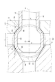
図2及び図3に示すように、接続頭部42は、第一湾曲部43と、第二湾曲部44と、直線部45と、を備える。なお、以下の説明において、燃料配管4の中心軸線を中心軸線Aといい、中心軸線Aを含む断面(図2に示す断面)を、基準断面Sという。
As shown in FIGS. 2 and 3, the
第一湾曲部43は、接続頭部42の先端部に位置して、接続部34(燃料分配管3)の内周面に形成された座面36に当接される部位である。接続頭部42の先端部は、接続頭部42における管部本体41と反対側の端部である。第一湾曲部43は、基準断面Sにおいて円状に湾曲している。つまり、第一湾曲部43は、中心軸線A上の点を中心とした球状に形成されている。なお、第一湾曲部43は、管部本体41の先端部を塑性加工することにより形成されているため、第一湾曲部43の外周面及び内周面の両面が、基準断面Sにおいて円状に湾曲している。
The first
第二湾曲部44は、接続頭部42の基端部に位置して、袋ナット5の内周面に形成された係止面54に係止される部位である。接続頭部42の基端部は、接続頭部42における管部本体41側の端部である。第二湾曲部44は、基準断面Sにおいて円状に湾曲している。つまり、第二湾曲部44は、中心軸線A上の点を中心とした球状に形成されている。なお、第二湾曲部44は、管部本体41の先端部を塑性加工することにより形成されているため、第二湾曲部44の外周面及び内周面の両面が、基準断面Sにおいて円状に湾曲している。
The second
第一湾曲部43の外周面と第二湾曲部44の外周面とは、中心軸線A上の点Oを曲率中心とした同心円の関係となっている。この場合、第一湾曲部43の外周面の半径と第二湾曲部44の外周面の半径とは同じであってもよいが、第一湾曲部43の外周面の半径は、第二湾曲部44の外周面の半径よりも小さいことが好ましい。
The outer peripheral surface of the first
直線部45は、第一湾曲部43と第二湾曲部44とを接続する部位である。このため、接続頭部42は、先端部から基端部に向けて、第一湾曲部43、直線部45、及び第二湾曲部44の順に配置されている。直線部45は、基準断面Sにおいて直線状に延びている。つまり、直線部45は、基準断面Sにおいて、第一湾曲部43と第二湾曲部44との間の直線状に延びている部分をいう。ここで、基準断面Sにおいて直線状に延びている部分とは、基準断面Sにおいて実質的に直線状に延びている部分をいい、具体的には、基準断面Sにおける外周面又は内周面の平面度が2mm以内となる部分をいう。つまり、基準断面Sにおいて外周面又は内周面の平面度が2mm以内にある部分が、直線部45となる。なお、基準断面Sでは接続頭部42の外周面及び内周面が線で表わされるため、基準断面Sにおいて、外周面又は内周面が2mmの間隔で平行に配置された2本の直線の間に位置する部分が、直線部45となる。この場合、上記の平面度は、1.5mm以内であることが好ましく、1.0mm以内であることが更に好ましい。なお、直線部45は、管部本体41の先端部を塑性加工することにより形成されるため、直線部45の外周面及び内周面の両面が、基準断面Sにおいて直線状に延びている。直線部45の詳細については、後述する。
The
上述したように、接続頭部42は、管部本体41の先端部を塑性加工して形成されることから、接続頭部42における直線部45の内径nは、管部本体41の内径mよりも大きい。管部本体41の内径mに対する直線部45の内径nの比は、特に限定されないが、例えば、1.1≦n/m≦2.5とすることが好ましく、1.1≦n/m≦2.0とすることが更に好ましい。
As described above, since the
袋ナット5は、内周面側に接続頭部42が挿入されるように、半径方向中心部に穴が形成された円筒状に形成されている。袋ナット5は、ネジ部51と、係止部52と、を備える。
The
ネジ部51は、袋ナット5の一方端面5a側の端部に形成されており、係止部52は、袋ナット5の他方端面5b側の端部に形成されている。袋ナット5の一方端面5aとは、袋ナット5の中心軸線方向における両端面のうち、燃料分配管3側の端面をいう。袋ナット5の他方端面5bとは、袋ナット5の中心軸線方向における両端面のうち、燃料配管4側(燃料分配管3とは反対側)の端面をいう。
The
ネジ部51の内周面には、雌ネジ53が刻設されている。雌ネジ53は、接続部34の雄ネジ35と螺合されることで、袋ナット5により燃料配管4を燃料分配管3に締結するための部位である。
A
係止部52の内周面には、係止面54が形成されている。係止面54は、他方端面5b側から袋ナット5に挿入された接続頭部42を、一方端面5a側から係止するための部位である。係止面54は、一方端面5a側から他方端面5b側に向かうに従い拡径するテーパ状(漏斗状)に形成されており、接続頭部42の管軸(中心軸線)を通る断面が直線となっている。接続頭部42の管軸に対する係止面54の傾斜角度は、例えば、60°〜80°とすることができる。
A locking
そして、袋ナット5により燃料配管4を燃料分配管3に締結する際は、他方端面5b側から袋ナット5に管部本体41を挿入した状態で、雄ネジ35に雌ネジ53を螺合する。すると、袋ナット5に挿入された接続頭部42の第二湾曲部44が係止面54に当接され、袋ナット5により接続頭部42が燃料分配管3側に引き寄せられる。そして、燃料分配管3に対する袋ナット5の軸力により、第一湾曲部43が座面36に圧接されるとともに、第二湾曲部44が係止面54に圧接される。これにより、袋ナット5により燃料分配管3と燃料配管4とが締結されて、燃料分配管3と燃料配管4とが接続固定される。
When the
次に、直線部45についてさらに詳しく説明する。
Next, the
図3及び図4に示すように、直線部45は、基準断面Sにおいて、中心軸線Aに対して、接続頭部42の先端に向けて広がるように傾斜している。つまり、直線部45は、中心軸線Aを中心とした円錐台の筒状に形成されている。上述したように、直線部45は、管部本体41の先端部を塑性加工することにより形成されるため、直線部45の外周面及び内周面の両面が、基準断面Sにおいて、中心軸線Aに対して、接続頭部42の先端に向けて広がるように傾斜している。基準断面Sにおいて、直線部45の外周面の延長線を直線L1とし、中心軸線Aに対して直線L1が接続頭部42の先端に向けて閉じる方向の角度を角度αとした場合に、角度αは0未満(α<0)となる。
As shown in FIGS. 3 and 4, in the reference cross section S, the
また、基準断面Sにおいて、第一湾曲部43が座面36に当接される点を点T1とし、第二湾曲部44が係止面54に当接される点を点T2とし、点T1と点T2とを結ぶ線分を線分L2とする。この場合、線分L2は、中心軸線Aに対して、接続頭部42の先端に向けて広がるように傾斜している。つまり、基準断面Sにおいて、中心軸線Aに対して線分L2が接続頭部42の先端に向けて閉じる方向の角度を角度βとした場合に、角度βは0未満(β<0)となっている。
Further, in the reference cross section S, a point where the first
また、基準断面Sにおける直線部45の長さを長さLとし、管部本体41の内径を内径mとした場合、長さL/内径mは、0.63以上(L/m≧0.63)となっている。基準断面Sにおける直線部45の長さLは、次のように求められる。基準断面Sにおいて、点Oを中心として第一湾曲部43の外周面を通る円を円C1とし、点Oを中心として第二湾曲部44の外周面を通る円を円C2とし、直線部45の外周面の延長線を直線L1とし、第一湾曲部43近傍における円C1と直線L1との交点を点P1とし、第二湾曲部44近傍における円C2と直線L1との交点を点P2とする。そして、点P1から点P2までの長さを、基準断面Sにおける直線部45の長さLとする。
When the length of the
以上説明したように、本実施形態に係る燃料配管4では、円状に湾曲している第一湾曲部43及び第二湾曲部44に応力が集中しやすい。しかしながら、第一湾曲部43と第二湾曲部44との間に直線部45が設けられているため、袋ナット5の軸力を、直線部45に分散させることができる。これにより、第一湾曲部43及び第二湾曲部44に発生する最大応力が小さくなるため、接続頭部42を増肉しなくても、接続頭部42の強度を向上させることができる。
As described above, in the
また、この燃料配管4では、接続頭部42が燃料分配管3の内周面に形成された座面36に当接されるのに対し、直線部45が接続頭部42の先端に向けて広がるため、直線部45の延在方向を、座面36に向けることができる。これにより、座面36から受ける反力を直線部45で受けることができる。また、座面36から受ける反力のうち、直線部45を曲げる方向の成分の力、つまり、直線部45に対して垂直な方向の成分の力を低減させることができる。その結果、接続頭部42に発生する最大応力が小さくなるため、接続頭部42の強度が更に向上する。
Further, in the
また、この燃料配管4では、接続頭部42と管部本体41の板厚が同じであるため、管部本体41の先端部を塑性加工することにより、接続頭部42を容易かつ低コストに製造することができる。
Further, in this
また、この燃料配管4では、袋ナット5の軸力は、座面36に当接される点T1及び係止面54に当接される点T2から接続頭部42に入力される。このため、当該点T1及び点T2を結ぶ線分L2が接続頭部42の先端に向けて広がることで、接続頭部42に入力される軸力の方向を、座面36に向けることができる。これにより、接続頭部の強度が更に向上する。
Further, in the
また、この燃料配管4では、L/mを0.63以上とすることで、接続頭部42における直線部の割合が相対的に大きくなり、接続頭部における第一湾曲部及び第二湾曲部の割合、つまり、円状の部分の割合が相対的に小さくなる。これにより、最大応力が発生する部分が、接続頭部42の基端部である管部本体41の近傍に位置することになるため、接続頭部42に生じる曲げモーメントが小さくなることで、接続頭部42の強度が更に向上する。
Further, in this
ここで、本発明者は、中心軸線Aに対する直線L1の角度αと、中心軸線Aに対する線分L2の角度βと、接続頭部42に発生する最大応力と、の関係についてシミュレーションした。シミュレーション結果を図5に示す。
Here, the present inventor simulated the relationship between the angle α of the straight line L1 with respect to the central axis A, the angle β of the line segment L2 with respect to the central axis A, and the maximum stress generated in the
図5に示すように、角度α<0である場合は、角度βに関わらず、角度α≧である場合に比べて、接続頭部42に発生する最大応力が小さくなった。この結果から、基準断面Sにおいて、直線部45が、中心軸線Aに対して、接続頭部42の先端に向けて広がるように傾斜していることで、接続頭部42に発生する最大応力が小さくなることが分かった。
As shown in FIG. 5, when the angle α<0, the maximum stress generated in the connecting
特に、角度α<0、且つ、角度β<0である場合は、接続頭部42に発生する最大応力が格段に小さくなった。この結果から、基準断面Sにおいて、直線部45、及び、第一湾曲部43が座面36に当接される点T1と第二湾曲部44が袋ナット5の係止面54に係止される点T2とを結んだ線分が、中心軸線Aに対して、接続頭部42の先端に向けて広がるように傾斜していることで、接続頭部42に発生する最大応力が格段に小さくなることが分かった。
In particular, when the angle α<0 and the angle β<0, the maximum stress generated in the
図3及び図4に示すように、基準断面Sにおける直線部45の長さを長さLとし、管部本体41の内径を内径mとした場合、長さL/内径mは、0.63以上(L/m≧0.63)となる。
As shown in FIGS. 3 and 4, when the length of the
基準断面Sにおける直線部45の長さLは、次のように求められる。基準断面Sにおいて、点Oを中心として第一湾曲部43の外周面を通る円を円C1とし、点Oを中心として第二湾曲部44の外周面を通る円を円C2とし、直線部45の外周面の延長線を直線L1とし、第一湾曲部43近傍における円C1と直線L1との交点を点P1とし、第二湾曲部44近傍における円C2と直線L1との交点を点P2とする。そして、点P1から点P2までの長さを、基準断面Sにおける直線部45の長さLとする。
The length L of the
ここで、本発明者は、中心軸線Aに対する直線L1の角度αと、直線部45の長さLと、接続頭部42に発生する最大応力と、の関係についてシミュレーションした。このシミュレーションでは、管部本体41の内径mを5.5mmとした。シミュレーション結果を図6に示す。なお、通常は、接続頭部42に発生する最大応力が460MPaを超えても、接続頭部42が変形しないと考えられる。しかしながら、図6では、接続頭部42の変形をより防止する観点から、基準となる応力を460MPaとした。
Here, the present inventor simulated the relationship between the angle α of the straight line L1 with respect to the central axis A, the length L of the
図6に示すように、直線部45の長さLが3.5mm未満である場合は、接続頭部42に発生する最大応力が460MPaを超えるケースが散見されたが、直線部45の長さLが3.5mm以上である場合は、接続頭部42に発生する最大応力が460MPaを超えなかった。この結果から、管部本体41の内径mが5.5mmである場合に、直線部45の長さLが3.5mm以上であれば、接続頭部42の変形をより防止できることが分かった。
As shown in FIG. 6, when the length L of the
また、本発明者は、接続頭部42の任意の点に発生する応力と、直線部45の長さLと、の関係についてシミュレーションした。このシミュレーションでは、管部本体41の内径mを5.5mmとした。シミュレーション結果を図7に示す。なお、図7でも、図6と同様に、接続頭部42の変形をより防止する観点から、基準となる応力を460MPaとした。
The present inventor also simulated the relationship between the stress generated at an arbitrary point of the
図7に示すように、直線部45の長さLが3.5mm未満である場合は、接続頭部42の任意の点に発生する応力が460MPaを超えるケースが散見されたが、直線部45の長さLが3.5mm以上である場合は、接続頭部42の任意の点に発生する応力が460MPaを超えなかった。この結果から、管部本体41の内径mが5.5mmである場合に、直線部45の長さLが3.5mm以上であれば、接続頭部42の変形をより防止できることが分かった。
As shown in FIG. 7, when the length L of the
このように、図6及び図7の何れも、管部本体41の内径mが5.5mmである場合に、直線部45の長さLが3.5mm以上とすることで、接続頭部42に発生する応力を460MPa未満に抑えられた。そして、この管部本体41の内径mに対する直線部45の長さLの比を計算すると、L/m≒0.63となる。このため、長さL/内径mを0.63以上とすることで、接続頭部42の変形をより防止できることが推察される。
As described above, in both FIG. 6 and FIG. 7, when the inner diameter m of the tube
以上、本発明の好適な実施形態について説明したが、本発明は上記実施形態に限定されるものではない。 Although the preferred embodiment of the present invention has been described above, the present invention is not limited to the above embodiment.
1…燃料分配供給装置、2…燃料噴射装置、3…燃料分配管、4…燃料配管、5…袋ナット、5a…一方端面、5b…他方端面、31…管部、32…カップ部、33…蓋部、34…接続部、35…雄ネジ、36…座面、41…管部本体、42…接続頭部、43…第一湾曲部、44…第二湾曲部、45…直線部、51…ネジ部、52…係止部、53…雌ネジ、54…係止面、A…中心軸線。
DESCRIPTION OF
Claims (5)
管部本体と、
袋ナットにより前記燃料分配管に締結される接続頭部と、を備え、
前記接続頭部は、
前記燃料配管の中心軸線を含む基準断面において円状に湾曲し、前記燃料分配管の内周面に形成された座面に当接される第一湾曲部と、
前記基準断面において円状に湾曲し、前記袋ナットの内周面に形成された係止面に係止される第二湾曲部と、
前記基準断面において直線状に延びて、前記第一湾曲部と前記第二湾曲部とを接続する直線部と、を有し、
前記基準断面において、前記直線部は、前記中心軸線に対して、前記接続頭部の先端に向けて広がるように傾斜している、
燃料配管。 A fuel pipe connected to a fuel distribution pipe for supplying and distributing fuel to a plurality of fuel injectors,
With the tube body,
A connection head portion fastened to the fuel distribution pipe by a cap nut,
The connection head is
A first curved portion that is curved in a circular shape in a reference cross section including the central axis of the fuel pipe, and abuts on a seat surface formed on the inner peripheral surface of the fuel distribution pipe;
A second curved portion that is curved in a circular shape in the reference cross section and that is locked to a locking surface formed on the inner peripheral surface of the cap nut,
The extend linearly in the reference section, have a, a linear portion which connects the said first curved portion and the second curved portion,
In the reference cross section, the linear portion is inclined with respect to the central axis line so as to spread toward the tip of the connection head.
Fuel piping.
管部本体と、
袋ナットにより前記燃料分配管に締結される接続頭部と、を備え、
前記接続頭部は、
前記燃料配管の中心軸線を含む基準断面において円状に湾曲し、前記燃料分配管の内周面に形成された座面に当接される第一湾曲部と、
前記基準断面において円状に湾曲し、前記袋ナットの内周面に形成された係止面に係止される第二湾曲部と、
前記基準断面において直線状に延びて、前記第一湾曲部と前記第二湾曲部とを接続する直線部と、を有し、
前記基準断面において、前記第一湾曲部が前記座面に当接される点と前記第二湾曲部が前記係止面に当接される点とを結んだ線分は、前記中心軸線に対して、前記接続頭部の先端に向けて広がるように傾斜している、
燃料配管。 A fuel pipe connected to a fuel distribution pipe for supplying and distributing fuel to a plurality of fuel injectors,
With the tube body,
A connection head part fastened to the fuel distribution pipe by a cap nut,
The connection head is
A first curved portion that is curved in a circular shape in a reference cross section including the central axis of the fuel pipe, and is in contact with a seat surface formed on the inner peripheral surface of the fuel distribution pipe,
A second curved portion that is curved in a circle in the reference cross section and that is locked to a locking surface formed on the inner peripheral surface of the cap nut,
The extend linearly in the reference section, have a, a linear portion which connects the said first curved portion and the second curved portion,
In the reference cross section, a line segment that connects the point where the first curved portion contacts the seating surface and the point where the second curved portion contacts the locking surface with respect to the central axis. , Is inclined so as to spread toward the tip of the connection head,
Fuel piping.
請求項1又は2に記載の燃料配管。 The inner diameter of the straight portion is larger than the inner diameter of the tube body,
The fuel pipe according to claim 1 or 2.
請求項1〜3の何れか一項に記載の燃料配管。 The plate thickness of the connection head is the same as the plate thickness of the tube body,
The fuel pipe according to any one of claims 1 to 3.
請求項1〜4の何れか一項に記載の燃料配管。
When the length of the linear portion in the reference cross section is L and the inner diameter of the tube body is m, L/m is 0.63 or more.
Fuel pipe according to any one of claims 1-4.
Priority Applications (6)
| Application Number | Priority Date | Filing Date | Title |
|---|---|---|---|
| JP2016213547A JP6734179B2 (en) | 2016-10-31 | 2016-10-31 | Fuel piping |
| MX2019004838A MX2019004838A (en) | 2016-10-31 | 2017-07-26 | Fuel pipe. |
| US16/346,294 US11143152B2 (en) | 2016-10-31 | 2017-07-26 | Fuel pipe |
| PCT/JP2017/027076 WO2018078978A1 (en) | 2016-10-31 | 2017-07-26 | Fuel pipe |
| EP17865438.0A EP3533991B1 (en) | 2016-10-31 | 2017-07-26 | Fuel pipe |
| CN201780064503.7A CN109844301B (en) | 2016-10-31 | 2017-07-26 | Fuel distribution pipe |
Applications Claiming Priority (1)
| Application Number | Priority Date | Filing Date | Title |
|---|---|---|---|
| JP2016213547A JP6734179B2 (en) | 2016-10-31 | 2016-10-31 | Fuel piping |
Publications (3)
| Publication Number | Publication Date |
|---|---|
| JP2018071466A JP2018071466A (en) | 2018-05-10 |
| JP2018071466A5 JP2018071466A5 (en) | 2019-06-20 |
| JP6734179B2 true JP6734179B2 (en) | 2020-08-05 |
Family
ID=62024693
Family Applications (1)
| Application Number | Title | Priority Date | Filing Date |
|---|---|---|---|
| JP2016213547A Active JP6734179B2 (en) | 2016-10-31 | 2016-10-31 | Fuel piping |
Country Status (6)
| Country | Link |
|---|---|
| US (1) | US11143152B2 (en) |
| EP (1) | EP3533991B1 (en) |
| JP (1) | JP6734179B2 (en) |
| CN (1) | CN109844301B (en) |
| MX (1) | MX2019004838A (en) |
| WO (1) | WO2018078978A1 (en) |
Families Citing this family (1)
| Publication number | Priority date | Publication date | Assignee | Title |
|---|---|---|---|---|
| GB2612974A (en) * | 2021-11-17 | 2023-05-24 | Delphi Tech Ip Ltd | Fuel-rail assembly |
Family Cites Families (27)
| Publication number | Priority date | Publication date | Assignee | Title |
|---|---|---|---|---|
| US2494128A (en) * | 1945-11-14 | 1950-01-10 | Nat Supply Co | Method of increasing the axial tensile strength of threaded joints |
| DE2631984A1 (en) * | 1976-07-16 | 1978-01-19 | Schenk Horst | Screw coupling with welding nozzle for pipework - has nozzle thicker part contacting sealed spherical seat in socket |
| US4266577A (en) * | 1979-07-25 | 1981-05-12 | Usui Kokusai Sangyo Kabushiki Kaisha | Collared fuel injection pipe for engines |
| US5529349A (en) * | 1993-08-25 | 1996-06-25 | Itt Corporation | Mounting apparatus with reduced resistance bead seal |
| DE19701561C2 (en) * | 1997-01-17 | 1998-10-22 | Daimler Benz Ag | Double-cone coupling nipple of a steel pipe |
| JP4456192B2 (en) * | 1999-02-05 | 2010-04-28 | 臼井国際産業株式会社 | Connection structure between metal pipe and mating parts |
| JP2003021018A (en) | 2001-07-09 | 2003-01-24 | Bosch Automotive Systems Corp | Connection device for rail and injection pipe |
| JP2004019541A (en) | 2002-06-17 | 2004-01-22 | Denso Corp | High-pressure fuel injection pipe |
| DE202004012959U1 (en) | 2004-08-18 | 2004-10-14 | Kohlhage Verbindungstechnik Gmbh & Co. Kg | Spherical liner-type screw connection for e.g. fuel injection lines in motor vehicles has upset spherical liner at end of pipe, with conical contact area to engage on union nut |
| DE102005024053A1 (en) * | 2005-05-25 | 2006-11-30 | Robert Bosch Gmbh | Connection System |
| JP2007077807A (en) | 2005-09-09 | 2007-03-29 | Usui Kokusai Sangyo Kaisha Ltd | Connection head of fuel pipe in direct-injection fuel pipe connection structure and head forming method |
| DE102005045731B4 (en) | 2005-09-23 | 2010-09-23 | Benteler Automobiltechnik Gmbh | Connecting arrangement for pipes |
| DE102006015652B3 (en) | 2006-04-04 | 2007-07-19 | Winkelmann Powertrain Components Gmbh & Co. Kg | Fitting to connect a pipe section at a screw connection, in a motor fuel line, has a cap nut with a spring shoulder to press the thickened pipe end against a sealing seat under spring tension |
| DE102007019464A1 (en) | 2007-04-25 | 2008-10-30 | Elringklinger Ag | Sealing arrangement comprises a sealing element sleeve which slides on a first end region of a connecting element and held in the assembled state with an elastic holding element in the radial direction on a region of the connecting element |
| DE102007046203A1 (en) | 2007-09-27 | 2008-05-15 | Audi Ag | Connecting arrangement for connecting front ends of pipe line to distributor of fuel or hydraulic system, has nut pressing during tightening against pressing surface, where sealing surface and pressing surface have center of curvature |
| JP5178176B2 (en) * | 2007-12-17 | 2013-04-10 | 臼井国際産業株式会社 | Connecting head structure of high-pressure fuel injection pipe |
| US10215315B2 (en) * | 2008-09-05 | 2019-02-26 | Parker-Hannifin Corporation | Tube compression fitting and flared fitting used with connection body and method of making same |
| US8196967B2 (en) | 2009-02-04 | 2012-06-12 | Robert Bosch Gmbh | Improvements to high pressure fuel fittings |
| JP5455013B2 (en) * | 2009-03-24 | 2014-03-26 | 臼井国際産業株式会社 | High pressure fuel injection pipe having connecting head and method of manufacturing the same |
| DE102009041056A1 (en) * | 2009-09-10 | 2011-03-24 | Voss Fluid Gmbh | Pipe fitting and method of making the same |
| JP5394206B2 (en) | 2009-11-20 | 2014-01-22 | 三桜工業株式会社 | Piping fastening structure |
| EP2360405A1 (en) * | 2010-02-19 | 2011-08-24 | TI Automotive (Heidelberg) GmbH | Tube connection device |
| JP5513191B2 (en) * | 2010-03-19 | 2014-06-04 | 株式会社ケーヒン | Fuel supply device for in-cylinder fuel injection valve |
| DE102011002996A1 (en) | 2011-01-21 | 2012-07-26 | Robert Bosch Gmbh | Fuel injector with improved high pressure connection |
| JP5758640B2 (en) * | 2011-02-04 | 2015-08-05 | 株式会社フロウエル | Tube fitting |
| AU2013244568B2 (en) * | 2012-04-02 | 2016-05-12 | Mitsubishi Electric Corporation | Pipe Joint, Air Conditioner, Connecting Pipe, Method for Producing Connecting Pipe and Connection Method |
| JP6730089B2 (en) * | 2016-05-19 | 2020-07-29 | 三桜工業株式会社 | Fuel distributor |
-
2016
- 2016-10-31 JP JP2016213547A patent/JP6734179B2/en active Active
-
2017
- 2017-07-26 MX MX2019004838A patent/MX2019004838A/en unknown
- 2017-07-26 WO PCT/JP2017/027076 patent/WO2018078978A1/en unknown
- 2017-07-26 US US16/346,294 patent/US11143152B2/en active Active
- 2017-07-26 CN CN201780064503.7A patent/CN109844301B/en active Active
- 2017-07-26 EP EP17865438.0A patent/EP3533991B1/en active Active
Also Published As
| Publication number | Publication date |
|---|---|
| EP3533991A4 (en) | 2020-06-03 |
| WO2018078978A1 (en) | 2018-05-03 |
| CN109844301A (en) | 2019-06-04 |
| MX2019004838A (en) | 2019-06-20 |
| JP2018071466A (en) | 2018-05-10 |
| EP3533991B1 (en) | 2021-09-08 |
| US11143152B2 (en) | 2021-10-12 |
| US20200182209A1 (en) | 2020-06-11 |
| CN109844301B (en) | 2021-10-15 |
| EP3533991A1 (en) | 2019-09-04 |
Similar Documents
| Publication | Publication Date | Title |
|---|---|---|
| US7963571B2 (en) | Tubing configuration and sealing method for high pressure tubing on high pressure fuel systems | |
| CN107250641A (en) | Sealing structure for gaseous fuel | |
| US20170342950A1 (en) | Threaded fuel rails | |
| US20180094614A1 (en) | Fuel pipe connecting head and fuel pipe | |
| EP3290683A1 (en) | Terminal seal structure for fuel rail for gasoline direct-injection engine | |
| US10352485B2 (en) | Pipe connecting device | |
| JP6734179B2 (en) | Fuel piping | |
| US9841128B2 (en) | Tube fitting assembly | |
| EP3179089A1 (en) | End-sealing structure for fuel rail for gasoline direct injection engine | |
| JP6730089B2 (en) | Fuel distributor | |
| KR20170024091A (en) | Terminal seal structure for direct-injection gasoline engine fuel rail | |
| JP6383392B2 (en) | Spray nozzle | |
| JP2010216431A (en) | Common rail | |
| CN106662059B (en) | Fuel rail with end seal configuration | |
| US20100301601A1 (en) | Fluid coupling for a direct injection engine | |
| DE102016015301A1 (en) | Conduit device for a motor vehicle | |
| JP3199795U (en) | Fitting for piping | |
| JP2017096106A (en) | Fuel distribution pipe | |
| KR20160124961A (en) | Valve seat by forging-processing for check valve | |
| TH89569B (en) | High-pressure fuel injection hoses with their connectors and bent parts and the method of their manufacture. |
Legal Events
| Date | Code | Title | Description |
|---|---|---|---|
| A521 | Request for written amendment filed |
Free format text: JAPANESE INTERMEDIATE CODE: A523 Effective date: 20190515 |
|
| A621 | Written request for application examination |
Free format text: JAPANESE INTERMEDIATE CODE: A621 Effective date: 20190515 |
|
| A131 | Notification of reasons for refusal |
Free format text: JAPANESE INTERMEDIATE CODE: A131 Effective date: 20200422 |
|
| A521 | Request for written amendment filed |
Free format text: JAPANESE INTERMEDIATE CODE: A523 Effective date: 20200608 |
|
| TRDD | Decision of grant or rejection written | ||
| A01 | Written decision to grant a patent or to grant a registration (utility model) |
Free format text: JAPANESE INTERMEDIATE CODE: A01 Effective date: 20200616 |
|
| A61 | First payment of annual fees (during grant procedure) |
Free format text: JAPANESE INTERMEDIATE CODE: A61 Effective date: 20200709 |
|
| R150 | Certificate of patent or registration of utility model |
Ref document number: 6734179 Country of ref document: JP Free format text: JAPANESE INTERMEDIATE CODE: R150 |
|
| R250 | Receipt of annual fees |
Free format text: JAPANESE INTERMEDIATE CODE: R250 |