JP6730397B2 - Coil parts and electronic equipment - Google Patents
Coil parts and electronic equipment Download PDFInfo
- Publication number
- JP6730397B2 JP6730397B2 JP2018185572A JP2018185572A JP6730397B2 JP 6730397 B2 JP6730397 B2 JP 6730397B2 JP 2018185572 A JP2018185572 A JP 2018185572A JP 2018185572 A JP2018185572 A JP 2018185572A JP 6730397 B2 JP6730397 B2 JP 6730397B2
- Authority
- JP
- Japan
- Prior art keywords
- core
- adhesive
- plate core
- coil
- base portion
- Prior art date
- Legal status (The legal status is an assumption and is not a legal conclusion. Google has not performed a legal analysis and makes no representation as to the accuracy of the status listed.)
- Active
Links
Images


Classifications
-
- H—ELECTRICITY
- H01—ELECTRIC ELEMENTS
- H01F—MAGNETS; INDUCTANCES; TRANSFORMERS; SELECTION OF MATERIALS FOR THEIR MAGNETIC PROPERTIES
- H01F17/00—Fixed inductances of the signal type
- H01F17/04—Fixed inductances of the signal type with magnetic core
- H01F17/045—Fixed inductances of the signal type with magnetic core with core of cylindric geometry and coil wound along its longitudinal axis, i.e. rod or drum core
-
- H—ELECTRICITY
- H01—ELECTRIC ELEMENTS
- H01F—MAGNETS; INDUCTANCES; TRANSFORMERS; SELECTION OF MATERIALS FOR THEIR MAGNETIC PROPERTIES
- H01F27/00—Details of transformers or inductances, in general
- H01F27/24—Magnetic cores
- H01F27/26—Fastening parts of the core together; Fastening or mounting the core on casing or support
- H01F27/263—Fastening parts of the core together
-
- H—ELECTRICITY
- H01—ELECTRIC ELEMENTS
- H01F—MAGNETS; INDUCTANCES; TRANSFORMERS; SELECTION OF MATERIALS FOR THEIR MAGNETIC PROPERTIES
- H01F27/00—Details of transformers or inductances, in general
- H01F27/24—Magnetic cores
- H01F27/26—Fastening parts of the core together; Fastening or mounting the core on casing or support
- H01F27/266—Fastening or mounting the core on casing or support
-
- H—ELECTRICITY
- H01—ELECTRIC ELEMENTS
- H01F—MAGNETS; INDUCTANCES; TRANSFORMERS; SELECTION OF MATERIALS FOR THEIR MAGNETIC PROPERTIES
- H01F27/00—Details of transformers or inductances, in general
- H01F27/28—Coils; Windings; Conductive connections
- H01F27/2823—Wires
-
- H—ELECTRICITY
- H01—ELECTRIC ELEMENTS
- H01F—MAGNETS; INDUCTANCES; TRANSFORMERS; SELECTION OF MATERIALS FOR THEIR MAGNETIC PROPERTIES
- H01F27/00—Details of transformers or inductances, in general
- H01F27/28—Coils; Windings; Conductive connections
- H01F27/29—Terminals; Tapping arrangements for signal inductances
- H01F27/292—Surface mounted devices
-
- H—ELECTRICITY
- H01—ELECTRIC ELEMENTS
- H01F—MAGNETS; INDUCTANCES; TRANSFORMERS; SELECTION OF MATERIALS FOR THEIR MAGNETIC PROPERTIES
- H01F3/00—Cores, Yokes, or armatures
- H01F3/10—Composite arrangements of magnetic circuits
-
- H—ELECTRICITY
- H01—ELECTRIC ELEMENTS
- H01F—MAGNETS; INDUCTANCES; TRANSFORMERS; SELECTION OF MATERIALS FOR THEIR MAGNETIC PROPERTIES
- H01F41/00—Apparatus or processes specially adapted for manufacturing or assembling magnets, inductances or transformers; Apparatus or processes specially adapted for manufacturing materials characterised by their magnetic properties
- H01F41/02—Apparatus or processes specially adapted for manufacturing or assembling magnets, inductances or transformers; Apparatus or processes specially adapted for manufacturing materials characterised by their magnetic properties for manufacturing cores, coils, or magnets
- H01F41/0206—Manufacturing of magnetic cores by mechanical means
- H01F41/0246—Manufacturing of magnetic circuits by moulding or by pressing powder
-
- H—ELECTRICITY
- H01—ELECTRIC ELEMENTS
- H01F—MAGNETS; INDUCTANCES; TRANSFORMERS; SELECTION OF MATERIALS FOR THEIR MAGNETIC PROPERTIES
- H01F3/00—Cores, Yokes, or armatures
- H01F3/10—Composite arrangements of magnetic circuits
- H01F2003/106—Magnetic circuits using combinations of different magnetic materials
-
- H—ELECTRICITY
- H01—ELECTRIC ELEMENTS
- H01F—MAGNETS; INDUCTANCES; TRANSFORMERS; SELECTION OF MATERIALS FOR THEIR MAGNETIC PROPERTIES
- H01F17/00—Fixed inductances of the signal type
- H01F2017/0093—Common mode choke coil
Landscapes
- Engineering & Computer Science (AREA)
- Power Engineering (AREA)
- Microelectronics & Electronic Packaging (AREA)
- Chemical & Material Sciences (AREA)
- Composite Materials (AREA)
- Manufacturing & Machinery (AREA)
- Coils Or Transformers For Communication (AREA)
Description
本発明は、コイル部品及び電子機器に関する。 The present invention relates to a coil component and electronic equipment.
近年、移動体機器などの電子機器の回路基板に実装されるコイル部品は、落下などの衝撃に耐え得る、高い衝撃耐性が求められている。コイル部品の一例として、ドラムコアと板コアを含んで形成される巻線型のコモンモードチョークコイルが知られている。コモンモードチョークコイルでは、高い衝撃耐性を実現するために、ドラムコアと板コアとの接着を強固にすることが求められている。例えば、ドラムコアを構成する鍔部と板コアとを接着させる場合に、鍔部の接着面に溝を形成し、この溝内に接着剤を充填させることで、鍔部と板コアを確実に接着させることが知られている(例えば、特許文献1)。また、鍔部の接着面に隙間を設け、この隙間に接着剤を配置することで、少ない接着剤で高い接着強度が得られることが知られている(例えば、特許文献2)。 In recent years, a coil component mounted on a circuit board of an electronic device such as a mobile device is required to have high impact resistance capable of withstanding an impact such as a drop. As an example of the coil component, a winding type common mode choke coil formed by including a drum core and a plate core is known. In the common mode choke coil, in order to realize high impact resistance, it is required to firmly bond the drum core and the plate core. For example, when adhering the flange portion and the plate core forming the drum core to each other, by forming a groove on the adhesive surface of the flange portion and filling the groove with an adhesive, the flange portion and the plate core are surely adhered. It is known to do so (for example, Patent Document 1). Further, it is known that a high adhesive strength can be obtained with a small amount of adhesive by providing a gap on the adhesive surface of the flange and disposing the adhesive in this gap (for example, Patent Document 2).
磁性材料を含んで形成される第1基体部と第2基体部が接着剤で接着されたコイル部品において、接着剤の量が少ない場合では、第1基体部と第2基体部の接合強度の低下が生じてしまう。反対に、接着剤の量が多い場合では、第1基体部と第2基体部の間隔のバラツキが大きくなり易く、また特に小型のコイル部品では接着剤がはみ出してしまうなどにより、電気的特性と機械的特性の低下が生じてしまう。 In a coil component in which a first base portion and a second base portion formed by including a magnetic material are bonded with an adhesive, when the amount of the adhesive is small, the bonding strength of the first base portion and the second base portion is There will be a drop. On the other hand, when the amount of the adhesive is large, the variation in the distance between the first base portion and the second base portion is likely to be large, and particularly in the case of a small coil component, the adhesive is squeezed out, so that the electrical characteristics are The mechanical properties are deteriorated.
本発明は、上記課題に鑑みなされたものであり、良好な接着強度と良好なインダクタンス特性の両立を図ることを目的とする。 The present invention has been made in view of the above problems, and an object thereof is to achieve both good adhesive strength and good inductance characteristics.
本発明は、磁性材料を含んで形成される第1基体部及び第2基体部と、有機材料と、前記磁性材料とは異なる無機粒子であるフィラーと、を含有し、前記第1基体部と前記第2基体部を接着させる接着剤と、絶縁被膜を有する導体で形成されたコイルと、前記コイルに電気的に接続された電極と、を備え、前記第1基体部の前記接着剤を介して前記第2基体部に接着する面の表面粗さは、前記フィラーの平均粒径よりも大きい、コイル部品である。 The present invention includes a first base portion and a second base portion which is formed to include a magnetic material, and an organic material, containing a filler are different inorganic particles and the magnetic material, and the first base portion An adhesive for adhering the second base portion, a coil formed of a conductor having an insulating coating, and an electrode electrically connected to the coil are provided, and the adhesive for the first base portion is interposed therebetween. The surface roughness of the surface that adheres to the second base portion is larger than the average particle diameter of the filler, and is a coil component.
上記構成において、前記フィラーはシリカ粒子又はジルコニア粒子である構成とすることができる。上記構成において、前記第2基体部の前記接着剤を介して前記第1基体部に接着する面の表面粗さは、前記第1基体部の前記接着剤を介して前記第2基体部に接着する前記面の表面粗さよりも小さい構成とすることができる。 In the above structure, the filler may be silica particles or zirconia particles. In the above structure, the surface roughness of the surface of the second base portion that is bonded to the first base portion via the adhesive is such that the surface roughness of the surface of the second base portion is bonded to the second base portion via the adhesive. The surface roughness can be smaller than the surface roughness of the surface.
上記構成において、前記第1基体部と前記第2基体部は、前記接着剤を間に挟む面の一部で直接接触している構成とすることができる。 In the above configuration, the first base portion and the second base portion may be in direct contact with each other on a part of a surface sandwiching the adhesive.
上記構成において、前記第1基体部は、前記導体が巻回される軸部と前記軸部の両端に設けられた鍔部とを有するドラムコアであり、前記第2基体部は、前記軸部の両端に設けられた2つの前記鍔部に接着した板状の板コアであり、前記接着剤は、前記鍔部と前記板コアとを接着する構成とすることができる。 In the above configuration, the first base body is a drum core having a shaft around which the conductor is wound and flanges provided at both ends of the shaft, and the second base is a shaft core of the shaft. The plate-shaped plate core is adhered to the two flange portions provided at both ends, and the adhesive may be configured to adhere the flange portion and the plate core.
上記構成において、前記コイルのコイル軸方向における前記板コアの長さは、前記コイル軸方向における前記ドラムコアの長さよりも長い構成とすることができる。 In the above configuration, the length of the plate core in the coil axis direction of the coil may be longer than the length of the drum core in the coil axis direction.
上記構成において、前記鍔部の前記接着剤を介して前記板コアに接着する面の角部にR形状が形成され、前記コイル軸方向における前記板コアの長さと前記ドラムコアの長さとの差は、前記鍔部の前記R形状におけるR寸法よりも大きい構成とすることができる。 In the above configuration, an R shape is formed at a corner portion of a surface of the collar portion that is bonded to the plate core via the adhesive, and a difference between a length of the plate core and a length of the drum core in the coil axis direction is The R dimension of the flange portion may be larger than the R dimension of the collar portion.
上記構成において、前記板コア及び前記軸部の磁性材料の充填率は、前記鍔部の磁性材料の充填率よりも大きい構成とすることができる。 In the above configuration, the filling rate of the magnetic material of the plate core and the shaft section may be larger than the filling rate of the magnetic material of the collar section.
上記構成において、前記コイルのコイル軸方向における前記板コアの長さは3.2mm以下である構成とすることができる。 In the above configuration, the length of the plate core in the coil axis direction of the coil may be 3.2 mm or less.
本発明は、上記記載のコイル部品と、前記コイル部品が実装された回路基板と、を備える、電子機器である。 The present invention is an electronic device including the coil component described above and a circuit board on which the coil component is mounted.
本発明によれば、良好な接着強度と良好なインダクタンス特性の両立を図ることができる。 According to the present invention, both good adhesive strength and good inductance characteristics can be achieved.
以下、図面を参照して、本発明の実施例について説明する。 Embodiments of the present invention will be described below with reference to the drawings.
以下、図面を参照して、本発明の実施例について説明する。コイル部品は、磁性材料を含んで形成される第1基体部及び第2基体部と、有機材料とフィラーを含有する接着剤と、絶縁被膜を有する導体で形成された引出部を含むコイルと、コイルと電気的に接続された電極により構成される。 Embodiments of the present invention will be described below with reference to the drawings. The coil component includes a first base portion and a second base portion formed of a magnetic material, an adhesive containing an organic material and a filler, and a coil including a lead portion formed of a conductor having an insulating coating. It is composed of an electrode electrically connected to the coil.
図1は、実施例1に係るコイル部品の斜視図である。実施例1では、コイル部品としてコモンモードチョークコイルを例に説明する。なお、図1において、鍔部14の回路基板に実装される下面20及び下面20とは反対側の上面22と平行な方向であって、コイル50を形成する導線52の周方向をX軸方向とし、コイル50のコイル軸方向をY軸方向とし、X軸及びY軸に垂直な方向をZ軸方向とする。図1のように、実施例1のコイル部品100は、ドラムコア10と、板コア30と、コイル50と、複数の電極70と、を備える。
FIG. 1 is a perspective view of a coil component according to the first embodiment. In the first embodiment, a common mode choke coil will be described as an example of the coil component. Note that, in FIG. 1, the circumferential direction of the conducting
ドラムコア10は、軸部12と、軸部12の軸方向の両端に設けられた1対の鍔部14と、を含む。軸部12は、例えば円柱形状又は角柱形状をしている。鍔部14は、例えば直方体形状をしている。軸部12は、例えば鍔部14の軸部12が接続する面の中心部に接続している。鍔部14は、回路基板に実装される側の下面20と、下面20とは反対側の上面22と、を有する。
The
ドラムコア10は、磁性体材料を含んで形成されている。例えば、ドラムコア10は、Ni−Zn系又はMn−Zn系のフェライト材料、Fe−Si−Cr系、Fe−Si−Al系、又はFe−Si−Cr−Al系などの軟磁性合金材料、Fe又はNiなどの磁性金属材料、アモルファス磁性金属材料、或いはナノ結晶磁性金属材料を含んで形成されている。フェライト材料で形成される場合、ドラムコア10はフェライト材料を焼結することで形成してもよい。この場合、ドラムコア10は、焼結反応により緻密化している。金属磁性粒子で形成される場合、ドラムコア10は金属磁性粒子を樹脂で固めることで形成してもよいし、金属磁性粒子の表面に形成された絶縁膜が互いに結合することで形成してもよい。この場合、ドラムコア10は、樹脂又は絶縁膜によって磁性粒子が結合されるため、磁性粒子の形状はほぼ維持されている。
The
板コア30は、軸部12を跨いで1対の鍔部14間を連結することができるように、例えば2つの平面を持ち、この平面は長方形形状をしている。板コア30は、例えば直方体形状をしている。板コア30は、下面32が鍔部14の上面22に接着剤40で接着されている。板コア30は、磁性体材料を含んで形成されている。例えば、板コア30は、ドラムコア10と同様に、フェライト材料で形成される場合、フェライト材料を焼結することで形成してもよい。金属磁性粒子で形成される場合、金属磁性粒子を樹脂で固めることで形成してもよいし、金属磁性粒子の表面に形成された絶縁膜が互いに結合することで形成してもよい。
The
ドラムコア10と板コア30は、同じ磁性材料で形成されていてもよいし、異なる磁性材料で形成されていてもよい。なお、ドラムコア10は、特許請求の範囲における第1基体部に相当し、板コア30は、特許請求の範囲における第2基体部に相当する。
The
ここで、ドラムコア10の鍔部14と板コア30との接合部分について説明する。図2(a)は、実施例1に係るコイル部品の断面図、図2(b)は、図2(a)の領域Aの拡大図である。なお、図2(a)では、図の明瞭化のために、コイル50の図示は省略している。図2(a)及び図2(b)のように、鍔部14の上面22と板コア30の下面32との間に接着剤40が設けられている。接着剤40は硬化されていて、鍔部14と板コア30とを固定する固定部となっている。鍔部14の上面22と板コア30の下面32とを接着する接着剤40は、樹脂42とフィラー44を含んで形成されている。接着剤40中にフィラー44が含まれることで、機械的強度を向上させることができる。樹脂42は、熱硬化性の樹脂であり、例えばエポキシ樹脂、シリコン樹脂、又はフェノール樹脂を用いることができる。例えばガラス転移温度Tgが125℃以上の樹脂である。フィラー44は、シリカ粒子又はジルコニア粒子などの無機粒子を用いることができる。フィラー44は、熱伝導性が良好で、線膨張係数が小さいものが好ましい。フィラー44の形状は球形の場合が好ましい。これにより、フィラー44の粒径が揃え易くなるとともに、フィラー44を樹脂42と混錬した場合の粘性を低く抑えることができ、接着剤40中のフィラー44の割合を高くできる。
Here, a joint portion between the
フィラー44は、接着剤40に占める割合として、硬化後の状態で20wt%以上且つ70wt%以下である。フィラー44の割合は、好ましくは、20wt%以上且つ50wt%未満とすれば、接着剤40の厚みを薄く、又は接着強度を高くし易くなる。50wt%以上且つ70wt%以下とすれば、線膨張係数を低くすることができる。また、30wt%以上且つ60wt%以下とすれば、両方の特性を合わせ持ち、広い範囲の用途に対応し易くなる。フィラー44の大きさは、例えば平均粒径で2μm以下であり、1μm以下でもよく、0.5μm以下でもよい。また、フィラー44の大きさは、例えば平均粒径で0.1μm以上である。フィラー44の平均粒径をこのような範囲にすることで、接着剤40中のフィラー44の分散を確保でき、且つ、凝集による粘度変化を抑えることができる。一例として、フィラー44がシリカ粒子である場合の平均粒径は0.5μm程度である。
The proportion of the
鍔部14の少なくとも側面の1つである上面22の表面粗さは、フィラー44の平均粒径よりも大きい。また、板コア30の少なくとも平面の1つである下面32の表面粗さも、フィラー44の平均粒径よりも大きい。例えば、鍔部14の上面22及び板コア30の下面32の表面粗さRzは、フィラー44の平均粒径よりも大きい。例えば、ドラムコア10及び板コア30に対して例えば大きなメディアを用いたバレル加工などの加工処理を施すことで、鍔部14の上面22及び板コア30の下面32の表面粗さを大きくすることができる。
The surface roughness of the
鍔部14の上面22及び板コア30の下面32の表面粗さRzは、例えば10μm以上であり、20μm以上でもよい。鍔部14の上面22の表面粗さRz及び板コア30の下面32の表面粗さRzは、例えば50μm以下である。表面粗さRzを50μm以下に抑えることで、鍔部14及び板コア30の表面へ接着剤40が濡れ広がり易くなる。このため、接着剤40の厚みを均一にでき、また、これに合わせて厚みを薄くすることができる。例えば、接着剤40を塗布時の厚みとして、厚みの大きな部分で30μm以下とすることができる。また、ドラムコア10及び板コア30の機械的強度を確保する点から、表面粗さRzを30μm以下としてもよい。一例として、ドラムコア10及び板コア30がNi−Zn系のフェライト材料で形成されている場合、鍔部14の上面22の表面粗さRzは15μm程度であり、板コア30の下面32の表面粗さRzは10μm程度である。
The surface roughness Rz of the
また、板コア30の下面32の表面うねりは、鍔部14の上面22の表面うねりよりも小さくなっている。例えば、板コア30の下面32の表面うねりWaは、鍔部14の上面22の表面うねりWaよりも小さくなっている。例えば、板コア30の下面32の表面うねりWaは、30μm〜50μmであり、鍔部14の上面22の表面うねりWaは、40μm〜80μmである。
The surface waviness of the
表面粗さRz及び表面うねりWaの測定は、表面粗さの大きさに応じた適切な標準長さで行うことができる。なお、測定できる範囲が限られている場合では、その範囲内で可能な長さで表面粗さRz及び表面うねりWaを測定してもよく、例えば1mm〜2mm程度の長さで表面粗さRz及び表面うねりWaを測定してもよい。表面粗さRz及び表面うねりWaは、JISB0601に規定されている。 The surface roughness Rz and the surface waviness Wa can be measured with an appropriate standard length according to the magnitude of the surface roughness. In addition, when the measurable range is limited, the surface roughness Rz and the surface waviness Wa may be measured with a possible length within the range, for example, a surface roughness Rz with a length of about 1 mm to 2 mm. Alternatively, the surface waviness Wa may be measured. The surface roughness Rz and the surface waviness Wa are specified in JISB0601.
鍔部14の上面22の表面粗さがフィラー44の平均粒径よりも大きいため、鍔部14の上面22の凹部にフィラー44が入り込むことができる。このため、鍔部14の上面22と板コア30の下面32との距離の近い部分にフィラー44が存在しない部分を作ることができ、鍔部14の上面22と板コア30の下面32とが接触する又は非常に薄い樹脂42を挟んで対向する近接部46が形成されるようになる。近接部46の存在は、断面を研磨し、光学顕微鏡で観察することで確認でき、測長機能を使用することで鍔部14と板コア30の間隔(接着剤40の厚さ)を測定することもできる。また、3次元X線検査装置で近接部46を特定することもできる。
Since the surface roughness of the
このように、接着剤40により鍔部14と板コア30を接着している接合部分は、鍔部14と板コア30を接着させる樹脂42及びフィラー44を含む部分と、鍔部14と板コア30とが直接接触する又は非常に薄い樹脂42を挟んで対向する近接部46と、を含んでいる。近接部46については、接着剤40の樹脂成分の存在の有無により確認できる。例えば、断面観察により、鍔部14と板コア30とを結ぶ方向に樹脂成分の存在が5μm以下の厚みであれば薄い樹脂42であり、更に0.5μm以下の厚みであれば直接接触していることがわかる。
As described above, the joint portion where the
図1のように、コイル50は、ドラムコア10と板コア30で形成された空間に設けられ、絶縁被膜を有する導線52で形成されている。導線52は、ドラムコア10の軸部12に巻回されて周回部54を形成するとともに、端部が周回部54から引き出されて引出部56を形成している。実施例1のコイル部品100はコモンモードチョークコイルであるため、2本の導線52が、軸部12の外周に同一の巻回方向で且つ同じターン数で巻回されて2つのコイル50が形成されている。導線52は、ドラムコア10と板コア30との接着面から離れて設けられている。導線52の巻回方法として、バイファイラ巻き又はレイヤ巻きなど、一般的に用いられる巻回方法を用いることができる。
As shown in FIG. 1, the
導線52のうちの絶縁被膜で覆われた金属線は、例えば銅、銀、又は銅を含む合金などで形成されている、絶縁被膜は、例えばポリエステルイミド又はポリアミドで形成されている。
The metal wire covered with the insulating coating of the
複数の電極70は、鍔部14の下面20に設けられている。1つの鍔部14に2つの電極70が設けられている。電極70は、引出部56に電気的に接続されている。
The plurality of
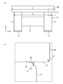
図3(a)は、実施例1に係るコイル部品の外形寸法を説明するための図であり、図3(b)は、図3(a)の領域Aの拡大図である。図3(a)のように、Y軸方向において、板コア30の長さL1とドラムコア10の長さL2とは略同じ長さになっている。なお、略同じ長さとは、製造誤差程度の違いを含むものである。
FIG. 3A is a diagram for explaining the outer dimensions of the coil component according to the first embodiment, and FIG. 3B is an enlarged view of the area A in FIG. 3A. As shown in FIG. 3A, the length L1 of the
図3(b)のように、鍔部14の上面22と板コア30の下面32の角部は、面取りがされていてR形状となっている。鍔部14の上面22の角部に設けられたR形状のR寸法であるR1は、板コア30の下面32の角部に設けられたR形状のR寸法であるR2よりも大きくなっている。なお、R寸法とは、R形状を形成する曲面の半径寸法である。
As shown in FIG. 3B, the corners of the
次に、実施例1に係るコイル部品100の製造方法について説明する。ここでは、ドラムコア10及び板コア30に、磁性材料として透磁率が400〜1000程度のNi−Zn系フェライト材料を用いる場合を例に説明する。まず、Ni−Zn系フェライト材にバインダーを混合し、成形金型を用いて圧縮成形をして、ドラムコア10及び板コア30それぞれの成形体を形成する。そして、成形体を所定の温度で焼結させることで、ドラムコア10と板コア30とを形成する。
Next, a method for manufacturing the
成形体を形成するとき、フェライト材(磁性材料)の充填率をドラムコア10の鍔部14と板コア30とで異ならせることで、図3(b)で説明したような、R寸法の異なるR形状を有する鍔部14と板コア30の形成を容易にできる。また、ドラムコア10の軸部12及び板コア30のフェライト材(磁性材料)の充填率をドラムコア10の鍔部14のフェライト材(磁性材料)の充填率よりも大きくすることで、電気特性を良好に維持しつつ、軸部12及び板コア30の機械的強度を高くでき、コイル部品100の小型化が可能となる。
When forming the molded body, the filling ratio of the ferrite material (magnetic material) is made different between the
なお、必要に応じて、成形体の表面が所望の表面粗さ及び/又は表面うねりとなるように、成形体に対してバレル研磨などの研磨処理を施してもよい。研磨処理は、バレル研磨以外の一般的に知られている研磨方法を用いることもできる。また、自動研磨装置を用いることで、表面粗さ及び/又は表面うねりの制御が容易となる。 If necessary, the molded body may be subjected to polishing treatment such as barrel polishing so that the surface of the molded body has a desired surface roughness and/or surface waviness. For the polishing treatment, a generally known polishing method other than barrel polishing can be used. Further, by using the automatic polishing apparatus, it becomes easy to control the surface roughness and/or the surface waviness.
ドラムコア10及び板コア30を形成した後、鍔部14の所定の位置にAgペーストをローラ転写して熱処理を行い、その上にNiめっき層及びSnめっき層を形成して、電極70を形成する。例えば、Niめっき層とSnめっき層の合計厚さは10μm程度である。
After the
次に、導線52を軸部12の外周に巻回して、周回部54と引出部56を有するコイル50を形成する。このときに、軸部12のJISB0601に規定されている表面粗さRaは、鍔部14の表面粗さRaよりも小さい場合が好ましい。これにより、導線52を軸部12の外周に安定した状態で巻回すことができる。その後、鍔部14の上面22と板コア30の下面32との間に接着剤40を設け、ドラムコア10と板コア30とで接着剤40を押圧しながら硬化させることで、鍔部14の上面22と板コア30の下面32とを接着剤40で接着させる。
Next, the
図4及び図5は、ドラムコアと板コアとを接着させる工程を示す断面図である。図4のように、板コア30の下面32が上側となるように板コア30を冶具90内に収納した後、板コア30の下面32の所定の位置にディスペンサなどを用いて所定量の接着剤40を塗布する。冶具90の内径寸法は、板コア30の外径寸法とほぼ同じになっており、冶具90内に板コア30を収納することで、板コア30は冶具90によって固定される。その後、板コア30の下面32に塗布された接着剤40にドラムコア10の鍔部14の上面22を接触させる。
4 and 5 are cross-sectional views showing a step of adhering the drum core and the plate core. As shown in FIG. 4, after the
接着剤40の塗布量及び塗布位置は、板コア30の下面32に鍔部14の上面22を接触させた際に、接着剤40が鍔部14の上面22の縁から食み出ることなく、且つ、板コア30の下面32と鍔部14の上面22との間に必要十分な量の接着剤40が存在するように調整する。
The application amount and application position of the adhesive 40 are such that the adhesive 40 does not run off from the edge of the
図5のように、ドラムコア10と板コア30を収納する複数の冶具90を重ね、熱プレスにより加重しながら接着剤40を熱硬化させる。加重は、例えば接触面積に対する圧力換算値で0.1MPa〜1MPaとすることができる。硬化温度は、接着剤40のガラス転移温度Tgにより決定される。例えば、ガラス転移温度Tgより高く且つTg+50℃以下の温度で硬化させることができる。接着剤40は加重が掛かりながら硬化するため、ドラムコア10と板コア30の垂直方向の姿勢がずれることなく安定して接着する。また、冶具90内で接着剤40の本硬化を行うことにより、例えば仮硬化後に別装置に移動させて本硬化を行う場合と比較して、移載に伴う製品の損傷を抑制することができる。このように、ドラムコア10と板コア30の接着時のハンドリングと接着剤40の位置決めとを冶具90内で行うことにより、ハンドリング回数を少なくすることができる。また、ドラムコア10と板コア30の接着を冶具90内で行うことで、例えば小型で軽量なドラムコア10を用いる場合でも、接着剤40の硬化時の膨張又は収縮などの挙動による位置移動を抑えることができる。
As shown in FIG. 5, a plurality of
また、板コア30の下面32の表面に接着剤40を塗布し、接着剤40の上にドラムコア10を重ね、ドラムコア10側から板コア30に向って押圧しながら接着剤40を硬化させることで、板コア30の表面へ接着剤40は濡れ広がり、接着剤40の厚みを均一にでき、また、これに合わせて厚みを薄くすることができる。また、接着剤40を表面粗さの大きい鍔部14側から押し込むことで、接着剤40中のフィラー44は動き易く、鍔部14の上面22の凹部に入り込み易くなる。結果、鍔部14の上面22と板コア30の下面32とが直接接触するようになるまで、2つのコアを近づけることができる。つまり、接着剤40の影響を受けず、2つのコア間の距離を安定して得ることができ、高く、安定したインダクタンス特性を得ることができる。
Further, by applying the adhesive 40 to the surface of the
冶具90の下面には柔軟性を有するシート92が備わっていてもよい。シート92として、例えば合成ゴム又はシリコンゴム製のシートを用いることができる。冶具90の下面にシート92が備わることで、熱プレスによる加重が加えられた場合でもドラムコア10に破損が生じることを抑制できる。
A
ここで、比較例に係るコイル部品について説明する。比較例のコイル部品は、実施例1と同様にコモンモードチョークコイルである。図6(a)は、比較例に係るコイル部品の断面図、図6(b)は、図6(a)の領域Aの拡大図である。なお、図6(a)では、図の明瞭化のために、コイル50の図示は省略している。図6(a)及び図6(b)のように、比較例では、ドラムコア110の鍔部114の上面122と板コア130の下面132とが接着剤40で接着されている。鍔部114の上面122の表面粗さ及び板コア130の下面132の表面粗さは、フィラー44の平均粒径よりも小さくなっている。このため、鍔部114の上面122と板コア130の下面132とが接触又は非常に薄い樹脂42を挟んで対向する近接部46は形成されていない。したがって、接着剤40の接着条件によっては、鍔部114の上面122と板コア130の下面132との間に介在する接着剤40が厚くなったり又は薄くなったりすることが生じる。接着剤40が薄くなると、鍔部114と板コア130の接着強度が低下してしまう。
Here, a coil component according to a comparative example will be described. The coil component of the comparative example is a common mode choke coil as in the first embodiment. 6A is a cross-sectional view of a coil component according to a comparative example, and FIG. 6B is an enlarged view of a region A of FIG. 6A. In FIG. 6A, the
一方、実施例1によれば、図2(b)のように、鍔部14の接着剤40を介して板コア30に接着する上面22の表面粗さが、接着剤40に含まれるフィラー44の平均粒径よりも大きい。このため、フィラー44は鍔部14の上面22の凹部に入り込むことができ、鍔部14の上面22と板コア30の下面32とが直接接触する又は薄い樹脂42を挟んで対向する近接部46が形成される。近接部46が形成されることで、鍔部14の上面22と板コア30の下面32との間の領域のうちの近接部46以外の領域に、ある程度の厚みを有する接着剤40を形成することができる。よって、ドラムコア10(鍔部14)と板コア30との接着強度を良好にすることができる。
On the other hand, according to the first embodiment, as shown in FIG. 2B, the surface roughness of the
また、比較例では、接着剤40の接着条件によっては接着剤40が厚くなり、鍔部14と板コア30との間隔が広くなることがある。この場合、磁気ギャップが大きくなり、インダクタンス特性の低下が生じてしまう。一方、実施例1では、鍔部14と板コア30との間隔が近接部46によって規定されるようになるため、鍔部14と板コア30との間隔が狭くなる。よって、磁気ギャップを小さくすることができ、良好なインダクタンス特性を得ることができる。
In addition, in the comparative example, the adhesive 40 may become thick depending on the bonding condition of the adhesive 40, and the gap between the
このように、実施例1によれば、良好な接着強度と良好なインダクタンス特性の両立を図ることができる。 Thus, according to the first embodiment, both good adhesive strength and good inductance characteristics can be achieved.
また、実施例1によれば、鍔部14の上面22と板コア30の下面32の両方で、表面粗さがフィラー44の平均粒径よりも大きい。この場合、鍔部14と板コア30の間に介在する接着剤40の密着性を高くでき、鍔部14と板コア30との接着強度を高くできる。
Further, according to the first embodiment, the surface roughness of both the
鍔部14と板コア30とは、好適には、接着剤40を間に挟む上面22及び下面32の一部で直接接触している。すなわち、鍔部14の上面22と板コア30の下面32とは、好適には、近接部46で直接接触している。これにより、鍔部14の上面22と板コア30の下面32との間隔を安定した大きさにでき、ある程度の厚みを有する接着剤40を鍔部14の上面22と板コア30の下面32との間に容易に形成することができる。よって、鍔部14と板コア30との接着強度を良好にすることができる。また、鍔部14と板コア30との間隔が安定するため、インダクタンス特性、又は他の電気特性についても安定して良好な特性を得ることができる。
The
板コア30の下面32の表面うねりは、好適には、鍔部14の上面22の表面うねりよりも小さい。板コア30の下面32の表面うねりが小さくなることで、鍔部14と板コア30との間隔が狭くなるため、磁気ギャップを小さくすることができる。磁気ギャップを小さくする点から、鍔部14の上面22の表面うねりWaは、80μm以下、又は60μm以下とする。この範囲とすることで、インダクタンス特性の低下を抑制できる。また、表面うねりにより、鍔部14と板コア30との近接部46の数を少なくできる。つまり、近接部46の数が少なくなると共に、直接接触する部分が確実に設けられるようになり、より磁気ギャップを小さく、また磁気ギャップの安定化につながる。
The surface waviness of the
図7は、鍔部の表面うねりを説明する図である。図7のように、鍔部14のX軸方向(幅方向)において、鍔部14の上面22の中央部分がくぼむ方向に湾曲させるうねりとする。例えば、鍔部14の幅方向の中央線A−Aから外側にそれぞれd1、d2部分に突起が設けられ、この突起部分が近接部46となるようにする。鍔部14の幅に対する距離d1、d2の合計が半分以上となるようにする。このようにすれば、近接部46が鍔部14の幅方向の中央から離れたところに設けられ、更に接着時の安定性を高めることができ、接着強度を高めることとなる。
FIG. 7: is a figure explaining the surface waviness of a collar part. As shown in FIG. 7, in the X-axis direction (width direction) of the
また、磁気ギャップを小さくする点から、接着剤40の厚さは25μm以下が好ましく、20μm以下がより好ましく、15μm以下が更に好ましい。鍔部14の上面22の表面粗さがフィラー44の平均粒径よりも大きいことで近接部46が形成されるため、接着剤40の厚さを安定して25μm以下とすることができる。また、接着剤40の厚さが薄くなることで、接着剤40の使用量が少なくなるため、所定領域からの接着剤40の食み出し量を抑制できる。
From the viewpoint of reducing the magnetic gap, the thickness of the adhesive 40 is preferably 25 μm or less, more preferably 20 μm or less, and further preferably 15 μm or less. Since the surface roughness of the
図1のように、好適には、鍔部14と板コア30との間に設けられた接着剤40は、コイル50を形成する導線52から離れている。これにより、接着剤40が導線52に影響を及ぼすことを抑制できる。例えば、接着剤40の硬化時における体積収縮に起因する導線52への応力、接着剤40を構成する成分と導線52の絶縁被膜成分との化学反応、又は接着剤40による導線52間の浮遊容量の変化などを抑えることができる。
As shown in FIG. 1, preferably, the adhesive 40 provided between the
板コア30及びドラムコア10を構成する軸部12の磁性材料の充填率は、好適には、ドラムコア10を構成する鍔部14の磁性材料の充填率よりも大きい。これにより、電気特性を良好にしつつ、板コア30及び軸部12の機械的強度を高めることができるため、コイル部品100の小型化が可能となる。
The filling rate of the magnetic material of the
実施例1のコイル部品100の外形寸法は、一例として、長さ(Y軸方向の長さ)3.2mm、幅(X軸方向の長さ)2.5mm、高さ(Z軸方向の長さ)2.5mmである。ドラムコア10の外形寸法は、一例として、長さ2.9mm、幅2.5mm、高さ2.1mmである。ドラムコア10の軸部12の外形寸法は、一例として、幅1.1mm、高さ0.8mmであり、鍔部14の厚さ(Y軸方向の長さ)は、一例として、0.3mmである。板コア30の外形寸法は、一例として、長さ3.2mm、幅2.5mm、高さ0.4mmである。なお、板コア30の長さ(Y軸方向の長さ)は、3.2mm以下とすることが可能であり、2.5mm、1.6mmとすることもできる。
The external dimensions of the
図8(a)は、実施例2に係るコイル部品の断面図、図8(b)は、図8(a)の領域Aの拡大図である。なお、図8(a)では、図の明瞭化のために、コイル50の図示は省略している。図8(a)及び図8(b)のように、実施例2では、鍔部14の上面22の表面粗さはフィラー44の平均粒径よりも大きいが、板コア30aの下面32の表面粗さは、鍔部14の上面22の表面粗さよりも小さく、フィラー44の平均粒径よりも小さい。例えば、鍔部14の上面22の表面粗さRzはフィラー44の平均粒径よりも大きく、板コア30aの下面32の表面粗さRzは、鍔部14の上面22の表面粗さRzより小さく、フィラー44の平均粒径よりも小さい。例えば、ドラムコア10に用いる磁性材料の粒径を板コア30aに用いる磁性材料の粒径よりも大きくしたり、又は、ドラムコア10での磁性材料の充填率を板コア30aでの磁性材料の充填率より低くしたりすることで、鍔部14の上面22の表面粗さを大きくでき、板コア30aの下面32の表面粗さを小さくできる。また、ドラムコア10に対して例えば大きなメディアを用いたバレル加工などの加工処理を施すことで、鍔部14の上面22の表面粗さを大きくすることもできる。その他の構成は、実施例1と同じであるため図示及び説明を省略する。
8A is a cross-sectional view of the coil component according to the second embodiment, and FIG. 8B is an enlarged view of a region A of FIG. 8A. In FIG. 8A, the
鍔部14の上面22の表面粗さRzは、例えば10μm以上であり、20μm以上でもよい。板コア30aの下面32の表面粗さRzは、例えば1μm以上であり、10μm以上でもよい。鍔部14の上面22の表面粗さRz及び板コア30aの下面32の表面粗さRzは、例えば30μm以下である。一例として、ドラムコア10及び板コア30aがNi−Zn系のフェライト材料で形成されている場合、鍔部14の上面22の表面粗さRzは15μm程度、板コア30aの下面32の表面粗さRzは1μm程度である。このように、ドラムコア10及び板コア30aの場合において、板コア30aの下面32の表面粗さRzは、鍔部14の上面22の表面粗さRzより小さくなるようにしてもよい。
The surface roughness Rz of the
実施例2によれば、板コア30aの下面32の表面粗さは、鍔部14の上面22の表面粗さよりも小さく、フィラー44の平均粒径よりも小さい。これにより、鍔部14と板コア30aとの間に生じる面積を小さくでき、磁気ギャップを更に小さくすることができる。
According to the second embodiment, the surface roughness of the
なお、ドラムコア10と板コア30aの表面粗さの関係が反対の場合でもよい。すなわち、板コアの下面の表面粗さはフィラー44の平均粒径よりも大きく、ドラムコアを構成する鍔部の上面の表面粗さは、板コアの下面の表面粗さよりも小さく、フィラー44の平均粒径よりも小さい場合でもよい。この場合、板コアは、特許請求の範囲における第1基体部に相当し、ドラムコアは、特許請求の範囲における第2基体部に相当する。
The surface roughness relationship between the
実施例3のコイル部品は、板コア30bの長さが実施例1の板コア30と異なる点以外は実施例1のコイル部品100と同じであるため、板コア30bの長さ以外についての図示及び説明を省略する。図9(a)は、実施例3に係るコイル部品の外形寸法を説明するための図、図9(b)は、図9(a)の領域Aの拡大図である。図9(a)のように、Y軸方向において、板コア30bの長さL1は、ドラムコア10の長さL2よりも長くなっている。例えば、板コア30bの長さL1は、ドラムコア10の長さL2よりも0.1mm〜0.2mm程度長くなっている。図9(b)のように、鍔部14の上面22と板コア30bの下面32の角部は、実施例1と同じく、面取りがされてR形状となっている。板コア30bとドラムコア10の長さの差(L1−L2)は、鍔部14の上面22の角部に設けられたR形状のR寸法であるR1よりも大きくなっている。
The coil component of the third embodiment is the same as the
実施例3によれば、Y軸方向(コイル軸方向)における板コア30bの長さL1は、Y軸方向(コイル軸方向)におけるドラムコア10の長さL2よりも長い。これにより、ドラムコア10と板コア30bとの接着に伴う位置ずれを吸収することができ、接着面積の変化が抑えられるため、電気特性の安定性を得ることができる。なお、図9(a)では、Y軸方向における板コア30bとドラムコア10の長さについて説明したが、X軸方向における板コア30bとドラムコア10の長さについても同様の関係になっていることが好ましい。すなわち、X軸方向における板コア30bの長さは、X軸方向におけるドラムコア10の長さよりも長い場合が好ましい。
According to the third embodiment, the length L1 of the
また、鍔部14の上面22における角部にはR形状が形成されている。そして、Y軸方向(コイル軸方向)における板コア30bの長さL1とドラムコア10の長さL2との差(L1−L2)は、鍔部14の上面22の角部のR形状におけるR寸法であるR1よりも大きい。これにより、鍔部14の上面22の角部のR形状の部分での接着剤40は、鍔部14の上面22の角部のR形状を設けることにより生じる空間に留まろうとし、接着剤40の濡れ広がりを抑制できる。また、板コア30bの長さが大きい分、接着剤40の長さ方向へのはみ出しを防ぐことができる。
In addition, an R shape is formed at a corner portion on the
実施例1から実施例3では、コイル部品の例として、ドラムコア10と板コア30を有するコモンモードチョークコイルの場合を例に示したが、この場合に限られず、他の用途として、インダクタ、フィルタ、又はトランスなどの場合でもよい。実施例4では、コイル部品として、E型コアとI型コアを有するインダクタ素子の場合を説明する。
In the first to third embodiments, the case of the common mode choke coil having the
図10(a)は、E型コアとI型コアを示す斜視図、図10(b)は、E型コアとI型コアが接着剤で接着された状態の断面図である。図10(a)及び図10(b)のように、E型コア80とI型コア82が接着剤40で接着されている。E型コア80とI型コア82は、同じ磁性材料で形成されていてもよいし、異なる磁性材料で形成されていてもよい。E型コア80とI型コア82が接着した後の外形寸法は、一例として、長さ5.0mm、幅4.0mm、高さ2.5mmである。なお、I型コア82は、特許請求の範囲における第1基体部に相当し、E型コア80は、特許請求の範囲における第2基体部に相当する。
FIG. 10A is a perspective view showing an E-type core and an I-type core, and FIG. 10B is a cross-sectional view showing a state in which the E-type core and the I-type core are bonded with an adhesive. As shown in FIGS. 10A and 10B, the
I型コア82の接着剤40を介してE型コア80に接着する面の表面粗さは、実施例1のドラムコア10と同様の関係にあり、接着剤40に含まれるフィラー44の平均粒径よりも大きい。E型コア80の接着剤40を介してI型コア82に接着する面の表面粗さは、I型コア82の接着剤40を介してE型コア80に接着する面の表面粗さよりも小さくてもよい。また、E型コア80の接着剤40を介してI型コア82に接着する面の表面粗さは、フィラー44の平均粒径よりも大きくてもよい。例えば、I型コア82に用いる磁性材料の粒径をE型コア80に用いる磁性材料の粒径よりも大きくしたり、又は、I型コア82での磁性材料の充填率をE型コア80での磁性材料の充填率より低くしたりすることで、I型コア82の表面粗さを大きくでき、E型コア80の表面粗さを小さくできる。また、I型コア82に対して例えば大きなメディアを用いたバレル加工などの加工処理を施すことで、I型コア82の表面粗さを大きくすることもできる。
The surface roughness of the surface of the I-shaped
I型コア82の表面粗さRzは例えば20μm以上であり、E型コア80の表面粗さRzは例えば10μm以上である。E型コア80及びI型コア82の表面粗さRzは、例えば50μm以下である。表面粗さRzを50μm以下に抑えることで、E型コア80及びI型コア82の表面へ接着剤40が濡れ広がり易くなる。このため、接着剤40の厚みを均一にでき、また合わせて厚みを薄くすることができる。例えば、接着剤40を塗布時の厚みとして、厚みの大きな部分で50μm以下とすることができる。また、E型コア80及びI型コア82の機械的強度を確保する点から、表面粗さRzを30μm以下としてもよい。一例として、E型コア80及びI型コア82がFe−Si−Cr系の合金磁性材料で形成されている場合、I型コア82の表面粗さRzは20μm程度、E型コア80の表面粗さRzは10μm程度である。なお、表面粗さの調整は、例えば、E型コア80及びI型コア82の製造条件によって行い、E型コア80及びI型コア82の表面粗さの差が、50%以内であれば同じとみなし、50%を超える場合を異なるとする。
The surface roughness Rz of the I-shaped
E型コア80及びI型コア82の磁性材料として、例えばFe及びSiを含む合金磁性材料を用いることができる。磁性材料の透磁率(μ)は30〜60であることが好ましい。E型コア80及びI型コア82の製造方法は、まず、Fe−Si−Cr系の合金磁性粒子にバインダーを混合し、成形金型を用いて圧縮成形して、E型コア80及びI型コア82とするため、それぞれの成形体を形成する。このときに、それぞれの成形体で、磁性材料の充填率を異ならせてもよい。例えば、E型コア80の成形体の磁性材料の充填率をI型コア82の成形体の磁性材料の充填率よりも大きくすることが好ましい。これにより、破損し易いE型コア80の機械的強度を高くでき、インダクタ素子の小型化が可能となる。その後、成形体を熱処理して樹脂を硬化させるか、または所定の温度で合金磁性粒子の表面を酸化させ、絶縁膜による合金磁性粒子同士を結合させることで、E型コア80とI型コア82を形成する。
As the magnetic material of the
E型コア80とI型コア82を形成した後、E型コア80及びI型コア82の少なくとも一方に電極を形成する。次に、E型コア80の空間に導線を用いてコイルを形成する。その後、E型コア80とI型コア82とを接着剤40で接着させる。E型コア80とI型コア82の接着部分は、実施例1の図2と同様の形状となる。
After forming the
このように、E型コア80とI型コア82を接着剤40で接着させる場合でも、I型コア82の接着剤40を介してE型コア80に接着する面の表面粗さがフィラー44の平均粒径よりも大きいことで、実施例1と同様に、E型コア80とI型コア82の接着強度を良好にすることができる。また、実施例1と同様に、E型コア80とI型コア82との間隔を狭くできるため、インダクタンス特性を良好にすることができる。
As described above, even when the
なお、E型コア80とI型コア82の表面粗さの関係が反対の場合でもよい。すなわち、E型コア80の接着剤40に接する面の表面粗さはフィラー44の平均粒径よりも大きく、I型コア82の接着剤40に接する面の表面粗さは、E型コア80の接着剤40に接する面の表面粗さよりも小さく、例えばフィラー44の平均粒径よりも小さい場合でもよい。この場合、E型コア80は、特許請求の範囲におけり第1基体部に相当し、I型コア82は、特許請求の範囲における第2基体部に相当する。更には、基体部の数は2つより多い場合でもよく、例えば、2つのE型コア80とI型コア82を用いることでもよく、特に基体部の数が制限されることはない。また、実施例1についても同様であり、2つ以上の板コア30とドラムコア10を用いることでもよい。
The
図10は、実施例5に係る電子機器の断面図である。図10のように、実施例5の電子機器500は、回路基板84と回路基板84に実装された実施例1のコイル部品100と、を備える。コイル部品100は、電極70が半田88によって回路基板84の電極86に接合されることで、回路基板84に実装されている。
FIG. 10 is a sectional view of the electronic device according to the fifth embodiment. As shown in FIG. 10, an
実施例5の電子機器500によれば、回路基板84に実施例1のコイル部品100が実装されている。これにより、ドラムコア10と板コア30の接着強度が向上した衝撃耐性の高いコイル部品100を備える電子機器500を得ることができる。なお、実施例5では、回路基板84に実施例1のコイル部品100が実装されている場合を例に示したが、実施例2から実施例4のコイル部品が実装される場合でもよい。
According to the
以上、本発明の実施例について詳述したが、本発明はかかる特定の実施例に限定されるものではなく、特許請求の範囲に記載された本発明の要旨の範囲内において、種々の変形・変更が可能である。 Although the embodiments of the present invention have been described in detail above, the present invention is not limited to these specific embodiments, and various modifications and alterations are possible within the scope of the gist of the present invention described in the claims. It can be changed.
10 ドラムコア
12 軸部
14 鍔部
20 下面
22 上面
30、30a、30b 板コア
32 下面
40 接着剤
42 樹脂
44 フィラー
46 近接部
50 コイル
52 導線
54 周回部
56 引出部
70 電極
80 E型コア
82 I型コア
84 回路基板
86 電極
88 半田
100 コイル部品
500 電子機器
10
Claims (10)
有機材料と、前記磁性材料とは異なる無機粒子であるフィラーと、を含有し、前記第1基体部と前記第2基体部を接着させる接着剤と、
絶縁被膜を有する導体で形成されたコイルと、
前記コイルに電気的に接続された電極と、を備え、
前記第1基体部の前記接着剤を介して前記第2基体部に接着する面の表面粗さは、前記フィラーの平均粒径よりも大きい、コイル部品。 A first base portion and a second base portion formed by including a magnetic material;
And an organic material, an adhesive different from the filler are inorganic particles, containing, adhering the second base portion and the first base portion and the magnetic material,
A coil formed of a conductor having an insulating coating,
An electrode electrically connected to the coil,
The coil component, wherein the surface roughness of the surface of the first base portion that is bonded to the second base portion via the adhesive is larger than the average particle diameter of the filler.
前記第2基体部は、前記軸部の両端に設けられた2つの前記鍔部に接着した板状の板コアであり、
前記接着剤は、前記鍔部と前記板コアとを接着する、請求項1から4のいずれか一項記載のコイル部品。 The first base portion is a drum core having a shaft portion around which the conductor is wound and flange portions provided at both ends of the shaft portion,
The second base portion is a plate-like plate core adhered to the two flange portions provided at both ends of the shaft portion,
The coil component according to any one of claims 1 to 4 , wherein the adhesive bonds the flange portion to the plate core.
前記コイル軸方向における前記板コアの長さと前記ドラムコアの長さとの差は、前記鍔部の前記R形状におけるR寸法よりも大きい、請求項6記載のコイル部品。 An R shape is formed at a corner portion of a surface of the collar portion that is bonded to the plate core via the adhesive.
The coil component according to claim 6 , wherein a difference between a length of the plate core and a length of the drum core in the coil axial direction is larger than an R dimension of the flange portion in the R shape.
前記コイル部品が実装された回路基板と、を備える、電子機器。 A coil component according to any one of claims 1 to 9 ,
An electronic device comprising: a circuit board on which the coil component is mounted.
Priority Applications (3)
| Application Number | Priority Date | Filing Date | Title |
|---|---|---|---|
| JP2018185572A JP6730397B2 (en) | 2018-09-28 | 2018-09-28 | Coil parts and electronic equipment |
| US16/572,288 US11670442B2 (en) | 2018-09-28 | 2019-09-16 | Coil component and electronic device |
| CN201910899135.9A CN110970204B (en) | 2018-09-28 | 2019-09-23 | Coil components and electronic devices |
Applications Claiming Priority (1)
| Application Number | Priority Date | Filing Date | Title |
|---|---|---|---|
| JP2018185572A JP6730397B2 (en) | 2018-09-28 | 2018-09-28 | Coil parts and electronic equipment |
Publications (2)
| Publication Number | Publication Date |
|---|---|
| JP2020057656A JP2020057656A (en) | 2020-04-09 |
| JP6730397B2 true JP6730397B2 (en) | 2020-07-29 |
Family
ID=69946029
Family Applications (1)
| Application Number | Title | Priority Date | Filing Date |
|---|---|---|---|
| JP2018185572A Active JP6730397B2 (en) | 2018-09-28 | 2018-09-28 | Coil parts and electronic equipment |
Country Status (3)
| Country | Link |
|---|---|
| US (1) | US11670442B2 (en) |
| JP (1) | JP6730397B2 (en) |
| CN (1) | CN110970204B (en) |
Families Citing this family (16)
| Publication number | Priority date | Publication date | Assignee | Title |
|---|---|---|---|---|
| JP6638711B2 (en) * | 2017-09-21 | 2020-01-29 | 株式会社村田製作所 | Coil parts |
| JP1638080S (en) * | 2018-08-22 | 2019-08-05 | ||
| USD918835S1 (en) * | 2018-08-22 | 2021-05-11 | Tdk Corporation | Coil component |
| JP6943235B2 (en) * | 2018-12-24 | 2021-09-29 | 株式会社村田製作所 | Coil parts |
| JP2020136391A (en) * | 2019-02-15 | 2020-08-31 | 株式会社村田製作所 | Winding inductor parts |
| JP7159901B2 (en) * | 2019-02-16 | 2022-10-25 | 株式会社村田製作所 | Differential mode choke coil component and circuit with same |
| JP7557931B2 (en) * | 2019-08-30 | 2024-09-30 | Tdk株式会社 | Coil parts |
| WO2021092106A1 (en) * | 2019-11-07 | 2021-05-14 | Hyperloop Technologies, Inc. | A force-producing electromagnetic machine |
| JP7151740B2 (en) * | 2020-03-12 | 2022-10-12 | 株式会社村田製作所 | Winding core and coil parts |
| JP7566238B2 (en) * | 2020-08-19 | 2024-10-15 | 株式会社オートネットワーク技術研究所 | Reactor, converter, and power conversion device |
| JP7609591B2 (en) | 2020-09-25 | 2025-01-07 | 株式会社村田製作所 | Coil parts |
| JP7562360B2 (en) * | 2020-10-06 | 2024-10-07 | 株式会社村田製作所 | Coil parts |
| JP2022161282A (en) | 2021-04-08 | 2022-10-21 | 株式会社村田製作所 | Coil component |
| JP7501462B2 (en) | 2021-07-13 | 2024-06-18 | 株式会社村田製作所 | Coil parts |
| JP7491288B2 (en) * | 2021-10-28 | 2024-05-28 | 株式会社村田製作所 | Coil parts |
| US20240212925A1 (en) * | 2022-12-21 | 2024-06-27 | Tai-Tech Advanced Electronics Co., Ltd. | Inductor |
Family Cites Families (31)
| Publication number | Priority date | Publication date | Assignee | Title |
|---|---|---|---|---|
| JPH04105520U (en) * | 1991-02-20 | 1992-09-10 | 松下電器産業株式会社 | transformer |
| JP3195585B2 (en) | 1998-10-27 | 2001-08-06 | ティーディーケイ株式会社 | Surface mount self-induction type inductance component |
| JP3710042B2 (en) * | 1999-09-20 | 2005-10-26 | Tdk株式会社 | Common mode filter |
| JP2003168611A (en) * | 2001-09-18 | 2003-06-13 | Murata Mfg Co Ltd | High-frequency common mode choke coil |
| US7567163B2 (en) | 2004-08-31 | 2009-07-28 | Pulse Engineering, Inc. | Precision inductive devices and methods |
| JP2007142931A (en) | 2005-11-21 | 2007-06-07 | Murata Mfg Co Ltd | Noise filter |
| WO2007060961A1 (en) | 2005-11-22 | 2007-05-31 | Murata Manufacturing Co., Ltd. | Winding type coil |
| KR20070074059A (en) * | 2006-01-06 | 2007-07-12 | 삼성전자주식회사 | Magnetic core and inductors and transformers comprising the same |
| JP2009224649A (en) | 2008-03-18 | 2009-10-01 | Tdk Corp | Surface mounting type pulse transformer and common-mode choke-coil integrated surface mounting type pulse transformer and modular jack part using these pulse transformer |
| JP2009259991A (en) * | 2008-04-16 | 2009-11-05 | Oki Power Tech Co Ltd | Magnetic device and power unit using the same |
| JP2009302321A (en) * | 2008-06-13 | 2009-12-24 | Tdk Corp | Coil component and method of manufacturing the same |
| JP4924689B2 (en) * | 2008-10-27 | 2012-04-25 | 日立金属株式会社 | Ferrite grinding body, ferrite core, manufacturing method, grinding method and apparatus |
| WO2011027559A1 (en) * | 2009-09-03 | 2011-03-10 | パナソニック株式会社 | Coil part and method for producing same |
| CN102074333B (en) * | 2009-11-24 | 2013-06-05 | 台达电子工业股份有限公司 | Mixed material magnetic core group, magnetic element and manufacturing method |
| US8975993B2 (en) * | 2010-11-26 | 2015-03-10 | Tdk Corporation | Transformer |
| JP5201199B2 (en) | 2010-12-02 | 2013-06-05 | Tdk株式会社 | Step-up transformer |
| JP6405609B2 (en) * | 2012-10-03 | 2018-10-17 | Tdk株式会社 | Inductor element and manufacturing method thereof |
| JP5811139B2 (en) | 2012-10-16 | 2015-11-11 | Tdk株式会社 | Coil parts |
| JP5796603B2 (en) * | 2012-10-16 | 2015-10-21 | Tdk株式会社 | Coil parts |
| JP2015032643A (en) * | 2013-07-31 | 2015-02-16 | 太陽誘電株式会社 | Electronic component |
| JP6264805B2 (en) * | 2013-09-25 | 2018-01-24 | Tdk株式会社 | Pulse transformer |
| DE102014103324B4 (en) | 2014-03-12 | 2022-11-24 | Tdk Electronics Ag | Inductive component and method for producing an inductive component |
| JP6672614B2 (en) * | 2014-07-17 | 2020-03-25 | Tdk株式会社 | Coil parts |
| JP6316136B2 (en) | 2014-08-01 | 2018-04-25 | 太陽誘電株式会社 | Coil component and electronic device including the same |
| JP6445396B2 (en) * | 2015-06-09 | 2018-12-26 | 太陽誘電株式会社 | Common mode filter |
| JP6399010B2 (en) * | 2016-02-09 | 2018-10-03 | 株式会社村田製作所 | Coil parts |
| WO2017170492A1 (en) * | 2016-03-30 | 2017-10-05 | 積水化学工業株式会社 | Inductor adhesive and inductor |
| JP6830340B2 (en) * | 2016-11-08 | 2021-02-17 | 株式会社村田製作所 | Coil parts |
| JP6577970B2 (en) | 2017-03-31 | 2019-09-18 | 太陽誘電株式会社 | Common mode choke coil, manufacturing method thereof, circuit board. |
| US11837396B2 (en) * | 2018-02-05 | 2023-12-05 | Murata Manufacturing Co., Ltd. | Common-mode choke coil |
| JP7076234B2 (en) * | 2018-03-14 | 2022-05-27 | 株式会社村田製作所 | Coil parts and their manufacturing methods |
-
2018
- 2018-09-28 JP JP2018185572A patent/JP6730397B2/en active Active
-
2019
- 2019-09-16 US US16/572,288 patent/US11670442B2/en active Active
- 2019-09-23 CN CN201910899135.9A patent/CN110970204B/en active Active
Also Published As
| Publication number | Publication date |
|---|---|
| US20200105451A1 (en) | 2020-04-02 |
| JP2020057656A (en) | 2020-04-09 |
| US11670442B2 (en) | 2023-06-06 |
| CN110970204A (en) | 2020-04-07 |
| CN110970204B (en) | 2024-11-15 |
Similar Documents
| Publication | Publication Date | Title |
|---|---|---|
| JP6730397B2 (en) | Coil parts and electronic equipment | |
| JP6577970B2 (en) | Common mode choke coil, manufacturing method thereof, circuit board. | |
| CN105575621B (en) | Coil assembly and coil assembly | |
| CN100403462C (en) | Thin transformer and manufacturing method thereof | |
| JP5885121B2 (en) | Antenna coil parts | |
| TWI719285B (en) | Coil parts | |
| JP2008053670A (en) | Inductor using dram-type core and manufacturing method therefor | |
| US10366819B2 (en) | Coil component and method of manufacturing the same | |
| JP2007504673A (en) | Fractional winding transformer with ferrite polymer core | |
| US20180358157A1 (en) | Magnetic core component and gap control method thereof | |
| JP2009302386A (en) | Surface-mounted inductor | |
| TWI679661B (en) | Coil type coil parts | |
| CN108028119A (en) | Magnetic element | |
| JP2004040001A (en) | Coil component and circuit device | |
| CN1655298B (en) | Surface mount type coil part and manufacturing method thereof | |
| US11164695B2 (en) | Inductor component | |
| KR101310360B1 (en) | Winding-type chip inductor for power and manufacturing method thereof | |
| JP6955382B2 (en) | Laminated coil | |
| US11515079B2 (en) | Laminated coil | |
| JP2005129910A (en) | Module incorporating capacitor, manufacturing method therefor, and capacitor used therefor | |
| JP2009016563A (en) | Wire-wound electronic component, and manufacturing method of wire-wound electronic component | |
| CN112582156A (en) | Coil component, circuit board, and electronic apparatus | |
| JP2019129294A (en) | Coil component of winding type | |
| WO2024253007A1 (en) | Inductor and method for manufacturing inductor | |
| JP2023098147A (en) | Coil component manufacturing method |
Legal Events
| Date | Code | Title | Description |
|---|---|---|---|
| A621 | Written request for application examination |
Free format text: JAPANESE INTERMEDIATE CODE: A621 Effective date: 20190710 |
|
| A131 | Notification of reasons for refusal |
Free format text: JAPANESE INTERMEDIATE CODE: A131 Effective date: 20191126 |
|
| A521 | Request for written amendment filed |
Free format text: JAPANESE INTERMEDIATE CODE: A523 Effective date: 20200122 |
|
| TRDD | Decision of grant or rejection written | ||
| A01 | Written decision to grant a patent or to grant a registration (utility model) |
Free format text: JAPANESE INTERMEDIATE CODE: A01 Effective date: 20200616 |
|
| A61 | First payment of annual fees (during grant procedure) |
Free format text: JAPANESE INTERMEDIATE CODE: A61 Effective date: 20200702 |
|
| R150 | Certificate of patent or registration of utility model |
Ref document number: 6730397 Country of ref document: JP Free format text: JAPANESE INTERMEDIATE CODE: R150 |
|
| R250 | Receipt of annual fees |
Free format text: JAPANESE INTERMEDIATE CODE: R250 |
|
| R250 | Receipt of annual fees |
Free format text: JAPANESE INTERMEDIATE CODE: R250 |
|
| R250 | Receipt of annual fees |
Free format text: JAPANESE INTERMEDIATE CODE: R250 |