JP6729146B2 - Obstacle detection device - Google Patents
Obstacle detection device Download PDFInfo
- Publication number
- JP6729146B2 JP6729146B2 JP2016153011A JP2016153011A JP6729146B2 JP 6729146 B2 JP6729146 B2 JP 6729146B2 JP 2016153011 A JP2016153011 A JP 2016153011A JP 2016153011 A JP2016153011 A JP 2016153011A JP 6729146 B2 JP6729146 B2 JP 6729146B2
- Authority
- JP
- Japan
- Prior art keywords
- obstacle
- lower traveling
- monitoring area
- construction machine
- monitoring
- Prior art date
- Legal status (The legal status is an assumption and is not a legal conclusion. Google has not performed a legal analysis and makes no representation as to the accuracy of the status listed.)
- Active
Links
Images


Classifications
-
- G—PHYSICS
- G01—MEASURING; TESTING
- G01S—RADIO DIRECTION-FINDING; RADIO NAVIGATION; DETERMINING DISTANCE OR VELOCITY BY USE OF RADIO WAVES; LOCATING OR PRESENCE-DETECTING BY USE OF THE REFLECTION OR RERADIATION OF RADIO WAVES; ANALOGOUS ARRANGEMENTS USING OTHER WAVES
- G01S17/00—Systems using the reflection or reradiation of electromagnetic waves other than radio waves, e.g. lidar systems
- G01S17/88—Lidar systems specially adapted for specific applications
- G01S17/93—Lidar systems specially adapted for specific applications for anti-collision purposes
- G01S17/931—Lidar systems specially adapted for specific applications for anti-collision purposes of land vehicles
-
- E—FIXED CONSTRUCTIONS
- E02—HYDRAULIC ENGINEERING; FOUNDATIONS; SOIL SHIFTING
- E02F—DREDGING; SOIL-SHIFTING
- E02F9/00—Component parts of dredgers or soil-shifting machines, not restricted to one of the kinds covered by groups E02F3/00 - E02F7/00
- E02F9/24—Safety devices, e.g. for preventing overload
-
- B—PERFORMING OPERATIONS; TRANSPORTING
- B66—HOISTING; LIFTING; HAULING
- B66C—CRANES; LOAD-ENGAGING ELEMENTS OR DEVICES FOR CRANES, CAPSTANS, WINCHES, OR TACKLES
- B66C23/00—Cranes comprising essentially a beam, boom, or triangular structure acting as a cantilever and mounted for translatory of swinging movements in vertical or horizontal planes or a combination of such movements, e.g. jib-cranes, derricks, tower cranes
- B66C23/88—Safety gear
-
- E—FIXED CONSTRUCTIONS
- E02—HYDRAULIC ENGINEERING; FOUNDATIONS; SOIL SHIFTING
- E02F—DREDGING; SOIL-SHIFTING
- E02F3/00—Dredgers; Soil-shifting machines
- E02F3/04—Dredgers; Soil-shifting machines mechanically-driven
- E02F3/28—Dredgers; Soil-shifting machines mechanically-driven with digging tools mounted on a dipper- or bucket-arm, i.e. there is either one arm or a pair of arms, e.g. dippers, buckets
- E02F3/36—Component parts
- E02F3/42—Drives for dippers, buckets, dipper-arms or bucket-arms
- E02F3/43—Control of dipper or bucket position; Control of sequence of drive operations
-
- E—FIXED CONSTRUCTIONS
- E02—HYDRAULIC ENGINEERING; FOUNDATIONS; SOIL SHIFTING
- E02F—DREDGING; SOIL-SHIFTING
- E02F9/00—Component parts of dredgers or soil-shifting machines, not restricted to one of the kinds covered by groups E02F3/00 - E02F7/00
- E02F9/20—Drives; Control devices
- E02F9/2025—Particular purposes of control systems not otherwise provided for
- E02F9/2033—Limiting the movement of frames or implements, e.g. to avoid collision between implements and the cabin
-
- E—FIXED CONSTRUCTIONS
- E02—HYDRAULIC ENGINEERING; FOUNDATIONS; SOIL SHIFTING
- E02F—DREDGING; SOIL-SHIFTING
- E02F9/00—Component parts of dredgers or soil-shifting machines, not restricted to one of the kinds covered by groups E02F3/00 - E02F7/00
- E02F9/26—Indicating devices
- E02F9/261—Surveying the work-site to be treated
- E02F9/262—Surveying the work-site to be treated with follow-up actions to control the work tool, e.g. controller
-
- G—PHYSICS
- G01—MEASURING; TESTING
- G01B—MEASURING LENGTH, THICKNESS OR SIMILAR LINEAR DIMENSIONS; MEASURING ANGLES; MEASURING AREAS; MEASURING IRREGULARITIES OF SURFACES OR CONTOURS
- G01B21/00—Measuring arrangements or details thereof, where the measuring technique is not covered by the other groups of this subclass, unspecified or not relevant
- G01B21/02—Measuring arrangements or details thereof, where the measuring technique is not covered by the other groups of this subclass, unspecified or not relevant for measuring length, width, or thickness
- G01B21/04—Measuring arrangements or details thereof, where the measuring technique is not covered by the other groups of this subclass, unspecified or not relevant for measuring length, width, or thickness by measuring coordinates of points
- G01B21/047—Accessories, e.g. for positioning, for tool-setting, for measuring probes
-
- G—PHYSICS
- G01—MEASURING; TESTING
- G01B—MEASURING LENGTH, THICKNESS OR SIMILAR LINEAR DIMENSIONS; MEASURING ANGLES; MEASURING AREAS; MEASURING IRREGULARITIES OF SURFACES OR CONTOURS
- G01B21/00—Measuring arrangements or details thereof, where the measuring technique is not covered by the other groups of this subclass, unspecified or not relevant
- G01B21/18—Measuring arrangements or details thereof, where the measuring technique is not covered by the other groups of this subclass, unspecified or not relevant for measuring depth
-
- G—PHYSICS
- G01—MEASURING; TESTING
- G01B—MEASURING LENGTH, THICKNESS OR SIMILAR LINEAR DIMENSIONS; MEASURING ANGLES; MEASURING AREAS; MEASURING IRREGULARITIES OF SURFACES OR CONTOURS
- G01B21/00—Measuring arrangements or details thereof, where the measuring technique is not covered by the other groups of this subclass, unspecified or not relevant
- G01B21/22—Measuring arrangements or details thereof, where the measuring technique is not covered by the other groups of this subclass, unspecified or not relevant for measuring angles or tapers; for testing the alignment of axes
-
- G—PHYSICS
- G08—SIGNALLING
- G08B—SIGNALLING OR CALLING SYSTEMS; ORDER TELEGRAPHS; ALARM SYSTEMS
- G08B21/00—Alarms responsive to a single specified undesired or abnormal condition and not otherwise provided for
- G08B21/02—Alarms for ensuring the safety of persons
-
- E—FIXED CONSTRUCTIONS
- E02—HYDRAULIC ENGINEERING; FOUNDATIONS; SOIL SHIFTING
- E02F—DREDGING; SOIL-SHIFTING
- E02F9/00—Component parts of dredgers or soil-shifting machines, not restricted to one of the kinds covered by groups E02F3/00 - E02F7/00
- E02F9/20—Drives; Control devices
-
- E—FIXED CONSTRUCTIONS
- E02—HYDRAULIC ENGINEERING; FOUNDATIONS; SOIL SHIFTING
- E02F—DREDGING; SOIL-SHIFTING
- E02F9/00—Component parts of dredgers or soil-shifting machines, not restricted to one of the kinds covered by groups E02F3/00 - E02F7/00
- E02F9/26—Indicating devices
Description
本発明は、下部走行体と、下部走行体の上部に旋回可能に取り付けられ、オペレータが搭乗するキャビンを含む上部旋回体と備える建設機械の障害物検出装置に関するものである。 The present invention relates to an obstacle detection device for a construction machine, which includes a lower traveling body and an upper rotating body that is rotatably attached to an upper portion of the lower traveling body and includes a cabin on which an operator rides.
近年、油圧ショベルやクレーンといった上部旋回体を備える建設機械では、周囲に位置する障害物を検出し、検出結果に応じて動作停止や警報を行うことで、上部旋回体と障害物との干渉を未然に防止する措置が採られている。 In recent years, construction machines equipped with an upper revolving structure such as a hydraulic excavator and a crane detect obstacles in the surrounding area and stop operation or give an alarm according to the detection result to prevent interference between the upper revolving structure and the obstacle. Measures are taken to prevent this.
特許文献1には、ミリ波レーダで検出した障害物が作業機械の周囲に設けられた衝突防止領域に位置することが検出され、且つ、障害物に近接する方向の操作が行われた場合、上部旋回体の動作を強制的に停止する技術が開示されている。
In
しかし、特許文献1の技術において、検出範囲を拡げるために、上部旋回体に設けられたミリ波レーダの指向性を地面側に向けると、下部走行体が障害物として検出され、不要な動作停止や警報が頻発されるという問題が生じる。
However, in the technique of
本発明の目的は、建設機械の構成要素が障害物として検出され、建設機械の動作停止が過剰に行われることを防止する障害物検出装置を提供することである。 An object of the present invention is to provide an obstacle detection device that prevents a constituent element of a construction machine from being detected as an obstacle and excessively stops the operation of the construction machine.
本発明の一態様による障害物検出装置は、下部走行体と、前記下部走行体の上部に旋回可能に取り付けられた上部旋回体と備える建設機械の障害物検出装置であって、
前記上部旋回体に設けられ、前記建設機械の周囲に位置する物体の3次元位置を検出する物体検出部と、
前記上部旋回体の前記下部走行体に対する旋回角度を検出する角度検出部と、
前記検出された旋回角度に応じて、前記建設機械の構成要素を示す領域が除外されるように前記建設機械の周囲に設定された監視領域を設定し、前記設定した監視領域に、前記物体検出部により検出された物体が位置する場合、当該物体を障害物として判定する障害物判定部とを備える。
An obstacle detection device according to one aspect of the present invention is an obstacle detection device for a construction machine, which comprises a lower traveling body and an upper revolving body rotatably attached to an upper portion of the lower traveling body,
An object detection unit which is provided on the upper swing body and detects a three-dimensional position of an object located around the construction machine;
An angle detection unit that detects a turning angle of the upper swing body with respect to the lower traveling body,
According to the detected turning angle, a monitoring area set around the construction machine is set so as to exclude an area indicating a component of the construction machine, and the object detection is performed in the set monitoring area. When an object detected by the unit is located, an obstacle determination unit that determines the object as an obstacle is provided.
例えば、障害物の検出範囲を拡げるために監視領域を広く設定すると、旋回角度によっては、建設機械に取り付けられている構成要素が、監視領域に入り込み、障害物として判定される可能性がある。そして、この構成要素が障害物として判定される都度、障害物と建設機械との干渉を回避するために、動作停止や警報といった干渉回避措置が実行されると、干渉回避措置が頻発され、オペレータの作業の妨げになってしまう。 For example, if the monitoring area is set to be wide in order to expand the detection range of the obstacle, a component attached to the construction machine may enter the monitoring area and be determined as an obstacle depending on the turning angle. Then, each time this component is determined as an obstacle, when interference avoidance measures such as operation stop and alarm are executed to avoid interference between the obstacle and the construction machine, the interference avoidance measures are frequently issued and the operator Will interfere with the work.
本態様では、旋回角度に応じて建設機械の構成要素を示す領域が除外されるように監視領域が設定されている。そのため、監視領域を広く設定したとしても、この構成要素が障害物として判定されることが防止され、干渉回避措置が頻発されることを防止できる。また、本態様では、旋回角度に応じて監視領域が設定されているので、物体検出部の検出領域内に入り込む構成要素が、旋回角度に応じて変動することを考慮に入れて監視領域を設定できる。 In this aspect, the monitoring area is set so that the area indicating the constituent elements of the construction machine is excluded according to the turning angle. Therefore, even if the monitoring area is set to be wide, it is possible to prevent this component from being determined as an obstacle and prevent frequent interference avoidance measures. Further, in this aspect, since the monitoring area is set according to the turning angle, the monitoring area is set in consideration of the fact that the constituent elements that enter the detection area of the object detection unit change according to the turning angle. it can.
上記態様において、前記障害物判定部は、前記検出された旋回角度に応じて、前記下部走行体が除外されるように、前記監視領域を設定してもよい。 In the above aspect, the obstacle determination unit may set the monitoring area such that the lower traveling body is excluded according to the detected turning angle.
本態様によれば、旋回角度に応じて、下部走行体が除外されるように、監視領域が設定されているので、下部走行体が障害物として判定されることを防止できる。 According to this aspect, since the monitoring region is set so that the lower traveling body is excluded according to the turning angle, it is possible to prevent the lower traveling body from being determined as an obstacle.
上記態様において、前記検出された旋回角度に基づいて、特定の動作をすることで、建設機械が障害物と衝突する可能性のある構成要素を判定し、前記判定した構成要素の前記特定の動作を停止させる停止制御部を更に備えてもよい。 In the above aspect, by performing a specific operation based on the detected turning angle, the construction machine may determine a constituent element that may collide with an obstacle, and the specific operation of the determined constituent element. You may further provide the stop control part which stops.
本態様によれば、特定の動作をすることで建設機械が障害物と衝突する可能性がある構成要素が判定され、判定された構成要素の特定の動作が停止される。そのため、オペレータが障害物を認識できていなくても、該当する構成要素の特定の動作が自動停止され、接触事故を未然に防止できる。 According to this aspect, the component that the construction machine may collide with the obstacle by performing the specific action is determined, and the specific action of the determined component is stopped. Therefore, even if the operator does not recognize the obstacle, the specific operation of the corresponding component is automatically stopped, and the contact accident can be prevented.
上記態様において、前記物体検出部は、赤外線を照射する3次元測距センサで構成されていてもよい。 In the above aspect, the object detection unit may be configured by a three-dimensional distance measuring sensor that emits infrared rays.
本態様によれば、赤外線を照射する3次元測距センサで物体が検出されているため、距離コントラストから建設機械の周囲の物体の形状を把握することができる。そのため、温度や明るさに影響されることなく、物体の形状を把握できる。 According to this aspect, since the object is detected by the three-dimensional distance measuring sensor that emits infrared rays, the shape of the object around the construction machine can be grasped from the distance contrast. Therefore, the shape of the object can be grasped without being affected by the temperature and the brightness.
上記態様において、表示部を更に備え、
前記物体検出部は、前記建設機械の周囲の物体を距離に応じたコントラストで表した距離画像を取得し、
前記障害物判定部は、前記取得した距離画像から前記障害物以外を除去した障害物画像を前記表示部に表示させてもよい。
In the above aspect, a display unit is further provided,
The object detection unit acquires a distance image that represents an object around the construction machine with a contrast according to a distance,
The obstacle determination unit may cause the display unit to display an obstacle image obtained by removing other than the obstacle from the acquired distance image.
距離画像は、可視画像とは異なり、距離に応じたコントラストを持つ画像であるため、距離画像を表示部にそのまま表示しても、どの物体が障害物であるかをオペーレータに認識させることは困難である。 Unlike a visible image, a distance image is an image that has a contrast according to the distance. Therefore, even if the distance image is displayed on the display unit as it is, it is difficult for the operator to recognize which object is the obstacle. Is.
本態様によれば、障害物のみ表示された障害物画像が表示部に表示されるので、どのような障害物が存在しているのかを、キャビンから出ることなくオペレータに認識させることができる。 According to this aspect, since the obstacle image in which only the obstacle is displayed is displayed on the display unit, it is possible to let the operator recognize what kind of obstacle exists without leaving the cabin.
上記態様において、前記障害物判定部は、前記旋回角度に応じて、前記物体検出部の検出領域の画角を前記下部走行体が除外される予め定められた画角に設定することで、前記監視領域を変更してもよい。 In the above aspect, the obstacle determination unit sets the angle of view of the detection area of the object detection unit to a predetermined angle of view in which the lower traveling body is excluded, according to the turning angle, The monitoring area may be changed.
物体検出部の検出範囲内に入り込む下部走行体の領域は、旋回角度に応じて変化するが、物体検出部の画角をどのように設定すれば、検出領域から下部走行体を除去できるかは、下部走行体の形状や、物体検出部の位置から事前に特定できる。 The area of the undercarriage that enters the detection range of the object detection unit changes according to the turning angle. How can the angle of view of the object detection unit be set to remove the undercarriage from the detection area? The shape of the lower traveling body and the position of the object detection unit can be specified in advance.
本態様によれば、旋回角度に応じて、物体検出部の画角が、下部走行体が入り込まないように予め定められた画角に設定されているので、下部走行体が障害物と判定されることを防止できる。 According to this aspect, the angle of view of the object detection unit is set to a predetermined angle of view so that the lower traveling body does not enter according to the turning angle, so that the lower traveling body is determined to be an obstacle. Can be prevented.
上記態様において、前記物体検出部は、前記建設機械の周囲の物体を距離に応じたコントラストで表した距離画像を取得し、
前記障害物判定部は、前記旋回角度に応じて予め定められた前記下部走行体の領域が除外されるように、前記距離画像に監視領域を設定してもよい。
In the above aspect, the object detection unit acquires a distance image in which an object around the construction machine is represented by a contrast according to a distance,
The obstacle determination unit may set a monitoring region in the distance image such that a region of the lower traveling body that is predetermined according to the turning angle is excluded.
物体検出部が取得した距離画像内に入り込む下部走行体の領域は、旋回角度に応じて変化するが、この領域は、下部走行体の形状や物体検出部の位置から事前に特定できる。 The area of the lower traveling body that enters the range image acquired by the object detection unit changes according to the turning angle, but this area can be specified in advance from the shape of the lower traveling body and the position of the object detection unit.
本態様によれば、旋回角度に応じて予め定められた下部走行体の距離画像での領域が距離画像に設定され、設定された領域が除外されるように監視領域が設定されているので、下部走行体が障害物と判定されることを防止できる。 According to this aspect, the area in the distance image of the lower traveling body that is predetermined according to the turning angle is set in the distance image, and the monitoring area is set so that the set area is excluded. It is possible to prevent the undercarriage from being determined as an obstacle.
前記監視領域は、前記上部旋回体の左方に設けられた第1監視領域と、前記上部旋回体の右方に設けられた第2監視領域とを備え、
前記停止制御部は、
前記障害物が前記第1及び第2監視領域の少なくとも一方に位置する場合、
前記上部旋回体が前記下部走行体と同一方向を向いていれば、前記上部旋回体の旋回動作のみを停止させ、
前記上部旋回体が前記下部走行体と同一方向を向いていなければ、前記旋回動作及び前記下部走行体の走行動作を停止させてもよい。
The monitoring area includes a first monitoring area provided on the left side of the upper swing body and a second monitoring area provided on the right side of the upper swing body,
The stop control unit,
When the obstacle is located in at least one of the first and second monitoring areas,
If the upper revolving structure faces the same direction as the lower traveling structure, only the revolving operation of the upper revolving structure is stopped,
If the upper revolving structure does not face the same direction as the lower traveling structure, the revolving motion and the traveling motion of the lower traveling structure may be stopped.
障害物が第1又は第2監視領域に位置する場合において、上部旋回体が下部走行体と同一方向を向いているケース(1)では、下部走行体が前方又は後方に走行したとしても、建設機械が障害物と衝突する可能性は低いので、下部走行体の走行動作を停止させる必要はない。そこで、本態様では、ケース(1)において、上部旋回体の旋回動作のみを停止させている。 In the case (1) in which the upper revolving structure faces the same direction as the lower traveling structure when the obstacle is located in the first or second monitoring area, even if the lower traveling structure travels forward or backward, Since it is unlikely that the machine collides with an obstacle, it is not necessary to stop the traveling operation of the undercarriage. Therefore, in this aspect, in the case (1), only the turning operation of the upper turning body is stopped.
一方、障害物が第1又は第2監視領域に位置する場合において、上部旋回体が下部走行体と同一方向を向いていないケース(2)では、上部旋回体が下部走行体からはみ出るので、走行動作及び旋回動作のいずれか一方が行われると、建設機械は障害物と衝突する可能性がある。そこで、本態様では、ケース(2)において、上部旋回体及び下部走行体の動作を停止させている。 On the other hand, when the obstacle is located in the first or second monitoring area, in the case (2) in which the upper revolving structure does not face the same direction as the lower traveling structure, the upper revolving structure protrudes from the lower traveling structure. If one of the motion and the turning motion is performed, the construction machine may collide with an obstacle. Therefore, in this aspect, in the case (2), the operations of the upper swing body and the lower traveling body are stopped.
よって、本態様では、障害物との干渉の危険性が高い構成要素のみの動作を停止させることができ、過剰な動作制限を抑制できる。 Therefore, in this aspect, it is possible to stop the operation of only the constituent elements having a high risk of interference with the obstacle, and it is possible to suppress an excessive operation restriction.
上記態様において、前記監視領域は、前記上部旋回体の後方に設けられた第3監視領域を更に備え、
前記停止制御部は、前記障害物が前記第3監視領域に位置する場合、前記上部旋回体が前記下部走行体に対して横向き姿勢をとっていなければ、前記走行動作のみを停止させてもよい。
In the above aspect, the monitoring area further includes a third monitoring area provided behind the upper swing body,
When the obstacle is located in the third monitoring area, the stop control unit may stop only the traveling operation unless the upper revolving structure takes a lateral posture with respect to the lower traveling structure. ..
第3監視領域に障害物が位置する場合において、上部旋回体が下部走行体に対して横向き姿勢をとっていないケース(3)では、下部走行体が走行動作を行うと、建設機械は障害物と衝突する可能性がある。しかし、ケース(3)では旋回動作を行っても、建設機械が障害物と衝突する可能性が低い。そこで、本態様では、下部走行体の走行動作のみを停止させている。 In the case (3) in which the upper swing body is not in the sideways posture with respect to the lower traveling body when the obstacle is located in the third monitoring area, when the lower traveling body performs the traveling operation, the construction machine causes the obstacle. May collide with. However, in case (3), the construction machine is unlikely to collide with an obstacle even if the turning operation is performed. Therefore, in this aspect, only the traveling operation of the lower traveling body is stopped.
本発明によれば、建設機械の構成要素が障害物として検出され、建設機械の動作停止が過剰に行われることを防止することができる。 According to the present invention, it is possible to prevent a constituent element of a construction machine from being detected as an obstacle and the operation of the construction machine to be excessively stopped.
以下添付図面を参照しながら、本発明の実施の形態について説明する。なお、以下の実施の形態は、本発明を具体化した例であって、本発明の技術的範囲を限定する性格のものではない。 Embodiments of the present invention will be described below with reference to the accompanying drawings. The following embodiment is an example in which the present invention is embodied and is not of the nature to limit the technical scope of the present invention.
図1は、本発明の実施の形態における障害物検出装置が適用された建設機械1の外観図である。建設機械1は、油圧ショベルで構成されているが、これは一例であり、クレーン等の上部旋回体を備える建設機械であればどのような建設機械が採用されてもよい。
FIG. 1 is an external view of a
建設機械1は、クローラ式の下部走行体2と、下部走行体2上に旋回可能に設けられた上部旋回体3と、上部旋回体3に取り付けられた作業装置4とを備えている。
The
作業装置4は、上部旋回体3に対して起伏可能に取り付けられたブーム15と、ブーム15の先端部に対して揺動可能に取り付けられたアーム16と、アーム16の先端部に対して揺動可能に取り付けられたバケット17とを備えている。
The
また、作業装置4は、上部旋回体3に対してブーム15を起伏させるブームシリンダ18と、ブーム15に対してアーム16を揺動させるアームシリンダ19と、アーム16に対してバケット17を揺動させるバケットシリンダ20とを備えている。上部旋回体3は、オペレータが搭乗するキャビン3Cを備えている。
In addition, the
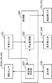
図2は、本発明の実施の形態における障害物検出装置の構成を示すブロック図である。建設機械1は、測距センサ40(物体検出部の一例)、角度センサ210、制御部220、表示部230、走行停止弁241,242、及び旋回停止弁251,252を備える。
FIG. 2 is a block diagram showing a configuration of the obstacle detection device in the embodiment of the present invention. The
測距センサ40は、上部旋回体3に設けられた3次元測距センサで構成され、建設機械1の周囲に位置する物体の3次元位置を検出する。測距センサ40は、例えば、一定の時間毎(例えば30fps)で赤外線を照射し、赤外線を照射してから反射光を受信するまでの時間を画素単位で計測するTOF(Time of flight)方式の3次元測距センサで構成されている。そして、測距センサ40は、建設機械1の周辺環境の距離分布を距離に応じたコントラストで示す距離画像を30fpsのフレームレートで取得する。
The
ここでは、測距センサ40としては、ステレオカメラが採用されてもよい。
Here, a stereo camera may be adopted as the
測距センサ40は、図5に示すように、上面視において、上部旋回体3の左側面3Lに設けられた測距センサ4Lと、上部旋回体3の右側面3Rに設けられた測距センサ4Rと、上部旋回体3の後側面3Bに設けられた測距センサ4Bとを備える。
As shown in FIG. 5, the
角度センサ210は、例えば、レゾルバで構成され、下部走行体2に対する上部旋回体3の旋回角度を検出する。
The
制御部220は、例えば、マイクロコントローラで構成され、障害物判定部221及び停止制御部222を備える。障害物判定部221及び停止制御部222は、例えば、CPUがプログラムを実行することで実現されてもよいし、専用のハードウェア回路で実現されてもよい。
The
障害物判定部221は、測距センサ40により検出された物体が、オペレータの死角を含む領域に設定された監視領域に位置する場合、検出された物体を障害物として判定する。そして、障害物判定部221は、角度センサ210により検出された旋回角度に応じて、下部走行体2を示す領域が除外されるように監視領域を変更する。
When the object detected by the
停止制御部222は、角度センサ210により検出された旋回角度に基づいて、下部走行体2及び上部旋回体3の少なくとも一方の構成要素のうち、動作することで、建設機械1が障害物と衝突する可能性のある構成要素を判定し、判定した構成要素の動作を停止させる。
The
表示部230は、液晶ディスプレイ等の表示装置で構成され、距離画像から障害物以外の画像が除去された障害物画像を表示すると共に、建設機械に対してどの位置に障害物が存在するかを示す俯瞰画像とを表示する。また、表示部230は、スピーカを備え、障害物が存在すると判定された場合、スピーカから警報音を出力させる。
The
走行停止弁241は、例えば、電磁比例弁で構成され、停止制御部222から自動停止の制御指令が出力されると、下部走行体2の前進動作を強制的に停止させる。走行停止弁242は、例えば、電磁比例弁で構成され、停止制御部222から自動停止の制御指令が出力されると、下部走行体2の後進動作を強制的に停止させる。
The
旋回停止弁251は、例えば、電磁比例弁で構成され、停止制御部222から自動停止の制御指令が出力されると、上部旋回体3の右旋回動作を強制的に停止させる。旋回停止弁252は、例えば、電磁比例弁で構成され、停止制御部222から自動停止の制御指令が出力されると、上部旋回体3の左旋回動作を強制的に停止させる。
The swing stop valve 251 is configured by, for example, an electromagnetic proportional valve, and when the
図3は、本発明の実施の形態における障害物検出装置の油圧回路を示す図である。図3は、下部走行体2の油圧回路が示されている。この油圧回路は、操作部31、走行停止弁241、242、コントロールバルブ34、油圧ポンプ35、走行モータ36、圧力センサ37、38を備える。そして、この油圧回路では、操作部31の操作量に応じたパイロット圧をコントロールバルブ34に供給し、コントロールバルブ34が、パイロット圧に応じて、油圧ポンプ35から供給される作動油の流量及び方向を制御し、走行モータ36がコントロールバルブ34から供給される作動油に従って作動する。
FIG. 3 is a diagram showing a hydraulic circuit of the obstacle detection device according to the embodiment of the present invention. FIG. 3 shows a hydraulic circuit of the
コントロールバルブ34は、パイロットポート34a、34bを有するパイロット切替弁を備える。コントロールバルブ34は、パイロットポート34aにパイロット圧が供給されると、油圧管路51aを通じて走行モータ36のポート36aに作動油を供給する。一方、コントロールバルブ34は、パイロットポート34bにパイロット圧が供給されると、油圧管路51bを通じて走行モータ36のポート36bに作動油を供給する。
The
操作部31は、操作レバー31aを含むリモコン弁で構成され、操作レバー31aの操作量に応じたパイロット圧を出力する。ここで、操作部31は、操作レバー31aが下部走行体2を前進させる方向に操作されると、操作量に応じたパイロット圧をパイロット管路39aを通じてパイロットポート34aに入力する。一方、操作部31は、操作レバー31aが下部走行体2を後進させる方向に操作されると、操作量に応じたパイロット圧をパイロット管路39bを介してパイロットポート34bに出力する。
The
走行モータ36は、油圧モータで構成され、ポート36aに作動油が供給されると、下部走行体2を前進させ、ポート36bに作動油が供給されると、下部走行体2を後進させる。
The traveling
走行停止弁241は、パイロット管路39aに設けられている。走行停止弁242は、パイロット管路39bに設けられている。走行停止弁241は、制御部220から自動停止の制御指令が出力されると、パイロット管路39aを遮断して、パイロットポート34aへのパイロット圧の入力を阻止する。これにより、前進操作が入力されても、前進動作は行われない。走行停止弁242は、制御部220から自動停止の制御指令が出力されると、パイロット管路39bを遮断して、パイロットポート34bへのパイロット圧の入力を阻止する。これにより、後進操作が入力されても後進動作は行われない。
The
圧力センサ37、38は、それぞれ、パイロット管路39a、39bに設けられ、パイロット圧を検出し、制御部220に出力する。このパイロット圧は、制御部220が操作部31においてオペレータの操作が入力されているか否かを判断する際に用いられる。
The
以上、下部走行体2の油圧回路を説明したが、上部旋回体3を旋回動作させる油圧回路も図3と同一構成が採用される。この場合、図3において、走行モータ36が旋回モータとなり、操作部31が旋回操作を入力するための操作部となり、走行停止弁241が右旋回を自動停止させるための旋回停止弁となり、走行停止弁242が左旋回を自動停止させるための旋回停止弁となる。
The hydraulic circuit of the
図5は、図1に示す建設機械1を上側から見たときの外観図である。図5において、前方向は下部走行体2の前進方向を指し、後方向は下部走行体2の後進方向を指す。以下、前方向と後方向とを総称する方向を、前後方向と呼ぶ。左方向は下部走行体2を後方から前方に見たときの左側の方向を指し、右方向は下部走行体2を後方から前方に見たときの右側の方向を指す。以下、右方向と左方向とを総称する方向を、左右方向と呼ぶ。
FIG. 5 is an external view of the
上部旋回体3は、上面視において、四角形状を持ち、前側面3F、左側面3L、右側面3R、及び後側面3Bを備える。前側面3Fには前方に向けて作業装置4が延設されている。左側面3Lの前後方向のほぼ中間位置には測距センサ4Lが設けられている。右側面3Rの前後方向のほぼ中間位置には測距センサ4Rが設けられている。この例では、測距センサ4L、4Rは、上部旋回体3において左右対称に取り付けられている。後側面3Bの左右方向のほぼ中間位置には測距センサ4Bが設けられている。
The
キャビン3Cは、上面視において、上部旋回体3の左上に配置され、オペレータが搭乗する。上述した表示部230及び操作部31はキャビン3C内に設けられている。
The
図6は、上部旋回体3が下部走行体2に対して旋回したときの上面視における建設機械1を示した外観図である。旋回角度αは、下部走行体2の前方の方向H1に対する、上部旋回体3の前方の方向H2の角度によって規定される。方向H1は、前後方向と平行である。方向H2は、上部旋回体3の長手方向であり、前側面3Fと直交する方向である。以下、方向H1と方向H2とが同一方向を向いている場合、旋回角度αを0度とする。また、上部旋回体3の右旋回量が増大するにつれて、旋回角度αはプラス方向に増大し、上部旋回体3の左旋回量が増大するにつれて、旋回角度αはマイナス方向に増大するものとする。
FIG. 6 is an external view showing the
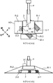
図7は、建設機械1の周囲に設定された監視領域R−1、R−2、R−3を示す図である。以下、監視領域R−1、R−2、R−3を総称する場合、監視領域Rと記述する。図7のセクション(a)は上面視からの監視領域Rを示し、セクション(b)は側面視からの監視領域Rを示す。
FIG. 7 is a diagram showing monitoring areas R-1, R-2, and R-3 set around the
監視領域Rは、オペレータが直接目視することが困難な領域に設定されている。図7では、旋回角度α=0度の場合に設定される監視領域Rが示されている。図7のセクション(a)に示すように、監視領域R−1は、上部旋回体3の右方に設けられた監視領域Rであり、測距センサ4Rが物体を検出することができる検出領域内に設定される。このことは、他の監視領域R−2、R−3も同じである。
The monitoring area R is set in an area that is difficult for the operator to directly visually observe. FIG. 7 shows the monitoring region R set when the turning angle α=0 degree. As shown in the section (a) of FIG. 7, the monitoring area R-1 is a monitoring area R provided on the right side of the
監視領域R−1は、上面視において、前方の辺K1は、前側面3Fと面一に設定され、内側の辺K2は右側面3Rに沿って設定され、外側の辺K3は後方に向けて左右方向の幅が短くなるように湾曲した形状に設定されている。なお、辺K3は、上部旋回体3の左旋回時の右下の頂点C1の軌跡に沿った形状を有している。これは、上部旋回体3が左旋回をした時に、辺K3の外側の領域に位置する物体は上部旋回体3と衝突する可能性が低いことを考慮したためである。
The front side K1 of the monitoring area R-1 is set flush with the
監視領域R−2は、上部旋回体3の左方に設けられた監視領域Rである。監視領域R−2は、上面視において、監視領域R−1と左右対称な形状を持っている。
The monitoring area R-2 is a monitoring area R provided on the left side of the
監視領域R−3は、上部旋回体3の後方に設けられた監視領域Rである。監視領域R−3は、上面視において、四角形状に設定されており、左右方向の幅は、後側面3Bの左右方向の幅よりも多少大きな長さに設定されている。
The monitoring area R-3 is a monitoring area R provided behind the
監視領域R−3が四角形状に設定されているのは、上面視において、後側面3Bが左右方向と平行であることを考慮したためである。したがって、後側面3Bが湾曲した形状を持つのであれば、監視領域R−3は、後側面3Bの形状に沿って湾曲させればよい。
The monitoring region R-3 is set in a quadrangular shape in consideration of the fact that the
図7のセクション(b)に示すように、監視領域R−1は、側面視において、測距センサ4Rを上側の頂点とする三角形の形状を持ち、画角βの中心線L1が地面に向かうように右斜め下方に設定されている。なお、中心線L1は、左方向視において、上下方向を向いている。監視領域R−1を後方から前方に見た場合の監視領域R−1が側面視の監視領域R−1である。図7のセクション(b)の例では、監視領域R−1は、例えば、中心線L1で2等分されるように画角βが設定されている。監視領域R−1は、側面視において、下方の辺K5は地面と平行に設定され、内側の辺K6は下部走行体2と接しないように右斜め下方を向くように設定され、外側の辺K7は辺K6と画角βを挟んで右斜め下方を向くように設定されている。
As shown in the section (b) of FIG. 7, the monitoring region R-1 has a triangular shape with the
図7のセクション(b)に示すように、監視領域R−2は、側面視において、監視領域R−1と左右対称に設定されている。すなわち、監視領域R−2は、側面視において、測距センサ4Lを頂点とし、画角βの中心線L2が左斜め下方を向くように設定されている。
As shown in the section (b) of FIG. 7, the monitoring area R-2 is set symmetrically with the monitoring area R-1 in a side view. That is, the monitoring region R-2 is set such that the center line L2 of the angle of view β faces diagonally downward left with the
側面視における監視領域R−3は、図示は省略しているが、監視領域R−1、R−2と同様、中心線が右斜め後方を向くように設定された三角形の形状を持つ。 Although not shown, the monitoring region R-3 in side view has a triangular shape in which the center line is set so as to face the diagonally right rear, like the monitoring regions R-1 and R-2.
上述のように、障害物判定部221は、角度センサ210により検出された旋回角度に応じて、下部走行体2を示す領域が除外されるように監視領域を設定するが、本実施の形態では、障害物判定部221は、下記の2つの手法を用いて、これを実現する。
As described above, the
(手法1)
手法1では、障害物判定部221は、旋回角度αに応じて、下部走行体が除外される予め定められた画角に、測距センサ40の画角を設定する。
(Method 1)
In the
図8は、手法1の説明図であり、上部旋回体3が旋回角度α(>0)で旋回したときの監視領域Rを示す図である。図8のセクション(a)は上面視からの監視領域Rを示し、セクション(b)は上部旋回体3を後方から前方を見たときの監視領域Rを示す。
FIG. 8 is an explanatory diagram of
図8のセクション(a)に示すように、上部旋回体3が旋回した場合、監視領域R−1は、上面視において、下部走行体2の全域を覆うサイズの四角形の形状を持つ。横辺K8は、上部旋回体3から右方向にはみ出た下部走行体2の横方向の長さに、多少のマージンを加えた長さを持つ。縦辺K9は、右側面3Rの縦方向の長さと同じ長さを持つ。
As shown in section (a) of FIG. 8, when the
監視領域R−2は、上面視において、監視領域R−1と左右対称な四角形の形状を持つ。監視領域R−3は、上面視において、図7のセクション(a)の監視領域R−3と同じである。 The monitoring region R-2 has a quadrangular shape that is symmetrical to the monitoring region R-1 in a top view. The monitoring area R-3 is the same as the monitoring area R-3 in the section (a) of FIG. 7 in a top view.
図8のセクション(a)の例では、上部旋回体3は、下部走行体2に対して、右側の方が左側より横方向に多くはみ出ているので、監視領域R−1のサイズと同一サイズに監視領域R−2が設定されている。上部旋回体3に対する、上部旋回体2の横方向にはみ出た量が、左側の方が右側よりも多ければ、監視領域R−2のサイズと同一サイズに監視領域R−1が設定される。
In the example of the section (a) of FIG. 8, the upper revolving
図8のセクション(b)に示すように、手法1では、側面視において、監視領域R−1は、下部走行体2と重ならないように画角βが設定されている。具体的には、監視領域R−1は、辺K6が下部走行体2の少し外側を通るように画角βが設定されている。
As shown in the section (b) of FIG. 8, in the
側面視において、監視領域R−2は、監視領域R−1と左右対称に設定されている。ここで、上部旋回体3に対して、下部走行体2の横方向にはみ出た量が、右側の方が左側よりも多ければ、監視領域R−1のサイズを基準に監視領域R−2は設定されればよい。一方、上部旋回体3に対して、下部走行体2の横方向にはみ出た量が、左側の方が右側よりも多ければ、監視領域R−2のサイズを基準に監視領域R−1は設定されればよい。
In a side view, the monitoring area R-2 is set symmetrically with the monitoring area R-1. Here, if the amount of protrusion of the
なお、図8の例では、上部旋回体3が旋回しても、下部走行体2が上部旋回体3の後方にはみ出る量は僅かであるので、監視領域R−3の画角βは変更されていない。但し、これは一例であり、監視領域R−3も、監視領域R−1、R−2と同様、下部走行体2が含まれないように画角が設定されてもよい。
In the example of FIG. 8, even if the upper revolving
上部旋回体3に対し、下部走行体2がはみ出る領域は、旋回角度αに応じて変化するが、この領域の大きさは予め測定により知ることができる。そこで、本実施の形態では、障害物判定部221は、旋回角度αと、下部走行体2が監視領域Rと重ならない画角βとの関係が予め対応付けられたテーブルを記憶しておき、このテーブルを参照して、旋回角度αに応じた画角βを設定すればよい。
The area where the
なお、図8のセクション(b)の例では、監視領域R−1及び監視領域R−2は左右対称に設定されているが、これは一例である。例えば、監視領域R−1及び監視領域R−2は、それぞれ、下部走行体2と重ならないように、個別に画角βR、βLが設定されてもよい。
In addition, in the example of the section (b) of FIG. 8, the monitoring region R-1 and the monitoring region R-2 are set symmetrically, but this is an example. For example, the angle of view βR and βL may be individually set for the monitoring region R-1 and the monitoring region R-2 so that they do not overlap the
この場合、障害物判定部221は、旋回角度αと、画角βR、βLとがそれぞれ対応付けられたテーブルを用いて、画角βR、βLを決定すればよい。
In this case, the
図4は、測距センサ40の開口部405付近の構成の一例を示した図である。測距センサ40は、光源401、レンズ402、及び左右一対のシャッター403、404を備える。光源401は、例えば、赤外線を照射する発光ダイオードで構成されている。レンズ402は、光源401から照射された赤外光を拡散させる。レンズ402を通過した赤外光は、シャッター403、404により両端の一部が遮られて、開口部405から外部に照射される。
FIG. 4 is a diagram showing an example of a configuration in the vicinity of the
シャッター403、404は、図略のアクチュエータからの動力を受けて、矢印で示す横方向にスライド自在に配置されている。ここで、シャッター403、404は、アクチュエータが順方向に回転すると、例えば、左右均等に近づいていき、アクチュエータが逆方向に回転すると、左右均等に遠ざかっていくように構成されている。
The
したがって、障害物判定部221は、画角βを狭めるときはアクチュエータを順方向に回転させ、画角βを拡げるときはアクチュエータを逆方向に回転させることで、画角βを調整すればよい。
Therefore, the
(手法2)
手法2では、障害物判定部221は、旋回角度αに応じて予め定められた下部走行体2の領域が除外されるように、距離画像に監視領域Rを設定する。手法2では、測距センサ40の画角βは調整されない。
(Method 2)
In the
図9は、手法2の説明図であり、上部旋回体3が旋回角度α(>0)で旋回したときの監視領域Rを示す図である。図9のセクション(a)は上面視からの監視領域Rを示し、セクション(b)は後方から前方を見たときの監視領域Rを示す。図9のセクション(a)に示すように、監視領域R−1、R−2は、上面視において、図8のセクション(a)と同様、左右対称の四角形の外周形状を持っている。
FIG. 9 is an explanatory diagram of the
この例では、上部旋回体3は、右回りに旋回角度αだけ旋回しているので、下部走行体2は、右側のクローラの後端側が、右斜め下方に向けて右側面3Rからはみ出ており、左側のクローラの後端側が、右斜め下方に向けて後側面3Bからはみ出ており、右側のクローラの前端側が、左斜め上方に向けて左側面3Lからはみ出ている。
In this example, the upper revolving
そこで、図9のセクション(a)に示すように、上部旋回体3からはみ出た下部走行体2の領域に除外領域D−1、D−2、D−3が設定され、除外領域D−1、D−2、D−3が、それぞれ、監視領域R−1、R−2、R−3から除外されている。以下、除外領域D−1、D−2、D−3を総称する場合、除外領域Dと記述する。
Therefore, as shown in the section (a) of FIG. 9, exclusion areas D-1, D-2, and D-3 are set in the area of the
また、図9のセクション(b)に示すように、監視領域R−1、R−2は、側面視において、図7のセクション(b)と同様、左右対称な三角形の外周形状を持っている。下部走行体2の右側のクローラは後端側が上部旋回体3からはみ出しており、左側のクローラは前端側が上部旋回体3からはみ出している。
Further, as shown in the section (b) of FIG. 9, the monitoring regions R-1 and R-2 have a laterally symmetrical triangular outer peripheral shape in a side view, like the section (b) of FIG. 7. .. The right crawler of the
そこで、図9のセクション(b)に示すように、上部旋回体3からはみ出た下部走行体2の領域に除外領域D−1、D−2が設定され、除外領域D−1、D−2が除外されるように監視領域R−1、R−2が設定されている。
Therefore, as shown in the section (b) of FIG. 9, exclusion areas D-1 and D-2 are set in the area of the
図9から分かるように、除外領域Dは、それぞれ、上部旋回体3からはみ出た下部走行体2の部分を覆うような3次元形状を持っている。ここで、旋回角度αが分かれば、測距センサ40の座標空間において、どの領域が除外領域Dに該当するかは、下部走行体2の形状や、測距センサ40の取り付け位置から事前に求めることができる。そこで、障害物判定部221は、測距センサ4R、4L、4Bのそれぞれの距離画像において、旋回角度αと、除外領域D−1、D−2、D−3が除去された監視領域R−1、R−2、R−3との関係が対応付けられたテーブルを備えておき、このテーブルを参照することで、旋回角度αに応じた監視領域Rを設定すればよい。
As can be seen from FIG. 9, each of the exclusion areas D has a three-dimensional shape that covers the portion of the
図10は、本発明の実施の形態における障害物検出装置の処理を示すフローチャートである。このフローチャートは、例えば、測距センサ40により取得された距離画像において、障害物判定部221が物体を検出した場合に実行される。
FIG. 10 is a flowchart showing processing of the obstacle detection device in the embodiment of the present invention. This flowchart is executed, for example, when the
まず、角度センサ210は、旋回角度αを検出する(S101)。次に、障害物判定部221は、旋回角度αに応じた監視領域R−1、R−2、R−3を設定する。ここで、手法1が採用されるのであれば、下部走行体2が含まれないように画角βが調整されることで監視領域R−1、R−2、R−3が設定される。また、手法2が採用されるのであれば、距離画像において、除外領域D−1、D−2、D−3が除外されるように監視領域R−1、R−2、R−3が設定される。
First, the
次に、障害物判定部221は、監視領域R−1若しくはR−2に物体が侵入したか否かを判定する(S103)。ここで、障害物判定部221は、距離画像において、距離が連続する一群の画素群を1つの物体として検出し、その物体の一部が監視領域R−1若しくはR−2に侵入していれば、その物体が監視領域R−1若しくはR−2に侵入したと判定すればよい。そして、障害物判定部221は、監視領域R−1若しくはR−2に侵入した物体を障害物として判定する。このことは、監視領域R−3においても同じである。
Next, the
監視領域R−1若しくはR−2に物体が侵入していれば(S103でYES)、障害物判定部221は、上部旋回体3と下部走行体2とは同じ方向を向いているか否かを判定する(S106)。ここで、同じ方向とは、旋回角度αが実質的に0度であることを指す。実質的に0度とは旋回角度αが0度に限定されず、0度に対してプラス方向、マイナス方向に一定のマージンを加えた角度範囲を含むことを意味する。マージンとしては、例えば、図6のセクション(a)に示すように、上部旋回体3が多少旋回しても、上部旋回体3が下部走行体2から左右方向にはみ出さない程度の角度が採用できる。
If an object has entered the monitoring area R-1 or R-2 (YES in S103), the
上部旋回体3と下部走行体2とが同じ方向を向いていなければ(S106でNO)、停止制御部222は、下部走行体2及び上部旋回体3のいずれか一方が動作すると、建設機械1と障害物と衝突する可能性があると判定し、下部走行体2の走行動作及び上部旋回体3の旋回動作を自動停止させる(S107)。ここで、停止制御部222は、自動停止の制御信号を走行停止弁241,242と旋回停止弁251,252とに出力することで、走行動作及び旋回動作を停止させればよい。
If the
上部旋回体3と下部走行体2とが同じ方向を向いていれば(S106でYES)、停止制御部222は、上部旋回体3が動作すると、建設機械1が障害物と衝突する可能性があると判定し、上部旋回体3のみを自動停止させる(S108)。ここで、停止制御部222は、旋回停止弁251,252に自動停止の制御信号を出力することで、上部旋回体3を自動停止させればよい。
If the
図7のセクション(a)に示すように、障害物が監視領域R−1若しくはR−2に位置する場合において、上部旋回体3と下部走行体2とが同じ方向を向いているケース(1:S106でYES)では、下部走行体2が前方又は後方に走行したとしても、建設機械1は障害物と衝突する可能性は低いので、下部走行体2の走行動作を停止させる必要はない。
As shown in the section (a) of FIG. 7, when the obstacle is located in the monitoring area R-1 or R-2, the
そこで、本実施の形態では、ケース(1)の場合、上部旋回体3の旋回動作のみを自動停止させている(S108)。
Therefore, in the present embodiment, in case (1), only the turning operation of the upper-
一方、図8のセクション(a)を参照し、障害物が監視領域R−1若しくはR−2に位置する場合において、上部旋回体3と下部走行体2とが同一方向を向いていないケース(2:S106でNO)では、下部走行体2が上部旋回体3からはみ出るので、走行動作及び旋回動作のいずれか一方が行われると、建設機械1は障害物と衝突する可能性がある。
On the other hand, referring to the section (a) of FIG. 8, when the obstacle is located in the monitoring area R-1 or R-2, the case where the
そこで、本実施の形態では、ケース(2)の場合、上部旋回体3及び下部走行体2の動作を共に停止させている(S107)。
Therefore, in the present embodiment, in the case (2), the operations of the
物体が監視領域R−1若しくはR−2に侵入していないが(S103でNO)、監視領域R−3に侵入していれば(S104でYES)、障害物判定部221は、その物体を障害物と判定し、上部旋回体3と下部走行体2とが横向き姿勢をとっているかを判定する(S105)。ここで、横向き姿勢とは、旋回角度αの絶対値が実質的に90度であることを指す。実質的に90度とは旋回角度αの絶対値が90度に限定されず、90度に対して、プラス方向、マイナス方向に一定のマージンを加えた角度範囲が含まれることを意味する。マージンとしては、例えば、1〜10度の範囲内の角度が採用できるがこれは一例である。
If the object has not entered the monitoring area R-1 or R-2 (NO in S103) but has entered the monitoring area R-3 (YES in S104), the
図8のセクション(a)に示すように、監視領域R−3に障害物が位置する場合において、上部旋回体3が下部走行体2に対して横向き姿勢をとっていないケース(3:S105でNO)では、下部走行体2が走行動作を行うと、建設機械1は障害物と衝突する可能性がある。しかし、ケース(3)では旋回動作を行っても、建設機械1が障害物と衝突する可能性が低い。そこで、本実施の形態では、ケース(3)において、停止制御部222は、下部走行体2が動作すると、建設機械1が障害物と衝突する可能性があると判定し、下部走行体2の走行動作のみを停止させている(S109)。
As shown in the section (a) of FIG. 8, when the obstacle is located in the monitoring area R-3, the
一方、図8のセクション(a)から類推すれば分かるように、監視領域R−3に障害物が位置する場合において、上部旋回体3が下部走行体2に対して横向き姿勢をとっているケース(4:S105でYES)では、下部走行体2が走行動作を行っても、上部旋回体3の後方に下部走行体2ははみ出ていないので、旋回動作及び走行動作のいずれか一方又は両方が行われたとしても、建設機械1は障害物と衝突する可能性は低い。
On the other hand, as can be understood by analogy from the section (a) of FIG. 8, the case in which the
そこで、本実施の形態では、ケース(4)の場合、走行動作及び旋回動作は共に自動停止されず、処理はS101に戻される。 Therefore, in the present embodiment, in case (4), neither the traveling operation nor the turning operation is automatically stopped, and the process returns to S101.
また、物体が監視領域R−1、R−2、R−3のいずれにも侵入していなければ(S103でNO、S104でNO)、処理はS101に戻され、物体の監視が継続される。 If the object has not entered any of the monitoring areas R-1, R-2, R-3 (NO in S103, NO in S104), the process returns to S101 to continue monitoring the object. ..
S110では、障害物判定部221は、測距センサ40が取得した距離画像から障害物以外の領域が除去された障害物画像と、建設機械1に対する障害物の相対的な位置を示す俯瞰画像とを表示部230にする。
In S110, the
ここで、障害物判定部221は、測距センサ4L、4R、4Bがそれぞれ取得した距離画像を繋ぎ合わせ、障害物と判定した物体以外の物体を除去することで障害物画像を生成し、表示部230に表示させればよい。距離画像は、可視画像とは異なり、距離に応じたコントラストを持つ画像であるため、距離画像を表示部230にそのまま表示しても、どの物体が障害物であるかをオペレータに認識させることは困難である。そこで、本実施の形態では、障害物以外の物体を除去することで障害物画像を生成し、表示部230に表示させている。これにより、障害物のシルエットが明確化され、オペレータは障害物が何であるかを即座に判断できる。
Here, the
障害物画像では、障害物のみが表示されているので、オペレータは、障害物が建設機械1に対してどの場所に位置にするのかを認識できない。そこで、本実施の形態では、障害物画像と合わせて俯瞰画像を生成し、表示部230に表示させている。
Since only the obstacle is displayed in the obstacle image, the operator cannot recognize where the obstacle is located with respect to the
ここで、障害物判定部221は、測距センサ40で取得された距離画像から、建設機械1に対する障害物の相対的な位置を算出する。そして、障害物判定部221は、上面視の建設機械1の画像を含み、その画像の周囲に障害物を示すマークがマーキングされた俯瞰画像を生成し、表示部230に表示させればよい。なお、表示部230は、表示領域を2つに分け、一方の表示領域に障害物画像を表示させ、他方の表示領域に俯瞰画像を表示させればよい。
Here, the
このように、障害物画像に合わせて俯瞰画像を表示することで、オペレータは建設機械1に対して、どの位置にどのような障害物が存在するかを速やかに認識できる。
In this way, by displaying the bird's-eye view image in accordance with the obstacle image, the operator can quickly recognize what kind of obstacle exists at which position on the
次に、障害物判定部221は、監視領域Rから障害物が無くなったか否かを確認する(S111)。監視領域Rから障害物が無くなっていれば(S111でYES)、障害物判定部221は、リセット処理を実行し(S112)、処理を終了する。一方、監視領域Rから障害物が無くなっていなければ(S111でNO)、処理がS103に戻され、監視領域Rから障害物が無くなるまでS103〜S111の処理が繰り返される。S111では、例えば、障害物が人物であれば、オペレータがその人物に注意喚起を行うことで、障害物が監視領域Rから除去される。また、障害物が人物でなければ、オペレータが障害物を移動させる或いは建設機械1を移動させることで、障害物が監視領域Rから除去される。
Next, the
S112のリセット処理では、例えば、S102で設定された監視領域Rを解除する処理が行われる。以降、障害物判定部221は、測距センサ40が取得する距離画像から建設機械1の周囲をモニタし、何らかの物体を検出すると、図10のフローチャートを開始する。
In the reset process of S112, for example, a process of canceling the monitoring area R set in S102 is performed. After that, the
このように、本実施の形態によれば、旋回角度αに応じて下部走行体2を示す領域が除外されるように監視領域Rが設定されている。そのため、監視領域Rを広く設定したとしても、この下部走行体2が障害物として判定されることが防止され、建設機械1を自動停止させたり、警報を報知するといった干渉回避措置が頻発されることを防止できる。
As described above, according to the present embodiment, the monitoring region R is set so that the region indicating the
なお、本発明は以下の変形例が採用できる。 The present invention can adopt the following modified examples.
(1)変形例1
図11は、本発明の変形例1における監視領域R−3を示す図である。図11の建設機械1は、下部走行体2の上下方向の長さが上部旋回体3の上下方向の長さよりも長い。そのため、上部旋回体3が下部走行体2と同じ方向を向いている場合であっても、下部走行体2の後端側が上部旋回体3の後側面3Bからはみ出ている。
(1)
FIG. 11: is a figure which shows the monitoring area|region R-3 in the
この場合、障害物判定部221は、右側のクローラの後側面3Bからはみ出た部分を含む除外領域D−4と、左側のクローラの後側面3Bからはみ出た部分を含む除外領域D−5とが除去されるように、監視領域R−3を設定すればよい。ここで、除外領域D−4、D−5は旋回角度αに応じて変化するが、旋回角度αと除外領域D−4、D−5との関係は事前に分かる。そこで、障害物判定部221は、旋回角度αと除外領域D−4、D−5が除去された監視領域R−3との関係が予め対応付けられたテーブルを備え、このテーブルを参照することで、監視領域R−3を設定すればよい。
In this case, the
(2)変形例2
図12は、本発明の変形例2における監視領域Rを示す図である。図12において、セクション(a)は上面視の監視領域R−1、R−2を示し、セクション(b)は後方から前方に向けて建設機械1を見たときの監視領域R−1、R−2を示している。図12では、上部旋回体3と下部走行体2とは旋回角度αが90度であり、上部旋回体3は下部走行体2に対して横向き姿勢をとっている。
(2)
FIG. 12 is a diagram showing a monitoring region R in the second modification of the present invention. In FIG. 12, the section (a) shows the monitoring regions R-1 and R-2 in a top view, and the section (b) shows the monitoring regions R-1 and R when the
図12のセクション(a)を参照する。上部旋回体3の後方に障害物が存在している場合において、旋回角度αが90度であれば、下部走行体2が前後方向に移動する、或いは、上部旋回体3が旋回しても、建設機械1が障害物と衝突する可能性は低い。この場合、上部旋回体3の後方に監視領域R−3を設定する必要はない。
See section (a) of FIG. When there is an obstacle behind the
そこで、変形例2では、上部旋回体3が下部走行体2に対して横向き姿勢をとっている場合、監視領域R−1、R−2のみ設定し、監視領域R−3を設定しないようにしている。これにより、監視領域R−3に物体が侵入したか否かを判定する処理が不要となり、処理負担を軽減できる。
Therefore, in the second modification, when the
なお、図12のセクション(b)に示すように、変形例2では、監視領域R−1、R−2は、図8のセクション(b)と同様、下部走行体2が含まれないように画角βが設定されている。
As shown in the section (b) of FIG. 12, in the modified example 2, the monitoring areas R-1 and R-2 do not include the
(3)変形例3
監視領域R−1若しくはR−2と、監視領域R−3とのそれぞれに障害物が侵入した場合、停止制御部222は、旋回角度αに拘わらず、旋回動作と走行動作との両方を自動停止させてもよい。
(3)
When an obstacle enters each of the monitoring area R-1 or R-2 and the monitoring area R-3, the
D−1、D−2、D−3、D−4、D−5 除外領域
R−1、R−2、R−3 監視領域
α 旋回角度
β 画角
1 建設機械
2 下部走行体
3 上部旋回体
3B 後側面
3F 前側面
3L 左側面
3R 右側面
40 測距センサ
210 角度センサ
220 制御部
221 障害物判定部
222 停止制御部
230 表示部
241,242 走行停止弁
251,252 旋回停止弁
D-1, D-2, D-3, D-4, D-5 Exclusion area R-1, R-2, R-3 Monitoring area α Turning angle β Angle of
Claims (9)
前記上部旋回体に設けられ、前記建設機械の周囲に位置する物体の3次元位置を検出する物体検出部と、
前記上部旋回体の前記下部走行体に対する旋回角度を検出する角度検出部と、
前記検出された旋回角度に応じて予め定められた前記建設機械の構成要素を示す領域が除外されるように前記建設機械の周囲に設定された監視領域を設定し、前記設定した監視領域に、前記物体検出部により検出された物体が位置する場合、当該物体を障害物として判定する障害物判定部とを備える障害物検出装置。 An obstacle detection device for a construction machine, comprising an undercarriage and an upper revolving structure which is rotatably attached to an upper part of the undercarriage,
An object detection unit which is provided on the upper swing body and detects a three-dimensional position of an object located around the construction machine;
An angle detection unit that detects a turning angle of the upper swing body with respect to the lower traveling body,
Set a monitoring area set around the construction machine so as to exclude areas indicating the components of the construction machine that are predetermined according to the detected turning angle, and in the set monitoring area, An obstacle detection device comprising an obstacle determination unit that determines the object as an obstacle when the object detected by the object detection unit is located.
前記物体検出部は、前記建設機械の周囲の物体を距離に応じたコントラストで表した距離画像を取得し、
前記障害物判定部は、前記取得した距離画像から前記障害物以外を除去した障害物画像を前記表示部に表示させる請求項1〜4のいずれかに記載の障害物検出装置。 Further equipped with a display unit,
The object detection unit acquires a distance image that represents an object around the construction machine with a contrast according to a distance,
The obstacle detection device according to any one of claims 1 to 4, wherein the obstacle determination unit causes the display unit to display an obstacle image obtained by removing other than the obstacle from the acquired distance image.
前記障害物判定部は、前記旋回角度に応じて予め定められた前記下部走行体の領域が除外されるように、前記距離画像に監視領域を設定する請求項1〜5のいずれかに記載の障害物検出装置。 The object detection unit acquires a distance image that represents an object around the construction machine with a contrast according to a distance,
The said obstacle determination part sets the monitoring area|region to the said distance image so that the area|region of the said lower traveling body predetermined according to the said turning angle may be excluded. Obstacle detection device.
前記停止制御部は、
前記障害物が前記第1及び第2監視領域の少なくとも一方に位置する場合、
前記上部旋回体が前記下部走行体と同一方向を向いていれば、前記上部旋回体の旋回動作のみを停止させ、
前記上部旋回体が前記下部走行体と同一方向を向いていなければ、前記旋回動作及び前記下部走行体の走行動作を停止させる請求項3に記載の障害物検出装置。 The monitoring area includes a first monitoring area provided on the left side of the upper swing body and a second monitoring area provided on the right side of the upper swing body,
The stop control unit,
When the obstacle is located in at least one of the first and second monitoring areas,
If the upper revolving structure faces the same direction as the lower traveling structure, only the revolving operation of the upper revolving structure is stopped,
The obstacle detection device according to claim 3, wherein if the upper revolving structure does not face the same direction as the lower traveling structure, the revolving motion and the traveling motion of the lower traveling structure are stopped.
前記停止制御部は、前記障害物が前記第3監視領域に位置する場合、前記上部旋回体が前記下部走行体に対して横向き姿勢をとっていなければ、前記走行動作のみを停止させる
請求項8記載の障害物検出装置。 The monitoring area further includes a third monitoring area provided behind the upper swing body,
The stop control unit stops only the traveling operation when the obstacle is located in the third monitoring area and the upper revolving structure does not have a lateral posture with respect to the lower traveling structure. The obstacle detection device described.
Priority Applications (5)
| Application Number | Priority Date | Filing Date | Title |
|---|---|---|---|
| JP2016153011A JP6729146B2 (en) | 2016-08-03 | 2016-08-03 | Obstacle detection device |
| US16/321,521 US10527731B2 (en) | 2016-08-03 | 2017-06-14 | Obstacle detection device |
| CN201780047835.4A CN109563693A (en) | 2016-08-03 | 2017-06-14 | Obstacle detector |
| EP17836619.1A EP3477006B1 (en) | 2016-08-03 | 2017-06-14 | Obstacle detection device for a construction machine |
| PCT/JP2017/022017 WO2018025512A1 (en) | 2016-08-03 | 2017-06-14 | Obstacle detection device |
Applications Claiming Priority (1)
| Application Number | Priority Date | Filing Date | Title |
|---|---|---|---|
| JP2016153011A JP6729146B2 (en) | 2016-08-03 | 2016-08-03 | Obstacle detection device |
Publications (2)
| Publication Number | Publication Date |
|---|---|
| JP2018021374A JP2018021374A (en) | 2018-02-08 |
| JP6729146B2 true JP6729146B2 (en) | 2020-07-22 |
Family
ID=61072911
Family Applications (1)
| Application Number | Title | Priority Date | Filing Date |
|---|---|---|---|
| JP2016153011A Active JP6729146B2 (en) | 2016-08-03 | 2016-08-03 | Obstacle detection device |
Country Status (5)
| Country | Link |
|---|---|
| US (1) | US10527731B2 (en) |
| EP (1) | EP3477006B1 (en) |
| JP (1) | JP6729146B2 (en) |
| CN (1) | CN109563693A (en) |
| WO (1) | WO2018025512A1 (en) |
Families Citing this family (36)
| Publication number | Priority date | Publication date | Assignee | Title |
|---|---|---|---|---|
| CN115092032A (en) * | 2016-07-20 | 2022-09-23 | 普瑞诺斯有限公司 | Tracked vehicle with rotatable superstructure and method therefor |
| JP6949483B2 (en) * | 2016-12-22 | 2021-10-13 | 株式会社クボタ | Work machine |
| JP6819462B2 (en) * | 2017-05-30 | 2021-01-27 | コベルコ建機株式会社 | Work machine |
| WO2019026802A1 (en) * | 2017-07-31 | 2019-02-07 | 住友重機械工業株式会社 | Excavator |
| JP6626138B2 (en) * | 2018-02-19 | 2019-12-25 | ファナック株式会社 | Object monitoring device using sensor |
| WO2019182066A1 (en) * | 2018-03-23 | 2019-09-26 | 住友重機械工業株式会社 | Shovel |
| EP3779066B1 (en) * | 2018-03-26 | 2023-10-25 | Sumitomo (S.H.I.) Construction Machinery Co., Ltd. | Shovel |
| JP7091772B2 (en) * | 2018-03-29 | 2022-06-28 | コベルコ建機株式会社 | Construction machinery |
| WO2019189589A1 (en) * | 2018-03-30 | 2019-10-03 | 住友建機株式会社 | Excavator |
| JP7206658B2 (en) * | 2018-07-12 | 2023-01-18 | コベルコ建機株式会社 | Safety device for swivel work machine |
| CA3108619A1 (en) | 2018-08-06 | 2020-02-13 | Clark Equipment Company | Object detection external to vehicle |
| JP7058582B2 (en) * | 2018-09-27 | 2022-04-22 | 日立建機株式会社 | Work machine |
| JP2020148074A (en) * | 2019-03-15 | 2020-09-17 | ヤンマーパワーテクノロジー株式会社 | Contact prevention device of work machine |
| KR20210140723A (en) * | 2019-03-28 | 2021-11-23 | 스미토모 겐키 가부시키가이샤 | Shovel and construction system |
| EP3959954A4 (en) * | 2019-04-25 | 2023-05-10 | Kubota Corporation | Harvester, obstacle determination program, recording medium on which obstacle determination program is recorded, obstacle determination method, agricultural work machine, control program, recording medium on which control program is recorded, and control method |
| JPWO2020218453A1 (en) * | 2019-04-26 | 2020-10-29 | ||
| EP3960938A4 (en) * | 2019-04-26 | 2022-06-22 | Sumitomo Construction Machinery Co., Ltd. | Excavator |
| JP7358070B2 (en) * | 2019-04-26 | 2023-10-10 | 住友建機株式会社 | excavator |
| WO2020235450A1 (en) * | 2019-05-17 | 2020-11-26 | コベルコ建機株式会社 | Work machine and video display control method for work machine |
| EP3943439A4 (en) * | 2019-05-17 | 2022-07-20 | Kobelco Construction Machinery Co., Ltd. | Work machine and method for controlling work machine |
| JP7379866B2 (en) * | 2019-05-21 | 2023-11-15 | コベルコ建機株式会社 | working machine |
| US10949685B2 (en) | 2019-07-22 | 2021-03-16 | Caterpillar Inc. | Excluding a component of a work machine from a video frame based on motion information |
| JP7416579B2 (en) * | 2019-08-09 | 2024-01-17 | 株式会社小松製作所 | working machine |
| WO2021085503A1 (en) * | 2019-10-31 | 2021-05-06 | 日立建機株式会社 | Work machine |
| JP7400425B2 (en) * | 2019-12-10 | 2023-12-19 | コベルコ建機株式会社 | Remote operation support system for working machines |
| IT201900023631A1 (en) * | 2019-12-11 | 2021-06-11 | Manitou Italia Srl | ROTATING TOWER WITH BALLAST. |
| CN111099504A (en) * | 2019-12-17 | 2020-05-05 | 北汽福田汽车股份有限公司 | Crane control method and device and vehicle |
| JP7421393B2 (en) | 2020-03-25 | 2024-01-24 | 日立建機株式会社 | working machine |
| US11421400B2 (en) * | 2020-04-23 | 2022-08-23 | Deere & Company | Multiple mode operational system and method with object detection |
| CN111526337B (en) * | 2020-05-08 | 2021-12-17 | 三一重机有限公司 | Early warning system and early warning method for engineering machinery and engineering machinery |
| DE102020214291B3 (en) * | 2020-11-13 | 2022-03-17 | Tadano Faun Gmbh | Crane, in particular mobile crane |
| CN112672047B (en) * | 2020-12-20 | 2022-08-26 | 英特睿达(山东)电子科技有限公司 | Image acquisition system and image processing method |
| JP2023049718A (en) * | 2021-09-29 | 2023-04-10 | 株式会社小松製作所 | Obstacle detection alarm system, obstacle detection alarm method, and working machine |
| WO2023105944A1 (en) * | 2021-12-10 | 2023-06-15 | 日立建機株式会社 | Work machine |
| US20230287655A1 (en) * | 2022-03-08 | 2023-09-14 | Caterpillar Sarl | Maintenance-service system |
| CN116295388B (en) * | 2023-05-11 | 2023-08-29 | 国网浙江宁波市鄞州区供电有限公司 | Power pipeline detection method, device and detector |
Family Cites Families (28)
| Publication number | Priority date | Publication date | Assignee | Title |
|---|---|---|---|---|
| JP2700710B2 (en) * | 1990-06-21 | 1998-01-21 | 新キャタピラー三菱株式会社 | Warning device for construction machinery |
| JP2002049403A (en) * | 2000-08-07 | 2002-02-15 | Shin Caterpillar Mitsubishi Ltd | Voice operated controller for construction equipment |
| JP3829071B2 (en) * | 2001-05-31 | 2006-10-04 | 新キャタピラー三菱株式会社 | Construction machinery |
| JP4133109B2 (en) * | 2002-08-20 | 2008-08-13 | 新キャタピラー三菱株式会社 | Shutter-type guard device for construction machinery |
| JP4332028B2 (en) * | 2003-12-25 | 2009-09-16 | キャタピラージャパン株式会社 | Display control system |
| JP2007023486A (en) | 2005-07-12 | 2007-02-01 | Shin Caterpillar Mitsubishi Ltd | Contact avoidance controller in working machine |
| CN101070706A (en) * | 2007-05-29 | 2007-11-14 | 三一重机有限公司 | Hydraulic-digger obstruction-avoiding control system and method |
| KR101403793B1 (en) * | 2007-12-26 | 2014-06-11 | 두산인프라코어 주식회사 | Dozer apparatus for backhoe |
| CN201180274Y (en) * | 2008-02-29 | 2009-01-14 | 田永昌 | Walking excavator for all landforms |
| JP4839390B2 (en) * | 2009-04-17 | 2011-12-21 | 株式会社神戸製鋼所 | Swing stop control device and method for swivel work machine |
| EP2563706B1 (en) * | 2010-04-29 | 2015-07-22 | National Oilwell Varco, L.P. | Videometric systems and methods for offshore and oil-well drilling |
| WO2011155749A2 (en) * | 2010-06-07 | 2011-12-15 | 연세대학교 산학협력단 | Tower crane navigation system |
| WO2012144150A1 (en) | 2011-04-19 | 2012-10-26 | マツダ株式会社 | Obstacle detection device for vehicle |
| JP5729106B2 (en) * | 2011-04-19 | 2015-06-03 | マツダ株式会社 | Obstacle detection device for vehicle |
| US20120287277A1 (en) * | 2011-05-13 | 2012-11-15 | Koehrsen Craig L | Machine display system |
| EP2808455B1 (en) * | 2012-01-27 | 2018-05-30 | Doosan Infracore Co., Ltd. | Operational stability enhancing device for construction machinery |
| US20130255977A1 (en) * | 2012-03-27 | 2013-10-03 | Caterpillar, Inc. | Control for Motor Grader Curb Operations |
| JP5923391B2 (en) * | 2012-06-11 | 2016-05-24 | 株式会社クボタ | Working machine |
| JP5976442B2 (en) * | 2012-08-04 | 2016-08-23 | 鹿島建設株式会社 | Method and system for detecting approaching workers around heavy machinery |
| JP2014118985A (en) * | 2012-12-13 | 2014-06-30 | Kobelco Contstruction Machinery Ltd | Hydraulic circuit for construction machine |
| JP6075122B2 (en) * | 2013-03-05 | 2017-02-08 | 株式会社リコー | System, image projection apparatus, information processing apparatus, information processing method, and program |
| EP3040249B1 (en) * | 2013-08-27 | 2018-10-10 | Kabushiki Kaisha Kobe Seiko Sho (Kobe Steel, Ltd.) | Power control device and hybrid construction machine provided with same |
| WO2015121818A2 (en) * | 2014-02-12 | 2015-08-20 | Advanced Microwave Engineering S.R.L. | System for preventing collisions between self-propelled vehicles and obstacles in workplaces or the like |
| JP6178280B2 (en) * | 2014-04-24 | 2017-08-09 | 日立建機株式会社 | Work machine ambient monitoring device |
| JP6479344B2 (en) * | 2014-06-03 | 2019-03-06 | 住友重機械工業株式会社 | Object detection system for construction machinery |
| JP6325946B2 (en) * | 2014-08-27 | 2018-05-16 | 東芝ライフスタイル株式会社 | Autonomous vehicle |
| DE102016103573B4 (en) * | 2015-03-02 | 2021-04-22 | Kabushiki Kaisha Kobe Seiko Sho (Kobe Steel, Ltd.) | CRANE |
| US9880561B2 (en) * | 2016-06-09 | 2018-01-30 | X Development Llc | Sensor trajectory planning for a vehicle |
-
2016
- 2016-08-03 JP JP2016153011A patent/JP6729146B2/en active Active
-
2017
- 2017-06-14 CN CN201780047835.4A patent/CN109563693A/en active Pending
- 2017-06-14 WO PCT/JP2017/022017 patent/WO2018025512A1/en unknown
- 2017-06-14 EP EP17836619.1A patent/EP3477006B1/en active Active
- 2017-06-14 US US16/321,521 patent/US10527731B2/en active Active
Also Published As
| Publication number | Publication date |
|---|---|
| WO2018025512A1 (en) | 2018-02-08 |
| EP3477006A1 (en) | 2019-05-01 |
| JP2018021374A (en) | 2018-02-08 |
| US10527731B2 (en) | 2020-01-07 |
| US20190170879A1 (en) | 2019-06-06 |
| EP3477006B1 (en) | 2020-09-02 |
| CN109563693A (en) | 2019-04-02 |
| EP3477006A4 (en) | 2019-07-17 |
Similar Documents
| Publication | Publication Date | Title |
|---|---|---|
| JP6729146B2 (en) | Obstacle detection device | |
| JP6819462B2 (en) | Work machine | |
| JP6760163B2 (en) | Construction machinery | |
| CN111448354B (en) | Attention reminding device for engineering machinery | |
| JP6734260B2 (en) | Work machine | |
| WO2015182455A1 (en) | Work state detection system of work vehicle, and work vehicle | |
| JP6752548B2 (en) | Construction machinery | |
| US11891775B2 (en) | Work machinery | |
| JP6500711B2 (en) | Wakimi detection device | |
| JP7000957B2 (en) | Work machine control device | |
| JP2023181369A (en) | Obstacle detection device of construction machine | |
| JP7009063B2 (en) | Peripheral monitoring system for work machines | |
| JP2020007866A (en) | Safety device for slewing type working machine | |
| JP7111641B2 (en) | construction machinery | |
| WO2020218308A1 (en) | Work machine | |
| WO2021085503A1 (en) | Work machine | |
| JP2021140478A (en) | Obstacle detecting device for construction vehicle | |
| JP7428052B2 (en) | Surrounding detection device for working machines | |
| JP6961435B2 (en) | Obstacle judgment device and construction machinery | |
| JP6464477B2 (en) | Perimeter monitoring device for moving objects | |
| US20230407600A1 (en) | Work Vehicle | |
| JP2024030384A (en) | Work machine safety equipment |
Legal Events
| Date | Code | Title | Description |
|---|---|---|---|
| A621 | Written request for application examination |
Free format text: JAPANESE INTERMEDIATE CODE: A621 Effective date: 20190318 |
|
| A131 | Notification of reasons for refusal |
Free format text: JAPANESE INTERMEDIATE CODE: A131 Effective date: 20200107 |
|
| A521 | Request for written amendment filed |
Free format text: JAPANESE INTERMEDIATE CODE: A523 Effective date: 20200305 |
|
| TRDD | Decision of grant or rejection written | ||
| A01 | Written decision to grant a patent or to grant a registration (utility model) |
Free format text: JAPANESE INTERMEDIATE CODE: A01 Effective date: 20200602 |
|
| A61 | First payment of annual fees (during grant procedure) |
Free format text: JAPANESE INTERMEDIATE CODE: A61 Effective date: 20200615 |
|
| R150 | Certificate of patent or registration of utility model |
Ref document number: 6729146 Country of ref document: JP Free format text: JAPANESE INTERMEDIATE CODE: R150 |