WO2019026802A1 - Excavator - Google Patents
Excavator Download PDFInfo
- Publication number
- WO2019026802A1 WO2019026802A1 PCT/JP2018/028304 JP2018028304W WO2019026802A1 WO 2019026802 A1 WO2019026802 A1 WO 2019026802A1 JP 2018028304 W JP2018028304 W JP 2018028304W WO 2019026802 A1 WO2019026802 A1 WO 2019026802A1
- Authority
- WO
- WIPO (PCT)
- Prior art keywords
- shovel
- information
- predetermined
- control device
- movement
- Prior art date
Links
Images


Classifications
-
- E—FIXED CONSTRUCTIONS
- E02—HYDRAULIC ENGINEERING; FOUNDATIONS; SOIL SHIFTING
- E02F—DREDGING; SOIL-SHIFTING
- E02F9/00—Component parts of dredgers or soil-shifting machines, not restricted to one of the kinds covered by groups E02F3/00 - E02F7/00
- E02F9/26—Indicating devices
- E02F9/261—Surveying the work-site to be treated
- E02F9/262—Surveying the work-site to be treated with follow-up actions to control the work tool, e.g. controller
-
- E—FIXED CONSTRUCTIONS
- E02—HYDRAULIC ENGINEERING; FOUNDATIONS; SOIL SHIFTING
- E02F—DREDGING; SOIL-SHIFTING
- E02F3/00—Dredgers; Soil-shifting machines
- E02F3/04—Dredgers; Soil-shifting machines mechanically-driven
- E02F3/64—Buckets cars, i.e. having scraper bowls
- E02F3/65—Component parts, e.g. drives, control devices
- E02F3/651—Hydraulic or pneumatic drives; Electric or electro-mechanical control devices
-
- E—FIXED CONSTRUCTIONS
- E02—HYDRAULIC ENGINEERING; FOUNDATIONS; SOIL SHIFTING
- E02F—DREDGING; SOIL-SHIFTING
- E02F9/00—Component parts of dredgers or soil-shifting machines, not restricted to one of the kinds covered by groups E02F3/00 - E02F7/00
- E02F9/20—Drives; Control devices
- E02F9/2025—Particular purposes of control systems not otherwise provided for
- E02F9/2033—Limiting the movement of frames or implements, e.g. to avoid collision between implements and the cabin
-
- E—FIXED CONSTRUCTIONS
- E02—HYDRAULIC ENGINEERING; FOUNDATIONS; SOIL SHIFTING
- E02F—DREDGING; SOIL-SHIFTING
- E02F9/00—Component parts of dredgers or soil-shifting machines, not restricted to one of the kinds covered by groups E02F3/00 - E02F7/00
- E02F9/20—Drives; Control devices
- E02F9/2025—Particular purposes of control systems not otherwise provided for
- E02F9/2041—Automatic repositioning of implements, i.e. memorising determined positions of the implement
-
- E—FIXED CONSTRUCTIONS
- E02—HYDRAULIC ENGINEERING; FOUNDATIONS; SOIL SHIFTING
- E02F—DREDGING; SOIL-SHIFTING
- E02F9/00—Component parts of dredgers or soil-shifting machines, not restricted to one of the kinds covered by groups E02F3/00 - E02F7/00
- E02F9/24—Safety devices, e.g. for preventing overload
-
- E—FIXED CONSTRUCTIONS
- E02—HYDRAULIC ENGINEERING; FOUNDATIONS; SOIL SHIFTING
- E02F—DREDGING; SOIL-SHIFTING
- E02F9/00—Component parts of dredgers or soil-shifting machines, not restricted to one of the kinds covered by groups E02F3/00 - E02F7/00
- E02F9/26—Indicating devices
- E02F9/264—Sensors and their calibration for indicating the position of the work tool
- E02F9/265—Sensors and their calibration for indicating the position of the work tool with follow-up actions (e.g. control signals sent to actuate the work tool)
Definitions
- the present disclosure relates to a shovel provided with a lower traveling body.
- the shovel provided with the measuring device which measures the topography around a top turning body based on the stereo pair image which the camera attached to the top turning body imaged (refer patent document 1).
- the measuring device can generate and display the topography data of the work site in real time.
- the operator of the shovel may forget the direction of the lower traveling body when the traveling operation, the turning operation, and the attachment operation are repeated in order to perform the digging operation. Then, the lower traveling body may be moved in the opposite direction to the intended direction.
- the above-described measuring device only generates and displays the terrain data based on the stereo pair image, so even if there is a hole in the moving direction of the shovel, I can not stop moving. As a result, the body of the shovel may be unstable.
- a shovel includes a lower traveling body, an upper revolving superstructure equipped with an attachment mounted on the lower traveling body, and a control device installed on the upper revolving superstructure.
- the device limits the movement of the undercarriage based on information about the terrain around the upper slewing body.
- a shovel is provided that can prevent the vehicle from becoming unstable.
- 5 is a flowchart of travel restriction processing. It is sectional drawing of the operation target ground. It is sectional drawing of the operation target ground. It is sectional drawing of the operation target ground. It is sectional drawing of the operation target ground. It is a top view of a work site. It is a top view of a work site. It is a top view of a work site. It is a top view of a work site. It is a top view of a work site. It
- FIG. 1 is a side view of a shovel according to an embodiment of the present invention.
- An upper swing body 3 is mounted on the lower traveling body 1 of the shovel via a turning mechanism 2.
- a boom 4 is attached to the upper swing body 3.
- An arm 5 is attached to the tip of the boom 4, and a bucket 6 is attached to the tip of the arm 5.
- the boom 4 as a working element, the arm 5 and the bucket 6 constitute a digging attachment which is an example of an attachment.
- the boom 4 is driven by a boom cylinder 7.
- the arm 5 is driven by an arm cylinder 8.
- the bucket 6 is driven by a bucket cylinder 9.
- a cabin 10 is provided in the upper revolving superstructure 3 and a power source such as an engine 11 is mounted.
- a communication device M1, a positioning device M2, and a posture detection device M3 are attached to the upper swing body 3.
- the communication device M1 is configured to control communication between the shovel and the outside.
- the communication device M1 controls wireless communication between a Global Navigation Satellite System (GNSS) surveying system and a shovel.
- GNSS Global Navigation Satellite System
- the communication device M1 acquires topographical information of the work site when starting the work of the shovel, for example, once a day.
- the GNSS surveying system adopts, for example, a network type RTK-GNSS positioning method.
- the positioning device M2 is configured to measure the position of the shovel.
- the positioning device M2 may be configured to measure the direction of the shovel.
- the positioning device M2 is a GNSS receiver incorporating an electronic compass, and is attached to the upper swing body 3. Then, the latitude, longitude, and altitude of the existing position of the shovel are measured, and the direction of the shovel (the upper swing body 3) is measured.
- the positioning device M2 may include a turning angle detection device that detects the turning angle of the upper swing body 3 with respect to the lower traveling body 1. With this configuration, the positioning device M2 can measure the direction of the lower traveling body 1 from the direction of the shovel (the upper swing body 3). However, the orientation of the undercarriage 1 may be measured based on another GNSS receiver.
- the posture detection device M3 is configured to detect the posture of the attachment.
- the posture detection device M3 can acquire, for example, the trajectory of the movement of the attachment according to the operation.
- the posture detection device M3 detects the posture of the digging attachment.
- FIG. 2 is a side view of the shovel showing a configuration example of various sensors constituting the posture detection device M3 mounted on the shovel of FIG.
- the posture detection device M3 includes a boom angle sensor M3a, an arm angle sensor M3b, a bucket angle sensor M3c, and a vehicle body inclination sensor M3d.
- the boom angle sensor M3a is configured to acquire the boom angle ⁇ 1.
- the boom angle ⁇ 1 is, for example, an angle with respect to a horizontal line of a line connecting the boom foot pin position P1 and the arm connecting pin position P2 in the XZ plane.
- the arm angle sensor M3b is configured to acquire an arm angle ⁇ 2.
- the arm angle ⁇ 2 is, for example, an angle with respect to a horizontal line of a line connecting the arm connection pin position P2 and the bucket connection pin position P3 in the XZ plane.
- the bucket angle sensor M3c is configured to acquire a bucket angle ⁇ 3.
- the bucket angle ⁇ 3 is, for example, an angle with respect to a horizontal line of a line connecting the bucket connecting pin position P3 and the bucket tip position P4 in the XZ plane.
- the boom angle sensor M3a is configured by a combination of an acceleration sensor and a gyro sensor.
- a rotation angle sensor for detecting the rotation angle of the boom foot pin a stroke sensor for detecting the stroke amount of the boom cylinder 7, or an inclination sensor for detecting the inclination angle of the boom 4 may be used.
- the vehicle body inclination sensor M3d is configured to acquire an inclination angle ⁇ 4 around the Y axis of the shovel and an inclination angle ⁇ 5 (not shown) around the X axis of the shovel.
- the vehicle body inclination sensor M3d includes, for example, a two-axis inclination (acceleration) sensor or a three-axis inclination (acceleration) sensor.
- the XY plane in FIG. 2 is a horizontal plane.
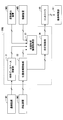
- FIG. 3 is a view showing a configuration example of a basic system of the shovel, and the mechanical power transmission line, the hydraulic oil line and the pilot line are respectively shown by a double line, a solid line and a broken line.
- the basic system of the shovel mainly includes an engine 11, a main pump 14, a pilot pump 15, a control valve 17, an operating device 26, a controller 30, an engine control unit (ECU) 74, and the like.
- ECU engine control unit
- the engine 11 is a driving source of a shovel, and is, for example, a diesel engine that operates to maintain a predetermined rotational speed.
- An output shaft of the engine 11 is connected to respective input shafts of the main pump 14 and the pilot pump 15.
- the main pump 14 is a hydraulic pump that supplies hydraulic fluid to the control valve 17 via a hydraulic fluid line 16, and is, for example, a swash plate type variable displacement hydraulic pump.
- the main pump 14 can adjust the stroke length of the piston by changing the angle of the swash plate (swash plate tilt angle), and can change the discharge amount, that is, the pump output.
- the swash plate tilt angle of the main pump 14 is controlled by the regulator 14a.
- the regulator 14a changes the swash plate tilt angle according to the change of the control current received by the attached solenoid valve (not shown). For example, when the control current increases, the regulator 14a increases the swash plate tilting angle to increase the discharge amount of the main pump 14. In addition, when the control current decreases, the regulator 14a reduces the swash plate tilt angle to reduce the discharge amount of the main pump 14.
- the pilot pump 15 is a hydraulic pump for supplying hydraulic fluid to various hydraulic control devices via the pilot line 25 and is, for example, a fixed displacement hydraulic pump.
- the control valve 17 is a set of hydraulic control valves that control a hydraulic system mounted on the shovel. In the present embodiment, a plurality of flow control valves are included.
- the control valve 17 selectively supplies, for example, the hydraulic oil supplied from the main pump 14 through the hydraulic oil line 16 to one or more hydraulic actuators in accordance with the operating direction and the operating amount of the operating device 26.
- the hydraulic actuator includes, for example, a boom cylinder 7, an arm cylinder 8, a bucket cylinder 9, a left traveling hydraulic motor 1A, a right traveling hydraulic motor 1B, and a turning hydraulic motor 2A.
- the left traveling hydraulic motor 1A, the right traveling hydraulic motor 1B, and the turning hydraulic motor 2A may be configured by electric motors.
- the operating device 26 is a device used by the operator for operating the hydraulic actuator, and includes a lever or a pedal.
- the operating device 26 receives the supply of hydraulic oil from the pilot pump 15 via the pilot line 25. Then, hydraulic fluid is supplied to the pilot port of the flow control valve corresponding to each of the hydraulic actuators through the pilot lines 25a, 25b.
- the pressure of the hydraulic oil supplied to the pilot port is a pressure corresponding to the operating direction and the operating amount of the operating device 26 corresponding to each of the hydraulic actuators.
- the controller 30 is a control device for controlling a shovel, and is configured of, for example, a computer including a CPU, a RAM, a ROM, and the like.
- the controller 30 executes programs corresponding to various functions to realize various functions.
- the various functions include the function of controlling the discharge amount of the main pump 14 by changing the magnitude of the control current to the solenoid valve of the regulator 14a.
- An engine control unit (ECU) 74 is configured to control the engine 11.
- the ECU 74 controls the number of rotations of the engine 11 based on, for example, a command from the controller 30.
- the operator sets the engine rotational speed using, for example, the engine rotational speed adjustment dial 75.
- the ECU 74 controls the fuel injection amount and the like so as to realize the set engine rotational speed.
- the engine rotation number adjustment dial 75 is a dial for adjusting the rotation number of the engine 11 and is provided in the cabin 10.
- the engine speed can be switched in five steps.
- the operator can switch the engine speed in five steps of Rmax, R4, R3, R2 and R1 by operating the engine speed adjustment dial 75.
- FIG. 3 shows a state where R4 is selected by the engine speed adjustment dial 75.
- the image display device 40 is a device for displaying various information, and is provided in the cabin 10.
- the image display device 40 includes an image display unit 41 and an input unit 42.
- the operator can view the image display unit 41 and confirm the operating condition or control information of the shovel.
- the operator can input various information to the controller 30 using the input unit 42.
- the image display device 40 is connected to the controller 30 via a communication network such as CAN or LIN.
- the image display device 40 may be connected to the controller 30 via a dedicated line.
- the image display device 40 includes a conversion processing unit 40a that generates an image for display.
- the conversion processing unit 40a generates a camera image for display based on the output of the imaging device M5 which is a device for acquiring the surface state of the feature.
- the imaging device M5 is, for example, a monocular camera connected to the image display device 40 via a dedicated line.
- the imaging device M5 may be a stereo camera, a distance image camera (distance image sensor), an infrared camera, an infrared thermography camera, or the like.
- the conversion processing unit 40 a may generate an image for display based on the output of the controller 30.
- the conversion processing unit 40a may be realized not as a function of the image display device 40 but as a function of the controller 30.
- the imaging device M5 is connected not to the image display device 40 but to the controller 30.
- Image display device 40 operates by receiving power supply from storage battery 70.
- the storage battery 70 is charged with the power generated by the alternator 11 a (generator) of the engine 11.
- the electric power of the storage battery 70 is supplied to the controller 30, the image display device 40, the electrical component 72 of the shovel, and the like.
- the starter 11 b is driven by the power from the storage battery 70 to start the engine 11.
- the ECU 74 transmits various data indicating the state of the engine 11 to the controller 30.
- Various data include, for example, data indicating the cooling water temperature output by the water temperature sensor 11c, data indicating the swash plate tilt angle of the main pump 14 output by the regulator 14a, and the discharge pressure of the main pump 14 output by the discharge pressure sensor 14b.
- the controller 30 can store data in the temporary storage unit 30a and can transmit the data to the image display device 40 when necessary.
- the external computing device 30E is a control device that performs various computations based on the output of at least one of the communication device M1, the positioning device M2, the posture detection device M3, the imaging device M5, etc., and outputs the computation result to the controller 30. .
- the external computing device 30E operates by receiving the supply of power from the storage battery 70.
- FIG. 4 is a view showing a configuration example of a hydraulic system mounted on a shovel.
- the hydraulic system mainly includes main pumps 14L and 14R, a pilot pump 15, a control valve 17, an operating device 26, a switching valve 50, and the like.
- the main pumps 14L, 14R correspond to the main pump 14 of FIG.
- the control valve 17 includes flow control valves 171 to 176 for controlling the flow of hydraulic fluid discharged by the main pumps 14L, 14R.
- the control valve 17 passes through the flow control valves 171 to 176, and among the boom cylinder 7, the arm cylinder 8, the bucket cylinder 9, the left traveling hydraulic motor 1A, the right traveling hydraulic motor 1B, and the turning hydraulic motor 2A.
- the hydraulic fluid discharged by the main pumps 14L, 14R is selectively supplied to one or more of the above.
- the operation content detection device 29 is configured to detect the content of the operation of the operation device 26 by the operator.
- the operation content detection device 29 includes operation pressure sensors 29a and 29b that detect the operation direction and the operation amount of the operation device 26 corresponding to each of the hydraulic actuators in the form of pressure.
- the operation content detection device 29 may be configured by another sensor other than the pressure sensor, such as a potentiometer.
- the main pumps 14L, 14R driven by the engine 11 circulate the hydraulic oil to the hydraulic oil tank through the center bypass lines 40L, 40R respectively.
- the center bypass line 40L is a hydraulic oil line passing through the flow control valves 171, 173 and 175 disposed in the control valve 17.
- the center bypass line 40 ⁇ / b> R is a hydraulic oil line passing through the flow control valves 172, 174 and 176 disposed in the control valve 17.
- the flow control valves 171, 172, and 173 are spool valves that control the flow rate and flow direction of hydraulic fluid flowing into and out of the left traveling hydraulic motor 1A, the right traveling hydraulic motor 1B, and the turning hydraulic motor 2A.
- the flow control valves 174, 175, and 176 are spool valves that control the flow rate and flow direction of hydraulic fluid flowing into and out of the bucket cylinder 9, the arm cylinder 8, and the boom cylinder 7.
- the left traveling hydraulic motor 1A and the right traveling hydraulic motor 1B are traveling hydraulic motors for driving the lower traveling body 1.
- the swash plate type variable displacement hydraulic motor is configured to be able to switch the traveling mode between a high speed and low torque high speed traveling mode and a low speed and high torque low speed traveling mode.
- the switching of the traveling mode is performed by a motor regulator attached to a traveling hydraulic motor.
- the motor regulator can switch the traveling mode of the traveling hydraulic motor according to at least one of a command from the controller 30, a traveling load (pressure of hydraulic fluid flowing through the traveling hydraulic motor), and the like.
- the swash plate tilt angle is small, and the displacement (motor volume) per one rotation of the hydraulic motor is small.
- the swash plate tilt angle is large and the motor volume is large.
- the switching valve 50 is a valve that switches communication / disconnection between the operating device 26 and the pilot ports of the flow control valves 171 to 176.
- the switching valve 50 is an electromagnetic valve that switches the valve position in accordance with a control command from the controller 30. Specifically, when the switching valve 50 receives a shutoff command from the controller 30, the communication between the controller device 26 and each pilot port is partially or completely shut off, and the switching valve 50 is operated when a communication command is received. Release the blocking between the device 26 and each pilot port.
- the switching valve 50 may be an electromagnetic proportional valve capable of flow control.
- FIG. 5 is a functional block diagram showing a configuration example of the external arithmetic device 30E.
- the external processing device 30E receives the outputs of the communication device M1, the positioning device M2, and the posture detection device M3, executes various calculations, and outputs the calculation results to the controller 30.
- the controller 30 outputs, for example, a control command according to the calculation result to the operation limiting unit E1.
- the operation restriction unit E1 is a functional element for restricting the movement of the shovel, and is, for example, a pressure reducing valve that adjusts a pilot pressure, or a switching valve that can shut off the flow of hydraulic fluid from the main pump 14 to the control valve 17 including.
- the switching valve 50 is employed as the operation limiting unit E1.
- the operation limiting unit E1 may include a warning output device that outputs a warning to the operator of the shovel.
- the warning output device is, for example, an audio output device or a warning lamp.
- the external arithmetic unit 30E mainly includes a terrain database update unit 31, a position coordinate update unit 32, a ground shape information acquisition unit 33, and a travel restriction unit 34.
- the terrain database update unit 31 is a functional element that updates a terrain database that systematically stores the terrain information of the work site so as to be referable.
- the terrain database updating unit 31 acquires terrain information of the work site through the communication device M1, for example, when the shovel is activated, and updates the terrain database.
- the topography database is stored in a non-volatile memory or the like. Terrain information of the work site is described, for example, by a three-dimensional terrain model based on the world positioning system.
- the position coordinate updating unit 32 is a functional element that updates the coordinates and the direction representing the current position of the shovel.
- the position coordinate updating unit 32 acquires the position coordinates and direction of the shovel in the world positioning system based on the output of the positioning device M2, and coordinates indicating the current position of the shovel stored in the non-volatile memory or the like. And update data on orientation.
- the position coordinate updating unit 32 may acquire the position coordinate and the direction of the shovel based on dead reckoning using an output of a gyro sensor, an acceleration sensor or the like.
- the ground shape information acquisition unit 33 is a functional element that acquires information on the current shape of the work target ground.
- the ground shape information acquisition unit 33 detects the terrain information updated by the terrain database update unit 31, the coordinates and direction indicating the current position of the shovel updated by the position coordinate update unit 32, and the posture detection device M3.
- Information on the current shape of the work target ground is acquired based on the past transition (operation history) of the posture of the excavation attachment. Therefore, the ground shape information acquisition unit 33 can acquire information on the change of the topography around the upper swing body 3 including the information on the change of the topography due to the excavation work.
- the operation history which is the transition of the posture of the excavation attachment, is, for example, boom angle ⁇ 1, arm angle ⁇ 2, bucket angle ⁇ 3, tilt angle ⁇ 4 around the Y axis of the shovel, tilt angle ⁇ 5 around the X axis of the shovel, etc. And at least one of the time series data stored in the volatile memory or the non-volatile memory.
- the ground shape information acquisition unit 33 may delete the operation history up to that point.
- the ground shape information acquisition unit 33 is based on the coordinates and direction indicating the current position of the shovel updated by the position coordinate update unit 32, and the past transition (operation history) of the posture of the excavation attachment detected by the posture detection device M3. Information on the current shape of the work target ground may be obtained.
- the travel limiting unit 34 is a functional element that limits travel of the shovel.
- the travel limiting unit 34 coordinates and indicates the current position of the shovel updated by the position coordinate updating unit 32, and information on the current shape of the work target ground acquired by the ground shape information acquisition unit 33.
- the movement of the undercarriage 1 is limited based on For example, when it is determined that the predetermined feature is present within a predetermined distance in the forward direction of the lower traveling body 1, the travel limiting unit 34 limits the forward movement of the lower traveling body 1 and the backward traveling direction of the lower traveling body 1 When it is determined that the predetermined feature is present within the predetermined distance, the reverse traveling of the lower traveling body 1 is limited.
- the predetermined feature is, for example, a feature that satisfies a predetermined condition among features such as a hole or a fill formed by an excavation operation.
- the predetermined feature is a hole having a depth greater than a predetermined depth, a hole having an inclination angle of a side surface (inclined surface) larger than a predetermined angle, an embankment having a height greater than a predetermined height, and an inclination angle of a side surface (inclined surface) Includes larger embankments etc.
- the posture of the shovel becomes extremely unstable if the lower traveling body 1 passes a predetermined feature.
- the forward direction and reverse direction of the undercarriage 1 are determined, for example, based on the output of the positioning device M2.
- the travel limiting unit 34 excludes holes having a side surface inclination angle of a predetermined angle or more as a predetermined feature and a hole whose inclination angle is less than a predetermined angle from the predetermined feature Do.
- a hole whose depth is equal to or greater than a predetermined depth may be set as a predetermined feature, and a hole whose depth is less than the predetermined depth may be excluded from the predetermined feature.
- the travel limiting unit 34 sets, for example, an embankment with an inclination angle of a side surface of a predetermined angle or more among the embankments formed in the excavation work as a predetermined feature, and an embankment with an inclination angle of less than the predetermined angle Exclude from things.
- the embankment whose height is equal to or more than a predetermined height may be set as a predetermined feature, and the embankment whose height is less than a predetermined height may be excluded from the predetermined features.
- the travel limitation of the shovel includes at least one of the limitation of the maximum moving speed of the undercarriage 1, the limitation of the maximum moving acceleration, the limitation of the maximum moving distance, and the prohibition of the movement.
- the travel limiting unit 34 when it is determined that the predetermined feature is present within the predetermined distance in the forward direction of the lower traveling body 1, the travel limiting unit 34 outputs the determination result to the controller 30.
- the controller 30 receiving the determination result outputs a shutoff command to the switching valve 50 as the operation limiting unit E1.
- the switching valve 50 that has received the shutoff command shuts off the communication between the traveling operation device as the operation device 26 and the right pilot port of each of the flow control valve 171 and the flow control valve 172 to inhibit the forward movement of the shovel.
- the travel operation device includes a travel lever and a travel pedal.
- the upper limit of the pilot pressure acting on the right pilot port of each of the flow control valve 171 and the flow control valve 172 may be lowered to limit the maximum forward speed.
- the forward movement of the shovel may be stopped when the distance to the predetermined feature becomes less than the predetermined value.
- the controller 30 may output a command to the motor regulator as the operation limiting unit E1, and may limit the moving speed of the lower traveling body 1 by fixing the traveling mode of the traveling hydraulic motor to the low speed traveling mode.
- the lower traveling body 1 includes a left crawler and a right crawler.
- the controller 30 may simultaneously restrict the movement of the left crawler and the right crawler, or may individually restrict them.
- the controller 30 can prevent the shovel from being stuck in the hole as the predetermined feature or running on the fill as the predetermined feature due to the operator's erroneous operation.
- the operator's erroneous operation includes a reverse operation performed with the intention to move the lower traveling body 1 forward and an advancing operation performed with the intention to move the lower traveling body 1 backward.
- the external calculation device 30E of FIG. 6 is different from the external calculation device 30E of FIG. 5 in that the ground shape information acquisition unit 33 can acquire information on the current shape of the work ground based on the output of the imaging device M5. , In all other respects. Therefore, the description of the common parts is omitted, and the different parts will be described in detail.
- the imaging device M5 may be attached to the excavation attachment or may be attached to the cabin 10. This is in order to be able to take an image of the surrounding terrain by turning along with the turning of the upper turning body 3.
- the imaging device M5 may be attached to a pole or the like installed at a work site, or may be attached to a flying object flying around the shovel.
- the flying object includes, for example, a multicopter or an airship.
- the ground shape information acquisition unit 33 can acquire information related to the current shape of the work target ground based on the distance image output by the imaging device M5, which is, for example, a stereo camera or a distance image camera.
- the imaging device M5 is attached to the excavation attachment
- the distance image is converted into a distance image based on the positioning device M2 (excavator) based on the relative positional relationship between the positioning device M2 and the imaging device M5.
- the imaging device M5 is attached to the pole
- the distance image is converted into a distance image based on the positioning device M2 (excavator) based on the previously measured attachment position (latitude, longitude, altitude) of the imaging device M5 Be done.
- the distance image is a distance image based on the output of the positioning device mounted on the flying object and the output of the positioning device M2 based on the positioning device M2 (excavator) Converted to
- the ground shape information acquisition unit 33 acquires information on the current shape of the work target ground based on the output of a distance measuring device which is a device for acquiring the surface state of a feature such as a lidar or a laser range finder. Good.
- the distance measuring device may be attached to the digging attachment as in the case of the imaging device M5, or may be attached to a pole or the like installed at the work site, and an aircraft flying around the shovel It may be attached to The conversion from the distance information measured by the distance measuring device to the distance information based on the shovel is performed in the same manner as described above.
- the imaging device M5 may be independent of the shovel.
- the controller 30 may acquire terrain information output by the imaging device M5 via the communication device M1.
- the imaging device M5 is attached to a multi-copter for aerial photography or a steel tower installed at a work site, and acquires topographical information of the work site based on an image of the work site viewed from above Good.
- the imaging device M5 may be an imaging device M5 provided in another shovel.
- the imaging device M5 may transmit data directly to the shovel, or may transmit data to the shovel via the management device.
- the management apparatus is, for example, a computer installed in an external facility such as a management center.
- the terrain database updating unit 31 acquires terrain information from the external imaging device M5 or terrain information from the management device through the communication device M1. . Then, the terrain database updating unit 31 updates the terrain information around the shovel based on the acquired terrain information, and the ground shape information acquiring unit 33 changes the terrain based on the terrain information updated by the terrain database updating unit 31. You can get information about
- the controller 30 can more reliably prevent the shovel from being stuck in the hole as the predetermined feature or running on the fill as the predetermined feature due to the operator's erroneous operation.
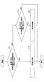
- FIG. 7 is a flowchart of the travel restriction process.
- the controller 30 repeatedly executes this traveling restriction process at a predetermined control cycle.
- the ground shape information acquisition unit 33 of the controller 30 acquires information on the current shape of the work target ground in parallel with the travel restriction process.
- the ground shape information acquisition unit 33 detects the terrain information updated by the terrain database update unit 31, the coordinates and direction indicating the current position of the shovel updated by the position coordinate update unit 32, and the posture detection device M3.
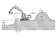
- FIGS. 8A-8C are cross-sectional views of the work target ground, showing how the shapes change in the order of FIG. 8A, FIG. 8B and FIG. 8C.
- the dashed-dotted line in each of FIGS. 8A-8C represents the target topography (the topography to be realized by the digging operation).
- the shovel acquires data on the target topography through the communication device M1.
- the travel limiting unit 34 of the controller 30 determines whether a predetermined feature exists within a predetermined distance in the forward direction (step ST1).
- the predetermined feature is a hole having a depth greater than the predetermined depth TH1 and a side inclination angle greater than the predetermined angle TH2, and a height higher than the predetermined height TH3, and an inclination angle of the side greater than the predetermined angle TH4. Includes large fill.
- the travel limiting unit 34 grasps the shape of the predetermined feature and the distance to the predetermined feature, and determines whether or not the predetermined feature is present within the predetermined distance in the forward direction.
- the predetermined distance in the forward direction is, for example, the horizontal distance from the front end of the undercarriage 1.
- the travel limiting unit 34 limits the forward (step ST2).
- the travel limiting unit 34 determines whether the predetermined feature is present within the predetermined distance in the reverse direction (Ste ST3).
- the travel limiting unit 34 limits the reverse (step ST4).
- the predetermined distance in the reverse direction is, for example, the horizontal distance from the rear end of the lower traveling body 1.
- the travel limiting unit 34 Ends the current travel restriction process without restricting either forward or reverse.
- the travel limiting unit 34 determines that the predetermined feature does not exist within the predetermined distance in the forward direction, and then determines whether the predetermined feature exists within the predetermined distance in the reverse direction. There is. However, after determining that the predetermined feature does not exist within the predetermined distance in the reverse direction, the travel limiting unit 34 may determine whether the predetermined feature exists within the predetermined distance in the forward direction. Alternatively, two determinations may be performed in parallel.
- the travel restriction unit 34 has predetermined features in the forward direction. It determines that it does not exist.
- This hole has a side surface with an inclination angle ⁇ 1 larger than the predetermined angle TH2, but is not determined to be the predetermined feature because the depth D1 is less than the predetermined depth TH1. Therefore, the travel limiting unit 34 does not limit the forward travel.
- the hole having the depth D1 may be determined to be a predetermined feature because it has a side surface having an inclination angle ⁇ 1 larger than the predetermined angle TH2. In this case, the travel limiting unit 34 limits the forward travel.
- the travel limiting unit 34 determines that the predetermined feature does not exist in the reverse direction. .
- this embankment has the side surface of inclination angle ⁇ 1 larger than predetermined angle TH4, since height H1 is less than predetermined height TH3, it is not determined as a predetermined feature. Therefore, the travel limiting unit 34 does not limit reverse travel.
- the embankment of the height H1 may be determined to be a predetermined feature because it has a side surface of the inclination angle ⁇ 1 larger than the predetermined angle TH4. In this case, the travel limiting unit 34 limits reverse travel.
- the travel limiting unit 34 determines that the predetermined feature does not exist in the forward direction. Further, within the predetermined distance R in the reverse direction, the embankment continuing to the height H2 which is the predetermined height TH3 or more exists, but since the inclination angle ⁇ 2 of the side is less than the predetermined angle TH4, the travel limiting portion 34 It is determined that a predetermined feature does not exist behind. Therefore, the travel limiting unit 34 does not limit either forward or reverse.
- the travel limiting unit 34 may determine that the hole existing in the predetermined distance F in the forward direction is the predetermined feature because the hole continues to the depth D2. Also, the embankment may be determined as the predetermined feature because the embankment existing within the predetermined distance R in the reverse direction continues up to the height H2.
- the ground shape information acquisition unit 33 sets a range of a distance L equal to the depth D3 of the hole from the edge of the hole determined to be a predetermined feature as the limit range, and travels the lower part so that the shovel does not enter the limit range.
- the movement of the body 1 may be restricted.
- the ground shape information acquisition unit 33 can suppress the approach of the shovel from the predetermined feature and can further enhance the safety.
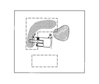
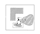
- FIGS. 9A to 9C are top views of the work site, showing how the digging operation proceeds in the order of FIGS. 9A, 9B and 9C.
- the dashed dotted line in each of FIGS. 9A to 9C represents the position of the hole that constitutes the target topography.
- the dot pattern represents the position of a hole as a predetermined feature.
- the hatching pattern represents the position of the fill as a predetermined feature.
- FIG. 9A shows the state of the work site before the digging operation is performed.
- An alternate long and short dash line indicates that a hole is to be formed in two places.
- the travel limiting unit 34 does not limit traveling of the shovel.
- FIG. 9B shows the state of the work site when the shovel is digging the first hole of the two holes.
- the dot pattern represents that a hole as a predetermined feature is formed within the range corresponding to the first hole.
- the hatching pattern indicates that the earth and sand excavated to form the first hole has formed an embankment as a predetermined feature.
- the travel limiting unit 34 limits the forward movement of the shovel. This is because a hole as a predetermined feature exists within a predetermined distance F in the forward direction of the lower traveling body 1.
- the travel limiting unit 34 does not limit the reverse travel of the shovel. This is because the predetermined feature is not present within the predetermined distance R in the reverse traveling direction of the lower traveling body 1.
- FIG. 9C represents the state of the work site when the shovel is drilling a second hole after completing the formation of the first of the two holes.
- the dot pattern represents that a hole as a predetermined feature is formed in the range corresponding to the first hole and in the range corresponding to the second hole.
- the hatching pattern indicates that the earth and sand excavated to form the first hole and the second hole form a deposit as a predetermined feature.
- the travel limiting unit 34 limits the reverse travel of the shovel. This is because a hole (second hole) as a predetermined feature exists within a predetermined distance R in the reverse traveling direction of the lower traveling body 1.
- the travel limiting unit 34 does not limit the forward movement of the shovel. This is because the predetermined feature is not present within the predetermined distance F in the forward direction of the lower traveling body 1.
- the controller 30 restricts the movement of the undercarriage 1 when the predetermined feature is present within the predetermined distance in the movement direction. Therefore, it is possible to prevent the shovel from falling in the hole excavated by the shovel and preventing the shovel from riding on the embankment made by the shovel.
- This limitation is particularly effective in a situation where the operator causes the undercarriage 1 to move in the opposite direction to the intended direction. Such a situation occurs, for example, when the operator concentrates too much on the operation of the attachment and misinterprets the forward direction of the lower traveling vehicle 1 as the reverse direction. However, it is also effective when the operator advances the lower traveling body 1 in the intended direction. This is because the predetermined features such as the holes and the fillings are difficult to see from the cabin 10, and it is difficult for the operator to notice the existence or to easily forget the existence.
- the shovel according to the embodiment of the present invention is configured such that the controller 30 restricts the movement of the lower traveling body 1 based on the information on the topography of the upper swing body 3.
- the shovel is configured such that the controller 30 restricts the movement of the undercarriage 1 based on the information on the change in topography around the upper swing body 3. Therefore, the shovel according to the embodiment of the present invention is, for example, stuck in a hole excavated by its own machine or another machine, or runs over an embankment made by its own machine or another machine, resulting in an unstable state of its own machine. Can be prevented in advance.
- the controller 30 desirably limits the movement of the undercarriage 1 based on the information on the change in topography due to the digging operation.
- the movement of the undercarriage 1 is limited based on the information on the change in topography due to the excavation work of the own aircraft. Therefore, the shovel mounted with the controller 30 can prevent the self-machine from becoming unstable due to being stuck in the hole excavated by the self-machine or riding on the embankment made by the self-machine.
- the controller 30 desirably acquires information on the change in topography due to the digging operation based on the operation history of the attachment including the detection value of the posture detection device M3. Therefore, the shovel mounted with the controller 30 can reliably and accurately acquire information on a hole excavated by the own machine, information on a deposit made by the own machine, and the like.
- the controller 30 is an upper part based on an output of a device (for example, an imaging device M5 or a distance measuring device) for acquiring the surface state of a feature or a device (for example, a posture detection device M3) for acquiring a locus of movement of an attachment.
- a device for example, an imaging device M5 or a distance measuring device
- a device for example, a posture detection device M3
- a device for example, an imaging device M5 or a distance measuring device for acquiring the surface state of a feature or a device (for example, a posture detection device M3) for acquiring a locus of movement of an attachment is desirably attached to the attachment There is. Therefore, a device (for example, an imaging device M5 or a distance measuring device) for acquiring the surface state of a feature or a device for acquiring a locus of movement of an attachment (for example, a posture detection device M3) Since the imaging direction or the measurement direction or the digging position changes according to, surrounding terrain can be imaged or measured over a wide range or can be derived.
- the undercarriage 1 is typically driven by a variable displacement hydraulic motor.
- the controller 30 can restrict the movement of the lower traveling body 1 by fixing the traveling mode of the hydraulic motor to the low speed traveling mode, that is, by not switching to the high speed traveling mode. Therefore, the controller 30 can restrict the movement of the undercarriage 1 simply and quickly.
- the controller 30 desirably limits at least one of the moving direction and the moving speed of the undercarriage 1. Therefore, the controller 30 can prevent the lower traveling body 1 from invading the predetermined feature without restricting the movement of the lower traveling body 1 in the direction away from the predetermined feature.
- the controller 30 may set a range of a predetermined distance from the predetermined feature as the limit range. With this configuration, the controller 30 can more reliably prevent the shovel from approaching the predetermined feature, and can further enhance the safety.
- the controller 30 may be configured to acquire information on the topography of the periphery of the upper swing body 3 from the imaging device M5 outside the shovel. With this configuration, the controller 30 can more easily acquire the work site terrain information.
- the external computing device 30E may be integrated into the controller 30. Further, the external computing device 30E may not be mounted on a shovel.
- the external computing device 30E may be provided in an external management facility such as a management center.
- the external computing device 30E may receive data acquired by at least one of the positioning device M2, the posture detection device M3, the imaging device M5, etc. via the network, and may calculate information related to topography, such as finished information . And you may transmit the information regarding the calculated topography to a shovel.
- the shovel may limit the movement of the undercarriage 1 based on the received information on the topography.
- the data acquired by the positioning device and the imaging device mounted on the aircraft may be transmitted from the aircraft to the external computing device E.
- the external computing device E may calculate information on the terrain based on the received data, and transmit the information on the terrain to the shovel.
- the vehicle may calculate the information on the terrain and transmit the information on the terrain directly to the shovel.
- Communication device M2 ... Positioning device M3 ... Posture detection device M3 a ... Boom angle sensor M3 b ... Arm angle sensor M3 c Bucket angle sensor M3d ⁇ ⁇ ⁇ vehicle body inclination sensor M5 ⁇ ⁇ ⁇ imaging apparatus
Abstract
This excavator comprises a lower traveling body (1), an upper turning body (3) that is mounted on the lower traveling body (1) and comprises an attachment, and a controller (30) that is mounted on the upper turning body (3). The controller (30) restricts the lower traveling body (1) movement on the basis of information pertaining to changes in the topography around the upper turning body (3). The controller (30), for example, restricts the lower traveling body (1) movement on the basis of information pertaining to the topography caused by the excavation work.
Description
本開示は、下部走行体を備えたショベルに関する。
The present disclosure relates to a shovel provided with a lower traveling body.
従来、上部旋回体に取り付けられたカメラが撮像したステレオペア画像に基づいて上部旋回体の周辺の地形を計測する計測装置を備えたショベルが知られている(特許文献1参照。)。この構成により、計測装置は、作業現場の地形データをリアルタイムに生成し且つ表示できる。
DESCRIPTION OF RELATED ART Conventionally, the shovel provided with the measuring device which measures the topography around a top turning body based on the stereo pair image which the camera attached to the top turning body imaged (refer patent document 1). With this configuration, the measuring device can generate and display the topography data of the work site in real time.
ところで、ショベルの操作者は、掘削作業を行うために走行操作、旋回操作及びアタッチメント操作を繰り返していると、下部走行体の向きを失念してしまう場合がある。そして、意図した方向とは逆の方向に下部走行体を移動させてしまう場合がある。
By the way, the operator of the shovel may forget the direction of the lower traveling body when the traveling operation, the turning operation, and the attachment operation are repeated in order to perform the digging operation. Then, the lower traveling body may be moved in the opposite direction to the intended direction.
このような場合であっても、上述の計測装置は、ステレオペア画像に基づいて地形データを生成し且つ表示するのみであるため、ショベルの移動方向に穴がある場合であっても、ショベルの移動を停止させることができない。その結果、ショベルの機体を不安定な状態にしてしまう場合がある。
Even in such a case, the above-described measuring device only generates and displays the terrain data based on the stereo pair image, so even if there is a hole in the moving direction of the shovel, I can not stop moving. As a result, the body of the shovel may be unstable.
上述に鑑み、機体が不安定な状態になるのを未然に防止できるショベルを提供することが望まれる。
In view of the above, it is desirable to provide a shovel that can prevent the machine from becoming unstable.
本発明の実施例に係るショベルは、下部走行体と、前記下部走行体に搭載される、アタッチメントを備えた上部旋回体と、前記上部旋回体に搭載される制御装置と、を備え、前記制御装置は、前記上部旋回体の周辺の地形に関する情報に基づいて前記下部走行体の動きを制限する。
A shovel according to an embodiment of the present invention includes a lower traveling body, an upper revolving superstructure equipped with an attachment mounted on the lower traveling body, and a control device installed on the upper revolving superstructure. The device limits the movement of the undercarriage based on information about the terrain around the upper slewing body.
上述の手段により、機体が不安定な状態になるのを未然に防止できるショベルが提供される。
According to the above-described means, a shovel is provided that can prevent the vehicle from becoming unstable.
最初に、図1を参照し、本発明の実施例に係る建設機械としてのショベル(掘削機)について説明する。図1は、本発明の実施例に係るショベルの側面図である。ショベルの下部走行体1には旋回機構2を介して上部旋回体3が搭載されている。上部旋回体3にはブーム4が取り付けられている。ブーム4の先端にはアーム5が取り付けられ、アーム5の先端にはバケット6が取り付けられている。作業要素としてのブーム4、アーム5及びバケット6は、アタッチメントの一例である掘削アタッチメントを構成する。ブーム4は、ブームシリンダ7により駆動される。アーム5は、アームシリンダ8により駆動される。バケット6は、バケットシリンダ9により駆動される。上部旋回体3にはキャビン10が設けられ、且つ、エンジン11等の動力源が搭載されている。また、上部旋回体3には通信装置M1、測位装置M2及び姿勢検出装置M3が取り付けられている。
First, a shovel (excavator) as a construction machine according to an embodiment of the present invention will be described with reference to FIG. FIG. 1 is a side view of a shovel according to an embodiment of the present invention. An upper swing body 3 is mounted on the lower traveling body 1 of the shovel via a turning mechanism 2. A boom 4 is attached to the upper swing body 3. An arm 5 is attached to the tip of the boom 4, and a bucket 6 is attached to the tip of the arm 5. The boom 4 as a working element, the arm 5 and the bucket 6 constitute a digging attachment which is an example of an attachment. The boom 4 is driven by a boom cylinder 7. The arm 5 is driven by an arm cylinder 8. The bucket 6 is driven by a bucket cylinder 9. A cabin 10 is provided in the upper revolving superstructure 3 and a power source such as an engine 11 is mounted. Further, a communication device M1, a positioning device M2, and a posture detection device M3 are attached to the upper swing body 3.
通信装置M1は、ショベルと外部との間の通信を制御するように構成されている。本実施例では、通信装置M1は、GNSS(Global Navigation Satellite System)測量システムとショベルとの間の無線通信を制御する。具体的には、通信装置M1は、例えば1日1回の頻度で、ショベルの作業を開始する際に作業現場の地形情報を取得する。GNSS測量システムは、例えばネットワーク型RTK-GNSS測位方式を採用する。
The communication device M1 is configured to control communication between the shovel and the outside. In the present embodiment, the communication device M1 controls wireless communication between a Global Navigation Satellite System (GNSS) surveying system and a shovel. Specifically, the communication device M1 acquires topographical information of the work site when starting the work of the shovel, for example, once a day. The GNSS surveying system adopts, for example, a network type RTK-GNSS positioning method.
測位装置M2は、ショベルの位置を測定するように構成されている。測位装置M2は、ショベルの向きを測定するように構成されていてもよい。本実施例では、測位装置M2は、電子コンパスを組み込んだGNSS受信機であり、上部旋回体3に取り付けられている。そして、ショベルの存在位置の緯度、経度、高度を測定し、且つ、ショベル(上部旋回体3)の向きを測定する。測位装置M2は、下部走行体1に対する上部旋回体3の旋回角度を検出する旋回角度検出装置を含んでいてもよい。この構成により、測位装置M2は、ショベル(上部旋回体3)の向きから下部走行体1の向きを測定できる。但し、下部走行体1の向きは、別のGNSS受信機に基づいて測定されてもよい。
The positioning device M2 is configured to measure the position of the shovel. The positioning device M2 may be configured to measure the direction of the shovel. In the present embodiment, the positioning device M2 is a GNSS receiver incorporating an electronic compass, and is attached to the upper swing body 3. Then, the latitude, longitude, and altitude of the existing position of the shovel are measured, and the direction of the shovel (the upper swing body 3) is measured. The positioning device M2 may include a turning angle detection device that detects the turning angle of the upper swing body 3 with respect to the lower traveling body 1. With this configuration, the positioning device M2 can measure the direction of the lower traveling body 1 from the direction of the shovel (the upper swing body 3). However, the orientation of the undercarriage 1 may be measured based on another GNSS receiver.
姿勢検出装置M3は、アタッチメントの姿勢を検出するように構成されている。姿勢検出装置M3は、例えば、操作に応じたアタッチメントの動きの軌跡を取得できる。本実施例では、姿勢検出装置M3は、掘削アタッチメントの姿勢を検出する。
The posture detection device M3 is configured to detect the posture of the attachment. The posture detection device M3 can acquire, for example, the trajectory of the movement of the attachment according to the operation. In the present embodiment, the posture detection device M3 detects the posture of the digging attachment.
図2は、図1のショベルに搭載される姿勢検出装置M3を構成する各種センサの構成例を示すショベルの側面図である。具体的には、姿勢検出装置M3は、ブーム角度センサM3a、アーム角度センサM3b、バケット角度センサM3c及び車体傾斜センサM3dを含む。
FIG. 2 is a side view of the shovel showing a configuration example of various sensors constituting the posture detection device M3 mounted on the shovel of FIG. Specifically, the posture detection device M3 includes a boom angle sensor M3a, an arm angle sensor M3b, a bucket angle sensor M3c, and a vehicle body inclination sensor M3d.
ブーム角度センサM3aは、ブーム角度θ1を取得するように構成されている。ブーム角度θ1は、例えば、XZ平面において、ブームフートピン位置P1とアーム連結ピン位置P2とを結ぶ線分の水平線に対する角度である。
The boom angle sensor M3a is configured to acquire the boom angle θ1. The boom angle θ1 is, for example, an angle with respect to a horizontal line of a line connecting the boom foot pin position P1 and the arm connecting pin position P2 in the XZ plane.
アーム角度センサM3bは、アーム角度θ2を取得するように構成されている。アーム角度θ2は、例えば、XZ平面において、アーム連結ピン位置P2とバケット連結ピン位置P3とを結ぶ線分の水平線に対する角度である。
The arm angle sensor M3b is configured to acquire an arm angle θ2. The arm angle θ2 is, for example, an angle with respect to a horizontal line of a line connecting the arm connection pin position P2 and the bucket connection pin position P3 in the XZ plane.
バケット角度センサM3cは、バケット角度θ3を取得するように構成されている。バケット角度θ3は、例えば、XZ平面において、バケット連結ピン位置P3とバケット爪先位置P4とを結ぶ線分の水平線に対する角度である。
The bucket angle sensor M3c is configured to acquire a bucket angle θ3. The bucket angle θ3 is, for example, an angle with respect to a horizontal line of a line connecting the bucket connecting pin position P3 and the bucket tip position P4 in the XZ plane.
本実施例では、ブーム角度センサM3aは、加速度センサとジャイロセンサの組み合わせで構成されている。但し、ブームフートピンの回転角度を検出する回転角度センサ、ブームシリンダ7のストローク量を検出するストロークセンサ、又は、ブーム4の傾斜角度を検出する傾斜センサ等で構成されていてもよい。アーム角度センサM3b及びバケット角度センサM3cについても同様である。
In the present embodiment, the boom angle sensor M3a is configured by a combination of an acceleration sensor and a gyro sensor. However, a rotation angle sensor for detecting the rotation angle of the boom foot pin, a stroke sensor for detecting the stroke amount of the boom cylinder 7, or an inclination sensor for detecting the inclination angle of the boom 4 may be used. The same applies to the arm angle sensor M3b and the bucket angle sensor M3c.
車体傾斜センサM3dは、ショベルのY軸回りの傾斜角θ4、及び、ショベルのX軸回りの傾斜角θ5(図示せず。)を取得するように構成されている。車体傾斜センサM3dは、例えば2軸傾斜(加速度)センサ又は3軸傾斜(加速度)センサ等を含む。図2のXY平面は水平面である。
The vehicle body inclination sensor M3d is configured to acquire an inclination angle θ4 around the Y axis of the shovel and an inclination angle θ5 (not shown) around the X axis of the shovel. The vehicle body inclination sensor M3d includes, for example, a two-axis inclination (acceleration) sensor or a three-axis inclination (acceleration) sensor. The XY plane in FIG. 2 is a horizontal plane.
次に、図3を参照してショベルの基本システムについて説明する。図3は、ショベルの基本システムの構成例を示す図であり、機械的動力伝達ライン、作動油ライン、パイロットラインをそれぞれ二重線、実線、破線で示す。ショベルの基本システムは、主に、エンジン11、メインポンプ14、パイロットポンプ15、コントロールバルブ17、操作装置26、コントローラ30及びエンジン制御装置(ECU)74等を含む。
Next, the basic system of the shovel will be described with reference to FIG. FIG. 3 is a view showing a configuration example of a basic system of the shovel, and the mechanical power transmission line, the hydraulic oil line and the pilot line are respectively shown by a double line, a solid line and a broken line. The basic system of the shovel mainly includes an engine 11, a main pump 14, a pilot pump 15, a control valve 17, an operating device 26, a controller 30, an engine control unit (ECU) 74, and the like.
エンジン11はショベルの駆動源であり、例えば、所定の回転数を維持するように動作するディーゼルエンジンである。エンジン11の出力軸はメインポンプ14及びパイロットポンプ15のそれぞれの入力軸に接続されている。
The engine 11 is a driving source of a shovel, and is, for example, a diesel engine that operates to maintain a predetermined rotational speed. An output shaft of the engine 11 is connected to respective input shafts of the main pump 14 and the pilot pump 15.
メインポンプ14は、作動油ライン16を介して作動油をコントロールバルブ17に供給する油圧ポンプであり、例えば、斜板式可変容量型油圧ポンプである。メインポンプ14は、斜板の角度(斜板傾転角)を変更することでピストンのストローク長を調整し、吐出量、すなわち、ポンプ出力を変化させることができる。メインポンプ14の斜板傾転角は、レギュレータ14aにより制御される。レギュレータ14aは、付属の電磁弁(不図示)が受ける制御電流の変化に応じて斜板傾転角を変化させる。例えば、制御電流が増加すると、レギュレータ14aは、斜板傾転角を大きくして、メインポンプ14の吐出量を増大させる。また、制御電流が減少すると、レギュレータ14aは、斜板傾転角を小さくして、メインポンプ14の吐出量を低減させる。
The main pump 14 is a hydraulic pump that supplies hydraulic fluid to the control valve 17 via a hydraulic fluid line 16, and is, for example, a swash plate type variable displacement hydraulic pump. The main pump 14 can adjust the stroke length of the piston by changing the angle of the swash plate (swash plate tilt angle), and can change the discharge amount, that is, the pump output. The swash plate tilt angle of the main pump 14 is controlled by the regulator 14a. The regulator 14a changes the swash plate tilt angle according to the change of the control current received by the attached solenoid valve (not shown). For example, when the control current increases, the regulator 14a increases the swash plate tilting angle to increase the discharge amount of the main pump 14. In addition, when the control current decreases, the regulator 14a reduces the swash plate tilt angle to reduce the discharge amount of the main pump 14.
パイロットポンプ15は、パイロットライン25を介して各種油圧制御機器に作動油を供給するための油圧ポンプであり、例えば、固定容量型油圧ポンプである。
The pilot pump 15 is a hydraulic pump for supplying hydraulic fluid to various hydraulic control devices via the pilot line 25 and is, for example, a fixed displacement hydraulic pump.
コントロールバルブ17は、ショベルに搭載されている油圧システムを制御する1組の油圧制御弁である。本実施例では、複数の流量制御弁を含む。コントロールバルブ17は、例えば、メインポンプ14から作動油ライン16を通じて供給された作動油を、操作装置26の操作方向及び操作量に応じて、一又は複数の油圧アクチュエータに選択的に供給する。油圧アクチュエータは、例えば、ブームシリンダ7、アームシリンダ8、バケットシリンダ9、左走行用油圧モータ1A、右走行用油圧モータ1B及び旋回用油圧モータ2Aを含む。左走行用油圧モータ1A、右走行用油圧モータ1B及び旋回用油圧モータ2Aは、電動モータで構成されていてもよい。
The control valve 17 is a set of hydraulic control valves that control a hydraulic system mounted on the shovel. In the present embodiment, a plurality of flow control valves are included. The control valve 17 selectively supplies, for example, the hydraulic oil supplied from the main pump 14 through the hydraulic oil line 16 to one or more hydraulic actuators in accordance with the operating direction and the operating amount of the operating device 26. The hydraulic actuator includes, for example, a boom cylinder 7, an arm cylinder 8, a bucket cylinder 9, a left traveling hydraulic motor 1A, a right traveling hydraulic motor 1B, and a turning hydraulic motor 2A. The left traveling hydraulic motor 1A, the right traveling hydraulic motor 1B, and the turning hydraulic motor 2A may be configured by electric motors.
操作装置26は、操作者が油圧アクチュエータの操作のために用いる装置であり、レバー又はペダル等を含む。本実施例では、操作装置26は、パイロットライン25を介してパイロットポンプ15から作動油の供給を受ける。そして、パイロットライン25a、25bを通じて、油圧アクチュエータのそれぞれに対応する流量制御弁のパイロットポートに作動油を供給する。パイロットポートに供給される作動油の圧力は、油圧アクチュエータのそれぞれに対応する操作装置26の操作方向及び操作量に応じた圧力とされる。
The operating device 26 is a device used by the operator for operating the hydraulic actuator, and includes a lever or a pedal. In the present embodiment, the operating device 26 receives the supply of hydraulic oil from the pilot pump 15 via the pilot line 25. Then, hydraulic fluid is supplied to the pilot port of the flow control valve corresponding to each of the hydraulic actuators through the pilot lines 25a, 25b. The pressure of the hydraulic oil supplied to the pilot port is a pressure corresponding to the operating direction and the operating amount of the operating device 26 corresponding to each of the hydraulic actuators.
コントローラ30は、ショベルを制御するための制御装置であり、例えば、CPU、RAM及びROM等を備えたコンピュータで構成される。コントローラ30は、各種機能に対応するプログラムを実行して各種機能を実現する。各種機能は、レギュレータ14aの電磁弁に対する制御電流の大きさを変化させることでメインポンプ14の吐出量を制御する機能を含む。
The controller 30 is a control device for controlling a shovel, and is configured of, for example, a computer including a CPU, a RAM, a ROM, and the like. The controller 30 executes programs corresponding to various functions to realize various functions. The various functions include the function of controlling the discharge amount of the main pump 14 by changing the magnitude of the control current to the solenoid valve of the regulator 14a.
エンジン制御装置(ECU)74は、エンジン11を制御するように構成されている。ECU74は、例えば、コントローラ30からの指令に基づいてエンジン11の回転数を制御する。操作者は、例えば、エンジン回転数調整ダイヤル75を用いてエンジン回転数を設定する。ECU74は、設定されたエンジン回転数を実現するように燃料噴射量等を制御する。
An engine control unit (ECU) 74 is configured to control the engine 11. The ECU 74 controls the number of rotations of the engine 11 based on, for example, a command from the controller 30. The operator sets the engine rotational speed using, for example, the engine rotational speed adjustment dial 75. The ECU 74 controls the fuel injection amount and the like so as to realize the set engine rotational speed.
エンジン回転数調整ダイヤル75は、エンジン11の回転数を調整するためのダイヤルであり、キャビン10内に設けられている。本実施例ではエンジン回転数を5段階で切り換えできるように構成されている。操作者は、エンジン回転数調整ダイヤル75を操作することで、Rmax、R4、R3、R2及びR1の5段階でエンジン回転数を切り換えることができる。図3は、エンジン回転数調整ダイヤル75でR4が選択された状態を示す。
The engine rotation number adjustment dial 75 is a dial for adjusting the rotation number of the engine 11 and is provided in the cabin 10. In this embodiment, the engine speed can be switched in five steps. The operator can switch the engine speed in five steps of Rmax, R4, R3, R2 and R1 by operating the engine speed adjustment dial 75. FIG. 3 shows a state where R4 is selected by the engine speed adjustment dial 75.
画像表示装置40は、各種情報を表示するための装置であり、キャビン10内に設けられている。本実施例では、画像表示装置40は、画像表示部41及び入力部42を含む。操作者は、画像表示部41を見てショベルの運転状況又は制御情報等を確認できる。また、操作者は、入力部42を利用して各種情報をコントローラ30に入力できる。画像表示装置40は、CAN又はLIN等の通信ネットワークを介してコントローラ30に接続される。但し、画像表示装置40は、専用線を介してコントローラ30に接続されてもよい。
The image display device 40 is a device for displaying various information, and is provided in the cabin 10. In the present embodiment, the image display device 40 includes an image display unit 41 and an input unit 42. The operator can view the image display unit 41 and confirm the operating condition or control information of the shovel. Also, the operator can input various information to the controller 30 using the input unit 42. The image display device 40 is connected to the controller 30 via a communication network such as CAN or LIN. However, the image display device 40 may be connected to the controller 30 via a dedicated line.
画像表示装置40は、表示用の画像を生成する変換処理部40aを含む。本実施例では、変換処理部40aは、地物の表面状態を取得する装置である撮像装置M5の出力に基づいて表示用のカメラ画像を生成する。撮像装置M5は、例えば専用線を介して画像表示装置40に接続される単眼カメラである。撮像装置M5は、ステレオカメラ、距離画像カメラ(距離画像センサ)、赤外線カメラ又は赤外線サーモグラフィカメラ等であってもよい。変換処理部40aは、コントローラ30の出力に基づいて表示用の画像を生成してもよい。
The image display device 40 includes a conversion processing unit 40a that generates an image for display. In the present embodiment, the conversion processing unit 40a generates a camera image for display based on the output of the imaging device M5 which is a device for acquiring the surface state of the feature. The imaging device M5 is, for example, a monocular camera connected to the image display device 40 via a dedicated line. The imaging device M5 may be a stereo camera, a distance image camera (distance image sensor), an infrared camera, an infrared thermography camera, or the like. The conversion processing unit 40 a may generate an image for display based on the output of the controller 30.
変換処理部40aは、画像表示装置40が有する機能としてではなく、コントローラ30が有する機能として実現されてもよい。この場合、撮像装置M5は、画像表示装置40ではなく、コントローラ30に接続される。
The conversion processing unit 40a may be realized not as a function of the image display device 40 but as a function of the controller 30. In this case, the imaging device M5 is connected not to the image display device 40 but to the controller 30.
画像表示装置40は、蓄電池70から電力の供給を受けて動作する。蓄電池70はエンジン11のオルタネータ11a(発電機)で発電した電力で充電される。蓄電池70の電力は、コントローラ30、画像表示装置40及びショベルの電装品72等に供給される。スタータ11bは、蓄電池70からの電力で駆動され、エンジン11を始動する。
Image display device 40 operates by receiving power supply from storage battery 70. The storage battery 70 is charged with the power generated by the alternator 11 a (generator) of the engine 11. The electric power of the storage battery 70 is supplied to the controller 30, the image display device 40, the electrical component 72 of the shovel, and the like. The starter 11 b is driven by the power from the storage battery 70 to start the engine 11.
ECU74は、エンジン11の状態を示す各種データをコントローラ30に送信する。各種データは、例えば、水温センサ11cが出力する冷却水温を示すデータ、レギュレータ14aが出力するメインポンプ14の斜板傾転角を示すデータ、吐出圧センサ14bが出力するメインポンプ14の吐出圧を示すデータ、油温センサ14cが出力する作動油の温度を示すデータ、操作圧センサ29a、29bが出力するパイロット圧を示すデータ、及び、エンジン回転数調整ダイヤル75が出力するエンジン回転数の設定状態を示すデータ等を含む。コントローラ30は一時記憶部30aにデータを蓄積しておき、必要なときに画像表示装置40に送信できる。
The ECU 74 transmits various data indicating the state of the engine 11 to the controller 30. Various data include, for example, data indicating the cooling water temperature output by the water temperature sensor 11c, data indicating the swash plate tilt angle of the main pump 14 output by the regulator 14a, and the discharge pressure of the main pump 14 output by the discharge pressure sensor 14b. Data indicating the temperature, data indicating the temperature of the hydraulic fluid output by the oil temperature sensor 14c, data indicating the pilot pressure output by the operating pressure sensors 29a and 29b, and the setting state of the engine rotational speed output by the engine rotational speed adjustment dial 75 Including data indicating The controller 30 can store data in the temporary storage unit 30a and can transmit the data to the image display device 40 when necessary.
外部演算装置30Eは、通信装置M1、測位装置M2、姿勢検出装置M3及び撮像装置M5等の少なくとも1つの出力に基づいて各種演算を行い、演算結果をコントローラ30に対して出力する制御装置である。本実施例では、外部演算装置30Eは蓄電池70から電力の供給を受けて動作する。
The external computing device 30E is a control device that performs various computations based on the output of at least one of the communication device M1, the positioning device M2, the posture detection device M3, the imaging device M5, etc., and outputs the computation result to the controller 30. . In the present embodiment, the external computing device 30E operates by receiving the supply of power from the storage battery 70.
図4は、ショベルに搭載される油圧システムの構成例を示す図である。油圧システムは、主に、メインポンプ14L、14R、パイロットポンプ15、コントロールバルブ17、操作装置26及び切換弁50等を含む。メインポンプ14L、14Rは、図3のメインポンプ14に対応する。
FIG. 4 is a view showing a configuration example of a hydraulic system mounted on a shovel. The hydraulic system mainly includes main pumps 14L and 14R, a pilot pump 15, a control valve 17, an operating device 26, a switching valve 50, and the like. The main pumps 14L, 14R correspond to the main pump 14 of FIG.
コントロールバルブ17は、メインポンプ14L、14Rが吐出する作動油の流れを制御する流量制御弁171~176を含む。そして、コントロールバルブ17は、流量制御弁171~176を通じ、ブームシリンダ7、アームシリンダ8、バケットシリンダ9、左走行用油圧モータ1A、右走行用油圧モータ1B、及び、旋回用油圧モータ2Aのうちの1又は複数のものに対しメインポンプ14L、14Rが吐出する作動油を選択的に供給する。
The control valve 17 includes flow control valves 171 to 176 for controlling the flow of hydraulic fluid discharged by the main pumps 14L, 14R. The control valve 17 passes through the flow control valves 171 to 176, and among the boom cylinder 7, the arm cylinder 8, the bucket cylinder 9, the left traveling hydraulic motor 1A, the right traveling hydraulic motor 1B, and the turning hydraulic motor 2A. The hydraulic fluid discharged by the main pumps 14L, 14R is selectively supplied to one or more of the above.
操作内容検出装置29は、操作者による操作装置26の操作の内容を検出するように構成されている。本実施例では、操作内容検出装置29は、油圧アクチュエータのそれぞれに対応する操作装置26の操作方向及び操作量を圧力の形で検出する操作圧センサ29a、29bで構成されている。操作内容検出装置29は、ポテンショメータ等、圧力センサ以外の他のセンサで構成されてもよい。
The operation content detection device 29 is configured to detect the content of the operation of the operation device 26 by the operator. In the present embodiment, the operation content detection device 29 includes operation pressure sensors 29a and 29b that detect the operation direction and the operation amount of the operation device 26 corresponding to each of the hydraulic actuators in the form of pressure. The operation content detection device 29 may be configured by another sensor other than the pressure sensor, such as a potentiometer.
エンジン11によって駆動されるメインポンプ14L、14Rは、センターバイパス管路40L、40Rのそれぞれを経て作動油タンクまで作動油を循環させる。センターバイパス管路40Lは、コントロールバルブ17内に配置された流量制御弁171、173及び175を通る作動油ラインである。センターバイパス管路40Rは、コントロールバルブ17内に配置された流量制御弁172、174及び176を通る作動油ラインである。
The main pumps 14L, 14R driven by the engine 11 circulate the hydraulic oil to the hydraulic oil tank through the center bypass lines 40L, 40R respectively. The center bypass line 40L is a hydraulic oil line passing through the flow control valves 171, 173 and 175 disposed in the control valve 17. The center bypass line 40 </ b> R is a hydraulic oil line passing through the flow control valves 172, 174 and 176 disposed in the control valve 17.
流量制御弁171、172、173は、左走行用油圧モータ1A、右走行用油圧モータ1B、旋回用油圧モータ2Aに流出入する作動油の流量及び流れ方向を制御するスプール弁である。流量制御弁174、175、176は、バケットシリンダ9、アームシリンダ8、ブームシリンダ7に流出入する作動油の流量及び流れ方向を制御するスプール弁である。
The flow control valves 171, 172, and 173 are spool valves that control the flow rate and flow direction of hydraulic fluid flowing into and out of the left traveling hydraulic motor 1A, the right traveling hydraulic motor 1B, and the turning hydraulic motor 2A. The flow control valves 174, 175, and 176 are spool valves that control the flow rate and flow direction of hydraulic fluid flowing into and out of the bucket cylinder 9, the arm cylinder 8, and the boom cylinder 7.
左走行用油圧モータ1A及び右走行用油圧モータ1Bは、下部走行体1を駆動する走行用油圧モータである。本実施例では、斜板式可変容量型油圧モータであり、高回転・低トルクの高速走行モードと、低回転・高トルクの低速走行モードとで走行モードを切り換えできるように構成されている。走行モードの切り換えは、走行用油圧モータに取り付けられたモータレギュレータによって行われる。モータレギュレータは、コントローラ30からの指令、及び、走行負荷(走行用油圧モータを流れる作動油の圧力)等の少なくとも1つに応じて走行用油圧モータの走行モードを切り換えることができる。高速走行モードでは、斜板傾転角が小さく、油圧モータの1回転当たりの押しのけ容積(モータ容積)が小さい。低速走行モードでは、斜板傾転角が大きく、モータ容積が大きい。
The left traveling hydraulic motor 1A and the right traveling hydraulic motor 1B are traveling hydraulic motors for driving the lower traveling body 1. In the present embodiment, the swash plate type variable displacement hydraulic motor is configured to be able to switch the traveling mode between a high speed and low torque high speed traveling mode and a low speed and high torque low speed traveling mode. The switching of the traveling mode is performed by a motor regulator attached to a traveling hydraulic motor. The motor regulator can switch the traveling mode of the traveling hydraulic motor according to at least one of a command from the controller 30, a traveling load (pressure of hydraulic fluid flowing through the traveling hydraulic motor), and the like. In the high speed travel mode, the swash plate tilt angle is small, and the displacement (motor volume) per one rotation of the hydraulic motor is small. In the low speed travel mode, the swash plate tilt angle is large and the motor volume is large.
切換弁50は、操作装置26と流量制御弁171~176のそれぞれのパイロットポートとの間の連通・遮断を切り換える弁である。本実施例では、切換弁50はコントローラ30からの制御指令に応じて弁位置を切り換える電磁弁である。具体的には、切換弁50は、コントローラ30から遮断指令を受けた場合に操作装置26と各パイロットポートとの間の連通を部分的に或いは完全に遮断し、連通指令を受けた場合に操作装置26と各パイロットポートとの間の遮断を解除する。切換弁50は、流量制御が可能な電磁比例弁であってもよい。
The switching valve 50 is a valve that switches communication / disconnection between the operating device 26 and the pilot ports of the flow control valves 171 to 176. In the present embodiment, the switching valve 50 is an electromagnetic valve that switches the valve position in accordance with a control command from the controller 30. Specifically, when the switching valve 50 receives a shutoff command from the controller 30, the communication between the controller device 26 and each pilot port is partially or completely shut off, and the switching valve 50 is operated when a communication command is received. Release the blocking between the device 26 and each pilot port. The switching valve 50 may be an electromagnetic proportional valve capable of flow control.
次に、図5を参照して外部演算装置30Eの機能について説明する。図5は、外部演算装置30Eの構成例を示す機能ブロック図である。本実施例では、外部演算装置30Eは、通信装置M1、測位装置M2及び姿勢検出装置M3の出力を受けて各種演算を実行し、その演算結果をコントローラ30に対して出力する。コントローラ30は、例えば、その演算結果に応じた制御指令を動作制限部E1に対して出力する。
Next, the function of the external arithmetic unit 30E will be described with reference to FIG. FIG. 5 is a functional block diagram showing a configuration example of the external arithmetic device 30E. In the present embodiment, the external processing device 30E receives the outputs of the communication device M1, the positioning device M2, and the posture detection device M3, executes various calculations, and outputs the calculation results to the controller 30. The controller 30 outputs, for example, a control command according to the calculation result to the operation limiting unit E1.
動作制限部E1はショベルの動きを制限するための機能要素であり、例えば、パイロット圧を調整する減圧弁、又は、メインポンプ14からコントロールバルブ17への作動油の流れを遮断可能な切換弁等を含む。本実施例では、動作制限部E1として切換弁50が採用されている。動作制限部E1は、ショベルの操作者に対して警告を出力する警告出力装置を含んでいてもよい。警告出力装置は、例えば、音声出力装置又は警告ランプ等である。
The operation restriction unit E1 is a functional element for restricting the movement of the shovel, and is, for example, a pressure reducing valve that adjusts a pilot pressure, or a switching valve that can shut off the flow of hydraulic fluid from the main pump 14 to the control valve 17 including. In the present embodiment, the switching valve 50 is employed as the operation limiting unit E1. The operation limiting unit E1 may include a warning output device that outputs a warning to the operator of the shovel. The warning output device is, for example, an audio output device or a warning lamp.
外部演算装置30Eは、主に、地形データベース更新部31、位置座標更新部32、地面形状情報取得部33及び走行制限部34を含む。
The external arithmetic unit 30E mainly includes a terrain database update unit 31, a position coordinate update unit 32, a ground shape information acquisition unit 33, and a travel restriction unit 34.
地形データベース更新部31は、作業現場の地形情報を参照可能に体系的に記憶する地形データベースを更新する機能要素である。本実施例では、地形データベース更新部31は、例えばショベルの起動時に通信装置M1を通じて作業現場の地形情報を取得して地形データベースを更新する。地形データベースは不揮発性メモリ等に記憶されている。作業現場の地形情報は、例えば、世界測位系に基づく3次元地形モデルで記述される。
The terrain database update unit 31 is a functional element that updates a terrain database that systematically stores the terrain information of the work site so as to be referable. In the present embodiment, the terrain database updating unit 31 acquires terrain information of the work site through the communication device M1, for example, when the shovel is activated, and updates the terrain database. The topography database is stored in a non-volatile memory or the like. Terrain information of the work site is described, for example, by a three-dimensional terrain model based on the world positioning system.
位置座標更新部32は、ショベルの現在位置を表す座標及び向きを更新する機能要素である。本実施例では、位置座標更新部32は、測位装置M2の出力に基づいて世界測位系におけるショベルの位置座標及び向きを取得し、不揮発性メモリ等に記憶されているショベルの現在位置を表す座標及び向きに関するデータを更新する。位置座標更新部32は、ジャイロセンサ又は加速度センサ等の出力を用いたデッドレコニングに基づいてショベルの位置座標及び向きを取得してもよい。
The position coordinate updating unit 32 is a functional element that updates the coordinates and the direction representing the current position of the shovel. In the present embodiment, the position coordinate updating unit 32 acquires the position coordinates and direction of the shovel in the world positioning system based on the output of the positioning device M2, and coordinates indicating the current position of the shovel stored in the non-volatile memory or the like. And update data on orientation. The position coordinate updating unit 32 may acquire the position coordinate and the direction of the shovel based on dead reckoning using an output of a gyro sensor, an acceleration sensor or the like.
地面形状情報取得部33は、作業対象の地面の現在の形状に関する情報を取得する機能要素である。本実施例では、地面形状情報取得部33は、地形データベース更新部31が更新した地形情報と、位置座標更新部32が更新したショベルの現在位置を表す座標及び向きと、姿勢検出装置M3が検出した掘削アタッチメントの姿勢の過去の推移(作動履歴)とに基づいて作業対象地面の現在の形状に関する情報を取得する。そのため、地面形状情報取得部33は、掘削作業による地形の変化に関する情報を含め、上部旋回体3の周辺の地形の変化に関する情報を取得できる。掘削アタッチメントの姿勢の過去の推移である作動履歴は、例えば、ブーム角度θ1、アーム角度θ2、バケット角度θ3、ショベルのY軸回りの傾斜角θ4、及び、ショベルのX軸回りの傾斜角θ5等の少なくとも1つの時系列データであり、揮発性メモリ又は不揮発性メモリに記憶されている。地面形状情報取得部33は、作業対象地面の現在の形状に関する情報を取得した後でそれまでの作動履歴を消去してもよい。地面形状情報取得部33は、位置座標更新部32が更新したショベルの現在位置を表す座標及び向きと、姿勢検出装置M3が検出した掘削アタッチメントの姿勢の過去の推移(作動履歴)とに基づいて作業対象地面の現在の形状に関する情報を取得してもよい。
The ground shape information acquisition unit 33 is a functional element that acquires information on the current shape of the work target ground. In the present embodiment, the ground shape information acquisition unit 33 detects the terrain information updated by the terrain database update unit 31, the coordinates and direction indicating the current position of the shovel updated by the position coordinate update unit 32, and the posture detection device M3. Information on the current shape of the work target ground is acquired based on the past transition (operation history) of the posture of the excavation attachment. Therefore, the ground shape information acquisition unit 33 can acquire information on the change of the topography around the upper swing body 3 including the information on the change of the topography due to the excavation work. The operation history, which is the transition of the posture of the excavation attachment, is, for example, boom angle θ1, arm angle θ2, bucket angle θ3, tilt angle θ4 around the Y axis of the shovel, tilt angle θ5 around the X axis of the shovel, etc. And at least one of the time series data stored in the volatile memory or the non-volatile memory. After acquiring information on the current shape of the work target ground, the ground shape information acquisition unit 33 may delete the operation history up to that point. The ground shape information acquisition unit 33 is based on the coordinates and direction indicating the current position of the shovel updated by the position coordinate update unit 32, and the past transition (operation history) of the posture of the excavation attachment detected by the posture detection device M3. Information on the current shape of the work target ground may be obtained.
走行制限部34は、ショベルの走行を制限する機能要素である。本実施例では、走行制限部34は、位置座標更新部32が更新したショベルの現在位置を表す座標及び向きと、地面形状情報取得部33が取得した作業対象の地面の現在の形状に関する情報とに基づいて下部走行体1の動きを制限する。走行制限部34は、例えば、下部走行体1の前進方向における所定距離内に所定地物が存在すると判定した場合に下部走行体1の前進を制限し、且つ、下部走行体1の後進方向における所定距離内に所定地物が存在すると判定した場合に下部走行体1の後進を制限する。所定地物は、例えば、掘削作業で形成された穴又は盛り土等の地物のうち所定の条件を満たす地物である。本実施例では、所定地物は、所定深さより深い穴、側面(傾斜面)の傾斜角が所定角度より大きい穴、所定高さより高い盛り土、及び、側面(傾斜面)の傾斜角が所定角度より大きい盛り土等を含む。ショベルの姿勢は、仮に下部走行体1が所定地物を通過した場合、著しく不安定になる。下部走行体1の前進方向及び後進方向は、例えば、測位装置M2の出力に基づいて決定される。
The travel limiting unit 34 is a functional element that limits travel of the shovel. In the present embodiment, the travel limiting unit 34 coordinates and indicates the current position of the shovel updated by the position coordinate updating unit 32, and information on the current shape of the work target ground acquired by the ground shape information acquisition unit 33. The movement of the undercarriage 1 is limited based on For example, when it is determined that the predetermined feature is present within a predetermined distance in the forward direction of the lower traveling body 1, the travel limiting unit 34 limits the forward movement of the lower traveling body 1 and the backward traveling direction of the lower traveling body 1 When it is determined that the predetermined feature is present within the predetermined distance, the reverse traveling of the lower traveling body 1 is limited. The predetermined feature is, for example, a feature that satisfies a predetermined condition among features such as a hole or a fill formed by an excavation operation. In this embodiment, the predetermined feature is a hole having a depth greater than a predetermined depth, a hole having an inclination angle of a side surface (inclined surface) larger than a predetermined angle, an embankment having a height greater than a predetermined height, and an inclination angle of a side surface (inclined surface) Includes larger embankments etc. The posture of the shovel becomes extremely unstable if the lower traveling body 1 passes a predetermined feature. The forward direction and reverse direction of the undercarriage 1 are determined, for example, based on the output of the positioning device M2.
走行制限部34は、例えば、掘削作業で形成された穴のうち、その側面の傾斜角が所定角度以上の穴を所定地物とし、その傾斜角が所定角度未満の穴を所定地物から除外する。或いは、掘削作業で形成された穴のうち、その深さが所定深さ以上の穴を所定地物とし、その深さが所定深さ未満の穴を所定地物から除外してもよい。同様に、走行制限部34は、例えば、掘削作業で形成された盛り土のうち、その側面の傾斜角が所定角度以上の盛り土を所定地物とし、その傾斜角が所定角度未満の盛り土を所定地物から除外する。或いは、掘削作業で形成された盛り土のうち、その高さが所定高さ以上の盛り土を所定地物とし、その高さが所定高さ未満の盛り土を所定地物から除外してもよい。
For example, of the holes formed in the excavation operation, the travel limiting unit 34 excludes holes having a side surface inclination angle of a predetermined angle or more as a predetermined feature and a hole whose inclination angle is less than a predetermined angle from the predetermined feature Do. Alternatively, among the holes formed by the drilling operation, a hole whose depth is equal to or greater than a predetermined depth may be set as a predetermined feature, and a hole whose depth is less than the predetermined depth may be excluded from the predetermined feature. Similarly, the travel limiting unit 34 sets, for example, an embankment with an inclination angle of a side surface of a predetermined angle or more among the embankments formed in the excavation work as a predetermined feature, and an embankment with an inclination angle of less than the predetermined angle Exclude from things. Alternatively, among the embankments formed by the excavation work, the embankment whose height is equal to or more than a predetermined height may be set as a predetermined feature, and the embankment whose height is less than a predetermined height may be excluded from the predetermined features.
ショベルの走行の制限は、下部走行体1の最大移動速度の制限、最大移動加速度の制限、最大移動距離の制限、及び、移動の禁止等の少なくとも1つを含む。本実施例では、走行制限部34は、下部走行体1の前進方向における所定距離内に所定地物が存在すると判定した場合、その判定結果をコントローラ30に対して出力する。その判定結果を受けたコントローラ30は動作制限部E1としての切換弁50に対して遮断指令を出力する。遮断指令を受けた切換弁50は、操作装置26としての走行操作装置と流量制御弁171及び流量制御弁172のそれぞれの右パイロットポートとの間の連通を遮断してショベルの前進を禁止する。走行操作装置は、走行レバー及び走行ペダルを含む。流量制御弁171及び流量制御弁172のそれぞれの右パイロットポートに作用するパイロット圧の上限を下げて最大前進速度を制限してもよい。或いは、所定地物までの距離が所定値未満となったときにショベルの前進を停止させてもよい。
The travel limitation of the shovel includes at least one of the limitation of the maximum moving speed of the undercarriage 1, the limitation of the maximum moving acceleration, the limitation of the maximum moving distance, and the prohibition of the movement. In the present embodiment, when it is determined that the predetermined feature is present within the predetermined distance in the forward direction of the lower traveling body 1, the travel limiting unit 34 outputs the determination result to the controller 30. The controller 30 receiving the determination result outputs a shutoff command to the switching valve 50 as the operation limiting unit E1. The switching valve 50 that has received the shutoff command shuts off the communication between the traveling operation device as the operation device 26 and the right pilot port of each of the flow control valve 171 and the flow control valve 172 to inhibit the forward movement of the shovel. The travel operation device includes a travel lever and a travel pedal. The upper limit of the pilot pressure acting on the right pilot port of each of the flow control valve 171 and the flow control valve 172 may be lowered to limit the maximum forward speed. Alternatively, the forward movement of the shovel may be stopped when the distance to the predetermined feature becomes less than the predetermined value.
コントローラ30は、動作制限部E1としてのモータレギュレータに対して指令を出力し、走行用油圧モータの走行モードを低速走行モードに固定することで下部走行体1の移動速度を制限してもよい。
The controller 30 may output a command to the motor regulator as the operation limiting unit E1, and may limit the moving speed of the lower traveling body 1 by fixing the traveling mode of the traveling hydraulic motor to the low speed traveling mode.
本実施例では、下部走行体1は左クローラ及び右クローラを含む。コントローラ30は、左クローラ及び右クローラの動きを同時に制限してもよく、個別に制限してもよい。
In the present embodiment, the lower traveling body 1 includes a left crawler and a right crawler. The controller 30 may simultaneously restrict the movement of the left crawler and the right crawler, or may individually restrict them.
この構成により、コントローラ30は、操作者の誤操作に起因してショベルが所定地物としての穴にはまったり所定地物としての盛り土に乗り上げたりするのを防止できる。操作者の誤操作は、下部走行体1を前進させるつもりで行う後進操作、及び、下部走行体1を後進させるつもりで行う前進操作を含む。
With this configuration, the controller 30 can prevent the shovel from being stuck in the hole as the predetermined feature or running on the fill as the predetermined feature due to the operator's erroneous operation. The operator's erroneous operation includes a reverse operation performed with the intention to move the lower traveling body 1 forward and an advancing operation performed with the intention to move the lower traveling body 1 backward.
次に、図6を参照し、外部演算装置30Eの別の構成例について説明する。図6の外部演算装置30Eは、地面形状情報取得部33が撮像装置M5の出力に基づいて作業対象地面の現在の形状に関する情報を取得可能な点で、図5の外部演算装置30Eと異なるが、その他の点で共通する。そのため、共通部分の説明を省略し、相違部分を詳説する。
Next, another configuration example of the external arithmetic device 30E will be described with reference to FIG. The external calculation device 30E of FIG. 6 is different from the external calculation device 30E of FIG. 5 in that the ground shape information acquisition unit 33 can acquire information on the current shape of the work ground based on the output of the imaging device M5. , In all other respects. Therefore, the description of the common parts is omitted, and the different parts will be described in detail.
撮像装置M5は、掘削アタッチメントに取り付けられていてもよく、キャビン10に取り付けられていてもよい。上部旋回体3の旋回と共に旋回して周囲の地形を撮像できるようにするためである。但し、撮像装置M5は、作業現場に設置されたポール等に取り付けられていてもよく、ショベルの周囲を飛行する飛行体に取り付けられていてもよい。飛行体は、例えば、マルチコプタ又は飛行船等を含む。
The imaging device M5 may be attached to the excavation attachment or may be attached to the cabin 10. This is in order to be able to take an image of the surrounding terrain by turning along with the turning of the upper turning body 3. However, the imaging device M5 may be attached to a pole or the like installed at a work site, or may be attached to a flying object flying around the shovel. The flying object includes, for example, a multicopter or an airship.
図6の例では、地面形状情報取得部33は、例えば、ステレオカメラ又は距離画像カメラ等である撮像装置M5が出力する距離画像に基づいて作業対象地面の現在の形状に関する情報を取得できる。撮像装置M5が掘削アタッチメントに取り付けられている場合、距離画像は、測位装置M2と撮像装置M5の相対位置関係に基づき、測位装置M2(ショベル)を基準とした距離画像に変換される。撮像装置M5がポールに取り付けられている場合、距離画像は、予め測定された撮像装置M5の取り付け位置(緯度、経度、高度)に基づき、測位装置M2(ショベル)を基準とした距離画像に変換される。撮像装置M5が飛行体に取り付けられている場合、距離画像は、飛行体に搭載されている測位装置の出力と測位装置M2の出力とに基づき、測位装置M2(ショベル)を基準とした距離画像に変換される。
In the example of FIG. 6, the ground shape information acquisition unit 33 can acquire information related to the current shape of the work target ground based on the distance image output by the imaging device M5, which is, for example, a stereo camera or a distance image camera. When the imaging device M5 is attached to the excavation attachment, the distance image is converted into a distance image based on the positioning device M2 (excavator) based on the relative positional relationship between the positioning device M2 and the imaging device M5. When the imaging device M5 is attached to the pole, the distance image is converted into a distance image based on the positioning device M2 (excavator) based on the previously measured attachment position (latitude, longitude, altitude) of the imaging device M5 Be done. When the imaging device M5 is attached to the flying object, the distance image is a distance image based on the output of the positioning device mounted on the flying object and the output of the positioning device M2 based on the positioning device M2 (excavator) Converted to
地面形状情報取得部33は、ライダ又はレーザ・レンジ・ファインダ等の地物の表面状態を取得する装置である測距装置の出力に基づいて作業対象地面の現在の形状に関する情報を取得してもよい。この場合、測距装置は、撮像装置M5の場合と同様、掘削アタッチメントに取り付けられていてもよく、作業現場に設置されたポール等に取り付けられていてもよく、ショベルの周囲を飛行する飛行体に取り付けられていてもよい。測距装置が測定した距離情報からショベルを基準とした距離情報への変換は上述と同様に行われる。
The ground shape information acquisition unit 33 acquires information on the current shape of the work target ground based on the output of a distance measuring device which is a device for acquiring the surface state of a feature such as a lidar or a laser range finder. Good. In this case, the distance measuring device may be attached to the digging attachment as in the case of the imaging device M5, or may be attached to a pole or the like installed at the work site, and an aircraft flying around the shovel It may be attached to The conversion from the distance information measured by the distance measuring device to the distance information based on the shovel is performed in the same manner as described above.
上述のように、撮像装置M5は、ショベルから独立していてもよい。この場合、コントローラ30は、通信装置M1を介して撮像装置M5が出力する地形情報を取得してもよい。具体的には、撮像装置M5は、空撮用マルチコプタ、又は、作業現場に設置された鉄塔等に取り付けられ、作業現場を上から見た画像に基づいて作業現場の地形情報を取得してもよい。更に、撮像装置M5は、他のショベルに備えられた撮像装置M5であってもよい。撮像装置M5がショベルから独立している場合、撮像装置M5は、ショベルにデータを直接送信してもよく、管理装置を介してショベルにデータを送信してもよい。管理装置は、例えば、管理センタ等の外部の施設に設置されているコンピュータである。このように撮像装置M5がショベルから独立している場合には、地形データベース更新部31は、通信装置M1を通じ、外部の撮像装置M5からの地形情報、若しくは、管理装置からの地形情報を取得する。そして、地形データベース更新部31は、取得した地形情報に基づいてショベルの周囲の地形情報を更新し、地面形状情報取得部33は、地形データベース更新部31が更新した地形情報に基づき、地形の変化に関する情報を取得できる。
As described above, the imaging device M5 may be independent of the shovel. In this case, the controller 30 may acquire terrain information output by the imaging device M5 via the communication device M1. Specifically, the imaging device M5 is attached to a multi-copter for aerial photography or a steel tower installed at a work site, and acquires topographical information of the work site based on an image of the work site viewed from above Good. Furthermore, the imaging device M5 may be an imaging device M5 provided in another shovel. When the imaging device M5 is independent of the shovel, the imaging device M5 may transmit data directly to the shovel, or may transmit data to the shovel via the management device. The management apparatus is, for example, a computer installed in an external facility such as a management center. Thus, when the imaging device M5 is independent of the shovel, the terrain database updating unit 31 acquires terrain information from the external imaging device M5 or terrain information from the management device through the communication device M1. . Then, the terrain database updating unit 31 updates the terrain information around the shovel based on the acquired terrain information, and the ground shape information acquiring unit 33 changes the terrain based on the terrain information updated by the terrain database updating unit 31. You can get information about
この構成により、コントローラ30は、操作者の誤操作に起因してショベルが所定地物としての穴にはまったり所定地物としての盛り土に乗り上げたりするのをより確実に防止できる。
With this configuration, the controller 30 can more reliably prevent the shovel from being stuck in the hole as the predetermined feature or running on the fill as the predetermined feature due to the operator's erroneous operation.
次に、図7及び図8A~図8Cを参照し、コントローラ30が下部走行体1の動きを制限する処理(以下、「走行制限処理」とする。)について説明する。図7は、走行制限処理のフローチャートである。コントローラ30は、所定の制御周期で繰り返しこの走行制限処理を実行する。コントローラ30の地面形状情報取得部33は、走行制限処理と並行して、作業対象地面の現在の形状に関する情報を取得している。典型的には、地面形状情報取得部33は、地形データベース更新部31が更新した地形情報と、位置座標更新部32が更新したショベルの現在位置を表す座標及び向きと、姿勢検出装置M3が検出した掘削アタッチメントの姿勢の過去の推移(作動履歴)とに基づいて作業対象地面の現在の形状に関する情報を定期的に取得している。図8A~図8Cは、作業対象地面の断面図であり、図8A、図8B、図8Cの順で形状が変化する様子を示す。図8A~図8Cのそれぞれにおける一点鎖線は目標地形(掘削作業によって実現されることになっている地形)を表す。ショベルは、通信装置M1を通じて目標地形に関するデータを取得する。
Next, with reference to FIG. 7 and FIGS. 8A to 8C, a process in which the controller 30 restricts the movement of the lower traveling body 1 (hereinafter, referred to as “travel restriction process”) will be described. FIG. 7 is a flowchart of the travel restriction process. The controller 30 repeatedly executes this traveling restriction process at a predetermined control cycle. The ground shape information acquisition unit 33 of the controller 30 acquires information on the current shape of the work target ground in parallel with the travel restriction process. Typically, the ground shape information acquisition unit 33 detects the terrain information updated by the terrain database update unit 31, the coordinates and direction indicating the current position of the shovel updated by the position coordinate update unit 32, and the posture detection device M3. Information on the current shape of the work target ground is periodically acquired based on the past transition (operation history) of the posture of the excavation attachment. 8A to 8C are cross-sectional views of the work target ground, showing how the shapes change in the order of FIG. 8A, FIG. 8B and FIG. 8C. The dashed-dotted line in each of FIGS. 8A-8C represents the target topography (the topography to be realized by the digging operation). The shovel acquires data on the target topography through the communication device M1.
最初に、コントローラ30の走行制限部34は、前進方向の所定距離内に所定地物が存在するか否かを判定する(ステップST1)。この例では、所定地物は、所定深さTH1より深く、且つ、側面の傾斜角が所定角度TH2より大きい穴、及び、所定高さTH3より高く、且つ、側面の傾斜角が所定角度TH4より大きい盛り土を含む。
First, the travel limiting unit 34 of the controller 30 determines whether a predetermined feature exists within a predetermined distance in the forward direction (step ST1). In this example, the predetermined feature is a hole having a depth greater than the predetermined depth TH1 and a side inclination angle greater than the predetermined angle TH2, and a height higher than the predetermined height TH3, and an inclination angle of the side greater than the predetermined angle TH4. Includes large fill.
走行制限部34は、例えば、所定地物の形状と所定地物までの距離とを把握し、前進方向の所定距離内に所定地物が存在するか否かを判定する。前進方向の所定距離は、例えば、下部走行体1の前端からの水平距離である。
For example, the travel limiting unit 34 grasps the shape of the predetermined feature and the distance to the predetermined feature, and determines whether or not the predetermined feature is present within the predetermined distance in the forward direction. The predetermined distance in the forward direction is, for example, the horizontal distance from the front end of the undercarriage 1.
前進方向の所定距離内に所定地物が存在すると判定した場合(ステップST1のYES)、走行制限部34は、前進を制限する(ステップST2)。
When it is determined that the predetermined feature is present within the predetermined distance in the forward direction (YES in step ST1), the travel limiting unit 34 limits the forward (step ST2).
前進方向の所定距離内に所定地物が存在しないと判定した場合(ステップST1のNO)、走行制限部34は、後進方向の所定距離内に所定地物が存在するか否かを判定する(ステップST3)。
When it is determined that the predetermined feature does not exist within the predetermined distance in the forward direction (NO in step ST1), the travel limiting unit 34 determines whether the predetermined feature is present within the predetermined distance in the reverse direction ( Step ST3).
後進方向の所定距離内に所定地物が存在すると判定した場合(ステップST3のYES)、走行制限部34は、後進を制限する(ステップST4)。後進方向の所定距離は、例えば、下部走行体1の後端からの水平距離である。
When it is determined that the predetermined feature is present within the predetermined distance in the reverse direction (YES in step ST3), the travel limiting unit 34 limits the reverse (step ST4). The predetermined distance in the reverse direction is, for example, the horizontal distance from the rear end of the lower traveling body 1.
後進方向の所定距離内に所定地物が存在しないと判定した場合(ステップST3のNO)、すなわち、前進方向及び後進方向の何れにも所定地物が存在しないと判定した場合、走行制限部34は、前進及び後進の何れをも制限することなく、今回の走行制限処理を終了させる。
When it is determined that the predetermined feature does not exist within the predetermined distance in the reverse direction (NO in step ST3), that is, when it is determined that the predetermined feature does not exist in either the forward direction or the reverse direction, the travel limiting unit 34 Ends the current travel restriction process without restricting either forward or reverse.
図7の例では、走行制限部34は、前進方向の所定距離内に所定地物が存在しないと判定した後で後進方向の所定距離内に所定地物が存在するか否かを判定している。しかしながら、走行制限部34は、後進方向の所定距離内に所定地物が存在しないと判定した後で前進方向の所定距離内に所定地物が存在するか否かを判定してもよい。或いは、2つの判定を同時並行で実行してもよい。
In the example of FIG. 7, the travel limiting unit 34 determines that the predetermined feature does not exist within the predetermined distance in the forward direction, and then determines whether the predetermined feature exists within the predetermined distance in the reverse direction. There is. However, after determining that the predetermined feature does not exist within the predetermined distance in the reverse direction, the travel limiting unit 34 may determine whether the predetermined feature exists within the predetermined distance in the forward direction. Alternatively, two determinations may be performed in parallel.
例えば図8Aの状態では、前進方向の所定距離F内には所定深さTH1未満である深さD1の穴が存在するのみであるため、走行制限部34は、前進方向には所定地物が存在しないと判定する。この穴は、所定角度TH2より大きい傾斜角α1の側面を有するが、深さD1が所定深さTH1未満であるため、所定地物とは判定されていない。そのため、走行制限部34は前進を制限することはない。但し、深さD1の穴は、所定角度TH2より大きい傾斜角α1の側面を有することを理由として所定地物と判定されてもよい。この場合、走行制限部34は前進を制限する。
For example, in the state of FIG. 8A, only a hole having a depth D1 less than the predetermined depth TH1 is present within the predetermined distance F in the forward direction, so the travel restriction unit 34 has predetermined features in the forward direction. It determines that it does not exist. This hole has a side surface with an inclination angle α1 larger than the predetermined angle TH2, but is not determined to be the predetermined feature because the depth D1 is less than the predetermined depth TH1. Therefore, the travel limiting unit 34 does not limit the forward travel. However, the hole having the depth D1 may be determined to be a predetermined feature because it has a side surface having an inclination angle α1 larger than the predetermined angle TH2. In this case, the travel limiting unit 34 limits the forward travel.
また、後進方向の所定距離R内には所定高さTH3未満である高さH1の盛り土が存在するのみであるため、走行制限部34は、後進後方には所定地物が存在しないと判定する。この盛り土は、所定角度TH4より大きい傾斜角β1の側面を有するが、高さH1が所定高さTH3未満であるため、所定地物とは判定されていない。そのため、走行制限部34は後進を制限することはない。但し、高さH1の盛り土は、所定角度TH4より大きい傾斜角β1の側面を有することを理由として所定地物と判定されてもよい。この場合、走行制限部34は後進を制限する。
In addition, since the embankment of height H1 less than the predetermined height TH3 is present within the predetermined distance R in the reverse direction, the travel limiting unit 34 determines that the predetermined feature does not exist in the reverse direction. . Although this embankment has the side surface of inclination angle β1 larger than predetermined angle TH4, since height H1 is less than predetermined height TH3, it is not determined as a predetermined feature. Therefore, the travel limiting unit 34 does not limit reverse travel. However, the embankment of the height H1 may be determined to be a predetermined feature because it has a side surface of the inclination angle β1 larger than the predetermined angle TH4. In this case, the travel limiting unit 34 limits reverse travel.
図8Bの状態では、前進方向の所定距離F内には所定深さTH1以上である深さD2まで続く穴が存在するがその側面の傾斜角α2が所定角度TH2未満であるため、走行制限部34は、前進方向に所定地物が存在しないと判定する。また、後進方向の所定距離R内には所定高さTH3以上である高さH2まで続く盛り土が存在するがその側面の傾斜角β2が所定角度TH4未満であるため、走行制限部34は、後進後方に所定地物が存在しないと判定する。そのため、走行制限部34は、前進及び後進の何れをも制限することはない。但し、走行制限部34は、前進方向の所定距離F内に存在する穴が深さD2まで続いていることを理由としてその穴を所定地物と判定してもよい。また、後進方向の所定距離R内に存在する盛り土が高さH2まで続いていることを理由としてその盛り土を所定地物と判定してもよい。
In the state of FIG. 8B, there is a hole continuing to the depth D2 which is the predetermined depth TH1 or more within the predetermined distance F in the forward direction, but the inclination angle α2 of the side surface is less than the predetermined angle TH2. 34 determines that the predetermined feature does not exist in the forward direction. Further, within the predetermined distance R in the reverse direction, the embankment continuing to the height H2 which is the predetermined height TH3 or more exists, but since the inclination angle β2 of the side is less than the predetermined angle TH4, the travel limiting portion 34 It is determined that a predetermined feature does not exist behind. Therefore, the travel limiting unit 34 does not limit either forward or reverse. However, the travel limiting unit 34 may determine that the hole existing in the predetermined distance F in the forward direction is the predetermined feature because the hole continues to the depth D2. Also, the embankment may be determined as the predetermined feature because the embankment existing within the predetermined distance R in the reverse direction continues up to the height H2.
図8Cの状態では、前進方向の所定距離F内には所定深さTH1以上である深さD3まで続く深さを有し且つその側面の傾斜角α3が所定角度TH2以上である穴が存在するため、走行制限部34は、前進方向に所定地物が存在すると判定する。そのため、走行制限部34は前進を制限する。また、後進方向の所定距離R内には所定高さTH3以上である高さH3まで続く高さを有し且つその側面の傾斜角β3が所定角度TH4以上である盛り土が存在するため、走行制限部34は、後進方向に所定地物が存在すると判定する。そのため、走行制限部34は後進を制限する。
In the state shown in FIG. 8C, there is a hole having a depth continuing to a depth D3 which is equal to or greater than a predetermined depth TH1 within a predetermined distance F in the forward direction and having a side surface inclination angle α3 equal to or greater than a predetermined angle TH2. Therefore, the travel limiting unit 34 determines that the predetermined feature is present in the forward direction. Therefore, the travel limiting unit 34 limits the forward movement. In addition, there is an embankment having a height continuing up to a height H3 which is equal to or greater than a predetermined height TH3 within a predetermined distance R in the reverse direction, and a slope whose inclination angle β3 on its side is a predetermined angle TH4 or more. The unit 34 determines that the predetermined feature exists in the reverse direction. Therefore, the travel limiting unit 34 limits reverse travel.
地面形状情報取得部33は、所定地物と判定された穴の縁から穴の深さD3と同等の距離Lの範囲を制限範囲として設定し、制限範囲内にショベルが進入しないように下部走行体1の動きを制限してもよい。この場合、地面形状情報取得部33は、所定地物から所定距離の範囲を制限範囲として設定することで、ショベルが所定地物へ接近するのを抑制でき、安全性を更に高めることができる。
The ground shape information acquisition unit 33 sets a range of a distance L equal to the depth D3 of the hole from the edge of the hole determined to be a predetermined feature as the limit range, and travels the lower part so that the shovel does not enter the limit range. The movement of the body 1 may be restricted. In this case, by setting the range of the predetermined distance from the predetermined feature as the limited range, the ground shape information acquisition unit 33 can suppress the approach of the shovel from the predetermined feature and can further enhance the safety.
次に、図9A~図9Cを参照し、掘削作業の進行に伴う所定地物の位置の推移について説明する。図9A~図9Cは作業現場の上面図であり、図9A、図9B、図9Cの順で掘削作業が進行する様子を示す。図9A~図9Cのそれぞれにおける一点鎖線は、目標地形を構成する穴の位置を表す。ドットパターンは、所定地物としての穴の位置を表す。斜線パターンは、所定地物としての盛り土の位置を表す。
Next, with reference to FIGS. 9A to 9C, the transition of the position of the predetermined feature with the progress of the digging operation will be described. FIGS. 9A to 9C are top views of the work site, showing how the digging operation proceeds in the order of FIGS. 9A, 9B and 9C. The dashed dotted line in each of FIGS. 9A to 9C represents the position of the hole that constitutes the target topography. The dot pattern represents the position of a hole as a predetermined feature. The hatching pattern represents the position of the fill as a predetermined feature.
図9Aは、掘削作業が行われる前の作業現場の状態を表す。一点鎖線は、穴が2箇所に形成される予定であることを表す。図9Aの状態では、所定地物が存在しないため、走行制限部34は、ショベルの走行を制限しない。
FIG. 9A shows the state of the work site before the digging operation is performed. An alternate long and short dash line indicates that a hole is to be formed in two places. In the state of FIG. 9A, since the predetermined feature does not exist, the travel limiting unit 34 does not limit traveling of the shovel.
図9Bは、2つの穴のうちの第1の穴をショベルが掘削しているときの作業現場の状態を表す。ドットパターンは、第1の穴に対応する範囲内に所定地物としての穴が形成されたことを表す。斜線パターンは、第1の穴を形成するために掘り出した土砂によって所定地物としての盛り土が形成されたことを表す。図9Bの状態では、走行制限部34は、ショベルの前進を制限する。下部走行体1の前進方向における所定距離F内に所定地物としての穴が存在するためである。一方、走行制限部34は、ショベルの後進を制限しない。下部走行体1の後進方向における所定距離R内に所定地物が存在していないためである。
FIG. 9B shows the state of the work site when the shovel is digging the first hole of the two holes. The dot pattern represents that a hole as a predetermined feature is formed within the range corresponding to the first hole. The hatching pattern indicates that the earth and sand excavated to form the first hole has formed an embankment as a predetermined feature. In the state of FIG. 9B, the travel limiting unit 34 limits the forward movement of the shovel. This is because a hole as a predetermined feature exists within a predetermined distance F in the forward direction of the lower traveling body 1. On the other hand, the travel limiting unit 34 does not limit the reverse travel of the shovel. This is because the predetermined feature is not present within the predetermined distance R in the reverse traveling direction of the lower traveling body 1.
図9Cは、2つの穴のうちの第1の穴の形成を完了した後でショベルが第2の穴を掘削しているときの作業現場の状態を表す。ドットパターンは、第1の穴に対応する範囲内と第2の穴に対応する範囲内に所定地物としての穴が形成されたことを表す。斜線パターンは、第1の穴及び第2の穴を形成するために掘り出した土砂によって所定地物としての盛り土が形成されたことを表す。図9Cの状態では、走行制限部34は、ショベルの後進を制限する。下部走行体1の後進方向における所定距離R内に所定地物としての穴(第2の穴)が存在するためである。一方、走行制限部34は、ショベルの前進を制限しない。下部走行体1の前進方向における所定距離F内に所定地物が存在していないためである。
FIG. 9C represents the state of the work site when the shovel is drilling a second hole after completing the formation of the first of the two holes. The dot pattern represents that a hole as a predetermined feature is formed in the range corresponding to the first hole and in the range corresponding to the second hole. The hatching pattern indicates that the earth and sand excavated to form the first hole and the second hole form a deposit as a predetermined feature. In the state of FIG. 9C, the travel limiting unit 34 limits the reverse travel of the shovel. This is because a hole (second hole) as a predetermined feature exists within a predetermined distance R in the reverse traveling direction of the lower traveling body 1. On the other hand, the travel limiting unit 34 does not limit the forward movement of the shovel. This is because the predetermined feature is not present within the predetermined distance F in the forward direction of the lower traveling body 1.
上述のように、コントローラ30は、移動方向の所定距離内に所定地物が存在する場合に下部走行体1の動きを制限する。そのため、ショベルが掘削した穴にショベルが落ちてしまったり、ショベルが作った盛り土にショベルが乗り上げてしまったりするのを防止できる。この制限は、意図した方向とは反対の方向に操作者が下部走行体1を進行させてしまう状況において特に有効である。このような状況は、例えば、操作者がアタッチメントの操作に集中しすぎて下部走行体1の前進方向を後進方向と誤認してしまったときに生じる。但し、意図した方向に操作者が下部走行体1を進行させる場合にも有効である。穴、盛り土等の所定地物はキャビン10内からは見えにくく、操作者はその存在に気付き難いため或いはその存在を忘れ易いためである。
As described above, the controller 30 restricts the movement of the undercarriage 1 when the predetermined feature is present within the predetermined distance in the movement direction. Therefore, it is possible to prevent the shovel from falling in the hole excavated by the shovel and preventing the shovel from riding on the embankment made by the shovel. This limitation is particularly effective in a situation where the operator causes the undercarriage 1 to move in the opposite direction to the intended direction. Such a situation occurs, for example, when the operator concentrates too much on the operation of the attachment and misinterprets the forward direction of the lower traveling vehicle 1 as the reverse direction. However, it is also effective when the operator advances the lower traveling body 1 in the intended direction. This is because the predetermined features such as the holes and the fillings are difficult to see from the cabin 10, and it is difficult for the operator to notice the existence or to easily forget the existence.
上述のように、本発明の実施例に係るショベルは、コントローラ30が上部旋回体3の周辺の地形に関する情報に基づいて下部走行体1の動きを制限するように構成されている。典型的には、ショベルは、コントローラ30が上部旋回体3の周辺の地形の変化に関する情報に基づいて下部走行体1の動きを制限するように構成されている。そのため、本発明の実施例に係るショベルは、例えば、自機又は他機が掘削した穴にはまったり、自機又は他機が作った盛り土に乗り上げてしまったりして自機が不安定な状態になるのを未然に防止できる。
As described above, the shovel according to the embodiment of the present invention is configured such that the controller 30 restricts the movement of the lower traveling body 1 based on the information on the topography of the upper swing body 3. Typically, the shovel is configured such that the controller 30 restricts the movement of the undercarriage 1 based on the information on the change in topography around the upper swing body 3. Therefore, the shovel according to the embodiment of the present invention is, for example, stuck in a hole excavated by its own machine or another machine, or runs over an embankment made by its own machine or another machine, resulting in an unstable state of its own machine. Can be prevented in advance.
コントローラ30は、望ましくは、掘削作業による地形の変化に関する情報に基づいて下部走行体1の動きを制限する。特に、自機の掘削作業による地形の変化に関する情報に基づいて下部走行体1の動きを制限する。そのため、コントローラ30を搭載するショベルは、自機が掘削した穴にはまったり、自機が作った盛り土に乗り上げてしまったりして自機が不安定な状態になるのを未然に防止できる。
The controller 30 desirably limits the movement of the undercarriage 1 based on the information on the change in topography due to the digging operation. In particular, the movement of the undercarriage 1 is limited based on the information on the change in topography due to the excavation work of the own aircraft. Therefore, the shovel mounted with the controller 30 can prevent the self-machine from becoming unstable due to being stuck in the hole excavated by the self-machine or riding on the embankment made by the self-machine.
コントローラ30は、望ましくは、姿勢検出装置M3の検出値を含むアタッチメントの作動履歴に基づいて、掘削作業による地形の変化に関する情報を取得する。そのため、コントローラ30を搭載するショベルは、自機が掘削した穴に関する情報、自機が作った盛り土に関する情報等を確実且つ正確に取得できる。
The controller 30 desirably acquires information on the change in topography due to the digging operation based on the operation history of the attachment including the detection value of the posture detection device M3. Therefore, the shovel mounted with the controller 30 can reliably and accurately acquire information on a hole excavated by the own machine, information on a deposit made by the own machine, and the like.
コントローラ30は、地物の表面状態を取得する装置(例えば、撮像装置M5若しくは測距装置)、又は、アタッチメントの動きの軌跡を取得する装置(例えば、姿勢検出装置M3)の出力に基づいて上部旋回体3の周辺の地形の変化に関する情報を取得してもよい。そのため、コントローラ30を搭載するショベルは、作業現場の広範囲にわたる、自機又は他機が掘削した穴に関する情報、自機又は他機が作った盛り土に関する情報等を確実且つ正確に取得できる。
The controller 30 is an upper part based on an output of a device (for example, an imaging device M5 or a distance measuring device) for acquiring the surface state of a feature or a device (for example, a posture detection device M3) for acquiring a locus of movement of an attachment. You may acquire the information regarding the change of the terrain around the revolving unit 3. Therefore, the shovel mounted with the controller 30 can reliably and accurately acquire information on a hole excavated by the own machine or another machine, information on a deposit made by the own machine or another machine, etc. over a wide area of a work site.
地物の表面状態を取得する装置(例えば、撮像装置M5若しくは測距装置)、又は、アタッチメントの動きの軌跡を取得する装置(例えば、姿勢検出装置M3)は、望ましくは、アタッチメントに取り付けられている。そのため、地物の表面状態を取得する装置(例えば、撮像装置M5若しくは測距装置)、又は、アタッチメントの動きの軌跡を取得する装置(例えば、姿勢検出装置M3)は、上部旋回体3の旋回に応じて撮像方向若しくは測定方向又は掘削位置が変化するため、周囲の地形を広範囲にわたって撮像若しくは測定でき或いは導き出すことができる。
A device (for example, an imaging device M5 or a distance measuring device) for acquiring the surface state of a feature or a device (for example, a posture detection device M3) for acquiring a locus of movement of an attachment is desirably attached to the attachment There is. Therefore, a device (for example, an imaging device M5 or a distance measuring device) for acquiring the surface state of a feature or a device for acquiring a locus of movement of an attachment (for example, a posture detection device M3) Since the imaging direction or the measurement direction or the digging position changes according to, surrounding terrain can be imaged or measured over a wide range or can be derived.
下部走行体1は、典型的には、可変容量型の油圧モータによって駆動される。この場合、コントローラ30は、油圧モータの走行モードを低速走行モードに固定することにより、すなわち、高速走行モードに切り換わらないようにすることにより、下部走行体1の動きを制限できる。そのため、コントローラ30は、簡易に且つ迅速に下部走行体1の動きを制限できる。
The undercarriage 1 is typically driven by a variable displacement hydraulic motor. In this case, the controller 30 can restrict the movement of the lower traveling body 1 by fixing the traveling mode of the hydraulic motor to the low speed traveling mode, that is, by not switching to the high speed traveling mode. Therefore, the controller 30 can restrict the movement of the undercarriage 1 simply and quickly.
コントローラ30は、望ましくは、下部走行体1の移動方向及び移動速度のうちの少なくとも1つを制限する。そのため、コントローラ30は、下部走行体1が所定地物から離れる方向への移動を制限することなく、下部走行体1が所定地物のところに侵入してしまうのを防止できる。
The controller 30 desirably limits at least one of the moving direction and the moving speed of the undercarriage 1. Therefore, the controller 30 can prevent the lower traveling body 1 from invading the predetermined feature without restricting the movement of the lower traveling body 1 in the direction away from the predetermined feature.
コントローラ30は、所定地物から所定距離の範囲を制限範囲として設定してもよい。この構成により、コントローラ30は、ショベルが所定地物へ接近するのをより確実に抑制でき、安全性を更に高めることができる。
The controller 30 may set a range of a predetermined distance from the predetermined feature as the limit range. With this configuration, the controller 30 can more reliably prevent the shovel from approaching the predetermined feature, and can further enhance the safety.
コントローラ30は、上部旋回体3の周辺の地形に関する情報をショベルの外部の撮像装置M5から取得するように構成されていてもよい。この構成により、コントローラ30は、作業現場の地形情報をより容易に取得できる。
The controller 30 may be configured to acquire information on the topography of the periphery of the upper swing body 3 from the imaging device M5 outside the shovel. With this configuration, the controller 30 can more easily acquire the work site terrain information.
以上、本発明の好ましい実施例が説明された。しかしながら、本発明は、上述した実施例に限定されることはない。上述した実施例は、本発明の範囲を逸脱することなしに、種々の変形、置換等が適用され得る。また、上述の実施例を参照して説明された特徴のそれぞれは、技術的に矛盾しない限り、適宜に組み合わされてもよい。
The preferred embodiment of the present invention has been described above. However, the present invention is not limited to the embodiments described above. Various modifications, substitutions, and the like may be applied to the embodiment described above without departing from the scope of the present invention. Also, each of the features described with reference to the above embodiments may be combined as appropriate as long as there is no technical contradiction.
例えば、上述の実施例では、外部演算装置30Eはコントローラ30の外部にある別の演算装置として説明されたが、コントローラ30に一体的に統合されてもよい。また、外部演算装置30Eはショベルに搭載されていなくてもよい。例えば、外部演算装置30Eは管理センタ等の外部管理施設内に設けられていてもよい。この場合、外部演算装置30Eは、測位装置M2、姿勢検出装置M3及び撮像装置M5等の少なくとも1つが取得したデータをネットワーク経由で受信し、出来形情報等、地形に関する情報を算出してもよい。そして、算出した地形に関する情報をショベルへ送信してもよい。ショベルは、受信した地形に関する情報に基づいて下部走行体1の動きを制限してもよい。飛行体に搭載された測位装置及び撮像装置等が取得したデータは、飛行体から外部演算装置Eに送信されてもよい。そして、外部演算装置Eは、受信したデータに基づいて地形に関する情報を算出し、その地形に関する情報をショベルに送信してもよい。飛行体は、地形に関する情報を算出し、その地形に関する情報を直接的にショベルに送信してもよい。
For example, although the external computing device 30E is described as another computing device external to the controller 30 in the above-described embodiment, the external computing device 30E may be integrated into the controller 30. Further, the external computing device 30E may not be mounted on a shovel. For example, the external computing device 30E may be provided in an external management facility such as a management center. In this case, the external computing device 30E may receive data acquired by at least one of the positioning device M2, the posture detection device M3, the imaging device M5, etc. via the network, and may calculate information related to topography, such as finished information . And you may transmit the information regarding the calculated topography to a shovel. The shovel may limit the movement of the undercarriage 1 based on the received information on the topography. The data acquired by the positioning device and the imaging device mounted on the aircraft may be transmitted from the aircraft to the external computing device E. Then, the external computing device E may calculate information on the terrain based on the received data, and transmit the information on the terrain to the shovel. The vehicle may calculate the information on the terrain and transmit the information on the terrain directly to the shovel.
本願は、2017年7月31日に出願した日本国特許出願2017-147669号に基づく優先権を主張するものであり、この日本国特許出願の全内容を本願に参照により援用する。
The present application claims priority based on Japanese Patent Application No. 201-147669 filed on Jul. 31, 2017, the entire contents of which are incorporated herein by reference.
1・・・下部走行体 1A・・・左走行用油圧モータ 1B・・・右走行用油圧モータ 2・・・旋回機構 2A・・・旋回用油圧モータ 3・・・上部旋回体 4・・・ブーム 5・・・アーム 6・・・バケット 7・・・ブームシリンダ 8・・・アームシリンダ 9・・・バケットシリンダ 10・・・キャビン 11・・・エンジン 11a・・・オルタネータ 11b・・・スタータ 11c・・・水温センサ 14、14L、14R・・・メインポンプ 14a・・・レギュレータ 14b・・・吐出圧センサ 14c・・・油温センサ 15・・・パイロットポンプ 16・・・作動油ライン 17・・・コントロールバルブ 25、25a・・・パイロットライン 26・・・操作装置 29・・・操作内容検出装置 29a、29b・・・操作圧センサ 30・・・コントローラ 30a・・・一時記憶部 30E・・・外部演算装置 31・・・地形データベース更新部 32・・・位置座標更新部 33・・・地面形状情報取得部 34・・・走行制限部 40・・・画像表示装置 40a・・・変換処理部 40L、40R・・・センターバイパス管路 41・・・画像表示部 42・・・入力部 50・・・切換弁 70・・・蓄電池 72・・・電装品 74・・・エンジン制御装置(ECU) 75・・・エンジン回転数調整ダイヤル 171~176・・・流量制御弁 E1・・・動作制限部 M1・・・通信装置 M2・・・測位装置 M3・・・姿勢検出装置 M3a・・・ブーム角度センサ M3b・・・アーム角度センサ M3c・・・バケット角度センサ M3d・・・車体傾斜センサ M5・・・撮像装置
1 ······································································································································································································································ By the left traveling hydraulic motor 1B · · · Right traveling hydraulic motor 2 · · · Turning mechanism 2 A · · · Turning hydraulic motor 3 · · · Top revolving unit Boom 5 ··· Arm 6 ··· Bucket 7 ··· Boom cylinder 8 ··· Arm cylinder 9 ··· Bucket cylinder 10 ··· Cabin 10 ··· Engine 11 a · Alternator 11 b ··· Starter 11 c ... Water temperature sensor 14, 14L, 14R ... Main pump 14a ... Regulator 14b ... Discharge pressure sensor 14c ... Oil temperature sensor 15 ... Pilot pump 16 ... Hydraulic oil line 17 ... · Control valve 25, 25a · · · Pilot line 26 · · · Operation device 29 · · · Operation content detection device 9a, 29b ··· Operation pressure sensor 30 · · · Controller 30a · · · Temporary storage unit 30E · · · External arithmetic unit 31 · · · · · · · · · · · · · · · · · · · · · · · · · · · · · · · · · · · · · · · · · · · · · · · · · · · Information acquisition unit 34 ··· Travel restriction unit 40 · · · Image display device 40a · · · Conversion processing unit 40L, 40R · · · · Center bypass pipeline 41 · · · image display unit 42 · · · input unit 50 · · · · Switching valve 70 · · · Storage battery 72 · · · electrical components 74 · · · engine control unit (ECU) 75 · · · engine speed adjustment dial 171 ~ 176 · · · · flow control valve E1 · · · operation restriction unit M1 ... Communication device M2 ... Positioning device M3 ... Posture detection device M3 a ... Boom angle sensor M3 b ... Arm angle sensor M3 c Bucket angle sensor M3d · · · vehicle body inclination sensor M5 · · · imaging apparatus
Claims (10)
- 下部走行体と、
前記下部走行体に搭載される、アタッチメントを備えた上部旋回体と、
前記上部旋回体に搭載される制御装置と、を備え、
前記制御装置は、前記上部旋回体の周辺の地形に関する情報に基づいて前記下部走行体の動きを制限する、
ショベル。 The lower traveling body,
An upper revolving unit equipped with an attachment, mounted on the lower traveling unit;
And a controller mounted on the upper swing body.
The control device restricts the movement of the undercarriage based on information on the topography of the upper swing body.
Excavator. - 前記制御装置は、前記上部旋回体の周辺の地形の変化に関する情報に基づいて前記下部走行体の動きを制限する、
請求項1に記載のショベル。 The control device restricts the movement of the undercarriage based on information on a change in topography around the upper revolving superstructure.
The shovel according to claim 1. - 前記制御装置は、掘削作業による地形の変化に関する情報に基づいて前記下部走行体の動きを制限する、
請求項1に記載のショベル。 The control device restricts the movement of the undercarriage based on information on a change in topography due to an excavation operation.
The shovel according to claim 1. - 前記制御装置は、姿勢検出装置の検出値を含む前記アタッチメントの作動履歴に基づいて、前記掘削作業による地形の変化に関する情報を取得する、
請求項3に記載のショベル。 The control device acquires information on a change in topography due to the digging operation based on an operation history of the attachment including a detection value of a posture detection device.
The shovel according to claim 3. - 前記制御装置は、地物の表面状態を取得する装置、又は、前記アタッチメントの動きの軌跡を取得する装置の出力に基づいて前記上部旋回体の周辺の地形の変化に関する情報を取得する、
請求項1に記載のショベル。 The control device obtains information on a change in topography around the upper swing body based on an output of a device for obtaining a surface state of a feature or a device for obtaining a trajectory of movement of the attachment.
The shovel according to claim 1. - 前記地物の表面状態を取得する装置、又は、前記アタッチメントの動きの軌跡を取得する装置は、前記アタッチメントに取り付けられている、
請求項5に記載のショベル。 An apparatus for acquiring the surface condition of the feature or an apparatus for acquiring a trajectory of movement of the attachment is attached to the attachment.
The shovel according to claim 5. - 前記下部走行体は、可変容量型の油圧モータによって駆動され、
前記制御装置は、前記油圧モータの走行モードを低速走行モードに固定することによって前記下部走行体の動きを制限する、
請求項1に記載のショベル。 The lower traveling body is driven by a variable displacement hydraulic motor,
The control device restricts the movement of the undercarriage by fixing the traveling mode of the hydraulic motor to a low-speed traveling mode.
The shovel according to claim 1. - 前記制御装置は、前記下部走行体の移動方向又は移動速度を制限する、
請求項1に記載のショベル。 The control device limits the moving direction or moving speed of the undercarriage.
The shovel according to claim 1. - 前記制御装置は、所定地物から所定距離の範囲を制限範囲として設定する、
請求項1に記載のショベル。 The control device sets a range of a predetermined distance from a predetermined feature as a limit range.
The shovel according to claim 1. - 前記制御装置は、前記上部旋回体の周辺の地形に関する情報をショベルの外部の撮像装置から取得する、
請求項1に記載のショベル。 The control device acquires information on the terrain around the upper swing body from an imaging device outside the shovel.
The shovel according to claim 1.
Priority Applications (3)
| Application Number | Priority Date | Filing Date | Title |
|---|---|---|---|
| CN201880050344.XA CN110998032A (en) | 2017-07-31 | 2018-07-27 | Excavator |
| JP2019534473A JPWO2019026802A1 (en) | 2017-07-31 | 2018-07-27 | Excavator |
| US16/775,389 US20200165799A1 (en) | 2017-07-31 | 2020-01-29 | Excavator |
Applications Claiming Priority (2)
| Application Number | Priority Date | Filing Date | Title |
|---|---|---|---|
| JP2017-147669 | 2017-07-31 | ||
| JP2017147669 | 2017-07-31 |
Related Child Applications (1)
| Application Number | Title | Priority Date | Filing Date |
|---|---|---|---|
| US16/775,389 Continuation US20200165799A1 (en) | 2017-07-31 | 2020-01-29 | Excavator |
Publications (1)
| Publication Number | Publication Date |
|---|---|
| WO2019026802A1 true WO2019026802A1 (en) | 2019-02-07 |
Family
ID=65233902
Family Applications (1)
| Application Number | Title | Priority Date | Filing Date |
|---|---|---|---|
| PCT/JP2018/028304 WO2019026802A1 (en) | 2017-07-31 | 2018-07-27 | Excavator |
Country Status (4)
| Country | Link |
|---|---|
| US (1) | US20200165799A1 (en) |
| JP (1) | JPWO2019026802A1 (en) |
| CN (1) | CN110998032A (en) |
| WO (1) | WO2019026802A1 (en) |
Cited By (6)
| Publication number | Priority date | Publication date | Assignee | Title |
|---|---|---|---|---|
| WO2020166241A1 (en) * | 2019-02-14 | 2020-08-20 | コベルコ建機株式会社 | Monitoring device and construction machine |
| JP2020159142A (en) * | 2019-03-27 | 2020-10-01 | 日立建機株式会社 | Work machine |
| WO2020229277A1 (en) * | 2019-05-16 | 2020-11-19 | Robert Bosch Gmbh | Method for putting down a tool of a construction machine |
| JP7191183B1 (en) | 2021-11-05 | 2022-12-16 | 日立建機株式会社 | working machine |
| WO2023132321A1 (en) * | 2022-01-06 | 2023-07-13 | 住友重機械工業株式会社 | Surrounding-area monitoring system and work machine |
| JP7390991B2 (en) | 2020-07-31 | 2023-12-04 | 日立建機株式会社 | Work machines and construction support systems |
Families Citing this family (7)
| Publication number | Priority date | Publication date | Assignee | Title |
|---|---|---|---|---|
| JP6634363B2 (en) * | 2016-11-16 | 2020-01-22 | 日立建機株式会社 | Work machine |
| JP7418948B2 (en) * | 2018-03-28 | 2024-01-22 | 株式会社小松製作所 | Work vehicle control system, method, and work vehicle |
| JP7188941B2 (en) * | 2018-08-31 | 2022-12-13 | 株式会社小松製作所 | Work machine control device and control method |
| JP7149205B2 (en) * | 2019-03-05 | 2022-10-06 | 日立建機株式会社 | self-driving work machine |
| CN112180928B (en) * | 2020-09-30 | 2023-01-31 | 上海三一重机股份有限公司 | Excavator control method, excavator control device and excavator |
| CN113879979A (en) * | 2021-08-05 | 2022-01-04 | 国家石油天然气管网集团有限公司 | Anti-tipping monitoring device and method for operation of pipe hanging equipment of hydraulic excavator |
| JP2023169512A (en) * | 2022-05-17 | 2023-11-30 | キヤノン株式会社 | Monitoring system, control method for the same, and program |
Citations (3)
| Publication number | Priority date | Publication date | Assignee | Title |
|---|---|---|---|---|
| JP2014006577A (en) * | 2012-06-21 | 2014-01-16 | Hitachi Constr Mach Co Ltd | Stop position determination device of transporting machine, and loading machine using the same |
| JP2016172963A (en) * | 2015-03-16 | 2016-09-29 | 住友重機械工業株式会社 | Shovel |
| JP2017014726A (en) * | 2015-06-29 | 2017-01-19 | 日立建機株式会社 | Work support system for work machine |
Family Cites Families (42)
| Publication number | Priority date | Publication date | Assignee | Title |
|---|---|---|---|---|
| US4465155A (en) * | 1981-06-17 | 1984-08-14 | Collins Marshall S | Automated operatorless vehicles |
| US5720354A (en) * | 1996-01-11 | 1998-02-24 | Vermeer Manufacturing Company | Trenchless underground boring system with boring tool location |
| JP3745484B2 (en) * | 1997-02-12 | 2006-02-15 | 株式会社小松製作所 | Vehicle monitoring device |
| IT1291804B1 (en) * | 1997-03-17 | 1999-01-21 | Miro Cesare Mati | EQUIPMENT FOR WORKING A LAND WITHOUT DEMOLITIVE EXCAVATIONS |
| US6252544B1 (en) * | 1998-01-27 | 2001-06-26 | Steven M. Hoffberg | Mobile communication device |
| US6363632B1 (en) * | 1998-10-09 | 2002-04-02 | Carnegie Mellon University | System for autonomous excavation and truck loading |
| EP1083076A3 (en) * | 1999-09-07 | 2005-01-12 | Mazda Motor Corporation | Display apparatus for vehicle |
| SE526913C2 (en) * | 2003-01-02 | 2005-11-15 | Arnex Navigation Systems Ab | Procedure in the form of intelligent functions for vehicles and automatic loading machines regarding mapping of terrain and material volumes, obstacle detection and control of vehicles and work tools |
| JP4436647B2 (en) * | 2003-09-30 | 2010-03-24 | 日立建機株式会社 | Hydraulic drive vehicle travel control device and hydraulic drive vehicle |
| US7197871B2 (en) * | 2003-11-14 | 2007-04-03 | Caterpillar Inc | Power system and work machine using same |
| US8364366B2 (en) * | 2005-06-24 | 2013-01-29 | Deere & Company | System and method for providing a safety zone associated with a vehicle |
| US7344465B2 (en) * | 2005-07-28 | 2008-03-18 | Caterpillar Inc. | Drive system for a machine |
| WO2008113098A1 (en) * | 2007-03-21 | 2008-09-25 | Commonwealth Scientific And Industrial Reserach Organisation | Method for planning and executing obstacle-free paths for rotating excavation machinery |
| US20090259399A1 (en) * | 2008-04-15 | 2009-10-15 | Caterpillar Inc. | Obstacle detection method and system |
| US8170787B2 (en) * | 2008-04-15 | 2012-05-01 | Caterpillar Inc. | Vehicle collision avoidance system |
| JP5476687B2 (en) * | 2008-07-24 | 2014-04-23 | 株式会社デンソー | Vehicle display device |
| JP5269026B2 (en) * | 2010-09-29 | 2013-08-21 | 日立建機株式会社 | Work machine ambient monitoring device |
| BR112013013020A2 (en) * | 2010-11-25 | 2016-08-09 | Tech Resources Pty Ltd | Apparatus and method for obtaining information about drilling holes for mining |
| US8688332B2 (en) * | 2011-04-20 | 2014-04-01 | Caterpillar Inc. | Management system incorporating performance and detection data |
| CN103080990B (en) * | 2011-06-07 | 2015-04-01 | 株式会社小松制作所 | Work vehicle vicinity monitoring device |
| JP5750344B2 (en) * | 2011-09-16 | 2015-07-22 | 日立建機株式会社 | Ambient monitoring device for work equipment |
| WO2015025370A1 (en) * | 2013-08-20 | 2015-02-26 | 株式会社小松製作所 | Construction machine controller |
| JP6106754B2 (en) * | 2013-08-26 | 2017-04-05 | 日立建機株式会社 | Work machine ambient monitoring device |
| CN104563190A (en) * | 2013-10-24 | 2015-04-29 | 西安众智惠泽光电科技有限公司 | Monitoring system for excavator |
| CN105297817A (en) * | 2014-07-28 | 2016-02-03 | 西安众智惠泽光电科技有限公司 | Method for monitoring excavator |
| CN105971050A (en) * | 2015-03-13 | 2016-09-28 | 住友重机械工业株式会社 | Excavator |
| JPWO2015125979A1 (en) * | 2015-04-28 | 2018-02-15 | 株式会社小松製作所 | Work machine periphery monitoring device and work machine periphery monitoring method |
| KR20180042251A (en) * | 2015-08-26 | 2018-04-25 | 스미토모 겐키 가부시키가이샤 | Shovel's measuring device |
| DE102015221340B4 (en) * | 2015-10-30 | 2021-02-25 | Conti Temic Microelectronic Gmbh | Device and method for providing a vehicle environment view for a vehicle |
| US20170307362A1 (en) * | 2016-04-22 | 2017-10-26 | Caterpillar Inc. | System and method for environment recognition |
| US9827678B1 (en) * | 2016-05-16 | 2017-11-28 | X Development Llc | Kinematic design for robotic arm |
| US9827677B1 (en) * | 2016-05-16 | 2017-11-28 | X Development Llc | Robotic device with coordinated sweeping tool and shovel tool |
| JP6729146B2 (en) * | 2016-08-03 | 2020-07-22 | コベルコ建機株式会社 | Obstacle detection device |
| JP6805883B2 (en) * | 2017-02-28 | 2020-12-23 | コベルコ建機株式会社 | Construction machinery |
| JP6760163B2 (en) * | 2017-03-22 | 2020-09-23 | コベルコ建機株式会社 | Construction machinery |
| JP6819462B2 (en) * | 2017-05-30 | 2021-01-27 | コベルコ建機株式会社 | Work machine |
| US10761537B1 (en) * | 2017-06-02 | 2020-09-01 | Built Robotics Inc. | Obstacle detection and manipulation by a vehicle within a dig site |
| JP6589945B2 (en) * | 2017-07-14 | 2019-10-16 | コベルコ建機株式会社 | Construction machinery |
| JP7330107B2 (en) * | 2017-12-21 | 2023-08-21 | 住友建機株式会社 | Excavator and excavator management system |
| JP6900897B2 (en) * | 2017-12-25 | 2021-07-07 | コベルコ建機株式会社 | Obstacle detector for construction machinery |
| EP4001513A4 (en) * | 2019-07-17 | 2022-09-21 | Sumitomo Construction Machinery Co., Ltd. | Work machine and assistance device that assists work using work machine |
| CN113748245A (en) * | 2020-03-27 | 2021-12-03 | 住友重机械工业株式会社 | Information processing device for construction machine, information management system, and information processing program for construction machine |
-
2018
- 2018-07-27 WO PCT/JP2018/028304 patent/WO2019026802A1/en active Application Filing
- 2018-07-27 CN CN201880050344.XA patent/CN110998032A/en active Pending
- 2018-07-27 JP JP2019534473A patent/JPWO2019026802A1/en active Pending
-
2020
- 2020-01-29 US US16/775,389 patent/US20200165799A1/en active Pending
Patent Citations (3)
| Publication number | Priority date | Publication date | Assignee | Title |
|---|---|---|---|---|
| JP2014006577A (en) * | 2012-06-21 | 2014-01-16 | Hitachi Constr Mach Co Ltd | Stop position determination device of transporting machine, and loading machine using the same |
| JP2016172963A (en) * | 2015-03-16 | 2016-09-29 | 住友重機械工業株式会社 | Shovel |
| JP2017014726A (en) * | 2015-06-29 | 2017-01-19 | 日立建機株式会社 | Work support system for work machine |
Cited By (12)
| Publication number | Priority date | Publication date | Assignee | Title |
|---|---|---|---|---|
| WO2020166241A1 (en) * | 2019-02-14 | 2020-08-20 | コベルコ建機株式会社 | Monitoring device and construction machine |
| CN113439144A (en) * | 2019-02-14 | 2021-09-24 | 神钢建机株式会社 | Monitoring device and engineering machinery |
| EP3907336A4 (en) * | 2019-02-14 | 2022-03-23 | Kobelco Construction Machinery Co., Ltd. | Monitoring device and construction machine |
| JP2020159142A (en) * | 2019-03-27 | 2020-10-01 | 日立建機株式会社 | Work machine |
| JP7003082B2 (en) | 2019-03-27 | 2022-01-20 | 日立建機株式会社 | Work machine |
| WO2020229277A1 (en) * | 2019-05-16 | 2020-11-19 | Robert Bosch Gmbh | Method for putting down a tool of a construction machine |
| CN113795635A (en) * | 2019-05-16 | 2021-12-14 | 罗伯特·博世有限公司 | Method for placing a tool of a work machine |
| JP7390991B2 (en) | 2020-07-31 | 2023-12-04 | 日立建機株式会社 | Work machines and construction support systems |
| JP7191183B1 (en) | 2021-11-05 | 2022-12-16 | 日立建機株式会社 | working machine |
| WO2023080114A1 (en) * | 2021-11-05 | 2023-05-11 | 日立建機株式会社 | Work machine |
| JP2023069275A (en) * | 2021-11-05 | 2023-05-18 | 日立建機株式会社 | Work machine |
| WO2023132321A1 (en) * | 2022-01-06 | 2023-07-13 | 住友重機械工業株式会社 | Surrounding-area monitoring system and work machine |
Also Published As
| Publication number | Publication date |
|---|---|
| JPWO2019026802A1 (en) | 2020-07-27 |
| US20200165799A1 (en) | 2020-05-28 |
| CN110998032A (en) | 2020-04-10 |
Similar Documents
| Publication | Publication Date | Title |
|---|---|---|
| WO2019026802A1 (en) | Excavator | |
| JP7402736B2 (en) | Excavator and its control method | |
| US11613873B2 (en) | Shovel and work support system for construction machine | |
| KR102570490B1 (en) | Shovel and shovel display device | |
| JP6672313B2 (en) | Excavator | |
| CN103119225B (en) | Blade control system and construction machine | |
| KR101821470B1 (en) | Excavating machinery control system and excavating machinery | |
| JP6401087B2 (en) | Excavator and control method thereof | |
| JP6462435B2 (en) | Excavator | |
| CN105971050A (en) | Excavator | |
| WO2019009341A1 (en) | Shovel | |
| CN109099033A (en) | Sensor for controlling Fluid pressure in the machine merges feedback | |
| JP7354312B2 (en) | How to update information on excavators and shovels | |
| JP2016169571A (en) | Shovel | |
| JP6710442B2 (en) | Excavator | |
| WO2019117166A1 (en) | Shovel machine | |
| WO2019116855A1 (en) | Work machine control system, method, and work machine | |
| JP6928740B2 (en) | Construction management system, work machine, and construction management method | |
| JP7463158B2 (en) | Work Management System | |
| JP7257430B2 (en) | Excavators and systems for excavators | |
| JP2019148166A (en) | Shovel |
Legal Events
| Date | Code | Title | Description |
|---|---|---|---|
| 121 | Ep: the epo has been informed by wipo that ep was designated in this application |
Ref document number: 18841223 Country of ref document: EP Kind code of ref document: A1 |
|
| ENP | Entry into the national phase |
Ref document number: 2019534473 Country of ref document: JP Kind code of ref document: A |
|
| NENP | Non-entry into the national phase |
Ref country code: DE |
|
| 122 | Ep: pct application non-entry in european phase |
Ref document number: 18841223 Country of ref document: EP Kind code of ref document: A1 |