JP6729063B2 - Planetary gear mechanism - Google Patents
Planetary gear mechanism Download PDFInfo
- Publication number
- JP6729063B2 JP6729063B2 JP2016126590A JP2016126590A JP6729063B2 JP 6729063 B2 JP6729063 B2 JP 6729063B2 JP 2016126590 A JP2016126590 A JP 2016126590A JP 2016126590 A JP2016126590 A JP 2016126590A JP 6729063 B2 JP6729063 B2 JP 6729063B2
- Authority
- JP
- Japan
- Prior art keywords
- planetary gear
- gear mechanism
- central axis
- axis direction
- mechanism according
- Prior art date
- Legal status (The legal status is an assumption and is not a legal conclusion. Google has not performed a legal analysis and makes no representation as to the accuracy of the status listed.)
- Active
Links
Images


Description
本発明は、遊星歯車機構に関する。 The present invention relates to a planetary gear mechanism.
複数段の遊星歯車ユニットと、その各配列に対応するそれぞれ分割したリング状の内歯車付ハウジングケースとを同心状に並列に配置し、内歯車付ハウジングケースが各遊星歯車ユニットと各段組み合わされ連結した状態で、複数段の減速段一式を、相互に離間することのできる出力軸側フランジ部と入力側エンドキャップ部で挟装し、通しボルトによりネジ止めし、多段減速機として一体に形成された遊星歯車減速機が知られている(特許文献1)。 A plurality of stages of planetary gear units and divided ring-shaped housings with internal gears corresponding to the respective arrangements are concentrically arranged in parallel, and the housings with internal gears are combined with each planetary gear unit at each stage. In the connected state, a set of multiple speed reduction stages is sandwiched between the output shaft side flange part and the input side end cap part that can be separated from each other, and screwed with through bolts to form an integrated multi-stage speed reducer. A known planetary gear reducer is known (Patent Document 1).
外周に波形歯形が形成された曲線板と、曲線板の外周の波形歯形に噛合する外ピンと、減速機のケーシングの内径面に回り止めされた状態に設けられ、外ピンの両端部を支持するフランジ部を両端面に有する筒型の外ピンハウジングとを有し、外ピンハウジングを二分割された半割り体の組立てによって形成し、この半割り体を開いた状態で減速機の構成部品を組込み、減速機の構成部品を組み込んだ半割り体を閉じて、連結部材によって結合するインホイールモータ駆動装置も知られている(特許文献2)。 A curved plate with a wavy tooth profile formed on the outer circumference, an outer pin that meshes with the wavy tooth profile on the outer circumference of the curved plate, and a non-rotating state provided on the inner diameter surface of the reducer casing to support both ends of the outer pin. A tubular outer pin housing having flange portions on both end surfaces, the outer pin housing is formed by assembling a half body divided into two, and the components of the speed reducer are opened with the half body opened. There is also known an in-wheel motor drive device in which a half body in which built-in components of a speed reducer are incorporated is closed and coupled by a connecting member (Patent Document 2).
本発明は、小型化、低コスト化を図ることができる遊星歯車機構を提供することを目的とする。 It is an object of the present invention to provide a planetary gear mechanism that can be reduced in size and cost.
前記課題を解決するために、請求項1に記載の遊星歯車機構は、
駆動源から回転駆動力を受ける太陽歯車と、内歯歯車と、遊星歯車と、キャリアとからなる複数の遊星歯車ユニットと、
一端に前記駆動源を取り付ける取り付け部と他端に被取り付け体と締結する締結部を有し、前記内歯歯車の回転を禁止して前記遊星歯車ユニットを中心軸線方向に重ね合わせて固定する固定部材と、を備えた、
ことを特徴とする。
In order to solve the problem, the planetary gear mechanism according to claim 1,
A plurality of planetary gear units including a sun gear that receives rotational driving force from a drive source, an internal gear, a planetary gear, and a carrier;
A fixing having a mounting portion for mounting the drive source at one end and a coupling portion for coupling with a body to be mounted at the other end, and prohibiting rotation of the internal gear to superimpose and fix the planetary gear unit in the central axis direction. And a member,
It is characterized by
請求項2記載の発明は、請求項1に記載の遊星歯車機構において、
前記固定部材は、前記取り付け部が設けられた円板部と、基端が前記円板部の周方向に等間隔に連結され前記中心軸線方向に延びる複数の帯部材と、前記帯部材の他端で前記円板部と相対して前記中心軸線方向と交差する方向に延びる脚部と、からなる、
ことを特徴とする。
The invention according to claim 2 is the planetary gear mechanism according to claim 1,
The fixing member includes a disc portion provided with the mounting portion, a plurality of strip members whose base ends are connected at equal intervals in the circumferential direction of the disc portion and extend in the central axis direction, and the other strip members. And a leg portion that extends in a direction intersecting the central axis direction at the end relative to the disc portion.
It is characterized by
請求項3記載の発明は、請求項2に記載の遊星歯車機構において、
前記円板部は、前記駆動源が有するインロー部に嵌合して位置決めされる位置決め孔を有する、
ことを特徴とする。
The invention according to claim 3 is the planetary gear mechanism according to claim 2,
The disc portion has a positioning hole that is fitted and positioned in the spigot portion of the drive source,
It is characterized by
請求項4記載の発明は、請求項2又は3に記載の遊星歯車機構において、
前記脚部は、前記中心軸線方向に突出し前記遊星歯車ユニットに設けられた係合溝に嵌まり込む係合凸部を有する、
ことを特徴とする。
The invention according to claim 4 is the planetary gear mechanism according to claim 2 or 3,
The leg portion has an engaging protrusion protruding in the central axis direction and fitted into an engaging groove provided in the planetary gear unit,
It is characterized by
請求項5記載の発明は、請求項2に記載の遊星歯車機構において、
前記脚部は、前記中心軸線方向に向かって突出する位置決め突起を有し、前記遊星歯車ユニットに設けられた係合穴に位置決めされる、
ことを特徴とする。
The invention according to claim 5 is the planetary gear mechanism according to claim 2,
The leg portion has a positioning protrusion that protrudes in the central axis direction, and is positioned in an engagement hole provided in the planetary gear unit,
It is characterized by
請求項6記載の発明は、請求項2ないし5のいずれか1項に記載の遊星歯車機構において、
前記帯部材は、前記内歯歯車の外周面に形成された凹形状と嵌まり合って前記内歯歯車の回転を禁止する、
ことを特徴とする。
The invention according to claim 6 is the planetary gear mechanism according to any one of claims 2 to 5,
The band member is fitted in a concave shape formed on the outer peripheral surface of the internal gear to inhibit rotation of the internal gear,
It is characterized by
請求項1に記載の発明によれば、遊星歯車機構を小型化し、かつ、安価に構成することができる。
請求項2に記載の発明によれば、複数の遊星歯車ユニットを重ね合わせて位置決めした状態で固定することができる。
請求項3に記載の発明によれば、駆動源が有するインロー部に嵌合して位置決めされる位置決め孔を有しない構成に比して、組立て誤差を抑制することができる。
請求項4に記載の発明によれば、係合溝に嵌まり込む係合凸部を有しない構成に比して、複数の遊星歯車ユニットを重ね合わせて強固に固定することができる。
請求項5に記載の発明によれば、位置決め突起を有しない構成に比して、固定部材と遊星歯車ユニットとを容易に位置決めすることができる。
請求項6に記載の発明によれば、小型化を図りながら確実に内歯歯車を回転不能に位置決めすることができる。
According to the invention described in claim 1, the planetary gear mechanism can be downsized and inexpensive.
According to the invention as set forth in claim 2, it is possible to fix the plurality of planetary gear units in a state where they are superposed and positioned.
According to the invention described in claim 3, assembling error can be suppressed as compared with a configuration in which a positioning hole that is fitted and positioned in the spigot portion of the drive source is not provided.
According to the invention as set forth in claim 4, a plurality of planetary gear units can be superposed and firmly fixed, as compared with a configuration in which there is no engaging convex portion fitted in the engaging groove.
According to the fifth aspect of the present invention, the fixing member and the planetary gear unit can be easily positioned as compared with the configuration having no positioning protrusion.
According to the invention described in claim 6, it is possible to reliably position the internal gear so as not to rotate while achieving size reduction.
次に図面を参照しながら、以下に実施形態及び具体例を挙げ、本発明を更に詳細に説明するが、本発明はこれらの実施形態及び具体例に限定されるものではない。
また、以下の図面を使用した説明において、図面は模式的なものであり、各寸法の比率等は現実のものとは異なることに留意すべきであり、理解の容易のために説明に必要な部材以外の図示は適宜省略されている。
Next, referring to the drawings, the present invention will be described in more detail with reference to embodiments and specific examples, but the present invention is not limited to these embodiments and specific examples.
Further, in the following description using the drawings, it should be noted that the drawings are schematic and the ratios of the respective dimensions and the like are different from the actual ones. Illustrations other than the members are appropriately omitted.
(1)遊星歯車機構の全体構成及び動作
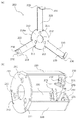
図1(a)は出力軸160側に視点をおいた遊星歯車機構1の斜視図、(b)は駆動源側に視点をおいた斜視図、図2(a)は遊星歯車機構1の一例を示す縦断面模式図、(b)は横断面斜視図、図3は出力軸160側に視点をおいた遊星歯車ユニット100の斜視図、図4(a)は固定部材200の展開斜視図、(b)は遊星歯車ユニット100を固定する状態の固定部材200を示す斜視図である。以下、図面を参照しながら、遊星歯車機構1の全体構成及び動作を説明する。
(1) Overall configuration and operation of planetary gear mechanism Fig. 1(a) is a perspective view of the planetary gear mechanism 1 with a viewpoint on the
(1.1)遊星歯車機構の全体構成
各図には、複数の遊星歯車ユニット100を重ね合せて3段構成とした遊星歯車機構1の例が示されているが、本実施形態に係る遊星歯車機構1は必要とされる減速比に応じて複数の遊星歯車ユニット100を重ね合わせて構成することができる。
遊星歯車機構1は、図1に示すように、中心軸線方向に重ね合わされた複数の遊星歯車ユニット100が固定部材200で挟み込まれた状態で固定された駆動伝達装置である。
(1.1) Overall Configuration of Planetary Gear Mechanism Although each drawing shows an example of the planetary gear mechanism 1 having a three-stage configuration in which a plurality of
As shown in FIG. 1, the planetary gear mechanism 1 is a drive transmission device in which a plurality of
(1.2)遊星歯車機構
図2に示すように、遊星歯車機構1は、太陽歯車120、内歯歯車130、遊星歯車140、キャリア150からなる複数の遊星歯車ユニット100と、重ね合わされた遊星歯車ユニット100を入力側(駆動源側)及び出力側(被取り付け体側)で保持する第1カバー体170、第2カバー体180と、重ね合わされた遊星歯車ユニット100を第1カバー体170及び第2カバー体180を介して中心軸方向に沿って挟み込んで固定する固定部材200と、最終段の遊星歯車ユニット100のキャリア150に固定された出力軸160、から構成されている。
(1.2) Planetary Gear Mechanism As shown in FIG. 2, the planetary gear mechanism 1 includes a plurality of
太陽歯車120は、遊星歯車ユニット100の中心軸線上で駆動源としてのモータM(図6参照)に接続され、モータMの駆動力をキャリア150に回転支持された複数の遊星歯車140に伝達する。
The
遊星歯車140は、図2(b)に示すように、キャリア150の周方向の3箇所に等間隔に支持軸141で回転自在に支持され、これらと噛み合う太陽歯車120から回転駆動を受けて自転するとともに、内歯歯車130の内面に形成された内歯133に噛み合って中心軸線上でキャリア150とともに公転する。
As shown in FIG. 2B, the
内歯歯車130は、全体が中空部を有する円筒状の筒体131と、筒体131の内面132の中央部に形成された内歯133からなる。内歯133が形成された内面132の両側は円筒形状で、一端側にはキャリア150の円板部151の周縁部151aが当接して、キャリア150を外側から回転支持している。
The
図3に示すように、内歯歯車130の筒体131は、互いに嵌まり合う凹形状131aと凸形状131bからなる相補形状を有し重ね合わされたそれぞれの内歯歯車130同士の回転方向に位置決めされる。また、回転方向に位置決めされた状態で中心軸線方向に延びる凹形状としての係合凹部135(図3参照)が形成されている。
As shown in FIG. 3, the
図3に示すように、最終段となる重ね合わされた遊星歯車ユニット100の出力軸160側を保持する第2カバー体180には、後述する固定部材200の脚部230が位置決めされる位置決め穴181と、固定部材200の脚部230に形成された係合凸部233と嵌まり合う係合溝182が形成されている。
As shown in FIG. 3, in the
出力軸160は、最終段の遊星歯車ユニット100のキャリア150に固定されるとともに、第2カバー体180で回転支持され、遊星歯車ユニット100で減速された回転駆動力を被駆動体に伝達する。
The
図4に示すように、固定部材200は、円板部210と、帯部材220と、脚部230からなる板状部材であり、円板部210には、駆動源としてのモータM(図6参照)が取り付けられる取り付け部としての取り付け孔211と、モータMのインロー部Ma(図6(a) 参照)に嵌合して位置決めされる位置決め孔212が形成されている。
As shown in FIG. 4, the fixing
帯部材220は、円板部210の外縁210aを基端として周方向に等間隔に遊星歯車ユニット100の中心軸線方向に延びるように形成され、内歯歯車130の筒体131に形成された係合凹部135に嵌まり合うことで重ね合わされた遊星歯車ユニット100を回転不能に固定する。
The
脚部230は、円板部210と相対するように他端側で帯部材220の端部を中心軸線方向と交差(直交)する方向に折り曲げて形成され、中心軸線方向に向かって突出する位置決め突起231と、中心軸線方向に突出する係合凸部233を有する。
位置決め突起231は、被取り付け体と締結する締結部としての締結孔232と同軸にバーリング加工された円筒体であり、第2カバー体180に形成された位置決め穴181に嵌まり合うことで脚部230が第2カバー体180に位置決めされる。係合凸部233は、第2カバー体180に形成された係合溝182に係合して脚部230が強固に固定される。
The
The
固定部材200は、複数の遊星歯車ユニット100の駆動源側と出力軸160側を第1カバー体170及び第2カバー体180で保持した状態で、帯部材220で連結された円板部210と脚部230で挟み込んで固定している。
The fixing
遊星歯車機構1のそれぞれの太陽歯車120、内歯歯車130、遊星歯車140、キャリア150は合成樹脂材料を用いた成形品で構成される。合成樹脂材料としては、POM(ポリアセタール)、PA(ポリアミド)、PC(ポリカーボネイト)、PET(ポリエチレンテレフタレート)、PPS(ポリフェニレンサルファイド)、LCP(液晶ポリマー)又はこれらの合成樹脂にガラス繊維又は炭素繊維を添加した強化合成樹脂が挙げられる。
固定部材200は、金属性の薄板部材を金型で打ち抜いて形成される。
Each of the
The fixing
(1.3)動作
固定部材200の円板部210に取り付けられたモータMの駆動で太陽歯車120が回転駆動されると、3つの遊星歯車140の各々が、自身の支持軸141を回転中心として自転する。また、3つの遊星歯車140の各々は、内歯歯車130の内歯133と噛み合っているために、中心軸線を中心として公転する。
そして、3つの遊星歯車140の公転が開始されると、遊星歯車140を支持するキャリア150は、内歯歯車130の内面132に当接支持されて太陽歯車120の回転に対し減速回転を開始する。
(1.3) Operation When the
When the revolution of the three
遊星歯車ユニット100が、図2に示すように複数段重ね合わせて構成されている場合(図2の例では3段)には、キャリア150の外面に設けられ減速回転する太陽歯車120Aが2段目の遊星歯車ユニット100の入力となる。
そして、2段目の遊星歯車ユニット100では、2段目の内歯歯車130と2段目の太陽歯車120Aとに噛み合う2段目の遊星歯車140が、2段目のキャリア150により支持されて、自転しながら2段目の太陽歯車120Aの外周を公転する。そして、公転する遊星歯車140を支持する2段目のキャリア150が減速回転する。
When the
In the second-stage
減速回転する2段目のキャリア150の外面には太陽歯車120Aが設けられており、3段目の内歯歯車130と3段目の太陽歯車120Aとに噛み合う3段目の遊星歯車140が、3段目のキャリア150により支持されて、自転しながら3段目の太陽歯車120Aの外周を公転する。公転する遊星歯車140を支持する3段目のキャリア150の外面には出力軸160が固定され、出力軸160には3段に減速された回転が伝達され、被駆動体を回転駆動する。
The
(2)遊星歯車ユニットの固定構造
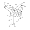
図5は遊星歯車機構1における遊星歯車ユニット100の固定を説明する斜視図、図6(a)は駆動源の斜視図、(b)は駆動源が取り付けられた遊星歯車機構1の斜視図である。
それぞれの遊星歯車ユニット100同士は、それぞれの内歯歯車130の筒体131に形成された凹形状131aと凸形状131bが嵌まり合って回転方向に対して位置決めされた状態で、第1カバー体170及と第2カバー体180で保持される。
(2) Fixing Structure of Planetary Gear Unit FIG. 5 is a perspective view illustrating fixing of the
In each
固定部材200は、図5に示すように、円板部210が駆動源側の第1カバー体170に取り付けられ、円板部210の外縁210aに等間隔に連結された帯部材220を第2カバー体180に向かって折り曲げる(図5中 矢印参照)と、固定部材200の帯部材220が内歯歯車130の外周面130a上に形成された係合凹部135に嵌まり込む。
As shown in FIG. 5, in the fixing
帯部材220が内歯歯車130の係合凹部135に嵌まり込んだ状態で、固定部材200の脚部230は、位置決め突起231が第2カバー体180の位置決め穴181に嵌まり合って第2カバー体180に位置決めされると同時に、係合凸部233が、第2カバー体180に形成された係合溝182に係合して脚部230が強固に固定される。
With the
本実施形態に係る遊星歯車機構1は、帯部材220が内歯歯車130の係合凹部135に嵌まり込んで遊星歯車ユニット100の内歯歯車130から径方向に突出することなく重ね合わされた遊星歯車ユニット100を固定して、遊星歯車機構1を小型化することができる。
In the planetary gear mechanism 1 according to the present embodiment, the
また、遊星歯車機構1の駆動源M側を固定する固定部材200の円板部210は、位置決め孔212が駆動源としてのモータMのインロー部Ma(図6(a) 参照)に嵌合して位置決めされ、取り付け孔211にモータMが直接取り付けられるために、遊星歯車機構1を小型化するとともにモータMを金属製の固定部材200に導通接地することができる。
Further, in the
遊星歯車機構1の出力軸160側を固定する固定部材200の脚部230は、位置決め突起231と同軸に形成された締結孔232を介して被取り付け体に締結される。そのために、遊星歯車機構1を小型化するともに、遊星歯車機構1の被取り付け体への締結と固定部材200による遊星歯車ユニット100の固定を共通の締結部材で行い低コスト化することができる。
The
1・・・遊星歯車機構
100・・・遊星歯車ユニット
120、120A・・・太陽歯車
130・・・内歯歯車
130a・・・外周面
133・・・内歯
135・・・係合凹部(内歯歯車)
140・・・遊星歯車
150・・・キャリア
160・・・出力軸
170・・・第1カバー体
180・・・第2カバー体
200・・・固定部材
210・・・円板部
211・・・取り付け孔
212・・・位置決め孔
220・・・帯部材
230・・・脚部
231・・・位置決め突起
232・・・締結孔
233・・・係合凸部
M・・・モータ
1...
140...
M: Motor
Claims (6)
一端に前記駆動源を取り付ける取り付け部と他端に被取り付け体と締結する締結部を有し、前記内歯歯車の回転を禁止して前記遊星歯車ユニットを中心軸線方向に重ね合わせて固定する固定部材と、を備えた、
ことを特徴とする遊星歯車機構。 A plurality of planetary gear units including a sun gear that receives rotational driving force from a drive source, an internal gear, a planetary gear, and a carrier;
A fixing having a mounting portion for mounting the drive source at one end and a coupling portion for coupling with a body to be mounted at the other end, and prohibiting rotation of the internal gear to superimpose and fix the planetary gear unit in the central axis direction. And a member,
A planetary gear mechanism characterized in that.
ことを特徴とする請求項1に記載の遊星歯車機構。 The fixing member includes a disc portion provided with the mounting portion, a plurality of strip members whose base ends are connected at equal intervals in the circumferential direction of the disc portion and extend in the central axis direction, and the other strip members. And a leg portion that extends in a direction intersecting the central axis direction at the end relative to the disc portion.
The planetary gear mechanism according to claim 1, wherein:
ことを特徴とする請求項2に記載の遊星歯車機構。 The disc portion has a positioning hole that is fitted and positioned in the spigot portion of the drive source,
The planetary gear mechanism according to claim 2, wherein.
ことを特徴とする請求項2に記載の遊星歯車機構。 The leg portion has an engaging protrusion protruding in the central axis direction and fitted into an engaging groove provided in the planetary gear unit,
The planetary gear mechanism according to claim 2, wherein.
ことを特徴とする請求項2又は3に記載の遊星歯車機構。 The leg portion has a positioning protrusion that protrudes in the central axis direction, and is positioned in an engagement hole provided in the planetary gear unit,
The planetary gear mechanism according to claim 2 or 3, characterized in that.
ことを特徴とする請求項2ないし5のいずれか1項に記載の遊星歯車機構。 The band member is fitted in a concave shape formed on the outer peripheral surface of the internal gear to inhibit rotation of the internal gear,
The planetary gear mechanism according to any one of claims 2 to 5, characterized in that:
Priority Applications (1)
| Application Number | Priority Date | Filing Date | Title |
|---|---|---|---|
| JP2016126590A JP6729063B2 (en) | 2016-06-27 | 2016-06-27 | Planetary gear mechanism |
Applications Claiming Priority (1)
| Application Number | Priority Date | Filing Date | Title |
|---|---|---|---|
| JP2016126590A JP6729063B2 (en) | 2016-06-27 | 2016-06-27 | Planetary gear mechanism |
Publications (2)
| Publication Number | Publication Date |
|---|---|
| JP2018003858A JP2018003858A (en) | 2018-01-11 |
| JP6729063B2 true JP6729063B2 (en) | 2020-07-22 |
Family
ID=60944905
Family Applications (1)
| Application Number | Title | Priority Date | Filing Date |
|---|---|---|---|
| JP2016126590A Active JP6729063B2 (en) | 2016-06-27 | 2016-06-27 | Planetary gear mechanism |
Country Status (1)
| Country | Link |
|---|---|
| JP (1) | JP6729063B2 (en) |
Family Cites Families (5)
| Publication number | Priority date | Publication date | Assignee | Title |
|---|---|---|---|---|
| JP2004011845A (en) * | 2002-06-10 | 2004-01-15 | Matsushita Electric Ind Co Ltd | Planetary gear reduction gear and battery driver using it |
| DE102009052898B4 (en) * | 2009-11-13 | 2011-12-29 | Saia-Burgess Dresden Gmbh | Multi-stage planetary gearbox |
| US8323143B2 (en) * | 2009-12-02 | 2012-12-04 | Fairfield Manufacturing Company, Inc. | Integrated spindle-carrier electric wheel drive |
| JP5480845B2 (en) * | 2011-05-27 | 2014-04-23 | シナノケンシ株式会社 | Planetary gear mechanism |
| JP2015183830A (en) * | 2014-03-26 | 2015-10-22 | Ntn株式会社 | in-wheel motor drive device |
-
2016
- 2016-06-27 JP JP2016126590A patent/JP6729063B2/en active Active
Also Published As
| Publication number | Publication date |
|---|---|
| JP2018003858A (en) | 2018-01-11 |
Similar Documents
| Publication | Publication Date | Title |
|---|---|---|
| US9815192B1 (en) | Servo and robot with servo | |
| US8100807B2 (en) | Reduction gear transmission and solar tracking photovoltaic power generation unit utilizing the same | |
| CN102042389B (en) | Vehicle power transmission device | |
| US9989141B2 (en) | Fastening structure for fastening driven member to strain wave gearing device unit, and strain wave gearing device unit | |
| KR101449392B1 (en) | Reducer | |
| TW201520443A (en) | Bearing holder, bearing mechanism, and strain wave gearing device | |
| US10683912B2 (en) | Planetary gear mechanism | |
| WO2014133118A1 (en) | Motor device | |
| JP2014055653A (en) | Planetary gear speed reduction mechanism | |
| CN107850188B (en) | Planetary roller driving type internal connection type planetary gear speed reducer | |
| WO2012036033A1 (en) | Planetary gear device | |
| JP2015110382A (en) | Wheel drive device | |
| JP5480845B2 (en) | Planetary gear mechanism | |
| JP6228588B2 (en) | Deceleration device and geared motor, electronic device and robot provided with the same | |
| JP6729063B2 (en) | Planetary gear mechanism | |
| WO2018194112A1 (en) | Wave gear speed reduction unit and power unit equipped with same | |
| WO1999020917A1 (en) | Silk hat flexible engagement gear device | |
| JP2014081001A (en) | Speed reducer | |
| JP6598215B2 (en) | Cam apparatus and method of manufacturing cam apparatus | |
| KR20130021325A (en) | Geared motor and method for manufacturing thereof | |
| JP5520494B2 (en) | Differential device | |
| JP6148443B2 (en) | Reduction mechanism and motor with reduction gear | |
| KR102185296B1 (en) | Wave gear device and wave generator | |
| CN213270922U (en) | Gear device and geared motor | |
| WO2022208659A1 (en) | Planetary gear device and actuator |
Legal Events
| Date | Code | Title | Description |
|---|---|---|---|
| A621 | Written request for application examination |
Free format text: JAPANESE INTERMEDIATE CODE: A621 Effective date: 20190423 |
|
| A977 | Report on retrieval |
Free format text: JAPANESE INTERMEDIATE CODE: A971007 Effective date: 20200213 |
|
| A131 | Notification of reasons for refusal |
Free format text: JAPANESE INTERMEDIATE CODE: A131 Effective date: 20200218 |
|
| A521 | Written amendment |
Free format text: JAPANESE INTERMEDIATE CODE: A523 Effective date: 20200408 |
|
| TRDD | Decision of grant or rejection written | ||
| A01 | Written decision to grant a patent or to grant a registration (utility model) |
Free format text: JAPANESE INTERMEDIATE CODE: A01 Effective date: 20200602 |
|
| A61 | First payment of annual fees (during grant procedure) |
Free format text: JAPANESE INTERMEDIATE CODE: A61 Effective date: 20200615 |
|
| R150 | Certificate of patent or registration of utility model |
Ref document number: 6729063 Country of ref document: JP Free format text: JAPANESE INTERMEDIATE CODE: R150 |
|
| S533 | Written request for registration of change of name |
Free format text: JAPANESE INTERMEDIATE CODE: R313533 |
|
| R350 | Written notification of registration of transfer |
Free format text: JAPANESE INTERMEDIATE CODE: R350 |