JP6727770B2 - Toner and toner manufacturing method - Google Patents
Toner and toner manufacturing method Download PDFInfo
- Publication number
- JP6727770B2 JP6727770B2 JP2015156581A JP2015156581A JP6727770B2 JP 6727770 B2 JP6727770 B2 JP 6727770B2 JP 2015156581 A JP2015156581 A JP 2015156581A JP 2015156581 A JP2015156581 A JP 2015156581A JP 6727770 B2 JP6727770 B2 JP 6727770B2
- Authority
- JP
- Japan
- Prior art keywords
- toner
- organic
- fine particles
- inorganic composite
- composite fine
- Prior art date
- Legal status (The legal status is an assumption and is not a legal conclusion. Google has not performed a legal analysis and makes no representation as to the accuracy of the status listed.)
- Active
Links
Images
Classifications
-
- G—PHYSICS
- G03—PHOTOGRAPHY; CINEMATOGRAPHY; ANALOGOUS TECHNIQUES USING WAVES OTHER THAN OPTICAL WAVES; ELECTROGRAPHY; HOLOGRAPHY
- G03G—ELECTROGRAPHY; ELECTROPHOTOGRAPHY; MAGNETOGRAPHY
- G03G9/00—Developers
- G03G9/08—Developers with toner particles
- G03G9/0825—Developers with toner particles characterised by their structure; characterised by non-homogenuous distribution of components
-
- G—PHYSICS
- G03—PHOTOGRAPHY; CINEMATOGRAPHY; ANALOGOUS TECHNIQUES USING WAVES OTHER THAN OPTICAL WAVES; ELECTROGRAPHY; HOLOGRAPHY
- G03G—ELECTROGRAPHY; ELECTROPHOTOGRAPHY; MAGNETOGRAPHY
- G03G9/00—Developers
- G03G9/08—Developers with toner particles
- G03G9/0802—Preparation methods
- G03G9/0808—Preparation methods by dry mixing the toner components in solid or softened state
-
- G—PHYSICS
- G03—PHOTOGRAPHY; CINEMATOGRAPHY; ANALOGOUS TECHNIQUES USING WAVES OTHER THAN OPTICAL WAVES; ELECTROGRAPHY; HOLOGRAPHY
- G03G—ELECTROGRAPHY; ELECTROPHOTOGRAPHY; MAGNETOGRAPHY
- G03G9/00—Developers
- G03G9/08—Developers with toner particles
- G03G9/0827—Developers with toner particles characterised by their shape, e.g. degree of sphericity
-
- G—PHYSICS
- G03—PHOTOGRAPHY; CINEMATOGRAPHY; ANALOGOUS TECHNIQUES USING WAVES OTHER THAN OPTICAL WAVES; ELECTROGRAPHY; HOLOGRAPHY
- G03G—ELECTROGRAPHY; ELECTROPHOTOGRAPHY; MAGNETOGRAPHY
- G03G9/00—Developers
- G03G9/08—Developers with toner particles
- G03G9/097—Plasticisers; Charge controlling agents
- G03G9/09708—Inorganic compounds
- G03G9/09716—Inorganic compounds treated with organic compounds
-
- G—PHYSICS
- G03—PHOTOGRAPHY; CINEMATOGRAPHY; ANALOGOUS TECHNIQUES USING WAVES OTHER THAN OPTICAL WAVES; ELECTROGRAPHY; HOLOGRAPHY
- G03G—ELECTROGRAPHY; ELECTROPHOTOGRAPHY; MAGNETOGRAPHY
- G03G9/00—Developers
- G03G9/08—Developers with toner particles
- G03G9/097—Plasticisers; Charge controlling agents
- G03G9/09733—Organic compounds
Landscapes
- Physics & Mathematics (AREA)
- General Physics & Mathematics (AREA)
- Chemical & Material Sciences (AREA)
- Inorganic Chemistry (AREA)
- Developing Agents For Electrophotography (AREA)
Description
本発明は、電子写真法、静電記録法、磁気記録法などに用いられるトナー及びトナーの製造方法に関する。 The present invention relates to a toner used in electrophotography, an electrostatic recording method, a magnetic recording method, and the like, and a method for manufacturing the toner.
近年、コスト意識や環境意識の高まりから、コピー機やプリンター等の電子写真装置は従来以上に、長期間使用できること求められている。そして、長期間の使用を可能とするための手法の一例として、トナー容器により多くのトナーを充填することが行われている。これによりユーザーの利便性を向上させると同時にコスト的にも、また省資源の観点からもユーザーにメリットを与えることができる。 In recent years, due to increasing cost consciousness and environmental consciousness, electrophotographic apparatuses such as copying machines and printers are required to be usable for a longer period of time than ever before. Then, as an example of a method for enabling long-term use, a toner container is filled with a large amount of toner. As a result, the convenience of the user can be improved, and at the same time, the user can benefit from the viewpoint of cost and resource saving.
しかし、トナーの充填量を増やすためには、技術的に解決すべき課題が多々存在する。 However, there are many technical problems to be solved in order to increase the filling amount of the toner.
容器内部のトナーは、現像装置にトナーを供給するための撹拌を継続的に受けることになるため、物理的な負荷を長期間にわたり受けることとなる。また、トナーの総量が増加する場合、トナー容器内部の撹拌・循環機構も従来よりも大型化・強化せざるを得ず、この点でもトナーへの物理的な負荷は増大する。 The toner inside the container is continuously subjected to agitation for supplying the toner to the developing device, and thus is subjected to a physical load for a long period of time. In addition, when the total amount of toner increases, the stirring/circulating mechanism inside the toner container has to be made larger and stronger than in the past, and in this respect also, the physical load on the toner increases.
トナーへの流動性の付与は、外添剤の添加によって行われている。しかしながら、トナーが物理的負荷を受けた場合には、外添剤がトナー表面に埋没してしまい、トナーの流動性が低下してしまうという課題があった。この傾向は、特に小粒径の外添剤を用いた場合において顕著であった。 The fluidity is imparted to the toner by adding an external additive. However, when the toner is subjected to a physical load, there is a problem that the external additive is buried in the toner surface and the fluidity of the toner is lowered. This tendency was remarkable especially when an external additive having a small particle size was used.
そこで、より埋没し難い大径の無機粒子や有機無機複合微粒子を外添剤として使用することで、トナーの物理的負荷に対する耐久性を向上させる試みが多く行われている(特許文献1乃至3)。しかし、これら大径外添剤は、その大きさ故にトナー表面に対する物理的・静電的な付着力が弱いため遊離し易く、電子写真プロセス中で様々な部材汚染を引き起こすという課題がある。 Therefore, many attempts have been made to improve the durability of the toner against a physical load by using large-diameter inorganic particles or organic-inorganic composite fine particles that are less likely to be buried as external additives (Patent Documents 1 to 3). ). However, these large-diameter external additives are weak in physical and electrostatic adhesion to the toner surface due to their size, and are therefore easily liberated, which poses a problem of causing various member contamination during the electrophotographic process.
そのためこれら大径外添剤を使用する場合、従来の小径外添剤をトナー母粒子に外添する条件よりも更に強くトナー表面に付着させる必要があり、そのための外添条件の検討が幅広く行われている。より強くトナー表面に付着させるために、処理時間を長くする検討もなされている(特許文献4)。しかしながら、この場合には、大径外添剤がトナーの凹部に掃き寄せられてしまい、外添剤による被覆効果を十分に得るには至っていない。 Therefore, when using these large-diameter external additives, it is necessary to adhere them to the toner surface more strongly than the conventional conditions for externally adding the small-diameter external additives to the toner base particles. It is being appreciated. In order to make the toner adhere to the surface of the toner more strongly, it has been studied to extend the processing time (Patent Document 4). However, in this case, the large-diameter external additive is swept up into the concave portions of the toner, and the effect of coating with the external additive has not been sufficiently obtained.
本発明の目的は上記課題を解決できるトナーを提供することにある。 An object of the present invention is to provide a toner that can solve the above problems.
具体的には、トナー容器内に多量に充填され、長期使用に供された場合であっても、部材汚染の発生が抑制されており、安定した画像濃度を有する画像を得ることができるトナーを提供することである。 Specifically, even when a large amount is filled in a toner container and used for a long period of time, the occurrence of member contamination is suppressed, and a toner capable of obtaining an image having a stable image density is obtained. Is to provide.
さらに、本発明は、上記のトナーを製造することができる製造方法を提供することを目的とする。 Further, the present invention aims to provide a manufacturing method capable of manufacturing the above toner.
本発明は、結着樹脂、着色剤及び離型剤を含有するトナー粒子と、
有機無機複合微粒子と、
無機微粒子aと
を有するトナーであって、
該有機無機複合微粒子は、
(1)樹脂粒子と無機微粒子bとを有し、該樹脂粒子の表面に該無機微粒子bに由来する凸部が存在する構造を有する粒子であり、
(2)個数平均粒径(D1)が50nm以上500nm以下であり、
(3)倍率20万倍に拡大して測定される形状係数SF−2が103以上120以下であり、
(4)該トナー粒子に対して固着している該有機無機複合微粒子の割合Y(質量部)が、該トナー粒子100質量部に対して0.45質量部以上3.00質量部以下であり、該トナー粒子に対して固着している該有機無機複合微粒子の割合Yは、以下の測定方法で求められるものであり、
該トナー粒子100質量部に対する該有機無機複合微粒子の割合をX質量部としたとき、該Xと該Yとが、
X−Y≦0.30
を満たし、
下式で算出される、トナー粒子表面における該有機無機複合微粒子の単位拡散指数が0.75以上であり、該単位拡散指数は、以下の測定方法で求められるものであり、
該無機微粒子aは、BET比表面積が50m2/g以上400m2/g以下である、
ことを特徴とするトナーに関する。
・トナー粒子に対して固着している有機無機複合微粒子の量Y(質量部)の測定方法
非イオン界面活性剤、陰イオン界面活性剤及び有機ビルダーからなるpH7の中性洗剤の10質量%水溶液を数滴加えたイオン交換水にトナーをウルトラソニッククリーナーを用いて超音波分散し、24時間静置する。この上澄み液を採取して乾燥し、外添剤を単離する。トナーには複数の外添剤が外添されているため、25℃及び5000rpmで1分間の条件で上澄み液を遠心分離し、有機無機複合微粒子を単離する。
単離した有機無機複合微粒子を、再度上記10質量%水溶液を数滴加えたイオン交換水に基準量分散し、有機無機複合微粒子の濃度が既知の標準溶液を作製する。
次に、上記10質量%水溶液を数滴加えたイオン交換水にトナーを分散し、トナーの濃度が既知の第一のトナー分散液を作製した後、ウルトラソニッククリーナーを用いて超音波で10秒分散し、その後、遠心分離によりトナー粒子を沈降させる。再度ウルトラソニッククリーナーを用いて超音波で20秒分散した後、遠心分離によりトナー粒子を沈降させる。再度ウルトラソニッククリーナーを用いて超音波で60秒分散し、トナー粒子に対して固着していない弱付着の有機無機複合微粒子をトナー粒子から離した後、遠心分離によりトナー粒子を沈降させる。この段階での第一の上澄み液及び標準溶液に対してそれぞれディスク遠心式粒度分布測定装置による測定を行い、両液の有機無機複合微粒子の粒径の位置に現れるピークの面積を比較し、第一の上澄み液における弱付着の有機無機複合微粒子の濃度を求める。第一の上澄み液における弱付着の有機無機複合微粒子の濃度から、第一のトナー分散液における弱付着の有機無機複合微粒子の濃度を求める。第一のトナー分散液における弱付着の有機無機複合微粒子及び第一のトナー分散液におけるトナーの濃度から、トナーに含まれる弱付着の有機無機複合微粒子の量(トナー100質量部に対する量(質量部))を求める。
また、上記10質量%水溶液を数滴加えたイオン交換水10.0gにトナー1.0gを分散し、トナーの濃度が既知の第二のトナー分散液を作製した後、超音波ホモジナイザーを用いて超音波処理を3時間行い、全部の有機無機複合微粒子(トナー粒子に対して固着している有機無機複合微粒子及び固着していない弱付着の有機無機複合微粒子)をトナー粒子から離した後、遠心分離によりトナー粒子を沈降させる。この段階で第二の上澄み液及び標準溶液に対してそれぞれディスク遠心式粒度分布測定による測定を行い、両液の有機無機複合微粒子の粒径の位置に現れるピークの面積を比較し、第二の上澄み液における有機無機複合微粒子の濃度を求める。第二のトナー分散液における有機無機複合微粒子及び第二のトナー分散液におけるトナーの濃度から、トナーに含まれる有機無機複合微粒子の全量(トナー100質量部に対する量(質量部):全添加部数)を求める。
トナーに含まれる有機無機複合微粒子の全量(質量部)からトナーに含まれる弱付着の有機無機複合微粒子の量(質量部)を引いた値を、トナーに含まれるトナー粒子に対して固着している有機無機複合微粒子の量Y(質量部)とする。
・単位拡散指数の測定方法
単位拡散指数は、単位拡散指数=Sr/Siで算出する。Srは、実測から求められる有機無機複合微粒子によるトナー粒子表面の被覆率であり、Siは、有機無機複合微粒子が理想的に拡散した場合の有機無機複合微粒子によるトナー粒子表面の被覆率である。
Srは、走査型電子顕微鏡にて撮影されたトナー表面画像を、画像解析ソフトにより、次の通り解析して算出する。まず、上記トナー表面画像を2値化処理し、上記トナー表面画像を正方形で12分割してそれぞれ解析する。このとき、領域の面積(C)は24000〜26000ピクセルになるようにする。ここで有機無機複合微粒子の輪郭の領域指定を行い、有機無機複合微粒子の被覆面積(D)を算出する。正方形の領域の面積C、有機無機複合微粒子の被覆面積Dから、Sr(%)=D/C×100で被覆率Srが求められる。有機無機複合微粒子の被覆率の計算はトナー30粒子以上について行う。得られた全データの平均値を本発明におけるSrとする。
Siは、次の通り算出する。まず、有機無機複合微粒子のトナー1gあたりの含有質量(Ay)[g]と密度(Gy)[g/m3]、粒径(Dy)[m]から有機無機複合微粒子のトナー1gあたりの含有個数(N)を計算する。Ayはディスク遠心式粒度分布測定装置で測定する。Gyは乾式自動密度計で測定する。Dyは走査型電子顕微鏡で測定する。Nは、N=Ay/(4/3・π・(Dy/2)3・Gy)で算出する。次に、Sr測定時と同様に撮影した走査型電子顕微鏡の画像のうち、凝集せず単分散している有機無機複合微粒子を30個以上選択し、そのうち面積が小さい方から10個の平均値を求め、算出した平均値を有機無機複合微粒子の1個当たりの被覆面積(S1)[m2]とする。また、外添剤を全て遊離させたトナー粒子の1gあたりの表面積(Sm)[m2]を定容法によるガス吸着法を測定方式として採用している自動比表面積・細孔分布測定装置を用いて計測する。Siは、Si(%)=N×S1/Sm×100で算出する。
The present invention is a toner particle containing a binder resin, a colorant and a release agent,
Organic-inorganic composite fine particles,
A toner having inorganic fine particles a,
The organic-inorganic composite fine particles,
(1) A particle having resin particles and inorganic fine particles b, and having a structure in which convex portions derived from the inorganic fine particles b are present on the surface of the resin particles,
(2) The number average particle diameter (D1) is 50 nm or more and 500 nm or less,
(3) The shape factor SF-2 measured at a magnification of 200,000 times is 103 or more and 120 or less,
(4) The ratio Y (parts by mass) of the organic-inorganic composite fine particles fixed to the toner particles is 0.45 parts by mass or more and 3.00 parts by mass or less with respect to 100 parts by mass of the toner particles. The ratio Y of the organic-inorganic composite fine particles fixed to the toner particles is obtained by the following measuring method,
When the ratio of the organic-inorganic composite fine particles to 100 parts by mass of the toner particles is X parts by mass, the X and the Y are
XY≦0.30
The filling,
The unit diffusion index of the organic-inorganic composite fine particles on the surface of the toner particles calculated by the following formula is 0.75 or more, and the unit diffusion index is obtained by the following measuring method,
The BET specific surface area of the inorganic fine particles a is 50 m 2 /g or more and 400 m 2 /g or less,
The present invention relates to a toner.
Method for measuring the amount Y (parts by mass) of the organic-inorganic composite fine particles adhered to the
The isolated organic-inorganic composite fine particles are dispersed again in a standard amount in ion-exchanged water to which a few drops of the above 10 mass% aqueous solution are added to prepare a standard solution having a known concentration of the organic-inorganic composite fine particles .
Next, the toner is dispersed in ion-exchanged water to which a few drops of the 10% by mass aqueous solution are added to prepare a first toner dispersion liquid having a known toner concentration , and then ultrasonic waves are applied for 10 seconds using an ultrasonic cleaner. Disperse and then sediment the toner particles by centrifugation. The toner particles are again dispersed by ultrasonic waves for 20 seconds using an Ultrasonic cleaner, and then the toner particles are settled by centrifugation. The particles are again dispersed by ultrasonic waves for 60 seconds using an Ultrasonic cleaner to separate the weakly adhering organic-inorganic composite fine particles not fixed to the toner particles from the toner particles, and then the toner particles are settled by centrifugation. At this stage, the first supernatant and the standard solution were respectively measured by a disk centrifugal type particle size distribution measuring device, and the areas of the peaks appearing at the particle size positions of the organic-inorganic composite fine particles of both solutions were compared . The concentration of weakly adhering organic-inorganic composite fine particles in one supernatant is obtained. From the concentration of the weakly adhered organic-inorganic composite fine particles in the first supernatant liquid, the concentration of the weakly adhered organic-inorganic composite fine particles in the first toner dispersion liquid is determined. From the concentration of the weakly adhering organic-inorganic composite fine particles in the first toner dispersion and the concentration of the toner in the first toner dispersion, the amount of the weakly adhering organic-inorganic composite fine particles contained in the toner (amount per 100 parts by mass of toner (parts by mass) )) Ru determined.
Further , 1.0 g of the toner is dispersed in 10.0 g of ion-exchanged water to which a few drops of the 10 mass% aqueous solution are added to prepare a second toner dispersion liquid having a known toner concentration , and then an ultrasonic homogenizer is used. Ultrasonic wave treatment for 3 hours to separate all the organic-inorganic composite fine particles (organic-inorganic composite fine particles fixed to the toner particles and weakly adhered organic-inorganic composite fine particles not fixed to the toner particles) from the toner particles , The toner particles are settled by centrifugation. Each was measured that by the disc centrifuge particle size distribution measured at this stage for the second supernatant and the standard solution, comparing the area of the peak appearing at the position of the particle size of the organic-inorganic composite particles of the two solutions, the The concentration of organic-inorganic composite fine particles in the second supernatant is obtained. From the concentration of the organic-inorganic composite fine particles in the second toner dispersion liquid and the toner concentration in the second toner dispersion liquid, the total amount of the organic-inorganic composite fine particles contained in the toner (amount per 100 parts by mass of toner (parts by mass): total number of addition parts ) the Ru asked.
Fixing all amounts minus the amount of the organic-inorganic composite fine particles of weak adhesion (parts by mass) contained from (parts by weight) in the toner of the organic-inorganic composite particles contained in the toner, the toner particles contained in the toner and the amount of the organic-inorganic composite fine particles Y (parts by weight) are.
-Measurement method of unit diffusion index The unit diffusion index is calculated by unit diffusion index=Sr/Si. Sr is the coverage of the toner particle surface with the organic-inorganic composite fine particles, which is obtained from actual measurement, and Si is the coverage of the toner particle surface with the organic-inorganic composite fine particles when the organic-inorganic composite fine particles are ideally diffused.
Sr is calculated by analyzing the toner surface image photographed by the scanning electron microscope with the image analysis software as follows. First, the toner surface image is binarized, and the toner surface image is divided into 12 squares and analyzed. At this time, the area (C) of the area is set to 24000 to 26000 pixels. Here, the contour area of the organic-inorganic composite fine particles is designated, and the covered area (D) of the organic-inorganic composite fine particles is calculated. From the area C of the square region and the coating area D of the organic-inorganic composite fine particles, the coverage Sr is calculated by Sr(%)=D/C×100. The calculation of the coverage of the organic-inorganic composite fine particles is performed for 30 or more toner particles. The average value of all the obtained data is Sr in the present invention.
Si is calculated as follows. First, from the content (Ay) [g] and the density (Gy) [g/m 3 ] and the particle size (Dy) [m] of the organic-inorganic composite fine particles per 1 g of the toner, the content of the organic-inorganic composite fine particles per 1 g of the toner is described. Calculate the number (N). Ay is measured by a disc centrifugal type particle size distribution measuring device. Gy is measured by a dry type automatic densimeter. Dy is measured with a scanning electron microscope. N is calculated by N=Ay/(4/ 3 ·π·(Dy/2) 3 ·Gy). Next, from the images of the scanning electron microscope taken in the same manner as in the Sr measurement, 30 or more organic-inorganic composite fine particles that were not aggregated and were monodispersed were selected, and the average value of 10 from the smaller area was selected. And the calculated average value is defined as the coating area (S1) [m 2 ] per organic-inorganic composite fine particle. In addition, an automatic specific surface area/pore distribution measuring device adopting a gas adsorption method based on a constant volume method as a measuring method for the surface area (Sm) [m 2 ] per 1 g of toner particles in which all the external additives are released. Use to measure. Si is calculated by Si(%)=N×S1/Sm×100.
また、本発明は、上記構成のトナーの製造方法であって、
(1)処理室内に回転体を具備する処理装置を用いて該トナー粒子と該有機無機複合微粒子とを混合し、混合物を得る第一混合工程と、
(2)処理室内に回転体を具備する処理装置を用いて該混合物と該無機微粒子aとを混合し、トナーを得る第二混合工程と、
を有することを特徴とするトナーの製造方法に関する。
The present invention also provides a method for producing a toner having the above-mentioned configuration,
(1) A first mixing step in which the toner particles and the organic-inorganic composite fine particles are mixed by using a processing device having a rotating body in a processing chamber to obtain a mixture;
(2) A second mixing step in which the mixture is mixed with the inorganic fine particles a using a processing device having a rotating body in the processing chamber to obtain a toner,
And a method for manufacturing a toner.
本発明によれば、トナーを従来よりも多量に充填し長期使用した場合でも部材汚染の発生を抑制し、安定した画像濃度を有する画像を得ることができるトナーを提供することが可能である。 According to the present invention, it is possible to provide a toner capable of suppressing the occurrence of member contamination and obtaining an image having a stable image density even when the toner is filled in a larger amount than before and is used for a long period of time.
従来よりも多量に充填したトナー容器を用いて、より長期間の使用を試みた場合、従来のトナーでは、部材汚染の発生を抑制しつつ安定した画像濃度を得ることは困難であった。 When an attempt was made to use the toner container for a longer period using a toner container filled in a larger amount than in the conventional case, it was difficult to obtain a stable image density while suppressing the occurrence of member contamination with the conventional toner.
そこで本発明者らが検討を行った結果、外添剤として従来の球形無機粒子ではなく、凹凸形状を有する有機無機複合微粒子を使用し、有機無機複合微粒子の固着している粒子の割合およびそれ以外の粒子の割合と、トナー表面での拡散状態と、を一定範囲に制御することで、上述の課題を解決可能であることを見出した。以下にその詳細を説明する。 Therefore, as a result of the investigation by the present inventors, instead of the conventional spherical inorganic particles as the external additive, the organic-inorganic composite fine particles having an uneven shape are used, and the ratio of the fixed particles of the organic-inorganic composite fine particles and that It has been found that the above problems can be solved by controlling the proportion of particles other than the above and the diffusion state on the toner surface within a certain range. The details will be described below.
従来よりも多量にトナーを充填し、かつ長期間使用した場合トナーはより多くの物理的負荷に晒され、様々な問題が発生する。具体的にはトナーの数的増加・高密度化によるトナー同士の衝突回数の増加に伴い、外添剤の埋め込みが促進される。また埋め込みを引き起こす程の衝撃で無くても外添剤のトナー表面での凹部への移動、所謂掃き寄せが促進され、外添剤による被覆効果が失われ、流動性・帯電性の低下が起きる。 When the toner is filled in a larger amount than before and the toner is used for a long time, the toner is exposed to a larger physical load and various problems occur. Specifically, the embedding of the external additive is promoted as the number of collisions between the toners increases due to the increase in the number and the density of the toners. Even if the impact is not enough to cause embedding, the movement of the external additive to the concave portion on the toner surface, so-called sweeping, is promoted, the coating effect of the external additive is lost, and the fluidity and chargeability are deteriorated. ..
更にこれらの現象と同時に、容器内や現像スリーブなどの部材との接触回数は増加するため、遊離外添剤のこれら部材への付着と蓄積は促進される。 Further, at the same time as these phenomena, the number of contacts with the members such as the container and the developing sleeve increases, so that the adhesion and accumulation of the free external additive on these members are promoted.
これに対し、大粒径の有機無機複合微粒子を使用すると、まずその粒径の大きさから埋め込まれにくい。また、凸部がトナー粒子に表面に引っかかるため、多量充填による高い物理的負荷を受けても、トナー表面で移動し難く、長期使用時においても高い被覆効果を発揮することができる。本発明者らは有機無機複合微粒子の被覆率をその添加部数における理想的な被覆率で割った拡散指数が、初期に特定の範囲内であれば、長期使用後においても充分な拡散性を維持し、被覆効果を維持できることを見出した。 On the other hand, when the organic-inorganic composite fine particles having a large particle size are used, it is difficult to be embedded due to the size of the particle. In addition, since the convex portions are caught on the surface of the toner particles, it is difficult for the toner particles to move on the toner surface even when subjected to a high physical load due to a large amount of filling, and a high coating effect can be exhibited even during long-term use. The inventors of the present invention maintain a sufficient diffusivity even after long-term use, if the diffusion index obtained by dividing the coverage of the organic-inorganic composite fine particles by the ideal coverage in the number of added parts is within a specific range at the beginning. However, it was found that the coating effect can be maintained.
更に、有機無機複合微粒子の凸部がトナー表面に食い込み、アンカー効果を発揮することでトナー表面からの脱離を抑制し、部材汚染を低減することが可能である。 Furthermore, the protrusions of the organic-inorganic composite fine particles bite into the toner surface and exert an anchoring effect, so that detachment from the toner surface can be suppressed and member contamination can be reduced.
その際、有機無機複合微粒子を、
(1)トナーに対して帯電を付与する効果、トナーの疎水性を高める効果を発揮する固着している粒子と、
(2)トナーに対して流動性を付与する効果を発揮する、トナー粒子に緩く付着している粒子と、
に分けて、それぞれの量を制御することが重要であることが明らかとなった。
At that time, the organic-inorganic composite fine particles,
(1) Adhering particles that exert an effect of imparting a charge to the toner and an effect of increasing the hydrophobicity of the toner,
(2) Particles loosely attached to toner particles, which exert an effect of imparting fluidity to the toner,
It became clear that it is important to control each amount separately.
また有機無機複合微粒子に加えて、小径の無機微粒子を外添することで、停止状態からの帯電・流動性の立ち上がりを補助し、長期の断続的な使用においても常時充分な画像濃度を得ることができることが明らかとなった。 In addition to organic-inorganic composite fine particles, external addition of small-diameter inorganic fine particles assists in the rise of charge and fluidity from a stopped state, and always obtains sufficient image density even during long-term intermittent use. It became clear that
以下に本発明を具体的に説明する。 The present invention will be specifically described below.
本発明者らは上記効果を発揮させるための有機無機複合微粒子の形態としては、樹脂粒子の表面に無機微粒子(無機微粒子b)が埋め込まれた構造を有している必要があることを見出した。また有機無機複合微粒子の表面には無機微粒子に由来する凸部が存在する必要がある。なお有機無機複合微粒子の表面に無機微粒子が存在していれば良く、樹脂粒子内部における無機微粒子の有無は特に限定されない。 The present inventors have found that the morphology of the organic-inorganic composite fine particles for exerting the above-mentioned effect is required to have a structure in which the inorganic fine particles (inorganic fine particles b) are embedded on the surface of the resin particles. .. Further, it is necessary that the surface of the organic-inorganic composite fine particles has a convex portion derived from the inorganic fine particles. It is sufficient that the inorganic fine particles are present on the surface of the organic-inorganic composite fine particles, and the presence or absence of the inorganic fine particles inside the resin particles is not particularly limited.
有機無機複合微粒子の形状の指標としては走査型電子顕微鏡を用いて倍率20万倍で撮影した該有機無機複合微粒子の拡大画像を用いて測定した形状係数SF−2が103以上120以下である必要がある。形状係数SF−2は粒子の凹凸度合いの指標であり、その値が100であると真円となり、数値が大きくなるほど凹凸の度合いが増していく。SF−2が103未満の場合、形状が真球に近くなり過ぎ、凸部によるトナー表面での掃き寄せ抑制、及び脱離抑制の効果を充分発揮できなくなるため好ましくない。 As an index of the shape of the organic-inorganic composite fine particles, the shape factor SF-2 measured using an enlarged image of the organic-inorganic composite fine particles photographed with a scanning electron microscope at a magnification of 200,000 is required to be 103 or more and 120 or less. There is. The shape factor SF-2 is an index of the degree of unevenness of the particles, and when the value is 100, it becomes a perfect circle, and the larger the numerical value, the greater the degree of unevenness. If SF-2 is less than 103, the shape becomes too close to a true sphere, and the effect of suppressing the sweeping and desorption on the toner surface by the convex portion cannot be sufficiently exhibited, which is not preferable.
また大粒径外添剤として機能する為に、有機無機複合微粒子の個数平均粒径は50nm以上500nm以下である必要がある。個数平均粒径が500nmよりも大きい場合、数μmスケールのトナー表面を充分に被覆することが困難となり、またトナー表面に対する付着性が大幅に低下するため好ましくない。個数平均粒径が50nmよりも小さい場合、多量充填時の物理的負荷に耐えられずトナー表面への埋没が発生するため好ましくない。 Further, in order to function as a large particle size external additive, the number average particle size of the organic-inorganic composite fine particles needs to be 50 nm or more and 500 nm or less. When the number average particle diameter is larger than 500 nm, it becomes difficult to sufficiently coat the toner surface of several μm scale, and the adhesion to the toner surface is significantly reduced, which is not preferable. When the number average particle diameter is smaller than 50 nm, it is not preferable because it cannot withstand the physical load when a large amount of particles are filled and the toner particles are buried in the toner surface.
更に、トナー粒子に対して固着している有機無機複合微粒子の割合Y(質量部)が、トナー粒子100質量部に対して、0.45質量部以上3.00質量部以下であり、トナー粒子100質量部に対する該有機無機複合微粒子の割合をX質量部としたとき、XとYとが、
X−Y≦0.30
を満たす必要がある。尚、この“X−Y”で表される割合は、トナー粒子に緩く付着している粒子(以下、弱付着粒子と呼ぶこともある)の割合を表す。弱付着粒子の割合が0.30質量部より多いと、長期使用時において現像スリーブなどの部材への有機無機複合微粒子の付着・蓄積が起こり、それを起点として融着などの弊害や部材汚染が発生するため好ましくない。また、固着している粒子の割合Yが0.45質量部未満であると、トナー粒子表面の被覆が不十分となり、露出したトナー粒子表面が吸水し帯電性が不十分となり現像性が低下する。更に流動性も低下するため長期使用時にフェーディングなどの弊害が発生するため好ましくない。また固着している粒子の割合Yが3.00質量部より多い場合、トナーの定着性能が低下し、帯電性も過剰となりトナーの静電的凝集が発生し現像性などが低下するため好ましくない。
Further, the ratio Y (parts by mass) of the organic-inorganic composite fine particles adhered to the toner particles is 0.45 parts by mass or more and 3.00 parts by mass or less with respect to 100 parts by mass of the toner particles. When the ratio of the organic-inorganic composite fine particles to 100 parts by mass is X parts by mass, X and Y are
XY≦0.30
Need to meet. The ratio represented by "XY" represents the ratio of particles that are loosely attached to the toner particles (hereinafter, also referred to as weakly attached particles). If the ratio of the weakly adhered particles is more than 0.30 parts by mass, the organic-inorganic composite fine particles may adhere to or accumulate on the member such as the developing sleeve during long-term use, which may cause adverse effects such as fusion and contamination of the member. It is not preferable because it occurs. Further, if the proportion Y of the fixed particles is less than 0.45 parts by mass, the coating of the surface of the toner particles becomes insufficient, the exposed surface of the toner particles absorbs water, and the charging property becomes insufficient and the developability deteriorates. .. Further, the fluidity is also lowered, which causes undesirable effects such as fading during long-term use, which is not preferable. Further, when the proportion Y of the fixed particles is more than 3.00 parts by mass, the fixing performance of the toner is deteriorated, the charging property is excessive, electrostatic aggregation of the toner occurs, and the developing property is deteriorated, which is not preferable. ..
有機無機複合微粒子の拡散度合いは単位拡散指数で表わされる。単位拡散指数は、トナーの観察から求められる有機無機複合微粒子によるトナー粒子表面被覆率を、有機無機複合微粒子が理想的に拡散した場合の計算上のトナー粒子表面被覆率で除した値である。即ち、下式から算出される値である。
単位拡散指数=(実測から求められる有機無機複合微粒子によるトナー粒子表面の被覆率)/(有機無機複合微粒子が理想的に拡散した場合の有機無機複合微粒子によるトナー粒子表面の被覆率)
The degree of diffusion of the organic-inorganic composite fine particles is represented by a unit diffusion index. The unit diffusion index is a value obtained by dividing the toner particle surface coverage by the organic-inorganic composite fine particles, which is obtained by observing the toner, by the calculated toner particle surface coverage when the organic-inorganic composite fine particles are ideally diffused. That is, it is a value calculated from the following equation.
Unit diffusion index=(coverage of toner particle surface with organic-inorganic composite fine particles obtained from actual measurement)/(coverage of toner particle surface with organic-inorganic composite fine particles when organic-inorganic composite fine particles are ideally diffused)
理想的に拡散した場合の被覆状態とは、有機無機複合微粒子が重なり合うこと無く、凹部に集積することも無く、一層でトナー表面を被覆している状態を示す。単位拡散指数が1に近いほど有機無機複合微粒子が理想的な拡散状態にあることを示す。逆に単位拡散指数が0に近いほど、有機無機複合微粒子がトナー表面の凹部などに掃き寄せられ凝集していることを示す。この単位拡散指数は0.75以上である必要がある。0.75より小さい場合、有機無機複合微粒子であっても長期使用時途中で掃き寄せが進行し、トナー性能に影響を及ぼすレベルまでトナー表面の外添剤の被覆効果が失われるため好ましくない。 The ideally covered state is a state in which the organic-inorganic composite fine particles do not overlap with each other and are not accumulated in the recesses, and the toner surface is covered with a single layer. The closer the unit diffusion index is to 1, the more the organic-inorganic composite fine particles are in an ideal diffusion state. On the contrary, as the unit diffusion index is closer to 0, the organic-inorganic composite fine particles are swept up to the concave portions of the toner surface and aggregated. This unit diffusion index needs to be 0.75 or more. When it is less than 0.75, even the organic-inorganic composite fine particles are not preferable because the sweeping proceeds during long-term use and the effect of coating the external additive on the toner surface is lost to a level that affects toner performance.
有機無機複合微粒子と併用する無機微粒子aのBET法で測定した窒素吸着による比表面積は50m2/g以上400m2/g以下である必要がある。50m2/g未満である場合、粒径が大きくなり過ぎ、帯電付与性能が不十分となるため好ましくない。また400m2/gより大きい場合、粒径が小さくなり過ぎ、有機無機複合微粒子が存在していても物理的衝撃で埋め込まれ易くなってしまうため好ましくない。 The specific surface area of the inorganic fine particles a used in combination with the organic-inorganic composite fine particles due to nitrogen adsorption measured by the BET method needs to be 50 m 2 /g or more and 400 m 2 /g or less. If it is less than 50 m 2 /g, the particle size becomes too large and the charge imparting performance becomes insufficient, which is not preferable. On the other hand, if it is more than 400 m 2 /g, the particle size becomes too small, and even if the organic-inorganic composite fine particles are present, they are easily embedded by physical impact, which is not preferable.
ここで、本発明者らの検討の結果、上記のような有機無機複合微粒子の付着状態を達成するためには、従来のトナー処理方法では困難であることが明らかとなった。上記の付着状態を達成するためには、有機無機複合微粒子と無機微粒子aを2段階で外添し、更にトナー処理装置の処理面と形状を制御する必要がある。以下にその詳細を説明する。 Here, as a result of the study by the present inventors, it has been revealed that it is difficult to achieve the above-mentioned adhered state of the organic-inorganic composite fine particles by the conventional toner processing method. In order to achieve the above-mentioned adhered state, it is necessary to externally add the organic-inorganic composite fine particles and the inorganic fine particles a in two steps and further control the processing surface and shape of the toner processing device. The details will be described below.
まず混合工程においては有機無機複合微粒子を外添した後、別途無機微粒子aを外添する必要がある。有機無機複合微粒子と無機微粒子aを同時に外添した場合、有機無機複合微粒子を充分に固着させる強度で外添すると、無機微粒子aがトナー表面に埋没し、その機能を充分に発揮することができないため好ましくない。また無機微粒子aに好適な強度で外添した場合、有機無機複合微粒子が十分に固着できず、緩く付着した粒子(トナー粒子表面から容易に遊離してしまう粒子)の量が過剰となるため、部材汚染を引き起こすため好ましくない。なお有機無機複合微粒子の外添時に処理性を向上させるために少量の無機微粒子aを同時添加しても良い。 First, in the mixing step, it is necessary to externally add the organic-inorganic composite fine particles and then separately add the inorganic fine particles a. When the organic-inorganic composite fine particles and the inorganic fine particles a are externally added at the same time, if the organic-inorganic composite fine particles are externally added with a strength sufficient to fix them, the inorganic fine particles a are buried in the toner surface and the function cannot be sufficiently exhibited. Therefore, it is not preferable. Further, when externally added to the inorganic fine particles a with a suitable strength, the organic-inorganic composite fine particles cannot be sufficiently fixed, and the amount of loosely adhered particles (particles that easily separate from the toner particle surface) becomes excessive. It is not preferable because it causes member contamination. It should be noted that a small amount of inorganic fine particles a may be added at the same time in order to improve the processability when the organic-inorganic composite fine particles are externally added.
また本発明者らは有機無機複合微粒子の外添において、既存の手法の問題点を次の様に考えた。まず既存の外添装置は被処理物(トナー粒子と外添剤)と処理面の衝突速度が低く、外添剤を充分に固着させることが困難である。そのためある程度時間をかけて処理を行うことで外添剤を固着させる必要があるが、処理面と被処理物の衝突頻度自体が少ないため、充分に固着させようとした場合長時間の処理が必要になる。処理が長時間に及んだ場合、処理面と被処理物との衝突だけでなく、被処理物同士の比較的弱い衝突も多く発生するが、これによりトナー表面での外添剤に埋め込み・固着に至らないレベルの衝撃が多く加わり、外添剤のはき寄せが起こると考えられる。 Further, the present inventors considered the problems of the existing method in the external addition of organic-inorganic composite fine particles as follows. First, the existing external additive device has a low collision speed between the object to be processed (toner particles and external additive) and the processing surface, and it is difficult to sufficiently fix the external additive. Therefore, it is necessary to fix the external additive by performing the treatment for some time, but the frequency of collision between the treated surface and the object to be treated is low, so long-term treatment is necessary when attempting sufficient adhesion. become. When the treatment is performed for a long time, not only the collision between the treated surface and the object to be treated but also relatively weak collision between the objects to be treated often occur, which causes the toner to be embedded in the external additive on the toner surface. It is considered that a large amount of impact that does not lead to sticking is applied and the external additive is attracted.
そこで、上記のような有機無機複合微粒子の付着状態を達成させるためには、より被処理物と処理面の衝突速度が高く、また衝突回数を高め短時間で処理できる外添装置が必要であると本発明者らは考えた。短時間で外添剤を固着させることで、掃き寄せによる拡散性の低下を抑制することができると考えられるためである。 Therefore, in order to achieve the adhered state of the organic-inorganic composite fine particles as described above, it is necessary to provide an external addition device which has a higher collision speed between the object to be processed and the processing surface, and which can increase the number of collisions and perform the processing in a short time. The present inventors thought. This is because it is considered that fixing the external additive in a short time can suppress the decrease in diffusivity due to sweeping.
以下に、本発明のトナーの製造に用いることができるトナー処理装置を具体的に説明する。 The toner processing apparatus that can be used for producing the toner of the present invention will be specifically described below.
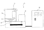
図2にトナー処理装置1の概略図を示す。 FIG. 2 shows a schematic view of the toner processing device 1.
トナー処理装置1は、処理室(処理槽)10、舞上げ手段としての撹拌羽根20、回転体30、駆動モータ50、及び制御部60で構成されている。処理室10は、トナー粒子及び外添剤を含む被処理物を収容するためのものである。そして、撹拌羽根20は、処理室内における回転体30の下方となる処理室10の底部に回転可能に設けられている。また、回転体30は、撹拌羽根20よりも上方で回転可能に設けられている。
The toner processing apparatus 1 includes a processing chamber (processing tank) 10, a
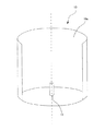
図3に処理室10の概略図を示す。図3では、説明の便宜上、処理室10の内周面(内壁)10aを一部切断した状態を示している。本実施形態において処理室10は略平らな底部を持った円筒形の容器であり、底部の略中心に撹拌羽根20や回転体30を取り付けるための駆動軸11を備えている。
FIG. 3 shows a schematic view of the
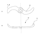
図4に舞上げ手段としての撹拌羽根20の概略図を示す。図4(a)に上面図、図4(b)に側面図を示している。本実施形態において、撹拌羽根20は、回転することで、トナー粒子及び外添剤を含む被処理物を処理室10内で舞上げ可能に構成されている。撹拌羽根20は、回転中心から外側(径方向の外向き(外径方向)、外径側)に向かって伸びる羽根部21を有し、羽根部21の先端が被処理物を舞上げるように跳ねあげ形状をしている。撹拌羽根20は、処理室10の底部の駆動軸11に固定される。図では、駆動軸11の回転方向を矢印Rで示している。撹拌羽根20の回転により、被処理物は処理室10内で撹拌羽根20と同じ方向に回転しながら上昇し、やがて重力によって下降してくる。このようにして被処理物は均一に混合される。
FIG. 4 shows a schematic view of the
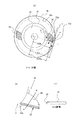
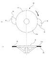
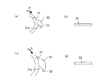
図1に回転体30の概略図を示す。図1(a)は処理室10内に設置された回転体30を示す上面図、図1(b)は回転体30の要部を示す斜視図、図1(c)は図1(b)のA−A断面を示す図である。図5(a)は回転体30の上面図、図5(b)は側面図である。
FIG. 1 shows a schematic diagram of the
本実施形態において回転体30は、処理室10内で撹拌羽根20よりも上方にあって、撹拌羽根20と同じ駆動軸11に固定され、撹拌羽根20と同じ方向(矢印R方向)に回転する。
In the present embodiment, the rotating
回転体30は、回転体本体31と、回転体30の回転により被処理物に衝突して該被処理物を処理する処理面33を備えた処理部32で構成されている。処理面33は、回転体本体31の外周面31aから外径方向に延び、かつ、処理面33のうち回転体本体31から離れた領域の方が、該領域より回転体本体31に近い領域より、回転体30の回転方向下流側に位置するように形成されている。
The rotating
回転体30の回転により、被処理物と処理面33が衝突することによって外添処理が行われる。
The rotation of the
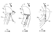
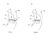
図6,7は、処理面33の機能について説明するための図である。そして、処理面33において、後述する角度θの大きさが、θ<90度となる従来の場合を図6(a)に示し、θ>90度とした本実施形態の場合を図6(b)に示し、θ>130度の場合を図6(c)に示している。また、回転体の処理面が存在する位置における、回転軸に直交する方向での処理室の断面について、処理室の内周面で形成される円の半径をL、処理室の内周面で形成される円の中心から処理面33の回転体本体から最も離れた端部位置までの距離をrとしたとき、r<0.80Lの場合を図7(a)に示し、r≧0.80Lの場合を図7(b)に示している。なお、説明の便宜上、従来例や比較例を示す図においても、本実施形態と同様の構成部材には、本実施形態と同じ符号を付している。
6 and 7 are diagrams for explaining the function of the
本発明者らは上記トナー処理装置の処理面33が、処理面33の内、回転体本体31から離れた領域の方が、回転体本体31に近い領域よりも、回転体30の回転方向の下流側に位置するように形成されている必要があることを見出した。
The present inventors have found that the
処理面が前記の形態であると、図6(b)に示すように、旋回している被処理物を処理面33で一度処理した後に、該被処理物を処理面33の進行方向に打ち返す(処理面33で処理すると共に打ち返す)ことができると考えられる。被処理物が処理面33の進行方向に打ち返されれば、回転体30の回転時における処理面33の通過領域内に被処理物を位置させる(留めておく)ことができ、回転移動する処理面33は、被処理物を繰り返し処理することができる。
When the processing surface has the above-described form, as shown in FIG. 6B, after the rotating processing object is once processed by the
このとき、処理面33は、回転体本体31の外周面31aから外径方向に延びるように設けられているので、図6(b)に矢印で示す被処理物Tの軌跡のように、被処理物を処理面33と外周面31aとの間に巻き込む(流れ込ませる)ことができる。これにより、被処理物を処理面33の内径側から逃がすことなく、処理面33の進行方向に打ち返さすことができる。従ってより確実に処理面33で被処理物を繰り返し処理することができるようになる。
At this time, since the
このように処理面が前記の形態であると、衝突回数を多くすることでより短時間での処理が可能となり、外添剤の拡散性を保持したまま固着させることが可能となり好ましい。 When the treated surface has the above-described form, the treatment can be performed in a shorter time by increasing the number of collisions, and the external additive can be fixed while maintaining the diffusivity.
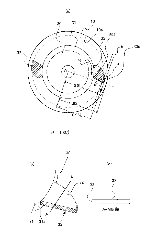
また、該回転体本体から最も離れた処理面33の端部位置が、処理室の内周面で形成される上記の円の半径の80%となる位置より内周面側(半径方向外側)であり、且つ該処理室の内周面に接触しない位置であるとより好ましい。即ち、0.80L≦r<Lであることが好ましい。また、処理面33の端部位置は、処理室の内周面で形成される上記の円の半径の99%となる位置より回転体本体側である(r≦0.99L)ことが好ましい。
Further, the end position of the
処理面33の端部位置が上記範囲にあると処理面33の高さ(駆動軸11の回転軸方向の長さ)が同じ場合処理面積がより大きくなるため、旋回している被処理物を数多く処理することができ、より短時間で処理が可能となるため好ましい。
When the end position of the
また処理面33は回転運動をしていることから、処理面33が処理室10の内周面10aに近づくほど、処理面33の先端部分の周速が増加する。処理面33の周速が増すと被処理物への衝突時の処理エネルギーが大きくなるため、より短時間で外添剤の固着を達成させることが可能となるため好ましい。
Further, since the
更に、処理面33の回転体本体31に最も近い第1部位と、該処理面33上において処理室の内周面で形成される上記の円の中心から0.80Lの位置に位置する第2部位とを結ぶ線を線aとし、上記の円と同心円であって、第2部位を通る円の第2部位における接線を線bとしたとき、線aと線bとのなす角のうち回転方向下流側の角(角度θ)の大きさが、90度より大きく130度以下であることが好ましい。
Furthermore, the first portion of the
角度θが前記範囲内であると、図6(b)に示す様に、被処理物が外側に逃げることなく処理面33と繰り返し衝突し、短時間で多くの衝突回数を達成することができ、外添剤の拡散性を保持したまま固着させることが可能となり好ましい。
When the angle θ is within the above range, as shown in FIG. 6B, the object to be processed repeatedly collides with the
また処理面33の回転体本体31に最も近い第1部位が、処理室の内周面で形成される上記の円の半径の60%になる位置より内周面側にあることが好ましい。即ち、処理室の内周面で形成される円の中心から該処理面の該回転体本体に最も近い第一部位までの距離をRとしたとき、R≧0.60Lを満たすことが好ましい。
Further, it is preferable that the first portion of the
第1部位までの長さと端部までの長さが上記範囲内であると、処理面33の全体が十分な周速を持ち、被処理物への衝突時の処理エネルギーが大きくなり、より短時間で外添剤の固着を達成させることが可能となるため好ましい。また処理面33の第1部位と端部それぞれの周速が近くなり、被処理物のより均一な処理が可能となるため好ましい。
When the length to the first portion and the length to the end are within the above range, the
本実施形態では、図7(b)に示すように、r<0.80Lの処理面(図7(a))に比べ処理面33が外径方向に長くなる(r≧0.80L)ように構成されている。このため、処理面33の高さ(駆動軸11の回転軸方向の長さ)が同じ(トナー処理装置のサイズが同じ)場合、処理面積が大きくなるため、旋回している被処理物を数多く処理することができる。また、処理面33は回転運動していることから、処理面33が、処理室10の内周面10aに近づくほど、処理面33の先端(外径側の端部、外径端)部分の周速が速くなる。
In the present embodiment, as shown in FIG. 7B, the
処理面33の周速が速くなると、被処理物への衝突力が大きくなるため、被処理物を解砕する効果が大きくなると考えられる。
It is considered that when the peripheral speed of the
一方、図7(a)に示す構成の場合、処理面33の外径方向の長さが図7(b)に示す構成よりも短いため、被処理物に衝突する確率が低くなると考えられる。また、処理室10の内周面10a近く(図7(a)の領域c)に処理面33が存在しないため、回転している処理面33の先端部分の周速は、図7(b)に示す構成の場合の周速と比べて遅くなるため、被処理物を解砕する効果が小さくなると考えられる。
On the other hand, in the case of the configuration shown in FIG. 7A, the length of the
以下に本発明のトナーの構成を示す。 The constitution of the toner of the present invention is shown below.
本発明のトナーは、結着樹脂、着色剤及び離型剤を含有するトナー粒子と、有機無機複合微粒子及び無機微粒子aと、を有する。その他、必要に応じて電荷制御剤や磁性体などを含有していてもよい。 The toner of the present invention has toner particles containing a binder resin, a colorant, and a release agent, and organic-inorganic composite fine particles and inorganic fine particles a. In addition, a charge control agent, a magnetic material or the like may be contained if necessary.
本発明の有機無機複合微粒子の無機微粒子bは、シリカ又は金属酸化物微粒子であることが好ましい。有機無機複合微粒子の無機微粒子bがシリカ又は金属酸化物微粒子であると、帯電性に優れまたトナーに充分な流動性能を付与することができ、外添剤として良好に機能するため好ましい。 The inorganic fine particles b of the organic-inorganic composite fine particles of the present invention are preferably silica or metal oxide fine particles. It is preferable that the inorganic fine particles b of the organic-inorganic composite fine particles are silica or metal oxide fine particles because they are excellent in chargeability and can impart sufficient flowability to the toner and function well as an external additive.
有機無機複合微粒子は、例えばWO 2013/063291の実施例の記載に従って製造することができる。 The organic-inorganic composite fine particles can be produced, for example, according to the description in Examples of WO 2013/063291.
有機無機複合微粒子の個数平均粒径やSF−1、SF−2は、有機無機複合微粒子に使用する無機微粒子bの粒径や、無機微粒子bと樹脂の量比を変えることで適宜コントロールすることができる。 The number average particle diameter and SF-1 and SF-2 of the organic-inorganic composite fine particles are appropriately controlled by changing the particle diameter of the inorganic fine particles b used in the organic-inorganic composite fine particles and the ratio of the amount of the inorganic fine particles b to the resin. You can
本発明の有機無機複合微粒子のトナー粒子中の添加量は、好ましくはトナー粒子100質量部に対して、0.1質量部以上4.0質量部以下である。 The addition amount of the organic-inorganic composite fine particles of the invention in the toner particles is preferably 0.1 part by mass or more and 4.0 parts by mass or less with respect to 100 parts by mass of the toner particles.
本発明のトナーは有機無機複合微粒子に加えて、帯電性能や流動性能を補助するための無機微粒子aを有する。 The toner of the present invention has, in addition to the organic-inorganic composite fine particles, the inorganic fine particles a for assisting the charging performance and the flow performance.
無機微粒子aとしては、例えば、フッ化ビニリデン微粉末、ポリテトラフウルオロエチレン微粉末の如きフッ素系樹脂粉末;湿式製法シリカ、乾式製法シリカの如き微粉末シリカ、微粉末酸化チタン、微粉末アルミナ、それらをシラン化合物、チタンカップリング剤、シリコーンオイルにより表面処理を施した処理シリカ;酸化亜鉛、酸化スズの如き酸化物;チタン酸ストロンチウムやチタン酸バリウム、チタン酸カルシウム、ジルコン酸ストロンチウムやジルコン酸カルシウムの如き複酸化物;炭酸カルシウム及び、炭酸マグネシウムの如き炭酸塩化合物が挙げられる。 Examples of the inorganic fine particles a include fluorine-based resin powders such as vinylidene fluoride fine powder and polytetrafluoroethylene fine powder; fine powder silica such as wet process silica and dry process silica, fine powder titanium oxide, and fine powder alumina. , Silica treated with surface treatment with silane compound, titanium coupling agent, silicone oil; oxides such as zinc oxide and tin oxide; strontium titanate and barium titanate, calcium titanate, strontium zirconate and zirconate Double oxides such as calcium; calcium carbonate and carbonate compounds such as magnesium carbonate.
好ましくはケイ素ハロゲン化合物の蒸気相酸化により生成された微粉末であり、いわゆる乾式法シリカ又はヒュームドシリカと称されるものである。例えば、四塩化ケイ素ガスの酸水素焔中における熱分解酸化反応を利用するもので、基礎となる反応式は次のようなものである。
SiCl4+2H2+O2→SiO2+4HCl
A fine powder produced by vapor phase oxidation of a silicon halogen compound is preferable, and so-called dry process silica or fumed silica is called. For example, the thermal decomposition oxidation reaction of silicon tetrachloride gas in oxyhydrogen flame is utilized, and the basic reaction formula is as follows.
SiCl 4 +2H 2 +O 2 →SiO 2 +4HCl
この製造工程において、塩化アルミニウム又は塩化チタン等の他の金属ハロゲン化合物をケイ素ハロゲン化合物と共に用いることによってシリカと他の金属酸化物の複合微粉体を得ることも可能であり、シリカとしてはそれらも包含する。 In this manufacturing process, it is possible to obtain a composite fine powder of silica and another metal oxide by using another metal halogen compound such as aluminum chloride or titanium chloride together with a silicon halogen compound, and silica also includes them. To do.
ケイ素ハロゲン化合物の蒸気相酸化により生成された市販のシリカ微粉体としては、例えば、以下のものを例示できる。AEROSIL(日本アエロジル社)130、200、300、380、TT600、MOX170、MOX80、COK84、CAB−O−SIL(CABOT Co.社)M−5、MS−7、MS−75、HS−5、EH−5、Wacker HDK N 20(WACKER−CHEMIE GMBH社)V15、N20E、T30、T40、D−C Fine Silica(ダウコーニングCo.社)、Fransol(Fransil社)。 Examples of commercially available silica fine powder produced by vapor-phase oxidation of a silicon halogen compound include the following. AEROSIL (Japan Aerosil Co., Ltd.) 130, 200, 300, 380, TT600, MOX170, MOX80, COK84, CAB-O-SIL (CABOT Co.) M-5, MS-7, MS-75, HS-5, EH. -5, Wacker HDK N 20 (WACKER-CHEMIE GMBH) V15, N20E, T30, T40, D-C Fine Silica (Dow Corning Co.), Francol (Fransil).
さらには、本発明に用いられる無機微粒子aとしては、前記ケイ素ハロゲン化合物の気相酸化により生成されたシリカ微粉体に疎水化処理した処理シリカ微粉体がより好ましい。 Furthermore, as the inorganic fine particles a used in the present invention, a treated silica fine powder obtained by subjecting the silica fine powder produced by the vapor phase oxidation of the silicon halogen compound to a hydrophobic treatment is more preferable.
トナー粒子100質量部に対して、無機微粒子aの含有量は0.01質量部以上8質量部以下であることが好ましく、より好ましくは0.1質量部以上4質量部以下である。尚、無機微粒子aに該当する粒子が複数ある場合には、それらの合計量を含有量とみなす。 The content of the inorganic fine particles a is preferably 0.01 parts by mass or more and 8 parts by mass or less, and more preferably 0.1 parts by mass or more and 4 parts by mass or less with respect to 100 parts by mass of the toner particles. When there are a plurality of particles corresponding to the inorganic fine particles a, the total amount of them is regarded as the content.
本発明のトナー粒子に用いられる結着樹脂について記載する。 The binder resin used in the toner particles of the present invention will be described.
結着樹脂としては、ポリエステル樹脂、ビニル系樹脂、エポキシ樹脂、ポリウレタン樹脂が挙げられる。 Examples of the binder resin include polyester resin, vinyl resin, epoxy resin, and polyurethane resin.
ポリエステル系樹脂の組成は例えば以下の通りである。 The composition of the polyester resin is as follows, for example.
アルコール成分としては、以下のものが挙げられる。エチレングリコール、プロピレングリコール、1,3−ブタンジオール、1,4−ブタンジオール、2,3−ブタンジオール、ジエチレングリコール、トリエチレングリコール、1,5−ペンタンジオール、1,6−ヘキサンジオール、ネオペンチルグリコール、2−エチル−1,3−ヘキサンジオール、水素化ビスフェールA、芳香族ジオールとしては、下記式[2]で表わされるビスフェノール及びその誘導体、下記式[3]で示されるジオール類、が挙げられる。 Examples of the alcohol component include the following. Ethylene glycol, propylene glycol, 1,3-butanediol, 1,4-butanediol, 2,3-butanediol, diethylene glycol, triethylene glycol, 1,5-pentanediol, 1,6-hexanediol, neopentyl glycol Examples of 2-ethyl-1,3-hexanediol, hydrogenated bisphenol A, and aromatic diol include bisphenol represented by the following formula [2] and its derivatives, and diols represented by the following formula [3]. To be
酸成分としては、以下のものが挙げられる。フタル酸、テレフタル酸、イソフタル酸、無水フタル酸の如きベンゼンジカルボン酸類またはその無水物;こはく酸、アジピン酸、セバシン酸、アゼライン酸の如きアルキルジカルボン酸類またはその無水物、またさらに炭素数6以上18以下のアルキル基またはアルケニル基で置換されたこはく酸もしくはその無水物;フマル酸、マレイン酸、シトラコン酸、イタコン酸の如き不飽和ジカルボン酸またはその無水物。3価以上の多価アルコール成分としては、ソルビトール、1,2,3,6−ヘキサンテトロール、1,4−ソルビタン、ペンタエリスリトール、ジペンタエリスリトール、トリペンタエリスリトール、1,2,4−ブタントリオール、1,2,5−ペンタントリオール、グリセロール、2−メチルプロパントリオール、2−メチル−1,2,4−ブタントリオール、トリメチロールエタン、トリメチロールプロパン、1,3,5−トリヒドロキシベンゼンが挙げられる。 Examples of the acid component include the following. Benzenedicarboxylic acids such as phthalic acid, terephthalic acid, isophthalic acid and phthalic anhydride or their anhydrides; alkyldicarboxylic acids such as succinic acid, adipic acid, sebacic acid, azelaic acid or their anhydrides, and further having 6 or more carbon atoms 18 Succinic acid or its anhydride substituted with the following alkyl groups or alkenyl groups; unsaturated dicarboxylic acids or their anhydrides such as fumaric acid, maleic acid, citraconic acid and itaconic acid. Examples of the trihydric or higher polyhydric alcohol component include sorbitol, 1,2,3,6-hexanetetrol, 1,4-sorbitan, pentaerythritol, dipentaerythritol, tripentaerythritol, and 1,2,4-butanetriol. , 1,2,5-pentanetriol, glycerol, 2-methylpropanetriol, 2-methyl-1,2,4-butanetriol, trimethylolethane, trimethylolpropane, 1,3,5-trihydroxybenzene. To be
三価以上の多価カルボン酸成分としては、トリメリット酸、ピロメリット酸、1,2,4−ベンゼントリカルボン酸、1,2,5−ベンゼントリカルボン酸、2,5,7−ナフタレントリカルボン酸、1,2,4−ナフタレントリカルボン酸、1,2,4−ブタントリカルボン酸、1,2,5−ヘキサントリカルボン酸、1,3−ジカルボキシル−2−メチル−2−メチレンカルボキシプロパン、テトラ(メチレンカルボキシル)メタン、1,2,7,8−オクタンテトラカルボン酸、エンポール三量体酸、及びこれらの無水物が挙げられる。 Examples of the trivalent or higher polycarboxylic acid component include trimellitic acid, pyromellitic acid, 1,2,4-benzenetricarboxylic acid, 1,2,5-benzenetricarboxylic acid, 2,5,7-naphthalenetricarboxylic acid, 1,2,4-naphthalenetricarboxylic acid, 1,2,4-butanetricarboxylic acid, 1,2,5-hexanetricarboxylic acid, 1,3-dicarboxyl-2-methyl-2-methylenecarboxypropane, tetra(methylene Carboxyl)methane, 1,2,7,8-octane tetracarboxylic acid, employer trimer acid, and their anhydrides.
上記ポリエステル樹脂は通常一般に知られている縮重合によって得られる。 The polyester resin is usually obtained by generally known polycondensation.
ビニル系樹脂成分を生成する為のビニル系モノマーとしては、次の様なものが挙げられる。 Examples of the vinyl-based monomer for producing the vinyl-based resin component include the following.
スチレン;o−メチルスチレン、m−メチルスチレン、p−メチルスチレン、p−メトキシスチレン、p−フェニルスチレン、p−クロルスチレン、3,4−ジクロルスチレン、p−エチルスチレン、2,4−ジメチルスチレン、p−n−ブチルスチレン、p−tert−ブチルスチレン、p−n−ヘキシルスチレン、p−n−オクチルスチレン、p−n−ノニルスチレン、p−n−デシルスチレン、p−n−ドデシルスチレンの如きスチレン及びその誘導体;エチレン、プロピレン、ブチレン、イソブチレンの如き不飽和モノオレフィン類;ブタジエン、イソプレンの如き不飽和ポリエン類;塩化ビニル、塩化ビニリデン、臭化ビニル、フッ化ビニルの如きハロゲン化ビニル類;酢酸ビニル、プロピオン酸ビニル、ベンゾエ酸ビニルの如きビニルエステル類;メタクリル酸メチル、メタクリル酸エチル、メタクリル酸プロピル、メタクリル酸n−ブチル、メタクリル酸イソブチル、メタクリル酸n−オクチル、メタクリル酸ドデシル、メタクリル酸2−エチルヘキシル、メタクリル酸ステアリル、メタクリル酸フェニル、メタクリル酸ジメチルアミノエチル、メタクリル酸ジエチルアミノエチルの如きα−メチレン脂肪族モノカルボン酸エステル類;アクリル酸メチル、アクリル酸エチル、アクリル酸n−ブチル、アクリル酸イソブチル、アクリル酸プロピル、アクリル酸n−オクチル、アクリル酸ドデシル、アクリル酸2−エチルヘキシル、アクリル酸ステアリル、アクリル酸2−クロルエチル、アクリル酸フェニルの如きアクリル酸エステル類;ビニルメチルエーテル、ビニルエチルエーテル、ビニルイソブチルエーテルの如きビニルエーテル類;ビニルメチルケトン、ビニルヘキシルケトン、メチルイソプロペニルケトンの如きビニルケトン類;N−ビニルピロール、N−ビニルカルバゾール、N−ビニルインドール、N−ビニルピロリドンの如きN−ビニル化合物;ビニルナフタリン類;アクリロニトリル、メタクリロニトリル、アクリルアミドの如きアクリル酸もしくはメタクリル酸誘導体。 Styrene: o-methylstyrene, m-methylstyrene, p-methylstyrene, p-methoxystyrene, p-phenylstyrene, p-chlorostyrene, 3,4-dichlorostyrene, p-ethylstyrene, 2,4-dimethyl Styrene, pn-butylstyrene, p-tert-butylstyrene, pn-hexylstyrene, pn-octylstyrene, pn-nonylstyrene, pn-decylstyrene, pn-dodecylstyrene And their derivatives; unsaturated monoolefins such as ethylene, propylene, butylene and isobutylene; unsaturated polyenes such as butadiene and isoprene; vinyl halides such as vinyl chloride, vinylidene chloride, vinyl bromide and vinyl fluoride. Vinyl esters such as vinyl acetate, vinyl propionate and vinyl benzoate; methyl methacrylate, ethyl methacrylate, propyl methacrylate, n-butyl methacrylate, isobutyl methacrylate, n-octyl methacrylate, dodecyl methacrylate, Α-Methylene aliphatic monocarboxylic acid esters such as 2-ethylhexyl methacrylate, stearyl methacrylate, phenyl methacrylate, dimethylaminoethyl methacrylate, diethylaminoethyl methacrylate; methyl acrylate, ethyl acrylate, n-butyl acrylate Acrylic acid esters such as isobutyl acrylate, propyl acrylate, n-octyl acrylate, dodecyl acrylate, 2-ethylhexyl acrylate, stearyl acrylate, 2-chloroethyl acrylate, phenyl acrylate; vinyl methyl ether, vinyl Vinyl ethers such as ethyl ether and vinyl isobutyl ether; Vinyl ketones such as vinyl methyl ketone, vinyl hexyl ketone and methyl isopropenyl ketone; N such as N-vinyl pyrrole, N-vinyl carbazole, N-vinyl indole and N-vinyl pyrrolidone -Vinyl compounds; vinyl naphthalenes; acrylic acid or methacrylic acid derivatives such as acrylonitrile, methacrylonitrile and acrylamide.
さらに、以下のものが挙げられる。マレイン酸、シトラコン酸、イタコン酸、アルケニルコハク酸、フマル酸、メサコン酸の如き不飽和二塩基酸;マレイン酸無水物、シトラコン酸無水物、イタコン酸無水物、アルケニルコハク酸無水物の如き不飽和二塩基酸無水物;マレイン酸メチルハーフエステル、マレイン酸エチルハーフエステル、マレイン酸ブチルハーフエステル、シトラコン酸メチルハーフエステル、シトラコン酸エチルハーフエステル、シトラコン酸ブチルハーフエステル、イタコン酸メチルハーフエステル、アルケニルコハク酸メチルハーフエステル、フマル酸メチルハーフエステル、メサコン酸メチルハーフエステルの如き不飽和二塩基酸のハーフエステル;ジメチルマレイン酸、ジメチルフマル酸の如き不飽和二塩基酸エステル;アクリル酸、メタクリル酸、クロトン酸、ケイヒ酸の如きα,β−不飽和酸;クロトン酸無水物、ケイヒ酸無水物の如きα,β−不飽和酸無水物、該α,β−不飽和酸と低級脂肪酸との無水物;アルケニルマロン酸、アルケニルグルタル酸、アルケニルアジピン酸、これらの酸無水物及びこれらのモノエステルの如きカルボキシル基を有するモノマー。 Further, the following may be mentioned. Unsaturated dibasic acids such as maleic acid, citraconic acid, itaconic acid, alkenylsuccinic acid, fumaric acid, mesaconic acid; unsaturated compounds such as maleic anhydride, citraconic anhydride, itaconic anhydride, alkenylsuccinic anhydride Dibasic acid anhydrides: maleic acid methyl half ester, maleic acid ethyl half ester, maleic acid butyl half ester, citraconic acid methyl half ester, citraconic acid ethyl half ester, citraconic acid butyl half ester, itaconic acid methyl half ester, alkenylsuccinic acid Unsaturated dibasic acid half esters such as acid methyl half ester, fumaric acid methyl half ester, mesaconic acid methyl half ester; unsaturated dibasic acid esters such as dimethyl maleic acid and dimethyl fumaric acid; acrylic acid, methacrylic acid, croton Acids, α,β-unsaturated acids such as cinnamic acid; α,β-unsaturated acid anhydrides such as crotonic acid anhydride and cinnamic acid anhydride, anhydrides of the α,β-unsaturated acids and lower fatty acids Monomers having a carboxyl group such as alkenylmalonic acid, alkenylglutaric acid, alkenyladipic acid, their acid anhydrides and their monoesters.
さらに、2−ヒドロキシエチルアクリレート、2−ヒドロキシエチルメタクリレート、2−ヒドロキシプロピルメタクリレートの如きアクリル酸またはメタクリル酸エステル類;4−(1−ヒドロキシ−1−メチルブチル)スチレン、4−(1−ヒドロキシ−1−メチルヘキシル)スチレンの如きヒドロキシ基を有するモノマーが挙げられる。 Further, acrylic acid or methacrylic acid esters such as 2-hydroxyethyl acrylate, 2-hydroxyethyl methacrylate and 2-hydroxypropyl methacrylate; 4-(1-hydroxy-1-methylbutyl)styrene, 4-(1-hydroxy-1) -Methylhexyl) styrene, such as a monomer having a hydroxy group.
本発明のトナーにおいて、ビニル系樹脂或いはビニル系重合体ユニットは、ビニル基を2個以上有する架橋剤で架橋された架橋構造を有してもよい。この場合に用いられる架橋剤としては、以下のものが挙げられる。芳香族ジビニル化合物(ジビニルベンゼン、ジビニルナフタレン);アルキル鎖で結ばれたジアクリレート化合物類(エチレングリコールジアクリレート、1,3−ブチレングリコールジアクリレート、1,4−ブタンジオールジアクリレート、1,5−ペンタンジオールアクリレート、1,6−へキサンジオールジアクリレート、ネオペンチルグリコールジアクリレート、及び以上の化合物のアクリレートをメタクリレートに代えたもの);エーテル結合を含むアルキル鎖で結ばれたジアクリレート化合物類(例えば、ジエチレングリコールジアクリレート、トリエチレングリコールジアクリレート、テトラエチレングリコールジアクリレート、ポリエチレングリコール#400ジアクリレート、ポリエチレングリコール#600ジアクリレート、ジプロピレングリコールジアクリレート、及び以上の化合物のアクリレー卜をメタクリレートに代えたもの);芳香族基及びエーテル結合を含む鎖で結ばれたジアクリレート化合物類[ポリオキシエチレン(2)−2,2−ビス(4ヒドロキシフェニル)プロパンジアクリレート、ポリオキシエチレン(4)−2,2−ビス(4ヒドロキシフェニル)プロパンジアクリレート、及び以上の化合物のアクリレートをメタクリレートに代えたもの];ポリエステル型ジアクリレート化合物類(日本化薬社製「MANDA」)。 In the toner of the present invention, the vinyl resin or vinyl polymer unit may have a crosslinked structure crosslinked with a crosslinking agent having two or more vinyl groups. Examples of the cross-linking agent used in this case include the following. Aromatic divinyl compounds (divinylbenzene, divinylnaphthalene); Diacrylate compounds linked by an alkyl chain (ethylene glycol diacrylate, 1,3-butylene glycol diacrylate, 1,4-butanediol diacrylate, 1,5- Pentanediol acrylate, 1,6-hexanediol diacrylate, neopentyl glycol diacrylate, and the above compounds in which acrylate is replaced with methacrylate); diacrylate compounds linked by an alkyl chain containing an ether bond (for example, , Diethylene glycol diacrylate, triethylene glycol diacrylate, tetraethylene glycol diacrylate, polyethylene glycol #400 diacrylate, polyethylene glycol #600 diacrylate, dipropylene glycol diacrylate, and any of the above compounds in which the acrylate is replaced with methacrylate. ); Diacrylate compounds linked by a chain containing an aromatic group and an ether bond [polyoxyethylene (2)-2,2-bis(4hydroxyphenyl)propane diacrylate, polyoxyethylene (4)-2, 2-bis(4hydroxyphenyl)propanediacrylate, and those in which the acrylates of the above compounds are replaced by methacrylates]; polyester type diacrylate compounds (“MANDA” manufactured by Nippon Kayaku Co., Ltd.).
多官能の架橋剤としては、以下のものが挙げられる。ペンタエリスリトールトリアクリレート、トリメチロールエタントリアクリレート、トリメチロールプロパントリアクリレート、テトラメチロールメタンテトラアクリレート、オリゴエステルアクリレート、及び以上の化合物のアクリレートをメタクリレートに代えたもの;トリアリルシアヌレート、トリアリルトリメリテート。 The following are mentioned as a polyfunctional crosslinking agent. Pentaerythritol triacrylate, trimethylol ethane triacrylate, trimethylol propane triacrylate, tetramethylol methane tetraacrylate, oligoester acrylate, and compounds in which the acrylates of the above compounds are replaced by methacrylates; triallyl cyanurate, triallyl trimellitate ..
これらの架橋剤は、他のモノマー成分100質量部に対して、0.01質量部以上10.00質量部以下用いられることが好ましく、さらに好ましくは0.03質量部以上5.00質量部以下である。 These crosslinking agents are preferably used in an amount of 0.01 parts by mass or more and 10.00 parts by mass or less, and more preferably 0.03 parts by mass or more and 5.00 parts by mass or less, relative to 100 parts by mass of the other monomer components. Is.
これらの架橋剤のうち、樹脂成分に低温定着性、耐オフセット性の点から好適に用いられるものとして、芳香族ジビニル化合物(特にジビニルベンゼン)、芳香族基及びエーテル結合を含む鎖で結ばれたジアクリレート化合物類が挙げられる。 Among these cross-linking agents, those which are preferably used in the resin component from the viewpoint of low-temperature fixability and anti-offset property, are linked by a chain containing an aromatic divinyl compound (particularly divinylbenzene), an aromatic group and an ether bond. Diacrylate compounds may be mentioned.
上記ビニル系樹脂或いはビニル系重合体ユニットの重合に用いられる重合開始剤としては、以下のものが挙げられる。2,2’−アゾビスイソブチロニトリル、2,2’−アゾビス(4−メトキシ−2,4−ジメチルバレロニトリル)、2,2’−アゾビス(2,4−ジメチルバレロニトリル)、2,2’−アゾビス(2−メチルブチロニトリル)、ジメチル−2,2’−アゾビスイソブチレート、1,1’−アゾビス(1−シクロヘキサンカルボニトリル)、2−(カーバモイルアゾ)−イソブチロニトリル、2,2’−アゾビス(2,4,4−トリメチルペンタン)、2−フェニルアゾ−2,4−ジメチル−4−メトキシバレロニトリル、2,2−アゾビス(2−メチルプロパン)、メチルエチルケトンパーオキサイド、アセチルアセトンパ−オキサイド、シクロヘキサノンパーオキサイドの如きケトンパーオキサイド類、2,2−ビス(tert−ブチルパーオキシ)ブタン、tert−ブチルハイドロパーオキサイド、クメンハイドロパーオキサイド、1,1,3,3−テトラメチルブチルハイドロパーオキサイド、ジ−tert−ブチルパーオキサイド、tert−ブチルクミルパーオキサイド、ジクミルパーオキサイド、α,α’−ビス(tert−ブチルパーオキシイソプロピル)ベンゼン、イソブチルパーオキサイド、オクタノイルパーオキサイド、デカノイルパーオキサイド、ラウロイルパーオキサイド、3,5,5−トリメチルヘキサノイルパーオキサイド、ベンゾイルパーオキサイド、m−トリオイルパーオキサイド、ジ−イソプロピルパーオキシジカーボネート、ジ−2−エチルヘキシルパーオキシジカーボネート、ジ−n−プロピルパーオキシジカーボネート、ジ−2−エトキシエチルパーオキシカーボネート、ジメトキシイソプロピルパーオキシジカーボネート、ジ(3−メチル−3−メトキシブチル)パーオキシカーボネート、アセチルシクロヘキシルスルホニルパーオキサイド、tert−ブチルパーオキシアセテート、tert−ブチルパーオキシイソブチレート、tert−ブチルパーオキシネオデカノエート、tert−ブチルパーオキシ2−エチルヘキサノエート、tert−ブチルパーオキシラウレート、tert−ブチルパーオキシベンゾエート、tert−ブチルパーオキシイソプロピルカーボネート、ジ−tert−ブチルパーオキシイソフタレート、tert−ブチルパーオキシアリルカーボネート、tert−アミルパーオキシ2−エチルヘキサノエート、ジ−tert−プチルパーオキシヘキサハイドロテレフタレート、ジ−tert−ブチルパーオキシアゼレート。 Examples of the polymerization initiator used for polymerization of the vinyl resin or vinyl polymer unit include the following. 2,2'-azobisisobutyronitrile, 2,2'-azobis(4-methoxy-2,4-dimethylvaleronitrile), 2,2'-azobis(2,4-dimethylvaleronitrile), 2, 2'-azobis(2-methylbutyronitrile), dimethyl-2,2'-azobisisobutyrate, 1,1'-azobis(1-cyclohexanecarbonitrile), 2-(carbamoylazo)-isobutyronitrile , 2,2'-azobis(2,4,4-trimethylpentane), 2-phenylazo-2,4-dimethyl-4-methoxyvaleronitrile, 2,2-azobis(2-methylpropane), methyl ethyl ketone peroxide, Acetoneacetone peroxide, ketone peroxides such as cyclohexanone peroxide, 2,2-bis(tert-butylperoxy)butane, tert-butyl hydroperoxide, cumene hydroperoxide, 1,1,3,3-tetra Methyl butyl hydroperoxide, di-tert-butyl peroxide, tert-butyl cumyl peroxide, dicumyl peroxide, α,α′-bis(tert-butylperoxyisopropyl)benzene, isobutyl peroxide, octanoyl peroxide , Decanoyl peroxide, lauroyl peroxide, 3,5,5-trimethylhexanoyl peroxide, benzoyl peroxide, m-trioyl peroxide, di-isopropyl peroxydicarbonate, di-2-ethylhexyl peroxydicarbonate , Di-n-propylperoxydicarbonate, di-2-ethoxyethylperoxycarbonate, dimethoxyisopropylperoxydicarbonate, di(3-methyl-3-methoxybutyl)peroxycarbonate, acetylcyclohexylsulfonyl peroxide, tert. -Butyl peroxyacetate, tert-butyl peroxyisobutyrate, tert-butyl peroxy neodecanoate, tert-butyl peroxy 2-ethylhexanoate, tert-butyl peroxylaurate, tert-butyl peroxy Benzoate, tert-butyl peroxyisopropyl carbonate, di-tert-butyl peroxyisophthalate, tert-butyl peroxyallyl carbonate, tert-amyl peroxy 2-ethylhexanoate, di-tert-butyl peroxy Oxyhexahydroterephthalate, di-tert-butylperoxyazelate.
本発明に用いられる離型剤には次のようなものがある。例えばポリオレフィン共重合物、ポリオレフィンワックス、マイクロクリスタリンワックス、パラフィンワックス、フィッシャートロプシュワックスの如き脂肪族炭化水素系ワックスが挙げられる。また、これらの離型剤を、プレス発汗法、溶剤法、再結晶法、真空蒸留法、超臨界ガス抽出法又は融液晶析法を用いて分子量分布をシャープにしたものなどがある。離型剤として使用できる離型剤の具体的な例としては、サゾールH1、H2、C80、C105、C77(シューマン・サゾール社)、HNP−1、HNP−3、HNP−9、HNP−10、HNP−11、HNP−12(日本精鑞株式会社)、ユニリン(登録商標)350、425、550、700、ユニシッド(登録商標)、ユニシッド(登録商標)350、425、550、700(東洋ペトロライト社)が挙げられる。 The release agents used in the present invention are as follows. Examples thereof include polyolefin hydrocarbons, polyolefin wax, microcrystalline wax, paraffin wax, and aliphatic hydrocarbon wax such as Fischer-Tropsch wax. In addition, there is a release agent having a sharp molecular weight distribution obtained by a press sweating method, a solvent method, a recrystallization method, a vacuum distillation method, a supercritical gas extraction method, or a fused liquid crystal deposition method. Specific examples of the release agent that can be used as the release agent include Sazole H1, H2, C80, C105, C77 (Schumann Sazol Co.), HNP-1, HNP-3, HNP-9, HNP-10, HNP-11, HNP-12 (Nippon Seiren Co., Ltd.), Unilin (registered trademark) 350, 425, 550, 700, Unicid (registered trademark), Unicid (registered trademark) 350, 425, 550, 700 (Toyo Petrolite) Company).
本発明のトナーには、その帯電性を安定化させるために電荷制御剤を用いることが好ましい。電荷制御剤としては、本発明に用いられる結着樹脂の末端に存在する酸基あるいは水酸基と中心金属が相互作用し易い、有機金属錯体、キレート化合物が有効である。その例としては、モノアゾ金属錯体;アセチルアセトン金属錯体;芳香族ヒドロキシカルボン酸又は芳香族ジカルボン酸の金属錯体又は金属塩が挙げられる。 A charge control agent is preferably used in the toner of the present invention in order to stabilize its chargeability. As the charge control agent, an organic metal complex or a chelate compound in which an acid group or a hydroxyl group existing at the terminal of the binder resin used in the present invention and the central metal easily interact with each other is effective. Examples thereof include monoazo metal complex; acetylacetone metal complex; metal complex or metal salt of aromatic hydroxycarboxylic acid or aromatic dicarboxylic acid.
使用できる具体的な例としては、Spilon Black TRH、T−77、T−95(保土谷化学工業(株))、BONTRON(登録商標)S−34、S−44、S−54、E−84、E−88、E−89(オリエント化学工業(株))が挙げられる。また、電荷制御樹脂も上述の電荷制御剤と併用することもできる。 Specific examples that can be used include Spiron Black TRH, T-77, T-95 (Hodogaya Chemical Co., Ltd.), BONTRON (registered trademark) S-34, S-44, S-54, E-84. , E-88, E-89 (Orient Chemical Industry Co., Ltd.). The charge control resin can also be used in combination with the above charge control agent.
本発明のトナーは磁性体を含有しても良い。尚、磁性体は、着色剤の役割を兼ねることが一般的である。 The toner of the present invention may contain a magnetic material. Incidentally, the magnetic substance generally also serves as a coloring agent.
トナー中に含まれる磁性体としては、マグネタイト、ヘマタイト、フェライトのような酸化鉄、鉄、コバルト、ニッケルのような金属あるいはこれらの金属とアルミニウム、コバルト、銅、鉛、マグネシウム、スズ、亜鉛、アンチモン、ビスマス、カルシウム、マンガン、チタン、タングステン、バナジウムのような金属の合金およびその混合物が挙げられる。 The magnetic substance contained in the toner includes magnetite, hematite, iron oxides such as ferrite, metals such as iron, cobalt and nickel, or these metals and aluminum, cobalt, copper, lead, magnesium, tin, zinc and antimony. , Alloys of metals such as bismuth, calcium, manganese, titanium, tungsten, vanadium and mixtures thereof.
これらの磁性体は個数平均粒子径が0.05μm以上2.0μm以下、好ましくは0.10μm以上0.50μm以下のものが好ましい。トナー中に含有させる量としては結着樹脂100質量部に対し30質量部以上120質量部以下、特に好ましくは結着樹脂100質量部に対し40質量部以上110質量部以下である。 The number average particle diameter of these magnetic materials is preferably 0.05 μm or more and 2.0 μm or less, more preferably 0.10 μm or more and 0.50 μm or less. The amount contained in the toner is 30 parts by mass or more and 120 parts by mass or less with respect to 100 parts by mass of the binder resin, and particularly preferably 40 parts by mass or more and 110 parts by mass or less with respect to 100 parts by mass of the binder resin.
着色剤としては周知慣用されているものを用いることができるが、例えば、黒色着色剤、イエロー着色剤、マゼンタ着色剤、シアン着色剤などを用いることができる。 Well-known and commonly used colorants can be used, and for example, black colorants, yellow colorants, magenta colorants, cyan colorants and the like can be used.
黒色着色剤としてカーボンブラック,グラフト化カーボンや以下に示すイエロー/マゼンタ/シアン着色剤を用い黒色に調色されたものが利用可能である。 As a black colorant, carbon black, grafted carbon, or a yellow/magenta/cyan colorant shown below, which is toned black, can be used.
イエロー着色剤としては、縮合アゾ化合物,イソインドリノン化合物,アンスラキノン化合物,アゾ金属錯体,メチン化合物,アリルアミド化合物に代表される化合物が挙げられる。 Examples of the yellow colorant include compounds represented by condensed azo compounds, isoindolinone compounds, anthraquinone compounds, azo metal complexes, methine compounds, and allylamide compounds.
マゼンタ着色剤としては、縮合アゾ化合物,ジケトピロロピロール化合物,アントラキノン,キナクリドン化合物,塩基染料レーキ化合物,ナフトール化合物,ベンズイミダゾロン化合物,チオインジゴ化合物,ペリレン化合物等が挙げられる。 Examples of magenta colorants include condensed azo compounds, diketopyrrolopyrrole compounds, anthraquinones, quinacridone compounds, basic dye lake compounds, naphthol compounds, benzimidazolone compounds, thioindigo compounds, and perylene compounds.
シアン着色剤としては、銅フタロシアニン化合物及びその誘導体,アントラキノン化合物,塩基染料レーキ化合物等が挙げられる。これらの着色剤は、単独又は混合し更には固溶体の状態で用いることができる。 Examples of cyan colorants include copper phthalocyanine compounds and their derivatives, anthraquinone compounds, and basic dye lake compounds. These colorants may be used alone or in combination, and may be used in the form of solid solution.
着色剤は、色相角、彩度、明度、耐候性、OHP透明性、トナー中への分散性のを考慮して選択される。該着色剤の添加量は、結着樹脂100質量部に対して、1質量部以上20質量部以下であることが好ましい。 The colorant is selected in consideration of hue angle, saturation, lightness, weather resistance, OHP transparency, and dispersibility in the toner. The addition amount of the colorant is preferably 1 part by mass or more and 20 parts by mass or less with respect to 100 parts by mass of the binder resin.
本発明に係るトナーは粉砕法によって作製されることが好ましい。粉砕法によって作製されたトナーは形状的に処理面と衝突した際のエネルギーを逃さず外添剤の処理に向けることが可能であるためである。 The toner according to the present invention is preferably produced by a pulverization method. This is because the toner produced by the pulverization method can be directed to the treatment of the external additive without releasing the energy when colliding with the treated surface in terms of shape.
粉砕法では、
(1)結着樹脂、着色剤及び離型剤、並びに必要に応じて磁性体粒子、及びその他の添加剤等を、ヘンシェルミキサー、ボールミルの如き混合機により充分に混合し、
(2)得られた混合物を二軸混練押出機、加熱ロール、ニーダー、エクストルーダーの如き熱混練機を用いて溶融混練し、
(3)冷却固化後、粉砕し、
(4)分級を行う
ことによって、トナー粒子を得ることができる。
In the grinding method,
(1) A binder resin, a colorant and a release agent, and optionally magnetic particles, and other additives are sufficiently mixed by a mixer such as a Henschel mixer or a ball mill,
(2) The obtained mixture is melt-kneaded using a heat kneader such as a twin-screw kneading extruder, a heating roll, a kneader, and an extruder,
(3) After cooling and solidifying, crushing,
(4) Toner particles can be obtained by performing classification.
またトナー粒子の形状及び表面性の制御のために、粉砕あるいは分級後に、表面処理工程を有することが好ましい。 Further, in order to control the shape and surface property of the toner particles, it is preferable to have a surface treatment step after pulverization or classification.
混合機としては、以下のものが挙げられる。ヘンシェルミキサー(日本コークス工業社製);スーパーミキサー(カワタ社製);リボコーン(大川原製作所社製);ナウターミキサー、タービュライザー、サイクロミックス(ホソカワミクロン社製);スパイラルピンミキサー(太平洋機工社製);レーディゲミキサー(マツボー社製)。 The following are mentioned as a mixer. Henschel mixer (manufactured by Nippon Coke Industry Co., Ltd.); Super mixer (manufactured by Kawata Co., Ltd.); Ribocon (manufactured by Okawara Seisakusho); Nauta mixer, turbulizer, cyclomix (manufactured by Hosokawa Micron); Spiral pin mixer (manufactured by Pacific Machinery Co., Ltd.) ); Ledige mixer (manufactured by Matsubo).
混練機としては、以下のものが挙げられる。KRCニーダー(栗本鉄工所社製);ブス・コ・ニーダー(Buss社製);TEM型押し出し機(東芝機械社製);TEX二軸混練機(日本製鋼所社製);PCM混練機(池貝鉄工所社製);三本ロールミル、ミキシングロールミル、ニーダー(井上製作所社製);ニーデックス(日本コークス工業社製);MS式加圧ニーダー、ニダールーダー(森山製作所社製);バンバリーミキサー(神戸製鋼所社製)。 Examples of the kneader include the following. KRC Kneader (manufactured by Kurimoto Iron Works); Bus Co Kneader (manufactured by Buss); TEM type extruder (manufactured by Toshiba Machine Co.); TEX twin-screw kneader (manufactured by Japan Steel Works); PCM kneader (Ikegai) Iron Rolling Co., Ltd.; Three Roll Mill, Mixing Roll Mill, Kneader (Inoue Seisakusho); Kneedex (Nippon Coke Industry Co., Ltd.); MS Pressure Kneader, Nider Ruder (Moriyama Seisakusho); Banbury Mixer (Kobe) Made by Steel Works).
粉砕機としては、以下のものが挙げられる。カウンタージェットミル、ミクロンジェット、イノマイザ(ホソカワミクロン社製);IDS型ミル、PJMジェット粉砕機(日本ニューマチック工業社製);クロスジェットミル(栗本鉄工所社製);ウルマックス(日曹エンジニアリング社製);SKジェット・オー・ミル(セイシン企業社製);クリプトロン(川崎重工業社製);ターボミル(ターボエ業社製);スーパーローター(日清エンジニアリング社製)。 The crusher includes the following. Counter jet mill, micron jet, inomizer (manufactured by Hosokawa Micron); IDS type mill, PJM jet crusher (manufactured by Nippon Pneumatic Mfg. Co.); Cross jet mill (manufactured by Kurimoto Iron Works Co., Ltd.) ); SK Jet O Mill (manufactured by Seishin Enterprise Co., Ltd.); Kryptron (manufactured by Kawasaki Heavy Industries, Ltd.); Turbo Mill (manufactured by Turboe Industry Co., Ltd.); Super rotor (manufactured by Nisshin Engineering Co., Ltd.).
分級機としては、以下のものが挙げられる。クラッシール、マイクロンクラッシファイアー、スペディッククラシファイアー(セイシン企業社製);ターボクラッシファイアー(日清エンジニアリング社製);ミクロンセパレータ、ターボプレックス(ATP)、TSPセパレータ(ホソカワミクロン社製);エルボージェット(日鉄鉱業社製)、ディスパージョンセパレータ(日本ニューマチックエ業社製);YMマイクロカット(安川商事社製)。 Examples of the classifier include the following. Classel, Micron Classifier, Spedic Classifier (manufactured by Seishin Enterprise Co., Ltd.); Turbo Classifier (manufactured by Nisshin Engineering Co., Ltd.); Micron Separator, Turboplex (ATP), TSP Separator (manufactured by Hosokawa Micron); Elbow Jet (Japanese) Iron Mining Co., Ltd.), Dispersion Separator (Nippon Pneumatic Co., Ltd.); YM Micro Cut (Yasukawa Shoji Co., Ltd.).
表面改質装置としては、例えばファカルティー(ホソカワミクロン社製)、メカノフュージョン(ホソカワミクロン社製)、ノビルタ(ホソカワミクロン社製)、ハイブリダイザー(奈良機械社製)、イノマイザ(ホソカワミクロン社製)、シータコンポーザ(徳寿工作所社製)、メカノミル(岡田精工社製)が挙げられる。 Examples of the surface modification device include a faculty (manufactured by Hosokawa Micron), mechanofusion (manufactured by Hosokawa Micron), novirta (manufactured by Hosokawa Micron), a hybridizer (manufactured by Nara Machinery), an innomizer (manufactured by Hosokawa Micron), theta composer. (Made by Tokuju Seisakusho) and MechanoMill (made by Okada Seiko).
粗粒子をふるい分けるために用いられる篩い装置としては、以下のものが挙げられる。ウルトラソニック(晃栄産業社製);レゾナシーブ、ジャイロシフター(徳寿工作所社);バイブラソニックシステム(ダルトン社製);ソニクリーン(新東工業社製);ターボスクリーナー(ターボエ業社製);ミクロシフター(槙野産業社製);円形振動篩い。 The sieving device used for sieving the coarse particles includes the following. Ultrasonic (manufactured by Koei Sangyo Co., Ltd.); Resonator Sieve, Gyro Shifter (Dokuju Seisakusho Co., Ltd.); Vibrasonic System (manufactured by Dalton Co.); Soniclean (manufactured by Shinto Kogyo Co., Ltd.); Turbo Screener (manufactured by Turboe Industry Co., Ltd.); Micro shifter (Makino Sangyo Co., Ltd.); circular vibrating screen.
以下に本発明に使用するトナー処理装置に関して詳細に記載する。 The toner processing device used in the present invention will be described in detail below.
処理面33は、回転体本体31の外周面から外径方向に直線状に延びていることがより好ましい。図1(b),(c)に示すように本実施形態において、処理面33は略長方形の平面とされ、図3に示す駆動軸11に対して略平行に形成されている。
It is more preferable that the
処理面33が回転体本体31の外周面31aから外径方向に直線状に延びていることで、被処理物と効果的に衝突し処理が進むと考えられる。
It is considered that the
処理部32の好適な形態としては、図1に示したものの他に次に示す形態のものを例示することができる。
As a suitable form of the
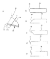
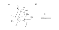
図8は、処理部32の他の形態を示す概略図である。図8(a)には図1(b)と同じ図を示しているが、このA−A断面の形状は、図8(b)〜(f)に示すような形状であってもよい。また処理部32の形状は、図9,10に示すような形状で構成されてもよい。
FIG. 8 is a schematic diagram showing another form of the
ここで、図8〜図10に示す形態についてそれぞれ説明する。 Here, each of the configurations shown in FIGS. 8 to 10 will be described.
図8(b)には、A−A断面で、処理面33における駆動軸11の軸方向の両端部に面取り(丸み面取り)が施された構成を示している。
FIG. 8B shows a configuration in which both ends of the
図8(c),(d)には、処理面33が駆動軸11に対して角度を持つように形成された構成を示している。
8C and 8D show a configuration in which the
図8(e)には、処理面33における駆動軸11の軸方向の中央部分が、回転体30の回転方向Rの下流側に凸となる湾曲形状をなしている構成を示している。
FIG. 8E shows a configuration in which a central portion of the
図8(f)には、処理面33における駆動軸11の軸方向の中央部分が、回転体30の回転方向Rの上流側に凹となる湾曲形状をなしている構成を示している。
FIG. 8F shows a configuration in which the central portion of the
図9(a)には、駆動軸11の軸方向から見たときに、処理面33が回転体30の回転方向Rの上流側に凹となる湾曲形状をなす構成を示している。図9(b)には、図9(a)に示す処理面33を回転体30の回転方向Rの下流側から見た図を示している。
FIG. 9A shows a configuration in which the
図9(c)には、駆動軸11の軸方向から見たときに、処理面33が回転体30の回転方向Rの下流側に凸となる湾曲形状をなす構成を示している。図9(d)には、図9(c)に示す処理面33を回転体30の回転方向Rの下流側から見た図を示している。
FIG. 9C shows a configuration in which the
図10には、駆動軸11の軸方向から見たときに、処理面33が、処理面33の第1部位33a、第2部位33bを結ぶ線aに沿った凹凸形状をなす構成を示している。
FIG. 10 shows a configuration in which the
次に、本発明に係る各物性の測定方法に関して記載する。 Next, a method for measuring each physical property according to the present invention will be described.
<有機無機複合微粒子の個数平均粒径の測定方法>
有機無機複合微粒子の一次粒子の個数平均粒径(D1)の測定は、走査型電子顕微鏡「S−4800」(商品名;日立製作所製)を用いて行う。有機無機複合微粒子、及び有機無機複合微粒子が外添されたトナーを観察して、最大20万倍に拡大した視野において、ランダムに100個の有機無機複合微粒子の一次粒子の長径を測定して個数平均粒径(D1)を求める。観察倍率は有機無機複合微粒子の大きさによって適宜調整する。
<Method of measuring number average particle size of organic-inorganic composite fine particles>
The number average particle diameter (D1) of the primary particles of the organic-inorganic composite fine particles is measured using a scanning electron microscope “S-4800” (trade name; manufactured by Hitachi, Ltd.). By observing the organic-inorganic composite particles and the toner to which the organic-inorganic composite particles are externally added, the major axis of 100 primary particles of the organic-inorganic composite particles is randomly measured in a field of view magnified up to 200,000 times. The average particle size (D1) is determined. The observation magnification is appropriately adjusted depending on the size of the organic-inorganic composite fine particles.
<有機無機複合微粒子の形状係数SF−2の測定方法>
有機無機複合微粒子の形状係数SF−2の測定は、走査型電子顕微鏡「S−4800」(商品名;日立製作所製)を用いて行う。有機無機複合微粒子が外添された磁性トナーを観察し以下のように算出した。
<Method of measuring shape factor SF-2 of organic-inorganic composite fine particles>
The shape factor SF-2 of the organic-inorganic composite fine particles is measured using a scanning electron microscope "S-4800" (trade name; manufactured by Hitachi, Ltd.). The magnetic toner to which the organic-inorganic composite fine particles were externally added was observed and calculated as follows.
観察倍率は有機無機複合微粒子の大きさによって適宜調整した。最大20万倍に拡大した視野において、画像処理ソフト「Image−Pro Plus5.1J」(MediaCybernetics社製)を使用し、ランダムに100個の有機無機複合微粒子の一次粒子の周囲長および面積を算出した。 The observation magnification was appropriately adjusted according to the size of the organic-inorganic composite fine particles. In a field of view magnified up to 200,000 times, the perimeter and area of 100 primary particles of organic-inorganic composite particles were randomly calculated using image processing software "Image-Pro Plus 5.1J" (manufactured by Media Cybernetics). ..
SF−2は下記の式にて算出し、その平均値をSF−2とした。
SF−2=(粒子の周囲長)2/粒子の面積×100/4π
SF-2 was calculated by the following formula, and the average value was defined as SF-2.
SF-2=(perimeter of particle) 2 /area of particle×100/4π
<有機無機複合微粒子の固着している粒子の割合および弱付着粒子の割合の測定方法>
まずトナーを「コンタミノンN」(非イオン界面活性剤、陰イオン界面活性剤、有機ビルダーからなるpH7の精密測定器洗浄用中性洗剤の10質量%水溶液、和光純薬工業社製)を数滴加えたイオン交換水に、AsOne社製UltraSonicCleanerVS−150を用いて超音波分散し、24時間静置する。この上澄み液を採取して乾燥することで、外添剤を単離することができる。トナーに複数の外添剤が外添されている場合は、上澄み液を、コクサン株式会社製H−9Rを用いて、25℃、5000rpmで1分間の条件で遠心分離することにより有機無機複合微粒子の単離が可能である。
<Measurement Method of Percentage of Sticking Particles of Organic-Inorganic Composite Fine Particles and Weakly Attached Particles>
First of all, the number of toner "Contaminon N" (a nonionic surfactant, anionic surfactant, 10% by weight aqueous solution of a neutral detergent for washing precision measuring instruments of
このようにして単離した有機無機複合微粒子を、再度コンタミノンNを数滴加えたイオン交換水に基準量分散し、標準溶液を作製する。 The organic-inorganic composite fine particles thus isolated are again dispersed in ion-exchanged water containing a few drops of Contaminone N in a standard amount to prepare a standard solution.
次に、コンタミノンNを数滴加えたイオン交換水にトナーを分散した後、超音波で10秒分散し、その後、遠心分離によりトナー粒子を沈降させる。再度超音波で20秒分散した後、遠心分離によりトナー粒子を沈降させる。再度超音波で60秒分散した後、遠心分離によりトナー粒子を沈降させる。この段階での上澄み液と、該標準溶液をそれぞれディスク遠心式粒度分布測定装置DC24000UHR(日本ルフト株式会社)による測定を行い、有機無機複合微粒子の粒径の位置に現れるピークの面積を比較し、有機無機複合微粒子の弱付着粒子の割合を定量する。 Next, the toner is dispersed in ion-exchanged water to which a few drops of Contaminone N have been added, followed by ultrasonic dispersion for 10 seconds, and then the toner particles are settled by centrifugation. After dispersing again by ultrasonic waves for 20 seconds, the toner particles are settled by centrifugation. After dispersing again by ultrasonic waves for 60 seconds, the toner particles are settled by centrifugation. The supernatant and the standard solution at this stage were respectively measured by a disk centrifugal particle size distribution analyzer DC24000UHR (Japan Luft Co., Ltd.) to compare the areas of peaks appearing at the particle size positions of the organic-inorganic composite fine particles, The proportion of weakly adhered particles of the organic-inorganic composite fine particles is quantified.
また有機無機複合微粒子の全添加部数は、コンタミノンNを数滴加えたイオン交換水10.0gにトナー1.0gを分散した後、超音波処理を3時間行い、その後、遠心分離によりトナー母粒子を沈降させる。この段階で上澄み液に存在する有機無機複合微粒子の存在量をディスク遠心式粒度分布測定により定量した値を有機無機複合微粒子の全添加部数とし、全添加部数から弱付着粒子の割合(質量部)を引いた値を有機無機複合微粒子の固着している粒子の割合(質量部)とする。 The total number of organic-inorganic composite fine particles added was 1.0 g of toner dispersed in 10.0 g of ion-exchanged water containing a few drops of Contaminone N, followed by ultrasonic treatment for 3 hours, and then centrifugation to separate toner mother particles. Let the particles settle. At this stage, the amount of the organic-inorganic composite fine particles present in the supernatant liquid was quantified by the disk centrifugal particle size distribution measurement, and the total addition number of the organic-inorganic composite fine particles was defined as the ratio of the weakly adhered particles (mass part) to the total addition number. The value obtained by subtracting is the ratio (parts by mass) of the particles to which the organic-inorganic composite fine particles are fixed.
尚、超音波処理は、以下の装置/条件で行う。
超音波式ホモジナイザーVP−050(タイテック株式会社製)
マイクロチップ:ステップ型マイクロチップ、先端径2mm
マイクロチップの先端位置:ガラスバイアルの中央部、且つバイアル底面から5mmの高さ
超音波条件:
強度30%
The ultrasonic treatment is performed under the following apparatus/conditions.
Ultrasonic homogenizer VP-050 (manufactured by Taitec Co., Ltd.)
Microchip: Step type microchip, tip diameter 2mm
Microchip tip position: central part of glass vial, and height of 5 mm from bottom of vial Ultrasonic conditions:
分散液が昇温しないようにバイアルを氷水で冷却しながら超音波を印加する。 Apply ultrasonic waves while cooling the vial with ice water so that the temperature of the dispersion does not rise.
<単位拡散指数の測定方法>
本発明における単位拡散指数は下記式で求められる。
単位拡散指数=Sr/Si
Sr:実測から求められる有機無機複合微粒子によるトナー粒子表面の被覆率
Si:有機無機複合微粒子が理想的に拡散した場合の有機無機複合微粒子によるトナー粒子表面の被覆率
<Measurement method of unit diffusion index>
The unit diffusion index in the present invention is calculated by the following formula.
Unit diffusion index=Sr/Si
Sr: Coverage of toner particle surface with organic-inorganic composite fine particles obtained from actual measurement Si: Coverage of toner particle surface with organic-inorganic composite fine particles when organic-inorganic composite fine particles are ideally diffused
Srは日立超高分解能電界放出形走査電子顕微鏡S−4800((株)日立ハイテクノロジーズ)にて撮影されたトナー表面画像を、画像解析ソフトImage−Pro Plus ver.5.0((株)日本ローパー)により解析して算出する。S−4800の画像撮影条件は以下の通りである。 Sr is a toner surface image photographed by Hitachi Ultra High Resolution Field Emission Scanning Electron Microscope S-4800 (Hitachi High Technologies Co., Ltd.), and image analysis software Image-Pro Plus ver. Calculated by analysis with 5.0 (Nippon Roper Co., Ltd.). The image capturing conditions of S-4800 are as follows.
(1)試料作製
試料台(アルミニウム試料台15mm×6mm)に導電性ペーストを薄く塗り、その上にトナーを吹きつける。さらにエアブローして、余分なトナーを試料台から除去し十分乾燥させる。試料台を試料ホルダにセットし、試料高さゲージにより試料台高さを36mmに調節する。
(1) Sample Preparation A sample table (aluminum sample table 15 mm×6 mm) is thinly coated with a conductive paste, and toner is sprayed on the conductive paste. Further, air blow is performed to remove excess toner from the sample table and dry it sufficiently. The sample stage is set on the sample holder, and the sample stage height is adjusted to 36 mm by the sample height gauge.
(2)S−4800観察条件設定
有機無機複合微粒子の被覆率の算出は、S−4800の反射電子像観察により得られた画像を用いて行う。反射電子像は2次電子像と比べてチャージアップが少ないため、有機無機複合微粒子の被覆率を精度良く測定することが出来る。
(2) S-4800 observation condition setting The coverage of the organic-inorganic composite fine particles is calculated using the image obtained by the backscattered electron image observation of S-4800. Since the backscattered electron image has less charge-up than the secondary electron image, the coverage of the organic-inorganic composite fine particles can be accurately measured.
S−4800の鏡体に取り付けられているアンチコンタミネーショントラップに液体窒素を溢れるまで注入し、30分間置く。S−4800の「PC−SEM」を起動し、フラッシング(電子源であるFEチップの清浄化)を行う。画面上のコントロールパネルの加速電圧表示部分をクリックし、[フラッシング]ボタンを押し、フラッシング実行ダイアログを開く。フラッシング強度が2であることを確認し実行する。フラッシングによるエミッション電流が20〜40μAであることを確認する。試料ホルダをS−4800鏡体の試料室に挿入する。コントロールパネル上の[原点]を押し試料ホルダを観察位置に移動させる。 Inject liquid nitrogen into the anti-contamination trap attached to the mirror body of S-4800 until it overflows, and leave it for 30 minutes. The "PC-SEM" of S-4800 is started and flushing (cleaning of the FE chip which is the electron source) is performed. Click the accelerating voltage display part of the control panel on the screen and press the [Flushing] button to open the flushing execution dialog. Execute after confirming that the flushing strength is 2. Confirm that the emission current due to flashing is 20 to 40 μA. Insert the sample holder into the sample chamber of the S-4800 body. Press [Origin] on the control panel and move the sample holder to the observation position.
加速電圧表示部をクリックしてHV設定ダイアログを開き、加速電圧を[0.8kV]、エミッション電流を[20μA]に設定する。オペレーションパネルの[基本]のタブ内にて、信号選択を[SE]に設置し、SE検出器を[上(U)]および[+BSE]を選択し、[+BSE]の右の選択ボックスで[L.A.100]を選択し、反射電子像で観察するモードにする。 Click the acceleration voltage display area to open the HV setting dialog, and set the acceleration voltage to [0.8 kV] and the emission current to [20 μA]. In the [Basic] tab of the operation panel, set the signal selection to [SE], select the SE detector [Up (U)] and [+BSE], and select [+BSE] in the selection box to the right. L. A. 100] is selected, and the mode is set to observe with a backscattered electron image.
同じくオペレーションパネルの[基本]のタブ内にて、電子光学系条件ブロックのプローブ電流を[Normal]に、焦点モードを[UHR]に、WDを[3.0mm]に設定する。コントロールパネルの加速電圧表示部の[ON]ボタンを押し、加速電圧を印加する。 Similarly, in the [Basic] tab of the operation panel, set the probe current of the electron optical system condition block to [Normal], the focus mode to [UHR], and the WD to [3.0 mm]. Press the [ON] button on the acceleration voltage display section of the control panel to apply the acceleration voltage.
(3)焦点調整
コントロールパネルの倍率表示部内をドラッグして、倍率を5000(5k)倍に設定する。操作パネルのフォーカスつまみ[COARSE]を回転させ、視野内全体にある程度焦点が合ったところでアパーチャアライメントの調整を行う。コントロールパネルの[Align]をクリックし、アライメントダイアログを表示し、[ビーム]を選択する。操作パネルのSTIGMA/ALIGNMENTつまみ(X,Y)を回転し、表示されるビームを同心円の中心に移動させる。次に[アパーチャ]を選択し、STIGMA/ALIGNMENTつまみ(X,Y)を一つずつ回し、像の動きを止める又は最小の動きになるように合わせる。アパーチャダイアログを閉じ、オートフォーカスで、ピントを合わせる。この操作を更に2度繰り返し、ピントを合わせる。
(3) Focus adjustment Drag inside the magnification display area of the control panel to set the magnification to 5000 (5k) times. The focus knob [COARSE] on the operation panel is rotated to adjust the aperture alignment when the entire field of view is in focus. Click [Align] on the control panel to display the alignment dialog and select [Beam]. The STIGMA/ALIGNMENT knobs (X, Y) on the operation panel are rotated to move the displayed beam to the center of the concentric circles. Next, select [Aperture] and turn the STIGMA/ALIGNMENT knobs (X, Y) one by one to stop the movement of the image or adjust the movement so as to minimize the movement. Close the aperture dialog and use auto focus to focus. Repeat this operation twice more to focus.
次に対象のトナーについて、最大径の中点を測定画面の中央に合わせた状態でコントロールパネルの倍率表示部内をドラッグして、倍率を10000(10k)倍に設定する。操作パネルのフォーカスつまみ[COARSE]を回転させ、ある程度焦点が合ったところでアパーチャアライメントの調整を行う。コントロールパネルの[Align]をクリックし、アライメントダイアログを表示し、[ビーム]を選択する。操作パネルのSTIGMA/ALIGNMENTつまみ(X,Y)を回転し、表示されるビームを同心円の中心に移動させる。次に[アパーチャ]を選択し、STIGMA/ALIGNMENTつまみ(X,Y)を一つずつ回し、像の動きを止める又は最小の動きになるように合わせる。アパーチャダイアログを閉じ、オートフォーカスで、ピントを合わせる。その後、倍率を50000(50k)倍に設定し、上記と同様にフォーカスつまみ、STIGMA/ALIGNMENTつまみを使用して焦点調整を行い、再度オートフォーカスでピントを合わせる。この操作を再度繰り返し、ピントを合わせる。ここで、観察面の傾斜角度が大きいと被覆率の測定精度が低くなりやすいので、ピント調整の際に観察面全体のピントが同時に合うものを選ぶことで、表面の傾斜が極力無いものを選択して解析する。 Next, for the target toner, the magnification is set to 10000 (10k) times by dragging in the magnification display portion of the control panel with the center of the maximum diameter aligned with the center of the measurement screen. Rotate the focus knob [COARSE] on the operation panel to adjust the aperture alignment when the focus is adjusted to some extent. Click [Align] on the control panel to display the alignment dialog and select [Beam]. The STIGMA/ALIGNMENT knobs (X, Y) on the operation panel are rotated to move the displayed beam to the center of the concentric circles. Next, select [Aperture] and turn the STIGMA/ALIGNMENT knobs (X, Y) one by one to stop the movement of the image or adjust the movement so as to minimize the movement. Close the aperture dialog and focus with auto focus. After that, the magnification is set to 50,000 (50k) times, focus adjustment is performed using the focus knob and STIGMA/ALIGNMENT knob in the same manner as above, and focus is adjusted again by autofocus. Repeat this operation again to focus. Here, if the inclination angle of the observation surface is large, the measurement accuracy of the coverage rate tends to be low, so by selecting the ones that are in focus on the entire observation surface at the same time when adjusting the focus, select the one with the smallest surface inclination. And analyze.
(4)画像保存
ABCモードで明るさ合わせを行い、サイズ640×480ピクセルで写真撮影して保存する。この画像ファイルを用いて下記の解析を行う。トナー粒子一つに対して写真を1枚撮影し、少なくともトナー30粒子以上について画像を得る。
(4) Image storage The brightness is adjusted in the ABC mode, and a picture is taken with a size of 640×480 pixels and saved. The following analysis is performed using this image file. One photograph is taken for each toner particle, and an image is obtained for at least 30 toner particles.
(5)画像解析
本発明では下記解析ソフトを用いて、上述した手法で得た画像を2値化処理することで有機無機複合微粒子の被覆率を算出する。このとき、上記一画面を正方形で12分割してそれぞれ解析する。
(5) Image Analysis In the present invention, the coverage of the organic-inorganic composite fine particles is calculated by binarizing the image obtained by the method described above using the following analysis software. At this time, the above-mentioned one screen is divided into 12 squares and analyzed.
被覆率の計算は、正方形の領域を囲って解析を行う。この時、領域の面積(C)は24000〜26000ピクセルになるようにする。 The calculation of the coverage is performed by surrounding a square area. At this time, the area (C) of the area is set to 24000 to 26000 pixels.
ここで有機無機複合微粒子の輪郭の領域指定を行い、有機無機複合微粒子の被覆面積(D)を算出する。 Here, the contour area of the organic-inorganic composite fine particles is designated, and the covered area (D) of the organic-inorganic composite fine particles is calculated.
正方形の領域の面積C、有機無機複合微粒子の被覆面積Dから下記式で被覆率Srが求められる。
Sr(%)=D/C×100
From the area C of the square region and the coating area D of the organic-inorganic composite fine particles, the coverage Sr can be calculated by the following formula.
Sr(%)=D/C×100
有機無機複合微粒子の被覆率の計算はトナー30粒子以上について行う。得られた全データの平均値を本発明におけるSrとする。 The calculation of the coverage of the organic-inorganic composite fine particles is performed for 30 or more toner particles. The average value of all the obtained data is Sr in the present invention.
Siの求め方は次の通りである。 The method of obtaining Si is as follows.
まず有機無機複合微粒子のトナー1gあたりの含有質量(Ay)[g]と密度(Gy)[g/m3]、粒径(Dy)[m]から有機無機複合微粒子のトナー1gあたりの含有個数(N)を計算する。Ayは先述の通りディスク遠心式粒度分布測定装置で測定した。Gyは島津製作所製の乾式自動密度計アキュピック1330で測定した。Dyは先述の通り走査型電子顕微鏡S−4800で測定した。Nの計算式を以下に示す。
N=Ay/(4/3・π・(Dy/2)3・Gy)
First, based on the content (Ay) [g], the density (Gy) [g/m 3 ] and the particle size (Dy) [m] of the organic-inorganic composite fine particles per 1 g of the toner, the number of the organic-inorganic composite fine particles contained per 1 g of the toner is determined. Calculate (N). Ay was measured by a disc centrifugal type particle size distribution measuring device as described above. Gy was measured with a dry automatic densimeter Accupic 1330 manufactured by Shimadzu Corporation. Dy was measured with the scanning electron microscope S-4800 as described above. The calculation formula of N is shown below.
N=Ay/(4/3・π・(Dy/2) 3・Gy)
次にSr測定時と同様に撮影した電子顕微鏡画像のうち、凝集せず単分散している有機無機複合微粒子を30個以上選択し、そのうち面積が小さい方から10個の平均値を求め、算出した平均値を有機無機複合微粒子の1個当たりの被覆面積(S1)[m2]とする。 Next, from the electron microscope images taken in the same manner as in the Sr measurement, 30 or more mono-dispersed organic-inorganic composite fine particles without aggregation were selected, and the average value of 10 from the smaller area was calculated and calculated. The averaged value is defined as the coating area (S1) [m 2 ] per organic-inorganic composite fine particle.
また外添剤を全て遊離させたトナー粒子の1gあたりの表面積(Sm)[m2]を定容法によるガス吸着法を測定方式として採用している「自動比表面積・細孔分布測定装置 TriStar3000(島津製作所社製)」を用いて計測する。 In addition, the automatic surface area/pore distribution measuring device TriStar 3000 that employs the gas adsorption method based on the constant volume method as the measuring method is the surface area (Sm) [m 2 ] per 1 g of the toner particles in which all the external additives are released. (Made by Shimadzu Corporation)”.
これらの値を下記式に代入しSiを求める。
Si(%)=N×S1/Sm×100
Substituting these values into the following formula, Si is calculated.
Si(%)=N×S1/Sm×100
<無機微粒子aのBET比表面積の測定方法>
無機微粒子aのBET比表面積の測定は、JIS Z8830(2001年)に準じる。
<Method for measuring BET specific surface area of inorganic fine particles a>
The BET specific surface area of the inorganic fine particles a is measured according to JIS Z8830 (2001).
測定装置としては、定容法によるガス吸着法を測定方式として採用している「自動比表面積・細孔分布測定装置 TriStar3000(島津製作所社製)」を用いる。測定条件の設定及び測定データの解析は、本装置に付属の専用ソフト「TriStar3000 Version4.00」を用いて行う。また装置には真空ポンプ、窒素ガス配管、ヘリウムガス配管が接続される。窒素ガスを吸着ガスとして用い、BET多点法により算出した値を本発明におけるBET比表面積とする。 As the measuring device, an “automatic specific surface area/pore distribution measuring device TriStar 3000 (manufactured by Shimadzu Corporation)” that employs a gas adsorption method by a constant volume method as a measuring method is used. The setting of the measurement conditions and the analysis of the measurement data are performed using the dedicated software "TriStar 3000 Version 4.00" attached to this device. A vacuum pump, a nitrogen gas pipe, and a helium gas pipe are connected to the device. The value calculated by the BET multipoint method using nitrogen gas as the adsorption gas is the BET specific surface area in the present invention.
以下に実施例及び比較例を挙げて本発明を更に詳細に説明するが、本発明は何らこれに制約されるものではない。なお、実施例及び比較例の部数は特に断りが無い場合、すべて質量基準である。 Hereinafter, the present invention will be described in more detail with reference to Examples and Comparative Examples, but the present invention is not limited thereto. In the examples and comparative examples, all parts are based on mass unless otherwise specified.
<ポリエステル樹脂1の製造例>
・ビスフェールAエチレンオキサイド付加物(2.2mol付加) 100.0部
・テレフタル酸 60.0部
・無水トリメリット酸 20.0部
・アクリル酸 10.0部
上記ポリエステルモノマーを4口フラスコに仕込み、減圧装置、水分離装置、窒素ガス導入装置、温度測定装置及び撹拌装置を装着して窒素雰囲気下にて160℃で撹拌した。反応終了後容器から取り出し、冷却、粉砕してポリエステル樹脂1を得た。ポリエステル樹脂1のTgは90.3℃、軟化点は135.5℃であった。
<Production Example of Polyester Resin 1>
-Bisfer A ethylene oxide adduct (2.2 mol addition) 100.0 parts-terephthalic acid 60.0 parts-trimellitic anhydride 20.0 parts-acrylic acid 10.0 parts The above polyester monomer was charged into a 4-neck flask. A pressure reducing device, a water separator, a nitrogen gas introducing device, a temperature measuring device and a stirring device were attached, and the mixture was stirred at 160° C. under a nitrogen atmosphere. After completion of the reaction, the product was taken out from the container, cooled and pulverized to obtain polyester resin 1. Polyester resin 1 had a Tg of 90.3°C and a softening point of 135.5°C.
<ポリエステル樹脂2の製造例>
・ビスフェールAプロピレンオキサイド付加物(2.2mol付加) 60.0部
・ビスフェールAエチレンオキサイド付加物(2.2mol付加) 40.0部
・テレフタル酸 77.0部
上記ポリエステルモノマー混合物をモノマー総量に対して、0.2質量%のジブチル錫オキシドとともに5リットルオートクレーブに仕込み、還流冷却器、水分分離装置、N2ガス導入管,温度計及び撹拌装置を付し、オートクレーブ内にN2ガスを導入しながら230℃で重縮合反応を行った。所望の軟化点になるように反応時間を調整し、反応終了後容器から取り出し、冷却、粉砕してポリエステル樹脂2を得た。ポリエステル樹脂2のTgは58.5℃、軟化点は90℃であった。
<Production Example of
・Bisfer A propylene oxide adduct (2.2 mol addition) 60.0 parts ・Bisfer A ethylene oxide adduct (2.2 mol addition) 40.0 parts ・Terephthalic acid 77.0 parts relative, were charged to a 5 liter autoclave together with 0.2 wt% of dibutyl tin oxide, reflux condenser, water separator, N2 gas inlet, denoted by the thermometer and a stirrer, N 2 gas is introduced into an autoclave While carrying out the polycondensation reaction at 230°C. The reaction time was adjusted so that the desired softening point was reached, and after completion of the reaction, the product was taken out from the container, cooled and pulverized to obtain
<トナー粒子1の製造例>
・ポリエステル樹脂1 60.0部
・ポリエステル樹脂2 40.0部
・球状磁性酸化鉄粒子(個数平均粒径=0.20μm、Hc=11.5kA/m、σs=88Am2/kg、σr=14Am2/kg) 60.0部
・離型剤(フィッシャートロプッシュワックス(サゾール社製、C105、融点105℃)) 2.0部
・荷電制御剤(T−77:保土ヶ谷化学社製) 2.0部
上記材料をヘンシェルミキサーで前混合した後、二軸混練押し出し機によって、溶融混練した。
<Production Example of Toner Particle 1>
-Polyester resin 1 60.0 parts-
得られた混練物を冷却し、ハンマーミルで粗粉砕した後、機械式粉砕機(ターボ工業(株)製T−250)で粉砕した。得られた微粉砕粉末をコアンダ効果を利用した多分割分級機を用いて分級し、重量平均粒径(D4)7.0μmの負帯電性の原料トナー粒子を得た。 The obtained kneaded product was cooled, roughly crushed with a hammer mill, and then crushed with a mechanical crusher (T-250 manufactured by Turbo Kogyo Co., Ltd.). The resulting finely pulverized powder was classified using a multi-division classifier utilizing the Coanda effect to obtain negatively chargeable raw material toner particles having a weight average particle diameter (D4) of 7.0 μm.
その原料トナー粒子を、表面改質装置ファカルティー(ホソカワミクロン社製)で表面改質処理を行った。その際、分散ローターの回転周速を150m/secとし、微粉砕品の投入量を1サイクル当たり7.6kgとし、表面改質時間(=サイクルタイム、原料供給が終了してから排出弁が開くまでの時間)を82secとした。またトナー母粒子排出時の温度は44℃であった。以上の工程を経てトナー母粒子1を得た。 The raw material toner particles were subjected to a surface modification treatment by a surface modification apparatus faculty (manufactured by Hosokawa Micron Co., Ltd.). At that time, the rotation peripheral speed of the dispersion rotor was set to 150 m/sec, the amount of finely pulverized product was set to 7.6 kg per cycle, and the surface modification time (=cycle time, the discharge valve was opened after the raw material supply was completed). Until) was set to 82 sec. The temperature at the time of discharging the toner mother particles was 44°C. Toner base particles 1 were obtained through the above steps.
<有機無機複合微粒子1乃至5の製造例>
有機無機複合微粒子は、WO2013/063291の実施例の記載に従って製造することができる。
<Production Example of Organic-Inorganic Composite Fine Particles 1 to 5>
The organic-inorganic composite fine particles can be produced according to the description of the example of WO2013/063291.
後述の実施例において用いる有機無機複合微粒子としては、表1に示すシリカを用いて、WO 2013/063291の実施例1に従って製造したものを用意した。有機無機複合微粒子1乃至5の物性を表1に示す。 As the organic-inorganic composite fine particles used in the examples described later, those prepared by using silica shown in Table 1 according to Example 1 of WO 2013/063291 were prepared. Table 1 shows the physical properties of the organic-inorganic composite fine particles 1 to 5.
有機無機複合微粒子1乃至5は、示差走査熱量分析(DSC)の測定において、20℃から220℃までの範囲に発熱ピーク、吸熱ピーク、ガラス転移点(Tg)は有さなかった。 The organic-inorganic composite fine particles 1 to 5 had no exothermic peak, endothermic peak, or glass transition point (Tg) in the range of 20° C. to 220° C. in the measurement by differential scanning calorimetry (DSC).
<有機無機複合微粒子6の製造例>
個数平均粒径100nmの樹脂粒子100部に対し個数平均粒径25nmのコロイダルシリカ4部をヘンシェルミキサーで混合し有機無機複合微粒子6を得た。有機無機複合微粒子6の物性を表1に示す。
<Production Example of Organic-Inorganic
Organic-inorganic composite
<有機無機複合微粒子7の製造例>
有機無機複合微粒子7は、特許第4321272号の実施例の記載に従って製造することができる。後述の実施例において用いる有機無機複合微粒子としては、表1に示すシリカを用いて、特許第4321272号の複合樹脂粒子の作製例に従って製造したものを用意した。有機無機複合微粒子7の物性を表1に示す。
<Production Example of Organic-Inorganic
The organic-inorganic composite
なお、用意した有機無機複合微粒子は、樹脂粒子の表面に無機微粒子Bに由来する凸部が存在する構造を有する粒子であった。 In addition, the prepared organic-inorganic composite fine particles were particles having a structure in which convex portions derived from the inorganic fine particles B were present on the surface of the resin particles.
<その他の添加剤>
後述のトナー製造例中で、上記有機無機複合微粒子以外に使用する添加剤として、コロイダルシリカの無機微粒子1を使用した。無機微粒子1の個数平均粒径は100nm、SF2は100であった。
<Other additives>
In the toner production examples described later, colloidal silica inorganic fine particles 1 were used as an additive other than the organic-inorganic composite fine particles. The inorganic fine particles 1 had a number average particle diameter of 100 nm and SF2 of 100.
<無機微粒子a1乃至a5>
無機微粒子aとしてヘキサメチルジシラザンで表面処理された疎水性シリカ微粉体を使用した。これらのBET比表面積を表2に示す。
<Inorganic fine particles a1 to a5>
As the inorganic fine particles a, a hydrophobic silica fine powder surface-treated with hexamethyldisilazane was used. Table 2 shows these BET specific surface areas.
<トナー処理装置1>
トナー処理装置の具体的な構成について、図2を用いて詳細に説明する。
<Toner processor 1>
A specific configuration of the toner processing device will be described in detail with reference to FIG.
処理室10は、図2に示すような内寸高さが250mm、内径がφ230mmで有効容量が10Lの円筒形状の容器で平らな底部の中心に駆動軸11を備えている。駆動モータ50の駆動は駆動ベルトを介して駆動軸11に伝達されている。制御部60は、電源スイッチ、駆動ONスイッチ、駆動停止スイッチ、回転数調整ボリューム、回転数表示部、品温表示部等を備え、トナー処理装置の動作を制御する。
The
上述の様に、処理室10内部には、被処理物を処理室10の底部から上方に舞上げる図4に示す撹拌羽根20が駆動軸11に取り付けられている。撹拌羽根20はS字形状で先端が跳ねあげ形状のものが使用されている。さらに撹拌羽根20の上方には、同じ駆動軸11に、図5示す回転体30が取り付けられている。
As described above, inside the
回転体30には、円環状の回転体本体31の外周面31aから外径方向に突き出した処理部32が2か所設けられている。
The rotating
処理面33は、図6(b)に示すように角度θ=100度である。また処理面33のうち回転体本体31に最も近い第1部位が内周面10aの半径の65%の位置であり、また処理面33のうち回転体本体31から最も離れた端部位置が内周面10aの半径の95%の位置である。
The
上記構成のトナー処理装置をトナー処理装置1とする。 The toner processing device having the above configuration is referred to as a toner processing device 1.
<トナー処理装置2乃至8>
トナー処理装置1の処理面33の角度θ、処理面33のうち回転体本体31に最も近い第1部位までの駆動軸11からの長さの内周面10aの半径に対する比率、及び処理面33のうち回転体本体31から最も離れた端部までの駆動軸11からの長さの内周面10aの半径に対する比率を、表3の様に変更した以外は同様の処理装置2乃至8を用意した。
<
The angle θ of the
<トナー処理装置9>
処理面33の構成はトナー処理装置1と同様にし、駆動軸11を中心として対向している2個の処理部32に加えて、更に2個の処理部を回転体本体の外径上の既存の二つの処理部の中間点に増設し、合計4個の処理部を有する処理装置9を用意した。
<Toner processor 9>
The structure of the
<トナー1の製造例>
[第一混合工程]
トナー粒子1 100.0部に対し、有機無機複合微粒子1を1.0部添加し、トナー処理装置1を用いて、3200rpmで8分間混合した。
<Production Example of Toner 1>
[First mixing step]
1.0 part of the organic-inorganic composite fine particles 1 was added to 100.0 parts of the toner particles 1, and the mixture was mixed for 8 minutes at 3200 rpm using the toner processing apparatus 1.
[第二混合工程]
第一混合工程において得られた混合物に対して、無機微粒子a1を0.8部添加し、トナー処理装置1を用いて、3200rpmで1分間混合し、トナー1を得た。トナー1の物性を表4に示す。
[Second mixing step]
To the mixture obtained in the first mixing step, 0.8 part of the inorganic fine particles a1 was added, and the mixture was mixed for 1 minute at 3200 rpm using the toner processing device 1 to obtain a toner 1. Table 4 shows the physical properties of Toner 1.
なおトナー1から分析した有機無機複合微粒子1の個数平均粒径(D1)、形状係数SF−2は表1に示す値と同等であった。 The number average particle diameter (D1) and the shape factor SF-2 of the organic-inorganic composite fine particles 1 analyzed from the toner 1 were equivalent to the values shown in Table 1.
<トナー2乃至20の製造例>
有機無機複合微粒子、無機微粒子a、及びトナー処理装置の種類を表5の様に変更した以外はトナー1と同様にして、トナー2乃至20を得た。得られたトナー2乃至20の物性を表4に示す。
<Production Example of
但し、トナー2の製造においては、第一混合工程で、無機微粒子aの内0.3質量部を有機無機複合微粒子と同時に添加し、第2混合工程で、無機微粒子aの残り0.7質量部を添加した。
However, in the production of the
さらに、トナー14、15、及び20の製造においては、第一混合工程で、無機微粒子aの全量を有機無機複合微粒子と同時に投入し、第二混合工程は行わなかった。なおトナー2乃至20から分析した有機無機複合微粒子1乃至7の個数平均粒径(D1)、形状係数SF−2は表1に示す値と同等であった。
Further, in the production of the
〔実施例1乃至13、比較例1乃至7〕
<トナーの耐久性能の評価>
評価機としてHP LaserJet EnterpriseM806dnと所定のカートリッジ(HP社製)を改造して使用した。
[Examples 1 to 13, Comparative Examples 1 to 7]
<Evaluation of toner durability performance>
As an evaluation machine, HP LaserJet Enterprise M806dn and a predetermined cartridge (manufactured by HP) were modified and used.
HP LaserJet EnterpriseM806dn本体を、本来のプロセススピードよりも高速である400mm/sに改造した。カートリッジはトナーを製品充填量より多い1800gを投入した。これに伴いトナーの循環を改善するために撹拌翼を大型化した。 The HP LaserJet Enterprise M806dn main body was modified to 400 mm/s, which is faster than the original process speed. The cartridge was loaded with 1800 g of toner, which is larger than the product filling amount. Along with this, the stirring blade was enlarged to improve the toner circulation.
上記本体とカートリッジを印字率5%となる横線パターンを2枚/1ジョブとして、ジョブとジョブの間にマシンがいったん停止してから次のジョブが始まるように設定したモードで600000枚の画像出力試験を実施した。100枚目と600000枚目での画像濃度を測定し、同時に現像スリーブ上での遊離外添剤に起因する融着の発生状況を確認した。評価はトナーの帯電特性を低下させ画像出力により厳しい条件である高温高湿環境下(32.5℃,85%RH)で行った。 Outputting 600,000 sheets of images in a mode where the main body and the cartridge have a horizontal line pattern with a printing rate of 5% as 2 sheets/1 job, and the machine is stopped between jobs before the next job starts. The test was conducted. The image densities on the 100th and 600,000th sheets were measured, and at the same time, the occurrence of fusion due to the free external additive on the developing sleeve was confirmed. The evaluation was carried out under a high temperature and high humidity environment (32.5° C., 85% RH), which is a severe condition for image output by deteriorating the charging property of the toner.
画像濃度は、反射濃度計であるマクベス濃度計(マクベス社製)でSPIフィルターを使用して、5mm丸のベタ黒画像の反射濃度を測定することにより測定した。数値が大きいほど現像性が良いことを示す。具体的な評価基準を以下に示す。
A:1.45以上
B:1.40以上1.45未満
C:1.35以上1.40未満
D:1.35未満
The image density was measured by measuring the reflection density of a solid black image of a circle of 5 mm with a Macbeth densitometer (manufactured by Macbeth Co.) which is a reflection densitometer. The larger the value, the better the developability. The specific evaluation criteria are shown below.
A: 1.45 or more B: 1.40 or more and less than 1.45 C: 1.35 or more and less than 1.40 D: less than 1.35
<現像スリーブ汚染の評価>
前記耐久性能の評価中、画像評価試験を行うのと同時に、現像スリーブ上での遊離外添剤に起因する融着の発生状況を目視で評価した。評価基準を以下に示す。
A:汚染無し
B:縦筋が1本以上4本以下発生
C:縦筋が5本以上発生しているが、画像弊害は未発生
D:縦筋が5本以上発生し、且つ現像スリーブ上のトナー被覆が不均一化し画像弊害が発生
<Evaluation of development sleeve contamination>
While performing the image evaluation test during the evaluation of the durability performance, the occurrence of fusion due to the free external additive on the developing sleeve was visually evaluated. The evaluation criteria are shown below.
A: No pollution B: Vertical streaks 1 to 4 or less C: Vertical streaks 5 or more, but no image adverse effect D: Vertical streaks 5 or more and on developing sleeve Toner coating becomes non-uniform and image damage occurs
評価を行った結果を表6に示す。 The results of the evaluation are shown in Table 6.
Claims (2)
有機無機複合微粒子と、
無機微粒子aと
を有するトナーであって、
該有機無機複合微粒子は、
(1)樹脂粒子と無機微粒子bとを有し、該樹脂粒子の表面に該無機微粒子bに由来する凸部が存在する構造を有する粒子であり、
(2)個数平均粒径(D1)が50nm以上500nm以下であり、
(3)倍率20万倍に拡大して測定される形状係数SF−2が103以上120以下であり、
(4)該トナー粒子に対して固着している該有機無機複合微粒子の量Y(質量部)が、該トナー粒子100質量部に対して0.45質量部以上3.00質量部以下であり、該トナー粒子に対して固着している該有機無機複合微粒子の量Y(質量部)は、以下の測定方法で求められるものであり、
該トナー粒子100質量部に対する該有機無機複合微粒子の量をX(質量部)としたとき、該Xと該Yとが、
X−Y≦0.30
を満たし、
下式で算出される、トナー粒子表面における該有機無機複合微粒子の単位拡散指数が0.75以上であり、該単位拡散指数は、以下の測定方法で求められるものであり、該無機微粒子aは、BET比表面積が50m2/g以上400m2/g以下である、
ことを特徴とするトナー。
・トナー粒子に対して固着している有機無機複合微粒子の量Y(質量部)の測定方法
非イオン界面活性剤、陰イオン界面活性剤及び有機ビルダーからなるpH7の中性洗剤の10質量%水溶液を数滴加えたイオン交換水にトナーをウルトラソニッククリーナーを用いて超音波分散し、24時間静置する。この上澄み液を採取して乾燥し、外添剤を単離する。トナーには複数の外添剤が外添されているため、25℃及び5000rpmで1分間の条件で上澄み液を遠心分離し、有機無機複合微粒子を単離する。
単離した有機無機複合微粒子を、再度上記10質量%水溶液を数滴加えたイオン交換水に基準量分散し、有機無機複合微粒子の濃度が既知の標準溶液を作製する。
次に、上記10質量%水溶液を数滴加えたイオン交換水にトナーを分散し、トナーの濃度が既知の第一のトナー分散液を作製した後、ウルトラソニッククリーナーを用いて超音波で10秒分散し、その後、遠心分離によりトナー粒子を沈降させる。再度ウルトラソニッククリーナーを用いて超音波で20秒分散した後、遠心分離によりトナー粒子を沈降させる。再度ウルトラソニッククリーナーを用いて超音波で60秒分散し、トナー粒子に対して固着していない弱付着の有機無機複合微粒子をトナー粒子から離した後、遠心分離によりトナー粒子を沈降させる。この段階での第一の上澄み液及び標準溶液に対してそれぞれディスク遠心式粒度分布測定装置による測定を行い、両液の有機無機複合微粒子の粒径の位置に現れるピークの面積を比較し、第一の上澄み液における弱付着の有機無機複合微粒子の濃度を求める。第一の上澄み液における弱付着の有機無機複合微粒子の濃度から、第一のトナー分散液における弱付着の有機無機複合微粒子の濃度を求める。第一のトナー分散液における弱付着の有機無機複合微粒子及び第一のトナー分散液におけるトナーの濃度から、トナーに含まれる弱付着の有機無機複合微粒子の量(トナー100質量部に対する量(質量部))を求める。
また、上記10質量%水溶液を数滴加えたイオン交換水10.0gにトナー1.0gを分散し、トナーの濃度が既知の第二のトナー分散液を作製した後、超音波ホモジナイザーを用いて超音波処理を3時間行い、全部の有機無機複合微粒子(トナー粒子に対して固着している有機無機複合微粒子及び固着していない弱付着の有機無機複合微粒子)をトナー粒子から離した後、遠心分離によりトナー粒子を沈降させる。この段階で第二の上澄み液及び標準溶液に対してそれぞれディスク遠心式粒度分布測定による測定を行い、両液の有機無機複合微粒子の粒径の位置に現れるピークの面積を比較し、第二の上澄み液における有機無機複合微粒子の濃度を求める。第二のトナー分散液における有機無機複合微粒子及び第二のトナー分散液におけるトナーの濃度から、トナーに含まれる有機無機複合微粒子の全量(トナー100質量部に対する量(質量部):全添加部数)を求める。
トナーに含まれる有機無機複合微粒子の全量(質量部)からトナーに含まれる弱付着の有機無機複合微粒子の量(質量部)を引いた値を、トナーに含まれるトナー粒子に対して固着している有機無機複合微粒子の量Y(質量部)とする。
・単位拡散指数の測定方法
単位拡散指数は、単位拡散指数=Sr/Siで算出する。Srは、実測から求められる有機無機複合微粒子によるトナー粒子表面の被覆率であり、Siは、有機無機複合微粒子が理想的に拡散した場合の有機無機複合微粒子によるトナー粒子表面の被覆率である。Srは、走査型電子顕微鏡にて撮影されたトナー表面画像を、画像解析ソフトにより、次の通り解析して算出する。まず、上記トナー表面画像を2値化処理し、上記トナー表面画像を正方形で12分割してそれぞれ解析する。このとき、領域の面積(C)は24000〜26000ピクセルになるようにする。ここで有機無機複合微粒子の輪郭の領域指定を行い、有機無機複合微粒子の被覆面積(D)を算出する。正方形の領域の面積C、有機無機複合微粒子の被覆面積Dから、Sr(%)=D/C×100で被覆率Srが求められる。有機無機複合微粒子の被覆率の計算はトナー30粒子以上について行う。得られた全データの平均値を本発明におけるSrとする。
Siは、次の通り算出する。まず、有機無機複合微粒子のトナー1gあたりの含有質量(Ay)[g]と密度(Gy)[g/m3]、粒径(Dy)[m]から有機無機複合微粒子のトナー1gあたりの含有個数(N)を計算する。Ayはディスク遠心式粒度分布測定装置で測定する。Gyは乾式自動密度計で測定する。Dyは走査型電子顕微鏡で測定する。Nは、N=Ay/(4/3・π・(Dy/2)3・Gy)で算出する。次に、Sr測定時と同様に撮影した走査型電子顕微鏡の画像のうち、凝集せず単分散している有機無機複合微粒子を30個以上選択し、そのうち面積が小さい方から10個の平均値を求め、算出した平均値を有機無機複合微粒子の1個当たりの被覆面積(S1)[m2]とする。また、外添剤を全て遊離させたトナー粒子の1gあたりの表面積(Sm)[m2]を定容法によるガス吸着法を測定方式として採用している自動比表面積・細孔分布測定装置を用いて計測する。Siは、Si(%)=N×S1/Sm×100で算出する。 Toner particles containing a binder resin, a colorant and a release agent,
Organic-inorganic composite fine particles,
A toner having inorganic fine particles a,
The organic-inorganic composite fine particles,
(1) A particle having resin particles and inorganic fine particles b, and having a structure in which convex portions derived from the inorganic fine particles b are present on the surface of the resin particles,
(2) The number average particle diameter (D1) is 50 nm or more and 500 nm or less,
(3) The shape factor SF-2 measured at a magnification of 200,000 times is 103 or more and 120 or less,
(4) The amount Y (parts by mass) of the organic-inorganic composite fine particles fixed to the toner particles is 0.45 parts by mass or more and 3.00 parts by mass or less based on 100 parts by mass of the toner particles. The amount Y (parts by mass) of the organic-inorganic composite fine particles fixed to the toner particles is determined by the following measuring method,
When the amount of the organic inorganic composite fine particles to the toner particles 100 parts by weight and X (parts by weight), and the said X and said Y,
XY≦0.30
The filling,
The unit diffusion index of the organic-inorganic composite fine particles on the toner particle surface calculated by the following formula is 0.75 or more, and the unit diffusion index is calculated by the following measuring method. , The BET specific surface area is 50 m 2 /g or more and 400 m 2 /g or less,
Toner characterized by the above.
Method for measuring the amount Y (parts by mass) of the organic-inorganic composite fine particles adhered to the toner particles 10% by weight aqueous solution of a neutral detergent of pH 7 consisting of a nonionic surfactant, anionic surfactant and organic builder The toner is ultrasonically dispersed in ion-exchanged water to which a few drops of is added using an Ultrasonic cleaner, and the mixture is left standing for 24 hours. The supernatant is collected and dried to isolate the external additive. Since a plurality of external additives are externally added to the toner, the supernatant liquid is centrifuged at 25° C. and 5000 rpm for 1 minute to isolate the organic-inorganic composite fine particles.
The isolated organic-inorganic composite fine particles are dispersed again in a standard amount in ion-exchanged water to which a few drops of the above 10 mass% aqueous solution are added to prepare a standard solution having a known concentration of the organic-inorganic composite fine particles .
Next, the toner is dispersed in ion-exchanged water to which a few drops of the 10% by mass aqueous solution are added to prepare a first toner dispersion liquid having a known toner concentration , and then ultrasonic waves are applied for 10 seconds using an ultrasonic cleaner. Disperse and then sediment the toner particles by centrifugation. The toner particles are again dispersed by ultrasonic waves for 20 seconds using an Ultrasonic cleaner, and then the toner particles are settled by centrifugation. The particles are again dispersed by ultrasonic waves for 60 seconds using an Ultrasonic cleaner to separate the weakly adhering organic-inorganic composite fine particles not fixed to the toner particles from the toner particles, and then the toner particles are settled by centrifugation. At this stage, the first supernatant and the standard solution were respectively measured by a disk centrifugal type particle size distribution measuring device, and the areas of the peaks appearing at the particle size positions of the organic-inorganic composite fine particles of both solutions were compared . The concentration of weakly adhering organic-inorganic composite fine particles in one supernatant is obtained. From the concentration of the weakly adhered organic-inorganic composite fine particles in the first supernatant liquid, the concentration of the weakly adhered organic-inorganic composite fine particles in the first toner dispersion liquid is determined. From the concentration of the weakly adhering organic-inorganic composite fine particles in the first toner dispersion and the concentration of the toner in the first toner dispersion, the amount of the weakly adhering organic-inorganic composite fine particles contained in the toner (amount per 100 parts by mass of toner (parts by mass) )) Ru determined.
Further , 1.0 g of the toner is dispersed in 10.0 g of ion-exchanged water to which a few drops of the 10 mass% aqueous solution are added to prepare a second toner dispersion liquid having a known toner concentration , and then an ultrasonic homogenizer is used. Ultrasonic wave treatment for 3 hours to separate all the organic-inorganic composite fine particles (organic-inorganic composite fine particles fixed to the toner particles and weakly adhered organic-inorganic composite fine particles not fixed to the toner particles) from the toner particles , The toner particles are settled by centrifugation. Each was measured that by the disc centrifuge particle size distribution measured at this stage for the second supernatant and the standard solution, comparing the area of the peak appearing at the position of the particle size of the organic-inorganic composite particles of the two solutions, the The concentration of organic-inorganic composite fine particles in the second supernatant is obtained. From the concentration of the organic-inorganic composite fine particles in the second toner dispersion liquid and the toner concentration in the second toner dispersion liquid, the total amount of the organic-inorganic composite fine particles contained in the toner (amount per 100 parts by mass of toner (parts by mass): total number of addition parts ) the Ru asked.
Fixing all amounts minus the amount of the organic-inorganic composite fine particles of weak adhesion (parts by mass) contained from (parts by weight) in the toner of the organic-inorganic composite particles contained in the toner, the toner particles contained in the toner and the amount of the organic-inorganic composite fine particles Y (parts by weight) are.
-Measurement method of unit diffusion index The unit diffusion index is calculated by unit diffusion index=Sr/Si. Sr is the coverage of the toner particle surface with the organic-inorganic composite fine particles, which is obtained from actual measurement, and Si is the coverage of the toner particle surface with the organic-inorganic composite fine particles when the organic-inorganic composite fine particles are ideally diffused. Sr is calculated by analyzing the toner surface image photographed by the scanning electron microscope with the image analysis software as follows. First, the toner surface image is binarized, and the toner surface image is divided into 12 squares and analyzed. At this time, the area (C) of the area is set to 24000 to 26000 pixels. Here, the contour area of the organic-inorganic composite fine particles is designated, and the covered area (D) of the organic-inorganic composite fine particles is calculated. From the area C of the square region and the coating area D of the organic-inorganic composite fine particles, the coverage Sr is calculated by Sr(%)=D/C×100. The calculation of the coverage of the organic-inorganic composite fine particles is performed for 30 or more toner particles. The average value of all the obtained data is Sr in the present invention.
Si is calculated as follows. First, from the content (Ay) [g] and the density (Gy) [g/m 3 ] and the particle size (Dy) [m] of the organic-inorganic composite fine particles per 1 g of the toner, the content of the organic-inorganic composite fine particles per 1 g of the toner is described. Calculate the number (N). Ay is measured by a disc centrifugal type particle size distribution measuring device. Gy is measured by a dry type automatic densimeter. Dy is measured with a scanning electron microscope. N is calculated by N=Ay/(4/ 3 ·π·(Dy/2) 3 ·Gy). Next, from the images of the scanning electron microscope taken in the same manner as in the Sr measurement, 30 or more organic-inorganic composite fine particles that were not aggregated and were monodispersed were selected, and the average value of 10 from the smaller area was selected. And the calculated average value is defined as the coating area (S1) [m 2 ] per organic-inorganic composite fine particle. In addition, an automatic specific surface area/pore distribution measuring device adopting a gas adsorption method based on a constant volume method as a measuring method for the surface area (Sm) [m 2 ] per 1 g of toner particles in which all the external additives are released. Use to measure. Si is calculated by Si(%)=N×S1/Sm×100.
(1)処理室内に回転体を具備する処理装置を用いて該トナー粒子と該有機無機複合微粒子とを混合し、混合物を得る第一混合工程と、
(2)処理室内に回転体を具備する処理装置を用いて該混合物と該無機微粒子aとを混合し、トナーを得る第二混合工程と、
を有することを特徴とするトナーの製造方法。 The method of manufacturing the toner according to claim 1, wherein
(1) A first mixing step in which the toner particles and the organic-inorganic composite fine particles are mixed by using a processing device having a rotating body in a processing chamber to obtain a mixture;
(2) A second mixing step in which the mixture is mixed with the inorganic fine particles a using a processing device having a rotating body in the processing chamber to obtain a toner,
A method for producing a toner, comprising:
Priority Applications (1)
| Application Number | Priority Date | Filing Date | Title |
|---|---|---|---|
| JP2015156581A JP6727770B2 (en) | 2014-08-07 | 2015-08-07 | Toner and toner manufacturing method |
Applications Claiming Priority (3)
| Application Number | Priority Date | Filing Date | Title |
|---|---|---|---|
| JP2014161479 | 2014-08-07 | ||
| JP2014161479 | 2014-08-07 | ||
| JP2015156581A JP6727770B2 (en) | 2014-08-07 | 2015-08-07 | Toner and toner manufacturing method |
Publications (2)
| Publication Number | Publication Date |
|---|---|
| JP2016038592A JP2016038592A (en) | 2016-03-22 |
| JP6727770B2 true JP6727770B2 (en) | 2020-07-22 |
Family
ID=55267334
Family Applications (1)
| Application Number | Title | Priority Date | Filing Date |
|---|---|---|---|
| JP2015156581A Active JP6727770B2 (en) | 2014-08-07 | 2015-08-07 | Toner and toner manufacturing method |
Country Status (2)
| Country | Link |
|---|---|
| US (1) | US9606462B2 (en) |
| JP (1) | JP6727770B2 (en) |
Families Citing this family (64)
| Publication number | Priority date | Publication date | Assignee | Title |
|---|---|---|---|---|
| WO2015016384A1 (en) | 2013-07-31 | 2015-02-05 | Canon Kabushiki Kaisha | Magnetic toner |
| US9715188B2 (en) | 2013-07-31 | 2017-07-25 | Canon Kabushiki Kaisha | Toner |
| US10101683B2 (en) * | 2015-01-08 | 2018-10-16 | Canon Kabushiki Kaisha | Toner and external additive for toner |
| US9971263B2 (en) | 2016-01-08 | 2018-05-15 | Canon Kabushiki Kaisha | Toner |
| JP6910805B2 (en) | 2016-01-28 | 2021-07-28 | キヤノン株式会社 | Toner, image forming apparatus and image forming method |
| JP6891051B2 (en) | 2016-06-30 | 2021-06-18 | キヤノン株式会社 | Toner, developing equipment, and image forming equipment |
| JP6904801B2 (en) | 2016-06-30 | 2021-07-21 | キヤノン株式会社 | Toner, developing device and image forming device equipped with the toner |
| JP6869819B2 (en) | 2016-06-30 | 2021-05-12 | キヤノン株式会社 | Toner, developing device and image forming device |
| JP2018045004A (en) * | 2016-09-13 | 2018-03-22 | キヤノン株式会社 | Toner and toner production method |
| US10289016B2 (en) | 2016-12-21 | 2019-05-14 | Canon Kabushiki Kaisha | Toner |
| US10295921B2 (en) | 2016-12-21 | 2019-05-21 | Canon Kabushiki Kaisha | Toner |
| US10295920B2 (en) | 2017-02-28 | 2019-05-21 | Canon Kabushiki Kaisha | Toner |
| US10303075B2 (en) | 2017-02-28 | 2019-05-28 | Canon Kabushiki Kaisha | Toner |
| US10241430B2 (en) | 2017-05-10 | 2019-03-26 | Canon Kabushiki Kaisha | Toner, and external additive for toner |
| US10545420B2 (en) | 2017-07-04 | 2020-01-28 | Canon Kabushiki Kaisha | Magnetic toner and image-forming method |
| JP7091033B2 (en) | 2017-08-04 | 2022-06-27 | キヤノン株式会社 | toner |
| JP2019032365A (en) | 2017-08-04 | 2019-02-28 | キヤノン株式会社 | toner |
| DE112018003985T5 (en) | 2017-08-04 | 2020-04-16 | Canon Kabushiki Kaisha | TONER |
| US10768540B2 (en) | 2018-02-14 | 2020-09-08 | Canon Kabushiki Kaisha | External additive, method for manufacturing external additive, and toner |
| JP7066439B2 (en) | 2018-02-14 | 2022-05-13 | キヤノン株式会社 | Toner external additive, toner external additive manufacturing method and toner |
| US11112709B2 (en) | 2018-06-13 | 2021-09-07 | Canon Kabushiki Kaisha | Toner and toner manufacturing method |
| EP3582018B1 (en) | 2018-06-13 | 2024-03-27 | Canon Kabushiki Kaisha | Positive-charging toner |
| US10969704B2 (en) | 2018-06-13 | 2021-04-06 | Canon Kabushiki Kaisha | Magnetic toner and method for manufacturing magnetic toner |
| JP7267706B2 (en) | 2018-10-02 | 2023-05-02 | キヤノン株式会社 | magnetic toner |
| JP7267705B2 (en) | 2018-10-02 | 2023-05-02 | キヤノン株式会社 | magnetic toner |
| JP7207981B2 (en) | 2018-12-10 | 2023-01-18 | キヤノン株式会社 | Toner and toner manufacturing method |
| JP2020095083A (en) | 2018-12-10 | 2020-06-18 | キヤノン株式会社 | toner |
| JP7224885B2 (en) | 2018-12-10 | 2023-02-20 | キヤノン株式会社 | toner |
| JP7504583B2 (en) | 2018-12-28 | 2024-06-24 | キヤノン株式会社 | Toner manufacturing method |
| JP7433872B2 (en) | 2018-12-28 | 2024-02-20 | キヤノン株式会社 | toner |
| JP7391640B2 (en) | 2018-12-28 | 2023-12-05 | キヤノン株式会社 | toner |
| JP7443048B2 (en) | 2018-12-28 | 2024-03-05 | キヤノン株式会社 | toner |
| JP7207998B2 (en) | 2018-12-28 | 2023-01-18 | キヤノン株式会社 | toner |
| JP7301560B2 (en) | 2019-03-08 | 2023-07-03 | キヤノン株式会社 | toner |
| US11112712B2 (en) | 2019-03-15 | 2021-09-07 | Canon Kabushiki Kaisha | Toner |
| JP7341718B2 (en) | 2019-05-13 | 2023-09-11 | キヤノン株式会社 | toner |
| JP7292965B2 (en) | 2019-05-13 | 2023-06-19 | キヤノン株式会社 | Toner and toner manufacturing method |
| JP7467219B2 (en) | 2019-05-14 | 2024-04-15 | キヤノン株式会社 | toner |
| JP7292978B2 (en) | 2019-05-28 | 2023-06-19 | キヤノン株式会社 | Toner and toner manufacturing method |
| JP7313930B2 (en) | 2019-06-27 | 2023-07-25 | キヤノン株式会社 | toner |
| JP7313931B2 (en) | 2019-06-27 | 2023-07-25 | キヤノン株式会社 | toner |
| JP7309481B2 (en) | 2019-07-02 | 2023-07-18 | キヤノン株式会社 | toner |
| JP7532140B2 (en) | 2019-08-21 | 2024-08-13 | キヤノン株式会社 | toner |
| JP7475887B2 (en) | 2020-02-14 | 2024-04-30 | キヤノン株式会社 | Manufacturing method of magnetic toner |
| JP7483428B2 (en) | 2020-03-16 | 2024-05-15 | キヤノン株式会社 | toner |
| JP7475907B2 (en) | 2020-03-16 | 2024-04-30 | キヤノン株式会社 | toner |
| JP2021148843A (en) | 2020-03-16 | 2021-09-27 | キヤノン株式会社 | toner |
| JP7483493B2 (en) | 2020-05-18 | 2024-05-15 | キヤノン株式会社 | toner |
| JP7614797B2 (en) | 2020-11-12 | 2025-01-16 | キヤノン株式会社 | toner |
| JP2022077739A (en) | 2020-11-12 | 2022-05-24 | キヤノン株式会社 | toner |
| JP7543110B2 (en) | 2020-11-30 | 2024-09-02 | キヤノン株式会社 | toner |
| JP7642370B2 (en) | 2020-12-25 | 2025-03-10 | キヤノン株式会社 | toner |
| JP7731734B2 (en) | 2020-12-25 | 2025-09-01 | キヤノン株式会社 | toner |
| JP7638738B2 (en) | 2021-03-12 | 2025-03-04 | キヤノン株式会社 | toner |
| US12468236B2 (en) | 2021-07-02 | 2025-11-11 | Canon Kabushiki Kaisha | External additive for toner, and toner |
| JP2023020943A (en) | 2021-07-28 | 2023-02-09 | キヤノン株式会社 | Toner and toner manufacturing method |
| JP7665467B2 (en) | 2021-07-28 | 2025-04-21 | キヤノン株式会社 | Toner and method for producing the same |
| JP2023020961A (en) | 2021-07-28 | 2023-02-09 | キヤノン株式会社 | Toner and toner manufacturing method |
| JP7665473B2 (en) | 2021-08-19 | 2025-04-21 | キヤノン株式会社 | Toner and method for producing the same |
| JP7735125B2 (en) | 2021-08-27 | 2025-09-08 | キヤノン株式会社 | Toner processing device and toner manufacturing method |
| JP7760328B2 (en) | 2021-10-20 | 2025-10-27 | キヤノン株式会社 | magnetic toner |
| JP7844191B2 (en) | 2022-02-28 | 2026-04-13 | キヤノン株式会社 | toner |
| JP7791006B2 (en) | 2022-02-28 | 2025-12-23 | キヤノン株式会社 | toner |
| JP7799510B2 (en) | 2022-02-28 | 2026-01-15 | キヤノン株式会社 | toner |
Family Cites Families (29)
| Publication number | Priority date | Publication date | Assignee | Title |
|---|---|---|---|---|
| JP2858900B2 (en) * | 1990-07-25 | 1999-02-17 | コニカ株式会社 | Heat roller fixing type toner for developing electrostatic images |
| JP2000258950A (en) * | 1999-03-10 | 2000-09-22 | Fuji Xerox Co Ltd | Electrostatic charge image developing toner and image forming method |
| JP3614031B2 (en) | 1999-04-05 | 2005-01-26 | 東洋インキ製造株式会社 | Magnetic toner for electrostatic image development |
| US6523996B2 (en) * | 2000-12-27 | 2003-02-25 | Xerox Corporation | Blending tool with an enlarged collision surface for increased blend intensity and method of blending toners |
| JP3975679B2 (en) * | 2001-01-18 | 2007-09-12 | コニカミノルタホールディングス株式会社 | Image forming method |
| US6805481B2 (en) * | 2001-08-31 | 2004-10-19 | Xerox Corporation | High intensity blending tool with optimized risers for increased intensity when blending toners |
| JP4086655B2 (en) * | 2002-12-27 | 2008-05-14 | キヤノン株式会社 | Toner production method |
| JP4321272B2 (en) | 2004-01-15 | 2009-08-26 | 富士ゼロックス株式会社 | Toner for developing electrostatic image, image forming method, and image forming apparatus |
| JP2006251400A (en) * | 2005-03-10 | 2006-09-21 | Fuji Xerox Co Ltd | Image forming method and image forming apparatus |
| JP4810183B2 (en) * | 2005-10-18 | 2011-11-09 | キヤノン株式会社 | Toner production method |
| JP2006106801A (en) | 2006-01-16 | 2006-04-20 | Fuji Xerox Co Ltd | Electrostatic latent image developing toner, its manufacturing method, electrostatic latent image developing developer and image forming method |
| JP2011090168A (en) * | 2009-10-23 | 2011-05-06 | Kyocera Mita Corp | Toner for developing electrostatic charge image, developer for developing electrostatic charge image and image forming apparatus |
| JP2012063636A (en) * | 2010-09-16 | 2012-03-29 | Ricoh Co Ltd | Manufacturing method of toner, and toner |
| JP2013092748A (en) | 2011-10-26 | 2013-05-16 | Cabot Corp | Toner additives comprising composite particles |
| JP2013105153A (en) * | 2011-11-16 | 2013-05-30 | Mitsubishi Chemicals Corp | Toner for electrostatic charge image development and method for manufacturing toner |
| JP5404955B1 (en) * | 2013-06-03 | 2014-02-05 | アシザワ・ファインテック株式会社 | Medium agitating crusher |
| JP6399804B2 (en) * | 2013-06-24 | 2018-10-03 | キヤノン株式会社 | toner |
| JP6184198B2 (en) * | 2013-06-26 | 2017-08-23 | キヤノン株式会社 | toner |
| WO2014207876A1 (en) * | 2013-06-27 | 2014-12-31 | キヤノン株式会社 | Image forming device and process cartridge |
| JP6165249B2 (en) * | 2013-06-27 | 2017-07-19 | キヤノン株式会社 | Image forming apparatus |
| CN105431782B (en) | 2013-07-31 | 2019-10-22 | 佳能株式会社 | magnetic toner |
| US9575425B2 (en) | 2013-07-31 | 2017-02-21 | Canon Kabushiki Kaisha | Toner |
| US9201323B2 (en) * | 2013-07-31 | 2015-12-01 | Canon Kabushiki Kaisha | Toner |
| JP6300508B2 (en) * | 2013-12-17 | 2018-03-28 | キヤノン株式会社 | Toner and toner production method |
| JP6272024B2 (en) * | 2013-12-26 | 2018-01-31 | キヤノン株式会社 | toner |
| US9304422B2 (en) * | 2013-12-26 | 2016-04-05 | Canon Kabushiki Kaisha | Magnetic toner |
| JP6415171B2 (en) * | 2014-08-07 | 2018-10-31 | キヤノン株式会社 | toner |
| JP6497863B2 (en) * | 2014-08-07 | 2019-04-10 | キヤノン株式会社 | Toner production method |
| JP6448395B2 (en) * | 2015-01-30 | 2019-01-09 | キヤノン株式会社 | Toner and toner production method |
-
2015
- 2015-07-31 US US14/814,873 patent/US9606462B2/en active Active
- 2015-08-07 JP JP2015156581A patent/JP6727770B2/en active Active
Also Published As
| Publication number | Publication date |
|---|---|
| US20160041481A1 (en) | 2016-02-11 |
| US9606462B2 (en) | 2017-03-28 |
| JP2016038592A (en) | 2016-03-22 |
Similar Documents
| Publication | Publication Date | Title |
|---|---|---|
| JP6727770B2 (en) | Toner and toner manufacturing method | |
| JP5436590B2 (en) | Magnetic toner | |
| US9239528B2 (en) | Toner | |
| JP6338484B2 (en) | Magnetic toner | |
| JP5383897B2 (en) | Magnetic toner | |
| JP6341660B2 (en) | Magnetic toner | |
| EP2616884B1 (en) | Toner | |
| JP5367150B2 (en) | Magnetic toner | |
| JP6272024B2 (en) | toner | |
| KR20160018373A (en) | Magnetic toner | |
| JP2015143845A (en) | Magnetic toner | |
| JP6448395B2 (en) | Toner and toner production method | |
| JP2022086883A (en) | toner | |
| JP6415171B2 (en) | toner | |
| JP6541356B2 (en) | toner | |
| JP5546260B2 (en) | Method for producing magnetic toner particles | |
| JP6272020B2 (en) | Toner production method | |
| US9500970B2 (en) | Toner | |
| JP6762700B2 (en) | toner | |
| JP5159497B2 (en) | Magnetic toner |
Legal Events
| Date | Code | Title | Description |
|---|---|---|---|
| A621 | Written request for application examination |
Free format text: JAPANESE INTERMEDIATE CODE: A621 Effective date: 20180807 |
|
| A977 | Report on retrieval |
Free format text: JAPANESE INTERMEDIATE CODE: A971007 Effective date: 20190523 |
|
| A131 | Notification of reasons for refusal |
Free format text: JAPANESE INTERMEDIATE CODE: A131 Effective date: 20190604 |
|
| A521 | Request for written amendment filed |
Free format text: JAPANESE INTERMEDIATE CODE: A523 Effective date: 20190805 |
|
| A131 | Notification of reasons for refusal |
Free format text: JAPANESE INTERMEDIATE CODE: A131 Effective date: 20200121 |
|
| A521 | Request for written amendment filed |
Free format text: JAPANESE INTERMEDIATE CODE: A523 Effective date: 20200316 |
|
| TRDD | Decision of grant or rejection written | ||
| A01 | Written decision to grant a patent or to grant a registration (utility model) |
Free format text: JAPANESE INTERMEDIATE CODE: A01 Effective date: 20200602 |
|
| A61 | First payment of annual fees (during grant procedure) |
Free format text: JAPANESE INTERMEDIATE CODE: A61 Effective date: 20200701 |
|
| R151 | Written notification of patent or utility model registration |
Ref document number: 6727770 Country of ref document: JP Free format text: JAPANESE INTERMEDIATE CODE: R151 |