JP6725464B2 - Vehicle drive - Google Patents
Vehicle drive Download PDFInfo
- Publication number
- JP6725464B2 JP6725464B2 JP2017174694A JP2017174694A JP6725464B2 JP 6725464 B2 JP6725464 B2 JP 6725464B2 JP 2017174694 A JP2017174694 A JP 2017174694A JP 2017174694 A JP2017174694 A JP 2017174694A JP 6725464 B2 JP6725464 B2 JP 6725464B2
- Authority
- JP
- Japan
- Prior art keywords
- gear
- drive device
- output gear
- meshing point
- lubricating oil
- Prior art date
- Legal status (The legal status is an assumption and is not a legal conclusion. Google has not performed a legal analysis and makes no representation as to the accuracy of the status listed.)
- Expired - Fee Related
Links
- 239000003638 chemical reducing agent Substances 0.000 claims description 83
- 239000010687 lubricating oil Substances 0.000 claims description 55
- 239000003921 oil Substances 0.000 claims description 53
- 230000015572 biosynthetic process Effects 0.000 claims description 2
- 230000009467 reduction Effects 0.000 description 17
- 238000005096 rolling process Methods 0.000 description 12
- 238000005461 lubrication Methods 0.000 description 10
- 239000000725 suspension Substances 0.000 description 10
- 230000007246 mechanism Effects 0.000 description 7
- 238000001816 cooling Methods 0.000 description 6
- 238000010586 diagram Methods 0.000 description 5
- 230000001050 lubricating effect Effects 0.000 description 4
- 230000004048 modification Effects 0.000 description 4
- 238000012986 modification Methods 0.000 description 4
- 238000003756 stirring Methods 0.000 description 3
- 230000008901 benefit Effects 0.000 description 2
- 239000004519 grease Substances 0.000 description 2
- 239000000314 lubricant Substances 0.000 description 2
- 239000006096 absorbing agent Substances 0.000 description 1
- 230000005540 biological transmission Effects 0.000 description 1
- 230000000694 effects Effects 0.000 description 1
- 230000002708 enhancing effect Effects 0.000 description 1
- 230000012447 hatching Effects 0.000 description 1
- 238000009434 installation Methods 0.000 description 1
- 230000036316 preload Effects 0.000 description 1
- 230000004044 response Effects 0.000 description 1
- 238000007789 sealing Methods 0.000 description 1
- 230000035939 shock Effects 0.000 description 1
- 239000007787 solid Substances 0.000 description 1
- 239000003381 stabilizer Substances 0.000 description 1
Images


Landscapes
- Arrangement Or Mounting Of Propulsion Units For Vehicles (AREA)
- Gear Transmission (AREA)
- General Details Of Gearings (AREA)
- Connection Of Motors, Electrical Generators, Mechanical Devices, And The Like (AREA)
Description
本発明は、車両駆動装置に関する。 The present invention relates to a vehicle drive device.
例えば、下記の特許文献1には、車両駆動装置の一種であるインホイールモータ駆動装置が開示されている。このインホイールモータ駆動装置は、電動モータ部と、車輪を回転自在に支持する車輪用軸受部と、電動モータ部の回転を減速して車輪用軸受部に伝達する減速機部と、電動モータ部および減速機部を収容したケーシングとを備え、減速機部には、複数の歯車(歯車軸)を有し、各歯車の回転軸が互いに平行に配置されたいわゆる平行軸歯車減速機が採用されている。 For example, Patent Document 1 below discloses an in-wheel motor drive device, which is a type of vehicle drive device. This in-wheel motor drive device includes an electric motor unit, a wheel bearing unit that rotatably supports a wheel, a speed reducer unit that decelerates rotation of the electric motor unit and transmits the rotation to the wheel bearing unit, and an electric motor unit. A so-called parallel shaft gear reducer in which the reduction gear unit has a plurality of gears (gear shafts) and the rotation axes of the gears are arranged in parallel with each other. ing.
減速機部には、通常、その各部(特に、歯車の歯車部)を潤滑・冷却するための潤滑機構が設けられる。この潤滑機構としては、例えば、複数の歯車のうち一の歯車の一部を油浴状態とし、歯車の回転に伴って潤滑油を他の歯車に跳ねかけるものの他、オイルポンプから延びるオイル配管上にノズルを設け、このノズルから所定箇所に向けて潤滑油を噴射するもの(特許文献2)や、歯車軸内に歯底に繋がる給油孔を設け、この給油孔を介して歯底に潤滑油を供給するもの(特許文献3)などがある。特に特許文献2,3の潤滑機構は、平行軸歯車減速機を構成する歯車の歯車部を直接的に潤滑・冷却し得ることから、平行軸歯車減速機の信頼性・耐久性を高める上で好ましいと言える。 The speed reducer section is usually provided with a lubrication mechanism for lubricating and cooling each section (particularly, the gear section of the gear). Examples of this lubrication mechanism include one in which a part of a plurality of gears is placed in an oil bath state and the lubricating oil is splashed onto other gears as the gears rotate, as well as oil pipes extending from an oil pump. A nozzle is provided in the nozzle to inject lubricating oil toward a predetermined location from this nozzle (Patent Document 2), or an oil supply hole connected to the tooth bottom is provided in the gear shaft, and the lubricating oil is applied to the tooth bottom through the oil supply hole. (Patent Document 3) and the like. In particular, since the lubrication mechanisms of Patent Documents 2 and 3 can directly lubricate and cool the gear parts of the gears that form the parallel shaft gear reducer, in order to enhance the reliability and durability of the parallel shaft gear reducer. It can be said that it is preferable.
車両に対する搭載性の他、車両の走行安定性やNVH特性等を高める観点から、上記の車両駆動装置は、できるだけ軽量・コンパクトであることが求められる。そのため、車両駆動装置に装備される減速機(平行軸歯車減速機)においては、その構成部品を密に配置すると共に、減速機とこれを収容したケーシングとの間の隙間幅を極力小さく設定するのが一般的になっている。従って、減速機、ひいてはインホイールモータ駆動装置の大型化や複雑化、さらには高コスト化等を招来する可能性が高い特許文献2,3の潤滑機構を、車両駆動装置の減速機に適用するのは現実的ではない。 From the viewpoint of enhancing the traveling stability and NVH characteristics of the vehicle as well as the mountability on the vehicle, the above vehicle drive device is required to be as light and compact as possible. Therefore, in the speed reducer (parallel shaft gear speed reducer) installed in the vehicle drive device, the components are densely arranged, and the gap width between the speed reducer and the casing accommodating the speed reducer is set to be as small as possible. Has become commonplace. Therefore, the lubrication mechanisms of Patent Documents 2 and 3 which are likely to cause the speed reducer, and eventually the in-wheel motor drive device to be large and complicated, and to be high in cost, are applied to the speed reducer of the vehicle drive device. Is not realistic.
以上の実情に鑑み、本発明は、減速機に平行軸歯車減速機を適用した車両駆動装置において、装置全体の大型化・複雑化等を招来することなく、減速機(減速機のうち、特に減速機の奥まった位置に配置される歯車)を効率良く潤滑・冷却可能とすることを目的とする。 In view of the above situation, the present invention relates to a vehicle drive device in which a parallel shaft gear reducer is applied to a reducer, without reducing the size and complexity of the entire device. The purpose is to enable efficient lubrication and cooling of gears that are located deep in the reducer.
上記の目的を達成するために創案された本発明は、電動モータ部と、減速機部と、電動モータ部および減速機部を収容したケーシングとを備え、減速機部が、回転軸が平行に配置された入力歯車、一又は複数の中間歯車、および出力歯車を有する平行軸歯車減速機で構成された車両駆動装置において、ケーシング内に、出力歯車の歯車部の一部を油浴状態とする潤滑油が充填され、出力歯車の回転に伴って掻き上げられる潤滑油を利用して出力歯車と中間歯車の噛合い点手前に油溜りを形成するための油溜り形成部が設けられ、この油溜り形成部の少なくとも一部が、出力歯車と噛み合う中間歯車の最大歯先円の内側(内径側)に位置していることを特徴とする。なお、ここでいう「歯先円」とは、歯車がその回転軸を中心に回転するのに伴って歯先が描く円軌道(軌跡)をいう。 The present invention devised to achieve the above object includes an electric motor unit, a speed reducer unit, and a casing accommodating the electric motor unit and the speed reducer unit, and the speed reducer unit has parallel rotating shafts. In a vehicle drive device including a parallel shaft gear reducer having an input gear, one or more intermediate gears, and an output gear that are arranged, a part of the gear portion of the output gear is in an oil bath state in a casing. An oil sump forming section is provided for forming an oil sump before the meshing point of the output gear and the intermediate gear by utilizing the lubricating oil filled with the lubricating oil and scraped up as the output gear rotates. It is characterized in that at least a part of the puddle forming portion is located inside (inner diameter side) of the maximum addendum circle of the intermediate gear that meshes with the output gear. The "tooth circle" referred to here means a circular orbit (trajectory) drawn by the tooth tips as the gear rotates about its rotation axis.
上記構成によれば、出力歯車の回転に伴って、出力歯車と中間歯車の噛合い点(最終噛合い点)手前に、潤沢な潤滑油が介在する油溜りを形成することができ、しかもこの油溜りから、上記最終噛合い点に向けて潤滑油を次々に供給することができる。これにより、最終噛合い点(出力歯車の歯車部およびこれに噛み合う中間歯車の歯車部)を効率良く潤滑・冷却することができる。 According to the above configuration, an oil sump in which a sufficient amount of lubricating oil intervenes can be formed before the meshing point (final meshing point) between the output gear and the intermediate gear as the output gear rotates. Lubricating oil can be successively supplied from the oil sump toward the final meshing point. As a result, the final meshing point (the gear part of the output gear and the gear part of the intermediate gear meshing with it) can be efficiently lubricated and cooled.
出力歯車が回転している場合、油溜りから最終噛合い点に供給された潤滑油は、主に、最終噛合い点の接線に沿って出力歯車の回転方向前方側(すなわち、最終噛合い点を挟んで油溜りとは反対側)に飛散する。そのため、出力歯車と噛み合う中間歯車よりも前段に配置される一の歯車の歯先円と、最終噛合い点の接線とが、最終噛合い点を挟んで油溜りとは反対側で交わっていれば、上記一の歯車に対して効率良く潤滑油を供給することができる。さらに、上記一の歯車に供給された潤滑油は、上記一の歯車が回転するのに伴ってこれが噛み合う歯車にも供給される。なお、上述した「出力歯車と噛み合う中間歯車よりも前段に配置される一の歯車」とは、減速機部が、入力歯車、一の中間歯車および出力歯車からなる三軸タイプの平行軸歯車減速機で構成される場合には入力歯車であり、減速機部が、入力歯車、複数の中間歯車および出力歯車からなる四軸以上の平行軸歯車減速機で構成される場合には、入力歯車又は中間歯車である。 When the output gear is rotating, the lubricating oil supplied from the oil sump to the final meshing point is mainly along the tangent line of the final meshing point on the front side in the rotation direction of the output gear (that is, the final meshing point). Scatter on the side opposite to the oil sump). Therefore, the addendum circle of the first gear arranged before the intermediate gear that meshes with the output gear and the tangent line of the final meshing point intersect on the opposite side of the oil sump across the final meshing point. If so, the lubricating oil can be efficiently supplied to the one gear. Further, the lubricating oil supplied to the one gear is also supplied to the gear with which the one gear meshes as the one gear rotates. In addition, the above-mentioned "one gear arranged before the intermediate gear that meshes with the output gear" means that the reduction gear unit is a three-shaft type parallel shaft gear reduction gear consisting of an input gear, one intermediate gear and an output gear. Input gear, when the speed reducer section is composed of a parallel shaft gear reducer of four or more axes consisting of an input gear, a plurality of intermediate gears and an output gear, the input gear or It is an intermediate gear.
上記一の歯車は、最終噛合い点よりも車両の前方側に配置し、油溜り形成部は最終噛合い点よりも車両の後方側に配置するのが好ましい。このようにすれば、車両駆動装置を装備した車両の前進移動時に上述の作用効果を有効に享受することができる。 It is preferable that the first gear is arranged on the front side of the vehicle with respect to the final meshing point, and the oil sump forming portion is arranged on the rear side of the vehicle with respect to the final meshing point. With this configuration, it is possible to effectively enjoy the above-described operational effects when the vehicle equipped with the vehicle drive device moves forward.
入力歯車および中間歯車は、出力歯車の歯車部の一部を油浴状態とする潤滑油とは接触しないように配置するのが好ましい。撹拌抵抗の増大による減速機の効率低下を避けるためである。同様の理由から、最終噛合い点は、出力歯車の回転軸よりも上方に位置させるのが好ましい。 It is preferable that the input gear and the intermediate gear are arranged so that a part of the gear portion of the output gear does not come into contact with the lubricating oil that makes the oil bath state. This is to avoid a reduction in efficiency of the reducer due to an increase in stirring resistance. For the same reason, the final meshing point is preferably located above the rotation axis of the output gear.
上記一の歯車の歯幅を、上記一の歯車と噛み合う歯車の歯幅よりも大きくしておけば、最終噛合い点の接線方向に飛散する潤滑油を、上記一の歯車の歯車部に対して効率良く供給することができる。このとき、上記一の歯車の歯幅と、上記出力歯車と噛み合う中間歯車の歯幅がオーバーラップしていると、上記の一の歯車の歯車部に潤滑油が供給されやすい。 If the tooth width of the one gear is set to be larger than the tooth width of the gear that meshes with the one gear, the lubricating oil scattered in the tangential direction of the final meshing point is applied to the gear portion of the one gear. Can be efficiently supplied. At this time, if the tooth width of the one gear and the tooth width of the intermediate gear that meshes with the output gear overlap, the lubricating oil is easily supplied to the gear portion of the one gear.
以上の構成において、最終噛合い点の接線上であって、最終噛合い点と上記一の歯車との間に、潤滑油の流れを制御するための制御部を設けても良い。このようにすれば、制御部の形状や配置態様を適宜設定することにより、潤滑油の供給箇所や供給量を任意に調整することが可能となるので、出力歯車と噛み合う中間歯車よりも前段に配置される歯車の潤滑効率を高める上で有利となる。 In the above configuration, a control unit for controlling the flow of the lubricating oil may be provided on the tangent line of the final meshing point and between the final meshing point and the one gear. With this configuration, by appropriately setting the shape and arrangement of the control unit, it becomes possible to arbitrarily adjust the supply location and the supply amount of the lubricating oil, so that the intermediate gear that meshes with the output gear can be provided in the preceding stage. This is advantageous in increasing the lubrication efficiency of the gears arranged.
また、以上の構成において、油溜り形成部が、出力歯車の回転に伴って掻き上げられる潤滑油を互いに異なる二方向に分流可能に設けられていれば、出力歯車が掻き上げた潤滑油を、最終噛合い点以外の部位にも供給することが可能となる。 Further, in the above configuration, if the oil sump forming portion is provided so as to be able to divide the lubricating oil scraped up with the rotation of the output gear into two different directions, the lubricating oil scraped up by the output gear, It is possible to supply to a site other than the final meshing point.
以上から、本発明によれば、減速機に平行軸歯車減速機を適用した車両駆動装置において、装置全体の大型化・複雑化等を招来することなく、減速機を効率良く潤滑・冷却することが可能となる。これにより、軽量・コンパクトで低コストの車両駆動装置を実現することができる。 From the above, according to the present invention, in a vehicle drive device in which a parallel shaft gear reducer is applied to the reducer, it is possible to efficiently lubricate and cool the reducer without causing an increase in size or complexity of the entire device. Is possible. As a result, it is possible to realize a lightweight, compact, and low-cost vehicle drive device.
以下、本発明の実施の形態を図面に基づいて説明する。 Embodiments of the present invention will be described below with reference to the drawings.
まず、図7および図8に基づき、車両駆動装置の一種であるインホイールモータ駆動装置を搭載した電気自動車11の概要を説明する。図7に示すように、電気自動車11は、シャシー12と、操舵輪として機能する一対の前輪13と、駆動輪として機能する一対の後輪14と、左右の後輪14のそれぞれを駆動するインホイールモータ駆動装置21とを備える。図8に示すように、後輪14は、シャシー12のホイールハウジング15の内部に収容され、懸架装置16を介してシャシー12の下部に固定されている。
First, an outline of an
懸架装置16は、左右に延びるサスペンションアームによって後輪14を支持すると共に、コイルスプリングとショックアブソーバとを含むストラットによって、後輪14が路面から受ける振動を吸収してシャシー12の振動を抑制する。左右のサスペンションアームの連結部分には、旋回時等の車体の傾きを抑制するスタビライザが設けられる。懸架装置16は、路面の凹凸に対する追従性を向上し、後輪14の駆動力を効率よく路面に伝達するために、左右の車輪を独立して上下させる独立懸架式としている。
The
この電気自動車11では、左右のホイールハウジング15の内部に、左右の後輪14それぞれを回転駆動させるインホイールモータ駆動装置21が組み込まれるので、シャシー12上にモータ、ドライブシャフトおよびデファレンシャルギヤ機構等を設ける必要がなくなる。そのため、この電気自動車11は、客室スペースを広く確保でき、しかも、左右の後輪14の回転をそれぞれ制御することができるという利点を備えている。
In the
なお、インホイールモータ駆動装置21は、上記のように、後輪14を駆動輪とした後輪駆動タイプの電気自動車11のみならず、前輪13を駆動輪とした前輪駆動タイプの電気自動車や、前輪13および後輪14を駆動輪とした4輪駆動タイプの電気自動車に適用することもできる。また、上記の電気自動車11では独立懸架式の懸架装置16を採用しているが、懸架装置16の懸架方式も任意に設計することができる。
As described above, the in-wheel
電気自動車11の走行安定性およびNVH特性を向上するためには、ばね下重量を抑える必要がある。また、電気自動車11の客室スペースを拡大するためには、インホイールモータ駆動装置21を小型化する必要がある。そこで、図1に示すようなインホイールモータ駆動装置21を採用する。
In order to improve the running stability and NVH characteristics of the
車両駆動装置の一種であるインホイールモータ駆動装置21は、図1に示すように、駆動力を発生させる電動モータ部Aと、電動モータ部Aの回転を減速して出力する減速機部Bと、減速機部Bの出力を車輪(駆動輪としての後輪14:図7参照)に伝達する車輪用軸受部Cとを備えている。電動モータ部Aおよび減速機部Bはケーシング22に収容され、車輪用軸受部Cはケーシング22に取り付けられている。なお、以下の説明では、インホイールモータ駆動装置21をホイールハウジング15内に取り付けた状態で車幅方向外側および車幅方向内側となる側を、それぞれ、アウトボード側およびインボード側ともいう。図1においては、紙面左側がアウトボード側であり、紙面右側がインボード側である。
As shown in FIG. 1, an in-wheel
ケーシング22は、電動モータ部Aを収容したモータ収容室22Aと、減速機部Bを収容した減速機収容室22Bとを有する。図示例のケーシング22は、モータ収容室22Aと減速機収容室22Bとを一体的に設けたものであるが、実際には、各室22A,22Bへの電動モータ部Aおよび減速機部Bの組込み性を考慮して任意の位置で分割され、適宜の手段で連結される場合が多い。
The
電動モータ部Aは、ケーシング22に固定されたステータ23と、ステータ23の内側に径方向の隙間を介して対向配置されたロータ24と、外周にロータ24を装着したモータ回転軸25とを備えるラジアルギャップ型の電動モータ26で構成されている。モータ回転軸25は、その軸方向に離間した二箇所に配置された転がり軸受40,41によってケーシング22に対して回転自在に支持されており、毎分1万数千回程度の回転速度で回転可能である。
The electric motor unit A includes a
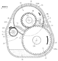
図1に示すように、減速機部Bは、複数の歯車(歯車軸)を有し、各歯車の回転軸が互いに平行に配置された、いわゆる平行軸歯車減速機30で構成される。本実施形態の平行軸歯車減速機30は、入力歯車31、中間歯車32および出力歯車33からなり、各歯車31〜33の回転軸(回転中心)O1〜O3は、図2に示すように、各回転軸O1〜O3を結ぶ直線が三角形状をなすように配置されている。より具体的には、出力歯車33の回転軸O3が最も下側に配置され、中間歯車32の回転軸O2が最も上側に配置され、入力歯車31の回転軸O1が回転軸O2,O3の略中間に配置されている。係る態様で各歯車31〜33を配置することにより、コンパクトな減速機30を実現できる。
As shown in FIG. 1, the reduction gear unit B includes a plurality of gears (gear shafts), so-called parallel shaft gear reduction gears 30, in which the rotation axes of the gears are arranged in parallel with each other. The parallel
また、出力歯車33と中間歯車32との噛合い点Mp、すなわち、減速機30における歯車同士の最終噛合い点は、出力歯車33の回転軸O3よりも上方に位置している。これは、減速機部Bを潤滑・冷却するためにケーシング22の減速機室22Bに充填される潤滑油70の撹拌抵抗の増大による減速機30の効率低下を避けるためである。
The meshing point Mp between the
この平行軸歯車減速機30では、入力歯車31の歯車部34と中間歯車32の大径歯車部35とが噛み合い、また、中間歯車32の小径歯車部36と出力歯車33の歯車部37とが噛み合っている。中間歯車32の大径歯車部35の歯数は、入力歯車31の歯車部34および中間歯車32の小径歯車部36の歯数よりも多く、出力歯車33の歯車部37の歯数は、中間歯車32の小径歯車部36の歯数よりも多い。係る構成から、本実施形態の平行軸歯車減速機30は、モータ回転軸25の回転を2段階で減速して車輪用軸受部Cに出力(伝達)する。
In the parallel
入力歯車31は、スプライン嵌合によってモータ回転軸25と一体回転可能に連結されており、軸方向の二箇所に離間して配置された転がり軸受42,43によってケーシング22に回転自在に支持されている。中間歯車32は軸方向の二箇所に離間して配置された転がり軸受44,45により、また、出力歯車33は軸方向の二箇所に離間して配置された転がり軸受46,47により、それぞれ、ケーシング22に回転自在に支持されている。
The
本実施形態の入力歯車31、中間歯車32および出力歯車33には、はすば歯車を用いている(図6を参照)。はすば歯車は、同時に噛合う歯数が多く、歯当たりが分散されるため、噛合い時の音が静かでトルク変動が少ないという利点を有する。従って、はすば歯車を用いれば、静粛かつトルク伝達効率に優れた平行軸歯車減速機30を実現する上で有利となる。
Helical gears are used as the
図1に示すように、車輪用軸受部Cは、いわゆる内輪回転タイプの車輪用軸受50で構成される。車輪用軸受50は、ハブ輪51および内輪52からなる内方部材53と、外輪54と、ボール57と、図示外の保持器とを備えた複列アンギュラ玉軸受からなる。詳細な図示は省略しているが、車輪用軸受50の内部空間には、潤滑剤としてのグリースが充填されている。軸受内部空間への異物侵入および軸受外部へのグリース漏洩を防止するため、車輪用軸受50の軸方向両端部にはシール部材が設けられている。
As shown in FIG. 1, the wheel bearing portion C includes a so-called inner ring rotating
ハブ輪51は、スプライン嵌合によって平行軸歯車減速機30を構成する出力歯車33と一体回転可能に連結されている。ハブ輪51のアウトボード側の端部外周にフランジ部51aが設けられ、このフランジ部51aに図示外の車輪(ブレーキディスクおよびホイール)が取り付けられる。また、ハブ輪51のインボード側の端部には、内輪52を加締め固定してなる加締め部51bが形成されている。この加締め部51bは、車輪用軸受50に対して予圧を付与する。
The
ハブ輪51の外周にアウトボード側の内側軌道面55が形成され、内輪52の外周にインボード側の内側軌道面55が形成されている。外輪54の内周には、両内側軌道面55,55に対応する複列の外側軌道面56が形成されており、対をなす内側軌道面55と外側軌道面56とで形成されるボールトラックに複数のボール57が組み込まれている。外輪54は、そのアウトボード側の端部から径方向外向きに延びるフランジ部を一体に有し、このフランジ部にボルト止めされたアタッチメント58を介してケーシング22にボルト止めされている。
An
以上の構成からなるインホイールモータ駆動装置21の全体的な作動態様を簡単に説明する。
The overall operation mode of the in-wheel
まず、電動モータ部Aにおいて、ステータ23に交流電流が供給されると、これに伴って生じる電磁力によりロータ24およびモータ回転軸25が回転する。モータ回転軸25の回転は、減速機部Bにおいて平行軸歯車減速機30(入力歯車31、中間歯車32および出力歯車33)によって減速された上で車輪用軸受50に伝達される。このように、モータ回転軸25の回転が、平行軸歯車減速機30によって減速された上で車輪用軸受50に伝達されるので、低トルクで高速回転型の電動モータ26を採用した場合でも、駆動輪としての後輪14(図7,8参照)に必要なトルクを伝達することができる。
First, in the electric motor unit A, when an alternating current is supplied to the
本実施形態では、電動モータ部Aを構成する電動モータ26に、ラジアルギャップ型の電動モータを採用しているが、電動モータ26としては、ステータ23とロータ24とが軸方向の隙間を介して対向配置される、いわゆるアキシャルギャップ型の電動モータを採用しても構わない。
In the present embodiment, a radial gap type electric motor is adopted as the
以上で説明したインホイールモータ駆動装置21において、ケーシング22の減速機収容室22Bには潤滑油70が充填されており(図2参照)、インホイールモータ駆動装置21の駆動時には、歯車31〜33の回転に伴って潤滑油70が減速機部Bの各部に供給されることにより、減速機部Bが潤滑・冷却される。
In the in-wheel
本実施形態のインホイールモータ駆動装置21は、減速機部Bを潤滑・冷却するための潤滑機構に主たる特徴があり、以下にその詳細を説明する。
The in-wheel
軽量・コンパクトなインホイールモータ駆動装置21を実現する上では、図2に示すように、減速機部Bの構成部品(歯車31〜33等)を密に配置すると共に、減速機室22Bが小型化されたケーシング22を採用し、平行軸歯車減速機30とケーシング22との間の隙間をできるだけ小さくすることが有効である。しかしながら、このような構成を採用すると、スペース上の制約から、オイルポンプやオイル配管等を必要とするような潤滑機構を減速機部Bに設置することはできない。そこで、本実施形態では、平行軸歯車減速機30を構成する歯車31〜33のうち、出力歯車33の歯車部37の一部を常時潤滑油に浸漬させた油浴状態とし、出力歯車33の回転に伴って掻き上げられる潤滑油を利用して出力歯車33と中間歯車32との噛合い点(最終噛合い点Mp)を効率良く潤滑・冷却すると共に、最終噛合い点Mpを潤滑した潤滑油を効率良く利用して他の歯車部等を潤滑・冷却可能とした。
In order to realize the lightweight and compact in-wheel
図2に示すように、ケーシング22の減速機室22Bには、所定量の潤滑油70(散点ハッチングで示す)が充填されており、ここでは、入力歯車31、中間歯車32および出力歯車33のうち、最も下側に配置される出力歯車33の歯車部37の一部を油浴状態にし得る程度の潤滑油70が充填されている。従って、前述した各歯車31〜33の配置態様から、入力歯車31の歯車部34、さらには中間歯車32の大径歯車部35および小径歯車部36は、減速機室22Bの底部に溜まった潤滑油70とは接触せず、出力歯車33の歯車部37のみが減速機室22Bの底部に溜まった潤滑油70と接触する。これにより、潤滑油70の撹拌抵抗の増大による平行軸歯車減速機30の効率低下を避けることができる。
As shown in FIG. 2, the
前述したとおり、ケーシング22のコンパクト化を図る観点から、平行軸歯車減速機30とケーシング22との間の隙間はできるだけ小さく設定される。ここでは、出力歯車33の歯先が隙間幅d=3〜20mm程度の隙間(径方向隙間)22Baを介してケーシング22の内壁面と対向するように、出力歯車33が減速機室22Bに配置される。また、中間歯車32の大径歯車部35の歯先が上記と同程度の隙間幅を有する隙間を介してケーシング22の内壁面と対向するように、中間歯車32が出力歯車33の上方に配置される。一方、入力歯車31は、その歯先円C1が、最終噛合い点Mpの接線Tと交わるようにして、中間歯車32および出力歯車33よりも車両の前方側に配置されている。
As described above, from the viewpoint of downsizing the
減速機室22Bには、出力歯車33の回転に伴って掻き上げられる潤滑油70を利用して、最終噛合い点Mp手前に油溜り72を形成するための油溜り形成部71が設けられる。これにより、出力歯車33の回転に伴って、減速機室22Bの底部に貯留された潤滑油70が出力歯車33とケーシング22との間の隙間22Baに沿って掻き上げられると、出力歯車33、中間歯車32および油溜り形成部71の協働により、最終噛合い点Mp手前に潤沢な潤滑油70を貯留してなる油溜り72が形成される。
The
本実施形態では、ケーシング22に、減速機室22Bの室内側に突出した突出部を一体的に設け、この突出部で油溜り形成部71を構成している。この油溜り形成部71は、最終噛合い点Mpの手前位置に油溜り72を適切に形成可能とするため、少なくとも一部(本実施形態では、油溜り形成部71の自由端側の一部)が、中間歯車32の最大歯先円(大径歯車部35の歯先円)C2の内径側に位置するように設けられる。なお、油溜り形成部71は、ケーシング22以外の部品で構成することも可能である。後述する他の実施形態においても同様である。ケーシング22以外の部品としては、例えば、ボルト等の締結部材や、油温計を挙げることができる。
In the present embodiment, the
以上の構成により、インホイールモータ駆動装置21の駆動時(厳密には、電気自動車11を前進移動させる方向に電動モータ26が回転駆動された時)には、減速機部Bが以下のようにして潤滑・冷却される。
With the above configuration, when the in-wheel
モータ回転軸25の出力を受けて入力歯車31、中間歯車32および出力歯車33が回転し(各歯車31〜33の回転方向は塗り潰し矢印を参照)、出力歯車33の回転に伴って減速機室22Bの底部に貯留された潤滑油70が出力歯車33とケーシング22との間の隙間22Baに沿って掻き上げられると(図2中の白抜き矢印を参照)、出力歯車33、中間歯車32および油溜り形成部71の協働により、最終噛合い点Mp手前に潤沢な潤滑油70が介在する油溜り72が形成される。そして、出力歯車33が継続して回転するのに伴い、最終噛合い点Mpは、油溜り72から次々に供給される潤滑油70によって潤滑・冷却される。最終噛合い点Mpに供給された潤滑油70は、最終噛合い点Mpと軸方向に隣接配置される転がり軸受45(図1参照)の他、出力歯車33を支持するアウトボード側の転がり軸受47(図1参照)にも供給され、これら転がり軸受45,47を潤滑・冷却する。
The
最終噛合い点Mpに供給された潤滑油70は、主に、最終噛合い点Mpの接線Tに沿って両歯車33,32の回転方向前方側に飛散する。そのため、両歯車33,32が回転すると、最終噛合い点Mpを潤滑した潤滑油70は、歯先円C1が、最終噛合い点Mpを挟んで油溜り72とは反対側(図2においては、最終噛合い点Mpよりも左側)で上記接線Tと交わるように配置された入力歯車31に向けて飛散し(図2中の白抜き矢印参照)、入力歯車31(の軸部)に供給される。入力歯車31の軸部に次々に供給される潤滑油70は、入力歯車31(の歯車部34)と中間歯車32(の大径歯車部35)との噛み合い部の他、入力歯車31のアウトボード側の端部を支持する転がり軸受43(図1参照)にも供給されてこれらを潤滑する。入力歯車31の軸部に供給された潤滑油70は、入力歯車31の回転によってその軸部付近のケーシング22内壁に飛散して流れ落ち、入力歯車31のインボード側の端部を支持する転がり軸受42にも供給される。また、入力歯車31を支持する転がり軸受け42,43の外径と最終噛合い点Mpの接線Tとが交わっていれば、入力歯車31の歯車部34を効率よく潤滑・冷却することができる。
The lubricating
以上のようにして、出力歯車33から入力歯車31まで潤滑油70を運び、入力歯車31の歯車部34および転がり軸受42,43に潤滑油70が供給されてこれらを潤滑・冷却する。このように、本発明では、減速機部B内にオイルポンプやオイル配管を設置せずとも、また、減速機30を構成する歯車31〜33の内部に給油孔等を設けずとも、減速機30の奥まった位置、すなわち、潤滑油70の油面および油浴状態の出力歯車33から離れて配置され、跳ねかけのみでは十分な給油が難しい入力歯車31(の歯車部34)、さらには入力歯車31を支持する転がり軸受42,43に対して潤滑油70を効率良く供給することができる。従って、本発明によれば、軽量・コンパクトでありながら、減速機部Bの各部を効率良く潤滑・冷却することができて信頼性に富むインホイールモータ駆動装置21を実現することができる。
As described above, the lubricating
以上、本発明の一実施形態に係るインホイールモータ駆動装置21について説明したが、本発明の実施の形態はこれに限られない。
The in-wheel
例えば、図3に示すように、減速機部Bには、最終噛合い点Mpの接線T上であって、最終噛合い点Mpと入力歯車31(出力歯車33と噛み合う中間歯車32よりも前段に配置される一の歯車)との間に、潤滑油70の流れを制御するための制御部73を設けても良い。このようにすれば、制御部73の形状や設置姿勢を適宜設定することにより、入力歯車31に対する潤滑油70の供給箇所や供給量を任意に調整することが可能となるので、入力歯車31の潤滑効率を高める上で有利となる。上記の制御部73は、油溜り形成部71と同様に、ケーシング22と一体に設けても良いし、ケーシング22以外の部品で構成しても良い。
For example, as shown in FIG. 3, in the speed reducer unit B, on the tangent line T of the final meshing point Mp, the final meshing point Mp and the input gear 31 (the
また、図4に示すように、油溜り形成部71は、出力歯車33の回転に伴って掻き上げられる潤滑油70を互いに異なる二方向に分流可能に設けることも可能である。この場合、出力歯車33が掻き上げた潤滑油70を、油溜り72を形成するために利用する他、中間歯車32の大径歯車部35を直接潤滑・冷却するために利用することが可能となる。これにより、中間歯車32の大径歯車部35を効率良く潤滑・冷却することができる。また、この場合、減速機30上方へ飛散した潤滑油70がケーシング22内壁に付着し易く、ケーシング22内壁に付着した潤滑油70は、ケーシング22内壁22を伝いながら減速機30全体に滴下する。従って、潤滑油70を任意の箇所に集中的に供給するだけではなく、減速機30全体に分散供給することができる。なお、図4に示す構成は、図2および図3に示す油溜り形成部71の付け根部に、出力歯車33の歯車部37とケーシング22との間に形成される隙間22Baと、中間歯車32の大径歯車部35とケーシング22との間に形成される隙間22Bbとを連通させるための切欠き74を設けることで形成している。
Further, as shown in FIG. 4, the oil
また、以上では、入力歯車31、中間歯車32および出力歯車33を有し、モータ回転軸25の回転を2段階で減速して車輪用軸受部Cに伝達する平行軸歯車減速機30(三軸タイプの平行軸歯車減速機30)に本発明を適用したが、本発明は、入力歯車31と中間歯車32との間に一又は複数の中間歯車が追加された、四軸以上の平行軸歯車減速機30に適用することも可能である。図5は、その一例を示すものであり、入力歯車31と中間歯車32との間に一の中間歯車39を追加してなる四軸タイプの平行軸歯車減速機30を示している。図5に示す中間歯車39は、他の歯車31〜33の回転軸O1〜O3と平行に配置された回転軸O4と、入力歯車31の歯車部34と噛み合う大径歯車部39aと、中間歯車32の大径歯車部35と噛み合う小径歯車部39bとを有する。図5に示す実施形態の特徴的構成は、図2を参照して説明した本発明の第1実施形態に係る平行軸歯車減速機30に順ずるので、詳細説明を省略する。
Further, in the above, the parallel shaft gear reducer 30 (three shafts) that has the
また、以上では、出力歯車33と噛み合う中間歯車32よりも前段に配置される一の歯車(図2では入力歯車31)の歯車部34の歯幅と、入力歯車31の歯車部34と噛み合う中間歯車32の大径歯車部35の歯幅とを同一としたが(図1参照)、入力歯車31の歯車部34の歯幅は、図6に示すように、中間歯車32の大径歯車部35の歯幅よりも大きくしても良い。このようにすれば、主に最終噛合い点Mpの接線Tに沿う方向に飛散する潤滑油70を入力歯車31の歯車部34に直接的に供給することが可能となるので、入力歯車31の潤滑・冷却効率を高める上で有利となる。
Further, in the above description, the tooth width of the
また、以上では、ケーシング22に収容された電動モータ部Aおよび減速機部Bと、ケーシング22に取り付けられた車輪用軸受部Cとを備えたインホイールモータ駆動装置21に本発明を適用したが、本発明は、インホイールモータ駆動装置21以外の車両駆動装置、例えば、電動モータ部Aおよび減速機部Bを収容したケーシングが車体に取り付けられ、減速機部Bの出力がドライブシャフトを介して車輪(車輪用軸受)に伝達される、いわゆるオンボードタイプの車両駆動装置にも適用することができる。
Further, in the above, the present invention is applied to the in-wheel
本発明は前述した実施形態に何ら限定されるものではなく、本発明の要旨を逸脱しない範囲内において、さらに種々なる形態で実施し得る。すなわち、本発明の範囲は、特許請求の範囲によって示され、さらに特許請求の範囲に記載の均等の意味、および範囲内のすべての変更を含む。 The present invention is not limited to the above-described embodiments, and can be carried out in various forms without departing from the gist of the present invention. That is, the scope of the present invention is defined by the claims, and includes equivalent meanings in the claims and all modifications within the scope.
21 インホイールモータ駆動装置
22 ケーシング
22B 減速機室
26 電動モータ
30 平行軸歯車減速機
31 入力歯車
32 中間歯車
33 出力歯車
34 歯車部
35 大径歯車部
36 小径歯車部
37 歯車部
50 車輪用軸受
70 潤滑油
71 油溜り形成部
72 油溜り
73 制御部
A 電動モータ部
B 減速機部
C 車輪用軸受部
C1 入力歯車の歯先円
C2 中間歯車の最大歯先円
Mp 噛合い点
O1 回転軸
O2 回転軸
O3 回転軸
T 接線
21 in-wheel
Claims (8)
前記ケーシング内に、前記出力歯車の歯車部の一部を油浴状態とする潤滑油が充填され、
前記出力歯車の回転に伴って掻き上げられる潤滑油を利用して前記出力歯車と前記中間歯車の噛合い点手前に油溜りを形成するための油溜り形成部が設けられ、該油溜り形成部の少なくとも一部が、前記出力歯車と噛み合う前記中間歯車の最大歯先円の内側に位置していることを特徴とする車両駆動装置。 An electric motor unit, a speed reducer unit, and a casing accommodating the electric motor unit and the speed reducer unit, wherein the speed reducer unit is an input gear having rotation shafts arranged in parallel, and one or more intermediate gears. , And a vehicle drive device composed of a parallel shaft gear reducer having an output gear,
The casing is filled with a lubricating oil that places a part of the gear portion of the output gear in an oil bath state,
An oil sump forming portion for forming an oil sump is provided before the meshing point of the output gear and the intermediate gear by using the lubricating oil scraped up by the rotation of the output gear. At least a part of which is located inside a maximum addendum circle of the intermediate gear that meshes with the output gear.
Priority Applications (2)
| Application Number | Priority Date | Filing Date | Title |
|---|---|---|---|
| JP2017174694A JP6725464B2 (en) | 2017-09-12 | 2017-09-12 | Vehicle drive |
| PCT/JP2018/033677 WO2019054381A1 (en) | 2017-09-12 | 2018-09-11 | Vehicle drive device |
Applications Claiming Priority (1)
| Application Number | Priority Date | Filing Date | Title |
|---|---|---|---|
| JP2017174694A JP6725464B2 (en) | 2017-09-12 | 2017-09-12 | Vehicle drive |
Publications (2)
| Publication Number | Publication Date |
|---|---|
| JP2019049338A JP2019049338A (en) | 2019-03-28 |
| JP6725464B2 true JP6725464B2 (en) | 2020-07-22 |
Family
ID=65906022
Family Applications (1)
| Application Number | Title | Priority Date | Filing Date |
|---|---|---|---|
| JP2017174694A Expired - Fee Related JP6725464B2 (en) | 2017-09-12 | 2017-09-12 | Vehicle drive |
Country Status (1)
| Country | Link |
|---|---|
| JP (1) | JP6725464B2 (en) |
Families Citing this family (1)
| Publication number | Priority date | Publication date | Assignee | Title |
|---|---|---|---|---|
| CN115263487B (en) * | 2022-09-02 | 2024-04-16 | 中国重汽集团济南动力有限公司 | Oil pumping device without additional power |
-
2017
- 2017-09-12 JP JP2017174694A patent/JP6725464B2/en not_active Expired - Fee Related
Also Published As
| Publication number | Publication date |
|---|---|
| JP2019049338A (en) | 2019-03-28 |
Similar Documents
| Publication | Publication Date | Title |
|---|---|---|
| JP5374215B2 (en) | Cycloid reducer, in-wheel motor drive device, and vehicle motor drive device | |
| JP5778433B2 (en) | In-wheel motor drive device | |
| JP2016070358A (en) | Lubrication device of in-wheel motor drive unit | |
| JP2012171420A (en) | Device for driving in-wheel motor | |
| JP6781608B2 (en) | In-wheel motor drive | |
| JP6725464B2 (en) | Vehicle drive | |
| WO2021095418A1 (en) | In-wheel motor drive device | |
| WO2019054381A1 (en) | Vehicle drive device | |
| WO2019208641A1 (en) | Vehicle power unit | |
| JP2017159883A (en) | In-wheel motor driving device | |
| JP2019156392A (en) | In-wheel motor drive device | |
| JP6725466B2 (en) | Vehicle drive | |
| WO2019172255A1 (en) | Vehicle driving device | |
| JP2017052480A (en) | In-wheel motor drive device | |
| JP6333579B2 (en) | In-wheel motor drive device | |
| JP2019051901A (en) | Vehicle drive device | |
| JP2017165267A (en) | In-wheel motor drive device | |
| WO2019177104A1 (en) | Vehicle drive device | |
| JP6843511B2 (en) | In-wheel motor drive | |
| JP2016210231A (en) | In-wheel motor drive unit | |
| WO2018083810A1 (en) | In-wheel motor drive device | |
| JP6917849B2 (en) | In-wheel motor drive | |
| JP2020046055A (en) | In-wheel motor drive device | |
| JP2015175410A (en) | In-wheel motor driving device | |
| JP7028671B2 (en) | Vehicle drive |
Legal Events
| Date | Code | Title | Description |
|---|---|---|---|
| A621 | Written request for application examination |
Free format text: JAPANESE INTERMEDIATE CODE: A621 Effective date: 20200316 |
|
| TRDD | Decision of grant or rejection written | ||
| A01 | Written decision to grant a patent or to grant a registration (utility model) |
Free format text: JAPANESE INTERMEDIATE CODE: A01 Effective date: 20200611 |
|
| A61 | First payment of annual fees (during grant procedure) |
Free format text: JAPANESE INTERMEDIATE CODE: A61 Effective date: 20200625 |
|
| R150 | Certificate of patent or registration of utility model |
Ref document number: 6725464 Country of ref document: JP Free format text: JAPANESE INTERMEDIATE CODE: R150 |
|
| LAPS | Cancellation because of no payment of annual fees |