JP6723121B2 - Train operation support device - Google Patents
Train operation support device Download PDFInfo
- Publication number
- JP6723121B2 JP6723121B2 JP2016175181A JP2016175181A JP6723121B2 JP 6723121 B2 JP6723121 B2 JP 6723121B2 JP 2016175181 A JP2016175181 A JP 2016175181A JP 2016175181 A JP2016175181 A JP 2016175181A JP 6723121 B2 JP6723121 B2 JP 6723121B2
- Authority
- JP
- Japan
- Prior art keywords
- pattern
- section
- driving
- information
- performance
- Prior art date
- Legal status (The legal status is an assumption and is not a legal conclusion. Google has not performed a legal analysis and makes no representation as to the accuracy of the status listed.)
- Active
Links
Images


Classifications
-
- B—PERFORMING OPERATIONS; TRANSPORTING
- B61—RAILWAYS
- B61L—GUIDING RAILWAY TRAFFIC; ENSURING THE SAFETY OF RAILWAY TRAFFIC
- B61L25/00—Recording or indicating positions or identities of vehicles or vehicle trains or setting of track apparatus
- B61L25/02—Indicating or recording positions or identities of vehicles or vehicle trains
- B61L25/04—Indicating or recording train identities
-
- B—PERFORMING OPERATIONS; TRANSPORTING
- B60—VEHICLES IN GENERAL
- B60L—PROPULSION OF ELECTRICALLY-PROPELLED VEHICLES; SUPPLYING ELECTRIC POWER FOR AUXILIARY EQUIPMENT OF ELECTRICALLY-PROPELLED VEHICLES; ELECTRODYNAMIC BRAKE SYSTEMS FOR VEHICLES IN GENERAL; MAGNETIC SUSPENSION OR LEVITATION FOR VEHICLES; MONITORING OPERATING VARIABLES OF ELECTRICALLY-PROPELLED VEHICLES; ELECTRIC SAFETY DEVICES FOR ELECTRICALLY-PROPELLED VEHICLES
- B60L3/00—Electric devices on electrically-propelled vehicles for safety purposes; Monitoring operating variables, e.g. speed, deceleration or energy consumption
- B60L3/12—Recording operating variables ; Monitoring of operating variables
-
- B—PERFORMING OPERATIONS; TRANSPORTING
- B60—VEHICLES IN GENERAL
- B60L—PROPULSION OF ELECTRICALLY-PROPELLED VEHICLES; SUPPLYING ELECTRIC POWER FOR AUXILIARY EQUIPMENT OF ELECTRICALLY-PROPELLED VEHICLES; ELECTRODYNAMIC BRAKE SYSTEMS FOR VEHICLES IN GENERAL; MAGNETIC SUSPENSION OR LEVITATION FOR VEHICLES; MONITORING OPERATING VARIABLES OF ELECTRICALLY-PROPELLED VEHICLES; ELECTRIC SAFETY DEVICES FOR ELECTRICALLY-PROPELLED VEHICLES
- B60L2200/00—Type of vehicles
- B60L2200/26—Rail vehicles
-
- B—PERFORMING OPERATIONS; TRANSPORTING
- B60—VEHICLES IN GENERAL
- B60L—PROPULSION OF ELECTRICALLY-PROPELLED VEHICLES; SUPPLYING ELECTRIC POWER FOR AUXILIARY EQUIPMENT OF ELECTRICALLY-PROPELLED VEHICLES; ELECTRODYNAMIC BRAKE SYSTEMS FOR VEHICLES IN GENERAL; MAGNETIC SUSPENSION OR LEVITATION FOR VEHICLES; MONITORING OPERATING VARIABLES OF ELECTRICALLY-PROPELLED VEHICLES; ELECTRIC SAFETY DEVICES FOR ELECTRICALLY-PROPELLED VEHICLES
- B60L2240/00—Control parameters of input or output; Target parameters
- B60L2240/10—Vehicle control parameters
- B60L2240/12—Speed
-
- B—PERFORMING OPERATIONS; TRANSPORTING
- B60—VEHICLES IN GENERAL
- B60L—PROPULSION OF ELECTRICALLY-PROPELLED VEHICLES; SUPPLYING ELECTRIC POWER FOR AUXILIARY EQUIPMENT OF ELECTRICALLY-PROPELLED VEHICLES; ELECTRODYNAMIC BRAKE SYSTEMS FOR VEHICLES IN GENERAL; MAGNETIC SUSPENSION OR LEVITATION FOR VEHICLES; MONITORING OPERATING VARIABLES OF ELECTRICALLY-PROPELLED VEHICLES; ELECTRIC SAFETY DEVICES FOR ELECTRICALLY-PROPELLED VEHICLES
- B60L2250/00—Driver interactions
- B60L2250/16—Driver interactions by display
-
- B—PERFORMING OPERATIONS; TRANSPORTING
- B60—VEHICLES IN GENERAL
- B60L—PROPULSION OF ELECTRICALLY-PROPELLED VEHICLES; SUPPLYING ELECTRIC POWER FOR AUXILIARY EQUIPMENT OF ELECTRICALLY-PROPELLED VEHICLES; ELECTRODYNAMIC BRAKE SYSTEMS FOR VEHICLES IN GENERAL; MAGNETIC SUSPENSION OR LEVITATION FOR VEHICLES; MONITORING OPERATING VARIABLES OF ELECTRICALLY-PROPELLED VEHICLES; ELECTRIC SAFETY DEVICES FOR ELECTRICALLY-PROPELLED VEHICLES
- B60L2260/00—Operating Modes
- B60L2260/40—Control modes
- B60L2260/42—Control modes by adaptive correction
Description
本発明は、列車の運転操作を案内する情報を運転士に提供することで列車の運転を支援する列車運転支援装置に関する。 The present invention relates to a train driving support device that supports train driving by providing a driver with information that guides train driving operations.
鉄道システムにおいて、列車の運転士はダイヤに基づいて、制限速度を遵守し到着時刻や到着位置を正確に保つための判断を適宜行いながら運転操作を実施している。このような鉄道システムの運転に際して、運転操作の切替点などの情報を提供することで、運転士の運転操作を支援し、省エネや乗り心地向上を実現する走行支援装置が提案・実用化されている。運転支援装置は目標とする走行パターンを算出し、その目標走行パターンに沿うような運転操作の情報を運転士に提供する。ここで走行パターンとは、走行区間における位置と列車の速度の関係である。 In a railway system, a train driver carries out a driving operation based on a timetable while appropriately observing a speed limit and making a judgment for keeping an accurate arrival time and arrival position. When driving such a railway system, a driving support device that supports the driving operation of the driver by providing information such as the switching point of the driving operation to save energy and improve riding comfort has been proposed and put into practical use. There is. The driving support device calculates a target traveling pattern and provides the driver with information on a driving operation that follows the target traveling pattern. Here, the traveling pattern is the relationship between the position in the traveling section and the speed of the train.
本技術分野の背景技術として、特許文献1がある。この公報には、「理解度データを全ての運転士にわたって分析し、分析された全ての前記理解度データの数に対し、予め定める閾値を超える数の前記理解度データが、前記操作内容が現状維持の状態にあると判断される場合、前記ランカーブ作成装置によって作成される前記ランカーブデータの内容が、前記操作履歴データの内容に近づくように、前記入力パラメータを修正することを特徴とする」と記載されている(特許文献1の請求項5参照)。
As a background art in this technical field, there is
運転士が列車を運転する鉄道システムにおいては、運転士は制限速度を遵守し到着時刻や到着位置を正確に保つための判断を行う。このため、運転支援装置が提供する運転支援情報は、制限速度の遵守や、到着時刻・位置の精度に関連する判断を運転士が行う場面において認知負荷の小さな情報であることが望ましい。 In a railway system in which a driver drives a train, the driver observes the speed limit and makes a judgment to keep the arrival time and the arrival position accurately. For this reason, it is desirable that the driving assistance information provided by the driving assistance device has a small cognitive load when the driver makes a decision regarding speed limit compliance and arrival time/position accuracy.
特許文献1による発明では、ランカーブ作成装置で数値計算により作成されるランカーブデータが操作履歴データの内容に近づくように、ランカーブ作成装置がランカーブデータを作成する際に使用する入力パラメータを修正する。例えばランカーブを作成時の目的関数が省エネを重視するか走行の余裕時分を重視するかの重みづけのパラメータを調整することができる。この調整によって運転支援装置から提供される情報を運転士が所望する情報に調整可能となり、運転士が運転にあたって省エネを重視するか、走行の余裕時分を重視するかが時間的に変化したとしても、運転士の想定する走行時分と支援情報が前提とする走行時分を一致させることが出来るようになる。結果として認知負荷が小さい運転支援情報の提供が可能となる。
In the invention according to
一方、運転士が制限速度区間や停車駅直前の区間で減速する際の運転操作は、制限速度の遵守や到着時刻・位置の精度に関わる操作であり、区間ごとに各区間における勾配やカーブなどの特徴を考慮した様々なノウハウが存在する。運転士はこれらのノウハウを反映した運転操作を行うが、こうしたノウハウは区間の特徴によって異なり、さらに運転士毎に異なる可能性もあるため、複雑かつモデル化が困難である。このため、数値計算により得られたランカーブのみに基づいて運転支援情報を決定する従来の方法では、制限速度区間や停車駅直前の区間において、運転支援情報と運転士の判断が乖離し、運転士の認知負荷が小さい運転支援情報の提供が困難となるおそれがある。 On the other hand, the driving operation when the driver decelerates in the speed limit section or the section immediately before the stop station is an operation related to the compliance with the speed limit and the accuracy of arrival time and position, such as the slope and curve in each section. There are various know-how that take into account the characteristics of. The driver performs a driving operation that reflects these know-how, but since such know-how varies depending on the characteristics of the section and may also vary from driver to driver, it is complicated and difficult to model. Therefore, in the conventional method of determining the driving support information based only on the run curve obtained by the numerical calculation, in the speed limit section or the section immediately before the stop station, the driving support information and the judgment of the driver deviate, and the driver It may be difficult to provide driving support information with a small cognitive load.
本発明の目的は、運転士の運転操作を踏まえた運転支援を可能とし、それにより複雑な運転が必要な区間についても運転士の認知負荷が小さい運転支援情報の提供を可能とすることである。 An object of the present invention is to enable driving support based on a driver's driving operation, thereby providing driving support information with a small driver's cognitive load even in a section where complicated driving is required. ..
上記課題を解決するために、例えば特許請求の範囲に記載の構成を採用する。 In order to solve the above problems, for example, the configurations described in the claims are adopted.
本願は上記課題を解決する手段を複数含んでいるが、その一例を挙げるならば、前記列車の物理的な挙動を再現するために必要な情報である車両特性と、路線又はダイヤの情報である路線条件に基づいて、制約条件を満たしつつ、省エネ性能や運転操作性や乗り心地に関する評価指標を少なくとも1つ含み乗客あるいは列車の事業者にとって望ましい状態にあるときに小さな値を出力する目的関数を最小化する組み合わせ最適化演算によってシミュレーションパターンを生成するシミュレーションパターン生成部と、前記シミュレーションパターンと実績パターン情報に基づいて、前記シミュレーションパターンと前記実績パターン情報の類似度を算出して類似度が高い第1の区間と類似度が低い第2の区間を判定して類似度情報として出力する類似度算出部と、前記実績パターン情報と前記類似度情報に基づいて前記第1の区間における前記シミュレーションパターンを前記第2の区間で前記実績パターンと接続することを制約条件とした前記組合せ最適化演算により計算される区間シミュレーションパターンを生成する区間シミュレーションパターン生成部と、前記実績パターン情報と前記区間情報と前記区間シミュレーションパターンから運転基準パターンを生成する組合わせパターン生成部とを備え、前記組合わせパターン生成部は、前記第1の区間では前記区間シミュレーションパターンを、第2の区間では実績パターンを組み合わせたパターンを運転基準パターンとして生成することを特徴とする。 The present application includes a plurality of means for solving the above problems, and one example thereof is a vehicle characteristic that is information necessary for reproducing the physical behavior of the train, and information on a route or a schedule. An objective function that outputs a small value when it is in a desirable state for passengers or train operators, including at least one evaluation index related to energy-saving performance, driving operability, and riding comfort, while satisfying the constraint conditions based on the route conditions. A simulation pattern generation unit that generates a simulation pattern by a combination optimization operation that minimizes, and calculates a similarity between the simulation pattern and the performance pattern information based on the simulation pattern and the performance pattern information. A second section having a low similarity to the first section and outputting the second section as similarity information; and the simulation pattern in the first section based on the actual pattern information and the similarity information. A section simulation pattern generation unit that generates a section simulation pattern calculated by the combination optimization calculation under the constraint that connecting to the result pattern in the second section is a constraint condition, the result pattern information, the section information, and A combination pattern generation unit that generates an operation reference pattern from a section simulation pattern, wherein the combination pattern generation unit is a pattern that combines the section simulation pattern in the first section and the actual pattern in the second section. Is generated as an operation reference pattern.
本発明によれば、運転支援装置が支援情報を出力する場合の基準とする走行パターンは複雑な運転が必要な区間については運転士が実際に操作した実績パターンを採用しつつ、それ以外の箇所を最適化したパターンとなる。これによって、乖離が大きくなる区間では運転士のノウハウを反映した運転操作を基本としつつ、駅間全体として省エネとなるような運転を支援することが可能となる。 According to the present invention, the driving pattern that is used as a reference when the driving support device outputs the support information is the actual pattern that the driver actually operated for the section where complicated driving is required, while other points are used. The pattern is optimized. This makes it possible to support driving that saves energy as a whole between stations, while basically using driving operations that reflect the know-how of the driver in sections where the deviation is large.
以下、実施例を図面を用いて説明する。 Embodiments will be described below with reference to the drawings.
図1は、本実施例の第1の実施の形態である車両システムの構成図である。車両システムは車両の位置を検知する車両位置検知手段11と車両速度検知手段12と、運転支援装置100を含む。車両位置検知手段11は車両の位置情報を検知して運転支援装置100に送信する。車両速度検知手段12は車両の速度情報を検知して運転支援装置100に送信する。運転支援装置100は現在位置から目的地点までの走行パターン情報を生成して運転基準パターン情報として出力する。図2は、本実施例における実施例の運転支援装置100の構成図である。運転支援装置はシミュレーションパターン生成部110と、類似度算出部120と、区間シミュレーションパターン生成部130と、組合せパターン生成部140からなり、現在位置から目的地点までの走行パターン情報を生成する。
FIG. 1 is a configuration diagram of a vehicle system that is a first embodiment of the present embodiment. The vehicle system includes a vehicle
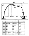
走行パターンは、列車が現在位置から目的地点に到着するまでの速度の変化であり、図3の301に示すように横軸に位置、縦軸に各位置における速度をとったグラフで表すことができる。さらに図3の302に走行パターン情報を表として記述した例を示す。走行パターン情報は走行パターンを一意に定めるのに必要な情報を列挙したものである。各行には現在時刻を基準とした時刻、位置、速度、運転モードの情報を含む。図3の302で示した例では、走行パターン情報を0.5[秒]毎に一定の間隔で記録しているが、走行パターン情報は走行パターンを一意に定めるのに十分な時間的精度で記録してあれば0.5[秒]間隔でなくてもよく、また記録する時間は等間隔でなくてもよい。 The traveling pattern is a change in speed from the current position until the train arrives at the destination, and can be represented by a graph in which the horizontal axis indicates the position and the vertical axis indicates the speed at each position, as indicated by 301 in FIG. it can. Further, an example in which the traveling pattern information is described as a table in 302 of FIG. 3 is shown. The traveling pattern information is a list of information necessary for uniquely determining the traveling pattern. Each row includes information on time, position, speed, and operation mode based on the current time. In the example indicated by 302 in FIG. 3, the traveling pattern information is recorded at regular intervals of 0.5 [second], but the traveling pattern information has sufficient time accuracy to uniquely determine the traveling pattern. If they are recorded, the intervals may not be 0.5 [seconds], and the recording times may not be even intervals.
シミュレーションパターン生成部110は、シミュレーション条件1aに基づいて、例えば組み合わせ最適化演算によって走行パターン情報を生成して、シミュレーションパターン1bとして出力する。ここでシミュレーション条件1aは現在の列車位置から到着地点までの列車の走行を計算するのに必要な情報であり、車両特性と路線条件からなる。車両特性は列車の物理的な挙動を再現するために必要な情報であり、例えば、列車の総重量、列車長、列車の引張力、列車の制動力、列車の力行時の効率および制動時の効率の情報である。路線条件は走行パターンの生成に必要な路線やダイヤの情報であり、例えば、出発駅の位置情報、到着地点の位置情報、出発駅から到着地点間の勾配情報、出発駅から到着地点間の曲線情報、出発駅から到着地点間の速度制限情報、出発駅から到着地点間で満たすべき既定の走行時分の情報である。また、組み合わせ最適化演算とは、位置ごとの速度制限や到着地点までの規定の走行時間Ttといった制約条件を満たしつつ、列車の走行時の消費電力量や乗り心地および操作性のうち、少なくとも一つを含む目的関数を最小化する走行パターン情報を導出する演算処理のことをいう。ここで目的関数は消費電力量に関する関数FE、乗り心地に関する関数FRおよび操作性に関する関数FCのうち少なくとも一つ以上の組合せで表される。関数はそれぞれ対応する項目がより望ましい状態にあるときは小さな値を取る関数である。例えばFEは消費電力量、FRは速度の二回微分として表される加加速度の絶対値の合計、FCは運転操作回数の合計とすることが出来、目的関数をFE+FR+FCとすることができる。このときそれぞれの目的関数の値が小さいことは、鉄道事業者あるいは乗客にとって望ましい状態であることを示す。また、目的関数の最小化とは、目的関数が走行パターン情報に応じて変化することから、列車の性能や路線条件および規定の走行時間Ttといった制約条件下で実現可能な組み合わせが最小となる走行パターン情報を探索することである。なお、FRおよび、FCは上記の関数形に限らず、例えばFRは加加速度の絶対値の最大値をとっても良いし、走行中の加減速の回数としてもよく、FCは単位時間あたりの運転操作の頻度や規定時間(例えば10秒)以内に運転操作の切り替えが必要である回数としてもよい。要は列車の運営事業者あるいは乗客にとって望ましい状態であるときに小さな値をとる関数であれば何でもよい。また、目的関数もFE、FR、FCの和でなくてもよく、FE、FR、FCの少なくとも一つを含む関数であり含まれる要素に対して単調増加となる関数であればよい。なお、組合わせ最適化演算にあたっては目的関数の値を対応する項目がより望ましい状態にあるときは大きな値を取る関数であるとし、その目的関数の最大値を求めることにしても結果的には同様である。
The simulation
類似度算出部120は、現在位置から到着地点までの区間毎に、シミュレーションパターン1bと、実績パターン1cとの類似度を算出し、類似度が高い第1の区間と類似度が低い第2の区間を判定して類似度情報1dとして区間シミュレーションパターン生成部に出力する。
The
ここで、実績パターンとは、運転士が実際に操作した列車の走行区間における位置と前記列車の速度の関係の情報である。 Here, the performance pattern is information on the relationship between the position of the train actually operated by the driver in the traveling section and the speed of the train.
図4に実績パターンの例を表として示す。実績パターンは走行パターン情報と識別情報とからなる。ここで走行パターン情報は図3の302に示した情報と同等の情報であり、識別情報は、ある走行実績を一意に特定するための情報である。識別情報は具体的には、走行実績が記録された日時・記録時の走行路線および走行した駅間の情報などを含む。また識別情報には走行実績が記録された日時の天候情報、乗車率など列車の運行に関係する情報を含んでもよく、また列車の運行に関係する他の情報(運転士を特定する運転士IDなど)を含んでもよい。さらに識別情報は目的関数に対応する消費電力量や乗り心地を表す指数などの情報を含んでもよい。 FIG. 4 shows an example of the performance pattern as a table. The performance pattern includes traveling pattern information and identification information. Here, the traveling pattern information is equivalent to the information shown in 302 of FIG. 3, and the identification information is information for uniquely identifying a certain traveling record. Specifically, the identification information includes the date and time when the travel record was recorded, the travel route at the time of recording and the information between the traveled stations. Further, the identification information may include information related to train operation such as weather information at the date and time when the travel record was recorded, boarding rate, and other information related to train operation (driver ID for identifying a driver. Etc.) may be included. Further, the identification information may include information such as an amount of power consumption corresponding to the objective function and an index indicating the riding comfort.
類似度算出部120においてある区間が第1の区間と判定されることは、その区間においてシミュレーションパターンと実績パターンが類似することを意味する。このためシミュレーションパターンを運転士に提示した際に認知負荷が小さいと考えられ、シミュレーションパターンおよびシミュレーションパターンを調整したパターンを運転支援情報に使用可能であることを示す。一方で第2の区間と判定された区間ではシミュレーションパターンと実績パターンが類似でないことを意味する。このため、第2の区間ではシミュレーションパターンを運転士に提示することは認知負荷の増加を招くため、シミュレーションパターンの提示を避けて実績パターンを提示する方が望ましいことを示す。
The determination of a certain section as the first section by the
区間シミュレーションパターン生成部130はシミュレーション条件1aと類似度算出部120が算出した類似度情報1dに基づいて、区間シミュレーションパターン1eを生成する。区間シミュレーションパターン1eは類似度情報1dにおける第2の区間で実績パターン1cと接続することを制約条件とした組合せ最適化により計算される。
The section simulation
ここで、実績パターン1cが一つ以上存在する場合、区間シミュレーションパターン生成部130は実績パターン1cのそれぞれに対応した区間シミュレーションパターン1eを計算する。なお、このとき類似度情報1dにおいて第2の区間と判定された不連続な区間がN区間(N≧2)存在する場合には、それぞれの区間で別の実績パターン1cを組み合わせてもよく、実績パターン1cがM通り存在する場合、MのN乗通りの区間シミュレーションパターン1eを生成することができる。
Here, when there is one or more
組合せパターン生成部140は、実績パターン1cと、類似度算出部120から受け取った類似度情報1dと、区間シミュレーションパターン生成部から受け取った区間シミュレーションパターン1eに基づいて、運転基準パターン1fを選択する。このとき、実績パターン1cあるいは区間シミュレーションパターン1eが複数存在する場合には実績パターン1cあるいはその組み合わせにより生成される実績パターンと、実績パターンに対応した区間シミュレーションパターン1eの組合せのうち、規定された目標走行時分Ttを遵守し、かつ目的関数を最小化する組み合わせを選択して運転基準パターン1fとして出力する。
The combination
類似度算出部120の動作を図5に示す。類似度算出部120は現在位置から到着地点までの各位置において実績パターンごとに一致判定を実施し、類似度を算出する。図5には実績パターンが複数の場合の処理を示すが、実績パターンが1つであったとしても、同一の処理で類似度を算出可能である。
The operation of the
以下のステップS501〜S506を現在位置から到着地点までの各位置Xに関して実行する。 The following steps S501 to S506 are executed for each position X from the current position to the arrival point.
ステップS501
位置Xを更新し、位置Xを基準としたシミュレーションパターンの運転操作情報を取得する。運転操作情報には位置Xでの運転操作Cx1と、次の運転操作Ca1、前の運転操作Cb1が含まれる。
Step S501
The position X is updated, and the driving operation information of the simulation pattern based on the position X is acquired. The driving operation information includes the driving operation Cx1 at the position X, the next driving operation Ca1, and the previous driving operation Cb1.
運転操作とは運転士の操作を示す情報で、力行のノッチ数(例えば、図6のS620の例では力行5ノッチ)、ブレーキのノッチ数(例えば、図6のS626のP611の例ではブレーキ4ノッチ)、定速、惰行からなる。 The driving operation is information indicating the operation of the driver, and includes the number of notches for power running (for example, 5 notches for S620 in FIG. 6) and the number of notches for braking (for example, brake 4 for P611 in S626 of FIG. 6). Notch), constant speed, coasting.
ここでCx1と異なる運転操作が行われている位置の集合をZとして、Ca1、Cb1を次のように定める。Zのうち位置Xより現在位置側にあり、かつ位置Xにもっとも近い地点で実施されている操作をCb1とする。また、Zのうち位置Xより到着位置側にあり、かつ位置Xにもっとも近い地点で実施されている操作をCa1とする。Ca1、Cb1ともに、Z中に該当する地点が存在しない場合には、それぞれCx1に等しいものと定める。ステップS502に進む。 Here, assuming that a set of positions where a driving operation different from Cx1 is performed is Z, Ca1 and Cb1 are defined as follows. An operation which is on the current position side of the position X of Z and is performed closest to the position X is defined as Cb1. Further, an operation performed at a position closest to the position X on the arrival position side of the position X in Z is Ca1. When there is no corresponding point in Z for both Ca1 and Cb1, it is determined to be equal to Cx1. It proceeds to step S502.
ステップS502
実績パターンを取得する。
Step S502
Get the achievement pattern.
ステップS503
位置Xを基準とした現在の実績パターンの運転操作情報を取得する。運転操作情報には位置Xでの運転操作Cx2が含まれる。ステップS504に進む。
Step S503
The driving operation information of the current performance pattern with reference to the position X is acquired. The driving operation information includes the driving operation Cx2 at the position X. It proceeds to step S504.
ステップS504
現在の実績パターンの位置Xにおける一致判定結果を、次の式の真偽として設定する。
Step S504
The coincidence determination result at the position X of the current performance pattern is set as the truth of the following equation.
「Cx2が、Cx1、Ca1、Cb1のうち、少なくとも一つと一致する」
現在の実績パターンが最後の実績パターンであればステップS505に進む。最後の実績パターンでない場合にはS502に進む。
“Cx2 matches at least one of Cx1, Ca1, and Cb1.”
If the current performance pattern is the last performance pattern, the process proceeds to step S505. If it is not the last performance pattern, the process proceeds to S502.
ステップS505
位置Xにおける一致判定結果が真である実績パターンの割合が基準割合以上であるかを判定する。基準割合は例えば50%とすることが出来る。判定結果が真の場合はステップS506に進み、偽の場合はステップS507に進む。
Step S505
It is determined whether or not the proportion of the performance pattern in which the match determination result at the position X is true is equal to or higher than the reference proportion. The reference ratio can be set to 50%, for example. If the determination result is true, the process proceeds to step S506, and if the determination result is false, the process proceeds to step S507.
ステップS506
位置Xにおける区間情報を第1の区間に設定する。位置Xが到着地点に一致する場合は処理終了し、一致しない場合にはステップS501に進む。
Step S506
The section information at the position X is set to the first section. If the position X coincides with the arrival point, the process ends, and if they do not coincide, the process proceeds to step S501.
ステップS507
位置Xにおける区間情報を第2の区間に設定する。位置Xが到着地点に一致する場合は処理終了し、一致しない場合にはステップS501に進む。
Step S507
The section information at the position X is set to the second section. If the position X coincides with the arrival point, the process ends, and if they do not coincide, the process proceeds to step S501.
ステップS504における一致判定の例を図6に示す。601はシミュレーションパターンP611と実績パターンP612をグラフとして表した図であり、S620〜S627は出発地点から到着地点までに存在する地点を表す。602は地点S620〜S627におけるP611とP612の運転操作および一致判定の結果を表したものである。点S620〜S624においては、P612の運転操作はP611の各地点の運転操作あるいはその前後の運転操作と一致するため、一致判定結果は「一致」となる、一方で点S625〜S627においては一致するものがないため、一致判定結果は「不一致」となる。
FIG. 6 shows an example of matching determination in step S504. 601 is a diagram showing the simulation pattern P611 and the performance pattern P612 as a graph, and S620 to S627 represent points existing from the departure point to the arrival point.
区間シミュレーションパターン生成部130の動作を図7に示す。なお、ここでは第2の区間と判定された不連続な区間が複数存在し、その組み合わせを考慮する場合の動作を記載する。
The operation of the section simulation
ステップS701
第2の区間と判定された不連続な区間数Nを算出し、M通りの実績パターン1cを区間毎に組合わせたMのN乗通りの実績組合せリストを設定。ステップS702に進み、実績組合せ数だけステップS702〜ステップ704を繰り返す。
Step S701
The number N of discontinuous sections determined to be the second section is calculated, and an M-th number of actual result combination lists in which M different
ステップS702
実績組合せのリストから現在の実績組み合わせを取得。現在の実績組み合わせからN区間に存在するうちi番目(1≦i≦N)の第2区間についての制約条件Liを、該当する区間中のSi≦X≦Eiにおける位置Xと速度Vに関する制約条件として、式1の通りに設定してステップS703に進む。
Step S702
Get the current actual combination from the list of actual combinations. The constraint condition Li for the i-th (1≦i≦N) second segment existing in the N segment from the current record combination is the constraint condition regarding the position X and the velocity V in Si≦X≦Ei in the relevant segment. Then, the setting is performed as in
(式1) Li:Vi(X) = Wi(X)(Si≦X≦Ei)
ここで、Siがi番目の第2の区間の開始位置、Eiがi番目の第2の区間の終了位置、Wiがi番目の第2の区間における現在の実績組み合わせの速度系列を表す。
(Formula 1) Li:Vi(X)=Wi(X) (Si≦X≦Ei)
Here, Si represents the start position of the i-th second section, Ei represents the end position of the i-th second section, and Wi represents the speed sequence of the current record combination in the i-th second section.
ステップS703
シミュレーションに基づいて制約条件Liの元で規定された目標走行時分Ttを遵守しつつ目的関数を最小化する組合せ最適化を実施する。ステップS704に進む。
Step S703
Combinatorial optimization is performed to minimize the objective function while adhering to the target travel time Tt defined under the constraint condition Li based on the simulation. It proceeds to step S704.
ステップS704
現在の実績組み合わせおよびステップS703で得られた最適化シミュレーションパターンを区間シミュレーションパターンに追加。現在の実績組合せがMのN乗番目の最後の組合せであれば処理終了。実績組み合わせリストに残りが存在する場合、ステップS702に進む。
Step S704
Add the current actual combination and the optimized simulation pattern obtained in step S703 to the section simulation pattern. If the current actual combination is the last combination of the Nth power of M, the process ends. If there are remaining items in the record combination list, the process advances to step S702.
なお、第2の区間毎の組合せを考慮しない場合は、S701で設定する組み合わせリストをM通りの実績パターンそのものとし、ステップS702〜ステップS704をM回繰り返せばよい。また、実績パターンが1通りの場合はM=1として同様に処理すればよい。 If the combination for each second section is not considered, the combination list set in S701 may be M actual patterns, and steps S702 to S704 may be repeated M times. Further, when there are only one actual pattern, M=1 and the same process may be performed.
また、ステップS702における制約式は以下の式2としてもよい。
Further, the constraint expression in step S702 may be the following
(式2) Li:Vi(X) ≦ Wi(X)(Si≦X≦Ei)
このとき、第2の区間における走行パターンは実績パターンと必ずしも一致しないものの、実績パターンよりも低い速度となることから、速度超過しやすくなったり、停止地点を超えやすくなったりする恐れはなく、運転士への認知負荷に与える影響は小さいと考えられる。
(Formula 2) Li:Vi(X)≦Wi(X) (Si≦X≦Ei)
At this time, the driving pattern in the second section does not always match the actual result pattern, but the speed becomes lower than the actual result pattern, so there is no fear that the speed will be easily exceeded or the stop point will be easily exceeded. The impact on the cognitive load on the teacher is considered to be small.
あるいは、ステップS702における制約条件Liは速度に関わる制約とせず、Si≦X≦Eiの区間において位置毎の運転操作が実績パターンと全く同様の運転操作となるように設定してもよい。第2の区間における走行パターンは実績パターンと必ずしも一致しないものの、位置毎の操作は同一となることから、運転士への認知負荷に与える影響は小さいと考えられる。この形式で制約を設定することで、例えばシミュレーションパターンでは惰行となっている区間で実績パターンでは定速運転が実施されているような場合に、定速運転の速度を微調整して省エネな運転に近づけることが可能となる。 Alternatively, the constraint condition Li in step S702 may not be a constraint relating to speed, and may be set such that the driving operation for each position in the section of Si≦X≦Ei is the same as the actual operation pattern. Although the traveling pattern in the second section does not necessarily match the actual pattern, the operation for each position is the same, and therefore it is considered that the influence on the cognitive load on the driver is small. By setting constraints in this format, for example, when constant speed operation is performed in the actual pattern in the coasting section in the simulation pattern, the speed of constant speed operation is finely adjusted to save energy. It becomes possible to approach.
さらに制約条件の規定方法は、区間毎に変えてもよく、例えばブレーキ操作が含まれる区間については式1あるいは式2で定めた速度による制約とし、それ以外については運転操作内容による制約としてもよい。
Further, the method of defining the constraint conditions may be changed for each section. For example, the section including the brake operation may be restricted by the speed defined by
図8に、運転支援装置100における走行パターンの扱いと生成される運転基準パターンの例を示す。運転支援装置100における処理に関わる走行パターンは、事前情報として与えられる実績パターン1cと、運転支援装置100が処理の過程で生成するシミュレーションパターン1bおよび区間シミュレーションパターン1e、そして運転支援装置100が出力する運転基準パターン1fの4種類がある。
FIG. 8 shows an example of handling of driving patterns and the generated driving reference pattern in the driving
810中の実線P811がシミュレーションパターン1bを表し、820中の点線P821が実績パターン1c表す。
A solid line P811 in 810 represents the
830は類似度算出部120における2種類のパターンの比較を示す、シミュレーションパターンP811と実績パターンP821の比較の結果、830中の区間S831およびS833は類似度の高い第1の区間と判定され、区間S832およびS834は類似度の低い第2の区間と判定される。830で第2の区間と判定されたS832およびS834では実績パターンが適用され、第1の区間と判定された区間S831およびS833では第2の区間と接続するように再度シミュレーションを実施され、区間シミュレーションパターン1eが生成される。
830 indicates a comparison of two types of patterns in the
840に区間シミュレーションパターン1eおよび運転基準パターン1fを示す。区間シミュレーションパターン生成部130が算出した結果である区間シミュレーションパターンが840中の1点鎖線で表したP841およびP843であり、実績パターンP821を区間S832およびS834で切り出したパターンがP842およびP844である。運転基準パターン1fはP841〜P844を結合したパターンであり、これが運転支援装置100の出力するパターンとなる。
840 shows the
以上のように実施例1に記載の運転支援装置100によれば、運転支援装置100が出力する運転基準パターン1fはシミュレーションにより生成された走行パターンと過去の実績である実績パターンとを組み合わせたパターンとなる。これにより、運転支援装置が支援情報を出力する場合の基準とする走行パターンは複雑な運転が必要な区間については運転士が実際に操作した走行パターンを採用しつつ、それ以外の箇所を最適化したパターンとなる。これによって、制限速度の遵守や到着時刻・位置の精度に関わる操作については運転士のノウハウを反映しつつ駅間全体として省エネとなるような運転を支援することが可能となる。さらに、運転支援装置100が出力する運転基準パターン1fを実績パターンおよびその組み合わせのみを用いて生成されるパターンと比較すると、区間シミュレーションパターン生成部130が第1の区間において最適なシミュレーションを行うことで、実績パターンのみに基づく走行パターンよりもさらに目的関数を低減した走行パターンの生成が可能となっている。
As described above, according to the driving
図9は、本実施例の第2の実施の形態である車両システムの構成図である。本実施例は前述の第1の類似した構成であるため、共通する構成要素については同一の参照符号を付して、説明を省略する。車両システムは車両システムは車両の位置を検知する車両位置検知手段11と車両速度検知手段12と、運転支援装置200を含む。
FIG. 9 is a configuration diagram of a vehicle system that is the second embodiment of the present embodiment. Since the present embodiment has the above-described first similar configuration, common components are designated by the same reference numerals, and description thereof will be omitted. The vehicle system includes a vehicle position detecting means 11 for detecting the position of the vehicle, a vehicle
図10は運転支援装置200の構成図である。 運転支援装置200は第1の実施例の運転支援装置100の構成に、実績データ測定部210、実績パターンDB220および実績パターン選択部230を加えた構成を有する。
FIG. 10 is a configuration diagram of the driving
実績データ測定部210は、列車の走行中にかかわる実績データを取得して、実績パターンDB220に出力する。ここで実績データは図4に示した実施例1における走行実績情報と同等の情報であり、走行パターン情報と識別情報とからなる。また、実績データ測定部210が実績データを取得する際には、実績データ測定部210に内蔵したセンサで直接測定してもよいし、車上に搭載された別の機器が測定した情報を車上のネットワークを経由して取得してもよい。あるいは、地上の機器と通信することで情報を取得してもよい。また、実績データ測定部210は地上と車上のどちらか一方だけに存在する必要はなく、地上と車上の両方に存在してそれぞれ別の情報を取得してもよい。
The performance
実績パターンDB220は、実績データ測定部210から実績データを受信した情報を、実績パターンデータベースとして記録する。ここで実績パターンDBは車上に存在してもよいし、地上に存在してもよい。また、情報ごとに地上と車上にDBが存在しそれぞれ異なる情報を記録していてもよい。
The
実績パターン選択部230は、運転支援装置200が運転基準パターンの生成を開始する時点で、実績パターンDB220に記録された実績データを分析し、少なくとも一つ以上の実績パターン情報を選択して類似度算出部120および区間シミュレーションパターン生成部130および組合せパターン生成部140に送信する。実績パターン選択部230が実績パターンを選択する際には、実績パターンDB内のデータのうち、走行時分が規定された走行時分を守れる範囲にあり、かつ実績パターンから算出された目的関数の値が小さくなるように実績パターンを選択する。
The performance
このとき、目的関数の値は実績パターンDB内のすべてのデータについて毎回計算してもよい。しかし、計算した結果を実績パターンDBに保存したり、実績パターンDBに目的関数の値を小さくするような実績パターンだけを保存してそのほかは削除したりしてもよく、それぞれの場合に計算時間を短縮することが可能である。 At this time, the value of the objective function may be calculated every time for all the data in the performance pattern DB. However, the calculated result may be stored in the actual result pattern DB, or only the actual result pattern that reduces the value of the objective function may be saved in the actual result pattern DB and the others may be deleted. Can be shortened.
本実施例によれば、実績パターンDB220には運転士が実際に走行したパターンが蓄積され、従来採用していたものより目的関数を改善可能な実績パターンが記録された場合には、実績パターン1cが更新されることで、目的とする省エネや乗り心地向上に対してより効果の高い基準走行パターンが生成されることとなる。また、実績パターンDB220から実績パターン選択部230が実績パターンを選択することで、類似度算出部120および区間シミュレーションパターン生成部130が計算に使用する実績パターンの数は限定されるため、実績パターンDB220に記録された実績パターンが増加した場合においても運転基準パターンの導出に要する処理時間の増加を抑制することが可能となる。
According to the present embodiment, the actual pattern that the driver actually travels is accumulated in the
これによって、運転支援装置200が出力する走行パターンは、シミュレーションパターンの適用が困難な区間に関しても、運転士が新たに構築したノウハウ等を反映することによって、出力される運転基準パターンを改善し続けることができる。
As a result, the driving pattern output by the driving
図11は、本実施例の第3の実施の形態である車両システムの構成図である。本実施例は前述の第1の実施例および第2の実施例と類似した構成であるため、共通する構成要素については同一の参照符号を付して、説明を省略する。車両システムは車両の位置を検知する車両位置検知手段11と車両速度検知手段12と、運転支援装置300を含む。
FIG. 11 is a configuration diagram of a vehicle system that is the third embodiment of the present embodiment. Since this embodiment has a configuration similar to that of the above-described first and second embodiments, common components are designated by the same reference numerals, and description thereof will be omitted. The vehicle system includes a vehicle
図12は運転支援装置300の構成図である。運転支援装置300は第2の実施例の運転支援装置200の構成に、さらに抽出条件取得部310を加えた構成を有する。
FIG. 12 is a configuration diagram of the driving
抽出条件取得部310は実績パターンDB220からデータを抽出する条件として用いられる抽出条件情報3aを取得し、実績パターン選択部320に送信する。
The extraction
ここで抽出条件とは、実績パターンを限定する条件である。抽出条件は例えば一人ないし複数の運転士を指定するための運転士情報の条件でもよいし、一定以上の減速度で減速操作を実施するといった走行パターンに関わる条件でもよいし、消費電力量や運転操作の回数に由来する乗り心地といった目的関数を左右する要素を条件としてもよい。 Here, the extraction condition is a condition that limits the performance pattern. The extraction condition may be, for example, a condition of driver information for designating one or more drivers, or a condition related to a driving pattern such as deceleration at a deceleration rate higher than a certain level, power consumption or driving. An element that influences the objective function, such as riding comfort derived from the number of times of operation, may be used as a condition.
また、抽出条件取得部が抽出条件情報3a情報を取得する手段は、例えば運転基準パターンの決定時に運転士に入力を要求して、入力内容を取得するという形にすることが出来る。
Further, the means for the extraction condition acquisition unit to acquire the
しかし、抽出条件取得部が抽出条件情報3aを取得する手段は、運転士が列車の運転を開始する前にあらかじめ入力していてもよいし、地上のサーバー上に抽出条件を記録しておいて運転基準パターンの決定時に読むような形でもよく、要は運転基準パターンの決定時に条件が決定可能であればどのような手段でもよく、また上記の条件を複数組み合わせた条件でもよい。
However, the means for the extraction condition acquisition unit to acquire the
実績パターン選択部320は、運転支援装置300が運転基準パターンの生成を開始する時点で、抽出条件取得部310から受け取った抽出条件情報3aに基づいて実績パターンDB220に記録されたデータから分析に用いる実績データを抽出しタ上で、実績パターン選択部230と同一の処理を行い、少なくとも一つ以上の実績パターン1cを選択して類似度算出部120および区間シミュレーションパターン生成部130および組合せパターン生成部140に送信する。
The actual result
本実施例によれば、実績パターンデータベースから実績パターンを抽出する際にどのようなパターンが選択されるかを、運転士本人あるいは運転士に指導を行う指導者、ないしは運行管理を行うシステムの操作者あるいは運行管理システムが指定することが可能となる。 According to the present embodiment, the driver himself or an instructor who gives guidance to the driver as to what kind of pattern is selected when extracting the performance pattern from the performance pattern database, or the operation of the system for operation management. It is possible for the person or the operation management system to specify.
これによって、例えば運転士本人の実績パターンのみを採用すれば、実績パターンが採用される区間では普段と全く同じ運転方法を維持することが可能となる。これにより類似度が高い区間でシミュレーション結果による走行パターンの微調整を行うほかは運転方法の違いを意識することなく、省エネや乗り心地向上といった目標を達成可能とするような運転支援情報の提供が可能となる。 Thereby, for example, if only the performance pattern of the driver himself/herself is adopted, it becomes possible to maintain the completely same driving method in the section where the performance pattern is adopted. As a result, in addition to fine-tuning the driving pattern based on the simulation results in sections with a high degree of similarity, it is possible to provide driving support information that makes it possible to achieve goals such as energy saving and improved riding comfort without being aware of differences in driving methods It will be possible.
あるいは指導を受ける運転士ないし指導者が、運転の目標とする指導者の実績パターンが採用されるように条件を設定することで、運転の目標とする指導者の実績パターンを基準とした運転支援情報が提供される。 Alternatively, the driver or the instructor who receives the instruction sets the conditions so that the performance pattern of the instructor who is the driving target is adopted, so that the driving support based on the performance pattern of the instructor who is the driving target is used as a reference. Information is provided.
あるいは、運転士本人のパターンの改善余地が大きい場合は、運転士本人のパターンより少しだけ改善するような条件を指定することで、改善に向けた認知負荷を上げすぎることなく、段階的に運転操作を改善するような運転支援情報の提供が可能となる。この時、条件の与え方としては、中間的な目標とする別の運転士を直接指定してもよいし、減速度や消費電力量といった走行パターンないし目的関数に関連した数値を条件として指定してもよい、あるいは運転士と数値条件の両方を指定してもよい。 Alternatively, if there is a lot of room for improvement in the driver's pattern, by designating conditions that improve the driver's pattern slightly, driving gradually without increasing the cognitive load for improvement. It is possible to provide driving support information that improves the operation. At this time, as a way of giving the condition, another driver who is an intermediate target may be directly specified, or a numerical value related to the driving pattern or the objective function such as deceleration or power consumption may be specified as the condition. Or both the driver and the numerical conditions may be specified.
なお、本発明は上記した実施例に限定されるものではなく、様々な変形例が含まれる。例えば、上記した実施例は本発明を分かりやすく説明するために詳細に説明したものであり、必ずしも説明した全ての構成を備えるものに限定されるものではない。また、ある実施例の構成の一部を他の実施例の構成に置き換えることが可能であり、また、ある実施例の構成に他の実施例の構成を加えることも可能である。また、各実施例の構成の一部について、他の構成の追加・削除・置換をすることが可能である。 It should be noted that the present invention is not limited to the above-described embodiments, but includes various modifications. For example, the above-described embodiments have been described in detail in order to explain the present invention in an easy-to-understand manner, and are not necessarily limited to those having all the configurations described. Further, it is possible to replace a part of the configuration of one embodiment with the configuration of another embodiment, and to add the configuration of another embodiment to the configuration of one embodiment. Further, with respect to a part of the configuration of each embodiment, other configurations can be added/deleted/replaced.
100 運転支援装置
110 シミュレーションパターン生成部
120 類似度算出部
130 区間シミュレーションパターン生成部
140 組合せパターン生成部
11 車両位置検知手段
12 車両速度検知手段
1a シミュレーション条件
1b シミュレーションパターン
1c 実績パターン
1d 類似度情報
1e 区間シミュレーションパターン
1f 運転基準パターン
200 運転支援装置
210 実績データ測定部
220 実績パターンDB
230 実績パターン選択部
300 運転支援装置
310 抽出条件取得部
320 実績パターン選択部
3a 抽出条件情報
100
230 actual
Claims (3)
前記列車の物理的な挙動を再現するために必要な情報である車両特性と、路線又はダイヤの情報である路線条件に基づいて、制約条件を満たしつつ、省エネ性能や運転操作性や乗り心地に関する評価指標を少なくとも1つ含み乗客あるいは列車の事業者にとって望ましい状態にあるときに小さな値を出力する目的関数を最小化する組み合わせ最適化演算を行い、前記列車の運転の目標となる位置と速度の関係であるシミュレーションパターンを生成するシミュレーションパターン生成部と、
前記列車の実際の運行における位置と速度の関係から生成した実績パターンと、前記シミュレーションパターンに基づいて、前記シミュレーションパターンと前記実績パターンの類似度を算出して類似度が高い第1の区間と類似度が低い第2の区間を判定して類似度情報として出力する類似度算出部と、
前記実績パターンと前記類似度情報に基づいて前記第1の区間における前記シミュレーションパターンを前記第2の区間で前記実績パターンと接続することを制約条件とした前記組合せ最適化演算により計算される区間シミュレーションパターンを生成する区間シミュレーションパターン生成部と、
前記実績パターンと前記類似度情報と前記区間シミュレーションパターンから前記運転基準パターンを生成する組合わせパターン生成部とを備え、
前記組合わせパターン生成部は、前記第1の区間では前記区間シミュレーションパターンを、前記第2の区間では前記実績パターンを組み合わせた走行パターンを前記運転基準パターンとして生成することを特徴とする運転支援装置。 In a driving support device that determines a driving reference pattern that is a relationship between position and speed that is a reference for driving a train, and presents to the driver of the train support information regarding the driving operation of the train,
Based on the vehicle characteristics that are the information necessary to reproduce the physical behavior of the train and the route conditions that are the route or timetable information, while satisfying the constraint conditions, the energy saving performance, the driving operability, and the riding comfort A combination optimization calculation that minimizes an objective function that includes at least one evaluation index and outputs a small value when it is in a desirable state for passengers or train operators is performed, and the target position and speed of the train operation are calculated . A simulation pattern generation unit that generates a simulation pattern that is a relationship,
The similarity between the simulation pattern and the performance pattern is calculated based on the performance pattern generated from the relationship between the position and speed of the actual train operation and the simulation pattern, and is similar to the first section having a high similarity. A similarity calculation unit that determines a second section having a low degree and outputs the second section as similarity information;
A section simulation calculated by the combination optimization calculation under the constraint that the simulation pattern in the first section is connected to the performance pattern in the second section based on the performance pattern and the similarity information. A section simulation pattern generation unit that generates a pattern,
A combination pattern generation unit that generates the operation reference pattern from the performance pattern, the similarity information, and the section simulation pattern,
The driving assistance device, wherein the combination pattern generation unit generates the section simulation pattern in the first section as a driving pattern in which the actual pattern is combined in the second section as the driving reference pattern. ..
前記実績パターンを測定する実績データ測定部と、
前記実績データ測定部が測定した前記実績パターンを蓄積する実績パターンデータベースと、
前記実績パターンデータベースから一つ以上の実績パターンを選択して前記実績パターンとして出力する実績パターン選択部とを備え、
前記実績パターン選択部は前記目的関数を基準に前記実績パターンを選択することを特徴とする運転支援装置。 The driving support device according to claim 1, wherein
A performance data measurement unit that measures the performance pattern,
A performance pattern database for accumulating the performance patterns measured by the performance data measuring unit,
Select one or more actual pattern from the record pattern database and a record pattern selector to output as the actual pattern,
Driving support apparatus the actual pattern selecting unit, characterized by selecting the actual pattern relative to the objective function.
抽出条件情報を取得して実績パターン選択部に出力する抽出条件取得部とを備え、
前記実績パターン選択部が前記実績パターンデータベースから前記実績パターンを選択する際には前記抽出条件情報に基づく実績パターンのみを選択の対象とすることを特徴とする運転支援装置。 The driving support device according to claim 2, wherein
An extraction condition acquisition unit that acquires extraction condition information and outputs it to the actual pattern selection unit,
Driving support apparatus when the record pattern selector selects said actual pattern from the record pattern database, characterized in that only a selection of the target record pattern based on the extraction condition data.
Priority Applications (4)
| Application Number | Priority Date | Filing Date | Title |
|---|---|---|---|
| JP2016175181A JP6723121B2 (en) | 2016-09-08 | 2016-09-08 | Train operation support device |
| PCT/JP2017/025630 WO2018047464A1 (en) | 2016-09-08 | 2017-07-13 | Train driving assist device |
| CN201780039816.7A CN109414994B (en) | 2016-09-08 | 2017-07-13 | Train driving support device |
| EP17848409.3A EP3511196A4 (en) | 2016-09-08 | 2017-07-13 | Train driving assist device |
Applications Claiming Priority (1)
| Application Number | Priority Date | Filing Date | Title |
|---|---|---|---|
| JP2016175181A JP6723121B2 (en) | 2016-09-08 | 2016-09-08 | Train operation support device |
Publications (2)
| Publication Number | Publication Date |
|---|---|
| JP2018042380A JP2018042380A (en) | 2018-03-15 |
| JP6723121B2 true JP6723121B2 (en) | 2020-07-15 |
Family
ID=61561958
Family Applications (1)
| Application Number | Title | Priority Date | Filing Date |
|---|---|---|---|
| JP2016175181A Active JP6723121B2 (en) | 2016-09-08 | 2016-09-08 | Train operation support device |
Country Status (4)
| Country | Link |
|---|---|
| EP (1) | EP3511196A4 (en) |
| JP (1) | JP6723121B2 (en) |
| CN (1) | CN109414994B (en) |
| WO (1) | WO2018047464A1 (en) |
Families Citing this family (6)
| Publication number | Priority date | Publication date | Assignee | Title |
|---|---|---|---|---|
| JP7181767B2 (en) * | 2018-11-09 | 2022-12-01 | 株式会社日立製作所 | TRAIN DATA RECORDING DEVICE AND TRAIN DATA RECORDING METHOD |
| JP7273524B2 (en) * | 2019-01-28 | 2023-05-15 | 株式会社東芝 | Operation management system |
| JP7186110B2 (en) * | 2019-02-21 | 2022-12-08 | 公益財団法人鉄道総合技術研究所 | Program and train driving simulator |
| JP7458184B2 (en) * | 2019-12-27 | 2024-03-29 | ニデック株式会社 | Control device |
| JP7426256B2 (en) * | 2020-02-27 | 2024-02-01 | 株式会社日立製作所 | Energy-saving driving support system and its method |
| DE112021007941T5 (en) * | 2021-07-08 | 2024-04-25 | Mitsubishi Electric Corporation | TRAIN GUIDANCE ASSISTANCE DEVICE AND METHOD FOR TRAIN GUIDANCE ASSISTANCE |
Family Cites Families (13)
| Publication number | Priority date | Publication date | Assignee | Title |
|---|---|---|---|---|
| JP3296381B2 (en) * | 1993-01-28 | 2002-06-24 | 株式会社東芝 | Train running control device |
| US6146143A (en) * | 1997-04-10 | 2000-11-14 | Faac Incorporated | Dynamically controlled vehicle simulation system, and methods of constructing and utilizing same |
| US9733625B2 (en) * | 2006-03-20 | 2017-08-15 | General Electric Company | Trip optimization system and method for a train |
| JP4361389B2 (en) * | 2004-02-26 | 2009-11-11 | 本田技研工業株式会社 | Road traffic simulation device |
| WO2008068832A1 (en) * | 2006-12-04 | 2008-06-12 | Fujitsu Limited | Driving simulation evaluating method, driving simulation evaluating device and computer program |
| JP2009031655A (en) * | 2007-07-30 | 2009-02-12 | Mitsubishi Electric Corp | Simulation evaluating apparatus |
| JP5332356B2 (en) * | 2008-07-08 | 2013-11-06 | 日産自動車株式会社 | Vehicle driving support device |
| JP5586308B2 (en) * | 2010-04-01 | 2014-09-10 | 株式会社東芝 | Train control device with target speed calculation function |
| CN103180888B (en) * | 2010-10-22 | 2016-04-13 | 丰田自动车株式会社 | Drive supporting device |
| JP5869150B2 (en) * | 2012-12-19 | 2016-02-24 | 株式会社東芝 | Travel plan creation device, driving support device, and driving control device |
| JP2015182684A (en) * | 2014-03-25 | 2015-10-22 | 株式会社日立製作所 | Computing system |
| CN104346970B (en) * | 2014-10-24 | 2016-08-10 | 河南思维自动化设备股份有限公司 | Train operator trains bench board system |
| CN105551337B (en) * | 2015-12-21 | 2018-02-09 | 北京交通大学 | A kind of train operator's auxiliary driving method and system |
-
2016
- 2016-09-08 JP JP2016175181A patent/JP6723121B2/en active Active
-
2017
- 2017-07-13 CN CN201780039816.7A patent/CN109414994B/en active Active
- 2017-07-13 WO PCT/JP2017/025630 patent/WO2018047464A1/en unknown
- 2017-07-13 EP EP17848409.3A patent/EP3511196A4/en not_active Ceased
Also Published As
| Publication number | Publication date |
|---|---|
| CN109414994A (en) | 2019-03-01 |
| WO2018047464A1 (en) | 2018-03-15 |
| EP3511196A4 (en) | 2020-04-01 |
| EP3511196A1 (en) | 2019-07-17 |
| JP2018042380A (en) | 2018-03-15 |
| CN109414994B (en) | 2022-03-11 |
Similar Documents
| Publication | Publication Date | Title |
|---|---|---|
| JP6723121B2 (en) | Train operation support device | |
| JP5510471B2 (en) | Driving model creation device, driving model creation method, driving evaluation device, driving evaluation method, and driving support system | |
| AU2015207963B2 (en) | System and method for vehicle operation | |
| JP5375805B2 (en) | Driving support system and driving support management center | |
| EP2255349B1 (en) | Driving support device, driving support method, and driving support program | |
| EP1134716A1 (en) | A route planning system | |
| JP5867524B2 (en) | Driving evaluation device, driving evaluation method, and driving support system | |
| CN111746538B (en) | Strict collision avoidance vehicle queue following control method and control system | |
| JP2012164025A (en) | Congestion determination device and vehicle control apparatus | |
| JP2012105438A (en) | Train control system | |
| JP2003230206A (en) | Automatic train operating device | |
| JP5499901B2 (en) | Driving support method, driving support device, and driving support program | |
| JP2008304243A (en) | Navigation system, navigation method and program | |
| US20220291004A1 (en) | Electricity consumption rate predicting device | |
| JP6303795B2 (en) | Route search system and route search method | |
| JP5459837B2 (en) | Emergency vehicle support device, emergency vehicle support system, and emergency vehicle support method | |
| US8306742B2 (en) | Navigation server | |
| JP6151153B2 (en) | Train travel performance analysis device, train travel performance analysis system, and control program | |
| US20220214691A1 (en) | Energy consumption estimation device and energy consumption estimation method | |
| WO2006025728A1 (en) | System and method for predicting the progress of guided vehicles | |
| JP3539416B2 (en) | Route search apparatus and method, route search system | |
| JP2015033890A (en) | Route information guide device | |
| JP7426256B2 (en) | Energy-saving driving support system and its method | |
| JP4946717B2 (en) | Information providing apparatus and information providing method | |
| JP2018156501A (en) | Abnormality determination system, duration transmission system, duration analysis system and program |
Legal Events
| Date | Code | Title | Description |
|---|---|---|---|
| RD04 | Notification of resignation of power of attorney |
Free format text: JAPANESE INTERMEDIATE CODE: A7424 Effective date: 20170111 |
|
| RD04 | Notification of resignation of power of attorney |
Free format text: JAPANESE INTERMEDIATE CODE: A7424 Effective date: 20170113 |
|
| A621 | Written request for application examination |
Free format text: JAPANESE INTERMEDIATE CODE: A621 Effective date: 20190109 |
|
| A131 | Notification of reasons for refusal |
Free format text: JAPANESE INTERMEDIATE CODE: A131 Effective date: 20200310 |
|
| A521 | Request for written amendment filed |
Free format text: JAPANESE INTERMEDIATE CODE: A523 Effective date: 20200326 |
|
| TRDD | Decision of grant or rejection written | ||
| A01 | Written decision to grant a patent or to grant a registration (utility model) |
Free format text: JAPANESE INTERMEDIATE CODE: A01 Effective date: 20200526 |
|
| A61 | First payment of annual fees (during grant procedure) |
Free format text: JAPANESE INTERMEDIATE CODE: A61 Effective date: 20200623 |
|
| R150 | Certificate of patent or registration of utility model |
Ref document number: 6723121 Country of ref document: JP Free format text: JAPANESE INTERMEDIATE CODE: R150 |