JP6720634B2 - Hand tools - Google Patents
Hand tools Download PDFInfo
- Publication number
- JP6720634B2 JP6720634B2 JP2016065609A JP2016065609A JP6720634B2 JP 6720634 B2 JP6720634 B2 JP 6720634B2 JP 2016065609 A JP2016065609 A JP 2016065609A JP 2016065609 A JP2016065609 A JP 2016065609A JP 6720634 B2 JP6720634 B2 JP 6720634B2
- Authority
- JP
- Japan
- Prior art keywords
- trigger
- contact member
- biasing
- tool body
- space
- Prior art date
- Legal status (The legal status is an assumption and is not a legal conclusion. Google has not performed a legal analysis and makes no representation as to the accuracy of the status listed.)
- Active
Links
Images


Classifications
-
- B—PERFORMING OPERATIONS; TRANSPORTING
- B25—HAND TOOLS; PORTABLE POWER-DRIVEN TOOLS; MANIPULATORS
- B25C—HAND-HELD NAILING OR STAPLING TOOLS; MANUALLY OPERATED PORTABLE STAPLING TOOLS
- B25C1/00—Hand-held nailing tools; Nail feeding devices
- B25C1/04—Hand-held nailing tools; Nail feeding devices operated by fluid pressure, e.g. by air pressure
- B25C1/047—Mechanical details
-
- B—PERFORMING OPERATIONS; TRANSPORTING
- B25—HAND TOOLS; PORTABLE POWER-DRIVEN TOOLS; MANIPULATORS
- B25C—HAND-HELD NAILING OR STAPLING TOOLS; MANUALLY OPERATED PORTABLE STAPLING TOOLS
- B25C1/00—Hand-held nailing tools; Nail feeding devices
- B25C1/001—Nail feeding devices
-
- B—PERFORMING OPERATIONS; TRANSPORTING
- B25—HAND TOOLS; PORTABLE POWER-DRIVEN TOOLS; MANIPULATORS
- B25C—HAND-HELD NAILING OR STAPLING TOOLS; MANUALLY OPERATED PORTABLE STAPLING TOOLS
- B25C1/00—Hand-held nailing tools; Nail feeding devices
- B25C1/008—Safety devices
-
- B—PERFORMING OPERATIONS; TRANSPORTING
- B25—HAND TOOLS; PORTABLE POWER-DRIVEN TOOLS; MANIPULATORS
- B25F—COMBINATION OR MULTI-PURPOSE TOOLS NOT OTHERWISE PROVIDED FOR; DETAILS OR COMPONENTS OF PORTABLE POWER-DRIVEN TOOLS NOT PARTICULARLY RELATED TO THE OPERATIONS PERFORMED AND NOT OTHERWISE PROVIDED FOR
- B25F5/00—Details or components of portable power-driven tools not particularly related to the operations performed and not otherwise provided for
Description
この発明は、トリガを備えた手持ち工具に関する。 The present invention relates to a hand-held tool with a trigger.
トリガの操作によって作動する釘打機などの手持ち工具は、トリガが自重などで意図せずに作動することがないように、トリガを初期位置に戻すための付勢手段を備えている。例えば、特許文献1には、トリガを初期位置に戻すためのバネを内蔵した工具が開示されている。このバネによってトリガを初期位置に付勢することで、意図せずに工具が作動することを防止して安全性を高めることができる。 A hand-held tool such as a nailing machine that is operated by operating the trigger includes a biasing means for returning the trigger to the initial position so that the trigger does not operate unintentionally due to its own weight or the like. For example, Patent Document 1 discloses a tool having a spring for returning the trigger to the initial position. By biasing the trigger to the initial position by this spring, it is possible to prevent the tool from being operated unintentionally and improve safety.
しかしながら、上記した特許文献1記載の手持ち工具では、メンテナンス等のためにトリガを工具本体から取り外すと、バネが一緒に外れてしまい、バネの紛失や破損の原因となるおそれがあった。また、取り外したトリガを取り付けるときには、バネを変形させた状態で組み付けなければならないため、組み付け性が悪いという問題があった。 However, in the above-mentioned hand-held tool described in Patent Document 1, when the trigger is removed from the tool body for maintenance or the like, the spring may come off together, which may cause the spring to be lost or damaged. Further, when attaching the detached trigger, there is a problem that the assembling property is poor because the spring must be assembled in a deformed state.
そこで、本発明は、トリガのメンテナンスの際にバネの紛失や破損を防止でき、かつ、トリガの組み付け性を向上することができる手持ち工具を提供することを課題とする。 Therefore, an object of the present invention is to provide a hand-held tool capable of preventing the spring from being lost or damaged during maintenance of the trigger and improving the assembling property of the trigger.
本発明は、上記した課題を解決するためになされたものであり、以下を特徴とする。 The present invention has been made to solve the above-mentioned problems and is characterized by the following.
請求項1記載の発明は、作業者に手動操作されるトリガを備えた手持ち工具であって、前記トリガを移動可能に支持する支持部材と、前記支持部材が組み付けられる工具本体と、前記支持部材に設けられ、前記トリガを反操作方向へと付勢するための付勢力を発生させる付勢部材と、前記支持部材に摺動可能に設けられ、前記付勢部材の付勢力によって前記トリガを反操作方向へ付勢するように作動する接触部材と、を備え、前記付勢部材及び前記接触部材は、前記支持部材とともに前記工具本体に一体的に組み付けられ、前記トリガは、前記付勢部材及び前記接触部材を前記工具本体側に組み付けた状態で、前記支持部材に対して着脱可能であることを特徴とする。 The invention according to claim 1 is a hand-held tool including a trigger that is manually operated by an operator, and a support member that movably supports the trigger, a tool body to which the support member is assembled, and the support member. An urging member for generating an urging force for urging the trigger in the anti-operation direction, and a slidable member provided on the support member, and the urging force of the urging member counteracts the trigger. A contact member that operates to urge in the operation direction, the urging member and the contact member are integrally assembled to the tool body together with the support member, and the trigger is the urging member and It is characterized in that it can be attached to and detached from the support member in a state where the contact member is assembled to the tool body side.
請求項2に記載の発明は、上記した請求項1に記載の発明の特徴点に加え、前記支持部材を前記工具本体に対して着脱可能としたことを特徴とする。 In addition to the features of the invention described in claim 1, the invention described in claim 2 is characterized in that the support member is attachable to and detachable from the tool body.
請求項3に記載の発明は、前記工具本体は、前記付勢部材による付勢方向への前記接触部材の移動を規制する移動規制部を備え、前記移動規制部によって前記接触部材の移動が規制されることで、前記接触部材の先端側に空間が形成されており、前記トリガは、前記空間に挿入されて前記接触部材に押圧される被押圧部を備えることを特徴とする。 In the invention according to claim 3, the tool main body includes a movement restricting portion that restricts movement of the contact member in a biasing direction by the biasing member, and movement of the contact member is regulated by the movement restricting portion. As a result, a space is formed on the tip side of the contact member, and the trigger includes a pressed portion that is inserted into the space and pressed by the contact member.
請求項4に記載の発明は、上記した請求項3に記載の発明の特徴点に加え、前記工具本体は、前記トリガを挿抜可能な開口部を備え、前記トリガを取り外した状態で、前記空間が前記開口部を通して外部に臨むように配置されていることを特徴とする。 According to a fourth aspect of the present invention, in addition to the features of the third aspect of the present invention, the tool main body includes an opening through which the trigger can be inserted and removed, and the space in the state where the trigger is removed. Are arranged so as to face the outside through the opening.
請求項5に記載の発明は、作業者に手動操作されるトリガを備えた手持ち工具であって、前記トリガを移動可能に支持する工具本体と、前記トリガに設けられた付勢部材と、前記トリガに設けられ、前記付勢部材の付勢力によって作動して前記工具本体を押圧する接触部材と、を備え、前記付勢部材及び前記接触部材を、前記トリガに一体的に組み付け、前記接触部材が前記工具本体を押圧することによって、前記トリガが反操作方向へ付勢されることを特徴とする。 According to a fifth aspect of the present invention, there is provided a hand-held tool including a trigger that is manually operated by an operator, the tool main body movably supporting the trigger, an urging member provided on the trigger, A contact member provided on the trigger, which operates by the urging force of the urging member to press the tool body, and the urging member and the contact member are integrally assembled to the trigger, and the contact member Pressing the tool body urges the trigger in a counter-operation direction.
請求項6に記載の発明は、上記した請求項5に記載の発明の特徴点に加え、前記工具本体には、前記接触部材によって押圧される被押圧部の先端側に空間が形成されており、前記トリガは、前記付勢部材による付勢方向への前記接触部材の移動を規制する移動規制部を備え、前記移動規制部によって前記接触部材の移動が規制されることで、前記接触部材を前記空間に挿入可能となっていることを特徴とする。 The invention according to claim 6 is characterized in that, in addition to the features of the invention according to claim 5 described above, a space is formed in the tool body on the tip side of the pressed portion pressed by the contact member. The trigger includes a movement restricting portion that restricts movement of the contact member in the urging direction of the urging member, and the movement of the contact member is restricted by the movement restricting portion, so that the contact member is moved. It is characterized in that it can be inserted into the space.
請求項7に記載の発明は、上記した請求項6に記載の発明の特徴点に加え、前記工具本体は、前記トリガを挿抜可能な開口部を備え、前記トリガを取り外した状態で、前記空間が前記開口部を通して外部に臨むように配置されていることを特徴とする。 According to a seventh aspect of the present invention, in addition to the features of the above-described sixth aspect of the invention, the tool body includes an opening through which the trigger can be inserted and removed, and the space is maintained in a state where the trigger is removed. Are arranged so as to face the outside through the opening.
請求項1に記載の発明は上記の通りであり、付勢部材及び接触部材を工具本体に一体的に組み付けたので、メンテナンス等のためにトリガを工具本体から取り外したときに、バネなどの付勢部材が脱落することがない。よって、付勢部材の紛失や破損を防止することができる。また、取り外したトリガの組み付けも容易である。また、破損した付勢部材の使用や付勢部材の誤組付を防ぐことができるので、安全性を向上させることができる。 The invention according to claim 1 is as described above, and since the biasing member and the contact member are integrally assembled to the tool body, when the trigger is removed from the tool body for maintenance or the like, a spring or the like is attached. The bias member does not fall off. Therefore, it is possible to prevent the biasing member from being lost or damaged. Further, the detached trigger can be easily assembled. Further, since it is possible to prevent the use of the urging member that is damaged and the erroneous assembly of the urging member, it is possible to improve the safety.
また、トリガは、トリガを移動可能に支持する支持部材に対して着脱可能であり、付勢部材及び接触部材は、支持部材に組み付けられている。このような構成によれば、付勢部材及び接触部材がユニット化された支持部材を工具本体に取り付ければよいので、組み付け性がよい。 Further, the trigger is attachable to and detachable from a support member that movably supports the trigger, and the biasing member and the contact member are assembled to the support member. According to such a configuration, since the support member in which the biasing member and the contact member are unitized may be attached to the tool body, the assembling property is good.
また、請求項2に記載の発明は上記の通りであり、トリガと付勢部材と接触部材とを組み付けた支持部材を備え、支持部材を工具本体に対して着脱可能とした。このような構成によれば、トリガと付勢部材と接触部材とがユニット化された支持部材を工具本体に着脱できるので、組み付け性がよい。 Further, the invention according to claim 2 is as described above, and it is provided with a supporting member assembled with the trigger, the biasing member, and the contact member, and the supporting member is detachable from the tool body. According to such a configuration, the support member in which the trigger, the urging member, and the contact member are unitized can be attached to and detached from the tool body, so that the assembling property is good.
また、請求項3に記載の発明は上記の通りであり、移動規制部によって接触部材の移動が規制されることで、接触部材の先端側に空間が形成されており、トリガは、空間に挿入されて前記接触部材に押圧される被押圧部を備える。このような構成によれば、空間に被押圧部を挿入するだけで、付勢部材の負荷をほとんど受けることなくトリガを組み付けることができる。よって、トリガの組み付け性を向上させることができる。 Further, the invention according to claim 3 is as described above, and the movement of the contact member is restricted by the movement restricting portion, whereby a space is formed on the tip side of the contact member, and the trigger is inserted into the space. And a pressed portion that is pressed against the contact member. With such a configuration, the trigger can be assembled by receiving the pressed portion into the space and receiving almost no load from the biasing member. Therefore, the assembling property of the trigger can be improved.
また、請求項4に記載の発明は上記の通りであり、工具本体は、トリガを挿抜可能な開口部を備え、トリガを取り外した状態で、空間が開口部を通して外部に臨むように配置されている。このような構成によれば、空間に向けてトリガを取り付ける際に、開口部から直線的にトリガを差し込んで組み付けることができる。よって、トリガの組み付け性が向上する。 Further, the invention according to claim 4 is as described above, the tool body is provided with an opening through which the trigger can be inserted and removed, and in a state where the trigger is removed, the space is arranged so as to face the outside through the opening. There is. With such a configuration, when the trigger is attached toward the space, the trigger can be linearly inserted and assembled from the opening. Therefore, the assembling property of the trigger is improved.
また、請求項5に記載の発明は上記の通りであり、付勢部材及び接触部材をトリガに一体的に組み付けたので、メンテナンス等のためにトリガを工具本体から取り外したときに、バネなどの付勢部材が脱落することがない。よって、付勢部材の紛失や破損を防止することができる。また、取り外したトリガの組み付けも容易である。また、破損した付勢部材の使用や付勢部材の誤組付を防ぐことができるので、安全性を向上させることができる。 Further, the invention according to claim 5 is as described above, and since the biasing member and the contact member are integrally assembled to the trigger, when the trigger is removed from the tool body for maintenance or the like, a spring or the like is removed. The biasing member does not fall off. Therefore, it is possible to prevent the biasing member from being lost or damaged. Further, the detached trigger can be easily assembled. Further, since it is possible to prevent the use of the urging member that is damaged and the erroneous assembly of the urging member, it is possible to improve the safety.
また、請求項6に記載の発明は上記の通りであり、工具本体には接触部材によって押圧される被押圧部の先端側に空間が形成されており、移動規制部によって接触部材の移動が規制されることで接触部材を空間に挿入可能となっている。このような構成によれば、空間に接触部材を挿入する際に付勢部材の負荷をほとんど受けることなくトリガを組み付けることができる。よって、トリガの組み付け性を向上させることができる。 Further, the invention according to claim 6 is as described above, and a space is formed in the tool body on the tip side of the pressed portion pressed by the contact member, and the movement restricting portion restricts the movement of the contact member. By doing so, the contact member can be inserted into the space. With such a configuration, the trigger can be assembled with almost no load of the biasing member when the contact member is inserted into the space. Therefore, the assembling property of the trigger can be improved.
また、請求項7に記載の発明は上記の通りであり、工具本体は、トリガを挿抜可能な開口部を備え、トリガを取り外した状態で、空間が開口部を通して外部に臨むように配置されている。このような構成によれば、空間に向けてトリガを取り付ける際に、開口部から直線的にトリガを差し込んで組み付けることができる。よって、トリガの組み付け性が向上する。 Further, the invention according to claim 7 is as described above, and the tool body is provided with an opening through which the trigger can be inserted and removed, and in a state where the trigger is removed, the space is arranged so as to face the outside through the opening. There is. With such a configuration, when the trigger is attached toward the space, the trigger can be linearly inserted and assembled from the opening. Therefore, the assembling property of the trigger is improved.
(第1の実施形態)
本発明の第1の実施形態について、図1〜7を参照しながら説明する。
(First embodiment)
A first embodiment of the present invention will be described with reference to FIGS.
本実施形態にかかる手持ち工具10は、打ち込み工具であり、射出口10aからネジや釘などの止具を発射し、この止具を被打ち込み材に打ち込むように構成されている。手持ち工具10は、所定の動力源によって上下に駆動するドライバによって止具を打ち込む。本実施形態においては、外部から供給される圧縮空気を利用して打ち込み動作を行う。なお、手持ち工具10の動力源は圧縮空気に限らず、例えば、電気やバネの力を利用して作動するものであってもよいし、可燃ガスの燃焼圧力を利用して作動するものであってもよい。また、手持ち工具10としては、打ち込み工具に限らず、丸のこ、ドリルドライバ、ディスクグラインダなど、トリガを備えた工具であればよい。
The hand-held
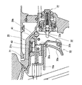
この手持ち工具10の工具本体11は、図1に示すように、打ち込み動作を行うための作動機構等を内蔵した出力部12と、出力部12に対して略直角に連設されたグリップ部13と、出力部12の軸方向先端側(止具の打ち込み方向)に一体的に固定されたノーズ部17と、ノーズ部17の後方に連設されたマガジン14と、を備える。また、出力部12とグリップ部13との境界部には、トリガ30を取り付けるためのトリガ取付部20が設けられている。
As shown in FIG. 1, a
トリガ30は、作業者に手動操作されて手持ち工具10を作動させるためのものであり、本実施形態においては打ち込み動作を実行させるための操作部である。このトリガ30は、グリップ部13を把持したときに人差し指で操作可能な位置に設けられている。後述するコンタクト部材18が被打ち込み材に押し付けられた状態でこのトリガ30が引き操作されると、出力部12に内蔵された作動機構が作動し、打ち込み動作が実行される。
The
このトリガ30は、図2及び図3に示すように、一端側に操作部30aを備え、他端側に被押圧部30bを備えている。操作部30aは、操作可能に工具本体11から露出しており、作業者が指をかけて操作するための部位である。また、被押圧部30bは、工具本体11の内部に挿入されており、操作部30aが操作されてトリガ30が揺動したときに、操作部30aとは逆方向へ揺動する部位である。この被押圧部30bは、後述する接触部材41によって後方へと付勢されており、これによりトリガ30が初期位置方向へと常に付勢されている。
As shown in FIGS. 2 and 3, the
また、このトリガ30の内側には、トリガバルブ22のバルブステム22aを作動させるためのコンタクトレバー32が揺動自在に取り付けられている。このコンタクトレバー32は、操作部30aの内部に形成された支軸32bによって揺動自在に支持されている。支軸32bに支持されていないコンタクトレバー32の先端32aは、後述するコンタクト連動部材18aに臨むように配置される。
Further, a
マガジン14は、射出口10aから射出される止具を収容するものであり、連結された止具を収容している。このマガジン14に収容された止具がノーズ部17の方向へ順次案内されて打ち込みに使用される。
The
ノーズ部17は、止具を射出する射出口10aを形成した部位であり、工具本体11の先端に突出して形成されている。このノーズ部17の内部には、止具を打ち出すためのドライバが摺動可能に収容されている。このノーズ部17の後方には止具供給機構が設けられている。この止具供給機構は、打込み動作に連動して送り動作を実行する。この送り動作によって、マガジン14に収容された止具がノーズ部17へと順番に送られる。
The
このノーズ部17には、コンタクト部材18が摺動可能に取り付けられている。コンタクト部材18は、ノーズ部17の先端から突出するように付勢されており、被打込み材に押し付け可能となっている。このコンタクト部材18は、被打ち込み材に押し付けたときにノーズ部17に対して反先端方向に摺動するようになっており、このようにコンタクト部材18が反先端方向に摺動することで打ち込み動作の安全機構が作動するようになっている。安全機構が作動することで、トリガ30の操作が有効となり、止具の打ち込みが可能となる。
A
具体的には、コンタクト部材18が反先端方向に摺動すると、図2〜4に示すコンタクト連動部材18aが後方(図2〜4における右方向)に連動して移動する。コンタクト連動部材18aが後方に移動すると、コンタクトレバー32の先端32aがトリガバルブ22の方向に押し付けられる。この状態でトリガ30が引き操作されると、コンタクトレバー32の中間部によってトリガバルブ22のバルブステム22aが押し込まれる。バルブステム22aが押し込まれることで、圧縮空気が出力部12のピストンに一気に流入して打ち込み動作が行われる。
Specifically, when the
ところで、上記したトリガ30は、図2及び図3に示すように、工具本体11に揺動可能に支持されている。詳しくは、図5(a)に示すように、工具本体11のトリガ取付部20には支持部材21が取り付けられており、この支持部材21に対してトリガ30が揺動可能に取り付けられている。トリガ30の取り付けは、工具本体11の側面から挿入したピンやボルト等の固定手段(図示せず)によって行われる。このため、この固定手段を取り外すことで、図4及び図5(b)に示すように、トリガ30を工具本体11から取り外すことができる。なお、本実施形態においては、トリガ30を着脱可能な支持部材21を工具本体11に内蔵させているが、支持部材21は必ずしも工具本体11に全体を覆われている必要はない。支持部材21が工具本体11に取り付けられた状態で、支持部材21に対してトリガ30が着脱可能であればよい。
By the way, the above-mentioned
支持部材21には、図5(b)に示すように、付勢部材40と接触部材41とが一体的に組み付けられている。言い換えると、付勢部材40及び接触部材41は、支持部材21が組み付けられた工具本体11に対して一体的に組み付けられている。このため、図4に示すように、トリガ30を工具本体11から取り外したとしても、付勢部材40及び接触部材41が工具本体11側に残るようになっている。
As shown in FIG. 5B, the supporting
付勢部材40は、トリガ30を反操作方向へと付勢するための付勢力を発生させるものである。本実施形態に係る付勢部材40は、後述する接触部材41を付勢する圧縮バネである。なお、付勢部材40は圧縮バネに限らず、所定の付勢力を発生させるものであればよい。例えば、引っ張りバネやその他の弾性体、エアで作動するもの、電気で作動するソレノイド等であってもよい。
The biasing
接触部材41は、付勢部材40の付勢力によって作動してトリガ30に作用するものであり、付勢部材40とトリガ30との間に配置される。この接触部材41は、付勢部材40を取り付けたバネ取付部41aと、両側に張り出して形成されたスライド突起41bと、後述する移動規制部21bに係合する係止部41cと、を備える。この接触部材41は、後述するスライド溝21aにスライド突起41bが係合することで、摺動可能に支持部材21に取り付けられる。また、バネ取付部41aが付勢部材40の付勢力を受けることで、トリガ30に係合する方向へと付勢されている。付勢部材40によって付勢された接触部材41は、係止部41cが移動規制部21bに当接する位置まで摺動可能となっている。トリガ30が引き操作された後に、この接触部材41がトリガ30の被押圧部30bを押圧することで、引き操作されたトリガ30が初期位置に復帰するようになっている。
The
なお、これらの付勢部材40及び接触部材41が組み付けられた支持部材21は、図6及び図7に示すように、接触部材41の移動を案内するスライド溝21aと、接触部材41の移動を規制する移動規制部21bと、付勢部材40の付勢力を受けるバネ受部21cと、を備える。
The
スライド溝21aは、接触部材41のスライド突起41bが挿入される溝部であり、接触部材41の摺動を案内するためのものである。接触部材41のスライド突起41bがこのスライド溝21aに係合することで、接触部材41がスライド溝21aの長手方向に沿って前後に摺動可能となっている。
The
移動規制部21bは、接触部材41の係止部41cに係合する壁部である。接触部材41の係止部41cがこの移動規制部21bに係合することで、接触部材41がスライド溝21aから脱落することが防止されるとともに、付勢部材40による付勢方向への、接触部材41の移動が規制されている。このように接触部材41の突出方向への移動が規制されることで、図4に示すように、工具本体11の内部に、接触部材41の先端側に空間Sが形成されている。この空間Sは、トリガ30の被押圧部30bを挿入するために使用される。空間Sの幅は、トリガ30の被押圧部30bの幅と同等か、トリガ30の被押圧部30bの幅よりもやや大きく形成されている。このため、空間Sに対してトリガ30の被押圧部30bを挿入するときに、被押圧部30bに付勢部材40の付勢力が働かないように形成されている。なお、空間Sの幅は、トリガ30の被押圧部30bの幅よりもやや小さく形成してもよい。このようにすれば、トリガ30の遊びをなくして、トリガ30のレスポンスを向上させることができる。
The
バネ受部21cは、付勢部材40を取り付けるための部位である。このバネ受部21cは、接触部材41のバネ取付部41aに対向して配置されている。このバネ受部21cと接触部材41のバネ取付部41aとの間に、圧縮された付勢部材40を取り付けることで、支持部材21と接触部材41とが互いに離反方向に付勢されるようになっている。
The
この支持部材21からトリガ30を取り外すと(すなわち工具本体11からトリガ30を取り外すと)、図4に示すように、工具本体11にはトリガ30を挿抜可能な開口部10bが開口する。このとき、接触部材41は、付勢部材40が付勢力を受けつつ、突出方向への移動が規制されている。接触部材41の先端は工具本体11の内壁に接触しておらず、接触部材41の先端と工具本体11の内壁との間には空間Sが形成されている。この空間Sは開口部10bを通して外部に臨むように配置されている。このため、取り外したトリガ30を再度取り付けるときには、トリガ30を開口部10bから直線的に挿入すれば、トリガ30の上端に突出形成された被押圧部30bが空間Sに挿入されるようになっている。
When the
以上説明したように、本実施形態によれば、付勢部材40及び接触部材41を工具本体11に一体的に組み付けたので、メンテナンス等のためにトリガ30を工具本体11から取り外したときに、バネなどの付勢部材40が脱落することがない。よって、付勢部材40の紛失や破損を防止することができる。また、取り外したトリガ30の組み付けも容易である。
As described above, according to the present embodiment, since the biasing
また、移動規制部21bによって接触部材41の移動が規制されることで、接触部材41の先端側に空間Sが形成されており、トリガ30は、空間Sに挿入される被押圧部30bを備える。このような構成によれば、空間Sに被押圧部30bを挿入するだけで、付勢部材40の負荷をほとんど受けることなくトリガ30を組み付けることができる。よって、トリガ30の組み付け性を向上させることができる。また、破損した付勢部材40の使用や付勢部材40の誤組付を防ぐことができるので、安全性を向上させることができる。
Further, since the
また、工具本体11は、トリガ30を挿抜可能な開口部10bを備え、トリガ30を取り外した状態で、空間Sが開口部10bを通して外部に臨むように配置されている。このような構成によれば、空間Sに向けてトリガ30を取り付ける際に、開口部10bから直線的にトリガ30を差し込んで組み付けることができる。よって、トリガ30の組み付け性が向上する。
Further, the tool
(第2の実施形態)
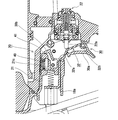
本発明の第2の実施形態について、図8〜10を参照しながら説明する。本実施形態の特徴は、付勢部材40及び接触部材41を工具本体11に一体的に組み付ける代わりに、付勢部材40及び接触部材41をトリガ30に一体的に組み付けた点にある。なお、本実施形態の基本的構成は第1の実施形態と相違しないため、重複する記載を避けて、相違する箇所のみを説明する。
(Second embodiment)
A second embodiment of the present invention will be described with reference to FIGS. The feature of this embodiment is that the biasing
本実施形態に係るトリガ30には、図8〜10に示すように、付勢部材40と接触部材41とが一体的に組み付けられている。このため、図10に示すように、トリガ30を工具本体11から取り外したときに、付勢部材40及び接触部材41がトリガ30と一体的に取り外されるようになっている。
As shown in FIGS. 8 to 10, a biasing
付勢部材40は、トリガ30を初期位置へと付勢するための付勢力を発生させるためのものである。本実施形態に係る付勢部材40は、後述する接触部材41を付勢する圧縮バネである。なお、付勢部材40は圧縮バネに限らず、所定の付勢力を発生させるものであればよい。例えば、引っ張りバネやその他の弾性体、エアで作動するもの、電気で作動するソレノイド等であってもよい。
The biasing
接触部材41は、付勢部材40の付勢力によって作動して工具本体11の被押圧部21dを押圧するものであり、トリガ30の内部に揺動可能に取り付けられている。この接触部材41は、トリガ30に対して揺動可能に取り付けるための揺動軸部41dと、工具本体11の被押圧部21dに対向配置される押圧部41eと、トリガ30の移動規制部30c(後述)に係合する係合部41fと、を備える。
The
これらの付勢部材40及び接触部材41が組み付けられたトリガ30は、図8〜10に示すように、接触部材41の移動を規制する移動規制部30cと、付勢部材40の付勢力を受けるバネ受部30dと、を備える。
As shown in FIGS. 8 to 10, the
移動規制部30cは、接触部材41の係合部41fに係合する突出部である。接触部材41の係合部41fがこの移動規制部30cに係合することで、付勢部材40による付勢方向への接触部材41の揺動が規制されている。このように接触部材41の揺動が規制されることで、図10に示すように、接触部材41がトリガ30から突出する方向に揺動しないように規制されている。接触部材41がトリガ30から突出していないので、後述する空間Sへ接触部材41を挿入し易くなっている。
The
バネ受部30dは、付勢部材40の一端を取り付けるための部位である。このバネ受部30dは、接触部材41の押圧部41eの裏側に対向して配置されている。接触部材41の押圧部41eの裏側に付勢部材40の他端が取り付けられるので、付勢部材40によって、バネ受部30dと押圧部41eとが互いに離反方向に付勢されるようになっている。
The
このトリガ30が引き操作されると、図9に示すように、接触部材41に対してトリガ30が揺動することで付勢部材40が圧縮される。その後、トリガ30が離されると、付勢部材40の復元力によって、接触部材41の押圧部41eが工具本体11の被押圧部21dを押圧し、その反力により引き操作されたトリガ30が初期位置に復帰する。
When the
なお、本実施形態に係る支持部材21は、図8〜10に示すように、工具本体11に取り付けられており、接触部材41によって押圧される被押圧部21dを備える。この被押圧部21dの先端側には、図10に示すように、トリガ30の上端及び接触部材41を挿入するための空間Sが形成されている。なお、本実施形態においては、トリガ30を着脱可能な支持部材21を工具本体11に内蔵させているが、支持部材21は必ずしも工具本体11に全体を覆われている必要はない。支持部材21が工具本体11に取り付けられた状態で、支持部材21に対してトリガ30が着脱可能であればよい。
The
空間Sの幅は、空間Sに挿入されるトリガ30の上端及び接触部材41の幅と同等か、空間Sに挿入されるトリガ30の上端及び接触部材41の幅よりもやや大きく形成されている。このため、空間Sに対してトリガ30を挿入するときに、付勢部材40の付勢力が働かないように形成されている。なお、空間Sの幅は、空間Sに挿入されるトリガ30の上端及び接触部材41の幅よりもやや小さく形成してもよい。このようにすれば、トリガ30の遊びをなくして、トリガ30のレスポンスを向上させることができる。
The width of the space S is equal to the width of the upper end of the
この支持部材21からトリガ30を取り外すと(すなわち工具本体11からトリガ30を取り外すと)、図10に示すように、工具本体11にはトリガ30を挿抜可能な開口部10bが開口する。また、上記した空間Sは、開口部10bを通して外部に臨むように配置されている。このため、取り外したトリガ30を再度取り付けるときには、トリガ30を開口部10bから直線的に挿入すれば、トリガ30の上端及び接触部材41が空間Sに挿入されるようになっている。
When the
以上説明したように、本実施形態によれば、付勢部材40及び接触部材41をトリガ30に一体的に組み付けたので、メンテナンス等のためにトリガ30を工具本体11から取り外したときに、バネなどの付勢部材40が脱落することがない。よって、付勢部材40の紛失や破損を防止することができる。また、取り外したトリガ30の組み付けも容易である。また、破損した付勢部材40の使用や付勢部材40の誤組付を防ぐことができるので、安全性を向上させることができる。
As described above, according to the present embodiment, since the biasing
また、工具本体11には接触部材41によって押圧される被押圧部21dの先端側に空間Sが形成されており、移動規制部30cによって接触部材41の移動が規制されることで接触部材41を空間Sに挿入可能となっている。このような構成によれば、空間Sに接触部材41を挿入する際に付勢部材40の負荷をほとんど受けることなくトリガ30を組み付けることができる。よって、トリガ30の組み付け性を向上させることができる。
Further, a space S is formed in the
また、工具本体11は、トリガ30を挿抜可能な開口部10bを備え、トリガ30を取り外した状態で、空間Sが開口部10bを通して外部に臨むように配置されている。このような構成によれば、空間Sに向けてトリガ30を取り付ける際に、開口部10bから直線的にトリガ30を差し込んで組み付けることができる。よって、トリガ30の組み付け性が向上する。
Further, the tool
なお、上記した第2の実施形態においては、トリガ30が支持部材21に対して着脱できるようにしたが、トリガ30を組み付けた支持部材21を工具本体11に対して着脱できるようにしてもよい。すなわち、予めトリガ30と付勢部材40と接触部材41とを支持部材21に組み付けたユニットを、工具本体11に着脱するようにしてもよい。このように構成した場合でも、付勢部材40及び接触部材41がトリガ30に一体的に組み付けられているので、付勢部材40及び接触部材41をトリガ30と一緒に着脱でき、上記した第2の実施形態と同様の効果を得ることができる。
In the above-described second embodiment, the
また、上記した第1の実施形態及び第2の実施形態においては、搖動するトリガ30について説明したが、直線的に摺動するトリガ30であっても同様の効果が得られることは言うまでもない。
Further, in the above-described first and second embodiments, the swinging
10 手持ち工具
10a 射出口
10b 開口部
11 工具本体
12 出力部
13 グリップ部
14 マガジン
17 ノーズ部
18 コンタクト部材
18a コンタクト連動部材
20 トリガ取付部
21 支持部材
21a スライド溝
21b 移動規制部
21c バネ受部
21d 被押圧部
22 トリガバルブ
22a バルブステム
30 トリガ
30a 操作部
30b 被押圧部
30c 移動規制部
30d バネ受部
32 コンタクトレバー
32a 先端
32b 支軸
40 付勢部材
41 接触部材
41a バネ取付部
41b スライド突起
41c 係止部
41d 揺動軸部
41e 押圧部
41f 係合部
S 空間
10 Hand-held
Claims (7)
前記トリガを移動可能に支持する支持部材と、
前記支持部材が組み付けられる工具本体と、
前記支持部材に設けられ、前記トリガを反操作方向へと付勢するための付勢力を発生させる付勢部材と、
前記支持部材に摺動可能に設けられ、前記付勢部材の付勢力によって前記トリガを反操作方向へ付勢するように作動する接触部材と、
を備え、
前記付勢部材及び前記接触部材は、前記支持部材とともに前記工具本体に一体的に組み付けられ、
前記トリガは、前記付勢部材及び前記接触部材を前記工具本体側に組み付けた状態で、前記支持部材に対して着脱可能であることを特徴とする、手持ち工具。 A hand-held tool with a trigger that is manually operated by an operator,
A support member for movably supporting the trigger,
A tool body to which the support member is assembled,
A biasing member that is provided on the support member and that generates a biasing force for biasing the trigger in a counter-operation direction;
A contact member that is slidably provided on the support member and that operates so as to bias the trigger in the counter-operation direction by the biasing force of the biasing member;
Equipped with
The urging member and the contact member are integrally assembled with the tool body together with the support member,
The hand-held tool, wherein the trigger is attachable/detachable to/from the support member in a state where the urging member and the contact member are assembled to the tool body side.
前記トリガを移動可能に支持する支持部材と、
前記支持部材が組み付けられる工具本体と、
前記支持部材に設けられ、前記トリガを反操作方向へと付勢するための付勢力を発生させる付勢部材と、
前記支持部材に摺動可能に設けられ、前記付勢部材の付勢力によって前記トリガを反操作方向へ付勢するように作動する接触部材と、
を備え、
前記付勢部材及び前記接触部材は、前記支持部材とともに前記工具本体に一体的に組み付けられ、
前記工具本体は、前記付勢部材による付勢方向への前記接触部材の移動を規制する移動規制部を備え、
前記移動規制部によって前記接触部材の移動が規制されることで、前記接触部材の先端側に空間が形成されており、
前記トリガは、前記空間に挿入されて前記接触部材に押圧される被押圧部を備えることを特徴とする、手持ち工具。 A hand-held tool with a trigger that is manually operated by an operator,
A support member for movably supporting the trigger,
A tool body to which the support member is assembled,
A biasing member that is provided on the support member and that generates a biasing force for biasing the trigger in a counter-operation direction;
A contact member that is slidably provided on the support member and that operates so as to bias the trigger in the counter-operation direction by the biasing force of the biasing member;
Equipped with
The urging member and the contact member are integrally assembled with the tool body together with the support member,
The tool body includes a movement restricting portion that restricts movement of the contact member in a biasing direction by the biasing member,
By restricting the movement of the contact member by the movement restricting portion, a space is formed on the tip side of the contact member,
The hand-held tool, wherein the trigger includes a pressed portion that is inserted into the space and pressed by the contact member.
前記トリガを取り外した状態で、前記空間が前記開口部を通して外部に臨むように配置されていることを特徴とする、請求項3記載の手持ち工具。 The tool body includes an opening through which the trigger can be inserted and removed,
The handheld tool according to claim 3, wherein the space is arranged so as to face the outside through the opening with the trigger removed.
前記トリガを移動可能に支持する工具本体と、
前記トリガに設けられた付勢部材と、
前記トリガに設けられ、前記付勢部材の付勢力によって作動して前記工具本体を押圧する接触部材と、
を備え、
前記付勢部材及び前記接触部材を、前記トリガに一体的に組み付け、
前記接触部材が前記工具本体を押圧することによって、前記トリガが反操作方向へ付勢されることを特徴とする、手持ち工具。 A hand-held tool with a trigger that is manually operated by an operator,
A tool body for movably supporting the trigger,
A biasing member provided on the trigger;
A contact member provided on the trigger, which operates by the urging force of the urging member to press the tool body;
Equipped with
The biasing member and the contact member are integrally assembled to the trigger,
The hand-held tool, wherein the contact member presses the tool body to urge the trigger in a counter-operation direction.
前記トリガは、前記付勢部材による付勢方向への前記接触部材の移動を規制する移動規制部を備え、
前記移動規制部によって前記接触部材の移動が規制されることで、前記接触部材を前記空間に挿入可能となっていることを特徴とする、請求項5記載の手持ち工具。 In the tool body, a space is formed on the tip side of the pressed portion pressed by the contact member,
The trigger includes a movement restricting portion that restricts movement of the contact member in a biasing direction by the biasing member,
The handheld tool according to claim 5, wherein the contact member can be inserted into the space by restricting the movement of the contact member by the movement restricting portion.
前記トリガを取り外した状態で、前記空間が前記開口部を通して外部に臨むように配置されていることを特徴とする、請求項6記載の手持ち工具。 The tool body includes an opening through which the trigger can be inserted and removed,
The handheld tool according to claim 6, wherein the space is arranged so as to face the outside through the opening when the trigger is removed.
Priority Applications (5)
| Application Number | Priority Date | Filing Date | Title |
|---|---|---|---|
| JP2016065609A JP6720634B2 (en) | 2016-03-29 | 2016-03-29 | Hand tools |
| US15/461,804 US10668609B2 (en) | 2016-03-29 | 2017-03-17 | Hand tool |
| EP17000457.6A EP3246131B1 (en) | 2016-03-29 | 2017-03-20 | Hand tool |
| DK17000457.6T DK3246131T3 (en) | 2016-03-29 | 2017-03-20 | Hand tools |
| TW106109110A TWI740913B (en) | 2016-03-29 | 2017-03-20 | Hand tool |
Applications Claiming Priority (1)
| Application Number | Priority Date | Filing Date | Title |
|---|---|---|---|
| JP2016065609A JP6720634B2 (en) | 2016-03-29 | 2016-03-29 | Hand tools |
Publications (2)
| Publication Number | Publication Date |
|---|---|
| JP2017177259A JP2017177259A (en) | 2017-10-05 |
| JP6720634B2 true JP6720634B2 (en) | 2020-07-08 |
Family
ID=58401325
Family Applications (1)
| Application Number | Title | Priority Date | Filing Date |
|---|---|---|---|
| JP2016065609A Active JP6720634B2 (en) | 2016-03-29 | 2016-03-29 | Hand tools |
Country Status (5)
| Country | Link |
|---|---|
| US (1) | US10668609B2 (en) |
| EP (1) | EP3246131B1 (en) |
| JP (1) | JP6720634B2 (en) |
| DK (1) | DK3246131T3 (en) |
| TW (1) | TWI740913B (en) |
Families Citing this family (1)
| Publication number | Priority date | Publication date | Assignee | Title |
|---|---|---|---|---|
| JP6720634B2 (en) * | 2016-03-29 | 2020-07-08 | マックス株式会社 | Hand tools |
Family Cites Families (42)
| Publication number | Priority date | Publication date | Assignee | Title |
|---|---|---|---|---|
| FR75887E (en) * | 1959-06-12 | 1961-08-18 | Prospection & Inventions | Improvements to nail guns for driving tips and other similar items, such as dowels, dowels, etc., into hard and compact materials and resulting gun |
| US3155980A (en) * | 1962-01-19 | 1964-11-10 | Star Expansion Ind Corp | Powder actuated tool |
| US4260092A (en) * | 1979-07-02 | 1981-04-07 | Duo-Fast Corporation | Safety assembly for a tool for driving fasteners |
| DE3337278A1 (en) | 1983-10-13 | 1985-04-25 | Metabowerke GmbH & Co, 7440 Nürtingen | Driving-in machine |
| US5191861A (en) * | 1991-07-12 | 1993-03-09 | Stanley-Bostitch, Inc. | Internal combustion actuated portable tool |
| US5687897A (en) * | 1995-07-28 | 1997-11-18 | Campbell Hausfeld/Scott Fetzer Company | Dual mode pneumatic tool |
| JPH10146775A (en) | 1996-11-15 | 1998-06-02 | Max Co Ltd | Trigger lever installation mechanism in nailing machine |
| US5797533A (en) * | 1997-01-21 | 1998-08-25 | Lee; Yun-Chung | Stapler safety trigger |
| DE29816673U1 (en) | 1998-09-17 | 1999-10-21 | Atlas Copco Electric Tools | Hand-held tool |
| US6964553B2 (en) * | 2003-05-23 | 2005-11-15 | Illinois Tool Works Inc. | Port for a fan chamber |
| US7931181B2 (en) * | 2005-02-18 | 2011-04-26 | Hitachi Koki Co., Ltd. | Combustion-type power tool with trigger control arrangements |
| JP4586564B2 (en) * | 2005-02-18 | 2010-11-24 | 日立工機株式会社 | Combustion nailer |
| US7152773B2 (en) * | 2005-03-23 | 2006-12-26 | Rexon Industrial Corp., Ltd. | Trigger selector for a nail gun |
| JP4879570B2 (en) * | 2005-12-01 | 2012-02-22 | 日本電産テクノモータホールディングス株式会社 | Trigger switch for electric tools |
| US20070194076A1 (en) | 2006-02-23 | 2007-08-23 | Samson Power Tool Co., Ltd. | Safety device for staplers |
| NZ572043A (en) * | 2006-04-20 | 2010-05-28 | Illinois Tool Works | Fastener-driving tool having trigger control mechanism for alternatively permitting bump firing and sequential firing modes of operation |
| JP4752751B2 (en) * | 2006-12-18 | 2011-08-17 | 日立工機株式会社 | Driving machine |
| JP4650431B2 (en) * | 2007-01-19 | 2011-03-16 | 日立工機株式会社 | Combustion type driving tool |
| JP5429512B2 (en) * | 2008-01-31 | 2014-02-26 | 日立工機株式会社 | Driving machine |
| TW200942375A (en) * | 2008-04-07 | 2009-10-16 | Basso Ind Corp | Nail gun with safety device |
| TW201008717A (en) * | 2008-08-18 | 2010-03-01 | Basso Ind Corp | LPG-powered nail gun with safe firing mechanism |
| TWI404603B (en) * | 2009-04-03 | 2013-08-11 | Basso Ind Corp | Safety device for preventing a tool misfire |
| US8960516B2 (en) * | 2009-09-30 | 2015-02-24 | Hitachi Koki Co., Ltd. | Fastener driving tool |
| JP5448943B2 (en) * | 2010-03-10 | 2014-03-19 | 佐鳥エス・テック株式会社 | Trigger switch |
| JP2011183528A (en) | 2010-03-10 | 2011-09-22 | Mitsubishi Electric Corp | Automatic programming device and operation program thereof |
| JP5360692B2 (en) * | 2010-03-31 | 2013-12-04 | 日立工機株式会社 | Combustion type driving machine |
| US9339925B2 (en) * | 2010-07-01 | 2016-05-17 | Stanley Fastening Systems, L.P. | Fastener driving device with dust blower |
| TWI392566B (en) * | 2010-08-10 | 2013-04-11 | Basso Ind Corp | Vessel nail gun against the air firing device |
| US8292143B2 (en) * | 2010-10-12 | 2012-10-23 | Stanley Fastening Systems, L.P. | Dry fire lockout with bypass for fastener driving device |
| DE102011076158B4 (en) * | 2011-05-20 | 2013-01-03 | Hilti Aktiengesellschaft | Bolt apparatus and method for operating a bolt gun |
| TWI574796B (en) * | 2011-08-23 | 2017-03-21 | 日立工機股份有限公司 | Fastening tool |
| US9604355B2 (en) * | 2011-09-30 | 2017-03-28 | Textron Innovations Inc. | Handle for a hydraulically driven tool with heat transmission reducing properties |
| WO2013177423A2 (en) | 2012-05-23 | 2013-11-28 | Stryker Corporation | Powered surgical tool assembly including a tool unit and a separate battery and control module that energizes and controls the tool unit |
| US9486907B2 (en) * | 2013-01-15 | 2016-11-08 | Illinois Tool Works Inc. | Reversion trigger for combustion-powered fastener-driving tool |
| TWI451947B (en) * | 2013-06-18 | 2014-09-11 | Basso Ind Corp | Gas guns for gas cylinders |
| TWI671169B (en) * | 2014-06-30 | 2019-09-11 | 日商工機控股股份有限公司 | Driving machine |
| US9862083B2 (en) * | 2014-08-28 | 2018-01-09 | Power Tech Staple and Nail, Inc. | Vacuum piston retention for a combustion driven fastener hand tool |
| JP6408944B2 (en) * | 2015-03-24 | 2018-10-17 | 株式会社マキタ | Driving tool |
| FR3046741B1 (en) * | 2016-01-20 | 2018-01-05 | Illinois Tool Works Inc | GAS FASTENING TOOL |
| JP6720634B2 (en) * | 2016-03-29 | 2020-07-08 | マックス株式会社 | Hand tools |
| TWI600510B (en) * | 2016-08-22 | 2017-10-01 | Trigger mechanism to switch firing mode pneumatic tools | |
| US11141845B2 (en) * | 2017-02-02 | 2021-10-12 | Illinois Tool Works Inc. | Combustion-powered tool with sleeve-retaining lockout device |
-
2016
- 2016-03-29 JP JP2016065609A patent/JP6720634B2/en active Active
-
2017
- 2017-03-17 US US15/461,804 patent/US10668609B2/en active Active
- 2017-03-20 DK DK17000457.6T patent/DK3246131T3/en active
- 2017-03-20 TW TW106109110A patent/TWI740913B/en active
- 2017-03-20 EP EP17000457.6A patent/EP3246131B1/en active Active
Also Published As
| Publication number | Publication date |
|---|---|
| JP2017177259A (en) | 2017-10-05 |
| EP3246131A1 (en) | 2017-11-22 |
| TW201801865A (en) | 2018-01-16 |
| DK3246131T3 (en) | 2019-08-19 |
| US10668609B2 (en) | 2020-06-02 |
| US20170282340A1 (en) | 2017-10-05 |
| TWI740913B (en) | 2021-10-01 |
| EP3246131B1 (en) | 2019-06-26 |
Similar Documents
| Publication | Publication Date | Title |
|---|---|---|
| US8336748B2 (en) | Fastener driver with driver assembly blocking member | |
| JP4430730B2 (en) | Power tool | |
| US6866177B1 (en) | Depth control device for a fastener driving tool | |
| NO324987B1 (en) | Device for adjusting the driving depth of a fastening drive tool with interchangeable contact element and method for changing contact elements | |
| JP2008279558A (en) | Driving machine | |
| US8042718B2 (en) | Fuel cell actuation mechanism for combustion-powered tool | |
| US7721928B2 (en) | Nail-driving device with safety unit | |
| KR20060107470A (en) | Improved nailer with a safety device | |
| US11407094B2 (en) | Fastening tool having a low nail, lockout mechanism | |
| JP6720634B2 (en) | Hand tools | |
| JP2019014010A (en) | Placing tool | |
| JP5402868B2 (en) | Driving tool | |
| JP4525585B2 (en) | Nailing mechanism of floor nailing machine | |
| JP6870208B2 (en) | Driving tool | |
| JP7118873B2 (en) | driving tool | |
| JP7107650B2 (en) | driving tool | |
| JP4770278B2 (en) | Contact top storage structure for driving tools | |
| JP4534623B2 (en) | Nose top guide device for fastener-driven tools | |
| JP6772490B2 (en) | Driving tool | |
| JP6848238B2 (en) | Driving tool | |
| JP2005161496A (en) | Contact nose connecting mechanism of nailing machine | |
| JP2021003803A (en) | Driving tool | |
| JP5138415B2 (en) | Driving tool | |
| JP2022092819A (en) | Driving tool | |
| JP3952887B2 (en) | Contact member guide mechanism in nailing machine |
Legal Events
| Date | Code | Title | Description |
|---|---|---|---|
| A621 | Written request for application examination |
Free format text: JAPANESE INTERMEDIATE CODE: A621 Effective date: 20181227 |
|
| A131 | Notification of reasons for refusal |
Free format text: JAPANESE INTERMEDIATE CODE: A131 Effective date: 20190827 |
|
| A521 | Written amendment |
Free format text: JAPANESE INTERMEDIATE CODE: A523 Effective date: 20191025 |
|
| A131 | Notification of reasons for refusal |
Free format text: JAPANESE INTERMEDIATE CODE: A131 Effective date: 20191204 |
|
| A521 | Written amendment |
Free format text: JAPANESE INTERMEDIATE CODE: A523 Effective date: 20200127 |
|
| A131 | Notification of reasons for refusal |
Free format text: JAPANESE INTERMEDIATE CODE: A131 Effective date: 20200225 |
|
| A521 | Written amendment |
Free format text: JAPANESE INTERMEDIATE CODE: A523 Effective date: 20200225 |
|
| TRDD | Decision of grant or rejection written | ||
| A01 | Written decision to grant a patent or to grant a registration (utility model) |
Free format text: JAPANESE INTERMEDIATE CODE: A01 Effective date: 20200519 |
|
| A61 | First payment of annual fees (during grant procedure) |
Free format text: JAPANESE INTERMEDIATE CODE: A61 Effective date: 20200601 |
|
| R150 | Certificate of patent or registration of utility model |
Ref document number: 6720634 Country of ref document: JP Free format text: JAPANESE INTERMEDIATE CODE: R150 |