JP4534623B2 - Nose top guide device for fastener-driven tools - Google Patents
Nose top guide device for fastener-driven tools Download PDFInfo
- Publication number
- JP4534623B2 JP4534623B2 JP2004185425A JP2004185425A JP4534623B2 JP 4534623 B2 JP4534623 B2 JP 4534623B2 JP 2004185425 A JP2004185425 A JP 2004185425A JP 2004185425 A JP2004185425 A JP 2004185425A JP 4534623 B2 JP4534623 B2 JP 4534623B2
- Authority
- JP
- Japan
- Prior art keywords
- nose
- injection port
- fastener
- guide
- nose top
- Prior art date
- Legal status (The legal status is an assumption and is not a legal conclusion. Google has not performed a legal analysis and makes no representation as to the accuracy of the status listed.)
- Active
Links
Images


Description
本発明は、互いに連結されたネジや釘等のファスナーをノーズ部に形成された中空の射出口内に供給し、該ファスナーを射出口内で動力的に推進駆動されるドライバによって射出口の先端方向へ打ち出すようにしたファスナー駆動工具に関し、特に、射出口から打ち出されたファスナーを被打込材へ向けて誘導させるため前記ノーズ部に沿って摺動可能でかつ射出口の先端方向に突出して配置したノーズトップをノーズ部の射出口に沿って摺動させるためのファスナー駆動工具のノーズトップガイド装置に関する。 According to the present invention, fasteners such as screws and nails connected to each other are supplied into a hollow injection port formed in a nose portion, and the fastener is driven in the injection port in the direction of the distal end of the injection port by a driving force. With regard to the fastener driving tool designed to be punched out, in particular, it is slidable along the nose portion and arranged to protrude in the tip direction of the injection port in order to guide the fastener driven out from the injection port toward the material to be driven. The present invention relates to a nose top guide device for a fastener driving tool for sliding a nose top along an injection port of a nose portion.
例えば、圧縮空気を動力源とするネジ打機や釘打機等のファスナー駆動工具においては、ファスナー駆動工具のボディを形成しているハウジング内にネジや釘等のファスナーと係合されるドライバを駆動するためピストンやシリンダ等から構成されている駆動機構が収容されている。前記ハウジングの下方には前記ファスナーを被打込材へ向けて打ち出し案内する中空状の射出口を形成しているノーズ部が取り付けられ、前記ピストンの下面側に一体に結合されたドライバが前記ノーズ部のファスナー射出口内に摺動自在に案内されている。ノーズ部には間隔を隔てて対向した一対のガイド壁によって形成されている供給ガイドを介して多数の連結されたファスナーを収容するマガジンが連結されており、ノーズ部に形成されているファスナー供給機構によりマガジン内のファスナーが前記供給ガイドを経由してファスナー射出口内へ順次供給され、前記駆動機構により駆動される前記ドライバによって射出口内に供給されたファスナーが射出口内から被打込材面に向けて打ち出されるようにされている。 For example, in a fastener driving tool such as a screw driving machine or a nail driving machine using compressed air as a power source, a screwdriver or a screwed nail screwdriver is engaged in a housing forming the body of the fastener driving tool. In order to drive, the drive mechanism comprised from a piston, a cylinder, etc. is accommodated. A nose portion that forms a hollow injection port for driving and guiding the fastener toward the driven material is attached below the housing, and a driver integrally coupled to the lower surface side of the piston is connected to the nose. It is slidably guided in the fastener outlet of the part. The nose portion is connected magazine for accommodating a plurality of connected fastener through the supply guide formed by a pair of guide walls opposed at a distance, the fastener supply mechanism formed in the nose portion Thus, the fasteners in the magazine are sequentially supplied into the fastener injection port via the supply guide, and the fasteners supplied into the injection port by the driver driven by the drive mechanism are directed from the injection port toward the surface to be driven. It is designed to be launched.
一般的なファスナー駆動工具では、ファスナー駆動工具を起動させた際に反動によってファスナー駆動工具が被打込材面から離れてしまった場合でも、射出口の先端から被打込材へ向けて打ち出されるファスナーを確実に被打込材面へ誘導させるために、ノーズ部に沿ってファスナーの打ち出し方向に摺動自在に設けられるとともにノーズ部の射出口の前方に突出して配置されたノーズトップを備えている。このノーズトップは通常時にノーズ部の先端方向に突出するようにバネ付勢されて配置されており、ファスナー駆動工具の射出口先端を被打込材面の打ち込み箇所に位置決めする際にノーズ部に沿って摺動操作されるようにされている。更に、ファスナー駆動工具のハウジングに一体に形成されているグリップ部の基部には、ファスナー駆動工具を起動するためのトリガ機構が形成されており、グリップを把持している作業者によって操作されるトリガレバーと前記ノーズトップの摺動操作によりこのトリガ機構を操作することでファスナー駆動工具を起動させるようにしている。 In a general fastener driving tool, even when the fastener driving tool is separated from the surface of the workpiece by reaction when the fastener driving tool is activated, the tool is driven out from the tip of the injection port toward the workpiece. In order to ensure that the fastener is guided to the surface to be driven, a nose top is provided that is slidable along the nose portion in the direction in which the fastener is ejected and is disposed so as to protrude forward of the injection port of the nose portion. Yes. This nose top is normally spring-biased so as to protrude in the direction of the tip of the nose part, and is positioned at the nose part when positioning the tip of the injection port of the fastener driving tool at the place to be driven on the surface of the workpiece. It is designed to be slid along. Furthermore, a trigger mechanism for starting the fastener driving tool is formed at the base of the grip portion formed integrally with the fastener driving tool housing, and the trigger is operated by an operator holding the grip. The fastener driving tool is activated by operating the trigger mechanism by sliding the lever and the nose top.
上記従来のノーズトップは中心に開口が形成されたほぼ円筒状に形成されており、この中心開口内に射出口を形成しているノーズ部の先端外周部を収容して、ノーズ部の外周面に沿って摺動できるように支持され、ノーズ部に対して射出口に沿って摺動可能にガイドされている。更にこのノーズトップの一方の側面には先端が上方へ向けて延びたロッドが取り付けられており、このロッドの上端部がノーズ部に形成されているコンタクト弁のロッドガイド孔内に収容されて、前記ノーズトップがこのロッドガイド孔によって摺動案内されるようにしている。ノーズトップが操作されることによりロッドを介してコンタクト弁が操作されることによって前記トリガ機構が作動して工具を起動させるようにしている。
上記従来のノーズトップは、ノーズトップの中心に形成されている開口内にノーズ部先端部を収容するとともに、上端部がロッドガイド穴に挿入案内されているロッドをノーズトップの一方の側面に連結することによってノーズトップを摺動案内させるようにしているが、一般的に、石膏ボードのネジ止め施工等に使用するネジ締め機等のファスナー駆動工具では、ネジ締め施工時等に生じる石膏ボードの粉がノーズ部の外周面とノーズトップの開口の内周面との間に進入してかじったりしてノーズトップの摺動作動を阻害してしまうことがあるため、ノーズ部外周面とノーズトップの開口の内周面との間の隙間を大きく設定しており、このためノーズトップにガタが生じて操作性が不安定になってしまうという問題が発生する。 The above-mentioned conventional nose top accommodates the tip of the nose portion in the opening formed at the center of the nose top and connects the rod whose upper end portion is guided by insertion into the rod guide hole to one side surface of the nose top. In this way, the nose top is slid and guided. However, in general, a fastener driving tool such as a screw tightening machine used for screwing a gypsum board, etc. Since the powder may enter between the outer peripheral surface of the nose part and the inner peripheral surface of the opening of the nose top and galvanize, the sliding operation of the nose top may be hindered, so the outer peripheral surface of the nose part and the nose top The gap between the opening and the inner peripheral surface is set large, which causes a problem that the nose top becomes loose and the operability becomes unstable.
また、一般的にノーズ部の前方側や両側にノーズトップを摺動案内させるためのガイドロッドを形成するとノーズ部の外周側のボリュウムが大きくなり、例えば、壁際等の隅部へのファスナー打ち込み作業時にこの部分が壁に当接してしまい、ファスナー駆動工具を大きく傾けないと射出口の先端を隅部の近くに位置決めすることができなる等の操作性を損ってしまうという問題が発生する。 In general, if a guide rod for sliding and guiding the nose top is formed on the front side or both sides of the nose part, the volume on the outer peripheral side of the nose part becomes large. Occasionally, this portion comes into contact with the wall, and there arises a problem that the operability is deteriorated such that the tip of the injection port cannot be positioned near the corner unless the fastener driving tool is largely inclined.
本発明は、上記従来技術での問題点を解決して、ファスナーを被打込材へ誘導案内するノーズトップをノーズ部に対して安定して摺動案内させるようにしたノーズトップガイド装置を提供することを課題とする。 The present invention provides a nose top guide device that solves the above-described problems in the prior art and stably slides and guides the nose top that guides and guides the fastener to the workpiece. The task is to do.
上記課題を解決するため本発明のファスナー駆動工具のノーズトップガイド装置は、ネジや釘等のファスナーを配置させる中空状の射出口を形成しているノーズ部と、ファスナーを前記ノーズ部の射出口内へ誘導案内する一対のガイド壁によって構成されるとともに一方のガイド壁がノーズ部の側面に沿って配置された枢支軸によって回動可能に支持されたドア部材により形成されているファスナーの供給ガイドと、圧縮空気等の動力により推進駆動されて前記射出口内に配置されたファスナーを射出口の先端方向へ打ち出すようにしたドライバと、前記射出口から打ち出されたファスナーを被打込材へ向けて誘導案内するように前記ノーズ部の射出口の先端にノーズ部に沿って摺動自在に保持させたノーズトップとを設けたファスナー駆動工具において、前記ノーズトップの中心に形成した開口内に前記ノーズ部を摺動自在に遊嵌させるとともに、該ノーズトップをノーズ部の一方の側面に沿って摺動自在に配置されているコンタクトアームと連結して該コンタクトアームによってノーズトップの一方の側面を案内させ、更に、前記ドア部材を枢動自在に支持している枢支軸を、前記射出口と平行に形成するとともに、該枢支軸によって前記ノーズトップの他方の側面を摺動可能に支持させたことを特徴とする。 In order to solve the above-mentioned problems, a nose top guide device for a fastener driving tool according to the present invention includes a nose part forming a hollow injection port for placing a fastener such as a screw or a nail, and a fastener in the injection port of the nose part. Fastener supply guide which is formed by a door member which is constituted by a pair of guide walls which guide and guide to the side and one guide wall is rotatably supported by a pivot shaft which is arranged along the side surface of the nose portion A driver that is propelled and driven by power such as compressed air to drive the fastener disposed in the injection port toward the tip of the injection port, and the fastener that is driven out of the injection port toward the material to be driven Fastener drive provided with a nose top that is slidably held along the nose portion at the tip of the injection port of the nose portion so as to guide and guide A contact arm in which the nose portion is slidably fitted in an opening formed at the center of the nose top and the nose top is slidably disposed along one side surface of the nose portion. And a contact shaft that guides one side surface of the nose top, and further, a pivot shaft that pivotally supports the door member is formed in parallel with the injection port, and The other side surface of the nose top is slidably supported by a shaft.
本発明によれば、ノーズトップの中心に形成した開口内に前記ノーズ部を摺動自在に遊嵌させるとともに、該ノーズトップをノーズ部の一方の側面に沿って摺動自在に配置されているコンタクトアームと連結して該コンタクトアームによってノーズトップの一方の側面を案内させ、更に、前記ドア部材を枢動自在に支持している枢支軸を、前記射出口と平行に形成するとともに、該枢支軸によって前記ノーズトップの他方の側面を摺動可能に支持させているので、ノーズトップが、コンタクトアームとドア部材を枢支している枢支軸とによってノーズ部の射出口を挟んだ両側面で摺動案内されるので、ノーズ部とノーズトップの中心に形成した開口とノーズ部との間に大きな隙間を形成しても、ノーズトップのがたつきが少なくなって操作感が改善される。また、ファスナー駆動工具に形成される枢支軸を利用するので部品点数を増やすことなくノーズトップの摺動操作性の改善が行える。さらに、枢支軸はノーズ部の側面に形成されているので、ノーズ部の前面側のボリウムが大きくなることが無く隅打ち性能が低下することがない。 According to the present invention, the nose portion is slidably fitted in an opening formed at the center of the nose top, and the nose top is slidably disposed along one side surface of the nose portion. A contact arm is connected to guide one side surface of the nose top by the contact arm, and a pivot shaft that pivotally supports the door member is formed in parallel with the injection port, and Since the other side surface of the nose top is slidably supported by the pivot shaft, the nose top sandwiches the injection port of the nose portion by the pivot shaft pivotally supporting the contact arm and the door member. Because it is slidably guided on both sides, even if a large gap is formed between the nose and the opening formed at the center of the nose top, the backlash of the nose top is reduced and operational feeling is reduced. It is improved. Further, since the pivot shaft formed on the fastener driving tool is used, the sliding operability of the nose top can be improved without increasing the number of parts. Furthermore, since the pivot shaft is formed on the side surface of the nose portion, the volume on the front side of the nose portion does not increase and the cornering performance does not deteriorate.
本発明は、ファスナーを被打込材へ誘導案内するノーズトップをノーズ部に対して安定して摺動案内させるという目的を、ノーズトップの中心に形成した開口内に前記ノーズ部を摺動自在に遊嵌させるとともに、該ノーズトップをノーズ部の一方の側面に沿って摺動自在に配置されているコンタクトアームと連結して該コンタクトアームによってノーズトップの一方の側面を案内させ、更に、前記ドア部材を枢動自在に支持している枢支軸を、前記射出口と平行にノーズ部の先端方向に延長形成するとともに、該枢支軸によって前記ノーズトップの他方の側面を摺動可能に支持させることによって実現したもので、より具体的な実施例を以下に説明する。 The purpose of the present invention is to slidably slide the nose part into an opening formed at the center of the nose top, with the purpose of stably sliding and guiding the nose top for guiding and guiding the fastener to the workpiece. The nose top is connected to a contact arm that is slidably disposed along one side surface of the nose portion, and the one side surface of the nose top is guided by the contact arm. A pivot shaft that pivotally supports the door member is extended in the tip direction of the nose portion in parallel with the injection port, and the other side surface of the nose top can be slid by the pivot shaft. More specific embodiments will be described below, which are realized by supporting them.
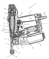
以下、図面に示す実施例に基づいて本発明の実施の形態を説明する。図1及び図2は本発明のノーズトップガイド装置を実施したファスナー駆動工具の一例としての圧縮空気によって駆動するようにしたネジ打機を示すものであり、該ネジ打機1はグリップ部3が一体に形成されたハウジング2の下方にネジを被打込材に向けて案内する中空状の射出口5を形成しているノーズ部4が取り付けられている。該ノーズ部4には多数の連結されたネジを収容するマガジン6が連結されており、前記射出口5とマガジン6との間に形成された供給ガイド7に形成されている供給機構8によってマガジン6内の連結ネジが供給ガイド7に沿ってノーズ部4の射出口5内へ順次供給されるようにされている。
Hereinafter, embodiments of the present invention will be described based on examples shown in the drawings. 1 and 2 show a screw driving machine driven by compressed air as an example of a fastener driving tool in which the nose top guide device of the present invention is implemented. The
前記ハウジング2内にはピストン9を摺動自在に収容しているシリンダ10が配置されており、該シリンダ10内に収容されているピストン9の下面側にはネジの頭部に形成されたプラス溝と係合してネジを回転駆動するドライバビット11が保持されている。該ドライバビット11が前記ノーズ部4に形成された射出口5内に摺動可能に案内されており、前記シリンダ10内に圧縮空気が導入されることによってこの圧縮空気の圧力により前記ピストン9がシリンダ10の上死点位置からハウジング2の下部に配置されているバンパ30と当接する下死点位置に向けて作動されることによって、このピストン9の作動によって前記ドライバビット11が射出口5内で推進作動されて、ドライバビット11の先端が射出口5内に供給されているネジの頭部と係合して該ネジを射出口5の先端方向へ推進させる。
A
前記マガジン6の上方には圧縮空気により駆動されるエアモータ12が配置されており、このエアモータ12の回転力が複数のギヤから構成されている減速機構13を介して前記ピストン9の下面に保持されているドライバビット11に伝達されて、射出口5内を推進作動されるドライバビット11を回転駆動させるようにしている。前記ノーズ部4の先端には前記射出口5からドライバビット11によって打ち出されるネジを被打込材の表面まで誘導案内させるノーズトップ14が設けられている。このノーズトップ14には、ノーズ部4の射出口5と同心状の開口15が形成されており、この開口15内に上部がノーズトップ14に対して回動自在に枢着支持された一対のガイド部材16が対向して配置されており、ノーズ部4の射出口5から打ち出されたネジをこの一対のガイド部材16間で挟持してネジを被打込材の表面に対して垂直な姿勢となるように誘導案内するようにしている。
An
前記ノーズトップ14に形成された開口15の上部に前記ノーズ部の下端部が遊嵌されており、これによってノーズトップ14がノーズ部4に対して射出口5に沿って摺動可能に保持されており、ネジ打機1のノーズ部4を被打込材の打ち込み位置へ位置決めすることによってノーズトップ14が被打込材と当接して摺動操作されるようにノーズ部4の射出口5の先端より更に先端方向へ突出して配置されている。
The lower end portion of the nose portion is loosely fitted on the upper portion of the
ハウジング2と一体に形成されているグリップ部3の内部には中空状のエアチャンバ17が形成されており、グリップ部3の後端に取り付けられているエアプラグ18を介して圧縮空気源から供給される圧縮空気を貯留するようにしている。このエアチャンバ17内の圧縮空気が前記シリンダ10の上部に形成されているメインバルブ19を介してシリンダ10内に供給されることによりピストン9を介して前記ドライバ11を駆動させるようにしている。また、前記メインバルブ19を経由してシリンダ10内に導入される圧縮空気の一部は同時に前記エアモータ12へも供給されてエアモータ12を駆動させて前記ドライバ11を回転駆動させるようにしている。
A
前記グリップ部3の基部には前記メインバルブ19を作動させるためのトリガバルブ20と、このトリガバルブ20を操作してネジ打機1を起動させるためのトリガ機構21が形成されている。トリガ機構21は、グリップ3部を把持している手の指によって操作されるトリガレバー22と、上端がトリガレバー22の基部に配置されるとともに下端が前記ノーズトップ14に連結されているコンタクトアーム23とによって構成されており、ノーズトップ14が被打込材の表面に押し当てられて摺動操作されることと、グリップ部3の基部に配置されているトリガレバー22が作業者の指によって操作されることによって前記トリガバルブ20を作動させてネジ打機1を起動するようにしている。そして、前記ノーズトップ14はノーズトップ14の中心に形成されている開口15内にノーズ部4を遊嵌するとともに、ノーズ部4の一方の側面に沿って作動可能に支持されているコンタクトアーム23の下端と連結されることによってノーズ部4に沿って摺動可能に保持されている。
A trigger valve 20 for operating the
図1及び図3に示すように、上記ネジ打機1は、マガジン6から射出口5内へネジを供給案内するための前記供給ガイド7を形成している一方のガイド壁が、ノーズ部4の側面で射出口5の軸線と平行に配置されている枢支軸24によって開閉可能に枢支されているドア部材25によって構成されており、マガジン6内へネジを装填したときにこのドア部材25を開放して、連結ネジの先頭部分のネジを射出口5内及び供給機構8にセットできるようにしている。この枢支軸24はノーズ部4の側面に突出させて一体に形成されている一対のヒンジ片26にノーズ部4の射出口5と平行となるように貫挿されており、該枢支軸24の上端をノーズ部4と当接させるとともに枢支軸24の上端部に装着した止めリング27によってノーズ部4に保持されている。そして、前記一対のヒンジ片26の間に配置されている前記ドア部材25を枢支軸24が貫挿されることによってドア部材25が回動可能に支持されている。
As shown in FIGS. 1 and 3, in the
図3及び図4に示すように、前記ドア部材25を枢支している枢支軸24の下端部がヒンジ片26より更にノーズ部4の側面に沿って先端方向へ延長して形成されている。また、前記ノーズトップ14のコンタクトアーム23が連結されていない他方側の側面にはガイド片28が一体に形成されており、このガイド片28に形成されているガイド孔29内に前記枢支軸24の下端部を収容することによって、ノーズトップ14の他方側の側面を枢支軸24によって摺動案内させるようにしている。
As shown in FIGS. 3 and 4, the lower end portion of the
ネジ打機1を操作する以前では、図4に示すように、ノーズトップ14は前方へ向けてバネ付勢されているコンタクトアーム23と連結されていることによってノーズ部4の先端方向に大きく突出した位置に配置されている。この状態ではノーズトップ14に形成されている開口15内にノーズ部4の先端部分が遊嵌されており、ノーズ部4の一方の側面に沿って摺動可能に保持されているコンタクトアーム23と連結されることによって一方の側面側が支持され、更に、ノーズトップ14の他方の側面に形成したガイド片28のガイド穴29内に下方に延長した枢支軸24を貫挿させることによって他方の側面側が支持され、これによってノーズトップ14が中心部と両側面でそれぞれ摺動可能に支持されるので、ノーズトップ14にガタが発生することなく安定した摺動操作を行うことができる。
Prior to operating the screwing
また、ネジの打込みを行うためノーズトップ14を被打込材の表面に係合させてノーズ部4に沿って摺動操作した場合でも、ノーズトップ14は中心部がノーズ部4によって、また、両側面側がコンタクトアーム23と枢支軸24とによって各々摺動自在に支持されるので、ノーズトップ14にガタが発生することなくスムースに摺動操作させることができ、安定したねじ込み作業を行うことが可能となる。
Further, even when the
なお、ノーズトップ14側に枢支軸24を連結し、その上端部をノーズ部4の側面に沿ってヒンジ片26側に延長させ、ヒンジ片26に中空形状等のガイド孔を収容させることによって、ノーズトップ14の他方側の側面を枢支軸24によって摺動案内させる方法をとってもよい。
The
上記実施例の説明では、圧縮空気によって駆動するようにしたネジ打機について説明したが、本発明はネジ打機に限定されるものではなく、釘打機やピン打機等のファスナーを駆動するようにしたファスナー駆動工具に実施することが可能である。また、圧縮空気によって駆動する工具に限定されるものではなく、電力や燃焼ガスの圧力を利用したファスナー駆動工具にも適用することが可能である。 In the description of the above embodiment, the screw driving machine driven by compressed air has been described. However, the present invention is not limited to the screw driving machine, and drives a fastener such as a nail driving machine or a pin driving machine. It is possible to implement to the fastener drive tool which was made. Further, the present invention is not limited to a tool driven by compressed air, and can be applied to a fastener driving tool that uses electric power or combustion gas pressure.
1 ネジ打機
4 ノーズ部
5 射出口
7 供給ガイド
14 ノーズトップ
15 開口
23 コンタクトアーム
24 枢支軸
25 ドア部材
28 ガイド片
29 ガイド孔
DESCRIPTION OF
Claims (1)
Priority Applications (1)
| Application Number | Priority Date | Filing Date | Title |
|---|---|---|---|
| JP2004185425A JP4534623B2 (en) | 2004-06-23 | 2004-06-23 | Nose top guide device for fastener-driven tools |
Applications Claiming Priority (1)
| Application Number | Priority Date | Filing Date | Title |
|---|---|---|---|
| JP2004185425A JP4534623B2 (en) | 2004-06-23 | 2004-06-23 | Nose top guide device for fastener-driven tools |
Publications (2)
| Publication Number | Publication Date |
|---|---|
| JP2006007344A JP2006007344A (en) | 2006-01-12 |
| JP4534623B2 true JP4534623B2 (en) | 2010-09-01 |
Family
ID=35775138
Family Applications (1)
| Application Number | Title | Priority Date | Filing Date |
|---|---|---|---|
| JP2004185425A Active JP4534623B2 (en) | 2004-06-23 | 2004-06-23 | Nose top guide device for fastener-driven tools |
Country Status (1)
| Country | Link |
|---|---|
| JP (1) | JP4534623B2 (en) |
Families Citing this family (2)
| Publication number | Priority date | Publication date | Assignee | Title |
|---|---|---|---|---|
| EP1984635B1 (en) * | 2006-02-12 | 2014-11-26 | Adolf Würth GmbH & Co. KG | Gun rivet |
| JP4720656B2 (en) * | 2006-07-12 | 2011-07-13 | 日立工機株式会社 | Driving machine |
Citations (2)
| Publication number | Priority date | Publication date | Assignee | Title |
|---|---|---|---|---|
| JPS5955673U (en) * | 1982-10-01 | 1984-04-11 | マックス株式会社 | screw tightening tool |
| JPS61260983A (en) * | 1985-05-13 | 1986-11-19 | デユオ−フアスト コ−ポレ−シヨン | Fastener feeder assembly |
-
2004
- 2004-06-23 JP JP2004185425A patent/JP4534623B2/en active Active
Patent Citations (2)
| Publication number | Priority date | Publication date | Assignee | Title |
|---|---|---|---|---|
| JPS5955673U (en) * | 1982-10-01 | 1984-04-11 | マックス株式会社 | screw tightening tool |
| JPS61260983A (en) * | 1985-05-13 | 1986-11-19 | デユオ−フアスト コ−ポレ−シヨン | Fastener feeder assembly |
Also Published As
| Publication number | Publication date |
|---|---|
| JP2006007344A (en) | 2006-01-12 |
Similar Documents
| Publication | Publication Date | Title |
|---|---|---|
| EP1621291B1 (en) | Nail drive guide mechanism in nailing machine | |
| WO2006040911A1 (en) | Powered nailing machine | |
| WO2006057286A1 (en) | Drive-in machine | |
| EP1798003B1 (en) | Powered nailing machine | |
| AU2004282043A1 (en) | Nailing device and magazine | |
| JP4534623B2 (en) | Nose top guide device for fastener-driven tools | |
| JP4525585B2 (en) | Nailing mechanism of floor nailing machine | |
| US7748586B2 (en) | Driving tool | |
| TW592909B (en) | Punching guide device in nailing machine | |
| JP2014046424A (en) | Driving machine | |
| JP6720634B2 (en) | Hand tools | |
| JP2009255272A (en) | Driving tool | |
| JP4206960B2 (en) | Nailer safety device | |
| JP2007075957A (en) | Single driving holding mechanism of nailing machine | |
| JP4221554B2 (en) | Contact member connecting mechanism of nailing machine | |
| JP5299755B2 (en) | Driving machine | |
| JP4678375B2 (en) | Driving machine | |
| JP2004050375A (en) | Mechanism for guiding contact member of nailing machine | |
| JP2015142954A (en) | Placing tool | |
| JP3151780B2 (en) | Nail lift prevention mechanism in nailing machine | |
| JP2004058162A (en) | Driving guide mechanism of nailing machine | |
| JP2004074316A (en) | Fastener driving position marking device for fastener driver | |
| WO2006046448A1 (en) | Nailing device and magazine of nailing device | |
| JP2004074315A (en) | Air motor stopping mechanism of compressed-air driving screw driver |
Legal Events
| Date | Code | Title | Description |
|---|---|---|---|
| A621 | Written request for application examination |
Free format text: JAPANESE INTERMEDIATE CODE: A621 Effective date: 20061207 |
|
| A131 | Notification of reasons for refusal |
Free format text: JAPANESE INTERMEDIATE CODE: A131 Effective date: 20100310 |
|
| A521 | Written amendment |
Free format text: JAPANESE INTERMEDIATE CODE: A523 Effective date: 20100510 |
|
| TRDD | Decision of grant or rejection written | ||
| A01 | Written decision to grant a patent or to grant a registration (utility model) |
Free format text: JAPANESE INTERMEDIATE CODE: A01 Effective date: 20100525 |
|
| A01 | Written decision to grant a patent or to grant a registration (utility model) |
Free format text: JAPANESE INTERMEDIATE CODE: A01 |
|
| A61 | First payment of annual fees (during grant procedure) |
Free format text: JAPANESE INTERMEDIATE CODE: A61 Effective date: 20100607 |
|
| FPAY | Renewal fee payment (event date is renewal date of database) |
Free format text: PAYMENT UNTIL: 20130625 Year of fee payment: 3 |
|
| R150 | Certificate of patent or registration of utility model |
Ref document number: 4534623 Country of ref document: JP Free format text: JAPANESE INTERMEDIATE CODE: R150 Free format text: JAPANESE INTERMEDIATE CODE: R150 |
|
| FPAY | Renewal fee payment (event date is renewal date of database) |
Free format text: PAYMENT UNTIL: 20130625 Year of fee payment: 3 |
|
| FPAY | Renewal fee payment (event date is renewal date of database) |
Free format text: PAYMENT UNTIL: 20140625 Year of fee payment: 4 |