JP6719368B2 - Three-dimensional space visualization device, three-dimensional space visualization method and program - Google Patents
Three-dimensional space visualization device, three-dimensional space visualization method and program Download PDFInfo
- Publication number
- JP6719368B2 JP6719368B2 JP2016231269A JP2016231269A JP6719368B2 JP 6719368 B2 JP6719368 B2 JP 6719368B2 JP 2016231269 A JP2016231269 A JP 2016231269A JP 2016231269 A JP2016231269 A JP 2016231269A JP 6719368 B2 JP6719368 B2 JP 6719368B2
- Authority
- JP
- Japan
- Prior art keywords
- interference
- data
- space
- dimensional
- measurement
- Prior art date
- Legal status (The legal status is an assumption and is not a legal conclusion. Google has not performed a legal analysis and makes no representation as to the accuracy of the status listed.)
- Active
Links
Images


Description
本発明の実施形態は、3次元空間可視化装置、3次元空間可視化方法およびプログラムに関する。 Embodiments of the present invention relate to a three-dimensional space visualization device, a three-dimensional space visualization method, and a program.
近年、例えば3Dレーザスキャナなどの非接触の3次元計測装置や画像を用いた3次元空間の再構成技術の開発が進んでおり、例えば既設の大型かつ複雑な構造の施設(建造物)内部をスキャンして得たアズビルトデータをさまざまな用途に利用することが考えられている。例えば機器の改造・追設工事計画や機器の搬入計画などの立案などもその一例である。 In recent years, for example, non-contact three-dimensional measuring devices such as 3D laser scanners and three-dimensional space reconstruction techniques using images have been developed. For example, inside existing facilities with large and complicated structures (buildings). It is considered to use the as-built data obtained by scanning for various purposes. For example, a plan for remodeling/additional work of equipment or a plan for bringing in equipment is one example.
ところで、既設の原子力プラントなどの建屋のように大型で人が立ち入れない場所の通路や屋内空間を、3Dレーザスキャナなどの計測装置によって計測する場合、ある基準位置に3Dレーザスキャナをセッティングしてその位置からビームを照射してデータを得ることから、1回の計測で計測対象の空間全体の3次元形状を計測することは難しい。 By the way, when measuring a passage or an indoor space in a large place where people cannot enter, such as a building such as an existing nuclear power plant, with a measuring device such as a 3D laser scanner, set the 3D laser scanner at a certain reference position. Since the beam is irradiated from that position to obtain the data, it is difficult to measure the three-dimensional shape of the entire measurement target space by one measurement.
そこで、従来の技術として、複数の位置から計測したデータを重ね合わせることで、計測対象の空間の3次元データを取得する技術が考えられている。 Therefore, as a conventional technique, a technique has been considered in which three-dimensional data of a measurement target space is acquired by superimposing data measured from a plurality of positions.
この他、3Dレーザスキャナなどから取得したデータと計測位置の情報を基に、計測対象となる空間を計測済みの空間と未計測の空間に分類して可視化する空間可視化技術がある。 In addition, there is a space visualization technology that classifies a space to be measured into a measured space and an unmeasured space based on data acquired from a 3D laser scanner or the like and information on a measurement position.
一方、上記の3次元計測装置などにより取得した3次元データから3次元CADモデルを形成することで、大型かつ複雑な構造の施設にある設備のエンジニアリングデータを作成する技術がある。 On the other hand, there is a technique of creating engineering data of equipment in a facility having a large and complicated structure by forming a three-dimensional CAD model from the three-dimensional data acquired by the above-mentioned three-dimensional measuring device.
例えば各種プラント機器の設計仕様データを自動的に取得するとともに、設計3次元CADモデルを簡便に修正することが可能な3次元CAD作成システムがある。 For example, there is a three-dimensional CAD creation system capable of automatically acquiring design specification data of various plant equipment and easily modifying a design three-dimensional CAD model.
上述したように、原子力プラントのような大型かつ複雑な構造の施設において、人が立ち入ることが難しい環境下では、実際の設備の形状だけでなく、新たに設備を設置するスペースや周囲の作業性、遠隔操作ロボットのアクセス性を把握する必要があり、設置などに利用できる空間の位置を効率的かつ早期に特定することが重要である。 As mentioned above, in a facility with a large and complicated structure such as a nuclear power plant, in an environment where it is difficult for people to enter, not only the shape of the actual equipment but also the space for installing new equipment and the workability of the surrounding area , It is necessary to understand the accessibility of the remote control robot, and it is important to identify the position of the space that can be used for installation efficiently and early.
しかしながら、上記の従来の技術では、どの位置が計測済みで何も物が置かれていない空間であるか、つまり空きスペースを特定するためには、測定したデータと、調査対象範囲のすべての設備のエンジニアリング情報とを組み合わせて、既設の物の位置を含めた正確な空間データを作成する必要があり、莫大な作業時間を要するという課題がある。 However, in the above-mentioned conventional technique, in order to identify which position is the space where the measurement is performed and nothing is placed, that is, the empty space, the measured data and all the facilities in the surveyed range It is necessary to create accurate spatial data including the position of an existing object by combining it with the engineering information of (1), which poses a problem that enormous work time is required.
また、未計測の空間については、作業者が、構造物の形状を推定することで補うため、作業者の経験とスキルによって、求めたデータの品質にばらつきが生じる。 In addition, the unmeasured space is compensated by the worker by estimating the shape of the structure, so that the quality of the obtained data varies depending on the experience and skill of the worker.
加えて、その補正作業の経緯がデータに残らないため、モデルと実体が異なった場合に、推定した形状の修正作業やそれに伴う改造・追設工事計画、機器の搬入計画などの見直しが発生する。 In addition, since the history of the correction work does not remain in the data, if the model is different from the actual one, the estimated shape correction work and accompanying remodeling/additional construction plan, equipment carry-in plan, etc. will be reviewed. ..
本発明が解決しようとする課題は、建造物内への機器の設置・搬入計画の過程において、計測済の空間や未計測の空間の情報から物の収まりや通過可否を利用者が容易に判定できる3次元空間可視化装置、3次元空間可視化方法およびプログラムを提供することにある。 The problem to be solved by the present invention is that a user can easily determine whether a product can fit in or pass through from the information of a measured space or an unmeasured space in the process of installing/carrying in a device in a building. An object of the present invention is to provide a three-dimensional space visualization device, a three-dimensional space visualization method and a program.
実施形態の3次元空間可視化装置は、配置部、干渉判定部を備える。配置部は物が存在する計測対象空間内のある基準位置からスキャンして計測された3次元の計測部位を示す形状データと、この形状データに基づき前記計測対象空間内で前記物に隠れて計測されていない未計測エリアを識別して得られた未計測エリアデータとを基に計測対象空間内に表現した計測部位と未計測エリア、を含む3次元画像上に任意のオブジェクトを配置するための画面を表示する。干渉判定部は3次元画像に配置されたオブジェクトと、3次元画像の計測部位および未計測エリアの少なくとも一方との干渉の有無を判定する。 The three-dimensional space visualization device of the embodiment includes an arrangement unit and an interference determination unit. The arranging unit scans from a certain reference position in the measurement target space where the object is present, and shape data indicating a three-dimensional measurement site, and measures the shape data in the measurement target space while hiding behind the object. For arranging an arbitrary object on a three-dimensional image including the measurement site and the unmeasured area expressed in the measurement target space based on the unmeasured area data obtained by identifying the unmeasured area Display the screen. The interference determination unit determines whether or not there is interference between the object arranged in the three-dimensional image and at least one of the measurement site and the unmeasured area of the three-dimensional image.
本発明によれば、建造物内への機器の設置・搬入計画の過程において、計測済の空間や未計測の空間の情報から物の収まりや通過可否を利用者が容易に判定できる3次元空間可視化装置、3次元空間可視化方法およびプログラムを提供できる。 ADVANTAGE OF THE INVENTION According to this invention, in the process of installation/carrying-in plan of a device in a building, a user can easily determine the accommodation and passage possibility of an object from the information of the measured space or unmeasured space. A visualization device, a three-dimensional space visualization method, and a program can be provided.
以下、図面を参照して、実施形態を詳細に説明する。
(第1実施形態)
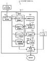
第1実施形態の3次元空間干渉判定システムの構成を示すブロック図である。図2は図1の3次元空間干渉判定システムの動作を示すフローチャートである。
Hereinafter, embodiments will be described in detail with reference to the drawings.
(First embodiment)
It is a block diagram which shows the structure of the three-dimensional spatial interference determination system of 1st Embodiment. FIG. 2 is a flowchart showing the operation of the three-dimensional spatial interference determination system of FIG.
第1実施形態の3次元空間干渉判定システム10は、3次元計測装置11、データ処理部としてのパソナルコンピュータ12(以下「PC12」と称す)、入出力装置としてのパラメータ入力部13や表示装置14などを備える。
The three-dimensional spatial
3次元計測装置11は、非接触計測により、対象構造物の表面(例えば建造物の屋内(通路や部屋)であれば内壁面)の位置および形状の3次元データ(アズビルトデータ)を計測する装置である。
The three-
例えば非接触計測する装置が3Dレーザ計測装置の場合、空間のある位置(基準位置)に3Dレーザ計測装置を配置する。そして3Dレーザ計測装置は、対象構造物に向かってレーザを走査する。次に3Dレーザ計測装置は対象構造物で反射したレーザを受光して基準位置からの距離を計測し、レーザの出力方向と距離から対象構造物の表面点の3次元座標を算出する。 For example, when the non-contact measurement device is a 3D laser measurement device, the 3D laser measurement device is arranged at a position (reference position) with space. Then, the 3D laser measuring device scans the laser toward the target structure. Next, the 3D laser measuring device receives the laser reflected by the target structure, measures the distance from the reference position, and calculates the three-dimensional coordinates of the surface point of the target structure from the output direction and distance of the laser.
すなわち、3次元計測装置11は、非接触計測により自身が設置されている基準位置を基に対象構造物の表面上までの距離を測定し、それらの形状データ(例えば、点群データ)を得る。
That is, the three-
3次元計測装置11としては、上記3Dレーザ以外にも光から電波までの指向性を持つ電磁波測定装置、および超音波測定装置、ステレオビジョン測定装置などの機器を用いることができる。
As the three-
パラメータ入力部13は、例えばキーボードやマウス、外部入力インターフェース装置などであり、ユーザの操作によって、例えばオブジェクトの配置や点群データを閲覧する際のデータを見る視点位置および角度、配置するオブジェクトの種類、位置および姿勢のパラメータ、キー操作や画面のボタンクリックによる指示などが入力された場合、その入力指示および入力データを受け付けてPC12に入力する。
The
つまりパラメータ入力部13は、3次元画像を切り取る断面の方向および位置を設定する断面設定部として機能する。表示装置14は、PC12から出力された画面や画像を表示する。具体的には画像生成部107により生成された画像などを表示する。
That is, the
PC12は、形状データ取得部100、データ蓄積部101、座標統合部102、未計測エリア識別部103、オブジェクト配置部104、干渉判定部106、画像生成部107などを備える。
The
データ蓄積部101は、例えばハードディスクドライブ装置やメモリなどであり、形状データ蓄積部101a、空間データ蓄積部101b、オブジェクトデータ蓄積部101c、干渉空間データ蓄積部101dなどの記憶領域を有する。この他、データ蓄積部101は、上記各部がデータの処理を行う上での作業領域(一時記憶領域など)として機能する。
The data storage unit 101 is, for example, a hard disk drive device or a memory, and has storage areas such as a shape
形状データ蓄積部101aには、形状データ取得部100により取得された形状データが蓄積(記憶)される。形状データは、レーザ計測により測定された空間の範囲(壁面)を示す点群データであり、例えば物が置かれていない箱形の室内では、箱形の形状を示すものとなる。この形状データは座標統合部102により必要に応じて読み出される。
The shape
空間データ蓄積部101bには、未計測エリア識別部103により識別された、計測が実施されていない空間のデータ(未計測エリアデータd2)が蓄積(記憶)される。未計測エリアとは、例えば室内に物が置かれている状況でレーザ計測を行った結果、レーザ照射点(基準位置)から物の陰になり計測されない領域である。
The spatial
オブジェクトデータ蓄積部101cには、機器や設備の形状を表現した3次元オブジェクトデータd3(オブジェクト情報)が複数記憶されている。
The object
干渉空間データ蓄積部101dには、干渉判定部106により計測済空間や未計測エリアなどとして判定された3次元空間の形状データに相当する3次元画像とオブジェクトとの干渉状況を示す干渉空間データが蓄積(記憶)される。
The interference space
形状データ取得部100は、例えば柱や配管などの物が存在する計測対象空間内のある基準位置31(図3A、図3B参照)からスキャンして計測された3次元の計測部位を示す形状データ(図3Aの計測データ32や計測済空間など)を取得する。すなわち形状データ取得部100は、このPC12の外部、つまり3次元計測装置11から入力される形状データd1を取得する。
The shape
形状データd1は3次元計測装置11が設置される位置を基準として得られる点群データであり、3次元計測装置11の位置が変われば同じ壁面を計測した点群データであっても各点の座標が異なる。座標統合部102は、その点群データの座標系を、3次元計測装置11の位置によらない同一の座標系(グローバル座標系)に統合(変換)し、統合形状データとする。
The shape data d1 is point cloud data obtained with the position where the three-
すなわち座標統合部102は、物が存在する計測対象空間内のある基準位置からスキャンして計測された3次元の計測部位を示すローカル座標系の形状データを、一つのグローバル座標系に統合して統合形状データを生成する。
That is, the coordinate
なお、計測対象空間内の異なる計測位置での複数の点群データが得られた場合、各々の基準位置で計測されたローカル座標系の複数の点群データを統合し、一つのグローバル座標系の統合形状データを生成する。 When multiple point cloud data at different measurement positions in the measurement target space are obtained, the multiple point cloud data of the local coordinate system measured at each reference position are integrated to create one global coordinate system. Generate integrated shape data.
未計測エリア識別部103は、統合形状データにおける計測位置と点群データとの位置関係から、計測が実施されていない空間(未計測エリア)(図3A参照)を識別し、識別した未計測エリアのデータd2を空間データ蓄積部101bに記憶する。
すなわち未計測エリア識別部103は、座標統合部102により統合された統合形状データに基づき、計測対象空間内で柱や配管などの物に隠れて計測されていない未計測エリアを識別し未計測エリアデータを生成する。
The unmeasured
That is, the unmeasured
オブジェクト配置部104は、生成された未計測エリアデータと計測データ32を基に計測対象空間内に計測部位と未計測エリアを表現し、これら計測部位と未計測エリアを含む3次元画像に任意のオブジェクト41を配置するための画面(図4Aなど、参照)を表示する。ここでオブジェクト41とは、配置対象の物(ロッカーや棚など)の形状を示す3次元または2次元の図形である。
The
オブジェクト配置部104は、画面における干渉の判定対象となる対象構造物(部屋や通路に後付されたロッカーや棚、柱、配管や補強部材、今後設置する機材など)の配置操作に応じて、対応する3次元オブジェクトをオブジェクトデータ蓄積部101cから読み出して点群データ中に配置する。
The
干渉判定部106は、3次元画像に配置されたオブジェクト41と、3次元画像の計測データ32(計測部位)および未計測エリア33の少なくとも一方との干渉の有無を判定する。つまり干渉判定部106は、ユーザが配置したオブジェクトと他のデータ(測定済空間のデータや未測定空間のデータなど)との干渉を判定する。
The
干渉判定部106は干渉空間データ生成部106aを有する。干渉空間データ生成部106aは、干渉判定部106が干渉ありと判定した干渉部位に相当する干渉空間データを生成し干渉空間データ蓄積部に101dに蓄積(記憶)する。
The
干渉判定部106は、オブジェクト41と計測データ32(計測部位)との第1干渉部位51の有無、およびオブジェクト41と未計測エリア33との第2干渉部位52の有無をそれぞれ識別する(図5B参照)。
The
干渉空間データ生成部106aは、干渉判定部106により干渉ありと判定された第1干渉部位51に相当する第1干渉空間データと第2干渉部位52に相当する第2干渉空間データとをそれぞれ生成し、干渉空間データ蓄積部101dに蓄積(記憶)する。
The interference spatial
画像生成部107は、データ蓄積部101から計測済の形状データ(計測データ32)、未計測空間のデータ(未計測エリア33のデータ)、オブジェクトデータ(配置した機器、設備の図形データ)、干渉空間データ(干渉部位51、52のデータ)などを読み出して、これらのデータを基に3次元画像30を生成し、生成した3次元画像30に干渉部位51、52を重ね合わせた画像を生成し表示部14へ出力する。つまり画像生成部107は点群データや干渉判定結果などの表示画像を生成する。
The
画像生成部107は、干渉空間データを基に、3次元画像30に干渉部位51、52(図5A参照)を重ね合わせた画像を生成し表示部14へ出力する。なおこの例(図5A)の干渉部位51は小さいため図5Bを参照。
The
画像生成部107は、干渉空間データを基に、オブジェクト41に干渉部位52(図6A参照)を重ねた画像を生成し出力する。なお3次元画像30の計測部位や未計測エリアにオブジェクト41との干渉部位51、52が重なる場合、画像生成部107は、その両方に干渉部位51、52を重ねた画像を生成し出力する。
The
この際、画像生成部107は、干渉部位52をオブジェクト41とは異なる表示形態にしてオブジェクト41と重ねた画像を生成し表示部14へ出力する。異なる表示形態とは例えば干渉部位52の模様や塗りつぶしの色を元のオブジェクト41の模様や塗りつぶしの色と異ならせることをいう。
At this time, the
画像生成部107は、第1干渉部位51と第2干渉部位52とを異なる表示形態で3次元画像30に重ね合わせた画像を生成し出力する(図5B、図6B参照)。
The
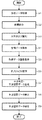
次に、図2のフローチャートおよび図3A乃至図7Bを参照してこの3次元空間干渉判定システムの動作を説明する。
この3次元空間干渉判定システム10の場合、計測対象となる計測対象空間内の複数の計測位置に3次元計測装置11を配置し、各位置において3次元計測装置11が計測を行い、形状データd1を取得し(ステップS1)、形状データ蓄積部101aに保存する。
Next, the operation of the three-dimensional spatial interference determination system will be described with reference to the flowchart of FIG. 2 and FIGS. 3A to 7B.
In the case of this three-dimensional spatial
次に、座標統合部102は、形状データ蓄積部101aに保存された各々の形状データd1を読み出し、異なるローカル座標系で表された形状データの座標系を同一の座標系(グローバル座標系)に変換し(ステップS2)、1つの形状データに統合する。統合された形状データd2は、一旦、形状データ蓄積部101aに保存される。
Next, the coordinate
続いて、未計測エリア識別部103は、計測が実施されていない未計測エリア33を識別する(ステップS3)。
Then, the unmeasured
詳細に説明すると、未計測エリア識別部103は、統合された形状データを形状データ蓄積部101aから読み出し、読み出した形状データのうち、計測位置と計測データ32の間を計測済みで構造物が存在しない空間、その他の空間を計測が実施されていない未計測エリア33として識別する。
More specifically, the unmeasured
複数の計測位置において未計測エリア33を識別した結果の積集合(AND演算)をとることで、最終的な計測空間内の未計測エリア33を得ることができる。
By taking the product set (AND operation) of the results of identifying the
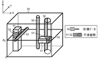
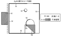
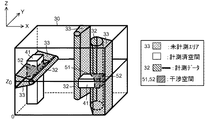
図3A、図3Bは、計測位置と付した位置で形状計測を行ったときに、計測位置と計測データ32の位置関係から未計測エリア33を識別し、未計測エリア33に相当する3次元データを生成し表示した例である。また、図3Bの平面図は、図3Aに示す3次元画像(空間画像)を任意の位置で切断したときの断面(平面)を示す例である。
3A and 3B are three-dimensional data corresponding to the
なお図3Aの左上に方向線を示しているが、断面に垂直な方向(法線方向)をX軸方向、Y軸方向、Z軸方向とし、Z軸方向の断面はXY平面、Y軸方向の断面はXZ平面、X軸方向の断面はYZ平面などと定義する。 Note that, although direction lines are shown in the upper left of FIG. 3A, the directions (normal directions) perpendicular to the cross section are the X axis direction, the Y axis direction, and the Z axis direction, and the cross section in the Z axis direction is the XY plane, the Y axis direction. Is defined as the XZ plane, and the cross section in the X-axis direction is defined as the YZ plane.
断面位置(図3AではZ軸の座標Z=Z0)は、ユーザの入力により自由に変更でき、XY平面上に存在する構造物の計測データ32(図の太い実線部)、未計測エリア33などを表示できる。
The cross-section position (Z-axis coordinate Z=Z 0 in FIG. 3A) can be freely changed by the user's input, and the measurement data 32 (thick solid line portion in the figure) of the structure existing on the XY plane, the
図3Bに示す断面図中に示した破線矢印は、計測位置から照射されるレーザの一例であり、未計測エリア識別部103は、レーザの照射方向について計測位置から計測データ32間を計測済み空間、計測データ32以降の空間を未計測エリア33と識別する。
The broken line arrow shown in the cross-sectional view shown in FIG. 3B is an example of the laser irradiated from the measurement position, and the unmeasured
そして、未計測エリア識別部103は、識別した未計測エリア33、および計測済み空間に関する空間データd2を空間データ蓄積部101bに保存する(ステップS4)。
Then, the unmeasured
画像生成部107は、データ蓄積部101に記憶されている各データ(計測済空間、未計測エリア33、干渉空間、オブジェクト41などのデータ)を読み出し、3次元計測装置11から取得した形状データに重ね合わせ、または形状データとは別個にして、3次元画像または2次元画像を生成し、表示部14へ出力することで表示部14の画面に表示する(ステップS5)。
The
3次元画像の場合、ユーザの入力により、視点の位置・姿勢、点群データの表示倍率といったパラメータを自由に変更することができる。また、2次元画像は、上面図、側面図、断面図など形状データを2次元的に表現した画像を生成でき、ユーザの入力により視点位置や断面平面、断面位置などのパラメータをパラメータ入力部13より入力および設定することで、3次元画像から切り取る断面を自由に変更することができる。また、識別した未計測エリア33などの空間データも合わせて表示する。
In the case of a three-dimensional image, parameters such as the position/orientation of the viewpoint and the display magnification of the point cloud data can be freely changed by the user's input. In addition, the two-dimensional image can generate an image that two-dimensionally represents shape data such as a top view, a side view, and a cross-sectional view, and parameters such as the viewpoint position, the cross-sectional plane, and the cross-sectional position can be input by the user. By inputting and setting more, the cross section cut out from the three-dimensional image can be freely changed. Further, the spatial data such as the identified
オブジェクト情報が格納されているオブジェクトデータ蓄積部101cに記憶されている機器や設備の形状を表現したオブジェクトデータ郡(集まり)の中から、ユーザが干渉を確認したい所望のオブジェクト41を選択し配置する位置を指定することで、オブジェクト配置部104は、指定されたオブジェクトデータd3を読み込み、形状データの中に配置する(ステップS6)。
From the object data group (collection) expressing the shapes of the devices and equipment stored in the object
配置するオブジェクト41の種類の選択や配置位置、姿勢の設定はユーザの入力操作によって行われる。また、オブジェクトデータd3は記憶されているデータに限らず、ユーザの入力によって任意の形状の3次元データを作成し、ユーザ固有のオブジェクトデータとしてオブジェクトデータ蓄積部101cに登録し、形状データとの干渉判定に利用してもよい。
The selection of the type of the
図4は直方体形状のオブジェクトデータを形状データの中に配置したときの配置例(表示画像の一例)を示している。図4に示すように、オブジェクト41は、一つとは限らず、複数配置してもよい。
FIG. 4 shows an arrangement example (an example of a display image) when the rectangular parallelepiped object data is arranged in the shape data. As shown in FIG. 4, the
干渉判定部106は、オブジェクト配置部104により配置されたオブジェクト41について、測定済空間のデータと未測定空間のデータとの干渉判定を行い(ステップS7)、干渉空間データを生成する。
The
干渉判定は、3次元のオブジェクトデータ内に形状データが存在する(重なる)か否かを判定する。オブジェクト41の3次元データの外形内に形状データが含まれる場合、その位置(空間)データを生成し、干渉空間データとする。
The interference determination determines whether or not shape data exists (overlaps) in the three-dimensional object data. When the shape data is included in the outer shape of the three-dimensional data of the
また干渉判定部106は、形状データとの干渉だけでなく、未計測エリア33との干渉判定を行う。この場合もオブジェクト41に含まれる未計測エリア33を検出することで、干渉の判定を行い、未計測エリア33との干渉空間データを生成する。
The
ここで、オブジェクト41と未計測エリア33との干渉判定動作(手順)を詳細に説明する。
計測対象空間を予め設定した所定の大きさの複数のブロック(例えば、一辺10mmの立方体)に分割する。ブロックの大きさや形状についてはこの例に限定されるものではなく、対象空間の大きさなどに応じて適宜設定してよい。
Here, the collision determination operation (procedure) between the
The measurement target space is divided into a plurality of preset blocks having a predetermined size (for example, a cube having a side of 10 mm). The size and shape of the block are not limited to this example, and may be appropriately set according to the size of the target space.
干渉判定部106は、各ブロックが未計測エリア33に含まれているか否かを判定した結果に応じて、対象のブロックに属性を付与し、未計測エリア33の情報を各ブロックの属性値として持たせる。
The
次に、干渉判定部106は、配置したオブジェクト41の一部を含むブロックを抽出し、各ブロックの属性を確認する。オブジェクト41を含むブロックのうち、未計測エリア33の情報を持つものは、そのブロック内で未計測エリア33と干渉するものと判定する。
Next, the
これにより、干渉判定部106は、オブジェクト41と未計測エリア33が干渉するブロックを検出し、未計測エリア33との干渉空間データを生成する。この他、未計測エリア33とオブジェクト41の共通部分を直接抽出してもよく、また干渉空間データを生成してもよい。
Thereby, the
ここから元の処理手順に戻ると、画像生成部107は、ステップS7の処理で干渉判定部106が干渉判定を行った結果、生成した未計測エリア33を点群データ上に重ね合わせて互いの干渉画像を生成し(ステップS8)、表示部14へ出力することで、該画像を表示部14の画面に表示する。
Returning to the original processing procedure, the
図5A、図5Bは干渉空間データの生成例(表示画像の一例)であり、図5Aは3次元画像、図5Bは平面画像の生成例である。 5A and 5B are examples of generation of interference spatial data (examples of display images), FIG. 5A is a three-dimensional image, and FIG. 5B is a generation example of a plane image.
なお、パラメータ入力部13により3次元画像を切り取る断面の方向および位置が設定されることで、画像生成部107は、パラメータ入力部13により設定された断面の方向および位置を基に、図5Bに示すようなZ軸方向の設定位置Z0(任意の位置)で3次元画像を切り取った2次元の画像、つまり断面画像(平面画像)を表示する。
Note that the
また、図5B(断面図)に示すように、オブジェクト41と計測データ32との干渉部51と、オブジェクト41と未計測エリア33との干渉部52とを、例えばその部分の色や模様、その他表示形態を変えることで、干渉状況の違いを区別して表示する。
Further, as shown in FIG. 5B (cross-sectional view), an
干渉空間データに対応するオブジェクト41の干渉部位を特定し、オブジェクト41全体とその一部の干渉部位との表示形式を変更して表示した場合の表示例(一例)を図6A、図6Bに示す。
6A and 6B show display examples (one example) when the interference part of the
図7A、図7Bは、オブジェクト41を配置した計測済空間の空間データに、未計測エリア33の空間データをさらに重ね合わせて表示した場合の表示例(一例)である。
7A and 7B are display examples (one example) when the spatial data of the
最後に、画像生成部107は、干渉空間データを干渉空間データ蓄積部101bに保存する(ステップS9)。
Finally, the
以上説明したようにこの第1実施形態によれば、表示された画像を見ることで、計測対象空間に配置したオブジェクト41のうち、計測データ32と干渉する部分、および未計測エリア33と干渉する部分を視覚的に確認できるようになり、機器の干渉を確認しながら、物の収まり具合や通過可否を判定できる。
As described above, according to the first embodiment, by seeing the displayed image, the portion of the
また、作業前の現場確認時に注意して確認する部分を未計測部分との干渉部に限定でき、現場確認が必要な場合も現場作業工程を短縮できる。 In addition, the part to be checked carefully at the time of site confirmation before work can be limited to the interference part with the unmeasured part, and the site work process can be shortened when site confirmation is required.
(第2実施形態)
図8は第2実施形態の3次元空間干渉判定システムの構成を示すブロック図である。図9は図8の3次元空間干渉判定システムの動作を示すフローチャートである。なお第2実施形態の構成を説明するにあたり第1実施形態と同じ構成には同一の符号を付しその説明は省略する。
(Second embodiment)
FIG. 8 is a block diagram showing the configuration of the three-dimensional spatial interference determination system of the second embodiment. FIG. 9 is a flowchart showing the operation of the three-dimensional spatial interference determination system of FIG. In describing the configuration of the second embodiment, the same components as those of the first embodiment are designated by the same reference numerals and the description thereof will be omitted.
図8に示すように、第2実施形態の場合、PC12は調査範囲設定部109を備える。調査範囲設定部109は、調査範囲を設定するための画面を表示部14に表示する。表示された画面の入力欄にユーザが平面の法線方向(X軸,Y軸,Z軸のいずれか)、調査範囲の始点・終点位置を入力し、確定操作を行うことで、入力された調査範囲がデータ蓄積部101に設定される。
As shown in FIG. 8, in the case of the second embodiment, the
調査範囲設定部109は、パラメータ入力部13により入力および設定された断面と直交する方向に調査範囲を設定する。
The survey
調査範囲が設定されている場合、干渉空間データ生成部106aは、調査範囲内の干渉部位を、設定された方向に沿って、始点・終点位置に範囲で干渉空間データの和集合を取った干渉空間データを生成する。画像生成部107は、調査範囲内の3次元画像の範囲でオブジェクト41と形状データ(計測部位32)との干渉部位51およびオブジェクト41と未計測エリア33との干渉部位52を重ね合わせた画像を生成する。
When the investigation range is set, the interference space
続いて、図9のフローチャートおよび図10A乃至図11Bを参照して第2実施形態の3次元空間干渉判定システムの動作を説明する。なお第2実施形態の動作を説明するにあたり第1実施形態と同じ動作には同一の符号を付しその説明は省略する。
この第2実施形態では、図9のステップS1からステップS7までの処理ステップは、第1実施形態と同じであり、ここまでの処理によって、形状データとオブジェクト41との干渉判定が行われる。
Next, the operation of the three-dimensional spatial interference determination system of the second embodiment will be described with reference to the flowchart of FIG. 9 and FIGS. 10A to 11B. In describing the operation of the second embodiment, the same operation as that of the first embodiment will be denoted by the same reference numeral, and the description thereof will be omitted.
In the second embodiment, the processing steps from step S1 to step S7 in FIG. 9 are the same as those in the first embodiment, and the interference determination between the shape data and the
続いて、計測対象範囲について、任意の法線方向の平面を設定し、その法線方向を調査方向とする。 Subsequently, a plane in an arbitrary normal direction is set for the measurement target range, and the normal direction is set as the investigation direction.
次に、その平面の法線方向に沿って調査範囲を設定する。ユーザの入力により、平面の法線方向、調査範囲の始点・終点位置を設定することで、調査範囲が設定される(ステップS10)。 Next, the survey area is set along the normal to the plane. The survey range is set by the user's input by setting the normal direction of the plane and the start and end positions of the survey range (step S10).
設定した調査範囲について、調査方向に沿って、設定された始点・終点位置の範囲で、干渉空間データの積集合をとり、干渉空間データを表示する(ステップS8)。なお3次元画像については、設定した調査範囲を包含する直方体を表示することを選んでもよい。 With respect to the set investigation range, the intersection set of intersection space data is taken in the range of the set start point/end point position along the investigation direction, and the interference space data is displayed (step S8). For the three-dimensional image, it may be selected to display a rectangular parallelepiped including the set survey range.
図10AはZ軸方向を調査方向とし、Z0≦Z≦Z1を調査範囲に設定したときの3次元画像の表示例、図10Bは図10Aの3次元画像を座標Z0〜Z1の位置で切り取った断面の一例を示す図である。 Figure 10A is a research direction Z-axis direction, Z 0 ≦ Z display example of a three-dimensional image of ≦ Z 1 when set to Scope, FIG 10B is a three-dimensional image of Figure 10A in the coordinate Z 0 to Z 1 It is a figure which shows an example of the cross section cut off at a position.
図11AはZ軸方向を調査方向とし、Z1≦Z≦Z2を調査範囲に設定したときの3次元画像の表示例、図11Bは図11Aの3次元画像を座標Z1〜Z2の位置で切り取った断面の一例を示す図である。 FIG. 11A shows a display example of a three-dimensional image when Z 1 ≦Z≦Z 2 is set as the investigation range with the Z-axis direction as the investigation direction, and FIG. 11B shows the coordinates of Z 1 -Z 2 of the 3D image of FIG. 11A. It is a figure which shows an example of the cross section cut off at a position.
以上のようにこの第2実施形態によれば、第1実施形態の効果に加えて、調査範囲設定部109が設定した調査範囲内の空間における干渉空間の可視化を行うことで、注目領域の機器の干渉を確認しながら配置可否や通過可否を視覚的に判定できる。
As described above, according to the second embodiment, in addition to the effects of the first embodiment, by visualizing the interference space in the space within the investigation range set by the investigation
(第3実施形態)
図12は第3実施形態の3次元空間干渉判定システムの構成を示すブロック図である。なお第3実施形態の構成を説明するにあたり第1および第2実施形態と同じ構成には同一の符号を付しその説明は省略する。
(Third Embodiment)
FIG. 12 is a block diagram showing the configuration of the three-dimensional spatial interference determination system of the third embodiment. In describing the configuration of the third embodiment, the same components as those of the first and second embodiments are designated by the same reference numerals, and the description thereof will be omitted.
図12に示すように、第3実施形態の場合、PC12はオブジェクト経路設定部110を備える。
As shown in FIG. 12, in the case of the third embodiment, the
オブジェクト経路設定部110は、計測対象空間内に配置したオブジェクト41を移動させる移動経路を設定する。
The object
移動経路が設定されている場合、干渉判定部106は、オブジェクト41を移動させた移動経路上の任意の位置において、オブジェクト41と形状データ32(計測部位)との干渉の有無、およびオブジェクト41と未計測エリア33との干渉の有無を判定する。干渉空間データ生成部106aは、干渉判定部106により干渉ありと判定された干渉部位の移動位置毎または移動時間毎の干渉空間データ(時系列干渉空間データ)を生成する。
When the movement route is set, the
画像生成部107は、時系列干渉空間データから任意の位置または時刻における干渉空間データを抽出し、その位置または時刻でのオブジェクト41と形状データ32(計測部位)を重ね合わせた画像、および/またはオブジェクト41と未計測エリア33とを重ね合わせた画像を生成する。
The
画像生成部107は、移動経路上の各位置における時系列干渉空間データの和集合データを生成し、生成した和集合データと形状データ32(計測部位)を重ね合わせた画像、および/または生成した和集合データと未計測エリア33とを重ね合わせた画像を生成する。
The
続いて、図13のフローチャートと図14A乃至図15Bを参照してこの3次元空間干渉判定システムの動作を説明する。図13は図12の3次元空間干渉判定システムの動作を示すフローチャートである。図14A、図14Bはオブジェクト41の移動経路1401を設定した状況を示した図であり、図14Aはオブジェクト41の移動経路1401を表示した3次元画像、図14Bは図14Aの3次元画像を座標Z0の位置で切り取った断面の一例を示す図である。なお第3実施形態の動作を説明するにあたり第1実施形態または第2実施形態と同じ動作には同一の符号を付しその説明は省略する。
Subsequently, the operation of the three-dimensional spatial interference determination system will be described with reference to the flowchart of FIG. 13 and FIGS. 14A to 15B. FIG. 13 is a flowchart showing the operation of the three-dimensional spatial interference determination system of FIG. 14A and 14B are diagrams showing a situation in which the
この第3実施形態では、ステップS1乃至ステップS5までの動作は第1実施形態と同じである。 In this third embodiment, the operation from step S1 to step S5 is the same as that of the first embodiment.
そして、ユーザが、干渉を確認すべき所望のオブジェクト41を計測対象空間(形状データ)上に配置し(ステップS6)、経路設定ボタンなどをクリックすると、オブジェクト経路設定部110は、例えば図14Aに示すように、計測対象空間内でのオブジェクト41の中心点1406などを表示し、その中心点1406の位置を移動開始位置として設定する(ステップS11)。
Then, when the user arranges the desired
ユーザの操作によってオブジェクト41を移動させると、オブジェクト経路設定部110は、移動に伴い移動開始位置からオブジェクト41の中心点1406が通過する通過ポイント1402の3次元位置情報を順に追加し、最終的な移動停止位置までの通過ポイント1402を設定する。通過ポイント1402は、その3次元座標をユーザの入力(点群画像のマウスクリックや数値入力)により設定する。
When the
次に、オブジェクト経路設定部110は、通過ポイント1402間のオブジェクト41の位置を補完する。これは、例えば、通過ポイント1402間を直線で結び、その直線上を移動ステップ量ずつ、オブジェクト41を移動させたときの3次元座標を求めることで補完する。なお、通過ポイント1402間の補完は、直線の軌道だけでなく、曲線の軌道(移動)として設定してもよい。
Next, the object
以上により、オブジェクト41の移動開始位置から移動経路1401上を動くオブジェクト41の時系列の変化が伴う3次元位置情報(点の移動情報)を生成する。なお時系列の変化ではなく、通過ポイント1402の番号の順で移動方向を決めるようにしてもよい。
As described above, three-dimensional position information (movement information of a point) that accompanies a time series change of the
移動経路設定後、干渉判定部106は、オブジェクト41の時系列の3次元位置情報を基に、各時刻におけるオブジェクト41と計測データ32との干渉判定、およびオブジェクト41と未計測エリア33との干渉判定を行い、干渉ありと判定した干渉部位の移動位置毎または移動時間毎の干渉空間データ(時系列干渉空間データ)を生成する(ステップS7)。
After setting the movement route, the
画像生成部107は、時系列干渉空間データを計測データ32上に重ね合わせた画像を生成し、表示部14に出力することで表示する(ステップS8)。ここでは、時系列の干渉空間データから、任意の時刻(任意の通過位置)を選択して表示する。
The
この場合は、第1実施形態の図5Aから図7Bに示したように、その時刻のオブジェクト41や干渉空間データが表示されることになる。なお時系列の干渉空間データの和集合を求め、図15Aに示すように、移動経路上のオブジェクト41を3次元画像として表示してもよい。この表示方法では、移動経路全体において干渉がある部分を一度に確認することができる。図15Bには、図15Aに示したオブジェクト41の移動経路のうち、計測部位32や未測定エリア33との干渉が発生した部位51、52の平面を切り出して表示した例を示す。
In this case, as shown in FIGS. 5A to 7B of the first embodiment, the
干渉空間表示後の動作、つまりステップS9の干渉空間データ保存処理について第1実施形態と同様である。 The operation after the display of the interference space, that is, the interference space data storage process of step S9 is the same as that of the first embodiment.
以上説明したようにこの第3実施形態によれば、第1実施形態の効果に加えて、移動して配置する機器などのオブジェクト41の移動経路を設定するオブジェクト経路設定部110を設け、オブジォクト41が移動する各時刻の位置のオブジォクト41と計測データ32との干渉部位51、および未計測エリア33とオブジォクト41との干渉部位52を可視化することで、機器や設備の搬入・搬出計画や調査機器のアクセス経路の検討を視覚的に判断しながら実施することができる。
As described above, according to the third embodiment, in addition to the effects of the first embodiment, the object
なお、この第3実施形態の構成に、さらに第2の実施形態に示した調査範囲設定部109を加えて調査範囲を設定した上で、調査範囲内の時系列の干渉空間データを表示するようにしてもよい。
In addition, after adding the investigation
(第4実施形態)
図16は第4実施形態の3次元空間干渉判定システムの構成を示すブロック図である。図17は図16の3次元空間干渉判定システムの動作を示すフローチャートである。この第4実施形態の構成は、第1の実施形態に示した構成から3次元計測装置11、座標統合部102、未計測エリア識別部103を省き、これら装置および各部から得られるデータ(形状データd1、未計測エリアデータd2)を予めPC12のデータ蓄積部101に蓄積しておき、PC12だけで処理を行うよう構成したものであり、PC12に未計測エリア取得部111を追加している。
(Fourth Embodiment)
FIG. 16 is a block diagram showing the configuration of the three-dimensional spatial interference determination system of the fourth embodiment. FIG. 17 is a flowchart showing the operation of the three-dimensional spatial interference determination system of FIG. The configuration of the fourth embodiment omits the three-
この場合、データ取得部100は、データ蓄積部101の形状データ蓄積部101aから形状データd1を取得し、未計測エリア取得部111に渡す。未計測エリア取得部111は、データ蓄積部101の空間データ蓄積部101bから未計測エリアデータd2を取得し、未計測エリアデータd2と形状データd1とをオブジェクト配置部104へ渡す。
In this case, the
形状データd1は、未計測エリア取得部111を介さずにデータ取得部100から、直接、オブジェクト配置部104へ渡してもよい。すなわちデータ取得部100と未計測エリア取得部111は、形状データd1と未計測エリアデータd2とをデータ蓄積部101(蓄積部)から読み出す取得部として機能する。
The shape data d1 may be directly passed from the
また、この場合、オブジェクト配置部104は、物が存在する計測対象空間内のある基準位置からスキャンして計測された3次元の計測部位を示す形状データd1と、この形状データd1に基づき計測対象空間内で物に隠れて計測されていない未計測エリアを識別して得られた未計測エリアデータd2とを基に、計測対象空間内に表現した計測部位と未計測エリアを含む3次元画像に任意のオブジェクトを配置するための画面を表示する配置部として機能する。
In addition, in this case, the
この例では、形状データd1と未計測エリアデータd2を予め記憶しておくものとしたが、未計測エリア取得部111を削除し、未計測エリア識別部103を残し、未計測エリア識別部103が、形状データ蓄積部101aから取得した形状データd1を基に未計測エリアデータd2を生成するようにしてもよい。
In this example, the shape data d1 and the unmeasured area data d2 are stored in advance, but the unmeasured
以下、図17のフローチャートを参照してこの第4実施形態の3次元空間干渉判定システム10の動作を説明する。なお図17を参照して第4実施形態の動作を説明するにあたり、上記第1乃至第3実施形態と同じ説明には同一のステップ番号(符号)を付しその説明は省略する。
The operation of the three-dimensional spatial
この第4実施形態の場合、形状データ取得部100は、予め対象空間をスキャンしてデータ蓄積部101の形状データ蓄積部101aに記憶しておいた形状データd1を読み出し取得する(図17のステップS1)。
In the case of the fourth embodiment, the shape
続いて、未計測エリア取得部111は、未計測エリアデータd2を記憶する空間データ蓄積部101bから未計測エリアデータd2を取得し(ステップS13)、オブジェクト配置部104に渡す。オブジェクト配置部104は、各取得部により得られた形状データd1および未計測エリアデータd2を含む3次元画像を表示部14へ出力し、オブジェクト配置用の画面を表示する。
Subsequently, the unmeasured
その後のステップS6からステップS9までの処理は、第1実施形態と同様に、機器の3次元オブジェクトデータを形状データ中に配置し、形状データ(計測済空間)および未計測エリア33との干渉を判定して表示する。
In the subsequent processing from step S6 to step S9, like the first embodiment, the three-dimensional object data of the device is arranged in the shape data, and the interference with the shape data (measured space) and the
また、図16に示した第4実施形態の構成に、第2および第3実施形態に示した調査範囲設定部109および/またはオブジェクト経路設定部110などの構成を加えることで、設定した調査範囲の干渉データの閲覧やオブジェクト41の移動経路中の干渉範囲の確認を行うことができる。
Further, the investigation range set by adding the composition of the investigation
以上説明したようにこの第4実施形態によれば、計測対象の空間を予め3次元計測装置にて計測しておき、その形状データd1や未計測エリアデータd2のうち少なくとも形状データd1を蓄積しておくことで、PC12単体でも第1から第3実施形態と同様に、3次元空間に配置したオブジェクトと計測済空間や未計測エリアとの干渉を判定し、それぞれの部分との干渉状況を色分け表示することで、対象空間の物の収まりや通過可否を利用者が容易に判定できるようになる。
As described above, according to the fourth embodiment, the space to be measured is measured in advance by the three-dimensional measuring device, and at least the shape data d1 of the shape data d1 and the unmeasured area data d2 is accumulated. As a result, even with the
本発明の実施形態を説明したが、この実施形態は、例として提示したものであり、発明の範囲を限定することは意図していない。この新規な実施形態は、その他の様々な形態で実施されることが可能であり、発明の要旨を逸脱しない範囲で、種々の省略、置き換え、変更を行うことができる。これら実施形態やその変形は、発明の範囲や要旨に含まれるとともに、特許請求の範囲に記載された発明とその均等の範囲に含まれる。 Although the embodiment of the present invention has been described, this embodiment is presented as an example and is not intended to limit the scope of the invention. The novel embodiment can be implemented in various other forms, and various omissions, replacements, and changes can be made without departing from the gist of the invention. These embodiments and their modifications are included in the scope and gist of the invention, and are also included in the invention described in the claims and the scope of equivalents thereof.
また上記実施形態に示したPC12の各構成要素を、コンピュータのハードディスク装置などのストレージにインストールしたプログラムで実現してもよく、また上記プログラムを、コンピュータ読取可能な電子媒体:electronic mediaに記憶しておき、プログラムを電子媒体からコンピュータに読み取らせることで本発明の機能をコンピュータが実現するようにしてもよい。電子媒体としては、例えばCD−ROM等の記録媒体やフラッシュメモリ、リムーバブルメディア:Removable media等が含まれる。さらに、ネットワークを介して接続した異なるコンピュータに構成要素を分散して記憶し、各構成要素を機能させたコンピュータ間で通信することで実現してもよい。
Further, each component of the
10…3次元空間干渉判定システム
11…3次元計測装置
12…PC
13…パラメータ入力部
14…表示部
100…形状データ取得部
101…データ蓄積部
101a…形状データ蓄積部
101b…空間データ蓄積部
101c…オブジェクトデータ蓄積部
101d…干渉空間データ蓄積部
102…座標統合部
103…未計測エリア識別部
104…オブジェクト配置部
106…干渉判定部
106a…干渉空間データ生成部
107…画像生成部
109…調査範囲設定部
110…オブジェクト経路設定部
111…未計測エリア取得部
d1…形状データ
d2…未計測エリアデータ
d3…3次元オブジェクトデータ
10... 3D spatial
13...
Claims (14)
前記3次元画像に配置されたオブジェクトと、前記3次元画像の前記計測部位および前記未計測エリアの少なくとも一方との干渉の有無を判定する干渉判定部と
を具備する3次元空間可視化装置。 Shape data indicating a three-dimensional measurement site that is measured by scanning from a certain reference position in the measurement target space in which an object exists, and based on this shape data, measurement is performed while hiding behind the object in the measurement target space. Screen for arranging an arbitrary object on a three-dimensional image including the measurement site and the unmeasured area expressed in the measurement target space based on the unmeasured area data obtained by identifying the unmeasured area And the placement section that displays
A three-dimensional space visualization device comprising: an object arranged in the three-dimensional image; and an interference determination unit that determines the presence or absence of interference with at least one of the measurement site and the unmeasured area of the three-dimensional image.
前記形状データと前記未計測エリアデータとを前記蓄積部から読み出す取得部と
を具備する請求項1記載の3次元空間可視化装置。 A storage unit that stores the shape data and the unmeasured area data,
The three-dimensional space visualization device according to claim 1, further comprising: an acquisition unit that reads the shape data and the unmeasured area data from the storage unit.
前記形状データに基づき、前記未計測エリアを識別し前記未計測エリアデータを生成す
る未計測エリア識別部と
を具備する請求項1記載の3次元空間可視化装置。 A measurement data acquisition unit that acquires the shape data from the outside,
The three-dimensional space visualization device according to claim 1, further comprising: an unmeasured area identification unit that identifies the unmeasured area based on the shape data and generates the unmeasured area data.
干渉空間データ生成部を具備する請求項1および請求項3いずれか1項に記載の3次元空間可視化装置。 The three-dimensional space visualization device according to any one of claims 1 and 3, wherein the interference determination unit includes an interference space data generation unit that generates interference space data corresponding to an interference site determined to have interference.
前記干渉部位を、前記オブジェクトとは異なる表示形態にして前記オブジェクトと重ねた画像を生成し出力する請求項5に記載の3次元空間可視化装置。 The image generation unit,
The three-dimensional space visualization device according to claim 5, wherein an image in which the interference portion is displayed in a display form different from that of the object is superimposed and the image is generated and output.
前記オブジェクトと前記計測部位との第1干渉部位の有無、および前記オブジェクトと前記未計測エリアとの第2干渉部位の有無をそれぞれ識別し、
前記干渉空間データ生成部は、
前記干渉判定部により干渉ありと判定された前記第1干渉部位に相当する第1干渉空間データと前記第2干渉部位に相当する第2干渉空間データとをそれぞれ生成する請求項4記載の3次元空間可視化装置。 The interference determination unit,
The presence or absence of a first interference site between the object and the measurement site, and the presence or absence of a second interference site between the object and the unmeasured area are respectively identified,
The interference space data generation unit,
The three-dimensional structure according to claim 4, wherein first interference space data corresponding to the first interference site and second interference space data corresponding to the second interference site determined to have interference by the interference determination unit are generated respectively. Space visualization device.
前記断面設定部により設定された断面と直交する方向に調査範囲を設定する調査範囲設定部とを備え、
前記干渉空間データ生成部は、
前記調査範囲内の前記干渉部位を前記方向に沿って、設定された位置の範囲で、前記干渉空間データの和集合を取った干渉空間データを生成し、
前記画像生成部は、
前記調査範囲内の3次元画像および前記オブジェクトの少なくとも一方に前記干渉部位を重ね合わせた画像を生成する請求項5または請求項6いずれか記載の3次元空間可視化装置。 A cross-section setting unit for setting the direction and position of the cross-section for cutting out the three-dimensional image,
A survey range setting unit that sets a survey range in a direction orthogonal to the cross section set by the cross section setting unit,
The interference space data generation unit,
Along the direction of the interference site in the investigation range, in the range of the set position, to generate the interference space data obtained by taking the union of the interference space data,
The image generation unit,
7. The three-dimensional space visualization device according to claim 5, wherein an image in which the interference site is superimposed on at least one of the three-dimensional image and the object within the investigation range is generated.
前記干渉判定部は、
前記オブジェクトを移動させた前記移動経路上の任意の位置において、前記オブジェクトと前記計測部位との干渉の有無、および前記オブジェクトと前記未計測エリアとの干渉の有無を判定し、
前記干渉空間データ生成部は、
前記干渉判定部により干渉ありと判定された干渉部位の移動位置毎または移動時間毎の時系列干渉空間データを生成する請求項4に記載の3次元空間可視化装置。 A setting unit that sets a movement path of the object in the measurement target space,
The interference determination unit,
At any position on the movement path where the object is moved, it is determined whether or not there is interference between the object and the measurement site, and whether or not there is interference between the object and the unmeasured area,
The interference space data generation unit,
The three-dimensional space visualization device according to claim 4, wherein time-series interference space data is generated for each moving position or each moving time of an interference portion determined to have interference by the interference determining unit.
前記時系列干渉空間データから任意の位置または時刻における干渉空間データを抽出し、その位置または時刻での前記オブジェクトと前記計測部位を重ね合わせた画像、および/または前記オブジェクトと前記未計測エリアとを重ね合わせた画像を生成する請求項10に記載の3次元空間可視化装置。 The image generation unit,
Interference space data at an arbitrary position or time is extracted from the time-series interference space data, and an image obtained by superimposing the object and the measurement site at the position or time, and/or the object and the unmeasured area are displayed. The three-dimensional space visualization device according to claim 10, wherein the superimposed images are generated.
前記移動経路上の各位置における前記時系列干渉空間データの和集合データを生成し、生成した前記和集合データと前記計測部位を重ね合わせた画像、および/または生成した前記和集合データと前記未計測エリアとを重ね合わせた画像を生成する請求項10記載の3次元空間可視化装置。 The image generation unit,
An union data of the time-series interference space data at each position on the movement route is generated, an image in which the union data generated and the measurement site are superposed, and/or the union data generated and The three-dimensional space visualization device according to claim 10, which generates an image in which the measurement area is superimposed.
干渉判定部によって、前記3次元画像に配置されたオブジェクトと、前記3次元画像の前記計測部位および前記未計測エリアの少なくとも一方との干渉の有無を判定する3次元空間可視化方法。 Shape data indicating a three-dimensional measurement site that is measured by scanning from a certain reference position in the measurement target space in which an object exists, and based on this shape data, measurement is performed while hiding behind the object in the measurement target space. For arranging an arbitrary object in a three-dimensional image including the measurement site and the unmeasured area expressed in the measurement target space based on the unmeasured area data obtained by identifying the unmeasured area Display the screen,
A three-dimensional space visualization method for determining the presence or absence of interference between an object arranged in the three-dimensional image and at least one of the measurement site and the unmeasured area of the three-dimensional image by an interference determination unit .
前記3次元画像に配置されたオブジェクトと、前記3次元画像の前記計測部位および前記未計測エリアの少なくとも一方との干渉の有無を判定する
手順をコンピュータに実行させるためのプログラム。 Shape data indicating a three-dimensional measurement site that is measured by scanning from a certain reference position in the measurement target space in which an object exists, and based on this shape data, measurement is performed while hiding behind the object in the measurement target space. For arranging an arbitrary object in a three-dimensional image including the measurement site and the unmeasured area expressed in the measurement target space based on the unmeasured area data obtained by identifying the unmeasured area Display the screen,
A program for causing a computer to execute a procedure for determining the presence or absence of interference between an object arranged in the three-dimensional image and at least one of the measurement site and the unmeasured area of the three-dimensional image.
Priority Applications (1)
| Application Number | Priority Date | Filing Date | Title |
|---|---|---|---|
| JP2016231269A JP6719368B2 (en) | 2016-11-29 | 2016-11-29 | Three-dimensional space visualization device, three-dimensional space visualization method and program |
Applications Claiming Priority (1)
| Application Number | Priority Date | Filing Date | Title |
|---|---|---|---|
| JP2016231269A JP6719368B2 (en) | 2016-11-29 | 2016-11-29 | Three-dimensional space visualization device, three-dimensional space visualization method and program |
Publications (2)
| Publication Number | Publication Date |
|---|---|
| JP2018088139A JP2018088139A (en) | 2018-06-07 |
| JP6719368B2 true JP6719368B2 (en) | 2020-07-08 |
Family
ID=62494560
Family Applications (1)
| Application Number | Title | Priority Date | Filing Date |
|---|---|---|---|
| JP2016231269A Active JP6719368B2 (en) | 2016-11-29 | 2016-11-29 | Three-dimensional space visualization device, three-dimensional space visualization method and program |
Country Status (1)
| Country | Link |
|---|---|
| JP (1) | JP6719368B2 (en) |
Families Citing this family (4)
| Publication number | Priority date | Publication date | Assignee | Title |
|---|---|---|---|---|
| JP7282656B2 (en) * | 2019-11-11 | 2023-05-29 | 日立造船株式会社 | Movement process presentation device, movement process presentation method, movement process presentation program, and recording medium |
| CN113496049B (en) * | 2020-04-03 | 2024-03-12 | 琦境科技(北京)有限公司 | Method and system for planning three-dimensional space object |
| WO2023058098A1 (en) * | 2021-10-04 | 2023-04-13 | 日本電気株式会社 | Display device, display method, and non-transitory computer-readable medium |
| JP7440972B2 (en) | 2022-06-23 | 2024-02-29 | nat株式会社 | Indoor layout support method, system and program |
Family Cites Families (4)
| Publication number | Priority date | Publication date | Assignee | Title |
|---|---|---|---|---|
| JP2004178006A (en) * | 2002-11-22 | 2004-06-24 | Ricoh Co Ltd | Three-dimensional shape processing apparatus, model interference section display method, program and storage medium therefor |
| JP2005242531A (en) * | 2004-02-25 | 2005-09-08 | Hitachi Ltd | Installation work management system utilizing 3d-cad |
| JP4959518B2 (en) * | 2007-11-16 | 2012-06-27 | 株式会社Nykシステムズ | 3D CG object interference check program |
| JP6377536B2 (en) * | 2015-01-15 | 2018-08-22 | 株式会社東芝 | Spatial information visualization device, program, and spatial information visualization method |
-
2016
- 2016-11-29 JP JP2016231269A patent/JP6719368B2/en active Active
Also Published As
| Publication number | Publication date |
|---|---|
| JP2018088139A (en) | 2018-06-07 |
Similar Documents
| Publication | Publication Date | Title |
|---|---|---|
| EP3055648B1 (en) | Method and system for 3d modeling using feature detection | |
| JP6719368B2 (en) | Three-dimensional space visualization device, three-dimensional space visualization method and program | |
| RU2643619C2 (en) | Methods and systems for workpiece monitoring | |
| KR20180131471A (en) | Apparatus for integrated management of construction errors using 3d scanning with bim and method thereof | |
| JP6377536B2 (en) | Spatial information visualization device, program, and spatial information visualization method | |
| JP4492654B2 (en) | 3D measuring method and 3D measuring apparatus | |
| Gao et al. | An approach to combine progressively captured point clouds for BIM update | |
| JPWO2014192316A1 (en) | Modeling device, three-dimensional model generation device, modeling method, program, layout simulator | |
| Kalasapudi et al. | Toward automated spatial change analysis of MEP components using 3D point clouds and as-designed BIM models | |
| JP6496583B2 (en) | Temporary scaffolding planning support system | |
| Bonduel et al. | Scan-to-bim output validation: Towards a standardized geometric quality assessment of building information models based on point clouds | |
| JP6386263B2 (en) | Image forming apparatus, image forming system, and image forming program | |
| CN115906228A (en) | Generation of building information model | |
| JP5673489B2 (en) | Point cloud data processing apparatus, processing method, processing program, and recording medium | |
| JP2023547784A (en) | Data management of building construction over time | |
| JP2024012527A (en) | Information display device, method, and program | |
| JP7300930B2 (en) | Survey data processing device, survey data processing method and program for survey data processing | |
| JP2011033438A (en) | System for checking accuracy of finishing type, and apparatus, and program and method for planning disposition of three-dimensional measurement machine | |
| JP2018088065A (en) | Information visualization system, information visualization method, and program | |
| JP6280425B2 (en) | Image processing apparatus, image processing system, three-dimensional measuring instrument, image processing method, and image processing program | |
| JP3708762B2 (en) | Plant operation monitoring method and apparatus | |
| VARLIK et al. | Generation and comparison of BIM models with CAD to BIM and scan to BIM techniques | |
| JP2013058106A (en) | Three-dimensional cad data creation system and three-dimensional cad data creation method | |
| JP2021064267A (en) | Image processing apparatus and image processing method | |
| US20220012379A1 (en) | Systems and methods for modelling interactions of physical assets within a workspace |
Legal Events
| Date | Code | Title | Description |
|---|---|---|---|
| A711 | Notification of change in applicant |
Free format text: JAPANESE INTERMEDIATE CODE: A712 Effective date: 20171107 Free format text: JAPANESE INTERMEDIATE CODE: A711 Effective date: 20171107 |
|
| A621 | Written request for application examination |
Free format text: JAPANESE INTERMEDIATE CODE: A621 Effective date: 20190218 |
|
| A977 | Report on retrieval |
Free format text: JAPANESE INTERMEDIATE CODE: A971007 Effective date: 20200210 |
|
| A131 | Notification of reasons for refusal |
Free format text: JAPANESE INTERMEDIATE CODE: A131 Effective date: 20200303 |
|
| A521 | Written amendment |
Free format text: JAPANESE INTERMEDIATE CODE: A523 Effective date: 20200414 |
|
| TRDD | Decision of grant or rejection written | ||
| A01 | Written decision to grant a patent or to grant a registration (utility model) |
Free format text: JAPANESE INTERMEDIATE CODE: A01 Effective date: 20200519 |
|
| A61 | First payment of annual fees (during grant procedure) |
Free format text: JAPANESE INTERMEDIATE CODE: A61 Effective date: 20200616 |
|
| R150 | Certificate of patent or registration of utility model |
Ref document number: 6719368 Country of ref document: JP Free format text: JAPANESE INTERMEDIATE CODE: R150 |