JP6718329B2 - Work grip replacement cutting method - Google Patents
Work grip replacement cutting method Download PDFInfo
- Publication number
- JP6718329B2 JP6718329B2 JP2016142744A JP2016142744A JP6718329B2 JP 6718329 B2 JP6718329 B2 JP 6718329B2 JP 2016142744 A JP2016142744 A JP 2016142744A JP 2016142744 A JP2016142744 A JP 2016142744A JP 6718329 B2 JP6718329 B2 JP 6718329B2
- Authority
- JP
- Japan
- Prior art keywords
- groove
- processing
- cutting
- machining
- work
- Prior art date
- Legal status (The legal status is an assumption and is not a legal conclusion. Google has not performed a legal analysis and makes no representation as to the accuracy of the status listed.)
- Active
Links
Images


Description
本発明は、切削加工によりV溝加工を行うパンチプレスにおける切削加工方法において、ワークを掴み替えした後重ねV溝加工を行うことにより、機械の加工範囲を超えてV溝加工を可能とし、V溝加工の拡大を図るようにしたワーク掴み替え切削加工方法に関する。 INDUSTRIAL APPLICABILITY The present invention enables a V-groove processing beyond the processing range of a machine by performing overlapping V-groove processing after gripping a work piece in a cutting method in a punch press that performs V-groove processing by cutting. The present invention relates to a method for cutting and regripping a workpiece so as to enlarge groove processing.
従来、例えば特開2014−172073号公報には、V溝加工を行うパンチプレスにおける切削加工用ダイ及び切削加工方法に関する発明が開示されている。 Conventionally, for example, Japanese Unexamined Patent Application Publication No. 2014-172073 discloses an invention relating to a cutting die and a cutting method in a punch press that performs V-groove processing.
上記発明のうち、前者の切削加工用ダイについては、それに内蔵された切削チップに冷却機構を持たせることにより、また後者の切削加工方法については、切削チップをワークに対して徐々に食い込ませることにより、いずれも切削チップの摩耗を防止し、寿命を長くするという効果を奏する。 Among the above inventions, the former cutting die is provided with a cooling mechanism in the cutting tip incorporated therein, and the latter cutting method is to gradually cut into the workpiece. As a result, both have the effect of preventing wear of the cutting tip and extending the life.
しかしながら、上記した切削加工用ダイ及び切削加工方法のうちの後者の切削加工方法の場合には、以下に述べるような課題が発生する。 However, in the case of the latter cutting method of the cutting die and the cutting method described above, the following problems occur.
即ち、本願の図16に示すように、パンチプレス、例えばタレットパンチプレスにおける切削加工方法においては、機械の加工範囲Nを超えてV溝加工はできず、V溝加工の範囲が極めて狭い。 That is, as shown in FIG. 16 of the present application, in the cutting method in a punch press, for example, a turret punch press, V-groove processing cannot be performed beyond the processing range N of the machine, and the V-groove processing range is extremely narrow.
例えば、前記タレットパンチプレス(図2)においては、ワークW(図16)は、キャリッジ12に搭載されたクランプ13で把持された状態で左側に移動することにより、切削加工用ダイD(図1)とそれと協働する切削加工用パンチPにより、V溝M(図16)が加工される。
For example, in the turret punch press (FIG. 2), the work W (FIG. 16) is moved to the left side while being held by the
しかし、前記クランプ13を搭載したキャリッジ12の移動範囲(X軸方向)には、該キャリッジ12に螺合しているボールねじ15(図2(A))の長さ(X軸方向)に基づく制限があり、該ボールねじ15の長さを超えて、例えば左側には移動できない。
However, the moving range (X-axis direction) of the
従って、クランプ13で把持されたワークWの右側の空白領域には、V溝Mが加工できない。
Therefore, the V groove M cannot be processed in the blank area on the right side of the work W gripped by the
換言すれば、タレットパンチプレス(図2)においては、従来の加工方法では、機械の加工範囲N(図16)内において、ワークW上の第1加工領域R1にはV溝Mが加工されるが、次の第2加工領域R2にはV溝Mは加工できない。 In other words, in the turret punch press (FIG. 2), in the conventional processing method, the V groove M is processed in the first processing region R1 on the work W within the processing range N (FIG. 16) of the machine. However, the V groove M cannot be processed in the next second processing region R2.
本発明の目的は、ワークを掴み替えた後該ワークの所定の加工領域を、機械の加工範囲内に順次進入させることにより、進入させた各加工領域におけるV溝加工を可能とし、V溝加工の拡大を図るようにしたワーク掴み替え切削加工方法を提供することにある。 An object of the present invention is to make it possible to perform V-groove processing in each of the entered processing areas by sequentially advancing a predetermined processing area of the work into the processing range of the machine after re-grabbing the work. It is an object of the present invention to provide a work-piece re-gripping cutting method that is designed to increase the size of the work piece.
上記課題を解決するために、本発明は、請求項1に記載されているように、
切削チップ50を用いた切削加工によりV溝加工を行うパンチプレスにおける切削加工方法において、
(1)機械の加工範囲N内で、ワークW上の第1加工領域R1に対してV溝J1加工を行った後、
(2)該ワークWを掴み替え、
(3)その後、機械の加工範囲N内で、ワークW上の第2加工領域R2に対して第1加工領域R1のV溝J1に重ねてV溝J2を加工し、
(4)ワークW上の第n加工領域Rnまで、前記(2)、(3)と同じ動作を繰り返し、
(5)第1加工領域R1から第n加工領域Rnに亘る一定の深さHで所定の長さLのV溝Jを有する全体のV溝Tを加工することを特徴とするワーク掴み替え切削加工方法という技術的手段が講じられている。
In order to solve the above problems, the present invention, as set forth in
In a cutting method in a punch press that performs V groove processing by cutting using the
(1) After performing the V-groove J1 machining on the first machining region R1 on the work W within the machining range N of the machine,
(2) Grasping the work W,
(3) Thereafter, within the machining range N of the machine, the V groove J2 is machined so as to overlap the V groove J1 of the first machining region R1 with respect to the second machining region R2 on the work W,
(4) The same operations as (2) and (3) above are repeated until the n-th processing region Rn on the work W,
(5) Work grip replacement cutting characterized by processing the entire V-groove T having a V-groove J of a predetermined length L with a constant depth H from the first processing region R1 to the n-th processing region Rn A technical means called a processing method is taken.
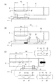
上記本発明の構成によれば、先ず、機械の加工範囲N内で、ワークW上の第1加工領域R1に対してV溝J1加工を行った後(図3(A)、図9のステップ101)、該ワークWを掴み替え(図3(B)、図9のステップ102)、その後、機械の加工範囲Nで、ワークW上の第2加工領域R2に対して第1加工領域R1のV溝J1に重ねてV溝J2を加工し(図3(C)⇒図4(A)、図9のステップ103)、以降、ワークW上の第n加工領域Rnまで、ワークWのワーク掴み替えと重ねV溝加工を繰り返すことにより(図9のステップ104)、第1加工領域R1から第n加工領域Rnに亘るV溝Tを加工することができる(図4(B)、図9のステップ105)。
According to the above-described configuration of the present invention, first, the V-groove J1 is machined in the first machining region R1 on the work W within the machining range N of the machine (FIG. 3(A), step in FIG. 9). 101), the work W is gripped again (FIG. 3(B),
よって、本発明によれば、ワークを掴み替えた後(図3(B))、該ワークの所定の加工領域を、機械の加工範囲内に順次進入させることにより(図3(C))、進入させた各加工領域におけるV溝加工を可能とし(図4(A))、V溝加工の拡大を図るようにした(図4(B))ワーク掴み替え切削加工方法を提供するという効果を奏する。 Therefore, according to the present invention, after re-grabbing the work (FIG. 3(B)), the predetermined working area of the work is sequentially advanced into the working range of the machine (FIG. 3(C)). An effect of providing a work grip re-grinding cutting method that enables V-groove processing in each of the entered processing regions (FIG. 4(A)) and expands V-groove processing (FIG. 4(B)) Play.
以下、本発明を、実施の形態により添付図面を参照して、説明する。
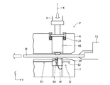
図1は本発明に係るワーク掴み替え切削加工方法に使用する切削加工用ダイDとそれと協働する切削加工用パンチPから成る金型の全体図である。
Hereinafter, the present invention will be described with reference to the accompanying drawings according to embodiments.
FIG. 1 is an overall view of a die including a cutting die D used in a work grip re-cutting method according to the present invention and a cutting punch P cooperating with the die.
図1の金型は、例えばタレットパンチプレス(図2)に適用され、上部フレーム1にはラムストライカー2が、上部タレット6には切削加工用パンチPが、下部タレット7には該切削加工用パンチPと協働する切削加工用ダイDがそれぞれ取り付けられている。
The die shown in FIG. 1 is applied to, for example, a turret punch press (FIG. 2). The
上部タレット6(図1)には、貫通孔45が形成され、該貫通孔45の上縁にはリフトスプリング31を介して前記切削加工用パンチPが支持されている。
A through
また、下部タレット7には、前記切削加工用ダイDが固定され、該切削加工用ダイDには、後述する本発明方法に使用される切削チップ50(図6、図7)が組み込まれている。
The cutting die D is fixed to the
上記切削チップ50は、その上にワークWを載置して移動させることにより、本発明方法のようなV溝加工が行われ(例えば図6)、所定の形状を有すると共に、タイプも片面タイプ等もあり、取り付け構造、冷却構造、切粉排出構造、更には上下動機構にもいろいろなものがあり、説明は省略する(特許文献1の図2〜図7)。
前記のとおり、図2においては、切削工具である切削チップ50を組み込んだ切削加工用ダイDによりV溝加工が行われる実施例を示したが、本発明はこれに限定されず、パンチP側に切削工具を組み込んだ場合でもよく、また、タレットパンチプレス(図2)におけるタレット6、7とは別位置に切削工具を組み込んだ場合でもよい。
The
As described above, FIG. 2 shows an example in which the V-groove processing is performed by the cutting die D incorporating the
図2は、本発明に係るワーク掴み替え切削加工方法が適用されるパンチプレスのうちのタレットパンチプレスを示す図であり、該タレットパンチプレスは、既述したように(図1)、上部タレット6と下部タレット7を有している。
FIG. 2 is a diagram showing a turret punch press of the punch presses to which the work grip re-cutting method according to the present invention is applied. As described above (FIG. 1), the turret punch press is an upper turret. 6 and a
この上部タレット6と下部タレット7には、切削加工用ダイD(図1)とそれと協働する切削加工用パンチPから成る金型、及びその他打ち抜き加工用、成型加工用等種々のパンチPとダイDから成る金型がそれぞれ同心円状に配置されている。
The
上記タレット6、7の回転機構は、次のとおりである。
即ち、上部タレット6の回転軸8と下部タレット7の回転軸9には、チェーン4と5がそれぞれ巻回されていると共に、該チェーン4と5は、駆動軸3に巻回されており、また、加工位置KにおけるパンチPの直上方であっで、上部フレーム1には、既述したように(図1)、例えば切削加工用パンチPを打圧して該パンチP全体を押し下げるラムストライカー2が設けられている。
The rotation mechanism of the
That is, the
この構成により、モータMにより駆動軸3を回転させることにより、チェーン4と5を循環させれば、上部タレット6と下部タレット7が同期回転し、所定のパンチPとダイDからなる金型、例えば本発明に係る切削加工用ダイD(図1)とそれと協働する切削加工用パンチPから成る金型などを加工位置Kにおいて選択することができる。
With this configuration, when the drive shaft 3 is rotated by the motor M and the
タレットパンチプレスの下部フレーム21(図2(B))上には、Y軸LMガイドレール17が敷設され、該Y軸LMガイドレール17には、サポートブラケット16が滑り結合しており、該サポートブラケット16を含むワーク位置決め装置は、次のとおりである。
A Y-axis
即ち、前記サポートブラケット16上には、キャリッジベース11が戴置されていると共に、該キャリッジベース11には、上部フレーム1に設けられたY軸モータMyのボールねじ14が螺合しており、また、キャリッジベース11には、ワークWを把持するクランプ13が取り付けられているキャリッジ12が、X軸LMガイドレール(図示省略)に滑り結合しており、該キャリッジ12には、X軸モータMx(図2(A))のボールねじ15が螺合している。
That is, the
更に、タレットパンチプレスの中央には、センタテーブル10が固定され、該センタテーブル10の両側には、サイドテーブル10A、10Bが配置され、該サイドテーブル10A、10Bは、前記サポートブラケット16に取り付けられている。
Further, a center table 10 is fixed to the center of the turret punch press, side tables 10A and 10B are arranged on both sides of the center table 10, and the side tables 10A and 10B are attached to the
この構成により、X軸モータMxを回転させると、キャリッジ12が、キャリッジベース11上をX軸方向に移動し、またY軸モータMyを回転させると、サポートブラケット16に支持されたキャリッジベース11が、サイドテーブル10A、10Bと共にY軸方向に移動する(図2(A))。
With this configuration, when the X-axis motor Mx is rotated, the
従って、切削加工用ダイD(図1)とそれと協働する切削加工用パンチPから成る金型を加工位置Kにおいて選択した状態で、キャリッジ12(図2)に搭載されたクランプ13に把持されたワークWを加工位置Kに位置決めし、そのままワークWを切削チップ50上で移動させれば、V溝加工等の切削加工を行うことができる。
Therefore, the die including the cutting die D (FIG. 1) and the cutting punch P cooperating therewith is selected at the processing position K and is held by the
ところが、既述したように(図10)、前記クランプ13を搭載したキャリッジ12の移動範囲(X軸方向)には、該キャリッジ12に螺合しているボールねじ15(図2(A))の長さ(X軸方向)に基づく制限があり、該ボールねじ15の長さを超えて、例えば左側には移動できず、具体的には、キャリッジ12(図10)は機械の加工範囲Nより左側へは移動できない。
However, as described above (FIG. 10), in the moving range (X-axis direction) of the
従って、ワークW上の第1加工領域R1に隣接する第2加工領域R2を、機械の加工範囲Nへ進入させることはできず、このため、第2加工領域R2でのV溝加工はできない。 Therefore, the second machining region R2 adjacent to the first machining region R1 on the work W cannot enter the machining range N of the machine, and therefore the V groove cannot be machined in the second machining region R2.
そのため、センタテーブル10(図2(A))には、吸着パッド等から成るワーク保持装置53を設け、後述するワーク掴み替え(図9のステップ102)を行うことにより、ワークを掴み替えた後該ワークの所定の加工領域を、機械の加工範囲内に順次進入させることにより、進入させた各加工領域におけるV溝加工を可能とし、V溝加工の拡大を図るようにした。
Therefore, the center table 10 (FIG. 2(A)) is provided with a
尚、公知のオートインデックス装置(金型回転機構)を設置すれば、片面タイプの切削チップ50(特許文献1の図2)を使用して所定の切削加工方法(特許文献1の図14)を実施する場合に、該切削チップ50の方向を自動的に変えることができるので、ワークWを行ったり帰ったりさせて往復状態で加工が可能となり、加工時間を短縮できるが、詳細な説明は省略する。
If a known auto index device (die rotating mechanism) is installed, a predetermined cutting method (FIG. 14 of Patent Document 1) is performed using a single-sided cutting tip 50 (FIG. 2 of Patent Document 1). When performing, the direction of the cutting
以下、本発明に係る切削加工方法を、図1〜図9に基づいて説明する。 Hereinafter, the cutting method according to the present invention will be described with reference to FIGS. 1 to 9.
(1)先ず、図9のステップ101において、機械の加工範囲N内で、第1加工領域R1に対してV溝J1加工を行う。
(1) First, in
この場合、機械の加工範囲Nとは、例えばタレットパンチプレス(図2)の加工位置Kを含む空間であって、切削加工用パンチPと切削加工用ダイDを使用して所定のV溝加工が行われる(図3(A)、図5)。 In this case, the processing range N of the machine is, for example, a space including the processing position K of the turret punch press (FIG. 2), and a predetermined V-groove processing is performed using the cutting punch P and the cutting die D. Is performed (FIG. 3(A), FIG. 5).
この場合のV溝加工は、図5に示すように、加工開始から終了まで例えば同じ切削チップ50を用い、加工開始時には、徐々に深くなるV溝g1を加工し、その後、一定の深さHのV溝Gを所定の長さL1だけ加工し、加工終了時には、徐々に浅くなるV溝g2を加工する。
In the V-groove processing in this case, as shown in FIG. 5, for example, the
この切削加工方法によれば、よく知られているように、切削チップ50が、いきなり一定の深さHのV溝を加工する場合に較べて、切削チップ50がワークWから受ける抵抗が少なくなり、これにより、切削チップの磨耗を防止することにより、寿命を長くした。
According to this cutting method, as is well known, the cutting
以後、本発明においては、前記機械の加工範囲N内では、既述したのと同じV溝加工が行われる(図3〜図4)。 Thereafter, in the present invention, the same V-groove processing as described above is performed within the processing range N of the machine (FIGS. 3 to 4).
また、第1加工領域R1(図3(A))とは、ワークW上のV溝が加工される領域であって、第2加工領域R2(図4(A))、・・・、及び第n加工領域Rn(図4(B))についても同様である。 The first processing region R1 (FIG. 3(A)) is a region where the V groove on the work W is processed, and the second processing region R2 (FIG. 4(A)),..., And The same applies to the nth processing region Rn (FIG. 4(B)).
そして、図9のステップ101においては、より詳しくは、機械の加工範囲N内で、ワークW上の第1加工領域R1に対してV溝J1加工を行い(図3(A))、このとき、ワークWはタレットパンチプレスのキャリッジベース11に移動自在に取り付けたキャリッジ12に搭載されたクランプ13に把持されている。
Then, in
また、前記V溝加工(図3(A))が行われる場合の切削加工用パンチPと切削加工用ダイDの動作は次のとおりである。 The operations of the cutting punch P and the cutting die D when the V groove processing (FIG. 3A) is performed are as follows.
即ち、図6に示すように、加工開始と同時に、例えばワークWを左側に移動すると共に、切削加工用パンチPを徐々に下降させることによりワークWに接触させ、切削加工用ダイD側の切削チップ50が徐々にワークWに食い込むようにする。
That is, as shown in FIG. 6, simultaneously with the start of machining, for example, the work W is moved to the left and the punch P for machining is gradually lowered to be brought into contact with the work W, thereby cutting on the die D for machining. The
これにより、加工開始時には、徐々に深くなるV溝g1が加工される。 As a result, at the start of processing, the V groove g1 that becomes gradually deeper is processed.
その後、切削加工用パンチPにより押圧されたワークWを同方向に移動させながら、前記図5に示すような一定の深さHのV溝Gを所定の長さL1だけ加工する。 After that, while moving the work W pressed by the punch P for cutting in the same direction, the V groove G having a constant depth H as shown in FIG. 5 is processed by a predetermined length L1.
そして、加工終了が近づくにつれて、切削加工用パンチP(図6)を徐々に上昇させてワークWから離せば、これにより、加工終了時には、徐々に浅くなるV溝g2が加工される。 Then, as the end of processing approaches, the punch P for cutting (FIG. 6) is gradually raised and separated from the work W, whereby the V groove g2 that becomes gradually shallower at the end of processing is processed.
このような切削加工用パンチPと切削加工用ダイDの動きにより、V溝加工(図3(A))における加工開始時のV溝g1と加工終了時のV溝g2が、極めてきれいに滑らかに加工される。 By such movements of the cutting punch P and the cutting die D, the V groove g1 at the start of processing and the V groove g2 at the end of processing in the V groove processing (FIG. 3A) are extremely clean and smooth. Is processed.
従って、V溝加工を重ねて行う場合でも(図3(C))、V溝g1とV溝g2の重なり部分が(参照符号Aの拡大図)きれいに加工され、第1加工領域R1から第n加工領域Rnに亘る一定の深さHで所定の長さLのV溝J(図8(C))が、ゆがむことなく真っ直ぐに形成される。 Therefore, even when the V-grooves are overlapped (FIG. 3C), the overlapping portion of the V-grooves g1 and g2 (enlarged view of reference numeral A) is neatly processed, and the first processed region R1 to the n-th region are processed. A V groove J (FIG. 8C) having a constant depth H and a predetermined length L over the processing region Rn is formed straight without distortion.
また、図7は、前記V溝加工(図3(A))が行われる場合の切削加工用パンチPと切削加工用ダイDの動作の他の実施形態を示し、図6と異なるのは、加工開始時には、切削加工用ダイDを徐々に上昇させ、加工終了時には、切削加工用ダイDを徐々に下降させる点にある Further, FIG. 7 shows another embodiment of the operation of the punch P for cutting and the die D for cutting when the V-groove processing (FIG. 3(A)) is performed, and differs from FIG. 6 in that At the start of processing, the cutting die D is gradually raised, and at the end of processing, the cutting die D is gradually lowered.
しかし、この図7の方法によっても、徐々に深くなるV溝g1(図3(A))と、徐々に浅くなるV溝g2が得られるのは、同じである。 However, it is the same that the method of FIG. 7 also provides the V groove g1 (FIG. 3A) that gradually becomes deeper and the V groove g2 that gradually becomes shallower.
(2)次に、図9のステップ102において、該ワークWを掴み替える。
(2) Next, in
即ち、既述した吸着パッド等のワーク保持装置53(図2)により、ワークW(図3(B))を保持した状態で、クランプ13をワークWから解放した後、該クランプ13を搭載したキャリッジ12を右側へ移動し、ワークWを把持することにより、ワークWを掴み替える。
That is, after holding the work W (FIG. 3B) by the work holding device 53 (FIG. 2) such as the suction pad described above, the
(3)その後、図9のステップ103おいて、機械の加工範囲N内で、第2加工領域R2に対して重ねてV溝J2加工を行う。
(3) Then, in
この場合、より詳しくは、機械の加工範囲N内で、ワークW上の第2加工領域R2に対して第1加工領域R1のV溝J1に重ねてV溝J2を加工するが、以下のような場合がある。 In this case, more specifically, within the machining range N of the machine, the V groove J2 is machined so as to overlap the V groove J1 of the first machining region R1 with respect to the second machining region R2 on the workpiece W. There is a case.
第1に、図3(C)における参照符号Aの拡大図に示すように、第2加工領域R2のV溝J2の加工開始時における徐々に深くなるV溝g1が終わる位置P1(深さH(図8(A)の下図)に到達する場合の左右方向(X軸方向)の位置)が、第1加工領域R1のV溝J1の加工終了時における徐々に浅くなるV溝g2が始まる位置P2と同位置の場合である。 First, as shown in an enlarged view of reference numeral A in FIG. 3C, a position P1 (depth H) at which the V groove g1 which becomes gradually deeper at the start of processing of the V groove J2 in the second processing region R2 ends. The position (the position in the left-right direction (X-axis direction) when reaching the lower part of FIG. 8A) is the position where the V groove g2 that becomes gradually shallower at the end of processing of the V groove J1 in the first processing region R1 starts. This is the case at the same position as P2.
第2に、図3(C)における下のカッコ内に示すように、第2加工領域R2のV溝J2の加工開始時における徐々に深くなるV溝g1が終わる位置P1(同様に、深さH(図8(A)の下図)に到達する場合の左右方向(X軸方向)の位置)が、第1加工領域R1のV溝J1の加工終了時における徐々に浅くなるV溝g2が始まる位置P2よりも左側(内側)の場合である。 Secondly, as shown in the lower parentheses in FIG. 3C, a position P1 at which the V-groove g1 that becomes gradually deeper at the start of machining of the V-groove J2 in the second machining region R2 ends (similarly to the depth The V groove g2, which becomes gradually shallower at the end of the machining of the V groove J1 in the first machining region R1, starts at the position H (the lower position in FIG. 8A) in the left-right direction (X-axis direction). This is the case on the left side (inside) of the position P2.
この場合、徐々に深くなるV溝g1が終わる位置P1と、徐々に浅くなるV溝g2が始まる位置P2との間は、実線で示されていて、切削加工が行われており、余裕を持たせてある。 In this case, between the position P1 where the V groove g1 which becomes gradually deeper ends and the position P2 where the V groove g2 which becomes gradually shallower starts are shown by a solid line, and cutting is performed, so that there is a margin. I have it.
第3に、図3(C)における上のカッコ内に示すように、第2加工領域R2のV溝J2の加工開始時における徐々に深くなるV溝g1が終わる位置P1(同様に、深さH(図8(A)の下図)に到達する場合の左右方向(X軸方向)の位置)が、第1加工領域R1のV溝J1の加工終了時における徐々に浅くなるV溝g2が始まる位置P2よりも右側(外側)の場合である。 Thirdly, as shown in the upper parentheses in FIG. 3C, a position P1 at which the V groove g1 that becomes gradually deeper at the start of processing of the V groove J2 of the second processing region R2 ends (also, the depth The V groove g2, which becomes gradually shallower at the end of the machining of the V groove J1 in the first machining region R1, starts at the position H (the lower position in FIG. 8A) in the left-right direction (X-axis direction). This is the case on the right side (outside) of the position P2.
この場合、徐々に深くなるV溝g1が終わる位置P1と、徐々に浅くなるV溝g2が始まる位置P2との間は、切削加工が行われておらず、削り残しが出てしまう。 In this case, cutting is not performed between the position P1 at which the gradually deepening V groove g1 ends and the position P2 at which the gradually shallowing V groove g2 starts, and uncut residue is left.
前記第1〜第3の重ね加工方法のうち、第1の加工(図3(C)における参照符号Aの拡大図)のようにP1をP2に対して同位置を狙うと、第3の加工(図3(C)における上のカッコ内)のようにP1がP2に対して右側にずれてしまった場合に、削り残しが出てしまう。 Among the first to third overlapping processing methods, if P1 is aimed at the same position with respect to P2 as in the first processing (enlarged view of reference numeral A in FIG. 3C), the third processing is performed. When P1 is displaced to the right with respect to P2 as in (inside the parentheses in FIG. 3C), the uncut portion is left.
そこで、このような事態を回避するために、前記第2の加工に示すように(図3(C)における下のカッコ内)、余裕を持たせた加工のプログラムを組むことが望ましい。 Therefore, in order to avoid such a situation, as shown in the second machining (inside the lower parentheses in FIG. 3C), it is desirable to prepare a machining program with a margin.
更に、第2加工領域R2のV溝J2を切削する場合の切削抵抗については、いきなり一定の深さHのV溝を加工する場合に較べてV溝J1の徐々に浅くなるV溝g1部分を、一定深さHのV溝へ切削していくために切削抵抗が少なくなり、これにより、切削チップ50の摩耗を防止し、寿命を長くした。
Further, regarding the cutting resistance when cutting the V groove J2 in the second processing region R2, the V groove g1 portion which becomes gradually shallower than the V groove J1 which is suddenly processed as compared with the case where the V groove having a constant depth H is suddenly processed. Since the V-groove having a constant depth H is cut, the cutting resistance is reduced, which prevents wear of the cutting
(4)その後、図9のステップ104において、ワークW上の第n加工領域Rnまで、前記(2)、(3)と同じ動作を繰り返す。
(4) Then, in
即ち、ワークWを加工する場合には、タレットパンチプレス(図2)の制御部(図示省略)を構成する例えば加工情報決定手段により、ワークW上のどの加工領域まで加工するかは、予め設定してある。 That is, when the work W is machined, which machining area on the work W is machined is set in advance by, for example, a machining information determining unit which constitutes a control unit (not shown) of the turret punch press (FIG. 2). I am doing it.
従って、例えば予め第5加工領域R5まで加工するということが設定されていれば、本発明においては、第2加工領域R2から第5加工領域R5まで、ワークWの掴み替えと重ねV溝加工(図9のステップ102と103)を繰り返し、一般には、第n加工領域Rn(図4(B))まで同じ動作を繰り返す。
Therefore, for example, if it is set in advance to machine up to the fifth machining region R5, in the present invention, re-grasping of the workpiece W and overlapping V groove machining (from the second machining region R2 to the fifth machining region R5).
(5)最後に、図9のステップ105において、第1加工領域R1から第n加工領域Rnに亘るV溝Tを加工する(図4(B))。
(5) Finally, in
より具体的には、第1加工領域R1から第n加工領域Rnに亘る一定の深さHで所定の長さLのV溝Jを有する全体のV溝Tを加工する(図8(A)(上図は裏面図、下図は側面図))。 More specifically, the entire V-groove T having the V-groove J having a constant depth H and a predetermined length L from the first processing region R1 to the n-th processing region Rn is processed (FIG. 8A). (Upper figure is back view, lower figure is side view).
即ち、左端に徐々に深くなるV溝、右端に徐々に浅くなるV溝があり、途中だけ一定の深さHで所定の長さLのV溝Jを有する全体のV溝Tを加工する。 That is, there is a V groove that gradually becomes deeper at the left end and a V groove that gradually becomes shallower at the right end, and the entire V groove T having a V groove J having a predetermined depth L and a constant depth H is machined midway.
しかし、全体のV溝Tの両端の前記徐々に深くなるV溝g1と、徐々に浅くなるV溝g2を含むワークW部分W1、W2は、通常は製品としての価値は無い。 However, the work W portions W1 and W2 including the gradually deepening V groove g1 and the gradually shallower V groove g2 at both ends of the entire V groove T are usually not valuable as products.
よって、V溝加工が終了した場合(図8(A)、図9のステップ106のYES)、即ち、最後の第n加工領域Rnまで加工が終了した場合には、前記製品として不要な両端のワークW部分W1、W2は切断し(図4(C)、図8(B)、図9のステップ107)、上記一定の深さHで所定の長さLのV溝Jが加工されたワークW部分のみを製品として残す。
Therefore, when the V-groove processing is completed (FIG. 8A, YES in
上記したように、最後の第n加工領域Rnまで加工が終了した場合には、前記製品として不要な両端のワークW部分W1、W2を切断する旨について言及したが(図4(C)、図8(B)、図9のステップ107)、このように不要なワークW部分W1、W2を一挙に切断するのではなく、例えば第1加工領域R1(図8(A))におけるV溝J1加工終了後に、予め不要なワーク部分W1を切断してもよい。
As described above, when the processing is completed up to the last n-th processing area Rn, it is mentioned that the workpiece W portions W1 and W2 at both ends which are unnecessary as the product are cut (FIG. 4(C), FIG. 8(B),
次に、本発明方法の応用例について図10〜図15を用いて説明する。 Next, application examples of the method of the present invention will be described with reference to FIGS.
始めに、本応用例を説明する前提として、タレットパンチプレスによるV溝加工における端部加工速度によるV溝の仕上がりの違いについて図11を参照しながら説明する。ここで、以下の説明における端部加工速度とは、徐々に深くなるV溝g1或いは徐々に浅くなるV溝g2の加工時において、ワークWのX方向の単位移動量に対するパンチPのZ方向の移動量のことを言う。端部加工速度は、ワークWのX方向の送り速度とラムストライカー2(切削加工用パンチP)のZ方向の送り速度を制御することで調整することができる。この端部加工速度が遅い場合、V溝g1の長さLg1s或いはg2の長さLg2sは長くなり、加工されるV溝Jの始端或いは終端はなだらか延びるV字状に仕上がる(図10(A))。一方、端部加工速度が速い場合、V溝g1の長さLg1f或いはV溝g2の長さLg2fは短くなり(Lg1f<Lg1s、Lg2f<Lg2s)、加工されるV溝Jの始端或いは終端は急峻に狭まるV字状に仕上がる(図10(B))。 First, as a premise for explaining this application example, the difference in the finish of the V groove depending on the end processing speed in the V groove processing by the turret punch press will be described with reference to FIG. 11. Here, the edge processing speed in the following description means the Z direction of the punch P with respect to the unit movement amount of the workpiece W in the X direction when processing the V groove g1 that gradually becomes deeper or the V groove g2 that gradually becomes shallower. It refers to the amount of movement. The edge processing speed can be adjusted by controlling the X-direction feed speed of the work W and the Z-direction feed speed of the ram striker 2 (cutting punch P). When the processing speed of the end portion is slow, the length Lg1s of the V groove g1 or the length Lg2s of the g2 becomes long, and the start end or the end of the V groove J to be processed is finished in a V shape that gently extends (FIG. 10(A)). ). On the other hand, when the end processing speed is fast, the length Lg1f of the V groove g1 or the length Lg2f of the V groove g2 becomes short (Lg1f<Lg1s, Lg2f<Lg2s), and the start end or the end of the V groove J to be processed is steep. It is finished in a V shape that narrows (Fig. 10(B)).
続いて、本発明方法に適切な端部加工速度について説明する。
ここで、仮に図9のステップ107に着目すると、図4(C)に示すように、V溝Jの不要な両端のワークW部分W1及びW2が短い方が望ましい。従って、この点のみを考慮すると、より速い端部加工速度によってV溝g1及びg2を加工する方が良いと言える。しかし、本発明方法において、単純に速い端部加工速度を用いると次のような問題が生じ得る。
Next, the edge processing speed suitable for the method of the present invention will be described.
Here, if attention is paid to step 107 in FIG. 9, it is desirable that the work W portions W1 and W2 at both ends of the V groove J which are not required are shorter, as shown in FIG. 4C. Therefore, considering only this point, it can be said that it is better to process the V grooves g1 and g2 at a higher edge processing speed. However, in the method of the present invention, the following problems may occur when simply using a high edge machining speed.
図2のタレットパンチプレスは、X方向に並ぶ2つのクランプ13を有しており、これらによってワークWの一方側を掴んでワークWを固定する。そのため、クランプ13の配列方向、つまりX方向に延びるV溝Jを加工する際、図11(A)の紙面左側にワークWを移動させると(図11(A)の墨付矢印)、ワークWには切削チップ50の抵抗によって切削チップ50を支点とする時計回りの回転モーメントが生じてしまう(図11(A)の白抜き矢印)。そして、この回転モーメントが大きくなると、V溝JがX方向に対して歪んでしまい、始端と終端のY方向の位置にずれdyが生じてしまう(図11(B))。
The turret punch press in FIG. 2 has two
なお、クランプ13の配列方向と直交する方向、つまりY方向に延びるV溝Jを加工する場合、例えば、図12の紙面上側にワークWを移動させることになる(図12の墨付矢印)。そのため、V溝Jcのように、ワークWのうちX方向のクランプ13間にV溝を加工する場合、ワークWには回転モーメントは生じない。一方、V溝Jsのように、ワークWのうちX方向のクランプ13間の外にV溝を加工する場合、ワークWには多少の回転モーメントは生じると考えられる。但し、本発明方法では、V溝JをいずれもX方向に加工するため、V溝JをY方向に加工する場合については考慮しなくても良い。
When processing the V groove J extending in the direction orthogonal to the arrangement direction of the
本発明方法では、加工領域毎にX方向に延びるV溝Jを加工し、これの繰り返しによってX方向に長く延びるV溝Tを形成する。そのため、加工後のV溝Tには、各V溝Jの歪みの影響が出てしまう。具体的には、形成されるV溝Tを極端に表現すると、図13に示すように、隣り合うV溝Jの重なり部分においてY方向に多少の段差が生じる場合がある(図13の破線a101)。特に、速い端部加工速度を用いた場合、図14に示すように、破線a101で囲まれたV溝Jの重なり部分において、急峻に狭まるV字状のV溝g1及びg2が合わさることになるため、上記段差はより目立つようになってしまう。 In the method of the present invention, the V groove J extending in the X direction is processed for each processing region, and the V groove T extending in the X direction is formed by repeating the processing. Therefore, the V-shaped groove T after processing is affected by the distortion of each V-shaped groove J. Specifically, when the V groove T to be formed is extremely expressed, as shown in FIG. 13, a slight step may occur in the Y direction at the overlapping portion of the adjacent V grooves J (broken line a101 in FIG. 13). ). In particular, when a high end machining speed is used, as shown in FIG. 14, the V-shaped V grooves g1 and g2 that are sharply narrowed are combined at the overlapping portion of the V grooves J surrounded by the broken line a101. Therefore, the step becomes more conspicuous.
そこで、本応用例では、端部加工速度を切り替えながらV溝Tを形成する。
具体的には、図15に示すように、V溝g1及びg2のうち、V溝Tの始端に当る第1加工領域R1のV溝g1を「g1´」とし、V溝Tの終端に当る第n加工領域RnのV溝g2を「g2´」とした場合、V溝g1´及びg2´を比較的速い端部加工速度で加工し(図15中の破線a102)、その他のV溝g1及びg2を、V溝g1´及びg2´の加工時よりも遅い端部加工速度で加工する(図15中の破線a103及びa104)。つまり、V溝g1´及びg2´の長さLg1´及びLg2´は短く加工し、その他のV溝g1及びg2の長さLg1及びLg2を長くする。
Therefore, in this application example, the V groove T is formed while switching the end processing speed.
Specifically, as shown in FIG. 15, of the V-grooves g1 and g2, the V-groove g1 of the first processing region R1 which is the start end of the V-groove T is “g1′” and is the end of the V-groove T. When the V groove g2 of the nth processing region Rn is set to "g2'", the V grooves g1' and g2' are processed at a relatively high end processing speed (broken line a102 in FIG. 15), and the other V grooves g1. And g2 are processed at the end part processing speed slower than that at the time of processing the V grooves g1′ and g2′ (broken lines a103 and a104 in FIG. 15). That is, the lengths Lg1′ and Lg2′ of the V grooves g1′ and g2′ are processed to be short, and the lengths Lg1 and Lg2 of the other V grooves g1 and g2 are lengthened.
この場合、V溝Tの中間部では、V溝g1及びg2が比較的なだらかなV字状に加工されるため、隣り合うV溝g2とV溝g1を良くなじませることができる。その結果、V溝Jの重なり部分の段差が目立たず、始端から終端まで滑らかに延びるV溝Tを形成することができる。一方、V溝Tの両端部に当るV溝g1´及びg2´は速い端部加工速度で加工されるため、それらは短くなり、製品としての価値が無いワークW部分W1及びW2の増大が抑制される。 In this case, in the middle portion of the V groove T, the V grooves g1 and g2 are processed into a comparatively gentle V shape, so that the adjacent V groove g2 and V groove g1 can be fit well. As a result, the step of the overlapping portion of the V groove J is not conspicuous, and the V groove T that smoothly extends from the start end to the end can be formed. On the other hand, since the V grooves g1′ and g2′ that come into contact with both ends of the V groove T are processed at a high end processing speed, they are shortened and the increase of the work W portions W1 and W2, which have no value as a product, is suppressed. To be done.
つまり、本応用例によれば、ワーク部分W部分W1及びW2の増大を抑制しつつ、より滑らかで段差の少ないV溝Tを形成することが可能となる。 That is, according to this application example, it is possible to form the V groove T that is smoother and has less steps while suppressing an increase in the work portions W portions W1 and W2.
本発明は、ワークを掴み替えた後、該ワークの所定の加工領域を、機械の加工範囲内に順次進入させることにより、進入させた各加工領域におけるV溝加工を可能とし、V溝加工の拡大を図るようにしたワーク掴み替え切削加工方法に利用され、更に、一対の金型が配置されたシングルパンチプレスのみならず複数対の金型が配置された上部タレットと下部タレットを有するタレットパンチプレスにも適用され、極めて有用である。 The present invention makes it possible to perform V-groove processing in each of the entered processing areas by sequentially advancing a predetermined processing area of the work into the processing range of the machine after re-grabbing the work. A turret punch having an upper turret and a lower turret in which a plurality of pairs of dies are arranged, as well as a single punch press in which a pair of dies is arranged, which is used for a work piece re-gripping cutting method designed to be enlarged. It is also applied to presses and is extremely useful.
1 上部フレーム
2 ラムストライカー
6 上部タレット
7 下部タレット
13 クランプ
21 下部フレーム
31 リフトスプリング
39 排出孔
45 貫通孔
41 ダイ本体
50 切削チップ
51 冷却機構
52 排出機構
53 ワーク保持装置
D 切削加工用ダイ
P 切削加工用パンチ
W ワーク
W´ 切粉
1
Claims (7)
(1)前記パンチプレスのクランプによってワークが把持された状態において、該ワーク上の一部の加工領域を機械の加工範囲内に進入させることで、該加工領域に対してV溝加工を行った後、
(2)V溝を加工した加工領域に対して該V溝の延在方向に隣接する次の加工領域が前記機械の加工範囲に進入可能となるよう、該ワークを掴み替えることで前記クランプによる前記ワークの把持位置を変更し、
(3)その後、該ワークの前記次の加工領域を前記機械の加工範囲内に進入させることで、該次の加工領域のV溝の始まる位置が前の加工領域のV溝の終わる位置に重なるように、該次の加工領域に対して前記前の加工領域のV溝の延在方向に連続するV溝を加工し、
(4)ワーク上の第n加工領域まで、前記(2)、(3)と同じ動作を繰り返し、
(5)前記(1)の加工領域から第n加工領域に亘る長さを有するV溝を加工することを特徴とするワーク掴み替え切削加工方法。 A cutting method in a punch press for performing V-groove processing by cutting using a die including a cutting die equipped with a cutting tip and a punch for cooperating with the die .
(1) In a state where the workpiece by the clamp of the punch press is gripped, by entering a part of the working area on the workpiece in the machining area of the machine, was V groove processing with respect to the machining area rear,
(2) so that the next machining area a V-groove with respect to processed processing area adjacent to the extending direction of said V-groove is possible enter the machining area of the machine, the clamp with gripping sort Rukoto the workpiece Change the gripping position of the work by
(3) After that, the position where the V groove of the next processing region starts overlaps with the position where the V groove of the previous processing region ends by causing the next processing region of the workpiece to enter the processing range of the machine. As described above, a V-groove that is continuous in the extending direction of the V-groove of the previous processing region is processed with respect to the next processing region ,
(4) The same operations as (2) and (3) above are repeated until the n-th processing area on the work,
(5) Work gripping sort cutting method characterized by machining a V-groove that have a Wataru Ru length from the machining region to the n processing region of (1).
ことを特徴とする請求項2又は3記載のワーク掴み替え切削加工方法。 The gradually deepening V-groove of the preceding processing region and the gradually deepening V-groove other than the end processing speed of the gradually shallowing V-groove of the n-th processing region, and the other The method for re-gripping a workpiece according to claim 2 or 3, wherein the processing speed of the end portion of the V groove which becomes gradually shallower is decreased.
前記パンチプレスは、前記V溝を前記第1方向に加工する
ことを特徴とする請求項6記載のワーク掴み替え切削加工方法。 The clamp has a plurality arranged in a first direction,
The said punch press processes the said V groove in the said 1st direction. The workpiece re-gripping cutting processing method of Claim 6 characterized by the above-mentioned.
Applications Claiming Priority (2)
| Application Number | Priority Date | Filing Date | Title |
|---|---|---|---|
| JP2015150471 | 2015-07-30 | ||
| JP2015150471 | 2015-07-30 |
Publications (2)
| Publication Number | Publication Date |
|---|---|
| JP2017030142A JP2017030142A (en) | 2017-02-09 |
| JP6718329B2 true JP6718329B2 (en) | 2020-07-08 |
Family
ID=57986551
Family Applications (1)
| Application Number | Title | Priority Date | Filing Date |
|---|---|---|---|
| JP2016142744A Active JP6718329B2 (en) | 2015-07-30 | 2016-07-20 | Work grip replacement cutting method |
Country Status (1)
| Country | Link |
|---|---|
| JP (1) | JP6718329B2 (en) |
Family Cites Families (5)
| Publication number | Priority date | Publication date | Assignee | Title |
|---|---|---|---|---|
| GB2206513B (en) * | 1987-07-08 | 1991-11-06 | Amada Co Ltd | V-shaped groove forming machine and its control method |
| JP2677819B2 (en) * | 1988-06-14 | 1997-11-17 | 株式会社アマダ | V-shaped grooving machine |
| JP3269450B2 (en) * | 1998-03-10 | 2002-03-25 | 村田機械株式会社 | Automatic programming device for multi-task machines |
| JP5525849B2 (en) * | 2010-02-10 | 2014-06-18 | 株式会社アマダ | Safe operation method of plate processing machine with numerical controller |
| JP6060433B2 (en) * | 2013-03-08 | 2017-01-18 | 株式会社アマダホールディングス | Cutting die and cutting method |
-
2016
- 2016-07-20 JP JP2016142744A patent/JP6718329B2/en active Active
Also Published As
| Publication number | Publication date |
|---|---|
| JP2017030142A (en) | 2017-02-09 |
Similar Documents
| Publication | Publication Date | Title |
|---|---|---|
| WO1997018909A1 (en) | Punching machine and punching method | |
| JP2004291065A (en) | Method and apparatus for incremental forming | |
| JP6718329B2 (en) | Work grip replacement cutting method | |
| JP4513995B2 (en) | Turret punch press and processing method using the turret punch press | |
| JP6055620B2 (en) | Automatic programming apparatus and method and machining system | |
| KR20200025029A (en) | Deburring apparatus for auto transmisson shift pipe | |
| JP4955489B2 (en) | Bending machine | |
| JP3792831B2 (en) | Plate material processing method and composite processing machine in composite processing line | |
| JP4556676B2 (en) | The second relief part processing method of the punching die of the press die | |
| JP2018089632A (en) | Countersunk hole forming method and press machine | |
| TWI571338B (en) | Electrical discharge machine equipped with trimming tools | |
| JP4573390B2 (en) | Work positioning method | |
| JP2007105864A (en) | Method and apparatus for lathe turning | |
| JP2018192486A (en) | Punch press and cutting method | |
| JP2018167313A (en) | Chamfering method, and die | |
| JP2013020436A (en) | Machining device and machining method | |
| JP5603206B2 (en) | Workpiece machining method, workpiece machining apparatus, and program | |
| JP6568970B2 (en) | Cutting tool | |
| JP3768620B2 (en) | Plate processing method | |
| JP6877274B2 (en) | How to form punch presses and tapered female threads | |
| JP2000301261A (en) | Turret punch press | |
| JP6132732B2 (en) | Processing apparatus and method of moving tool | |
| JP6330017B1 (en) | Workpiece processing method by punch / laser combined processing machine and punch / laser combined processing machine | |
| JP2024022154A (en) | External gear processing method using skiving cutter | |
| JP2002066652A (en) | Die for punch press and working method in punch press |
Legal Events
| Date | Code | Title | Description |
|---|---|---|---|
| A621 | Written request for application examination |
Free format text: JAPANESE INTERMEDIATE CODE: A621 Effective date: 20190409 |
|
| A977 | Report on retrieval |
Free format text: JAPANESE INTERMEDIATE CODE: A971007 Effective date: 20200206 |
|
| A131 | Notification of reasons for refusal |
Free format text: JAPANESE INTERMEDIATE CODE: A131 Effective date: 20200310 |
|
| A521 | Written amendment |
Free format text: JAPANESE INTERMEDIATE CODE: A523 Effective date: 20200501 |
|
| TRDD | Decision of grant or rejection written | ||
| A01 | Written decision to grant a patent or to grant a registration (utility model) |
Free format text: JAPANESE INTERMEDIATE CODE: A01 Effective date: 20200526 |
|
| A61 | First payment of annual fees (during grant procedure) |
Free format text: JAPANESE INTERMEDIATE CODE: A61 Effective date: 20200612 |
|
| R150 | Certificate of patent or registration of utility model |
Ref document number: 6718329 Country of ref document: JP Free format text: JAPANESE INTERMEDIATE CODE: R150 |