JP6714815B2 - Drive device and robot - Google Patents

Drive device and robot Download PDF

Info

Publication number
JP6714815B2
JP6714815B2 JP2016000887A JP2016000887A JP6714815B2 JP 6714815 B2 JP6714815 B2 JP 6714815B2 JP 2016000887 A JP2016000887 A JP 2016000887A JP 2016000887 A JP2016000887 A JP 2016000887A JP 6714815 B2 JP6714815 B2 JP 6714815B2
Authority
JP
Japan
Prior art keywords
unit
arm
piezoelectric actuator
signal
obstacle
Prior art date
Legal status (The legal status is an assumption and is not a legal conclusion. Google has not performed a legal analysis and makes no representation as to the accuracy of the status listed.)
Active
Application number
JP2016000887A
Other languages
Japanese (ja)
Other versions
JP2017123715A5 (en
JP2017123715A (en
Inventor
宮澤 修
修 宮澤
Current Assignee (The listed assignees may be inaccurate. Google has not performed a legal analysis and makes no representation or warranty as to the accuracy of the list.)
Seiko Epson Corp
Original Assignee
Seiko Epson Corp
Priority date (The priority date is an assumption and is not a legal conclusion. Google has not performed a legal analysis and makes no representation as to the accuracy of the date listed.)
Filing date
Publication date
Application filed by Seiko Epson Corp filed Critical Seiko Epson Corp
Priority to JP2016000887A priority Critical patent/JP6714815B2/en
Publication of JP2017123715A publication Critical patent/JP2017123715A/en
Publication of JP2017123715A5 publication Critical patent/JP2017123715A5/ja
Application granted granted Critical
Publication of JP6714815B2 publication Critical patent/JP6714815B2/en
Active legal-status Critical Current
Anticipated expiration legal-status Critical

Links

Images

Description

本発明は、駆動装置、およびこれを備えるロボットに関する。 The present invention relates to a drive device and a robot including the drive device.

従来、移動体の進行する方向に位置する障害物を検知し、その検知結果によって当該障害物を回避する障害物検知装置が知られている。例えば、特許文献1には、走行車体の駆動輪を駆動する駆動モーター(駆動装置)と、当該車体の外周に設けられている複数の送信用超音波センサーと、送信用超音波センサーと交互に配置された複数の受信用超音波センサーとを備えた障害物検知装置が開示されている。 BACKGROUND ART Conventionally, an obstacle detection device is known that detects an obstacle located in a traveling direction of a moving body and avoids the obstacle based on the detection result. For example, in Patent Document 1, a drive motor (driving device) for driving the drive wheels of a traveling vehicle body, a plurality of transmission ultrasonic sensors provided on the outer periphery of the vehicle body, and a transmission ultrasonic sensor are alternately provided. An obstacle detection device including a plurality of receiving ultrasonic sensors arranged is disclosed.

特開2003−35774号公報JP, 2003-35774, A

しかしながら、上述の特許文献1における障害物検知装置の場合、駆動装置としての駆動モーターに加えて、超音波を発信する送信用超音波センサーが別途設けられている構成であるため、装置の小型化・軽量化が困難であるという課題を有していた。 However, in the case of the obstacle detection device in Patent Document 1 described above, in addition to the drive motor as the drive device, a transmission ultrasonic sensor for transmitting ultrasonic waves is separately provided, and thus the device is downsized.・There was a problem that it was difficult to reduce the weight.

本発明は、上述の課題の少なくとも一部を解決するためになされたものであり、以下の形態または適用例として実現することが可能である。 The present invention has been made to solve at least a part of the problems described above, and can be realized as the following modes or application examples.

[適用例1]本適用例に係る駆動装置は、振動部を有する圧電アクチュエーターを備えている駆動部と、前記駆動部からの駆動力により前記駆動部に対して相対的に移動する被駆動部と、前記振動部から発信される超音波信号を受信する受信部と、前記受信部からの出力信号により障害物の有無を判断する判断部と、を備えていることを特徴とする。 Application Example 1 A drive device according to this application example includes a drive unit including a piezoelectric actuator having an oscillating unit, and a driven unit that is moved relative to the drive unit by a drive force from the drive unit. And a receiving unit that receives the ultrasonic signal transmitted from the vibrating unit, and a determining unit that determines the presence or absence of an obstacle based on the output signal from the receiving unit.

本適用例によれば、駆動部に備えられた圧電アクチュエーターの振動部から超音波信号が発信され、受信された超音波信号に基づいて受信部から出力された出力信号により判断部が障害物の有無を判断する。このように、被駆動部を移動させる駆動部には超音波信号を発信する振動部が備えられている。換言すれば、駆動部と超音波信号を発信する振動部とが一体的に構成されているため、駆動装置の小型化・軽量化を実現することができる。 According to this application example, an ultrasonic signal is transmitted from the vibrating portion of the piezoelectric actuator provided in the drive unit, and the determination unit determines whether the obstacle is an obstacle based on the output signal output from the receiving unit based on the received ultrasonic signal. Determine the presence or absence. As described above, the driving unit that moves the driven unit is provided with the vibrating unit that transmits the ultrasonic signal. In other words, since the drive unit and the vibration unit that transmits an ultrasonic signal are integrally configured, the drive device can be made smaller and lighter.

[適用例2]上記適用例に記載の駆動装置において、前記受信部で受信した前記超音波信号の状態を記憶する記憶部を備え前記記憶部は、前記障害物の無い場合に受信した前記超音波信号を、基準超音波信号として記憶し、前記判断部は、前記記憶部に記憶されている前記基準超音波信号の状態と、前記被駆動部の移動中に前記受信部が受信した前記超音波信号に基づく前記受信部からの出力信号の状態とに変化を生じた場合に、前記障害物が存在すると判断し、判断信号を出力することが好ましい。 Application Example 2 In the drive device described in the above application example, a storage unit that stores the state of the ultrasonic signal received by the reception unit is provided, and the storage unit includes the storage unit that receives the ultrasonic signal when there is no obstacle. The ultrasonic wave signal is stored as a reference ultrasonic wave signal, and the determination unit determines the state of the reference ultrasonic wave signal stored in the storage unit and the ultrasonic wave received by the reception unit during movement of the driven unit. It is preferable that when the state of the output signal from the receiving unit based on the sound wave signal changes, it is determined that the obstacle exists and the determination signal is output.

本適用例によれば、記憶部に記憶されている障害物の無い場合の超音波信号である基準超音波信号の状態と、被駆動部の移動中に受信部から出力される超音波信号の状態との変化によって障害物が存在すると判断し、判断信号を出力する。このように、簡便な方法によって、容易に障害物の有無を判断することができる。 According to this application example, the state of the reference ultrasonic signal, which is the ultrasonic signal when there is no obstacle stored in the storage unit, and the ultrasonic signal output from the receiving unit while the driven unit is moving. It judges that there is an obstacle based on the change in the state and outputs a judgment signal. In this way, the presence/absence of an obstacle can be easily determined by a simple method.

[適用例3]上記適用例に記載の駆動装置において、前記圧電アクチュエーターへ供給する電力を制御する電力制御部を備え、前記電力制御部は、前記判断部から出力された前記判断信号により、前記圧電アクチュエーターへ供給する電力を制御することが好ましい。 Application Example 3 In the drive device according to the application example described above, a power control unit that controls the power supplied to the piezoelectric actuator is provided, and the power control unit uses the determination signal output from the determination unit, It is preferable to control the power supplied to the piezoelectric actuator.

本適用例によれば、判断部から出力された判断信号によって電力制御部が圧電アクチュエーターへ供給する電力を制御することにより、駆動部(被駆動部)の駆動状態を容易に制御することができる。 According to this application example, the drive state of the drive unit (driven unit) can be easily controlled by controlling the power supplied to the piezoelectric actuator by the power control unit according to the determination signal output from the determination unit. ..

[適用例4]上記適用例に記載の駆動装置において、前記圧電アクチュエーターは、複数配置されていることが好ましい。 Application Example 4 In the drive device described in the above application example, it is preferable that a plurality of the piezoelectric actuators are arranged.

本適用例によれば、複数の圧電アクチュエーターが、円周状に配置され、それぞれの圧電アクチュエーターから超音波信号が発信される。これにより、障害物の存在する位置(方向)を精度よく検知することができる。 According to this application example, the plurality of piezoelectric actuators are circumferentially arranged, and ultrasonic signals are transmitted from the respective piezoelectric actuators. Thereby, the position (direction) where the obstacle exists can be detected with high accuracy.

[適用例5]本適用例に係るロボットは、支持部と、前記支持部に接続されている関節部と、前記支持部に前記関節部を介して接続され、前記支持部に対して相対移動可能な第1アームと、適用例1ないし適用例4のいずれか一項に記載の駆動装置と、を備え、前記関節部に、前記駆動装置の前記圧電アクチュエーターが備えられていることを特徴とする。 Application Example 5 A robot according to this application example includes a support section, a joint section connected to the support section, a joint section connected to the support section via the joint section, and a relative movement with respect to the support section. A possible first arm and the drive device according to any one of Application Examples 1 to 4, wherein the joint section is provided with the piezoelectric actuator of the drive device. To do.

本適用例によれば関節部に、駆動装置の圧電アクチュエーターが備えられていることにより、関節部を介して移動する第1アームを備えたロボットを大型化することなく実現することができる。 According to this application example, since the joint portion is provided with the piezoelectric actuator of the driving device, the robot including the first arm that moves through the joint portion can be realized without increasing the size.

[適用例6]上記適用例に記載のロボットにおいて、第2アームを備え、前記第2アームは、前記支持部と前記第1アームとの間に位置し、前記支持部および前記第1アームのそれぞれと、前記関節部を介して接続されていることが好ましい。 Application Example 6 In the robot described in the above application example, a second arm is provided, the second arm is located between the support portion and the first arm, and the second arm is provided between the support portion and the first arm. It is preferable that they are connected to each other via the joint portion.

本適用例によれば、複数の関節部を備えており、それぞれに超音波信号の発信源を兼ねる圧電アクチュエーター(振動部)を有していることから、複数位置を起点として複数方向の障害物の検知を行うことができる。 According to this application example, a plurality of joint portions are provided, and each of them has a piezoelectric actuator (vibrating portion) that also serves as a source of an ultrasonic signal. Can be detected.

[適用例7]上記適用例に記載のロボットにおいて、前記圧電アクチュエーターよりも先端側に位置する前記第1アームに、前記駆動装置の前記受信部が設けられていることが好ましい。 Application Example 7 In the robot described in the above application example, it is preferable that the first arm located closer to the tip end side than the piezoelectric actuator is provided with the receiving portion of the drive device.

本適用例によれば、圧電アクチュエーターよりも先端側に位置する第1アームに受信部が設けられていることから、第1アームの可動範囲内の障害物に近い位置で超音波信号を受信することができる。これにより、障害物の有無による超音波信号の変化を、より精度よく検知することができる。 According to this application example, since the receiving unit is provided in the first arm located closer to the tip end than the piezoelectric actuator, the ultrasonic signal is received at a position near the obstacle within the movable range of the first arm. be able to. This makes it possible to more accurately detect a change in the ultrasonic signal due to the presence or absence of an obstacle.

[適用例8]上記適用例に記載のロボットにおいて、アーム制御部を備え、前記アーム制御部は、前記第1アームの可動範囲内に前記障害物が有ると前記駆動装置の前記判断部が判断したときに、前記第1アームと前記障害物との衝突を回避するための制御を行うことが好ましい。 Application Example 8 In the robot according to the application example described above, an arm control unit is provided, and the arm control unit determines by the determination unit of the drive device that the obstacle is within the movable range of the first arm. When doing so, it is preferable to perform control for avoiding a collision between the first arm and the obstacle.

本適用例によれば、駆動装置の判断部の判断に基づくアーム制御部の制御により、第1アームの可動範囲内に障害物が有る場合は、第1アームと障害物との衝突を回避することができる。 According to this application example, when the obstacle is within the movable range of the first arm, the collision between the first arm and the obstacle is avoided by the control of the arm control unit based on the determination of the determination unit of the drive device. be able to.

第1実施形態に係る駆動装置の概略を示す説明図。Explanatory drawing which shows the outline of the drive device which concerns on 1st Embodiment. 圧電アクチュエーターの一例を示す概略平面図。FIG. 3 is a schematic plan view showing an example of a piezoelectric actuator. 圧電アクチュエーターの一例を示す概略平面図。FIG. 3 is a schematic plan view showing an example of a piezoelectric actuator. 圧電アクチュエーターの動作を示す説明図。Explanatory drawing which shows operation|movement of a piezoelectric actuator. 圧電アクチュエーターの動作を示す説明図。Explanatory drawing which shows operation|movement of a piezoelectric actuator. 圧電アクチュエーターの駆動波形および超音波信号波形の一例を示す説明図。Explanatory drawing which shows an example of a drive waveform and an ultrasonic signal waveform of a piezoelectric actuator. 第1実施形態に係る駆動装置の障害物の検出手順を示すフローチャート。3 is a flowchart showing an obstacle detection procedure of the drive device according to the first embodiment. 第2実施形態に係る駆動装置の概略を示す平面図。The top view which shows the outline of the drive device which concerns on 2nd Embodiment. 図6Aに示すP視からの側面図。The side view from the P view shown in FIG. 6A. 第3実施形態に係る圧電モーターの動作を示す説明図。Explanatory drawing which shows operation|movement of the piezoelectric motor which concerns on 3rd Embodiment. 圧電アクチュエーターを用いたロボットの一実施形態としてロボットアームを有するロボットを示す説明図。Explanatory drawing which shows the robot which has a robot arm as one Embodiment of the robot which uses a piezoelectric actuator. エンドエフェクターが取り付けられたロボットアームの手首部分を拡大して示す説明図。Explanatory drawing which expands and shows the wrist part of the robot arm to which the end effector was attached.

(第1実施形態)
以下、本発明の第1実施形態に係る駆動装置を、図1〜図5を参照して説明する。図1は、第1実施形態に係る駆動装置の概略を示す説明図である。図1に示す駆動装置10は、駆動部20と、被駆動部30と、受信部としての超音波受信部40と、制御部50と、を備えている。なお、図1において、駆動部20と被駆動部30との配置関係を示すため、図1紙面の左右方向をX方向、紙面の上下方向をY方向、紙面に垂直方向をZ方向とする。これらの方向は、図2A、図2B、図3A、および図3Bも同様である。
(First embodiment)
Hereinafter, the driving device according to the first embodiment of the present invention will be described with reference to FIGS. 1 to 5. FIG. 1 is an explanatory diagram showing an outline of the drive device according to the first embodiment. The driving device 10 shown in FIG. 1 includes a driving unit 20, a driven unit 30, an ultrasonic receiving unit 40 as a receiving unit, and a control unit 50. In order to show the positional relationship between the drive unit 20 and the driven unit 30 in FIG. 1, the horizontal direction of the paper surface of FIG. 1 is the X direction, the vertical direction of the paper surface is the Y direction, and the direction vertical to the paper surface is the Z direction. These directions are the same in FIGS. 2A, 2B, 3A, and 3B.

駆動部20は、被駆動部30を移動させる駆動力を発生する圧電アクチュエーター22を有している。被駆動部30は、X方向に沿って延びるリニアガイド32に取り付けられて直線状の移動方向Dm(X方向)に沿って移動可能に設けられている。受信部としての超音波受信部40は、被駆動部30の基準位置、本例では、移動方向Dmの左側の端部に、駆動部20と反対側を向くように取り付けられている。制御部50は、駆動部20や超音波受信部40と接続され、駆動部20の有している圧電アクチュエーター22の動作を制御する。 The driving unit 20 has a piezoelectric actuator 22 that generates a driving force that moves the driven unit 30. The driven portion 30 is attached to a linear guide 32 extending along the X direction and is provided so as to be movable along a linear movement direction Dm (X direction). The ultrasonic wave receiving unit 40 as a receiving unit is attached to the reference position of the driven unit 30, that is, the end portion on the left side in the moving direction Dm in this example, so as to face the side opposite to the driving unit 20. The control unit 50 is connected to the drive unit 20 and the ultrasonic wave reception unit 40, and controls the operation of the piezoelectric actuator 22 included in the drive unit 20.

図2Aおよび図2Bを参照して、駆動部20の有する圧電アクチュエーター22について説明する。図2Aおよび図2Bは、圧電アクチュエーター22の一例を示す概略平面図である。図2Aは、圧電アクチュエーター22の一方の平面(図1の紙面手前側の平面)を示しており、図2Bは、図2Aの一方の平面側から透視した状態で他方の平面を示している。 The piezoelectric actuator 22 included in the drive unit 20 will be described with reference to FIGS. 2A and 2B. 2A and 2B are schematic plan views showing an example of the piezoelectric actuator 22. 2A shows one of the planes of the piezoelectric actuator 22 (the plane on the front side of the paper surface of FIG. 1), and FIG. 2B shows the other plane when seen from one plane side of FIG. 2A.

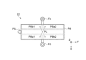
圧電アクチュエーター22は、図2Aおよび図2Bに示すように、矩形状の振動板(振動部)Pdの両面にそれぞれ面対称に設けられた5つの圧電素子(圧電素子PBa1,PBa2,PBb1,PBb2,PL)を備えている。5つの圧電素子PBa1,PBa2,PBb1,PBb2,PLは、それぞれ、圧電体と、圧電体を挟持する2つの電極と、で構成されている。5つの圧電素子PBa1,PBa2,PBb1,PBb2,PLのうち、振動板Pdの短手(幅)方向(X方向)の中央にある第1の圧電素子PLは、振動板Pdの長手方向(Y方向)のほぼ全体に亘る長方形の平面形状を有している。他の4つの圧電素子PBa1,PBa2,PBb1,PBb2は、第1の圧電素子PLを挟んで振動板Pdの四隅方向の位置に配置され、同一の長方形の平面形状を有している。4つの圧電素子PBa1,PBa2,PBb1,PBb2のうち、第1の対角にある一対の第2の圧電素子PBa1,PBa2は圧電体を挟む電極同士が電気的に接続されて一体の圧電素子として機能する。第2の対角にある一対の第3の圧電素子PBb1,PBb2も同様である。 As shown in FIG. 2A and FIG. 2B, the piezoelectric actuator 22 includes five piezoelectric elements (piezoelectric elements PBa1, PBa2, PBb1, PBb2, PBb2, PBb2, PBb2, PBb2, PBb2, PBb2, PBb2, PBb2, PBb2) provided on both sides of a rectangular vibration plate (vibration part) Pd. PL). Each of the five piezoelectric elements PBa1, PBa2, PBb1, PBb2, PL is composed of a piezoelectric body and two electrodes sandwiching the piezoelectric body. Of the five piezoelectric elements PBa1, PBa2, PBb1, PBb2, PL, the first piezoelectric element PL located at the center in the lateral (width) direction (X direction) of the diaphragm Pd is the longitudinal direction (Y) of the diaphragm Pd. Direction) and has a rectangular planar shape over almost the entire area. The other four piezoelectric elements PBa1, PBa2, PBb1, PBb2 are arranged at the four corners of the diaphragm Pd with the first piezoelectric element PL interposed therebetween, and have the same rectangular planar shape. Of the four piezoelectric elements PBa1, PBa2, PBb1 and PBb2, the pair of second piezoelectric elements PBa1 and PBa2 in the first diagonal are integrated piezoelectric elements in which electrodes sandwiching the piezoelectric body are electrically connected to each other. Function. The same applies to the pair of third piezoelectric elements PBb1 and PBb2 located on the second diagonal.

図3Aおよび図3Bを参照して、圧電アクチュエーター22の動作について説明する。図3Aおよび図3Bは、圧電アクチュエーター22の動作を示す説明図である。図3Aに示すように、第1の圧電素子PLは、駆動回路54から供給される高周波(超音波)の駆動信号に従って振動板Pdの長手方向(Y方向)に沿った縦振動を発生する。図3Bに示すように、第2の圧電素子PBa1,PBa2は、駆動回路54から供給される高周波(超音波)の駆動信号に従って振動板Pdの短手方向(X方向)に屈曲する屈曲振動を発生する。第3の圧電素子PBb1,PBb2も同様である。したがって、圧電アクチュエーター22は、第1の圧電素子PL、第2の圧電素子PBa1,PBa2、第3の圧電素子PBb1,PBb2によって、XY平面に沿った面内方向での超音波振動(超音波信号Su:図1参照)を発生させる。なお、以下の説明において、第1の圧電素子PL、第2の圧電素子PBa1,PBa2、第3の圧電素子PBb1,PBb2、および、振動板Pdを、「振動体」とも呼ぶ。 The operation of the piezoelectric actuator 22 will be described with reference to FIGS. 3A and 3B. 3A and 3B are explanatory views showing the operation of the piezoelectric actuator 22. As shown in FIG. 3A, the first piezoelectric element PL generates longitudinal vibration along the longitudinal direction (Y direction) of the diaphragm Pd in accordance with a high frequency (ultrasonic wave) drive signal supplied from the drive circuit 54. As shown in FIG. 3B, the second piezoelectric elements PBa1 and PBa2 generate bending vibration that bends in the lateral direction (X direction) of the diaphragm Pd in accordance with a high-frequency (ultrasonic wave) drive signal supplied from the drive circuit 54. appear. The same applies to the third piezoelectric elements PBb1 and PBb2. Therefore, the piezoelectric actuator 22 uses the first piezoelectric element PL, the second piezoelectric elements PBa1 and PBa2, and the third piezoelectric elements PBb1 and PBb2 to cause ultrasonic vibrations (ultrasonic signal) in the in-plane direction along the XY plane. Su: (see FIG. 1) is generated. In the following description, the first piezoelectric element PL, the second piezoelectric elements PBa1 and PBa2, the third piezoelectric elements PBb1 and PBb2, and the vibrating plate Pd are also referred to as “vibrators”.

圧電アクチュエーター22には、図2Aおよび図2Bに示すように、振動板Pdの両側の長辺の中央部に、それぞれ固定部Fcが設けられている。圧電アクチュエーター22は、固定部Fcをネジ等によって不図示の固定枠に固定することによって駆動部20内に固定される。 As shown in FIGS. 2A and 2B, the piezoelectric actuator 22 is provided with fixed portions Fc at the central portions of the long sides on both sides of the diaphragm Pd. The piezoelectric actuator 22 is fixed in the drive unit 20 by fixing the fixing unit Fc to a fixing frame (not shown) with screws or the like.

また、圧電アクチュエーター22には、振動板Pdの一方の短辺の中央部に突起部PSが設けられている。圧電アクチュエーター22は、図1に示すように、突起部PSを被駆動部30に接触させることが可能なように、突起部PSを被駆動部30に向けて配置されている。 Further, the piezoelectric actuator 22 is provided with a protrusion PS at the center of one short side of the diaphragm Pd. As shown in FIG. 1, the piezoelectric actuator 22 is arranged with the protrusion PS facing the driven portion 30 so that the protrusion PS can be brought into contact with the driven portion 30.

圧電アクチュエーター22は、上記した縦振動と屈曲振動との組み合わせにより、突起部PSを圧電アクチュエーター22のXY平面に沿った面内方向において楕円の軌道で運動させて被駆動部30を摺動する。この摺動により発生する駆動力によって、圧電アクチュエーター22は、被駆動部30を直線状の移動方向Dm(X方向)に、駆動部20に対して相対的に移動させる。なお、被駆動部30を駆動する際に圧電素子PBa1,PBa2,PBb1,PBb2,PLに供給される駆動信号の周波数は、振動体の共振周波数あるいはその近傍周波数(以下、単に「共振周波数」と呼ぶ)に設定される。本形態では、振動体の共振周波数は、1MHz(メガヘルツ)程度に設定されている。 The piezoelectric actuator 22 moves the protrusion PS in an in-plane direction along the XY plane of the piezoelectric actuator 22 in an elliptical orbit by the combination of the above-described longitudinal vibration and bending vibration, and slides on the driven portion 30. The driving force generated by this sliding causes the piezoelectric actuator 22 to move the driven portion 30 in the linear movement direction Dm (X direction) relative to the driving portion 20. The frequency of the drive signal supplied to the piezoelectric elements PBa1, PBa2, PBb1, PBb2, PL when driving the driven part 30 is the resonance frequency of the vibrating body or a frequency close thereto (hereinafter, simply referred to as “resonance frequency”). Set to). In this embodiment, the resonance frequency of the vibrating body is set to about 1 MHz (megahertz).

受信部としての超音波受信部40は、圧電アクチュエーター22の振動によって圧電アクチュエーター22から発信されて空中を伝播する超音波信号Suを受信する。超音波受信部40には、圧電アクチュエーター22から発信される共振周波数の超音波信号Suを受信可能な受波器が用いられる。超音波受信部40は、被駆動部30の基準位置、本例では、移動方向Dmの左側の端部、即ち被駆動部30の駆動部20と反対側の端部に位置し、駆動部20と反対側を向くように取り付けられている。障害物Hが存在する場合の超音波信号Suは、障害物Hから反射される反射波Rsuを受信することにより、障害物Hの無い場合の超音波信号Suと異なる状態となる。したがって、障害物Hが存在する場合、超音波受信部40は、障害物Hの無い場合と異なる状態の超音波信号Suを受信することになる。超音波受信部40は、受信した音波信号Suの状態に基づいた出力信号を、後述する超音波検出回路56に出力する。 The ultrasonic wave receiving unit 40 as a receiving unit receives the ultrasonic wave signal Su transmitted from the piezoelectric actuator 22 by the vibration of the piezoelectric actuator 22 and propagating in the air. As the ultrasonic wave receiving unit 40, a wave receiver that can receive the ultrasonic wave signal Su of the resonance frequency transmitted from the piezoelectric actuator 22 is used. The ultrasonic wave receiving unit 40 is located at the reference position of the driven unit 30, that is, the left end of the driven unit 30 in the moving direction Dm, that is, the end of the driven unit 30 opposite to the drive unit 20. It is attached so that it faces the other side. By receiving the reflected wave Rsu reflected from the obstacle H, the ultrasonic signal Su in the case where the obstacle H is present is in a different state from the ultrasonic signal Su in the absence of the obstacle H. Therefore, when the obstacle H exists, the ultrasonic wave receiving unit 40 receives the ultrasonic signal Su in a state different from that in the case where there is no obstacle H. The ultrasonic wave reception unit 40 outputs an output signal based on the state of the received sound wave signal Su to the ultrasonic wave detection circuit 56 described later.

制御部50は、駆動部20や超音波受信部40と接続されている。制御部50は、判断部51および電力制御部55を含む制御回路52と、記憶部53と、駆動回路54と、超音波検出回路56と、を備え、駆動部20の有する圧電アクチュエーター22の動作を制御する。 The control unit 50 is connected to the drive unit 20 and the ultrasonic wave reception unit 40. The control unit 50 includes a control circuit 52 including a determination unit 51 and a power control unit 55, a storage unit 53, a drive circuit 54, and an ultrasonic wave detection circuit 56, and the operation of the piezoelectric actuator 22 included in the drive unit 20. To control.

駆動回路54は、制御回路52の制御に従って通常の駆動動作のための駆動信号と、障害物Hの有無を検知するための超音波信号Suとを出力可能に構成されている。ここで、図4を参照して、駆動回路54の出力する圧電アクチュエーター22の駆動波形および超音波信号波形の一例について説明する。図4は、圧電アクチュエーター22の駆動波形および超音波信号波形の一例を示す説明図である。図4に示すように、通常の駆動動作において、駆動回路54は、圧電アクチュエーター22が上記した駆動動作によって被駆動部30を移動させる駆動信号Seを出力する。障害物Hの有無を検知するための超音波信号Suは、この駆動信号Seによって、空中を伝播する信号として圧電アクチュエーター22から発信される。 The drive circuit 54 is configured to be able to output a drive signal for a normal drive operation and an ultrasonic signal Su for detecting the presence or absence of the obstacle H under the control of the control circuit 52. Here, with reference to FIG. 4, an example of the drive waveform and the ultrasonic signal waveform of the piezoelectric actuator 22 output from the drive circuit 54 will be described. FIG. 4 is an explanatory diagram showing an example of the drive waveform of the piezoelectric actuator 22 and the ultrasonic signal waveform. As shown in FIG. 4, in a normal drive operation, the drive circuit 54 outputs a drive signal Se that causes the piezoelectric actuator 22 to move the driven part 30 by the drive operation described above. The ultrasonic signal Su for detecting the presence or absence of the obstacle H is transmitted from the piezoelectric actuator 22 as a signal propagating in the air by the drive signal Se.

なお、超音波信号Suは、駆動信号Seの周期と異なる周期で発信することができる。例えば、超音波信号Suは、図4に示すように、駆動信号Seにピーク波Spを重畳させ、このピーク波Spに基づいて発生した超音波振動によって発信される信号とすることができる。このようなピーク波Spによって超音波信号Suを出力することにより、圧電アクチュエーター22が複数設けられている構成においても、複数の圧電アクチュエーター22の超音波信号Suの出力タイミングを、それぞれ異ならせることが可能となり、圧電アクチュエーター22ごとの超音波信号Suを区別・判別することが可能となる。これにより、障害物Hの有無の検知とともに、被駆動部30に対する障害物の存在方向などを検知することが可能となる。 The ultrasonic signal Su can be transmitted in a cycle different from the cycle of the drive signal Se. For example, as shown in FIG. 4, the ultrasonic signal Su can be a signal generated by superimposing a peak wave Sp on the drive signal Se and generating ultrasonic vibration based on the peak wave Sp. By outputting the ultrasonic signal Su by such a peak wave Sp, the output timing of the ultrasonic signal Su of the plurality of piezoelectric actuators 22 can be made different even in the configuration in which the plurality of piezoelectric actuators 22 are provided. This makes it possible to distinguish and discriminate the ultrasonic signal Su for each piezoelectric actuator 22. As a result, it becomes possible to detect the presence or absence of the obstacle H as well as the presence direction of the obstacle with respect to the driven unit 30.

超音波検出回路56は、超音波受信部40で受信した超音波信号Suによって得られた出力信号に基づいて超音波検出信号を生成し、生成した超音波検出信号を記憶部53および制御回路52に出力する。 The ultrasonic detection circuit 56 generates an ultrasonic detection signal based on the output signal obtained by the ultrasonic signal Su received by the ultrasonic reception unit 40, and the generated ultrasonic detection signal is stored in the storage unit 53 and the control circuit 52. Output to.

記憶部53は、超音波検出回路56から出力された超音波検出信号を受信し、超音波信号Suの状態として記憶する。記憶部53は、例えば、試行などによって得られた障害物Hの無い場合の超音波信号Suを、基準超音波信号として記憶することができる。また、記憶部53は、駆動装置10において、繰り返し行われる通常の駆動動作状態における超音波信号Suを連続して記憶し、平均値化などの処理を行うことにより基準超音波信号を求めて記憶することができる。 The storage unit 53 receives the ultrasonic wave detection signal output from the ultrasonic wave detection circuit 56 and stores it as the state of the ultrasonic wave signal Su. The storage unit 53 can store, for example, the ultrasonic signal Su obtained when there is no obstacle H obtained by trial or the like as a reference ultrasonic signal. Further, the storage unit 53 continuously stores the ultrasonic signal Su in the normal driving operation state that is repeatedly performed in the driving device 10, and obtains and stores the reference ultrasonic signal by performing processing such as averaging. can do.

制御回路52は、超音波検出回路56から出力された超音波検出信号を受信し、障害物Hの有無を判断して圧電アクチュエーター22の駆動を制御する。制御回路52は、障害物Hの有無を判断する判断部51と、圧電アクチュエーター22へ供給する電力を制御する電力制御部55とを備えている。 The control circuit 52 receives the ultrasonic wave detection signal output from the ultrasonic wave detection circuit 56, determines the presence or absence of the obstacle H, and controls the drive of the piezoelectric actuator 22. The control circuit 52 includes a determination unit 51 that determines the presence or absence of the obstacle H, and a power control unit 55 that controls the power supplied to the piezoelectric actuator 22.

判断部51は、超音波検出回路56から出力された超音波検出信号、および記憶部53に記憶されている超音波信号Suの状態や基準超音波信号によって、被駆動部30の可動領域内に障害物Hが有るか否か(有無)を判断し、電力制御部55に判断信号を出力する。判断部51は、例えば繰り返し行われる通常の駆動動作状態における超音波信号Suの状態を時系列的に読み取り、予め設定された閾値を超える変化を生じた場合に、障害物Hが存在すると判断し、判断信号を出力することができる。 The determination unit 51 determines whether or not the ultrasonic detection signal output from the ultrasonic detection circuit 56, the state of the ultrasonic signal Su stored in the storage unit 53, or the reference ultrasonic signal within the movable region of the driven unit 30. It is determined whether or not there is an obstacle H (presence or absence), and a determination signal is output to the power control unit 55. For example, the determination unit 51 reads the state of the ultrasonic signal Su in the normal driving operation state that is repeatedly performed in time series, and determines that the obstacle H exists when a change exceeding a preset threshold value occurs. , It is possible to output a judgment signal.

また、判断部51は、例えば記憶部53に記憶されている基準超音波信号の状態と、被駆動部30の移動中(可動中)に超音波受信部40から出力される超音波信号Suの状態によって超音波検出回路56から出力された超音波検出信号とを比較する。そして、判断部51は、基準超音波信号の状態と超音波信号Suの状態とに変化を生じた場合に、障害物Hが存在すると判断し、判断信号を出力することができる。なお、基準超音波信号の状態と超音波信号Suの状態との変化は、例えば、その差が予め設定された閾値を超えた場合に変化を生じたと判断することができる。 The determination unit 51 also determines, for example, the state of the reference ultrasonic signal stored in the storage unit 53 and the ultrasonic signal Su output from the ultrasonic receiving unit 40 while the driven unit 30 is moving (moving). The ultrasonic detection signal output from the ultrasonic detection circuit 56 is compared depending on the state. Then, when the state of the reference ultrasonic signal and the state of the ultrasonic signal Su change, the determination unit 51 can determine that the obstacle H exists and output the determination signal. The change in the state of the reference ultrasonic signal and the state of the ultrasonic signal Su can be determined to have occurred, for example, when the difference exceeds a preset threshold value.

判断部51が、このような比較を行うことによって障害物Hの有無を判断することにより、簡便な方法で、容易に外乱などによる超音波信号Suのばらつきを排除することができ、障害物Hの有無の判断を高精度で行うことができる。 The determination unit 51 determines the presence or absence of the obstacle H by performing such comparison, and thus the variation of the ultrasonic signal Su due to disturbance or the like can be easily eliminated by a simple method, and the obstacle H can be eliminated. The presence or absence of can be determined with high accuracy.

電力制御部55は、圧電アクチュエーター22へ供給する電力を制御する。電力制御部55は、圧電アクチュエーター22へ所定の電力を供給し、供給された電力によって圧電アクチュエーター22が振動することによって、駆動部20と被駆動部30とが相対的に移動し、被駆動部30を移動方向Dmに移動させることができる。このように、電力制御部55は、駆動部20と被駆動部30との相対位置や例えば移動スピードなどの移動状態を制御することができる。電力制御部55は、判断部51から出力された判断信号により、圧電アクチュエーター22へ供給する電力を制御し、圧電アクチュエーター22の移動状態を制御する。ここで、圧電アクチュエーター22の移動状態とは、移動スピードを速めたり遅くしたりする、もしくは、移動を停止したり開始したりすることなどを含んでいる。 The power control unit 55 controls the power supplied to the piezoelectric actuator 22. The power control unit 55 supplies a predetermined electric power to the piezoelectric actuator 22, and the supplied electric power causes the piezoelectric actuator 22 to vibrate, whereby the driving unit 20 and the driven unit 30 move relatively, and the driven unit. The 30 can be moved in the movement direction Dm. In this way, the power control unit 55 can control the relative position between the driving unit 20 and the driven unit 30 and the moving state such as the moving speed. The power control unit 55 controls the power supplied to the piezoelectric actuator 22 according to the determination signal output from the determination unit 51, and controls the moving state of the piezoelectric actuator 22. Here, the moving state of the piezoelectric actuator 22 includes speeding up or slowing down the moving speed, stopping or starting the moving, and the like.

例えば、電力制御部55は、判断部51から出力された判断信号により、障害物Hが有りそうだと判断した場合には、圧電アクチュエーター22へ供給する電力を小さくし、圧電アクチュエーター22によって駆動される被駆動部30の移動スピードを遅くする。そして、さらに継続して判断部51が障害物Hの存在を判断している場合は、圧電アクチュエーター22への電力の供給を停止し、圧電アクチュエーター22を停止する。これにより、被駆動部30の移動を停止することができる。このように、障害物Hの存在を覚知した場合に、先ず被駆動部30の移動スピードを減速し、その後停止させることによって、被駆動部30を停止させる際の慣性衝撃を減少させることができ、急停止などによって駆動装置10の受けるダメージを少なくすることができる。 For example, when the power control unit 55 determines from the determination signal output from the determination unit 51 that the obstacle H is likely to exist, the power control unit 55 reduces the power supplied to the piezoelectric actuator 22 and is driven by the piezoelectric actuator 22. The moving speed of the driven part 30 is reduced. When the determination unit 51 continues to determine the presence of the obstacle H, the power supply to the piezoelectric actuator 22 is stopped and the piezoelectric actuator 22 is stopped. As a result, the movement of the driven part 30 can be stopped. In this way, when the presence of the obstacle H is detected, first, the moving speed of the driven part 30 is decelerated and then stopped, whereby the inertial impact when stopping the driven part 30 can be reduced. Therefore, it is possible to reduce damage to the drive device 10 due to a sudden stop or the like.

このように、判断部51から出力された判断信号によって電力制御部55が圧電アクチュエーター22へ供給する電力を制御することにより、駆動部20の駆動状態、即ち被駆動部30の移動スピード、移動停止など、被駆動部30の移動状態を容易に制御することができる。 In this way, the electric power control unit 55 controls the electric power supplied to the piezoelectric actuator 22 according to the judgment signal output from the judgment unit 51, so that the driving state of the driving unit 20, that is, the moving speed of the driven unit 30, the movement stop. As described above, the moving state of the driven portion 30 can be easily controlled.

次に、図5を参照して、駆動装置10における障害物Hの検出手順について説明する。図5は、第1実施形態に係る駆動装置10の障害物Hを検出する手順の概要を示すフローチャートである。なお、以下では、上述にて図1〜図4を参照して説明した駆動装置10の構成と同符号を用いて説明する。また、以下では、基準超音波信号の求め方の一例として、試行を行った場合の手順を示して説明する。 Next, the procedure for detecting the obstacle H in the drive device 10 will be described with reference to FIG. FIG. 5 is a flowchart showing an outline of the procedure for detecting the obstacle H of the drive device 10 according to the first embodiment. In addition, below, it demonstrates using the same code|symbol as the structure of the drive device 10 demonstrated with reference to FIGS. Further, in the following, as an example of how to obtain the reference ultrasonic signal, a procedure in the case of trial is shown and described.

先ず、制御回路52(電力制御部55)によって制御され、供給される電力によって駆動された圧電アクチュエーター22によって駆動部20を駆動し、被駆動部30の移動を行う(ステップS101)。このとき、圧電アクチュエーター22から発信された超音波信号Suは、超音波受信部40によって受信されている。 First, the drive unit 20 is driven by the piezoelectric actuator 22 controlled by the control circuit 52 (power control unit 55) and driven by the supplied power, and the driven unit 30 is moved (step S101). At this time, the ultrasonic wave signal Su transmitted from the piezoelectric actuator 22 is received by the ultrasonic wave receiver 40.

次に、制御回路52は、駆動部20の駆動による被駆動部30の移動が、基準超音波信号を求めるための試行であるか否かを判定する(ステップS103)。ここで制御回路52が「試行である」と判定した場合(ステップS103:Yes)に、記憶部53は、試行によって得られた障害物Hの無い場合の超音波信号Suを、基準超音波信号として記憶する(ステップS105)。なお、制御回路52が「試行でない」と判定した場合(ステップS103:No)は、基準超音波信号の状態と、現在受信している超音波信号Suに基づき超音波検出回路56から出力された超音波検出信号の状態とを比較する工程(ステップS107)に移行する。 Next, the control circuit 52 determines whether or not the movement of the driven portion 30 due to the driving of the driving portion 20 is a trial for obtaining the reference ultrasonic signal (step S103). Here, when the control circuit 52 determines that it is “trial” (step S103: Yes), the storage unit 53 uses the reference ultrasonic signal Su as the ultrasonic signal Su obtained when there is no obstacle H obtained by the trial. (Step S105). When the control circuit 52 determines that it is not a trial (step S103: No), it is output from the ultrasonic detection circuit 56 based on the state of the reference ultrasonic signal and the ultrasonic signal Su currently being received. The process proceeds to the step of comparing the state of the ultrasonic detection signal (step S107).

次に、制御回路52は、記憶部53に記憶された基準超音波信号を読み出し、その基準超音波信号の状態と、現在受信している超音波信号Suに基づき超音波検出回路56から出力された超音波検出信号の状態とを比較する(ステップS107)。 Next, the control circuit 52 reads the reference ultrasonic signal stored in the storage unit 53, and outputs it from the ultrasonic detecting circuit 56 based on the state of the reference ultrasonic signal and the ultrasonic signal Su currently received. The state of the ultrasonic detection signal is compared (step S107).

次に、制御回路52は、前述の比較によって、基準超音波信号の状態と、現在受信している超音波信号Suに基づき超音波検出回路56から出力された超音波検出信号の状態とに差が有るか否かを判定する(ステップS109)。なお、基準超音波信号の状態と、現在受信している超音波信号Suの状態との差の有無については、例えば、予め設定された閾値を超える変化を生じたか否かによって判定することができる。ここで、基準超音波信号の状態と、現在受信している超音波信号Suに基づき超音波検出回路56から出力された超音波検出信号とに差がある、即ち被駆動部30の可動領域内に「障害物Hが有る」と判断部51が判断した場合(ステップS109:Yes)は、障害物対処処理工程(ステップS111)に移行する。 Next, the control circuit 52 makes a difference between the state of the reference ultrasonic wave signal and the state of the ultrasonic wave detection signal output from the ultrasonic wave detection circuit 56 based on the ultrasonic wave signal Su currently received by the above comparison. It is determined whether or not is present (step S109). Whether or not there is a difference between the state of the reference ultrasonic signal and the state of the ultrasonic signal Su currently being received can be determined by, for example, whether or not a change exceeding a preset threshold value has occurred. .. Here, there is a difference between the state of the reference ultrasonic wave signal and the ultrasonic wave detection signal output from the ultrasonic wave detection circuit 56 based on the currently received ultrasonic wave signal Su, that is, within the movable area of the driven part 30. When the determination unit 51 determines that “there is an obstacle H” (step S109: Yes), the process proceeds to the obstacle handling process step (step S111).

なお、基準超音波信号の状態と、現在受信している超音波信号Suに基づき超音波検出回路56から出力された超音波検出信号とに差が無い、即ち被駆動部30の可動領域内には「障害物Hが無い」と判断部51が判断した場合(ステップS109:No)は、被駆動部30の移動を行う工程(ステップS101)に戻り、一連の手順を繰り返す。この場合、被駆動部30は、制御回路52(電力制御部55)によって制御、供給される電力によって駆動された圧電アクチュエーター22によって駆動部20が駆動されることによって駆動される。 It should be noted that there is no difference between the state of the reference ultrasonic signal and the ultrasonic detection signal output from the ultrasonic detection circuit 56 based on the currently received ultrasonic signal Su, that is, within the movable area of the driven part 30. When the determination unit 51 determines that "there is no obstacle H" (step S109: No), the process returns to the step of moving the driven unit 30 (step S101), and the series of procedures is repeated. In this case, the driven unit 30 is driven by driving the driving unit 20 by the piezoelectric actuator 22 driven by the electric power controlled and supplied by the control circuit 52 (power control unit 55).

障害物対処処理工程(ステップS111)では、判断部51から出力された判断信号により、電力制御部55の圧電アクチュエーター22へ供給する電力を制御し、圧電アクチュエーター22の移動状態を制御する。具体的な障害物対処処理の一例について、以下に説明する。電力制御部55は、判断部51から出力された判断信号により、「障害物Hが有りそうだ」と判断した場合には、先ず圧電アクチュエーター22へ供給する電力を低減させ、圧電アクチュエーター22によって駆動される被駆動部30の移動スピードを遅くする。そして、さらに継続して判断部51が、「障害物Hが有る」と判断している場合は、圧電アクチュエーター22への電力の供給を停止し、圧電アクチュエーター22の動作を停止させることにより、被駆動部30の移動を停止する。このように、障害物対処処理工程(ステップS111)では、障害物Hの存在を覚知した場合に、先ず被駆動部30の移動スピードを減速し、その後停止させることによって、被駆動部30を停止させる際の慣性衝撃を減少させるなどの障害物対処処理を行う。 In the obstacle handling process step (step S111), the power supplied to the piezoelectric actuator 22 of the power control unit 55 is controlled by the determination signal output from the determination unit 51, and the movement state of the piezoelectric actuator 22 is controlled. An example of a specific obstacle coping process will be described below. When the power control unit 55 determines from the determination signal output from the determination unit 51 that “the obstacle H is likely to exist”, the power control unit 55 first reduces the power supplied to the piezoelectric actuator 22 and is driven by the piezoelectric actuator 22. The moving speed of the driven part 30 is reduced. When the determination unit 51 further determines that “the obstacle H is present”, the supply of electric power to the piezoelectric actuator 22 is stopped and the operation of the piezoelectric actuator 22 is stopped. The movement of the drive unit 30 is stopped. As described above, in the obstacle handling process step (step S111), when the presence of the obstacle H is detected, first, the moving speed of the driven part 30 is decelerated, and then stopped, whereby the driven part 30 is stopped. Performs obstacle handling processing such as reducing inertial impact when stopping.

なお、上述では、基準超音波信号の求め方の一例として、試行の工程が設けられ、試行であるか否かを判定する工程(ステップS103)を有する場合の手順を示して説明したがこれに限らない。基準超音波信号は、駆動装置10において、繰り返し行われる通常の駆動動作状態における超音波信号Suを連続して記憶し、平均値化などの処理を行うことにより基準超音波信号を求めてもよい。この場合、試行であるか否かを判定する工程(ステップS103)では、判定がNoとなる。 In the above description, as an example of how to obtain the reference ultrasonic signal, a trial process is provided, and the procedure in the case of including the process (step S103) of determining whether or not the trial has been described has been described. Not exclusively. As the reference ultrasonic signal, the driving device 10 may continuously store the ultrasonic signal Su in the normal driving operation state that is repeatedly performed, and perform a process such as averaging to obtain the reference ultrasonic signal. .. In this case, in the step of determining whether or not it is a trial (step S103), the determination is No.

また、上述では、被駆動部30を移動させる駆動部20を単数設ける構成を例示して説明したが、駆動部20の配置個数は、複数であってもよい。駆動部20の配置個数を複数とすることにより、駆動力を大きくすることができ、より大きな被駆動部30を駆動することが可能となる。 Further, in the above description, the configuration in which the single drive unit 20 that moves the driven unit 30 is provided has been described as an example, but the number of the drive units 20 arranged may be plural. By providing a plurality of drive units 20, the driving force can be increased and a larger driven unit 30 can be driven.

以上説明したように、第1実施形態の駆動装置10では、被駆動部30を駆動する駆動力を出力する駆動源としての圧電アクチュエーター22を超音波信号Suの送波器として利用することにより、以下のような効果を奏することができる。 As described above, in the driving device 10 of the first embodiment, by using the piezoelectric actuator 22 as the drive source that outputs the driving force for driving the driven portion 30, as the wave transmitter of the ultrasonic signal Su, The following effects can be achieved.

(1)駆動装置10では、駆動部20に備えられた圧電アクチュエーター22の振動部から超音波信号Suが発信され、受信部としての超音波受信部40で受信された超音波信号Suに基づいて超音波受信部40から出力された出力信号により超音波検出回路56から出力された超音波検出信号により判断部51が障害物Hの有無を判断する。このように、被駆動部30を移動させる駆動部20のうちに超音波信号Suを発信する振動部としての振動板Pd(圧電アクチュエーター22)が備えられている。換言すれば、駆動部20と超音波信号Suを発信する振動板Pdとが一体的に構成されているため、駆動装置10の小型化・軽量化を実現することができる。 (1) In the driving device 10, the ultrasonic signal Su is transmitted from the vibrating section of the piezoelectric actuator 22 provided in the driving section 20, and based on the ultrasonic signal Su received by the ultrasonic receiving section 40 as a receiving section. The determination unit 51 determines the presence/absence of the obstacle H based on the ultrasonic detection signal output from the ultrasonic detection circuit 56 based on the output signal output from the ultrasonic reception unit 40. As described above, in the driving unit 20 that moves the driven unit 30, the diaphragm Pd (piezoelectric actuator 22) as a vibrating unit that transmits the ultrasonic signal Su is provided. In other words, since the drive unit 20 and the diaphragm Pd that transmits the ultrasonic signal Su are integrally configured, the drive device 10 can be made smaller and lighter.

(2)また、駆動装置10では、判断部51が、記憶部53に記憶されている障害物Hの無い場合の超音波信号Suである基準超音波信号の状態と、被駆動部30の移動中の超音波信号の状態とを比較し、その変化によって障害物Hが存在すると判断し、判断信号を出力する。このように、簡便な方法によって、容易に障害物Hの有無を判断することができる。 (2) Further, in the drive device 10, the determination unit 51 causes the determination unit 51 to store the state of the reference ultrasonic signal, which is the ultrasonic signal Su when there is no obstacle H, and the movement of the driven unit 30. The state of the ultrasonic signal in the inside is compared, it is judged that the obstacle H exists by the change, and a judgment signal is output. In this way, the presence or absence of the obstacle H can be easily determined by a simple method.

(3)また、駆動装置10では、判断部51から出力された判断信号によって電力制御部55が圧電アクチュエーター22へ供給する電力を制御することにより、駆動部20(被駆動部30)の駆動状態、換言すれば移動スピードの加減などを容易に制御することができる。 (3) In the drive device 10, the drive state of the drive unit 20 (driven unit 30) is controlled by controlling the electric power supplied to the piezoelectric actuator 22 by the power control unit 55 according to the determination signal output from the determination unit 51. In other words, it is possible to easily control the speed of movement.

(第2実施形態)
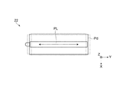
以下、本発明の第2実施形態に係る駆動装置を、図6Aおよび図6Bを参照して説明する。図6Aおよび図6Bは、第2実施形態に係る駆動装置の概略を示す説明図であり、図6Aは駆動装置の概略を示す平面図、図6Bは図6Aに示すP視からの側面図である。なお、図6Aおよび図6Bに示す第2実施形態に係る駆動装置100は、第1実施形態に係る駆動装置10と同じく、駆動部20と、被駆動部130と、受信部としての超音波受信部140,140aと、図1に示す制御部50(不図示)と、を備えている。なお、制御部50の構成・動作・障害物Hの検出手順は同様であるため、ここでの図示および説明を省略する。
(Second embodiment)
Hereinafter, a driving device according to the second embodiment of the present invention will be described with reference to FIGS. 6A and 6B. 6A and 6B are explanatory views showing the outline of the drive device according to the second embodiment, FIG. 6A is a plan view showing the outline of the drive device, and FIG. 6B is a side view from the P view shown in FIG. 6A. is there. The drive device 100 according to the second embodiment shown in FIGS. 6A and 6B is similar to the drive device 10 according to the first embodiment in that the drive unit 20, the driven unit 130, and the ultrasonic wave reception as the reception unit. The units 140 and 140a and the control unit 50 (not shown) shown in FIG. 1 are provided. Since the configuration/operation of the control unit 50 and the procedure for detecting the obstacle H are the same, illustration and description thereof are omitted here.

第2実施形態に係る駆動装置100は、第1実施形態の駆動装置10(図1参照)と比し、図6Aおよび図6Bに示すように、圧電アクチュエーター22を含む駆動部20によって駆動される被駆動部130が、回転軸134を中心軸として回転移動する点が異なっている。第2実施形態に係る駆動装置100は、ベース部133に固定された円筒状の本体部132と、本体部132と相対的に回転移動する被駆動部130とを備えている。そして、本体部132には、駆動部20および超音波受信部140aが備えられている。 The drive device 100 according to the second embodiment is driven by a drive unit 20 including a piezoelectric actuator 22, as shown in FIGS. 6A and 6B, as compared with the drive device 10 (see FIG. 1) of the first embodiment. The difference is that the driven part 130 rotates about a rotating shaft 134 as a central axis. The drive device 100 according to the second embodiment includes a cylindrical main body portion 132 fixed to the base portion 133, and a driven portion 130 that rotates and moves relative to the main body portion 132. The main body 132 is provided with the drive unit 20 and the ultrasonic receiving unit 140a.

駆動部20は、駆動力を発生する複数の圧電アクチュエーター22を有している。駆動部20は、複数の圧電アクチュエーター22の駆動力によって、被駆動部130を回転移動させる。このように、本実施形態の駆動部20は、圧電アクチュエーター22を用いた回転駆動装置としての機能を有している。 The drive unit 20 has a plurality of piezoelectric actuators 22 that generate a driving force. The driving unit 20 rotationally moves the driven unit 130 by the driving force of the plurality of piezoelectric actuators 22. As described above, the drive unit 20 of this embodiment has a function as a rotation drive device using the piezoelectric actuator 22.

本実施形態での圧電アクチュエーター22は、複数配置されている。複数の圧電アクチュエーター22は、円筒状の本体部132の外周に沿って配置され、突起部Psが被駆動部130に向くように、本体部132の外周に複数(本形態では、八つ(8個))が、ほぼ等間隔で取り付けられている。そして複数の圧電アクチュエーター22の駆動力により、被駆動部130を回転移動させる。このように、複数の圧電アクチュエーター22が、円周状に配置され、それぞれの圧電アクチュエーター22から超音波信号Suが発信される。これにより、障害物Hの存在する位置(方向)を精度よく検知することができる。また、複数の圧電アクチュエーター22を用いているため、より大きな駆動力(本形態では回転力)を得ることができる。なお、圧電アクチュエーター22の配置は、必ずしも等間隔である必要はなく、任意の位置に配置することができる。 A plurality of piezoelectric actuators 22 in this embodiment are arranged. The plurality of piezoelectric actuators 22 are arranged along the outer periphery of the cylindrical main body portion 132, and the plurality of piezoelectric actuators 22 are arranged on the outer periphery of the main body portion 132 (in this embodiment, eight (8 )) are attached at approximately equal intervals. Then, the driven portion 130 is rotationally moved by the driving force of the plurality of piezoelectric actuators 22. In this way, the plurality of piezoelectric actuators 22 are arranged in a circumferential shape, and the ultrasonic signal Su is transmitted from each piezoelectric actuator 22. As a result, the position (direction) of the obstacle H can be detected with high accuracy. Further, since a plurality of piezoelectric actuators 22 are used, a larger driving force (rotational force in this embodiment) can be obtained. The piezoelectric actuators 22 do not necessarily have to be arranged at equal intervals, and can be arranged at any position.

第2実施形態の圧電アクチュエーター22について説明する。第2実施形態の圧電アクチュエーター22は、図2Aおよび図2Bを参照して説明した第1実施形態と同様であり、矩形状の振動板(振動部)Pdの両面にそれぞれ面対称に設けられた5つの圧電素子(圧電素子PBa1,PBa2,PBb1,PBb2,PL)を備えている。なお、第2実施形態の圧電アクチュエーター22の構成は、第1実施形態と同様であるため、ここでの説明は省略する。 The piezoelectric actuator 22 of the second embodiment will be described. The piezoelectric actuator 22 of the second embodiment is the same as that of the first embodiment described with reference to FIGS. 2A and 2B, and is provided symmetrically on both surfaces of a rectangular diaphragm (vibrating portion) Pd. It has five piezoelectric elements (piezoelectric elements PBa1, PBa2, PBb1, PBb2, PL). Note that the configuration of the piezoelectric actuator 22 of the second embodiment is the same as that of the first embodiment, so description thereof will be omitted here.

図3Aおよび図3Bを参照して第1実施形態で説明したように、第1の圧電素子PLは、駆動回路54(図1参照)から供給される高周波(超音波)の駆動信号に従って振動板Pdの長手方向(Y方向)に沿った縦振動を発生する。第2の圧電素子PBa1,PBa2は、駆動回路54(図1参照)から供給される高周波(超音波)の駆動信号に従って振動板Pdの短手方向(X方向)に屈曲する屈曲振動を発生する。第3の圧電素子PBb1,PBb2も同様である。したがって、圧電アクチュエーター22は、第1の圧電素子PL、第2の圧電素子PBa1,PBa2、第3の圧電素子PBb1,PBb2によって、XY平面に沿った面内方向での超音波振動(超音波信号Su:図6A参照)を発生させることができる。 As described in the first embodiment with reference to FIGS. 3A and 3B, the first piezoelectric element PL is the diaphragm according to the high-frequency (ultrasonic wave) drive signal supplied from the drive circuit 54 (see FIG. 1). Vertical vibration is generated along the longitudinal direction (Y direction) of Pd. The second piezoelectric elements PBa1 and PBa2 generate bending vibration that bends in the lateral direction (X direction) of the diaphragm Pd in accordance with a high frequency (ultrasonic wave) drive signal supplied from the drive circuit 54 (see FIG. 1). .. The same applies to the third piezoelectric elements PBb1 and PBb2. Therefore, the piezoelectric actuator 22 uses the first piezoelectric element PL, the second piezoelectric elements PBa1 and PBa2, and the third piezoelectric elements PBb1 and PBb2 to cause ultrasonic vibration (ultrasonic signal) in the in-plane direction along the XY plane. Su: see FIG. 6A).

第2実施形態の圧電アクチュエーター22は、被駆動部130を回転移動させることができる。図6Aおよび図6Bに示すように、圧電アクチュエーター22の突起部PSは、被駆動部130の一方板面の外周部に接触している。そして、圧電アクチュエーター22は、図3Aおよび図3Bを参照して第1実施形態で説明したように、第1の圧電素子PLにおける縦振動と、第2の圧電素子PBa1,PBa2、および第3の圧電素子PBb1,PBb2における屈曲振動との組み合わせにより、突起部PSを圧電アクチュエーター22のXY平面に沿った面内方向において楕円の軌道で運動させて被駆動部130を摺動する。この摺動により発生する駆動力によって、圧電アクチュエーター22は、被駆動部130を、被駆動部130の中心部に位置する回転軸134回りに所定の方向に回転移動させることができる。以上のように、圧電アクチュエーター22を、回転駆動源として用いることが可能である。 The piezoelectric actuator 22 of the second embodiment can rotate the driven part 130. As shown in FIGS. 6A and 6B, the protrusion PS of the piezoelectric actuator 22 is in contact with the outer peripheral portion of the one plate surface of the driven portion 130. Then, as described in the first embodiment with reference to FIGS. 3A and 3B, the piezoelectric actuator 22 causes the longitudinal vibration in the first piezoelectric element PL, the second piezoelectric elements PBa1, PBa2, and the third piezoelectric element PBa1. By combining with the bending vibrations in the piezoelectric elements PBb1 and PBb2, the protrusion PS is moved in an in-plane direction along the XY plane of the piezoelectric actuator 22 in an elliptical orbit to slide on the driven portion 130. Due to the driving force generated by this sliding, the piezoelectric actuator 22 can rotate the driven portion 130 in a predetermined direction around the rotation shaft 134 located at the center of the driven portion 130. As described above, the piezoelectric actuator 22 can be used as a rotary drive source.

被駆動部130は、被駆動部130に固定された回転アーム131を含み、円筒状の本体部132の中心部に設けられた回転軸134に取り付けられて、円周状に回転移動する移動方向Rmに沿って移動可能に設けられている。被駆動部130に固定された回転アーム131は、駆動部20の回転移動に連れて移動し、移動方向Rmに沿った円周状の回転移動を行うことができる。 The driven part 130 includes a rotating arm 131 fixed to the driven part 130, is attached to a rotating shaft 134 provided at the center of a cylindrical main body part 132, and is rotated in a circumferential direction. It is provided so as to be movable along Rm. The rotary arm 131 fixed to the driven part 130 moves along with the rotational movement of the drive part 20, and can perform a circumferential rotational movement along the movement direction Rm.

受信部としての超音波受信部140は、被駆動部130の基準位置、本例では、回転移動の先端に近似する回転アーム131の先端部に、回転方向の両側に一つずつ取り付けられている。二つの超音波受信部140は、回転移動する移動方向Rmの両方向に一つずつ向くように配置されている。このように超音波受信部140を配置することにより、両側の移動方向の障害物Hを捕捉することが可能となる。さらに、受信部としての超音波受信部140aは、円筒状の本体部132の外周に沿って配置され、外側を向くように本体部132の外周に複数(本形態では、四つ(4個))が、ほぼ等間隔で取り付けられている。このように、複数の超音波受信部140aが、円周状に配置されていることから、全方向からの超音波信号Su(反射波Rsu)を、効率よく受信することができる。なお、本実施形態の構成では、超音波受信部140,140aを、回転アーム131の先端部と、本体部132の外周との両方に設ける構成例で説明したが、回転アーム131の先端部、および本体部132の外周のいずれかに設ける構成でもよい。 The ultrasonic wave receiving portion 140 as a receiving portion is attached to the reference position of the driven portion 130, in this example, to the tip end portion of the rotary arm 131 which approximates the tip end of the rotational movement, one on each side in the rotational direction. .. The two ultrasonic wave receiving units 140 are arranged so as to face one by one in both directions of the rotational movement Rm. By arranging the ultrasonic receiver 140 in this way, it is possible to capture the obstacles H in the moving direction on both sides. Further, the ultrasonic receiving units 140a as receiving units are arranged along the outer circumference of the cylindrical main body 132, and a plurality (four (four) in this embodiment) are provided on the outer circumference of the main body 132 so as to face outward. ) Are attached at approximately equal intervals. As described above, since the plurality of ultrasonic wave receiving units 140a are arranged in a circumferential shape, the ultrasonic wave signal Su (reflected wave Rsu) from all directions can be efficiently received. In the configuration of the present embodiment, the ultrasonic receivers 140 and 140a have been described as the configuration example in which they are provided on both the tip of the rotary arm 131 and the outer periphery of the main body 132. Alternatively, the structure may be provided on either the outer circumference of the main body 132.

以上説明したように、第2実施形態の駆動装置100では、被駆動部130を回転させる駆動力を出力する駆動源としての圧電アクチュエーター22を超音波信号Suの送波器として利用している。加えて上述の構成を用いることにより、第1実施形態の効果に加え、第2実施形態の駆動装置100では、次のような効果を奏することができる。 As described above, in the drive device 100 of the second embodiment, the piezoelectric actuator 22 as a drive source that outputs the drive force that rotates the driven portion 130 is used as a transmitter of the ultrasonic signal Su. In addition, by using the above-described configuration, in addition to the effects of the first embodiment, the drive device 100 of the second embodiment can achieve the following effects.

(1)第2実施形態の駆動装置100によれば、複数の圧電アクチュエーター22が、円筒状の本体部132の外周に沿って配置され、複数の圧電アクチュエーター22の駆動力により、被駆動部130を回転移動させる。このように、複数の圧電アクチュエーター22が、円周状に配置され、それぞれの圧電アクチュエーター22から超音波信号Suが発信される。これにより、障害物Hの存在する位置(方向)を精度よく検知することができる。また、複数の圧電アクチュエーター22を用いているため、より大きな駆動力(本形態では回転力)を得ることができる。 (1) According to the driving device 100 of the second embodiment, the plurality of piezoelectric actuators 22 are arranged along the outer periphery of the cylindrical main body portion 132, and the driven portion 130 is driven by the driving force of the plurality of piezoelectric actuators 22. To rotate. In this way, the plurality of piezoelectric actuators 22 are arranged in a circumferential shape, and the ultrasonic signal Su is transmitted from each piezoelectric actuator 22. As a result, the position (direction) of the obstacle H can be detected with high accuracy. Further, since a plurality of piezoelectric actuators 22 are used, a larger driving force (rotational force in this embodiment) can be obtained.

(2)また、複数の超音波受信部140aが、円周状に配置されていることから、全方向からの超音波信号Su(反射波Rsu)を、効率よく受信することができる。また、超音波信号Suの異常状態を検知した超音波受信部140aを特定することにより、障害物Hの存在位置を覚知することができる。 (2) Further, since the plurality of ultrasonic wave receiving units 140a are arranged in a circumferential shape, the ultrasonic wave signal Su (reflected wave Rsu) from all directions can be efficiently received. In addition, by specifying the ultrasonic wave receiving unit 140a that has detected the abnormal state of the ultrasonic wave signal Su, it is possible to detect the existing position of the obstacle H.

(第3実施形態)
以下、図7を参照して圧電アクチュエーター22を用いた圧電モーター200について説明する。なお、図7は、第3実施形態に係る圧電モーター200の動作を示す説明図である。また、図7では、圧電アクチュエーター22をネジ等によって不図示の固定枠に固定する固定部Fcについては、図示の都合上、省略している。
(Third Embodiment)
Hereinafter, the piezoelectric motor 200 using the piezoelectric actuator 22 will be described with reference to FIG. 7. 7. FIG. 7 is an explanatory diagram showing the operation of the piezoelectric motor 200 according to the third embodiment. Further, in FIG. 7, a fixing portion Fc for fixing the piezoelectric actuator 22 to a fixing frame (not shown) with screws or the like is omitted for convenience of illustration.

第3実施形態に係る圧電モーター200は、前述した圧電アクチュエーター22を備えている。圧電アクチュエーター22は、被駆動部としてのローター230を回転移動させる機能を有している。図7に示すように、圧電アクチュエーター22の突起部PSは、被駆動部としてのローター230の外周に接触している。図7に示す例では、2つの第1の圧電素子PBb1,PBb2の矢印Sの方向への伸縮に応じて、振動板Pdが振動板Pdの平面内で屈曲振動し、これに応じて、突起部PSの先端が矢印Qの向きに往復運動するか、または、楕円運動する。その結果、ローター230は、その中心に位置する回転軸234の周りに所定の方向R(図7では時計回り方向)に回転する。なお、2つの第2の圧電素子PBa1,PBa2(図1参照)に交流電圧または脈流電圧を印加する場合には、ローター230は逆方向に回転する。なお、図4Aを用いて説明したように、中央に位置する第1の圧電素子PLの伸縮に応じて、圧電アクチュエーター22が長手方向に伸縮するので、突起部PSからローター230に与える力をより大きくすることが可能である。 The piezoelectric motor 200 according to the third embodiment includes the piezoelectric actuator 22 described above. The piezoelectric actuator 22 has a function of rotating the rotor 230 as a driven portion. As shown in FIG. 7, the protrusion PS of the piezoelectric actuator 22 is in contact with the outer periphery of the rotor 230 as the driven portion. In the example shown in FIG. 7, the diaphragm Pd flexurally vibrates in the plane of the diaphragm Pd in response to the expansion and contraction of the two first piezoelectric elements PBb1 and PBb2 in the direction of the arrow S, and accordingly the protrusion The tip of the part PS reciprocates in the direction of arrow Q or makes an elliptical motion. As a result, the rotor 230 rotates in a predetermined direction R (clockwise direction in FIG. 7) around the rotation shaft 234 located at the center thereof. When applying an alternating voltage or a pulsating voltage to the two second piezoelectric elements PBa1 and PBa2 (see FIG. 1), the rotor 230 rotates in the opposite direction. As described with reference to FIG. 4A, the piezoelectric actuator 22 expands and contracts in the longitudinal direction according to the expansion and contraction of the first piezoelectric element PL located in the center, so that the force applied from the protrusion PS to the rotor 230 is further increased. It can be increased.

第3実施形態に係る圧電モーター200によれば、以上のように、圧電アクチュエーター22を回転駆動源として用いることができ、より小型の圧電モーター200を提供することができる。 According to the piezoelectric motor 200 according to the third embodiment, as described above, the piezoelectric actuator 22 can be used as a rotary drive source, and a smaller piezoelectric motor 200 can be provided.

なお、第1実施形態の駆動装置10では、固定された駆動部20に対して被駆動部30が移動方向Dmに沿って移動する構成を例に説明したが、被駆動部30が固定され、駆動部20が被駆動部30に対して移動方向Dmに沿って移動する構成としてもよい。また、第2実施形態の駆動装置100では、本体部132に固定された駆動部20に対して被駆動部130が移動方向Rmに沿って移動する構成を例に説明したが、被駆動部130が固定され、駆動部20が被駆動部130に対して移動方向Rmに沿って移動する構成としてもよい。 In the drive device 10 of the first embodiment, the configuration in which the driven portion 30 moves along the movement direction Dm with respect to the fixed driving portion 20 has been described as an example, but the driven portion 30 is fixed, The drive unit 20 may be configured to move with respect to the driven unit 30 along the movement direction Dm. Further, in the drive device 100 of the second embodiment, the configuration in which the driven portion 130 moves along the movement direction Rm with respect to the driving portion 20 fixed to the main body portion 132 has been described as an example, but the driven portion 130 is described. May be fixed, and the drive unit 20 may move in the movement direction Rm with respect to the driven unit 130.

また、上述した圧電アクチュエーター22(図2A、および図2B参照)の構造に限定されるものではなく、圧電素子を用いた種々の圧電アクチュエーターを利用することができる。 Further, the structure of the piezoelectric actuator 22 (see FIGS. 2A and 2B) described above is not limited, and various piezoelectric actuators using a piezoelectric element can be used.

(第4実施形態)
上述した圧電アクチュエーター22(駆動部20)は、共振を利用することで被駆動部30,130に対して大きな力を与えることができるものであり、各種の装置に適用可能である。圧電アクチュエーター22(駆動部20)は、例えば、ロボット(電子部品搬送装置(ICハンドラー)も含む)、ハンド(指アシスト装置を含む)、投薬用ポンプ、時計のカレンダー送り装置、印刷装置(例えば紙送り機構)等の各種の機器における駆動装置として用いることができる。以下、代表的な実施の形態としてのロボットについて説明する。
(Fourth Embodiment)
The piezoelectric actuator 22 (driving unit 20) described above can apply a large force to the driven units 30 and 130 by utilizing resonance, and is applicable to various devices. The piezoelectric actuator 22 (driving unit 20) is, for example, a robot (including an electronic component carrying device (IC handler)), a hand (including a finger assist device), a medication pump, a calendar calendar feeding device, and a printing device (for example, paper). It can be used as a driving device in various devices such as a feeding mechanism). Hereinafter, a robot as a representative embodiment will be described.

以下、上述した圧電アクチュエーター22を圧電モーターとして利用したロボットについて、図8および図9を参照して説明する。図8は、圧電アクチュエーター22(駆動部20)を用いたロボットの一実施形態としてロボットアームを有するロボットを示す説明図である。図9は、エンドエフェクターが取り付けられたロボットアームの手首部分を拡大して示す説明図である。 Hereinafter, a robot using the above-mentioned piezoelectric actuator 22 as a piezoelectric motor will be described with reference to FIGS. 8 and 9. FIG. 8 is an explanatory diagram showing a robot having a robot arm as an embodiment of a robot using the piezoelectric actuator 22 (driving unit 20). FIG. 9 is an explanatory view showing an enlarged wrist portion of the robot arm to which the end effector is attached.

図8に示すように、ロボット2000は、第1アーム2100および第2アーム2200を少なくとも有するアーム部と、第1アーム2100の先端に取り付けられるエンドエフェクターとしてのロボットハンド3000と、を備えている。 As shown in FIG. 8, the robot 2000 includes an arm unit having at least a first arm 2100 and a second arm 2200, and a robot hand 3000 as an end effector attached to the tip of the first arm 2100.

アーム部(「腕部」とも呼ぶ)は、複数本のリンク部2012(「リンク部材」とも呼ぶ)と、それらリンク部2012の間を回動または屈曲可能な状態で接続する複数の関節部2020と、支持部としての基台2010と、を有している。なお、第1アーム2100は、支持部としての基台2010に、基台2010に接続された関節部2020を介して接続され、基台2010に対して相対移動可能である。 The arm portion (also referred to as “arm portion”) includes a plurality of link portions 2012 (also referred to as “link members”) and a plurality of joint portions 2020 that connect the link portions 2012 in a rotatable or bendable state. And a base 2010 as a support part. The first arm 2100 is connected to a base 2010 serving as a support via a joint 2020 connected to the base 2010 and is movable relative to the base 2010.

また、第2アーム2200は、基台2010と第1アーム2100との間に位置し、基台2010および第1アーム2100のそれぞれと、関節部2020を介して接続されている。なお、第2アーム2200は、基台2010および第1アーム2100のそれぞれと相対移動可能である。 The second arm 2200 is located between the base 2010 and the first arm 2100, and is connected to each of the base 2010 and the first arm 2100 via the joint 2020. The second arm 2200 can move relative to each of the base 2010 and the first arm 2100.

それぞれの関節部2020には、各回動軸X1〜X6について、それぞれ上述した圧電アクチュエーター22(駆動部20)が内蔵されており、圧電アクチュエーター22を用いて関節部2020を各回動軸X1〜X6の周りに任意の角度さけ回動または屈曲させることが可能である。なお、図8には、回動軸X5に対して上述した圧電アクチュエーター22(駆動部20)が設けられている例が示されている。 The above-mentioned piezoelectric actuator 22 (driving unit 20) is incorporated in each joint section 2020 for each of the rotation axes X1 to X6, and the joint section 2020 is connected to each of the rotation axes X1 to X6 by using the piezoelectric actuator 22. It is possible to rotate or bend around any angle. Note that FIG. 8 shows an example in which the above-described piezoelectric actuator 22 (driving unit 20) is provided with respect to the rotation axis X5.

第1アーム2100の先端には、ロボットハンド3000が接続されている。ロボットハンド3000は、一対の把持部3003を備えている。ロボットハンド3000にも上述した圧電アクチュエーター22(駆動部20)が内蔵されており、圧電アクチュエーター22を用いて把持部3003を開閉して物を把持することが可能である。なお、第1アーム2100の先端には、図示されない受信部としての超音波受信部(図1に示す超音波受信部40)が配設されている。換言すれば、図示されない受信部としての超音波受信部は、第1アーム2100を回転駆動させる圧電アクチュエーター22(駆動部20)よりも先端側に設けられている。 A robot hand 3000 is connected to the tip of the first arm 2100. The robot hand 3000 includes a pair of grips 3003. The above-described piezoelectric actuator 22 (driving unit 20) is also incorporated in the robot hand 3000, and the piezoelectric actuator 22 can be used to open and close the gripping unit 3003 to grip an object. An ultrasonic wave receiving unit (ultrasonic wave receiving unit 40 shown in FIG. 1) as a receiving unit (not shown) is provided at the tip of the first arm 2100. In other words, the ultrasonic wave receiving unit (not shown) as a receiving unit is provided on the tip side of the piezoelectric actuator 22 (driving unit 20) that rotationally drives the first arm 2100.

このように、圧電アクチュエーター22よりも先端側に位置する第1アーム2100に受信部としての超音波受信部が設けられていることから、第1アーム2100の可動範囲内の障害物H(図1参照)に近い位置で超音波信号Su(図1参照)を受信することができる。これにより、障害物Hの有無による超音波信号Suの変化を、より精度よく検知することができる。 As described above, since the first arm 2100 located on the tip side of the piezoelectric actuator 22 is provided with the ultrasonic wave receiving portion as a receiving portion, the obstacle H within the movable range of the first arm 2100 (see FIG. 1). The ultrasonic signal Su (see FIG. 1) can be received at a position close to (see FIG. 1). As a result, the change in the ultrasonic signal Su due to the presence or absence of the obstacle H can be detected more accurately.

また、ロボット2000は、図示しないアーム制御部を備えている。アーム制御部は、圧電アクチュエーター22から発信された超音波信号Suの状態を、第1アームの先端部に設けられた受信部としての超音波受信部(不図示)が受信することによって、第1アーム2100の可動範囲内に障害物H(図1参照)が有るか否かを検知し、第1アーム2100と障害物Hとの衝突を回避するための制御を行う。具体的にアーム制御部は、図1に示す駆動装置10の判断部51が第1アーム2100の可動範囲内に障害物Hが有ると判断したときには、第1アーム2100と障害物Hとの衝突を回避するため、第1アーム2100の移動スピードを遅くしたり、第1アーム2100の移動を停止したりする。 In addition, the robot 2000 includes an arm control unit (not shown). The arm control unit receives the state of the ultrasonic signal Su transmitted from the piezoelectric actuator 22 by an ultrasonic wave receiving unit (not shown) as a receiving unit provided at the tip of the first arm, and thereby the first It detects whether or not there is an obstacle H (see FIG. 1) within the movable range of the arm 2100, and performs control for avoiding a collision between the first arm 2100 and the obstacle H. Specifically, when the determination unit 51 of the drive device 10 illustrated in FIG. 1 determines that the obstacle H is within the movable range of the first arm 2100, the arm control unit collides with the first arm 2100 and the obstacle H. In order to avoid this, the moving speed of the first arm 2100 is slowed or the movement of the first arm 2100 is stopped.

上述のようなアーム制御部の制御により、第1アームの2100の可動範囲内に障害物Hが有る場合に、第1アーム2100と障害物Hとの衝突を回避することができる。また、衝突の回避動作において、第1アーム2100の動作を、例えば移動スピードを急減速させたり急停止させたりするなど急激に変化させることを抑制することが可能となり、ロボット2000への負荷を減少させることが可能となる。 By the control of the arm control unit as described above, it is possible to avoid the collision between the first arm 2100 and the obstacle H when the obstacle H is in the movable range of the first arm 2100. Further, in the collision avoidance operation, it is possible to prevent the operation of the first arm 2100 from abruptly changing, for example, by suddenly decelerating the moving speed or suddenly stopping the moving speed, thereby reducing the load on the robot 2000. It becomes possible.

図9は、図8に示したロボット2000のロボットハンド3000を含む手首部分の説明図である。手首の関節部2020は、手首回動部2022を挟持しており、手首回動部2022に手首のリンク部2012が、手首回動部2022の回動軸X6周りに回動可能に取り付けられている。手首回動部2022は、上述した駆動装置100(図6A、図6B参照)の複数の圧電アクチュエーター22が内蔵されており、手首のリンク部2012には、図6A、図6Bに示されている駆動装置100および被駆動部130に相当する駆動装置100と、駆動装置100の被駆動部130とを備えている。駆動装置100は、手首のリンク部2012およびロボットハンド3000を回動軸X6周りに回動させる。ロボットハンド3000には、複数本の把持部3003が立設されている。把持部3003の基端部はロボットハンド3000内で移動可能となっており、この把持部3003の根元の部分に駆動装置10(図1参照)の駆動部20の圧電アクチュエーター22が搭載されている。把持部3003の基端部が駆動装置10の被駆動部30に相当する。駆動装置10を動作させることで、把持部3003を移動させて対象物を把持することができる。 FIG. 9 is an explanatory diagram of a wrist portion including the robot hand 3000 of the robot 2000 shown in FIG. The wrist joint part 2020 holds the wrist rotation part 2022, and the wrist link part 2012 is attached to the wrist rotation part 2022 so as to be rotatable around the rotation axis X6 of the wrist rotation part 2022. There is. The wrist rotation unit 2022 incorporates the plurality of piezoelectric actuators 22 of the drive device 100 (see FIGS. 6A and 6B) described above, and the wrist link unit 2012 is illustrated in FIGS. 6A and 6B. The driving device 100 and the driven part 130 correspond to the driving device 100 and the driven part 130 of the driving device 100. The drive device 100 rotates the link portion 2012 of the wrist and the robot hand 3000 around the rotation axis X6. The robot hand 3000 has a plurality of gripping parts 3003 provided upright. The base end of the grip 3003 is movable in the robot hand 3000, and the piezoelectric actuator 22 of the drive unit 20 of the drive unit 10 (see FIG. 1) is mounted at the base of the grip 3003. .. The base end portion of the grip portion 3003 corresponds to the driven portion 30 of the drive device 10. By operating the driving device 10, the gripper 3003 can be moved to grip an object.

なお、ロボットとしては、単腕のロボットに限らず、腕の数が2以上の多腕ロボットにも圧電アクチュエーター22を備えた駆動装置10,100を適用することが可能である。ここで、手首の関節部2020やロボットハンド3000の内部には、圧電アクチュエーター22の他に、力覚センサーやジャイロセンサー等の各種装置に電力を供給する電力線や、信号を伝達する信号線等が含まれ、非常に多くの配線が必要になる。従って、関節部2020やロボットハンド3000の内部に配線を配置することは非常に困難だった。しかしながら、上述した実施形態の圧電アクチュエーター22(駆動部20)は、通常の電動モーターや、従来の圧電駆動装置よりも駆動電流を小さくできるので、関節部2020(特に、第1アーム2100の先端の関節部)やロボットハンド3000のような小さな空間でも配線を配置することが可能になる。 Note that the robot is not limited to a single-arm robot, and the drive devices 10 and 100 having the piezoelectric actuator 22 can be applied to a multi-arm robot having two or more arms. Here, inside the joint part 2020 of the wrist and the robot hand 3000, in addition to the piezoelectric actuator 22, there are power lines for supplying power to various devices such as force sensors and gyro sensors, and signal lines for transmitting signals. Included and requires a great deal of wiring. Therefore, it is very difficult to arrange the wiring inside the joint 2020 and the robot hand 3000. However, since the piezoelectric actuator 22 (driving unit 20) of the above-described embodiment can make the driving current smaller than that of the normal electric motor or the conventional piezoelectric driving device, the joint unit 2020 (particularly, the tip of the first arm 2100). It is possible to arrange the wiring even in a small space such as a joint part) or the robot hand 3000.

上記説明では、ロボットハンド3000を備えるロボット2000を例にとって説明したが、ロボットハンド3000は、ロボット2000の部品としてのみならず、単独の製品として構成されていても良い。 In the above description, the robot 2000 including the robot hand 3000 has been described as an example, but the robot hand 3000 may be configured not only as a component of the robot 2000 but also as a single product.

以上説明したように、本実施形態のロボット2000は、関節部2020に、上記実施形態の圧電アクチュエーター22(図1参照)を備える駆動装置10,100,200が用いられていることにより、関節部2020を介して移動する第1アーム2100を備えたロボット2000の小型化や軽量化を図ることができる。 As described above, the robot 2000 of the present embodiment uses the drive unit 10, 100, 200 including the piezoelectric actuator 22 (see FIG. 1) of the above-described embodiment for the joint 2020, so that the joint It is possible to reduce the size and weight of the robot 2000 including the first arm 2100 that moves via the 2020.

また、ロボット2000は、複数の関節部2020を備えており、それぞれに超音波信号Su(図1参照)の発信源を兼ねる圧電アクチュエーター22(図1参照)を有していることから、複数位置を起点として複数方向における障害物Hの有無に係る検知を行うことができる。 Further, the robot 2000 is provided with a plurality of joints 2020, and each has a piezoelectric actuator 22 (see FIG. 1) that also serves as a transmission source of the ultrasonic signal Su (see FIG. 1 ), so that the robot 2000 has a plurality of positions. It is possible to detect whether or not there is an obstacle H in a plurality of directions from the starting point.

また、ロボット2000は、圧電アクチュエーター22よりも先端側に位置する第1アーム2100に受信部としての超音波受信部(不図示)が設けられていることから、第1アーム2100の可動範囲内に障害物Hが有る場合に、障害物Hに近い位置で超音波信号Suを受信することができる。これにより、障害物Hの有無による超音波信号Suの変化を、より精度よく検知することが可能となる。 Further, in the robot 2000, since the ultrasonic receiving unit (not shown) as a receiving unit is provided in the first arm 2100 located on the tip side of the piezoelectric actuator 22, the robot 2000 is within the movable range of the first arm 2100. When the obstacle H is present, the ultrasonic signal Su can be received at a position close to the obstacle H. This makes it possible to detect the change in the ultrasonic signal Su due to the presence or absence of the obstacle H with higher accuracy.

本発明は、上述の実施形態や応用例に限られるものではなく、その趣旨を逸脱しない範囲において種々の構成で実現することができる。例えば、発明の概要の欄に記載した各形態中の技術的特徴に対応する実施形態中の技術的特徴は、上述の課題の一部または全部を解決するために、あるいは、上述の効果の一部または全部を達成するために、適宜、差し替えや組み合わせを行うことが可能である。また、その技術的特徴が本明細書中に必須なものとして説明されていなければ、適宜、削除することが可能である。 The present invention is not limited to the above-described embodiments and application examples, and can be implemented in various configurations without departing from the spirit thereof. For example, the technical features in the embodiments corresponding to the technical features in each mode described in the section of the summary of the invention are provided in order to solve a part or all of the above-mentioned problems, or one of the effects described above. Substitutions and combinations may be made as appropriate to achieve part or all. In addition, if the technical features are not described as essential in this specification, they can be appropriately deleted.

H…障害物、Su…超音波信号、RSu…反射波、Fc…固定部、PBa1,PBa2,PBb1,PBb2…圧電素子、PS…突起部、Pd…振動板、X1,X2,X3,X4,X5,X6…回動軸、10,100,200…駆動装置、20…駆動部、22…圧電アクチュエーター、30,130…被駆動部、32…リニアガイド、40,140,140a…受信部としての超音波受信部、50…制御部、51…判断部、52…制御回路、53…記憶部、54…駆動回路、55…電力制御部、56…超音波検出回路、2000…ロボット、2010…基台、2012…リンク部、2020…関節部、2022…手首回動部、2100…第1アーム、2200…第2アーム、3000…ロボットハンド、3003…把持部。 H... Obstacle, Su... Ultrasonic signal, RSu... Reflected wave, Fc... Fixed part, PBa1, PBa2, PBb1, PBb2... Piezoelectric element, PS... Protrusion, Pd... Vibrating plate, X1, X2, X3, X4 X5, X6... Rotating shafts, 10, 100, 200... Driving device, 20... Driving unit, 22... Piezoelectric actuator, 30, 130... Driven unit, 32... Linear guide, 40, 140, 140a... As receiving unit Ultrasonic wave reception unit, 50... Control unit, 51... Judgment unit, 52... Control circuit, 53... Storage unit, 54... Drive circuit, 55... Power control unit, 56... Ultrasonic wave detection circuit, 2000... Robot, 2010... Group Platform, 2012... Link part, 2020... Joint part, 2022... Wrist rotating part, 2100... First arm, 2200... Second arm, 3000... Robot hand, 3003... Gripping part.

Claims (9)

駆動回路から供給される駆動信号により駆動力を発生する圧電アクチュエーターと、
前記駆動力により前記圧電アクチュエーターに対して相対的に移動する被駆動部と、
前記被駆動部を相対的に移動させるときに前記圧電アクチュエーターから発信される超音波信号を受信する受信部と、
前記超音波信号を受信した前記受信部からの出力信号により障害物の有無を判断する判断部と、を備えていることを特徴とする駆動装置。
A piezoelectric actuator that generates a driving force by a driving signal supplied from a driving circuit ,
A driven part that moves relative to the piezoelectric actuator by the driving force ;
A receiving unit that receives an ultrasonic signal transmitted from the piezoelectric actuator when the driven unit is relatively moved ,
A drive unit, comprising: a determination unit that determines the presence or absence of an obstacle based on an output signal from the reception unit that receives the ultrasonic signal .
前記障害物が無い場合に受信した前記超音波信号を、基準超音波信号として記憶する記憶部を備え、
前記判断部は、前記記憶部に記憶されている前記基準超音波信号と、前記被駆動部の移動中に前記受信部が受信した前記超音波信号に基づく前記受信部からの出力信号とに差がある場合に、前記障害物が存在すると判断し、判断信号を出力することを特徴とする請求項1に記載の駆動装置。
The ultrasonic signal received when there is no obstacle, a storage unit for storing as a reference ultrasonic signal,
The determination unit determines a difference between the reference ultrasonic signal stored in the storage unit and an output signal from the reception unit based on the ultrasonic signal received by the reception unit while the driven unit is moving. The drive device according to claim 1, wherein when there is such an obstacle, it is determined that the obstacle exists and a determination signal is output.
前記判断部から出力された前記判断信号により、前記圧電アクチュエーターへ供給する電力を制御する電力制御部を備えることを特徴とする請求項2に記載の駆動装置。 The drive device according to claim 2, further comprising a power control unit that controls power supplied to the piezoelectric actuator according to the determination signal output from the determination unit. 前記圧電アクチュエーターは、複数配置されていることを特徴とする請求項1ないし請求項3のいずれか一項に記載の駆動装置。 The drive device according to any one of claims 1 to 3, wherein a plurality of the piezoelectric actuators are arranged. 前記超音波信号は、前記圧電アクチュエーターを駆動させる駆動信号にピーク波が重畳された信号によって発信されることを特徴とする請求項1ないし請求項4のいずれか一項に記載の駆動装置。 The drive device according to any one of claims 1 to 4, wherein the ultrasonic signal is generated by a signal in which a peak wave is superimposed on a drive signal for driving the piezoelectric actuator. 基台と、
前記基台に接続されている関節部と、
前記基台に前記関節部を介して接続され、前記基台に対して相対移動可能な第1アームと、
請求項1ないし請求項5のいずれか一項に記載の駆動装置と、を備え、
前記関節部に、前記駆動装置の前記圧電アクチュエーターが備えられていることを特徴とするロボット。
A base,
A joint connected to the base,
A first arm that is connected to the base via the joint and is movable relative to the base;
A drive device according to any one of claims 1 to 5,
A robot, wherein the joint is provided with the piezoelectric actuator of the drive device.
前記第1アームに対して相対移動可能であり、前記第1アームと前記基台との間に位置する第2アームを備え、
前記関節部が、前記第1アームと前記第2アームとの間、および前記第2アームと前記基台との間に配置されていることを特徴とする請求項6に記載のロボット。
A second arm that is movable relative to the first arm and is located between the first arm and the base;
The robot according to claim 6, wherein the joint portion is arranged between the first arm and the second arm and between the second arm and the base.
前記受信部は、前記圧電アクチュエーターよりも先端側に配置されていることを特徴とする請求項6または請求項7に記載のロボット。 The robot according to claim 6 or 7, wherein the receiving unit is arranged closer to the tip side than the piezoelectric actuator. 前記受信部は前記第1アームに配置され、
前記第1アームの可動範囲内に前記障害物が有ると前記判断部が判断したときに、前記第1アームと前記障害物との衝突を回避する制御を行うアーム制御部を備えていることを特徴とする請求項8に記載のロボット。
The receiver is disposed on the first arm,
An arm control unit that performs control for avoiding a collision between the first arm and the obstacle when the determination unit determines that the obstacle is within the movable range of the first arm. The robot according to claim 8, wherein the robot is a robot.
JP2016000887A 2016-01-06 2016-01-06 Drive device and robot Active JP6714815B2 (en)

Priority Applications (1)

Application Number Priority Date Filing Date Title
JP2016000887A JP6714815B2 (en) 2016-01-06 2016-01-06 Drive device and robot

Applications Claiming Priority (1)

Application Number Priority Date Filing Date Title
JP2016000887A JP6714815B2 (en) 2016-01-06 2016-01-06 Drive device and robot

Publications (3)

Publication Number Publication Date
JP2017123715A JP2017123715A (en) 2017-07-13
JP2017123715A5 JP2017123715A5 (en) 2019-02-07
JP6714815B2 true JP6714815B2 (en) 2020-07-01

Family

ID=59305868

Family Applications (1)

Application Number Title Priority Date Filing Date
JP2016000887A Active JP6714815B2 (en) 2016-01-06 2016-01-06 Drive device and robot

Country Status (1)

Country Link
JP (1) JP6714815B2 (en)

Family Cites Families (8)

* Cited by examiner, † Cited by third party
Publication number Priority date Publication date Assignee Title
JPH05345293A (en) * 1992-06-15 1993-12-27 Yaskawa Electric Corp Collision prevention of industrial robot
JP3087484B2 (en) * 1992-12-25 2000-09-11 セイコーエプソン株式会社 Micro robot
JP3986848B2 (en) * 2001-09-13 2007-10-03 シャープ株式会社 Group robot system and pheromone robot used in it
JP2004015092A (en) * 2002-06-03 2004-01-15 Asmo Co Ltd Welfare tool and walking stick
JP2006142913A (en) * 2004-11-17 2006-06-08 Ishikawajima Harima Heavy Ind Co Ltd Small flight machine
JP2009136939A (en) * 2007-12-04 2009-06-25 Toyota Industries Corp Robot hand
JP5609238B2 (en) * 2010-04-27 2014-10-22 日本電気株式会社 Optical structure, portable terminal, and lens position detection method
JP6268999B2 (en) * 2013-12-06 2018-01-31 セイコーエプソン株式会社 Piezoelectric motor, robot hand, robot, finger assist device, electronic component transport device, electronic component inspection device, liquid feed pump, printing device, electronic clock, projection device

Also Published As

Publication number Publication date
JP2017123715A (en) 2017-07-13

Similar Documents

Publication Publication Date Title
KR101577155B1 (en) Micromachined gyroscope including a guided mass system
JP5911203B2 (en) Force control robot
US9391257B2 (en) Actuator, robot hand, robot, electronic component carrying device, electronic component inspection device, and printer
JPH09219980A (en) Free multidegree drive device
JP2007256235A (en) Inertia force sensor
JP6714815B2 (en) Drive device and robot
US8841868B2 (en) Spherical ultrasound motor and control method for a spherical ultrasound motor
CN104363851A (en) Medical manipulator and medical imaging system including medical manipulator
JP5376323B2 (en) controller
JP5760748B2 (en) Piezoelectric actuator driving method and driving unit
JP2004120840A (en) Drive circuit and driver
WO2019017277A1 (en) Vibration type angular velocity sensor
JP2006162313A (en) Compound sensor
US11476403B2 (en) Control method for piezoelectric driving device, piezoelectric driving device, and robot
US11881795B2 (en) Method of controlling piezoelectric driving apparatus, method of controlling robot, and robot
JP7363563B2 (en) Anomaly detection method, piezoelectric motor and robot
US11824469B2 (en) Method for sensing abnormality of piezoelectric drive device, piezoelectric drive device, and robot
US20230146627A1 (en) Robot control method and robot
US11736039B2 (en) Control method for piezoelectric drive device and control method for manipulator
JP2005103649A (en) Conveying hand and its controller
JP2017085739A (en) Driving device and robot
JP2006105756A (en) Angular velocity sensor
JP2019075989A (en) Driving device
CN116266742A (en) Piezoelectric motor control method, piezoelectric motor and robot
KR20180116906A (en) robot system

Legal Events

Date Code Title Description
RD05 Notification of revocation of power of attorney

Free format text: JAPANESE INTERMEDIATE CODE: A7425

Effective date: 20180906

RD03 Notification of appointment of power of attorney

Free format text: JAPANESE INTERMEDIATE CODE: A7423

Effective date: 20181119

A521 Written amendment

Free format text: JAPANESE INTERMEDIATE CODE: A523

Effective date: 20181214

A621 Written request for application examination

Free format text: JAPANESE INTERMEDIATE CODE: A621

Effective date: 20181214

A977 Report on retrieval

Free format text: JAPANESE INTERMEDIATE CODE: A971007

Effective date: 20190918

A131 Notification of reasons for refusal

Free format text: JAPANESE INTERMEDIATE CODE: A131

Effective date: 20190924

A521 Written amendment

Free format text: JAPANESE INTERMEDIATE CODE: A523

Effective date: 20191108

A131 Notification of reasons for refusal

Free format text: JAPANESE INTERMEDIATE CODE: A131

Effective date: 20200212

A521 Written amendment

Free format text: JAPANESE INTERMEDIATE CODE: A523

Effective date: 20200318

TRDD Decision of grant or rejection written
A01 Written decision to grant a patent or to grant a registration (utility model)

Free format text: JAPANESE INTERMEDIATE CODE: A01

Effective date: 20200507

A61 First payment of annual fees (during grant procedure)

Free format text: JAPANESE INTERMEDIATE CODE: A61

Effective date: 20200520

R150 Certificate of patent or registration of utility model

Ref document number: 6714815

Country of ref document: JP

Free format text: JAPANESE INTERMEDIATE CODE: R150