JP5911203B2 - Force control robot - Google Patents
Force control robot Download PDFInfo
- Publication number
- JP5911203B2 JP5911203B2 JP2011112271A JP2011112271A JP5911203B2 JP 5911203 B2 JP5911203 B2 JP 5911203B2 JP 2011112271 A JP2011112271 A JP 2011112271A JP 2011112271 A JP2011112271 A JP 2011112271A JP 5911203 B2 JP5911203 B2 JP 5911203B2
- Authority
- JP
- Japan
- Prior art keywords
- robot arm
- end effector
- robot
- force
- force sensor
- Prior art date
- Legal status (The legal status is an assumption and is not a legal conclusion. Google has not performed a legal analysis and makes no representation as to the accuracy of the status listed.)
- Expired - Fee Related
Links
- 239000012636 effector Substances 0.000 claims description 71
- 238000006073 displacement reaction Methods 0.000 claims description 29
- 238000001514 detection method Methods 0.000 claims description 17
- 230000005484 gravity Effects 0.000 claims description 5
- 230000035945 sensitivity Effects 0.000 description 8
- 238000010586 diagram Methods 0.000 description 7
- 230000007246 mechanism Effects 0.000 description 3
- 238000000034 method Methods 0.000 description 3
- 230000006641 stabilisation Effects 0.000 description 3
- 238000011105 stabilization Methods 0.000 description 3
- 230000000694 effects Effects 0.000 description 2
- 210000001503 joint Anatomy 0.000 description 2
- 238000005516 engineering process Methods 0.000 description 1
Images


Classifications
-
- B—PERFORMING OPERATIONS; TRANSPORTING
- B25—HAND TOOLS; PORTABLE POWER-DRIVEN TOOLS; MANIPULATORS
- B25J—MANIPULATORS; CHAMBERS PROVIDED WITH MANIPULATION DEVICES
- B25J13/00—Controls for manipulators
- B25J13/08—Controls for manipulators by means of sensing devices, e.g. viewing or touching devices
- B25J13/085—Force or torque sensors
-
- B—PERFORMING OPERATIONS; TRANSPORTING
- B25—HAND TOOLS; PORTABLE POWER-DRIVEN TOOLS; MANIPULATORS
- B25J—MANIPULATORS; CHAMBERS PROVIDED WITH MANIPULATION DEVICES
- B25J15/00—Gripping heads and other end effectors
- B25J15/08—Gripping heads and other end effectors having finger members
-
- B—PERFORMING OPERATIONS; TRANSPORTING
- B25—HAND TOOLS; PORTABLE POWER-DRIVEN TOOLS; MANIPULATORS
- B25J—MANIPULATORS; CHAMBERS PROVIDED WITH MANIPULATION DEVICES
- B25J17/00—Joints
- B25J17/02—Wrist joints
- B25J17/0208—Compliance devices
Landscapes
- Engineering & Computer Science (AREA)
- Robotics (AREA)
- Mechanical Engineering (AREA)
- Human Computer Interaction (AREA)
- Manipulator (AREA)
Description
本発明は、エンドエフェクタによって部品を把持して組み立てを行う力制御ロボットに関するものである。 The present invention relates to a force control robot that grips and assembles components by an end effector.
近年、カメラ等の小型で複雑な構造をした製品の組み立てに対する自動化が進み、高速かつ精密な組み付けを微妙な力制御を伴って行う小型の産業用ロボットが必要とされている。従来は、把持した部品を正確かつ確実に組み付けるため、部材の変位による出力の変化から力を検出する力覚センサがロボットアームとエンドエフェクタとの間に設けられている。この力覚センサで組み付け時の力を検知しながらアームやエンドエフェクタの制御を行っている(特許文献1参照)。 In recent years, the automation of the assembly of small and complicated products such as cameras has progressed, and there is a need for a small industrial robot that performs high-speed and precise assembly with delicate force control. Conventionally, a force sensor that detects force from a change in output due to displacement of a member is provided between a robot arm and an end effector in order to assemble a gripped component accurately and reliably. The force sensor is used to control the arm and the end effector while detecting the force during assembly (see Patent Document 1).
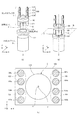
図7、図8は、関連技術を示すもので、この力制御ロボットは、ロボットアーム502、力覚センサ510、エンドエフェクタ501等を有し、エンドエフェクタ501で部品Oを把持してワークQに組み付ける。ロボットアーム502は、駆動装置523によって駆動され、ロボットアーム502の動作信号及び位置制御信号を駆動装置523へ入力する制御装置524が設けられる。
FIGS. 7 and 8 show related technologies. This force control robot has a
力覚センサ510は、ロボットアーム502の先端に取り付けられるアーム側プレート511と、エンドエフェクタ501に取り付けられるエンドエフェクタ側プレート512と、両プレート511、512を結合支持する弾性部材513を有している。力覚センサ510はプレート511、512の間に変位検出機構を備えており、この変位検出機構は、アーム側プレート511にエンドエフェクタ側プレート512へ向けて先端部が十文字形に形成されたビーム514を具備している。
The
上記従来の力制御ロボットでは、ロボットアーム502とエンドエフェクタ501との間に力覚センサ510を直列に配置している。このことから、力覚センサ510の内部に存在するエンドエフェクタ501のロボットアーム502に対する回転中心と、エンドエフェクタ501の重心位置が離れた位置になってしまう。このため、ロボットアーム502を駆動させたときの慣性力によって、弾性部材513の変位支点とエンドエフェクタ501の重心位置の位置差で発生するモーメント力が、力覚センサ510に作用するため、センサ部が静定するまでの時間が長くなる。
In the conventional force control robot, the
この静定時間を短縮するためには、力覚センサ510の弾性部材513の剛性を上げる必要があり、その結果として外力に対してセンサが鈍感になり、力覚センサ510の検出感度の低下を招く。つまり弾性部材の剛性を向上させると高精度な力覚検出が困難になってしまう。このように、従来の構成では、エンドエフェクタの小型化に伴って、センサの検出感度向上と高速化に対応するための剛性の確保等を同時に達成するのが難しかった。
In order to shorten the stabilization time, it is necessary to increase the rigidity of the
本発明は、力覚センサの検出感度の低下を招くことなくエンドエフェクタの小型化が容易であり、しかも高速化にも対応できる力制御ロボットを提供することを目的とするものである。 It is an object of the present invention to provide a force control robot that can easily reduce the size of an end effector without causing a decrease in detection sensitivity of a force sensor, and that can cope with an increase in speed.
本発明の力制御ロボットは、一端が固定端、他端が可動端となるロボットアームと、
前記ロボットアームの前記可動端に弾性部材を介して接続された筐体と、前記筐体に支持され、部品を把持する複数の指モジュールと、前記筐体に支持され、前記複数の指モジュールをそれぞれ独立して駆動する複数の把持駆動部と、を有し、前記ロボットアームに対して回転中心を支点として変位するエンドエフェクタと、
前記弾性部材を挟んでいる前記ロボットアーム及び前記エンドエフェクタのうち一方側に設けられた永久磁石と、他方側に設けられ、前記変位として、前記永久磁石の磁場の強度を検出する変位検出素子と、を有し、前記弾性部材の内側に前記回転中心が存在する力覚センサと、
前記力覚センサで検出した前記変位に基づき前記ロボットアームの動作を制御するロボットアーム制御部と、を備え、
前記複数の把持駆動部は、前記筐体に対して前記複数の指モジュールが配置された側とは反対側であって、前記力覚センサの外側にそれぞれ配置されており、
前記各把持駆動部の重心が、前記回転中心より前記ロボットアーム側に配置されていることを特徴とする。
The force control robot of the present invention includes a robot arm having one end as a fixed end and the other end as a movable end;
A housing connected to the movable end of the robot arm via an elastic member, a plurality of finger modules supported by the housing and gripping parts, and supported by the housing, the plurality of finger modules A plurality of gripping drive units that are independently driven, and an end effector that is displaced with respect to the robot arm as a fulcrum.
A permanent magnet provided on one side of the robot arm and the end effector sandwiching the elastic member, and a displacement detection element provided on the other side for detecting the magnetic field strength of the permanent magnet as the displacement A force sensor in which the center of rotation exists inside the elastic member ;
A robot arm control unit that controls the operation of the robot arm based on the displacement detected by the force sensor,
The plurality of gripping drive units are disposed on the opposite side of the housing from the side on which the plurality of finger modules are disposed, and are disposed outside the force sensor, respectively.
The center of gravity of each gripping drive unit is arranged closer to the robot arm than the center of rotation.
エンドエフェクタの把持駆動部の一部を弾性部材の回転中心よりロボットアーム側に配置することで、センサ剛性の向上と、エンドエフェクタの小型化を可能にする。同時に、ロボットアームを駆動させた時の慣性力で発生するモーメント力が力覚センサに及ぼす影響を低減し、位置決め静定に要する時間を短縮することで、高速化に対応するとともに、ロボットアーム先端部の稼働領域を広げることができる。 By disposing a part of the grip driving unit of the end effector on the robot arm side from the rotation center of the elastic member, it is possible to improve the sensor rigidity and to reduce the size of the end effector. At the same time, the moment force generated by the inertial force when the robot arm is driven reduces the effect on the force sensor, shortens the time required for positioning stabilization, and supports high speed and the tip of the robot arm. The operating area of the department can be expanded.
図1〜図4は、一実施形態による力制御ロボットを示すもので、これは、例えば小型製品における部品を、力制御を行いながら高速で組み付ける産業用のロボットである。図1(a)及び図1(b)の模式図に示すように、エンドエフェクタ1は、部品を把持する把持機構部である複数の指モジュール100と、指モジュールを支持するエンドエフェクタ筐体109と、指モジュールの把持駆動部である複数のモータ105とからなる。図中のエンドエフェクタ筐体109は、支持部プレートと壁部からなる、モータ105及び力覚センサ2を保護する筒状もしくは箱状の部材であるが、説明のため、指モジュール100とモータ105との支持部プレートのみ明示的に描いている。力覚センサ2は、弾性部材130と、外力を受けた際に生じる弾性部材130の変形を検出する検出部170(図3)とを備え、弾性部材130の変形に基づき外力を検出する。例えば歪ゲージ式センサ、もしくは磁気式力覚センサを用いる。
1 to 4 show a force control robot according to an embodiment, which is an industrial robot for assembling components in a small product at high speed while performing force control, for example. As shown in the schematic diagrams of FIGS. 1A and 1B, the
指モジュール100は、指先部材101及び中節部材103と、それらをつなぐ第1関節102及び第2関節104と、を備える。図1(c)はロボットアーム3の長手方向軸Zに対して垂直で、かつ回転中心Cを含む垂直面Bを示している。指モジュールの把持駆動部であるモータ105はエンドエフェクタ筐体109に支持され、図1(c)に示すように第1関節102を駆動するモータ105aと、第2関節104を駆動するモータ105bとで一つの指モジュールを駆動させる。これらは、不図示のコントローラで、それぞれ独立駆動させることが可能で、様々な形状のワークへの把持が可能になっている。なお、図1(c)では、エンドエフェクタ筐体109の壁部のみ明示的に描いている。エンドエフェクタ1は、一端が架台に固定された固定端、他端が可動端となるロボットアーム3に対して、その可動端に、力覚センサ2を介して接続される。図1(a)及び図1(b)に描かれたように、ロボットアーム3の可動端に対してプレート111を介して力覚センサ2を固定してもよい。
The
このような構成をとることによって、組み付け動作などでエンドエフェクタ1に外力が加わった際には、エンドエフェクタ1は、力覚センサ2における弾性部材130の回転中心Cを中心にしてロボットアーム3に対して変位する。ロボットアーム3が長手方向に対して略対称に各部材が構成されている場合には、この回転中心Cはロボットアーム長手方向に直交する断面をとった際、該断面のほぼ中心を通る長手方向軸Z上に存在する。
By adopting such a configuration, when an external force is applied to the
モータ105を支持する筐体であるエンドエフェクタ筐体109は、ロボットアーム3の長手方向軸Zに対し、エンドエフェクタ1の回転中心Cを含む垂直面Bよりもロボットアーム側にモータ105の一部が配置されるように、モータ105を支持している。4本の指モジュール100をそれぞれ駆動するモータ105a、105bは、力覚センサ2の周囲に、長手方向軸Zに対して略対称になるように配置される。
An end effector housing 109, which is a housing for supporting the
本実施形態では、指モジュール100を駆動する複数のモータ105を対称に配置したが、力覚センサ2に対して同心円上に配置しても構わない。また、指モジュール100は、部品や組み付け動作に合わせて、指の本数や関節数などがそれぞれ選ばれ、さまざまな形態のエンドエフェクタ構成をとりうる。
In the present embodiment, the plurality of
図2は、本実施形態のエンドエフェクタの側面図である。図2は、エンドエフェクタ1に対して外力が作用していない状態を示し、紙面に向かって上方を+Z、右方向を+X方向、紙面奥方向を+Yとする。図2において描かれているように、各指モジュール100は、エンドエフェクタ筐体109に支持されており、力覚センサ2の弾性部材130を介して姿勢変化が可能なように構成されている。
FIG. 2 is a side view of the end effector of the present embodiment. FIG. 2 shows a state in which no external force is applied to the
つまり本実施形態における力制御ロボットはエンドエフェクタ1の端部とロボットアーム3の可動端とが、両者とくらべて比較的小さな剛性を有する弾性部材130を有する力覚センサ2にて連結されている状態となっている。したがってエンドエフェクタ1に外力が加わった場合、力覚センサ2の内部に存在する弾性部材130の回転中心Cに対してエンドエフェクタ1は回転することになる。
That is, in the force control robot according to the present embodiment, the end of the
本実施形態の力制御ロボットは、上記回転中心Cに対して重量の大きい把持駆動部であるモータ105の一部をロボットアーム側に配置する点に特徴がある。このような構成をとることで以下詳細に説明するが、力覚センサ2の感度を維持または向上させつつ、エンドエフェクタ1の剛性の低下を抑えることができる。また、モータ105は、エンドエフェクタ1内で、比較的大きな重量をもつため、回転中心Cから把持駆動部であるモータ105の重心が回転中心Cよりロボットアーム側に配置されるとより大きな効果を得ることができる。
The force control robot according to the present embodiment is characterized in that a part of the
図3(a)は、力覚センサ2の構成モデルを示す模式図、図3(b)は図3(a)の断面Bを示す。力覚センサ2は天井部と底部とそれらを繋ぐ柱状部からなり、主に天井部および柱状部が弾性部材130としての役割を担っている。例えば図3(a)に示すように、検出部170の変位検出素子であるホール素子160a、160b、160c、160dは、力覚センサ2の天井部に配置し、検出部170の永久磁石150は力覚センサ2の底部に固定されている。
FIG. 3A is a schematic diagram showing a configuration model of the
エンドエフェクタに外力Fが加わると永久磁石150と各ホール素子の相対変位が発生し、ホール素子160にて検出される磁場の強度が変化する。この磁場の変化量を検出することにより、エンドエフェクタ1のロボットアーム3に対する回転もしくは変位を検知することができる。永久磁石150に対して、変位検出素子であるホール素子160a、160b、160c、160d(合計4個)を弾性部材130の変位側の+X、−X、+Y、−Y位置に対称になる様に、配置することで、変位の大きさとともに変位方向の検出も可能となる。
When an external force F is applied to the end effector, a relative displacement between the
組み付けの際の作用力FがXY平面内で−X、−Y方向にエンドエフェクタに作用したとすると、変位検出素子であるホール素子160a、160b、160c、160dが、永久磁石150に対して、+X、+Y方向に変位する。従って、+X、+Y位置にあるホール素子160a、160bは、永久磁石150に対して遠ざかり、出力が小さくなる。一方、−X、−Y位置にあるホール素子160c、160dは、永久磁石150に近づき、出力は大きくなる。これによって、作用力Fの大きさと方向を検出することができる。なお、永久磁石150と、ホール素子160a、160b、160c、160dの位置関係を逆にしてもよい。また、磁石とホール素子の変位量を検出する方法の代わりに、歪ゲージ方式や静電容量方式で検出部により弾性部材130の変形を検出するように構成された力覚センサを用いてもよい。
Assuming that the acting force F during assembly acts on the end effector in the −X and −Y directions in the XY plane, the
図4は、ロボットアーム3の先端にエンドエフェクタ1を装着した力制御ロボット全体を示すもので、力制御ロボットは、ロボットアーム3と、ロボットアーム3に装着したエンドエフェクタ1と、エンドエフェクタ制御部180と、を有する。エンドエフェクタ1には、エンドエフェクタ1の動作を制御するエンドエフェクタ制御部180が接続され、ここで力覚センサ2より検出した変位信号から力に変換する演算も行う。ロボットアーム3には、ロボットアーム3の動作を制御するロボットアーム制御部210が接続されている。エンドエフェクタ制御部180より、エンドエフェクタ1の指モジュール110に作用する外力の情報をロボットアーム制御部210が受信し、ロボットアーム3の動作に反映させる。
FIG. 4 shows the entire force control robot with the
次に、力制御による組み付け動作を行う一連の流れを、把持した部品Oをワークに組み付ける際に、その組み付け相手であるワークに当接させる場合で説明する。図2に示すように、組み付け時の作用力Fは、指モジュール100を介して、エンドエフェクタ筐体109に伝わり、さらに、力覚センサ2の弾性部材130の回転中心Cを支点にして、弾性部材130が撓む。その時の変位量と向きを力覚センサ2で検出し、検出された変位情報は、エンドエフェクタ制御部180に伝送され、演算器によって作用力Fの大きさと向きに演算され、ロボットアーム制御部210に伝送される。ロボットアーム制御部210では、伝送された作用力Fの情報に基づき、ロボットアーム3の動作を修正しながら組み付けを行う。
Next, a series of flows for performing an assembling operation by force control will be described in a case where the gripped component O is brought into contact with a workpiece that is an assembly partner when the component O is assembled to the workpiece. As shown in FIG. 2, the acting force F at the time of assembly is transmitted to the
図2に示した本実施形態のエンドエフェクタ1の回転中心Cとワークを把持する標準位置である作用点P1までの距離L1とするとする。また図8に示した従来型の構成でのエンドエフェクタの回転中心Cから作用点P2までの距離をL2とする。
Assume that the distance L1 is from the rotation center C of the
図7、8に示された従来の力制御ロボットでは、把持駆動部であるモータも含めてエンドエフェクタ501が力覚センサ510に対して、その端部に固定されている。力覚センサ2の大きさや、永久磁石150と、変位検出素子であるホール素子160の位置関係も同一の条件で比較すると従来の力制御ロボットのほうがその距離が大きくなり、回転中心Cから作用点までの距離の関係が、L1<L2となる。また図2に示すように、組み付け時に発生する組み付け力Fが、外力としてワークを介して、エンドエフェクタ1の作用点P1に作用し、それぞれ変位した時の変位量をδd1とする。一方同条件で、従来の力制御ロボットにおける外力による変位量をδd2とする。
In the conventional force control robot shown in FIGS. 7 and 8, the
この条件下で、外力による力覚センサ2の弾性部材130の変形量が同じだとすると、(永久磁石150と、ホール素子160の変位量δh1、δh2の関係が、δh1=δh2である)、δd1=L1/L2*δd2となる。同じセンサ感度であれば、L1/L2分、変位量δdを抑えることができる。変位量δdが同じであれば、δh1=L2/L1*δh2となり、センサ感度は従来の力制御ロボットと比較して、L2/L1倍に高めることができる。
If the deformation amount of the
図2の構成で回転中心C回りのエンドエフェクタの慣性モーメントをM1、従来の力制御ロボットの構成で回転中心C回りのエンドエフェクタの慣性モーメントをM2とする。本実施形態では、指モジュール100を駆動する把持駆動部であるモータ105の回転中心Cからロボットアーム側に配置される部分の重量分だけ、慣性モーメントが大きくなり、M1<M2となる。
In the configuration of FIG. 2, the inertial moment of the end effector around the rotation center C is M1, and in the configuration of the conventional force control robot, the inertial moment of the end effector around the rotation center C is M2. In the present embodiment, the moment of inertia increases by the weight of the portion disposed on the robot arm side from the rotation center C of the
本実施形態と従来型の構成のエンドエフェクタが有する固有振動数をそれぞれf1、f2とすると、固有振動数fは、f=1/2π*√(k/M)で表わされるため、f1/f2=√(M2/M1)となる。すなわち、本実施形態では、従来型の構成と比較して、√(M2/M1)倍、剛性を高めることが可能となる。このため、ロボットアーム3を動作させたときのエンドエフェクタ1のふらつきを抑えて、位置決め静定時間を短縮し、高速動作への対応が可能となる。つまり把持駆動部であるモータ105が、弾性部材130の回転中心Cよりロボットアーム3側に配置されていることで検出感度向上と高速化に対応するための剛性の確保することができる。
Assuming that the natural frequencies of the end effector of the present embodiment and the conventional type are f1 and f2, respectively, the natural frequency f is expressed by f = 1 / 2π * √ (k / M), and therefore, f1 / f2 = √ (M2 / M1). That is, in this embodiment, the rigidity can be increased by √ (M2 / M1) times as compared with the conventional configuration. For this reason, the wobbling of the
図5及び図6は、本実施形態及び従来型の構成によるエンドエフェクタ1を、組み立てロボットステーションに適用した例を比較するもので、図5は、ロボットステーション301の上面図、図6は側面図である。図5及び図6において、(a)は本実施形態によるエンドエフェクタを適用した例、(b)は従来型の構成によるエンドエフェクタを適用した例を示す。
FIGS. 5 and 6 compare an example in which the
ロボットステーション301は、各辺Xの方形であり、エンドエフェクタ1を、一対のロボットアーム3にそれぞれ装着し、ロボットステーション301の中央付近で、部品Oを双腕で把持して作業する。本実施形態と従来型の構成のエンドエフェクタの全長差をaとすると、ロボットアーム3によるはみ出し量2a分だけロボットステーション301の幅を縮小することができる。さらに、側面図方向では、ロボットアーム3の根元方向側に、エンドエフェクタをbだけ近づけることで、片腕のロボットアーム3の稼働領域を拡大できる。
The
本発明によるエンドエフェクタでは、力覚センサの感度を犠牲にすることなく、センサの高剛性化を図ることができるため組み立て用ロボット等に好適に適用できる。 Since the end effector according to the present invention can increase the rigidity of the sensor without sacrificing the sensitivity of the force sensor, it can be suitably applied to an assembly robot or the like.
1 エンドエフェクタ
2 力覚センサ
3 ロボットアーム
100 指モジュール
105、105a、105b モータ
130 弾性部材
301 ロボットステーション
DESCRIPTION OF
Claims (3)
前記ロボットアームの前記可動端に弾性部材を介して接続された筐体と、前記筐体に支持され、部品を把持する複数の指モジュールと、前記筐体に支持され、前記複数の指モジュールをそれぞれ独立して駆動する複数の把持駆動部と、を有し、前記ロボットアームに対して回転中心を支点として変位するエンドエフェクタと、
前記弾性部材を挟んでいる前記ロボットアーム及び前記エンドエフェクタのうち一方側に設けられた永久磁石と、他方側に設けられ、前記変位として、前記永久磁石の磁場の強度を検出する変位検出素子と、を有し、前記弾性部材の内側に前記回転中心が存在する力覚センサと、
前記力覚センサで検出した前記変位に基づき前記ロボットアームの動作を制御するロボットアーム制御部と、を備え、
前記複数の把持駆動部は、前記筐体に対して前記複数の指モジュールが配置された側とは反対側であって、前記力覚センサの外側にそれぞれ配置されており、
前記各把持駆動部の重心が、前記回転中心より前記ロボットアーム側に配置されていることを特徴とする力制御ロボット。 A robot arm with one end fixed and the other end movable;
A housing connected to the movable end of the robot arm via an elastic member, a plurality of finger modules supported by the housing and gripping parts, and supported by the housing, the plurality of finger modules A plurality of gripping drive units that are independently driven, and an end effector that is displaced with respect to the robot arm as a fulcrum.
A permanent magnet provided on one side of the robot arm and the end effector sandwiching the elastic member, and a displacement detection element provided on the other side for detecting the magnetic field strength of the permanent magnet as the displacement A force sensor in which the center of rotation exists inside the elastic member ;
A robot arm control unit that controls the operation of the robot arm based on the displacement detected by the force sensor,
The plurality of gripping drive units are disposed on the opposite side of the housing from the side on which the plurality of finger modules are disposed, and are disposed outside the force sensor, respectively.
The force control robot according to claim 1, wherein a center of gravity of each gripping drive unit is disposed closer to the robot arm than the center of rotation.
前記各把持駆動部は、前記複数の関節をそれぞれ駆動する複数のモータを備えていることを特徴とする請求項1に記載の力制御ロボット。 Each finger module has a plurality of joints,
The force control robot according to claim 1, wherein each of the grip driving units includes a plurality of motors that respectively drive the plurality of joints.
Priority Applications (1)
| Application Number | Priority Date | Filing Date | Title |
|---|---|---|---|
| JP2011112271A JP5911203B2 (en) | 2010-05-20 | 2011-05-19 | Force control robot |
Applications Claiming Priority (3)
| Application Number | Priority Date | Filing Date | Title |
|---|---|---|---|
| JP2010116436 | 2010-05-20 | ||
| JP2010116436 | 2010-05-20 | ||
| JP2011112271A JP5911203B2 (en) | 2010-05-20 | 2011-05-19 | Force control robot |
Publications (3)
| Publication Number | Publication Date |
|---|---|
| JP2012000746A JP2012000746A (en) | 2012-01-05 |
| JP2012000746A5 JP2012000746A5 (en) | 2014-06-26 |
| JP5911203B2 true JP5911203B2 (en) | 2016-04-27 |
Family
ID=44626951
Family Applications (1)
| Application Number | Title | Priority Date | Filing Date |
|---|---|---|---|
| JP2011112271A Expired - Fee Related JP5911203B2 (en) | 2010-05-20 | 2011-05-19 | Force control robot |
Country Status (3)
| Country | Link |
|---|---|
| US (1) | US9095984B2 (en) |
| JP (1) | JP5911203B2 (en) |
| WO (1) | WO2011145713A1 (en) |
Families Citing this family (15)
| Publication number | Priority date | Publication date | Assignee | Title |
|---|---|---|---|---|
| JP2011200943A (en) * | 2010-03-24 | 2011-10-13 | Canon Inc | Force control robot |
| JP5936374B2 (en) * | 2011-02-15 | 2016-06-22 | キヤノン株式会社 | Piezoelectric vibration type force sensor, robot hand and robot arm |
| KR101912716B1 (en) * | 2011-11-01 | 2018-10-30 | 삼성전자주식회사 | Robot arm including force sensing apparatus |
| JP5896123B2 (en) * | 2012-01-23 | 2016-03-30 | 株式会社Ihi | Tool control method and apparatus |
| US9739674B2 (en) * | 2015-01-09 | 2017-08-22 | Stryker Corporation | Isolated force/torque sensor assembly for force controlled robot |
| KR101734241B1 (en) * | 2015-12-10 | 2017-05-11 | 현대자동차 주식회사 | Trunk lid hinge intellectual loader unit |
| CN105751231B (en) * | 2016-04-29 | 2018-12-28 | 广州达意隆包装机械股份有限公司 | A kind of robot end's press feedback device |
| DE102018201652B3 (en) | 2018-02-02 | 2019-06-13 | Kuka Deutschland Gmbh | robot tool |
| US11565403B2 (en) | 2018-10-09 | 2023-01-31 | Canon Kabushiki Kaisha | Attaching mechanism, robot apparatus, and attaching method |
| DE102018126250A1 (en) * | 2018-10-22 | 2020-04-23 | Kuka Systems Gmbh | Assembly tool and assembly method |
| JP6853231B2 (en) * | 2018-11-19 | 2021-03-31 | ファナック株式会社 | Gripping device and system |
| CN112672861A (en) * | 2019-03-22 | 2021-04-16 | 欧姆龙株式会社 | Robot, robot control method, and program |
| CN113400072A (en) * | 2021-06-26 | 2021-09-17 | 山东省智能机器人应用技术研究院 | End effector and system for grabbing caterpillar link based on 3D vision |
| CN114083563B (en) * | 2021-11-15 | 2023-09-19 | 中铁电气化局集团有限公司 | Combined carrier cable seat grabbing manipulator |
| CN114029934B (en) * | 2021-12-11 | 2023-08-15 | 浙江工业大学 | Universal active radial compliant constant force end effector and working method thereof |
Family Cites Families (12)
| Publication number | Priority date | Publication date | Assignee | Title |
|---|---|---|---|---|
| US3984006A (en) * | 1974-02-01 | 1976-10-05 | Hitachi, Ltd. | Automatic assembly control system |
| JPS61241083A (en) | 1985-04-18 | 1986-10-27 | 三菱重工業株式会社 | Method of controlling position of handling |
| JPH0640039B2 (en) * | 1985-09-10 | 1994-05-25 | オムロン株式会社 | Force detector |
| JPH06226671A (en) * | 1993-02-02 | 1994-08-16 | Mazda Motor Corp | Robot hand control device |
| US5378033A (en) * | 1993-05-10 | 1995-01-03 | University Of Kentucky Research Foundation | Multi-function mechanical hand with shape adaptation |
| JPH09258814A (en) * | 1996-03-22 | 1997-10-03 | Kayaba Ind Co Ltd | Device and method for controlling position of assembling robot |
| JP3970640B2 (en) * | 2002-03-05 | 2007-09-05 | 本田技研工業株式会社 | 6-axis force sensor |
| JP2005349490A (en) * | 2004-06-08 | 2005-12-22 | Sharp Corp | Multi-flexible multi-finger hand |
| JP2009148846A (en) * | 2007-12-19 | 2009-07-09 | Tokyo Institute Of Technology | Gripping mechanism |
| JP2010131743A (en) * | 2008-10-30 | 2010-06-17 | Canon Inc | Gripping device including force sensor |
| JP5663828B2 (en) | 2008-11-11 | 2015-02-04 | 東洋製罐株式会社 | Water absorbent resin composition |
| JP5679711B2 (en) | 2010-07-06 | 2015-03-04 | キヤノン株式会社 | Robot system and gripping method |
-
2011
- 2011-05-13 US US13/696,633 patent/US9095984B2/en not_active Expired - Fee Related
- 2011-05-13 WO PCT/JP2011/061603 patent/WO2011145713A1/en active Application Filing
- 2011-05-19 JP JP2011112271A patent/JP5911203B2/en not_active Expired - Fee Related
Also Published As
| Publication number | Publication date |
|---|---|
| US20130054027A1 (en) | 2013-02-28 |
| US9095984B2 (en) | 2015-08-04 |
| WO2011145713A1 (en) | 2011-11-24 |
| WO2011145713A4 (en) | 2012-02-09 |
| JP2012000746A (en) | 2012-01-05 |
Similar Documents
| Publication | Publication Date | Title |
|---|---|---|
| JP5911203B2 (en) | Force control robot | |
| US9975250B2 (en) | Force detecting device, robot, electronic component conveying apparatus | |
| US10618175B2 (en) | Vibration measurement method for moving part, vibration measurement method for robot, and control device | |
| WO2011117944A1 (en) | Force control robot | |
| EP2407767B1 (en) | Biaxial tensile testing machine | |
| JP5717797B2 (en) | Robot hand for conveying article, robot and robot system provided with robot hand, and control method of robot hand | |
| JP2010131743A (en) | Gripping device including force sensor | |
| US10239213B1 (en) | Flexure assembly for force/torque sensing | |
| CN103991084A (en) | Robot hand | |
| KR20150037567A (en) | Micromachined gyroscope including a guided mass system | |
| JP2015059793A (en) | Lever type measurement tool | |
| US10279468B2 (en) | Industrial robot for performing processing on works | |
| KR101050229B1 (en) | Robot hand with torque sensor | |
| JP6507094B2 (en) | manipulator | |
| JP2012076188A (en) | Parallel link mechanism and driving stage | |
| WO2018003692A1 (en) | Physical quantity sensor | |
| JP2013052487A (en) | Parallel mechanism and positioning device using parallel mechanism | |
| CN112140105B (en) | robot | |
| JP6304402B2 (en) | Improved gyroscope structure and gyroscope device | |
| JP4888375B2 (en) | Robot hand | |
| JP4687085B2 (en) | Compound sensor | |
| JP2013107138A (en) | Robot and method for controlling robot | |
| US10634698B2 (en) | High-precision scanning device | |
| WO2022163536A1 (en) | Displacement detecting sensor, control device, and control system | |
| JP6278620B2 (en) | Active compliance equipment |
Legal Events
| Date | Code | Title | Description |
|---|---|---|---|
| RD03 | Notification of appointment of power of attorney |
Free format text: JAPANESE INTERMEDIATE CODE: A7423 Effective date: 20120203 |
|
| RD04 | Notification of resignation of power of attorney |
Free format text: JAPANESE INTERMEDIATE CODE: A7424 Effective date: 20130228 |
|
| A521 | Request for written amendment filed |
Free format text: JAPANESE INTERMEDIATE CODE: A523 Effective date: 20140509 |
|
| A621 | Written request for application examination |
Free format text: JAPANESE INTERMEDIATE CODE: A621 Effective date: 20140509 |
|
| A977 | Report on retrieval |
Free format text: JAPANESE INTERMEDIATE CODE: A971007 Effective date: 20150212 |
|
| A131 | Notification of reasons for refusal |
Free format text: JAPANESE INTERMEDIATE CODE: A131 Effective date: 20150310 |
|
| A521 | Request for written amendment filed |
Free format text: JAPANESE INTERMEDIATE CODE: A523 Effective date: 20150511 |
|
| A02 | Decision of refusal |
Free format text: JAPANESE INTERMEDIATE CODE: A02 Effective date: 20151020 |
|
| A521 | Request for written amendment filed |
Free format text: JAPANESE INTERMEDIATE CODE: A523 Effective date: 20160120 |
|
| A911 | Transfer to examiner for re-examination before appeal (zenchi) |
Free format text: JAPANESE INTERMEDIATE CODE: A911 Effective date: 20160201 |
|
| TRDD | Decision of grant or rejection written | ||
| A01 | Written decision to grant a patent or to grant a registration (utility model) |
Free format text: JAPANESE INTERMEDIATE CODE: A01 Effective date: 20160301 |
|
| A61 | First payment of annual fees (during grant procedure) |
Free format text: JAPANESE INTERMEDIATE CODE: A61 Effective date: 20160329 |
|
| R151 | Written notification of patent or utility model registration |
Ref document number: 5911203 Country of ref document: JP Free format text: JAPANESE INTERMEDIATE CODE: R151 |
|
| LAPS | Cancellation because of no payment of annual fees |