JP6713402B2 - Paper take-up mechanism - Google Patents
Paper take-up mechanism Download PDFInfo
- Publication number
- JP6713402B2 JP6713402B2 JP2016202301A JP2016202301A JP6713402B2 JP 6713402 B2 JP6713402 B2 JP 6713402B2 JP 2016202301 A JP2016202301 A JP 2016202301A JP 2016202301 A JP2016202301 A JP 2016202301A JP 6713402 B2 JP6713402 B2 JP 6713402B2
- Authority
- JP
- Japan
- Prior art keywords
- winding
- paper
- tapered
- shaft portion
- winding shaft
- Prior art date
- Legal status (The legal status is an assumption and is not a legal conclusion. Google has not performed a legal analysis and makes no representation as to the accuracy of the status listed.)
- Active
Links
Images

Landscapes
- Labeling Devices (AREA)
- Winding Of Webs (AREA)
Description
本発明は、長尺の帯状の用紙を巻き取るための用紙巻取り機構に関する。 The present invention relates to a paper winding mechanism for winding a long strip of paper.
長尺の帯状の用紙(例えばラベル剥離後のラベル台紙等)を巻き取るための用紙巻取り機構として種々のものが提案されている。
(i)特開平10−250885号公報に記載のものでは、台紙巻取部を周方向に分割された複数の円筒部材から構成して、各円筒部材の内面に小径部および大径部をそれぞれ形成し、操作部材が小径部に嵌合したときに各円筒部材を巻き取り径に保持して台紙の巻き取りを行うとともに、台紙の巻き取り後は、操作部材を各円筒部材の大径部に嵌合させて各円筒部材の巻き取り径を縮径させることにより、各円筒部材に巻き取られた台紙を各円筒部材の一端側から引き抜けるようにしている(同公報の段落[0043]〜[0044]、図1および図7参照)。
Various types of paper winding mechanisms have been proposed for winding a long strip-shaped paper (for example, a label mount after peeling a label).
(I) In the one disclosed in Japanese Patent Application Laid-Open No. 10-250885, the mount paper winding section is composed of a plurality of cylindrical members divided in the circumferential direction, and a small diameter portion and a large diameter portion are provided on the inner surface of each cylindrical member. When the operating member is fitted into the small diameter portion, the cylindrical member is held at the winding diameter to wind the mount, and after the mount is wound, the operating member is moved to the large diameter portion of each cylindrical member. The cylindrical base member is fitted into the cylindrical member to reduce the winding diameter of the cylindrical member, so that the mount paper wound around the cylindrical member can be pulled out from one end side of each cylindrical member (paragraph [0043] to [0044], see FIGS. 1 and 7.).
(ii)特開2009−203029号公報に記載のものでは、巻き取り軸を、一端がフランジ部に固定された固定軸と、固定軸の外周側に対向配置された軸方向移動可能な一対の平板状の可動片とから構成し、各可動片の一端を固定軸の他端側に形成された大径の可動片支持部に係合させた状態で台紙の巻き取りを行うとともに、台紙の巻取り後は、各可動片をフランジ部側から軸方向に引っ張って各可動片の一端と固定軸の他端側の可動片支持部との係合状態を解除して巻き取り径を縮径させることにより、巻き取り軸に巻き取った台紙を巻き取り軸から取り外すようにしている(同公報の段落[0060]、[0062]〜[0064]、図6および図9参照)。 (Ii) In the one described in Japanese Patent Application Laid-Open No. 2009-203029, the winding shaft includes a fixed shaft whose one end is fixed to the flange portion, and a pair of axially movable members which are arranged to face each other on the outer peripheral side of the fixed shaft. It is composed of a flat plate-shaped movable piece, and while the one end of each movable piece is engaged with the large-diameter movable piece support portion formed on the other end side of the fixed shaft, the mount is wound and After winding, pull each movable piece from the flange side in the axial direction to release the engagement state between one end of each movable piece and the movable piece support on the other end side of the fixed shaft to reduce the winding diameter. By doing so, the mount paper wound around the winding shaft is removed from the winding shaft (see paragraphs [0060], [0062] to [0064], and FIGS. 6 and 9 of the publication).
(iii)特開昭63−165257号公報に記載のものでは、各々略半円筒状の一対の巻取コアを円筒状に組み付けて巻取部を構成し、巻取部の内部に軸方向に延びかつ一端に操作レバーを有するボス部を挿通させ、ボス部外周の複数のカム部を巻取コア内周の複数のカム圧接部にそれぞれ圧接させて巻取部を拡径させた状態で台紙の巻き取りを行うとともに、巻取り後は、操作レバーを操作してボス部外周の各カム部と巻取コア内周の各カム圧接部との圧接状態を解除して各巻取コアの巻き取り径を縮径させることにより、各巻取コアに巻き付けられた台紙を各巻取コアから取り外すようにしている(同公報の第2頁左上欄第19行〜同頁右上欄第8行、同頁左下欄第7〜12行、同頁同欄第19行〜同頁右下欄第3行、第3頁左上欄第5〜13行、第1図、第2図および第4図〜第7図参照)。
(Iii) In the one disclosed in JP-A-63-165257, a pair of winding cores each having a substantially semi-cylindrical shape are assembled into a cylindrical shape to form a winding portion, and the winding portion is axially arranged inside the winding portion. Insert the boss part that extends and has the operation lever at one end, and press the cam parts on the outer circumference of the boss into the cam contact parts on the inner circumference of the winding core to expand the diameter of the winding part. After winding up, operate the operation lever and release the pressure contact state between each cam on the outer circumference of the boss and each cam pressure contact on the inner circumference of the winding core to wind up each winding core. By reducing the diameter, the mount wrapped around each winding core is removed from each winding core (page 19, upper left column, line 19 to upper right column, line 8 of the same publication, lower left of the same page). Column lines 7 to 12, same column, line 19 to same page lower right column, third line,
(iv)特開2010−1082号公報に記載のものでは、台紙巻取り軸を、基体と、これに接近離反自在な移動体とから構成し、台紙巻取り軸の内部に軸方向に延びかつ一端に操作ノブを有する押体を挿通させ、押体外周の複数のカムを移動体内周の複数のカムフォロアにそれぞれ圧接させ移動体を基体から離反させて台紙巻取り軸を拡径させた状態で台紙の巻き取りを行うとともに、巻取り後は、操作ノブを操作して押体外周の各カムと移動体内周の各カムフォロアとの圧接状態を解除し移動体を基体に接近させて台紙巻取り軸の巻き取り径を縮径させることにより、台紙巻取り軸に巻き付けられた台紙を台紙巻取り軸から取り外すようにしている(同公報の段落[0022]、[0023]、[0036]、[0045]、図4および図5参照)。 (Iv) In the one disclosed in Japanese Patent Application Laid-Open No. 2010-1082, the mount paper winding shaft is composed of a base body and a movable body that can move toward and away from the base material, and extends in the axial direction inside the mount paper winding shaft. Insert the pusher with the operation knob at one end, press the cams on the outer circumference of the pusher against the cam followers on the inner circumference of the moving body, move the moving body away from the base, and expand the diameter of the board winding shaft. While winding the mount, after winding, operate the operation knob to release the pressure contact state between each cam on the outer circumference of the pusher and each cam follower on the inner circumference of the moving body, and move the moving body closer to the substrate to wind up the mount. By reducing the winding diameter of the shaft, the mount wound around the mount winding shaft is removed from the mount winding shaft (paragraphs [0022], [0023], [0036], [ 0045], see FIGS. 4 and 5.
しかしながら、前掲(i)の特開平10−250885号公報に記載のものでは、台紙巻取部を構成する各円筒部材の巻き取り径が縮径されるのは、あくまで各円筒部材の一端側のみであり、他端側は縮径されない(すなわち、台紙の幅方向全体にわたって縮径されるのではない)。したがって、長尺の台紙が各円筒部材に厚く巻き付けられて相当の巻付圧が各円筒部材の外面に作用している状態では、とくに、縮径されていない台紙巻取部の他端側において台紙を引き出す際に大きな力を必要とし、その結果、巻取り後のロール状の台紙の取外しを簡単かつ速やかに行えない場合が生じる。 However, in the above-mentioned (i) Japanese Patent Laid-Open No. 10-250885, the winding diameter of each cylindrical member constituting the mount winding unit is reduced only to one end side of each cylindrical member. And the other end side is not reduced in diameter (that is, it is not reduced in the entire width direction of the mount). Therefore, in the state where the long mount is thickly wound around each cylindrical member and a considerable wrapping pressure is applied to the outer surface of each cylindrical member, especially on the other end side of the unwrapped mount winding unit. A large force is required to pull out the mount, and as a result, there are cases where the roll-shaped mount after winding cannot be easily and quickly removed.
同様に、前掲(ii)の特開2009−203029号公報に記載のものにおいても、巻き取り軸の巻き取り径が縮径されるのは、あくまで各可動片の一端側のみであり、他端側は縮径されない(すなわち、台紙の幅方向全体にわたっては縮径されるのではない)。したがって、長尺の台紙が固定軸および各可動片に厚く巻き付けられて相当の巻付圧が各可動片の外面に作用している状態では、とくに、縮径されていない各可動片の他端側において台紙を引き出す際に大きな力を必要とし、その結果、巻取り後のロール状の台紙の取外しを簡単かつ速やかに行えない場合が生じる。 Similarly, in the above-mentioned (ii) Japanese Patent Application Laid-Open No. 2009-203029, the winding diameter of the winding shaft is reduced only to one end side of each movable piece, and the other end. The sides are not reduced in diameter (ie, they are not reduced across the width of the mount). Therefore, in the state where the long mount is thickly wound around the fixed shaft and each movable piece and a considerable winding pressure acts on the outer surface of each movable piece, the other end of each unmoved movable piece is A large force is required to pull out the mount on the side, and as a result, there are cases where the roll-shaped mount after winding cannot be easily and quickly removed.
また、前掲(iii)の特開昭63−165257号公報に記載のものでは、前掲(i)および(ii)のものとは異なり、台紙の幅方向全体にわたって巻き取り径を縮径することは一応可能ではあるが、縮径の操作の際には、巻取コア内周の各カム圧接部に強固に圧接して局所的に喰い込んだボス部外周の各カム部の圧接状態を操作レバーを回転操作することで解除する必要があり、その際、各巻取コアの外周面に巻き取られた長尺の台紙から当該外周面に相当の巻付圧が作用していることと相俟って、操作レバーの操作には非常に大きな力を必要とし、その結果、巻取り後のロール状の台紙の取外しを簡単かつ速やかに行えない場合が生じる。 Further, in the above-mentioned (iii) Japanese Patent Laid-Open No. 63-165257, unlike the above-mentioned (i) and (ii), the winding diameter can be reduced over the entire width direction of the mount. Although it is possible for the time being, when the diameter is reduced, the operation lever is set to the pressure contact state of each cam portion on the outer circumference of the boss that is locally pressed by firmly contacting each cam pressure contact portion on the inner circumference of the winding core. It is necessary to release it by rotating it, and at that time, in combination with the fact that a considerable amount of wrapping pressure is applied to the outer peripheral surface of the winding core from the long mount wound on the outer peripheral surface. As a result, a very large force is required to operate the operation lever, and as a result, there are cases in which the roll-shaped mount after winding cannot be easily and quickly removed.
前掲(iv)の特開2010−1082号公報に記載のものでは、同様に、前掲(i)および(ii)のものとは異なり、台紙の幅方向全体にわたって巻き取り径を縮径することは一応可能ではあるが、縮径の操作の際には、移動体内周の各カムフォロアに強固に圧接して局所的に喰い込んだ押体外周の各カムの圧接状態を操作ノブを引き出し操作することで解除する必要があり、その際、台紙巻取り軸の外周面に巻き取られた長尺の台紙から当該外周面に相当の巻付圧が作用していることと相俟って、操作ノブの操作には非常に大きな力を必要とし、その結果、巻取り後のロール状の台紙の取外しを簡単かつ速やかに行えない場合が生じる。 Similarly to the above (iv) JP-A-2010-1082, unlike the above (i) and (ii), the winding diameter can be reduced over the entire width direction of the mount. Although it is possible for the time being, when reducing the diameter, operate the operation knob by pulling out the pressure contact state of each cam on the outer circumference of the pusher that firmly pressed against each cam follower on the inner circumference of the moving body and locally caught. It is necessary to release it with the operation knob in conjunction with the fact that a considerable amount of wrapping pressure acts on the outer peripheral surface of the long mount that is wound around the outer surface of the mount winding shaft. The above operation requires a very large force, and as a result, there are cases where the roll-shaped backing sheet cannot be easily and quickly removed after winding.
本発明は、このような従来の実情に鑑みてなされたもので、本発明が解決しようとする課題は、長尺の帯状の用紙を巻き取った後のロール状用紙の取外しを簡単かつ速やかに行える用紙巻取り機構を提供することにある。また、本発明は、長尺の帯状の用紙の巻取り始端を簡単かつ確実に保持できる用紙巻取り機構を実現しようとしている。 The present invention has been made in view of such conventional circumstances, and the problem to be solved by the present invention is to easily and quickly remove a roll-shaped paper after winding a long strip-shaped paper. An object of the present invention is to provide a paper winding mechanism that can be used. Further, the present invention is intended to realize a paper winding mechanism that can easily and reliably hold the winding start end of a long strip of paper.
本発明に係る用紙巻取り機構は、長尺の帯状の用紙を巻き取るための機構であって、用紙が巻き付けられる外周面を有しかつ外周面の一部にポケット穴が形成された巻取り軸部と、ポケット穴に収容されるとともに、ポケット穴の外側に配置されかつ用紙の幅方向全体にわたって延在する外側面、および、ポケット穴の内側に配置されかつ軸方向にテーパ状に延びるテーパ状内側面を有し、ポケット穴からの外側面の突出量が変化するようにポケット穴内で半径方向に移動自在な内側テーパ部材と、内側テーパ部材のテーパ状内側面に対応しかつ係合し得るテーパ状外側面を有し、内側テーパ部材を半径方向に移動させるように軸方向に移動自在な外側テーパ部材とを備え、巻取り軸部が、外周面に開口しかつ軸方向に延びるスリットを介して離隔配置された第1、第2の巻取り軸部から構成されるとともに、第1の巻取り軸部が、外周面の一部に形成された第1のポケット穴と、スリットに開口する第2のポケット穴とを有し、第1、第2のポケット穴にそれぞれ第1、第2の内側テーパ部材が収容されており、外側テーパ部材が、第1、第2の内側テーパ部材の第1、第2のテーパ状内側面にそれぞれ対応しかつ係合し得る第1、第2のテーパ状外側面を有しており、用紙の始端がスリット内において第2の内側テーパ部材の外側面と第2の巻取り軸部との間で把持されるようになっている。 A paper winding mechanism according to the present invention is a mechanism for winding a long strip-shaped paper, and has a peripheral surface around which the paper is wound and a pocket hole is formed in a part of the peripheral surface. A shaft portion, an outer surface that is accommodated in the pocket hole, is disposed outside the pocket hole, and extends over the entire width direction of the paper; and a taper that is disposed inside the pocket hole and axially extends in a taper shape. A tapered inner side surface of the inner tapered member and an inner tapered member that has a curved inner side surface and is movable in the pocket hole in the radial direction so that the protruding amount of the outer side surface from the pocket hole changes. A slit having an outer taper outer surface and an outer taper member that is axially movable so as to move the inner taper member in the radial direction, and the winding shaft portion is open to the outer peripheral surface and extends in the axial direction. The first and second winding shaft portions are separated from each other by the first and second winding shaft portions, and the first winding shaft portion has a slit and a first pocket hole formed in a part of the outer peripheral surface. A second pocket hole that is open, the first and second inner taper members are housed in the first and second pocket holes, respectively, and the outer taper member is the first and second inner taper members. A first inner side taper member having first and second tapered outer side surfaces corresponding to and engaging with the first and second tapered inner side surfaces of the member, respectively, and the leading end of the sheet is a second inner taper member within the slit. It is designed to be gripped between the outer side surface of the and the second winding shaft portion.
本発明によれば、用紙を巻取り軸部に巻き取る際には、内側テーパ部材が半径方向外方に移動して内側テーパ部材のポケット穴からの突出量が大きくなるように外側テーパ部材を軸方向に移動させた状態で、用紙を巻取り軸部の外周面および内側テーパ部材の外側面に巻き付ける一方、用紙の巻取り後は、内側テーパ部材が半径方向内方に移動して内側テーパ部材のポケット穴からの突出量が小さくなるように外側テーパ部材を軸方向に移動させることで、巻取り軸部の外周面および内側テーパ部材の外側面による巻き取り径を用紙の幅方向全体にわたって縮径させることができるので、巻取り軸部の外周面および内側テーパ部材の外側面に巻き取られた用紙を巻取り軸部から簡単に取り外すことができる。しかも、この場合には、外側テーパ部材が内側テーパ部材のテーパ状内側面に対応するテーパ状外側面を有していることで、外側テーパ部材のテーパ状外側面および内側テーパ部材のテーパ状内側面がそれぞれくさび面として面接触するので、内側テーパ部材の半径方向移動を比較的小さな力で行うことができ、これにより、巻取り軸部からの用紙の取外しを速やかに行うことができる。 According to the present invention, when the paper is wound around the winding shaft portion, the outer taper member is moved so that the inner taper member moves outward in the radial direction and the protrusion amount from the pocket hole of the inner taper member increases. While the paper is being moved in the axial direction, the paper is wound around the outer peripheral surface of the take-up shaft and the outer surface of the inner taper member, while after the paper is taken up, the inner taper member moves radially inward to taper the inner taper By moving the outer taper member in the axial direction so that the amount of protrusion of the member from the pocket hole becomes small, the winding diameter by the outer peripheral surface of the winding shaft portion and the outer surface of the inner taper member is spread over the entire width direction of the paper. Since the diameter can be reduced, the paper wound on the outer peripheral surface of the winding shaft portion and the outer surface of the inner taper member can be easily removed from the winding shaft portion. Moreover, in this case, the outer tapered member has the tapered outer surface corresponding to the inner tapered surface of the inner tapered member, so that the outer tapered surface of the outer tapered member and the inner tapered surface of the inner tapered member are Since the side surfaces are in contact with each other as wedge surfaces, the inner taper member can be moved in the radial direction with a comparatively small force, whereby the paper can be quickly removed from the winding shaft portion.
また、本発明においては、スリットを介して離隔配置された第1、第2の巻取り軸部から巻取り軸部が構成されるとともに、第1の巻取り軸部が、外周面の一部に形成された第1のポケット穴と、スリットに開口する第2のポケット穴とを有し、第1、第2のポケット穴にそれぞれ第1、第2の内側テーパ部材が収容されており、外側テーパ部材が、第1、第2の内側テーパ部材の第1、第2のテーパ状内側面にそれぞれ対応しかつ係合し得る第1、第2のテーパ状外側面を有しており、用紙の始端がスリット内において第2の内側テーパ部材の外側面と第2の巻取り軸部との間で把持されるようになっている。 Further, in the present invention, the winding shaft portion is composed of the first and second winding shaft portions that are spaced apart from each other through the slit, and the first winding shaft portion is a part of the outer peripheral surface. A first pocket hole formed in the slit and a second pocket hole opening to the slit, and the first and second pocket holes respectively accommodate the first and second inner taper members, The outer taper member has first and second tapered outer surfaces corresponding to and engageable with the first and second tapered inner surfaces of the first and second inner tapered members, respectively. start of the sheet that has come to be gripped between the outer surface and the second winding shaft portion of the second inner tapered member in the slit.
本発明によれば、用紙を巻取り軸部に巻き取る際には、第1の内側テーパ部材が半径方向外方に移動して第1の内側テーパ部材の第1のポケット穴からの突出量が大きくなるように外側テーパ部材を軸方向に移動させた状態で、用紙を第1、第2の巻取り軸部の外周面および第1の内側テーパ部材の外側面に巻き付ける一方、用紙の巻取り後は、第1の内側テーパ部材が半径方向内方に移動して第1の内側テーパ部材の第1のポケット穴からの突出量が小さくなるように外側テーパ部材を軸方向に移動させることで、第1、第2の巻取り軸部の外周面および第1の内側テーパ部材の外側面による巻き取り径を用紙の幅方向全体にわたって縮径させることができるので、第1、第2の巻取り軸部の外周面および第1の内側テーパ部材の外側面に巻き取られた用紙を第1、第2の巻取り軸部から簡単に取り外すことができる。しかも、この場合には、外側テーパ部材が第1の内側テーパ部材の第1のテーパ状内側面に対応する第1のテーパ状外側面を有していることで、外側テーパ部材の第1のテーパ状外側面および第1の内側テーパ部材の第1のテーパ状内側面がそれぞれくさび面として面接触するので、第1の内側テーパ部材の半径方向移動を比較的小さな力で行うことができ、これにより、第1、第2の巻取り軸部からの用紙の取外しを速やかに行うことができる。 According to the present invention, when the paper is wound around the winding shaft portion, the first inner taper member moves outward in the radial direction and the protrusion amount of the first inner taper member from the first pocket hole. While the outer taper member is moved in the axial direction so as to increase, the paper is wound around the outer peripheral surfaces of the first and second take-up shaft portions and the outer surface of the first inner taper member, while the paper is wound. After the removal, the outer taper member is moved in the axial direction so that the first inner taper member moves inward in the radial direction and the protrusion amount of the first inner taper member from the first pocket hole becomes small. Since the winding diameters of the outer peripheral surfaces of the first and second winding shaft portions and the outer surface of the first inner taper member can be reduced over the entire width direction of the sheet, the first and second The paper wound around the outer peripheral surface of the winding shaft portion and the outer surface of the first inner taper member can be easily removed from the first and second winding shaft portions. Moreover, in this case, the outer tapered member has the first tapered outer surface corresponding to the first tapered inner surface of the first inner tapered member, so that the first tapered outer surface of the outer tapered member is Since the tapered outer surface and the first inner tapered surface of the first inner tapered member are in surface contact with each other as wedge surfaces, the radial movement of the first inner tapered member can be performed with a relatively small force, Thereby, the paper can be quickly removed from the first and second take-up shaft portions.
さらに、本発明によれば、用紙を巻取り軸部に巻き取り始める際には、用紙の始端を第1、第2の巻取り軸部間のスリットを通して第2の内側テーパ部材の外側面と第2の巻取り軸部との間に挿入する。この状態から、第1の内側テーパ部材の第1のポケット穴からの突出量が大きくなるように外側テーパ部材を軸方向に移動させると、第2の内側テーパ部材の第2のポケット穴からの突出量も同様に大きくなり、これにより、用紙の始端を第2の内側テーパ部材の外側面と第2の巻取り軸部との間で簡単かつ確実に保持できる。一方、用紙の巻取り後は、第1の内側テーパ部材の第1のポケット穴からの突出量が小さくなるように外側テーパ部材を軸方向に移動させると、第2の内側テーパ部材の第2のポケット穴からの突出量も同様に小さくなり、その結果、第2の内側テーパ部材の外側面と第2の巻取り軸部との間で把持されていた用紙の始端の把持状態が解除される。これにより、用紙の始端を第1、第2の巻取り軸部の間のスリットから簡単に取り外すことができる。 Further, according to the present invention, when starting to wind the paper on the take-up shaft portion, the starting end of the paper is passed through the slit between the first and second take-up shaft portions to the outer surface of the second inner taper member. It is inserted between the second winding shaft portion. From this state, when the outer taper member is moved in the axial direction so that the protrusion amount of the first inner taper member from the first pocket hole is increased, the second inner taper member is moved from the second pocket hole. The amount of protrusion is also increased, and thus the starting end of the sheet can be easily and reliably held between the outer surface of the second inner taper member and the second winding shaft portion. On the other hand, after the paper is wound up, if the outer taper member is moved in the axial direction so that the protrusion amount of the first inner taper member from the first pocket hole is reduced, the second inner taper member becomes Similarly, the amount of protrusion from the pocket hole of the sheet is also reduced, and as a result, the gripped state of the leading edge of the sheet that was gripped between the outer surface of the second inner taper member and the second winding shaft portion is released. It Thereby, the starting end of the sheet can be easily removed from the slit between the first and second winding shaft portions.
このように、本発明によれば、外側テーパ部材の軸方向移動により、第1の内側テーパ部材のみならず第2の内側テーパ部材についても半径方向に移動させることができるので、第1の内側テーパ部材の第1のポケット穴からの突出量の調整のみならず、第2の内側テーパ部材による用紙の始端の把持および解除についても簡単かつ確実に行えるようになり、これにより、効率的に用紙の巻取りおよび取外しの処理を行うことができるようになる。 As described above, according to the present invention, not only the first inner taper member but also the second inner taper member can be moved in the radial direction by the axial movement of the outer taper member. Not only the amount of protrusion of the taper member from the first pocket hole can be adjusted, but also the start and end of the sheet of paper can be grasped and released by the second inner taper member easily and reliably. It becomes possible to carry out the winding and removing processes.
本発明においては、外側テーパ部材を軸方向に挿通するとともに外側テーパ部材に回転自在に支持されかつ軸方向移動不能に固定された操作軸をさらに備え、操作軸の先端に形成された雄ネジ部が第1の巻取り軸部の端部に形成された雌ネジ部に螺合している。 In the present invention, the external taper member is further inserted in the axial direction, and further provided with an operation shaft rotatably supported by the outer taper member and fixed so as not to move in the axial direction, and a male screw portion formed at the tip of the operation shaft. There that has screwed into a female threaded portion formed on an end portion of the first winding shaft portion.
本発明によれば、操作軸を回転操作すると、操作軸先端の雄ネジ部が第1の巻取り軸部の雌ネジ部に対して進入または後退することで、操作軸および外側テーパ部材が軸方向に前進または後退する。操作軸の前進時には、外側テーパ部材の第1のテーパ状外側面が第1の内側テーパ部材の第1のテーパ状内側面を押圧して第1の内側テーパ部材を半径方向外方に移動させることにより、第1の内側テーパ部材の外側面のポケット穴からの突出量が大きくなる。また、操作軸の後退時には、外側テーパ部材の第1のテーパ状外側面が第1の内側テーパ部材の第1のテーパ状内側面から離れる側に移動して第1の内側テーパ部材が半径方向内方に移動することにより、第1の内側テーパ部材の外側面の第1のポケット穴からの突出量が小さくなる。この場合には、第1の巻取り軸部の端部の雌ネジ部に螺合する操作軸先端の雄ネジ部による推力を利用して操作軸を移動させるので、第1の内側テーパ部材の半径方向移動をより小さな力で行うことができる。 According to the present invention, when the operating shaft is rotationally operated, the male screw portion at the tip of the operating shaft moves into or out of the female screw portion of the first winding shaft portion, so that the operating shaft and the outer taper member are rotated. Move forward or backward in the direction. When the operation shaft advances, the first tapered outer surface of the outer tapered member presses the first tapered inner surface of the first inner tapered member to move the first inner tapered member radially outward. As a result, the amount of protrusion of the outer surface of the first inner tapered member from the pocket hole is increased. When the operating shaft is retracted, the first tapered outer surface of the outer taper member moves to the side away from the first tapered inner surface of the first inner taper member to move the first inner taper member in the radial direction. By moving inward, the amount of protrusion of the outer surface of the first inner taper member from the first pocket hole is reduced. In this case, since the operating shaft is moved by utilizing the thrust of the male screw portion at the tip of the operating shaft that is screwed into the female screw portion at the end of the first winding shaft portion, the first inner taper member Radial movement can be performed with less force.
さらに、本発明によれば、操作軸の回転操作により、第1の内側テーパ部材のみならず第2の内側テーパ部材についても半径方向に移動させることができるので、第1の内側テーパ部材の第1のポケット穴からの突出量の調整と同時に、第2の内側テーパ部材による用紙の始端の把持および解除を操作軸の回転操作で行えるようになり、これにより、効率的にかつ簡単な操作で用紙の巻取りおよび取外しの処理を行うことができるようになる。 Further, according to the present invention, not only the first inner taper member but also the second inner taper member can be moved in the radial direction by the rotation operation of the operation shaft. At the same time as adjusting the amount of protrusion from the first pocket hole, the second inner taper member can hold and release the leading edge of the sheet by rotating the operation shaft, which enables efficient and simple operation. It becomes possible to take up and remove the paper.
本発明においては、巻取り軸部には、巻取り時の用紙の幅方向の一端側および他端側をそれぞれガイドする一対の側板部材が設けられており、各側板部材の内周側には、内側テーパ部材によりキー結合されるキー溝が形成されている。この場合には、各側板部材を巻取り軸部に連結するためのキー等の軸締結部材を別途必要としないので、構造を簡略化できる。 In the present invention, the winding shaft portion is provided with a pair of side plate members that respectively guide one end side and the other end side in the width direction of the paper at the time of winding, and the inner peripheral side of each side plate member is provided. , that have keyways are key bond is formed by the inner tapered member. In this case, since a shaft fastening member such as a key for connecting each side plate member to the winding shaft portion is not required separately, the structure can be simplified.
本発明においては、内側テーパ部材が各側板部材を越えてその外側まで延びている。この場合には、用紙の巻取り後に内側テーパ部材の半径方向内方への移動(すなわち、内側テーパ部材のポケット穴からの突出量の減少)を各側板部材の外側から確認できるので、操作性を向上できる。 In the present invention, the inner tapered member that extends to the outside beyond the side plates members. In this case, the movement of the inner taper member inward in the radial direction (that is, the decrease in the amount of protrusion of the inner taper member from the pocket hole) can be confirmed from the outside of each side plate member after the paper is wound. Can be improved.
本発明においては、当該用紙巻取り機構が、ラベル台紙貼付け装置におけるラベル剥離後の台紙を巻き取るためのものである。 In the present invention, the for paper winding mechanism, Ru der intended for winding mount after label peeling in the label mount application device.
以上のように、本発明に係る用紙巻取り機構によれば、外周面の一部にポケット穴が形成された巻取り軸部と、ポケット穴からの突出量が変化するようにポケット穴内で半径方向に移動自在な内側テーパ部材と、内側テーパ部材のテーパ状内側面に係合し得るテーパ状外側面を有し、軸方向に移動自在な外側テーパ部材とを設けたので、用紙を巻取り軸部に巻き取る際には、内側テーパ部材のポケット穴からの突出量が大きくなるように外側テーパ部材を軸方向に移動させた状態で、用紙を巻取り軸部の外周面および内側テーパ部材の外側面に巻き付ける一方、用紙の巻取り後は、内側テーパ部材のポケット穴からの突出量が小さくなるように外側テーパ部材を軸方向に移動させることで、巻取り軸部の外周面および内側テーパ部材の外側面による巻き取り径を用紙の幅方向全体にわたって縮径させることができるので、巻取り軸部の外周面および内側テーパ部材の外側面に巻き取られた用紙を巻取り軸部から簡単に取り外すことができる。しかも、この場合には、外側テーパ部材が内側テーパ部材のテーパ状内側面に対応するテーパ状外側面を有していることで、外側テーパ部材のテーパ状外側面および内側テーパ部材のテーパ状内側面がそれぞれくさび面として面接触するので、内側テーパ部材の半径方向移動を比較的小さな力で行うことができ、これにより、巻取り軸部からの用紙の取外しを速やかに行うことができる。 As described above, according to the paper take-up mechanism of the present invention, the take-up shaft portion in which a pocket hole is formed in a part of the outer peripheral surface and the radius in the pocket hole so that the protrusion amount from the pocket hole changes. The inner taper member that is movable in the axial direction and the outer taper member that has a tapered outer surface that can engage with the inner tapered surface of the inner taper member and that is axially movable are provided. When the tape is wound around the shaft, the outer taper member is moved in the axial direction so that the amount of protrusion of the inner taper member from the pocket hole is increased, and the paper is wound on the outer peripheral surface of the shaft and the inner taper member. On the other hand, after winding the paper, by axially moving the outer taper member so that the amount of protrusion from the pocket hole of the inner taper member is reduced after winding the paper, Since the winding diameter by the outer surface of the taper member can be reduced over the entire width direction of the paper, the paper wound on the outer peripheral surface of the winding shaft portion and the outer surface of the inner taper member can be removed from the winding shaft portion. Can be easily removed. Moreover, in this case, the outer tapered member has the tapered outer surface corresponding to the inner tapered surface of the inner tapered member, so that the outer tapered surface of the outer tapered member and the inner tapered surface of the inner tapered member are Since the side surfaces are in contact with each other as wedge surfaces, the inner taper member can be moved in the radial direction with a comparatively small force, whereby the paper can be quickly removed from the winding shaft portion.
また、本発明に係る用紙巻取り機構によれば、スリットを介して離隔配置された第1、第2の巻取り軸部から巻取り軸部を構成するとともに、第1の巻取り軸部に形成された第1、第2のポケット穴にそれぞれ第1、第2の内側テーパ部材を収容するようにしたので、用紙を巻取り軸部に巻き取り始める際には、用紙の始端を第1、第2の巻取り軸部間のスリットを通して第2の内側テーパ部材の外側面と第2の巻取り軸部との間に挿入し、その状態から、第2の内側テーパ部材の第2のポケット穴からの突出量が大きくなるように外側テーパ部材を軸方向に移動させることで、用紙の始端を第2の内側テーパ部材の外側面と第2の巻取り軸部との間で簡単かつ確実に保持できるようになる。 Further, according to the paper take-up mechanism of the present invention, the take-up shaft portion is composed of the first and second take-up shaft portions that are spaced apart from each other through the slit, and the first take-up shaft portion is provided. Since the first and second inner taper members are accommodated in the formed first and second pocket holes, respectively, when the paper is started to be wound on the winding shaft portion, the first end of the paper is set to the first end. , Is inserted between the outer surface of the second inner taper member and the second take-up shaft portion through the slit between the second take-up shaft portions, and from that state, the second taper of the second inner taper member is inserted. By moving the outer taper member in the axial direction so as to increase the amount of protrusion from the pocket hole, the start end of the paper can be easily and easily formed between the outer surface of the second inner taper member and the second winding shaft portion. You will be able to hold it securely.
以下、本発明の一実施例を添付図面に基づいて説明する。
図1ないし図12は、本発明の一実施例による用紙巻取り機構を示している。ここでは、用紙巻取り機構により巻き取られる長尺の帯状の用紙として、裏面に粘着面を有するラベルが台紙に仮着されたラベル台紙からラベルが剥離された台紙を例にとる。
An embodiment of the present invention will be described below with reference to the accompanying drawings.
1 to 12 show a paper winding mechanism according to an embodiment of the present invention. Here, as an example of a long strip-shaped sheet wound by the sheet winding mechanism, a label sheet having a label having an adhesive surface on the back side temporarily attached to the sheet and having the label peeled off is taken as an example.
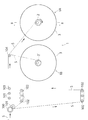
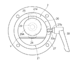
図1に示すように、用紙巻取り装置1は、2つの用紙巻取り機構1A、1Bを備えている。各巻取り機構1A、1Bは、台紙Sを巻き取るための巻取り軸部2、2’をそれぞれ有している。用紙巻取り装置1の上流側(図左側)には、図示していないが、ラベル貼付け装置(ラベラー)が配置されており、用紙巻取り装置1には、ラベル貼付け装置でラベル貼付け処理が施されてラベルが剥離された台紙Sが矢印方向から供給されるようになっている。供給されてきた台紙Sは、ローラ100およびテンションローラ101を経て、下方に配置された複数のローラ102および上方に配置された複数のローラ103に交互に掛け渡された後、各用紙巻取り機構1A、1Bの上方に配置されたローラ104を経ていずれかの用紙巻取り機構1A、1Bに巻き取られる。
As shown in FIG. 1, the
図1においては、台紙Sが用紙巻取り機構1Aに巻き取られる場合を示しており(実線参照)、用紙巻取り機構1Aの巻取り軸部2に所定長さの台紙Sがロール状に巻き取られた後は、ローラ104と用紙巻取り機構1Aの巻取り軸部2との間のスパンで台紙Sが切断され、切断された台紙Sの端部が用紙巻取り機構1Bの巻取り軸部2’に係止されて巻取り軸部2’での巻取りが開始されるとともに(二点鎖線参照)、このとき、用紙巻取り機構1Aにおいては、巻取り軸部2にロール状に巻き取られた台紙Sの取外し作業が行われる。同様にして、用紙巻取り機構1Bの巻取り軸部2’に所定長さの台紙Sがロール状に巻き取られた後は、ローラ104と用紙巻取り機構1Bの巻取り軸部2’との間のスパンで台紙Sが切断され、切断された台紙Sの端部が用紙巻取り機構1Aの巻取り軸部2に係止されて巻取り軸部2での巻取りが開始されるとともに、このとき、用紙巻取り機構1Bにおいては、巻取り軸部2’にロール状に巻き取られた台紙Sの取外し作業が行われる。このようにして、用紙巻取り装置1においては、2つの用紙巻取り機構1A、1Bによる台紙Sの巻取り(つまり巻取り軸2、2’の切替え)を交互に行うことで、台紙Sの巻取りを中断することなく、連続して処理を行えるようになっている。
FIG. 1 shows a case where the mount S is wound up by the
なお、各ローラ102は、図1中の実線に示す下方位置と、同図中の一点鎖線で示す上方位置との間のバッファゾーンを移動可能に設けられており、巻取り軸部2、2’を切り替える際には、各ローラ102をこれら上方位置および下方位置間で移動させることにより、巻取り軸部2、2’の切替えをスムーズに行えるようになっている。
Each
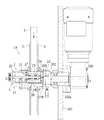
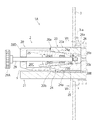
用紙巻取り機構1Aは、図2および図3に示すように、巻取り時の台紙Sの幅方向の一端側および他端側をそれぞれガイドする円板状の一対の側板部材3(31、32)を有している(図1参照)。巻取り軸部2は、各側板部材31、32を挿通して軸方向に延びている。また、用紙巻取り機構1Aは、巻取り軸部2を回転駆動するための減速機付サーボモータ200を有している。サーボモータ200の出力軸200aは、壁パネル201に回転自在に支持されており、その軸端にはフランジ部材202が固定されている。
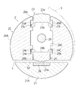
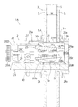
巻取り軸部2は、図2ないし図4に示すように、スリットsを介して半径方向に離隔配置された円筒状の第1の巻取り軸部20および略半円柱状の第2の巻取り軸部21から構成されており、第1の巻取り軸部20の外周面20Aおよび第2の巻取り軸部21の外周面21Aにより、全体として円筒状の外周面を有している。第1、第2の巻取り軸部20、21の基端側の底部20B、21Bは、ベース部材22を介してフランジ部材202に固定されている。
As shown in FIGS. 2 to 4, the take-up
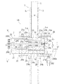
巻取り軸部2のスリットsは、巻取り軸部2の中心軸線O−O’から離れた位置に配置され、巻取り軸部2の外周面に開口するとともに軸方向に延びている。相対的に大形の第1の巻取り軸部20は、外周面20Aの一部に形成されかつ外周面20Aに開口する第1のポケット穴20aと、スリットsに開口する第2のポケット穴20bとを有しており、各ポケット穴20a、20bは第1の巻取り軸部20の内部で連通している。各ポケット穴20a、20bは、第1の巻取り軸部20の軸方向中央部から基端側の底部20Bの手前側まで軸方向に延びている。
The slit s of the winding
第1のポケット穴20aには、第1の内側テーパ部材23が半径方向移動自在に収容され、第2のポケット穴20bには、第2の内側テーパ部材24が半径方向移動自在に収容されており、第1、第2の内側テーパ部材23、24が半径方向に移動することで、第1、第2のポケット穴20a、20bからの各内側テーパ部材23、24の突出量が変化するようになっている。また、第1、第2のポケット穴20a、20bを連通する内部空間20Cには、第1、第2の内側テーパ部材23、24を半径方向に移動させるためのブラケット部材(外側テーパ部材)25が配置されている。
A first
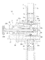
第1の内側テーパ部材23は、第1のポケット穴20aの外側に配置されかつ台紙Sの幅wを越えて軸方向に直線状に延びる(すなわち、台紙Sの幅方向全体にわたって延在する)とともに各側板部材31、32を越えてその外側まで延びる円筒状の外側面23aと、外側面23aに対向して第1のポケット穴20aの内側に配置され、巻取り軸部2の基端側に向かって徐々に小径となるように軸方向にテーパ状に延びる第1のテーパ状内側面23bとを有している。同様に、第2の内側テーパ部材24は、第2のポケット穴20bの外側に配置されかつ台紙Sの幅wを越えて軸方向に直線状に延びる(すなわち、台紙Sの幅方向全体にわたって延在する)円筒状の外側面24aと、外側面24aに対向して第2のポケット穴20bの内側に配置され、巻取り軸部2の基端側に向かって徐々に小径となるように軸方向にテーパ状に延びる第2のテーパ状内側面24bとを有している。
The first
ブラケット部材25は、第1の内側テーパ部材23の第1のテーパ状内側面23bに対応しかつこれに係合し得る第1のテーパ状外側面25aと、これと逆側に配置されるとともに、第2の内側テーパ部材24の第1のテーパ状内側面24bに対応しかつこれに係合し得る第2のテーパ状外側面25bとを有している。なお、ブラケット部材25と異なり、第1、第2の内側テーパ部材23、24は別部材であるため、第1、第2のテーパ状内側面23b、24bは、厳密な意味でのテーパ面ではないが、ブラケット部材25の第1、第2のテーパ状外側面25a、25bにそれぞれ対応しつつ軸方向に対して傾斜して配設されているため、本明細書中では、これらも併せてテーパ面と呼称することにした。
The
第1の内側テーパ部材23の外側面23aを含む上側部分は、図3に示すように、各側板部材31、32に内周側にそれぞれ形成された係合溝31a、32aにそれぞれ係合しており、各係合溝31a、32aは、第1の内側テーパ部材23によりキー結合されるキー溝として機能している。この場合には、各側板部材31、32を巻取り軸部2に連結するためのキー等の軸締結部材を別途必要としないので、構造を簡略化できる。各側板部材31、32の中央には、両端が開口する筒状部材26、27がそれぞれ取り付けられており、これらの筒状部材26、27の内周側にも、第1の内側テーパ部材23によりキー結合されるキー溝として機能する係合溝26a、27aがそれぞれ形成されている。また、スリットs内において、第2の内側テーパ部材24と対向する第2の巻取り軸部21の部位には、たとえばラバー製のプレート部材28が埋設されている。
The upper portion including an
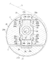
第1の内側テーパ部材23の第1のテーパ状内側面23bの左右端部には、図4に示すように、ブラケット部材25の側に向かって半径方向内方に延びかつ左右側方に張り出す左右一対の張出部23cが設けられている。ブラケット部材25の第1のテーパ状外側面25aを含む外側部分は、第1の内側テーパ部材23の第1のテーパ状内側面23bおよび各張出部23cで限定される凹部内に収容されている。また、第1の巻取り軸部20の第1のポケット穴20aには、第1の内側テーパ部材23の各張出部23cを受け入れる左右一対の凹部20dが形成されている。第1の内側テーパ部材23の半径方向移動時には、第1の内側テーパ部材23の各張出部23cが各凹部20dの各端面20d1、20d2の間を移動する。
As shown in FIG. 4, the left and right ends of the first tapered
同様に、第2の内側テーパ部材24の第2のテーパ状内側面24bの左右端部には、ブラケット部材25の側に向かって半径方向内方に延びかつ左右側方に張り出す左右一対の張出部24cが設けられている。ブラケット部材25の第2のテーパ状外側面25bを含む外側部分は、第2の内側テーパ部材24の第2のテーパ状内側面24bおよび各張出部24cで限定される凹部内に収容されている。また、第1の巻取り軸部20の第2のポケット穴20bには、第2の内側テーパ部材24の各張出部24cを受け入れる左右一対の凹部20eが形成されている。第2の内側テーパ部材24の半径方向移動時には、第2の内側テーパ部材24の各張出部24cが各凹部20eの各端面20e1、20e2の間を移動する。
Similarly, at the left and right ends of the second tapered
円筒状の第1の巻取り軸部20の内部空間20Cには、第1の巻取り軸部20の軸芯O1−O1’を通って軸方向に延びる操作軸29が配設されている。操作軸29は、第1の巻取り軸部20の端部20Dを挿通して軸方向に延びており、手前側端には操作つまみ29Aが設けられ、先端には雄ネジ部29aが形成されている。雄ネジ部29aは、第1の巻取り軸部20の底部20Bに形成された雌ネジ部20cに螺合している。操作軸29は、ブラケット部材25を軸方向に挿通するとともに、ブラケット部材25に回転自在に支持されかつ軸方向移動不能に固定されている。
In the
この構成により、操作者が操作つまみ29Aを介して操作軸29を回転操作すると、操作軸29の雄ネジ部29aが第1の巻取り軸部20の底部20Bの雌ネジ部20cに対して進入または後退することにより、操作軸29およびブラケット部材25が軸方向に前進または後退するようになっており、ブラケット部材25が軸方向に移動することで、第1、第2の内側テーパ部材23、24が半径方向に移動する。
With this configuration, when the operator rotates the operating
筒状部材27の外周面には、図5に示すように、レバー30が設けられており、レバー30の軸部には雄ネジ部30aが形成されている。一方、筒状部材27には、これを半径方向に挿通する貫通孔が形成されており、当該貫通孔には、レバー軸部の雄ネジ部30aが螺合する雌ネジ部27bが形成されている。レバー30を回転させてレバー軸部の雄ネジ部30aの先端を第1の巻取り軸部20の外周面に圧接させることで、レバー軸部の雄ネジ部30aは、筒状部材27を第1の巻取り軸部20に固定する止めネジとして機能している。
As shown in FIG. 5, a
次に、上述した用紙巻取り機構1Aによる台紙巻取り時の作業手順について、図6ないし図9を用いて説明する。
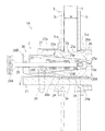
まず、図6に示すように、操作つまみ29Aで操作軸29を回転操作するとともに軸方向に移動させて操作軸29の雄ネジ部29aを第1の巻取り軸部20の底部20Bの雌ネジ部20cから外して後退させることにより、操作軸29およびブラケット部材25を軸方向に後退させるとともに、用紙巻取り機構1Aから筒状部材27および側板部材32を取り外す。
Next, a work procedure at the time of winding the backing paper by the above-described
First, as shown in FIG. 6, the operating
このとき、図7に示すように、第1の内側テーパ部材23が半径方向内方に移動されて、第1の内側テーパ部材23の第1のポケット穴20aからの突出量が小さくなるとともに、第2の内側テーパ部材24が半径方向内方に移動されて、第2の内側テーパ部材24の第2のポケット穴20bからの突出量が小さくなり、スリットs内において、第2の内側テーパ部材24の外側面24aと第2の巻取り軸部21側のプレート部材28との間に隙間が形成される。この状態から、台紙Sの始端Saを当該隙間に挿入する。
At this time, as shown in FIG. 7, the first
次に、図8に示すように、側板部材32および筒状部材27を組み込む。このとき、側板部材32の内周側の係合溝32aおよび筒状部材27の係合溝27aを第1の内側テーパ部材23の外側面23aを含む外側部分に係合させて、筒状部材27を側板部材32に固定するとともに、レバー30を操作して、筒状部材27を第1の巻取り軸部20の外周面に固定する。側板部材32の組込時には、側板部材31との間隔は、台紙Sの幅wよりも若干大きな寸法に設定される。
Next, as shown in FIG. 8, incorporating a
また、図9に示すように、操作つまみ29Aで操作軸29を軸方向に前進させ、先端の雄ネジ部29aを第1の巻取り軸部20の底部20Bの雌ネジ部20cに挿入させるとともに、操作つまみ29Aで操作軸29を回転操作し、雄ネジ部29aを雌ネジ部20cに螺合させてさらに前進させることにより、操作軸29とともにブラケット部材25を軸方向に前進させる。
Further, as shown in FIG. 9, the operating
すると、ブラケット部材25の第1のテーパ状外側面25aが第1の内側テーパ部材23の第1のテーパ状内側面23bと係合して第1の内側テーパ部材23を半径方向外方に移動させることにより、第1の内側テーパ部材23の外側面23aの第1のポケット穴20aからの突出量が大きくなる(図4参照)。それと同時に、ブラケット部材25の第2のテーパ状外側面25bが第2の内側テーパ部材24の第2のテーパ状内側面24bと係合して第2の内側テーパ部材24を半径方向外方に移動させることにより、第2の内側テーパ部材24の外側面24aの第2のポケット穴20bからの突出量が大きくなる(同図参照)。これにより、巻取り軸部2とは別個に設けられた部材を必要とすることなく、台紙Sの始端Saを第2の内側テーパ部材24の外側面24aと第2の巻取り軸部21側のプレート部材28との間で簡単かつ確実に把持することができる(同図参照)。
Then, the first tapered
この状態から、減速機付きサーボモータ200(図2)を駆動して出力軸200aを回転させると、巻取り軸部2とともに各側板部材31、32および各筒状部材26,27が回転し、これにより、第1の巻取り軸部20の外周面20A、第2の巻取り軸部21の外周面21Aおよび第1の内側テーパ部材23の外側面23aの周りに台紙Sが巻き付けられる(図4参照)。
From this state, when the
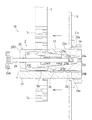
次に、用紙巻取り機構1Aに巻き取られた台紙Sを巻取り軸部2から取り外す際の作業手順について、図10ないし図12を用いて説明する。
図10は、用紙巻取り機構1Aに台紙Sが所定長さ分だけロール状に巻き取られた状態を示しており、図中、台紙Sのロール体が参照符号SRで表されている。
Next, a work procedure for removing the mount S wound on the
FIG. 10 shows a state in which the backing sheet S is wound in a roll shape by a predetermined length on the
この状態から、操作つまみ29Aで操作軸29を回転操作するとともに軸方向に移動させて操作軸29の雄ネジ部29aを第1の巻取り軸部20の底部20Bの雌ネジ部20cから外して後退させることにより、操作軸29およびブラケット部材25を軸方向に後退させるとともに(図11参照)、用紙巻取り機構1Aから筒状部材27および側板部材32を取り外す。
From this state, the operating
操作軸29およびブラケット部材25が軸方向に後退することにより、ブラケット部材25の第1のテーパ状外側面25aと第1の内側テーパ部材23の第1のテーパ状内側面23bとの間に隙間が形成されようとするが、このとき、第1の内側テーパ部材23の外側面23aに作用するロール体SRからの巻付圧により、または、操作者が筒状部材27を側板部材32から取り外した状態で第1の内側テーパ部材23の外側面23aを半径方向内方に押し込むことにより、上記隙間は解消する。その結果、図11に示すように、第1の内側テーパ部材23の第1のポケット穴20aからの突出量が小さくなって、巻取り軸部2の外周面および第1の内側テーパ部材23の外側面23aによる巻き取り径を台紙Sの幅方向全体にわたって縮径できる。
When the
また、操作軸29およびブラケット部材25が軸方向に後退することにより、ブラケット部材25の第2のテーパ状外側面25bから第2の内側テーパ部材24の第2のテーパ状内側面24bに対して作用していた押付圧がなくなるので、台紙Sの始端Saに作用していた、第2の内側テーパ部材24の外側面24aと第2の巻取り軸部21側のプレート部材28との間の把持圧もなくなる。
Further, as the
したがって、図12に示すように、ロール体SRを含む台紙S全体を手前側(図示矢印方向)に移動させることで、始端Saが巻取り軸部2に把持されかつ巻取り軸部2の外周面および第1の内側テーパ部材23の外側面23aに巻き取られていた台紙Sを巻取り軸部2から簡単に取り外すことができる。
Therefore, as shown in FIG. 12, by moving the entire mount S including the roll body S R to the front side (the direction of the arrow in the drawing), the start end Sa is gripped by the winding
しかも、ブラケット部材25が第1の内側テーパ部材23の第1のテーパ状内側面23bに対応する第1のテーパ状外側面25aを有していることで、ブラケット部材25の第1のテーパ状外側面23bおよび第1の内側テーパ部材23の第1のテーパ状内側面23bがそれぞれくさび面として面接触するので、ブラケット部材25の軸方向移動および第1の内側テーパ部材23の半径方向移動を比較的小さな力で行うことができ、これにより、巻取り軸部2からの台紙Sの取外しを速やかに行うことができる。
Moreover, since the
さらに、第1の巻取り軸部2の底部20Bの雌ネジ部20cに螺合する操作軸29先端の雄ネジ部29aによる推力を利用して操作軸29およびブラケット部材25が軸方向に移動するので、ブラケット部材25の軸方向移動および第1の内側テーパ部材23の半径方向移動をより小さな力で行うことができる。
Further, the operating
また、ブラケット部材25の軸方向移動により、第1の内側テーパ部材23のみならず第2の内側テーパ部材24についても半径方向に移動させることができるので、第1の内側テーパ部材23の第1のポケット穴20aからの突出量の調整のみならず、第2の内側テーパ部材24による用紙Sの始端Saの把持および解除についても、操作軸29の回転操作のみで簡単かつ確実に行えるようになり、これにより、効率的に用紙の巻取りおよび取外しの処理を行うことができるようになる。
Further, by moving the
以上、本発明に好適な実施例について説明したが、本発明の適用はこれに限定されるものではなく、本発明には種々の変形例が含まれる。以下に変形例のいくつかの例を挙げておく。 Although the preferred embodiment of the present invention has been described above, the application of the present invention is not limited to this, and the present invention includes various modifications. Some examples of modifications will be given below.
<第1の変形例>
前記実施例では、好ましい態様として、用紙巻取り装置1が2つの用紙巻取り機構1A、1Bから構成された例を示したが、本発明の適用はこれに限定されない。用紙巻取り装置1は、3つ以上の用紙巻取り機構から構成されていてもよいし、また、単一の用紙巻取り機構から構成されていてもよい。
<First Modification>
In the above-described embodiment, as a preferred mode, the
<第2の変形例>
前記実施例では、好ましい態様として、巻取り軸部2が第1、第2の巻取り軸部20、21から構成された例を示したが、巻取り軸部2は、概略円柱状の単一の巻取り軸部から構成されていてもよい。その場合、巻取り軸部の外周面に台紙Sの始端を保持するための保持部を別途設ける必要がある。
<Second Modification>
In the embodiment described above, as a preferred mode, the winding
<第3の変形例>
前記実施例では、第1の内側テーパ部材23の各張出部23cと、第1のポケット穴20aの各凹部20dの各端面20d1、20d2との間に単に空所のみが形成された例を示したが(図4参照)、本発明の適用はこれに限定されない。たとえば、第1の内側テーパ部材23の各張出部23cと、第1のポケット穴20aの各凹部20dの端面20d1との間に圧縮バネを配設するようにしてもよい。この場合、操作軸29およびブラケット部材25の後退時には、第1の内側テーパ部材23が圧縮バネの反発力により半径方向内方に容易に移動できるようになる。
<Third Modification>
In the above-described embodiment, only a void is formed between each overhanging
同様に、前記実施例では、第2の内側テーパ部材24の各張出部24cと、第2のポケット穴20bの各凹部20eの各端面20e1、20e2との間に単に空所のみが形成された例を示したが(図4参照)、本発明の適用はこれに限定されない。たとえば、第2の内側テーパ部材24の各張出部24cと、第2のポケット穴20bの各凹部20eの端面20e2との間に圧縮バネを配設するようにしてもよい。この場合、操作軸29およびブラケット部材25の後退時には、第2の内側テーパ部材24が圧縮バネの反発力により半径方向内方に容易に移動できるようになる。
Similarly, in the above-described embodiment, only a vacant space is formed between each overhanging
<第4の変形例>
前記実施例では、長尺の帯状の用紙として、裏面に粘着面を有するラベルが台紙に仮着されたラベル台紙からラベルが剥離された台紙を例にとって説明したが、本発明の適用はこれに限定されるものではなく、その他の連続用紙でもよく、またフィルム用紙であってもよい。
<Fourth Modification>
In the embodiment, as the long strip-shaped paper, the label having the adhesive surface on the back side is explained as an example of the mount which is peeled off from the label mount which is temporarily attached to the mount, but the application of the present invention is not limited to this. It is not limited, and may be other continuous paper or film paper.
<その他の変形例>
上述した実施例および各変形例はあらゆる点で本発明の単なる例示としてのみみなされるべきものであって、限定的なものではない。本発明が関連する分野の当業者は、本明細書中に明示の記載はなくても、上述の教示内容を考慮するとき、本発明の精神および本質的な特徴部分から外れることなく、本発明の原理を採用する種々の変形例やその他の実施例を構築し得る。
<Other modifications>
The embodiments and modifications described above are to be considered in all respects as merely exemplifications of the invention and are not limiting. Those skilled in the art to which the present invention pertains, even if not explicitly stated herein, when considering the above teachings without departing from the spirit and essential characteristics of the invention. Various modifications and other embodiments adopting the above principle can be constructed.
以上のように、本発明は、長尺の帯状の用紙を巻き取るための用紙巻取り機構に有用である。 INDUSTRIAL APPLICABILITY As described above, the present invention is useful for a paper winding mechanism for winding a long strip of paper.
1: 用紙巻取り装置
1A: 用紙巻取り機構
2 : 巻取り軸部
20: 第1の巻取り軸部
20A: 外周面
20a: 第1のポケット穴
20b: 第2のポケット穴
20B: 底部(端部)
20c: 雌ネジ部(雌ネジ孔)
21: 第2の巻取り軸部
21A: 外周面
23: 第1の内側テーパ部材
23a: 外側面
23b: 第1のテーパ状内側面
24: 第2の内側テーパ部材
24a: 外側面
24b: 第2のテーパ状内側面
25: ブラケット部材(外側テーパ部材)
25a: 第1のテーパ状外側面
25b: 第2のテーパ状外側面
29 : 操作軸
29a: 雄ネジ部
3、31、32: 側板部材
31a、32a: 係合溝(キー溝)
s: スリット
S: 台紙(用紙)
Sa: 始端
w: 幅
1: Paper take-up
2: Winding shaft
20: 1st winding
20c: Female screw part (female screw hole)
21: Second winding
23: 1st inner
24: 2nd inner
25: Bracket member (outer taper member)
25a: first tapered
29:
3,3 1, 3 2:
s: slit
S: Mount (paper)
Sa: Starting point w: Width
Claims (5)
用紙が巻き付けられる外周面を有し、前記外周面の一部にポケット穴が形成された巻取り軸部と、
前記ポケット穴に収容されるとともに、前記ポケット穴の外側に配置されかつ用紙の幅方向全体にわたって延在する外側面と、前記ポケット穴の内側に配置されかつ軸方向にテーパ状に延びるテーパ状内側面とを有し、前記ポケット穴からの前記外側面の突出量が変化するように前記ポケット穴内で半径方向に移動自在な内側テーパ部材と、
前記内側テーパ部材の前記テーパ状内側面に対応しかつ係合し得るテーパ状外側面を有し、前記内側テーパ部材を半径方向に移動させるように軸方向に移動自在な外側テーパ部材とを備え、
前記巻取り軸部が、前記外周面に開口しかつ軸方向に延びるスリットを介して離隔配置された第1、第2の巻取り軸部から構成されるとともに、前記第1の巻取り軸部が、前記外周面の一部に形成された第1のポケット穴と、前記スリットに開口する第2のポケット穴とを有し、前記第1、第2のポケット穴にそれぞれ第1、第2の内側テーパ部材が収容されており、前記外側テーパ部材が、前記第1、第2の内側テーパ部材の第1、第2のテーパ状内側面にそれぞれ対応しかつ係合し得る第1、第2のテーパ状外側面を有しており、用紙の始端が前記スリット内において前記第2の内側テーパ部材の前記外側面と前記第2の巻取り軸部との間で把持されるようになっている、
ことを特徴とする用紙巻取り機構。 A paper winding mechanism for winding a long strip of paper,
A winding shaft portion having an outer peripheral surface around which the paper is wound, and pocket holes formed in a part of the outer peripheral surface,
An outer side surface that is accommodated in the pocket hole and that is disposed outside the pocket hole and extends over the entire width direction of the paper; and a tapered shape that is disposed inside the pocket hole and extends in a taper direction in the axial direction. An inner taper member having a side surface and movable in the radial direction in the pocket hole so that the amount of protrusion of the outer surface from the pocket hole changes.
The has a tapered outer surface to the tapered inner surface of the inner tapered member may engage corresponding vital engagement, and a movable outer tapered member in the axial direction to move the inner tapered member in the radial direction ,
The winding shaft portion is composed of first and second winding shaft portions which are open to the outer peripheral surface and are spaced apart from each other through a slit extending in the axial direction, and the first winding shaft portion. Has a first pocket hole formed in a part of the outer peripheral surface and a second pocket hole opening to the slit, and the first and second pocket holes respectively have a first pocket and a second pocket hole. Inner taper members are housed, the outer taper members corresponding to and engageable with the first and second tapered inner surfaces of the first and second inner taper members, respectively. 2 has a tapered outer surface, and the start end of the sheet is grasped in the slit between the outer surface of the second inner tapered member and the second winding shaft portion. ing,
A paper winding mechanism characterized in that
前記外側テーパ部材を軸方向に挿通するとともに前記外側テーパ部材に回転自在に支持されかつ軸方向移動不能に固定された操作軸をさらに備え、前記操作軸の先端に形成された雄ネジ部が前記巻取り軸部の端部に形成された雌ネジ部に螺合している、
ことを特徴とする用紙巻取り機構。 In claim 1,
The external taper member is further inserted in the axial direction and further provided with an operation shaft rotatably supported by the outer taper member and fixed so as not to move in the axial direction, and a male screw portion formed at a tip end of the operation shaft is provided. It is screwed into the female screw part formed at the end of the winding shaft.
A paper winding mechanism characterized in that
前記巻取り軸部には、巻取り時の用紙の幅方向の一端側および他端側をそれぞれガイドする一対の側板部材が設けられており、前記各側板部材の内周側には、前記内側テーパ部材によりキー結合されるキー溝が形成されている、
ことを特徴とする用紙巻取り機構。 In claim 1,
The winding shaft portion is provided with a pair of side plate members that respectively guide one end side and the other end side in the width direction of the paper at the time of winding, and the inner side is provided on the inner peripheral side of each side plate member. A key groove is formed which is keyed by a taper member,
A paper winding mechanism characterized in that
前記内側テーパ部材が前記各側板部材を越えてその外側まで延びている、
ことを特徴とする用紙巻取り機構。 In claim 3,
The inner taper member extends beyond the side plate members to the outside thereof,
A paper winding mechanism characterized in that
当該用紙巻取り機構が、ラベル台紙貼付け装置におけるラベル剥離後の台紙を巻き取るためのものである、
ことを特徴とする用紙巻取り機構。 In claim 1,
The paper take-up mechanism is for taking up the mount after the label is peeled off in the label mount attaching device,
A paper winding mechanism characterized in that
Priority Applications (1)
| Application Number | Priority Date | Filing Date | Title |
|---|---|---|---|
| JP2016202301A JP6713402B2 (en) | 2016-10-14 | 2016-10-14 | Paper take-up mechanism |
Applications Claiming Priority (1)
| Application Number | Priority Date | Filing Date | Title |
|---|---|---|---|
| JP2016202301A JP6713402B2 (en) | 2016-10-14 | 2016-10-14 | Paper take-up mechanism |
Publications (2)
| Publication Number | Publication Date |
|---|---|
| JP2018062418A JP2018062418A (en) | 2018-04-19 |
| JP6713402B2 true JP6713402B2 (en) | 2020-06-24 |
Family
ID=61967477
Family Applications (1)
| Application Number | Title | Priority Date | Filing Date |
|---|---|---|---|
| JP2016202301A Active JP6713402B2 (en) | 2016-10-14 | 2016-10-14 | Paper take-up mechanism |
Country Status (1)
| Country | Link |
|---|---|
| JP (1) | JP6713402B2 (en) |
Families Citing this family (1)
| Publication number | Priority date | Publication date | Assignee | Title |
|---|---|---|---|---|
| JP7006559B2 (en) | 2018-10-04 | 2022-01-24 | トヨタ車体株式会社 | Seal sticker for hole closing seal |
Family Cites Families (8)
| Publication number | Priority date | Publication date | Assignee | Title |
|---|---|---|---|---|
| JPS60167843A (en) * | 1984-02-09 | 1985-08-31 | Kurashiki Kikai Kk | Scrap winder |
| JPH079855U (en) * | 1993-07-22 | 1995-02-10 | ニューロング株式会社 | Winding device |
| JP2002184636A (en) * | 2000-12-14 | 2002-06-28 | Aichi Electric Co Ltd | Winding device for wound core |
| JP4889515B2 (en) * | 2007-01-30 | 2012-03-07 | サトーホールディングス株式会社 | Ribbon winding reel |
| JP4922999B2 (en) * | 2008-05-19 | 2012-04-25 | 東芝テック株式会社 | Printer |
| JP5471424B2 (en) * | 2009-12-24 | 2014-04-16 | 株式会社寺岡精工 | Belt winding mechanism |
| JP5834837B2 (en) * | 2011-11-30 | 2015-12-24 | セイコーエプソン株式会社 | Core tube holding device and image recording device |
| JP6472077B2 (en) * | 2015-03-23 | 2019-02-20 | グラフテック株式会社 | Roll paper width regulating rod and printing system having the same |
-
2016
- 2016-10-14 JP JP2016202301A patent/JP6713402B2/en active Active
Also Published As
| Publication number | Publication date |
|---|---|
| JP2018062418A (en) | 2018-04-19 |
Similar Documents
| Publication | Publication Date | Title |
|---|---|---|
| JP6713402B2 (en) | Paper take-up mechanism | |
| JP5164582B2 (en) | Coating film transfer tool | |
| US7128291B1 (en) | Spool having an extractor bar | |
| JP6480069B1 (en) | Winding device for sheet-like products on a winding tube | |
| JP5272147B2 (en) | Paper supply device | |
| JP2597864Y2 (en) | Winding mechanism for band | |
| CN105683048B (en) | Change the equipment of the paper bowl of labeller and change the correlation method of paper bowl | |
| JP4885216B2 (en) | Expandable reel mandrel | |
| WO2010041351A1 (en) | Roller device | |
| JP2010083086A (en) | Tape delivery apparatus | |
| JPS59118644A (en) | Method and device for hoisting continuous advancing web | |
| JP2008207925A (en) | Support device and labelling device | |
| JP4640350B2 (en) | Belt winding device | |
| JP4730960B2 (en) | Double-sided tape stamper | |
| JP2004299862A (en) | Ribbon winding device | |
| JP2005320159A (en) | Separation device for sheets of recording media | |
| JP2008195500A (en) | Winding shaft | |
| JP4582878B2 (en) | Film roll core device | |
| FR2953447A1 (en) | PRINTING GROUP OF PRINTING MACHINE AND METHOD OF CHANGING PRINTING PLATES | |
| JP2008037511A (en) | Web winding machine | |
| JP6250426B2 (en) | Label printer | |
| JP2803985B2 (en) | Rotary printing press | |
| JP2004231399A (en) | Manufacturing method of coreless sheet roll, and core and jig used in the method | |
| JP2002019079A (en) | Blanket cylinder | |
| JP6218527B2 (en) | Label peeling machine |
Legal Events
| Date | Code | Title | Description |
|---|---|---|---|
| A621 | Written request for application examination |
Free format text: JAPANESE INTERMEDIATE CODE: A621 Effective date: 20190416 |
|
| A977 | Report on retrieval |
Free format text: JAPANESE INTERMEDIATE CODE: A971007 Effective date: 20200210 |
|
| A131 | Notification of reasons for refusal |
Free format text: JAPANESE INTERMEDIATE CODE: A131 Effective date: 20200304 |
|
| A521 | Request for written amendment filed |
Free format text: JAPANESE INTERMEDIATE CODE: A523 Effective date: 20200331 |
|
| TRDD | Decision of grant or rejection written | ||
| A01 | Written decision to grant a patent or to grant a registration (utility model) |
Free format text: JAPANESE INTERMEDIATE CODE: A01 Effective date: 20200601 |
|
| A61 | First payment of annual fees (during grant procedure) |
Free format text: JAPANESE INTERMEDIATE CODE: A61 Effective date: 20200603 |
|
| R150 | Certificate of patent or registration of utility model |
Ref document number: 6713402 Country of ref document: JP Free format text: JAPANESE INTERMEDIATE CODE: R150 |
|
| R250 | Receipt of annual fees |
Free format text: JAPANESE INTERMEDIATE CODE: R250 |
|
| R250 | Receipt of annual fees |
Free format text: JAPANESE INTERMEDIATE CODE: R250 |