JP6711684B2 - One-way clutch, one-way clutch device, and pulley device - Google Patents
One-way clutch, one-way clutch device, and pulley device Download PDFInfo
- Publication number
- JP6711684B2 JP6711684B2 JP2016092787A JP2016092787A JP6711684B2 JP 6711684 B2 JP6711684 B2 JP 6711684B2 JP 2016092787 A JP2016092787 A JP 2016092787A JP 2016092787 A JP2016092787 A JP 2016092787A JP 6711684 B2 JP6711684 B2 JP 6711684B2
- Authority
- JP
- Japan
- Prior art keywords
- sprag
- way clutch
- rotation
- plate
- plates
- Prior art date
- Legal status (The legal status is an assumption and is not a legal conclusion. Google has not performed a legal analysis and makes no representation as to the accuracy of the status listed.)
- Active
Links
Images


Landscapes
- Pulleys (AREA)
Description
本発明は、駆動側部から従動側部への一方向の正駆動回転を伝達し、逆方向の逆駆動回転を空転する一方向クラッチ及び一方向クラッチ装置並びにそれを用いたプーリ装置に関する。
BACKGROUND OF THE
従来、自動車のエンジンのクランクシャフトの回転を各種補機類、例えばオルタネータに伝達するプーリ装置にあって、一方向クラッチを介在したものが知られている(特許文献1参照)。該一方向クラッチは、クランクシャフトからベルトを介して伝達するプーリの一方向回転を上記オルタネータのロータ軸に伝達し、エンジンの回転低下によるロータ軸からエンジン方向への送駆動回転を空転する。 2. Description of the Related Art Conventionally, there is known a pulley device that transmits the rotation of a crankshaft of an automobile engine to various auxiliary devices such as an alternator, in which a one-way clutch is interposed (see Patent Document 1). The one-way clutch transmits the one-way rotation of the pulley transmitted from the crankshaft via the belt to the rotor shaft of the alternator, and idles the feed drive rotation from the rotor shaft to the engine due to the decrease in the engine rotation.
上記一方向クラッチを内蔵したプーリ装置を採用することにより、慣性の大きなオルタネータ等への駆動にあって、エンジンのトルク変動により繰返し生じるベルトの張力変化を低減し、また減速状態から加速したときのベルトスリップの発生を低減して、ベルト寿命の向上及びベルトスリップ音の抑制等が図られる。 By adopting the pulley device with the built-in one-way clutch, it is possible to reduce the belt tension change that is repeatedly caused by the torque fluctuation of the engine when driving to an alternator with a large inertia, and when accelerating from the deceleration state. The occurrence of belt slip is reduced, the belt life is improved, and the belt slip noise is suppressed.
近時、ディーゼルエンジン、並びにダウンサイジングしたガソリンエンジンは、トルク変動が大きいため、上記一方向クラッチを内蔵したプーリ装置の採用が期待されており、このため一方向クラッチには、高いトルク容量が求められており、またオルタネータの高回転化に伴い、高いトルク容量を維持しつつ小径化等の小型化が求められている。 Recently, since diesel engines and downsized gasoline engines have large torque fluctuations, it is expected that a pulley device incorporating the above-mentioned one-way clutch will be adopted. Therefore, a high torque capacity is required for the one-way clutch. In addition, as the alternator has a higher rotation speed, a smaller size such as a smaller diameter is required while maintaining a high torque capacity.
一般に、一方向クラッチは、内輪と外輪との間に介在するスプラグ(係合子)を有しており、周方向に等間隔で多数配置されたこれらスプラグは、一方向に傾くように付勢されて内輪及び外輪との間に係合して回転を伝達し、上記付勢力に抗してスプラグを傾動することにより空転する。 Generally, a one-way clutch has sprags (engagers) interposed between an inner ring and an outer ring, and a large number of these sprags arranged at equal intervals in the circumferential direction are biased so as to be inclined in one direction. The inner ring and the outer ring are engaged with each other to transmit the rotation, and the sprag is tilted against the urging force to rotate idly.
従来、スプラグは、円弧形状の外周面からなる微妙な形状からなり、軸方向に所定長さを有するブロック状の一体物からなる(特許文献1参照)。該スプラグは、一般に、引抜き加工により成形され、該引抜き加工後に熱処理されるため、ひずみは避けられない。また、上記スプラグが接触する外輪の内周面及び内輪の外周面は、研削加工により仕上げられるが、コスト面及びスプラグ精度との整合等により精度向上には限度があり、外輪内周面及び内輪外周面の空間の径寸法が軸方向においてばらつくことは避けられない。 Conventionally, a sprag has a delicate shape including an arcuate outer peripheral surface and is a block-shaped integral body having a predetermined length in the axial direction (see Patent Document 1). Since the sprag is generally formed by drawing and heat-treated after the drawing, strain is unavoidable. Further, the inner peripheral surface of the outer ring and the outer peripheral surface of the inner ring, which come into contact with the sprags, are finished by grinding, but there is a limit to improvement in accuracy due to cost and matching with sprag accuracy, and the inner peripheral surface of the outer ring and the inner ring are limited. It is unavoidable that the diameter of the space on the outer peripheral surface varies in the axial direction.
これらにより、スプラグは、外輪内周面及び内輪外周面に対して線接触することは困難となり、スプラグの幅方向(軸方向)の接触領域が減少する。その結果、スプラグがトルク伝達する際に外輪内周面及び内輪外周面に対して滑りやすくなってしまい、トルク容量を低減してしまう。このため、近時のトルク変動の大きいエンジンに対して、一方向クラッチのトルク容量を確保することを困難にしている。 As a result, it becomes difficult for the sprag to make line contact with the inner peripheral surface of the outer ring and the outer peripheral surface of the inner ring, and the contact area in the width direction (axial direction) of the sprag is reduced. As a result, when the sprag transmits torque, it becomes slippery on the inner peripheral surface of the outer ring and the outer peripheral surface of the inner ring, and the torque capacity is reduced. For this reason, it is difficult to secure the torque capacity of the one-way clutch for an engine that has a large torque fluctuation recently.
そこで、本発明は、不可避な加工ひずみや寸法のばらつきが存在しても、一方向クラッチのトルク容量を確保することを可能とし、もって上述した課題を解決した一方向クラッチ及び一方向クラッチ装置並びにそれを内蔵したプーリ装置を提供することを目的とする。 Therefore, the present invention makes it possible to secure the torque capacity of the one-way clutch even if there are unavoidable processing strains and dimensional variations, and thus a one-way clutch and a one-way clutch device that solve the above-mentioned problems. It is an object of the present invention to provide a pulley device incorporating it.
本発明は、駆動側の回転が従動側の回転より相対的に速い一方向回転を伝達し、前記従動側の回転が前記駆動側の回転より相対的に速い一方向回転を空転する一方向クラッチ(6)であって、
所定板厚のプレート部材であるスプラグプレート(9a…)を所定多数枚積層して構成されたスプラグ(9)と、
前記スプラグ(9)を構成する多数のスプラグプレート(9a)を、それぞれ傾動自在にかつ1列状に配置し、該1列状のスプラグプレートを周方向に多数保持する保持手段(10,10,15)と、を備えてなる、
ことを特徴とする一方向クラッチである。
The present invention relates to a one-way clutch in which a drive-side rotation transmits a one-way rotation that is relatively faster than a driven-side rotation, and the driven-side rotation idles a one-way rotation that is relatively faster than the drive-side rotation. (6),
A sprag (9) constituted by laminating a predetermined number of sprag plates (9a...) As plate members having a predetermined plate thickness;
A plurality of sprag plates (9a) forming the sprag (9) are tiltably arranged in one row, and holding means (10, 10,, 10) for holding a large number of the one row sprag plates in the circumferential direction. 15) and,
It is a one-way clutch characterized in that.
例えば図2,図3を参照して、前記保持手段は、前記1列状のスプラグプレート(9a)を間に保持する1対のエンドプレート(10,10)と、前記スプラグプレート(9a)に形成されたピン孔(11)及び前記エンドプレート(10)に形成された貫通孔(12)に挿通するピン(15)と、を有し、
前記ピン(15)を前記貫通孔(12)に固定して、所定の寸法間隔に前記1対のエンドプレート(10,10)を保持すると共に、前記ピン(15)に前記ピン孔(11)を遊嵌して、前記各スプラグプレート(9a)をそれぞれ傾動自在に支持してなる。
For example, referring to FIGS. 2 and 3, the holding means includes a pair of end plates (10, 10) for holding the one row of sprag plates (9a) therebetween and the sprag plates (9a). A pin hole (11) formed and a pin (15) inserted into a through hole (12) formed in the end plate (10),
The pin (15) is fixed to the through hole (12) to hold the pair of end plates (10, 10) at a predetermined dimensional interval, and the pin (15) has the pin hole (11). Is loosely fitted, and each sprag plate (9a) is tiltably supported.
例えば図3,図4を参照して、前記1対のエンドプレート(10,10)に所定間隔毎にバネ支持体(16)を固定し、
前記各バネ支持体(16)にそれぞれスプラグバネ(17)を取付け、前記各スプラグバネ(17)で前記1列状のスプラグプレート(9a…)を係合姿勢に向けて付勢してなる。
For example, referring to FIGS. 3 and 4, spring support bodies (16) are fixed to the pair of end plates (10, 10) at predetermined intervals,
A sprag spring (17) is attached to each of the spring supports (16), and the sprag plates (9a...) In one row are biased toward the engaging posture by the sprag springs (17).
前記スプラグバネ(17)は、板バネからなり、前記バネ支持体(16)に固定される固定部(17a)と、前記1列状のスプラグプレート(9a…)に当接して付勢する付勢部(17b)と、を有する。 The sprag spring (17) is composed of a leaf spring, and is a biasing member that abuts against the fixing portion (17a) fixed to the spring support body (16) and the one-row-shaped sprag plate (9a... ). And a part (17b).
前記スプラグバネ(17)の前記付勢部先端の当接部(T)は、直線状からなる。 The contact portion (T) at the tip of the biasing portion of the sprag spring (17) has a linear shape.
例えば図4を参照して、前記バネ支持体(16)は、該バネ支持体に隣接する前記1列状のスプラグプレート(9a…)に当接してその空転方向(F)の傾動範囲を規定するストッパ(19)を有する。 For example, referring to FIG. 4, the spring support body (16) abuts the one row of sprag plates (9a...) Adjacent to the spring support body and defines a tilting range in the idling direction (F). It has a stopper (19) to operate.
例えば図4を参照して、内輪(4)と、外輪(5)と、前記内輪及び前記外輪の間に配置された前記一方向クラッチ(6)と、を備え、
前記外輪(5)及び前記内輪(4)の一方から(例えば5)他方(例えば4)に向けての一方向回転である正駆動回転を伝達し、前記他方から一方へ向けての一方向回転である逆駆動回転を空転する、
一方向クラッチ装置(8)にある。
For example, referring to FIG. 4, an inner ring (4), an outer ring (5), and the one-way clutch (6) arranged between the inner ring and the outer ring,
One direction rotation is transmitted from one of the outer ring (5) and the inner ring (4) to one side (for example, 5) toward the other side (for example, 4), which is positive drive rotation, and is transmitted from the other side toward one side. The reverse drive rotation, which is
Located in the one-way clutch device (8).
例えば図1を参照して、ハブ(2)と、
該ハブに1対のベアリング(7,7)により回転自在に支持されたプーリ(3)と、
前記一方向クラッチ装置(8)と、を備え、
前記一方向クラッチ(6)は、前記ハブ(2)に一体の内輪(4)と前記プーリ(3)に一体の外輪(5)との間に配置され、
前記1対のベアリング(7,7)の間で前記外輪(5)と前記内輪(4)との間の前記一方向クラッチ(6)を収納する空間(S)に潤滑剤を封入してなる、
プーリ装置にある。
For example, referring to FIG. 1, a hub (2),
A pulley (3) rotatably supported on the hub by a pair of bearings (7, 7);
And a one-way clutch device (8),
The one-way clutch (6) is arranged between an inner ring (4) integral with the hub (2) and an outer ring (5) integral with the pulley (3),
A lubricant is enclosed in a space (S) for accommodating the one-way clutch (6) between the outer ring (5) and the inner ring (4) between the pair of bearings (7, 7). ,
It is on the pulley device.
前記プーリ(3)は、エンジンからの動力が伝達されるベルトを巻掛ける溝(3a)を有し、
前記ハブ(2)は、オルタネータのロータ軸を連結し得る孔(2a)を有する。
The pulley (3) has a groove (3a) around which a belt to which power from the engine is transmitted is wound,
The hub (2) has a hole (2a) for connecting the rotor shaft of the alternator.
なお、前記カッコ内の符号は、図面と対照するためのものであるが、これにより特許請求の範囲の構成に何ら影響を及ぼすものではない。 The reference numerals in the parentheses are for the purpose of contrasting with the drawings, but they do not affect the structure of the claims.
請求項1及び請求項6に係る本発明によると、各スプラグが所定板厚のプレート部材であるスプラグプレートを所定多数枚積層して構成されるので、外輪内周面及び内輪外周面の径寸法が軸方向においてばらつきがあっても、1列状の各スプラグプレートはそれぞれ傾動して、対応する位置の径のばらつきに応じて係合する。これにより、スプラグの接触領域を増大して、一方向クラッチ又は一方向クラッチ装置の係合時の伝達トルク容量を確保することができる。
According to the present invention according to
また、スプラグプレートを保持する保持手段が、1対のエンドプレート及びピンからなるので、簡単な構成でもって各スプラグプレートを傾動自在にかつ1列状に保持することができる。ピンに対するピン孔の所定遊合関係(遊嵌)及び1対のエンドプレートの所定間隔寸法により、各スプラグプレートは、スキューやチルトが許容限定に規定される範囲で、それぞれ独立して迅速に傾動し得、係合姿勢及び空転姿勢に素速く切換え、かつこれら姿勢に安定して、高い精度で作動する耐久性の高い一方向クラッチを提供することができる。 Further , since the holding means for holding the sprag plate is composed of a pair of end plates and pins, each sprag plate can be tilted and held in one row with a simple structure. Due to the predetermined loose fitting relationship of the pin holes with respect to the pins and the predetermined spacing dimension of the pair of end plates, each sprag plate independently and quickly tilts within a range in which the skew and tilt are defined as allowable limits. Therefore, it is possible to provide a highly durable one-way clutch which can be quickly switched between the engagement posture and the idling posture and which is stable in these postures and operates with high accuracy.
請求項2に係る本発明によると、1対のエンドプレートにバネ支持体を固定し、これらバネ支持体に取付けたスプラグバネにより、1列状のスプラグプレートを付勢するので、堅牢な構造で確実に各スプラグプレートを付勢して、正確な一方向クラッチ作動を行うことができる。 According to the second aspect of the present invention, the spring supports are fixed to the pair of end plates, and the sprag springs attached to the spring supports bias the sprag plates in one row, so that the structure is robust and reliable. Accurate one-way clutch operation can be performed by energizing each sprag plate.
請求項3に係る本発明によると、スプラグバネは、板バネからなり、板バネのスナップフィット等により容易かつ確実にバネ支持体に取付けることができ、簡単な構成にて高い生産性を得ることができる。 According to the third aspect of the present invention, the sprag spring is made of a leaf spring, and can be easily and surely attached to the spring support member by a snap fit of the leaf spring or the like, and high productivity can be obtained with a simple configuration. it can.
請求項4に係る本発明によると、上述した寸法精度のばらつきによりスプラグプレートの空転時の傾動角が異なる際、空転方向への傾動角が大きい側にスプラグバネからの付勢力が大きく作用し、比較的早期にスプラグバネの付勢力が1列状の各スプラグプレートに均等に作用する方向に馴染ませることができる。 According to the fourth aspect of the present invention, when the tilt angle of the sprag plate during idling is different due to the above-described variation in dimensional accuracy, the biasing force from the sprag spring acts largely on the side where the tilt angle in the idling direction is large. The urging force of the sprag springs can be quickly adjusted to the direction in which the sprag plates in one row act uniformly.
請求項5に係る本発明によると、各スプラグプレートは、隣接するバネ支持体のストッパに当接して空転方向の傾動範囲が規定されるので、各スプラグプレートを空転姿勢から係合姿勢に適正なタイミングで切換えて一方向クラッチの作動を安定すると共に、スプラグバネの過度の変形を防止して、一方向クラッチの耐久性を向上することができる。 According to the fifth aspect of the present invention, since each sprag plate abuts on the stopper of the adjacent spring support member to define the tilting range in the idling direction, each sprag plate can be adjusted from the idling posture to the engaging posture. It is possible to switch the operation at a timing to stabilize the operation of the one-way clutch, prevent excessive deformation of the sprag spring, and improve the durability of the one-way clutch.
請求項7に係る本発明によると、上記一方向クラッチをプーリ装置に内蔵し、かつ一方向クラッチ収納空間にグリース等の潤滑剤を封入して、潤滑環境で前記各スプラグプレートを独立して傾動して、安定した一方向クラッチ作動を備えたプーリ装置を得ることができ、かつプーリ装置の小型化を図ることができる。 According to the seventh aspect of the present invention, the one-way clutch is built in the pulley device, and a lubricant such as grease is sealed in the one-way clutch storage space to tilt the sprag plates independently in a lubricating environment. Thus, a pulley device having stable one-way clutch operation can be obtained, and the pulley device can be downsized.
請求項8に係る本発明によると、エンジン出力トルクをベルトを介してオルタネータに伝達するプーリ装置に適用して、一方向クラッチの伝達トルクの増大及び安定作動により、ディーゼルエンジン等のトルク変動の大きなエンジンにも適用可能となり、かつベルト寿命の長期化を図ることができる。
According to the present invention according to
以下、図面に沿って本発明の実施の形態について説明する。図1は、一方向クラッチを内蔵したプーリ装置を示し、プーリ装置1は、エンジンからの回転をベルトを介して補機類、具体的にはオルタネータに伝達する。該プーリ装置1は、内輪を構成するハブ2と、プーリ3の内周面に締り嵌め等により一体に固定されている外輪5と、一方向クラッチ6とを有する。ハブ2は、その中央部にオルタネータのロータ軸をネジ等により一体に固定し得る孔2aを有し、従動部を構成する。プーリ3は、複数のVベルトを巻掛け得る溝3aを有し、ベルトを介してエンジンのクランクシャフトに連動し得、駆動部を構成する。ハブ2の外周面は、段付形状からなり、中央部分の大径部分が上記一方向クラッチ6の内輪4となり、その左右の小径部分と上記プーリ3の内周面における左右端部との間にそれぞれボールベアリング7,7が装着されている。ボールベアリング7,7は、それぞれ軸方向外側にシールが取付けられており、外輪5の内周面5a及び内輪4の外周面4aとの間の一方向クラッチ6を収納する空間Sにグリース等の潤滑剤が充填されており、一方向クラッチ6及びボールベアリング7は潤滑環境にある。上記ボールベアリング7,7は、ハブ2にプーリ3を回転自在に支持してベルト張力によるプーリ3のラジアル荷重を担持する。
Embodiments of the present invention will be described below with reference to the drawings. FIG. 1 shows a pulley device having a built-in one-way clutch. The
一方向クラッチ装置8は、上記ボールベアリング7,7の間に配置され、スリーブ状の外輪5と、ハブ2に形成された内輪4と、外輪5の内周面5aと内輪4の外周面4aとの間に介在する前記一方向クラッチ6と、からなる。一方向クラッチ6は、スプラグ9と、該スプラグ9と上記ボールベアリング7,7との間に配置された1対のエンドプレート10,10と、を有する。スプラグ9は、図2(b)及び図3に示すように、所定板厚のプレート部材からなる多数のスプラグプレート9a,9a…が軸方向に積層されて構成される。各スプラグプレート9aは、打抜き成形後、熱処理され、すべて同じ外郭形状を有し、かつ重心位置にピン孔11が形成されている。なお、スプラグプレート9aは、引抜き加工した素材を所定板厚に切断し、かつピン孔11を形成した後熱処理する等、他の方法により製造してもよい。1個のスプラグ9を構成する1列のスプラグプレート9aの枚数は、本実施の形態にあっては8枚であるが、必要トルク容量に応じて任意の枚数に設定可能である。また、スプラグプレート9aからなるスプラグ9は、外輪5の内周面5a及び内輪4の外周面4aの円環状空間の全周に亘って等間隔に多数個配置されており、本実施の形態にあっては11個であるが、要求されるトルク容量に応じて調整される。
The one-way
前記1対のエンドプレート10,10は、図2に示すように、上記スプラグプレート9aより僅かに薄くかつ前記内輪4及び外輪5に接触しない内径及び外径寸法からなる円環状のプレートからなり、周方向に等間隔に貫通孔12…、及び内周面から切欠かれた係合溝13…が形成されている。前記1対のエンドプレート10,10の間に、前記所定枚数(例えば8枚)の1列状のスプラグプレート9a…が保持され、上記ピン孔11及び貫通孔12にピン15が挿入される。ピン15は、各スプラグプレート9aのピン孔11に対して数十μm小さい遊合関係(遊嵌)にあり、エンドプレート10の貫通孔12に対しては圧入された固定関係にあり、従って1列状の各スプラグプレート9aは、両エンドプレート10,10の間で軸方向寸法が規定されると共に、回転(傾動)自在に支持される。上記1対のエンドプレート10,10及びピン15は、周方向に多数個配置されたスプラグ9の各スプラグプレート9aを、傾動自在にかつ1列状に保持する保持手段を構成する。
As shown in FIG. 2, the pair of
両エンドプレート10,10の間の間隔寸法は、スプラグ9を構成する各スプラグプレート9a列の全体の軸方向長さより数百μm大きく設定されており、各スプラグプレート9aは、隣接するスプラグプレート9a又はエンドプレート10との間に潤滑剤(グリース)が浸入し得る僅かな隙間ができ、かつスプラグプレート9aのスキュー(ピン中心軸を含む周方向面におけるピン15に対する傾き)及びチルト(ピン中心軸を含む径方向面におけるピン15に対する傾き)が許容限定内に規制されるように設定される。ピン15の径とピン孔11の孔径との差も、スプラグプレート9aのスキュー及びチルトが許容限定内に規制されるように設定される。
The distance between the two
前記1対のエンドプレート10,10の各係合溝13には、図3及び図4に示すように、それぞれバネ支持体16が固定される。バネ支持体16は、両側部16a,16a及び底部16bを有する全体で凹字形状からなり、かつ両側部16aの外側面から係合突部16cが突出して形成され、これら係合突部16cが上記エンドプレート10の係合溝13に係合する。各バネ支持体16には、それぞれ板バネからなるスプラグバネ17が装着される。スプラグバネ17は、バネ支持体16の両側部16a,16aの間を延びかつその前端16d及び後端16eを挟むようにスナップフィットする固定部17aと、該固定部の一端(回転方向前端)から延びる付勢部17bとを有し、該付勢部17bの先端Tは、回転方向後側のスプラグプレート9a…の外輪5側の側面に当接する。付勢部17bの軸方向長さ(幅)は、1列状のすべてのスプラグプレート9a…に当接する長さからなり、スプラグバネ17は、1列状のすべてのスプラグプレート9aを後述する係合姿勢方向Eに傾動するように付勢する。また、バネ支持体16の他端(回転方向後端)面は、後端側に隣接するスプラグプレート9aの空転側の回動範囲を規制するように、ストッパ19となっている。
As shown in FIGS. 3 and 4, spring supports 16 are fixed to the
スプラグプレート9aは、図4に示すように、外輪5側に向く断面円弧状の第1カム面20と、内輪4側に向く断面円弧状の第2カム面21とを有し、上記第1カム面20及び第2カム面21は、ピン15(正確にはピン孔11)に対してそれぞれ偏心した中心を有しており、スプラグプレート9aのピン15を中心とした傾きにより外輪内周面5aに対して係合する第1係合面20a及び空転する第1空転面20b、並びに内輪外周面4aに対して係合する第2係合面21a及び空転する第2空転面21bを有する。
As shown in FIG. 4, the
一方向クラッチ装置8は、図5(a)に示すように、駆動側である外輪5の回転速度V1が従動側である内輪4の回転速度V2以上となる正駆動の場合(V1≧V2)、スプラグ9は第1カム面20及び第2カム面21の係合面20a,21aがそれぞれ外輪内周面5a、内輪外周面4aにくさび状に係合する方向Eに傾いた係合姿勢となり、外輪5の回転が内輪4に伝達される。該係合姿勢にあっては、外輪内周面5aと内輪外周面4aとの間の空間寸法hより、スプラグ9の上記内周面5a及び外周面4aの接触点での高さHが等しいか又は大きい。
As shown in FIG. 5A, the one-way
図5(b)に示すように、従動側である内輪4の回転速度V2が駆動側である外輪5の回転速度より大きい逆駆動の場合(V1<V2)、スプラグ9は、上記回転速度差(V2−V1)により、スプラグバネ17の付勢に抗してピン15を中心として、空転方向Fに傾く。この状態では、第1空転面20bが外輪内周面5aに遠心力により押し付けられ、内輪外周面4aに第2空転面21bが摺動接触する空転姿勢となる。即ち、上記内周面5aと外周面4aとの間の空間の寸法hが、スプラグ9の両周面との接触部の高さHより大きくなり(H<h)、スプラグ9のくさび作用がなくなって、外輪5から内輪4へのトルク伝達は断たれ、内輪4は空転する。なお、図5において、外輪内周面5a及び内輪外周面4aを便宜的に直線で描いているが、実際は円弧面である。
As shown in FIG. 5B, in the case of reverse driving in which the rotation speed V2 of the
なお、上述説明は、外輪5を駆動側、内輪4を従動側として説明したが、回転方向を矢印と逆方向にして、内輪を駆動側とし、外輪を従動側としても同様である。また、例えば内輪4を固定部材に固定し、外輪5の一方向回転を許容し、他方向の回転を停止してもよい。要は、一方向クラッチ(装置)は、駆動側の回転が従動側の回転より相対的に速い一方向回転を伝達し、従動側の回転が駆動側の回転より相対的に速い一方向回転を空転する。停止は、一方向の回転速度が0であり、逆方向回転は、更に遅いマイナス回転速度となる。
In the above description, the
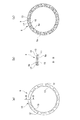
図6(a)は、スプラグ9が1個のブロックからなる従来の技術による一方向クラッチ装置8’を示す。外輪5の内周面5a及び内輪4の外周面4aは、研削により仕上げられるとしても、精度には限界があり、軸方向において径寸法にばらつきがでることは避けられない。また、一方向クラッチ6’のスプラグ9’は、耐摩耗上表面硬度を必要とし、熱処理されるため、ひずみを生じることは避けられない。従って、スプラグ9’が軸方向に長い1個の部材からなる以上、スプラグ9’が上記内周面5a及び外周面4aと接触する領域Cが軸方向の一部分となる。なお、図6にあって、内周面5a及び外周面4aに軸方向において径寸法にばらつきがあるように表記しているが、スプラグ9’の径方向寸法も同様に軸方向においてばらつきがある。
FIG. 6(a) shows a prior art one-way clutch device 8'where the
上記接触領域Cが部分的となって減少するため、スプラグ9’と内周面5a及び外周面4aとの接触に基づく伝達トルク容量は、その分小さくなる。
Since the contact area C is partially reduced, the transmission torque capacity based on the contact of the sprag 9'with the inner
図6(b)は、本発明の実施の形態による一方向クラッチ装置8を示す。各スプラグ9は、多数枚のスプラグプレート9a…が1列状に積層されて構成される。外輪5の内周面5a及び内輪4の外周面4aは、従来の技術と同様に軸方向において径寸法にばらつきがある。上記各スプラグプレート9aは、所定板厚のプレート部材からなるため、それぞれが内周面5a及び外周面4aの間の径寸法に合せて傾き、各スプラグプレート9a…は、径寸法にばらつきがあっても、それぞれが内周面5a及び外周面4aに接触する。なお、各スプラグプレート9aは、熱処理されてひずみがあり、それぞれの径方向寸法にばらつきがあっても、上述したように各傾きの相違により吸収される。
FIG. 6B shows a one-way
これにより、従来のスプラグ9’に比し、本発明に係る1列状のスプラグプレート9aからなるスプラグ9は、内周面5a及び外周面4aに略線状に接触して、伝達トルク容量は、接触領域に応じて増加する。
As a result, as compared with the
ついで、本実施の形態によるプーリ装置1の作用について説明する。エンジンクランクシャフトの回転は、ベルトを介してプーリ装置1のプーリ3に伝達される。プーリ3の回転は、それと一体の外輪5に伝達され、更に一方向クラッチ6のスプラグ9及び内輪4を介してハブ2に伝達され、補機であるオルタネータに伝達される。この際、エンジンは、爆発振動を繰返すため、その出力トルクは常に脈動変動しており、また運転者の減速操作等により出力トルクを大きく減ずることがある。一方、オルタネータは、比較的重量の大きい回転体であり、所定回転数となると、その回転を維持するように慣性回転する。上記エンジンの出力トルクの変動及び慣性による定速回転となるオルタネータとの間で、トルクは、エンジンからオルタネータへの正駆動と、オルタネータからエンジンへの逆駆動が繰返され、ベルトに張力変動が常時発生することになるが、上記プーリ3とハブ2との間に一方向クラッチ6が介在しているため、上記逆駆動状態にあっては、一方向クラッチ6によりハブ2(オルタネータ)が空転状態となり、上記ベルトの張力変動が大きく減少され、ベルトの寿命向上が図られている。
Next, the operation of the
上記一方向クラッチ6は、上述した通り、各スプラグ9が多数のスプラグプレート9aを1列状に積層されてなり、不可避の外輪内周面5a及び内輪外周面4aの軸方向における径寸法ばらつき及び各スプラグプレート9a間の径方向寸法のばらつきがあっても、各スプラグプレート9aは、それぞれピン15を中心に独立して傾動し、各スプラグプレート9aがそれぞれ内周面5a及び外周面4aに接触する。これにより、スプラグ9全体としての外輪内周面5a及び内輪外周面4aに対する接触長さ(接触領域)が増大し、係合時のトルク容量が大きくなる。
As described above, the one-
この際、各スプラグプレート9aのピン孔11とピン15との遊合隙間及び両エンドプレート10,10間の寸法に基づく各スプラグプレート間の隙間、並びに左右ボールベアリング7,7間の一方向クラッチ収納空間S内に充填される潤滑剤(グリース)により、1列の各スプラグプレート9aは、それぞれ独立して回動し得る。また、上記ピン孔11とピン15との遊合隙間及び各スプラグプレート9aの隙間を規定する両エンドプレート10,10の間隔寸法は、各スプラグプレート9aがスキューやチルトが許容限度内に規定されるように設定されている。さらに、上記遊合隙間およびスプラグプレート9a間の隙間に潤滑剤(グリース)が保持され易くなるので、空転時には、スプラグプレート9aおよび内輪外周面4a間に潤滑剤が供給され易くなって、両者間の摩擦抵抗が減少する。
At this time, the clearance between the pin holes 11 and the
空転姿勢にあるスプラグプレート9aは、例えば図6(b)において、内周面5a及び外周面4a間の径寸法の小さい部分に接触するスプラグプレート9a1は、上記径寸法の大きい部分に接触するスプラグプレート9a2より空転方向Fの倒れ角が大きい。従って、スプラグバネ付勢部17b先端の直線状の当接部Tは、上記倒れ角の大きいスプラグプレート9a1には当接するが、隣接する倒れ角の小さいスプラグプレート9a2に当接せず(若しくは強く当たらず)、上記スプラグバネ17による付勢力は、専ら径寸法の小さい部分のスプラグプレート9a1に作用し、空転時の引きずり摩耗は、径寸法の大きい部分のスプラグプレート9a2に比して小さい部分のスプラグプレート9a1の方が大きい。なお、ひずみにより径方向寸法の大きいスプラグプレートは、径方向寸法の小さいスプラグプレートに対して、上記スプラグプレート9a2に対するスプラグプレート9a1に相対的に対応する。
For example, in FIG. 6B, the
従って、上記内外周面の径寸法のばらつき及びスプラグプレートの径方向寸法のばらつきに伴う各スプラグプレート9a…の傾き角のばらつきは、比較的早期に馴染まされて、1列の各スプラグプレート9aは、付勢部17bの当接部Tに均等に当接する傾向となり、各スプラグプレート9aは、予め設定された付勢力が作用して、設定された応答速度で空転及び係合が切換えられると共に、設定された耐久性を保持し得る。
Therefore, the variation in the inclination angle of each
各スプラグプレート9a…は、空転姿勢にあって、内輪4側の(第2)係合面21a側の端面が回転方向前方側のバネ支持体16のストッパ19に当接する。これにより、各スプラグプレート9aは、空転時の回動量が規制されて、空転姿勢から係合姿勢への切換えを迅速に、かつ各スプラグプレート9aの切換えタイミングを揃えて正確に行うことができる。また、スプラグバネ17が過度に撓むことを規制して、スプラグバネの寿命を揃えて一方向クラッチ6の耐久性の向上を図ることができる。
Each
上述した各スプラグプレート9a…の安定した係合姿勢、安定した空転姿勢、並びに潤滑剤(グリース)の保持等が相俟って、大きな伝達トルク容量を有する一方向クラッチを、長期に亘って高い精度で作動することが可能となる。
The one-way clutch having a large transmission torque capacity is high for a long period of time in combination with the stable engaging postures of the
これにより、例えば該一方向クラッチを内蔵した補機(例えばオルタネータ)駆動用プーリ装置は、ディーゼルエンジン、ダウンサイジングエンジン等のトルク変動の大きいエンジンに適用することが可能となり、かつ伝達トルク容量の増大に伴い、径方向及び/又は軸方向の小径化が可能となる。また、一方向クラッチ6は、スプラグ9の接触領域が増加した分、トルク伝達が迅速に行われ、かつ各スプラグプレート9aは、空転姿勢から係合姿勢に迅速に切換えられる。また、空転時に内外周面5a,4aの径寸法ばらつきに応じて各スプラグプレート9aは個々に傾動するので、スプラグプレート9aと内輪外周面4a間の摩擦抵抗を減少することができる。これらが相俟って、プーリ装置の摩擦損を減少し、エンジン動力損失を減少することができると共に、プーリ装置及びベルトの寿命を長期化することができる。
As a result, for example, the auxiliary device (eg, alternator) drive pulley device having the one-way clutch built therein can be applied to an engine with large torque fluctuation such as a diesel engine or a downsizing engine, and the transmission torque capacity can be increased. Accordingly, it is possible to reduce the diameter in the radial direction and/or the axial direction. Further, in the one-
なお、各スプラグプレートの係合姿勢への付勢は、スプラグバネに限らず、スプラグプレート自体の重心設定による遠心力でもよい。上述した一方向クラッチは、オルタネータ用プーリ装置に限らず、パワーステアリング装置の油圧ポンプ、エアコンディショナの圧縮機等の他の補機類駆動用プーリ装置にも同様に適用可能であり、更にトルクコンバータ、自動変速機、スタータ等のあらゆる装置に適用可能である。 The biasing force of each sprag plate toward the engaging posture is not limited to the sprag spring, but may be a centrifugal force by setting the center of gravity of the sprag plate itself. The one-way clutch described above is applicable not only to the pulley device for the alternator but also to other auxiliary device driving pulley devices such as the hydraulic pump of the power steering device and the compressor of the air conditioner. It is applicable to all kinds of devices such as converters, automatic transmissions, starters, etc.
1 プーリ装置
2 ハブ
2a 孔
3 プーリ
3a 溝
4 内輪
4a 外周面
5 外輪
5a 内周面
6 一方向クラッチ
7 (ボール)ベアリング
8 一方向クラッチ装置
9 スプラグ
9a スプラグプレート
10 エンドプレート(保持手段)
11 ピン孔
12 貫通孔
15 ピン(保持手段)
16 バネ支持体
17 スプラグバネ
17a 固定部
17b 付勢部
19 ストッパ
T 当接部
S 一方向クラッチ収納空間
1 pulley device 2
11
16
Claims (8)
所定板厚のプレート部材であるスプラグプレートを所定多数枚積層して構成されたスプラグと、
前記スプラグを構成する多数のスプラグプレートを、それぞれ傾動自在にかつ1列状に配置し、該1列状のスプラグプレートを周方向に多数保持する保持手段と、を備え、
前記保持手段は、前記1列状のスプラグプレートを間に保持する1対のエンドプレートと、前記スプラグプレートに形成されたピン孔及び前記エンドプレートに形成された貫通孔に挿通するピンと、を有し、
前記ピンを前記貫通孔に固定して、所定の寸法間隔に前記1対のエンドプレートを保持すると共に、前記ピンに前記ピン孔を遊嵌して、前記各スプラグプレートをそれぞれ傾動自在に支持してなる、
ことを特徴とする一方向クラッチ。 A one-way clutch in which rotation on the drive side transmits one-way rotation relatively faster than rotation on the driven side, and rotation on the driven side idles one-way rotation relatively faster than rotation on the driving side,
A sprag configured by laminating a predetermined number of sprag plates, which are plate members having a predetermined plate thickness,
Multiple sprag plate constituting the sprags each arranged tiltably and one column-like, e Bei holding means for many holding the first column-like sprags plate in the circumferential direction, and
The holding means has a pair of end plates holding the one row of sprag plates therebetween, and a pin hole formed in the sprag plate and a pin inserted into a through hole formed in the end plate. Then
The pin is fixed to the through hole to hold the pair of end plates at a predetermined size interval, and the pin hole is loosely fitted to the pin to support the sprag plates in a tiltable manner. Become
A one-way clutch characterized by that.
前記各バネ支持体にそれぞれスプラグバネを取付け、前記各スプラグバネで前記1列状のスプラグプレートを係合姿勢に向けて付勢してなる、
請求項1記載の一方向クラッチ。 The spring supports are fixed to the pair of end plates at predetermined intervals,
A sprag spring is attached to each of the spring supports, and the one row of sprag plates are biased toward the engaging posture by each of the sprag springs.
The one-way clutch according to claim 1 .
請求項2記載の一方向クラッチ。 The sprag spring is formed of a leaf spring, and has a fixing portion fixed to the spring support body, and a biasing portion that abuts and biases the one row sprag plate.
The one-way clutch according to claim 2 .
請求項3記載の一方向クラッチ。 The contact portion at the tip of the biasing portion of the sprag spring has a linear shape,
The one-way clutch according to claim 3 .
請求項2ないし4のいずれか1項に記載の一方向クラッチ。 The spring support has a stopper that abuts against the one row of sprag plates adjacent to the spring support to define a tilt range of the idling direction.
The one-way clutch according to any one of claims 2 to 4 .
外輪と、
前記内輪及び前記外輪の間に配置された請求項1ないし5のいずれか1項に記載の前記一方向クラッチと、を備え、
前記外輪及び前記内輪の一方から他方に向けての一方向回転である正駆動回転を伝達し、前記他方から一方へ向けての一方向回転である逆駆動回転を空転する、
一方向クラッチ装置。 An inner ring,
Outer ring,
The one-way clutch according to any one of claims 1 to 5 , which is disposed between the inner ring and the outer ring,
Forward drive rotation that is unidirectional rotation from one of the outer ring and the inner ring toward the other is transmitted, and reverse drive rotation that is unidirectional rotation from the other toward one is idling.
One-way clutch device.
該ハブに1対のベアリングにより回転自在に支持されたプーリと、
前記請求項6記載の一方向クラッチ装置と、を備え、
前記一方向クラッチは、前記ハブに一体の内輪と前記プーリに一体の外輪との間に配置され、
前記1対のベアリングの間で前記外輪と前記内輪との間の前記一方向クラッチを収納する空間に潤滑剤を封入してなる、
プーリ装置。 A hub,
A pulley rotatably supported on the hub by a pair of bearings;
A one-way clutch device according to claim 6 ,
The one-way clutch is arranged between an inner ring integrated with the hub and an outer ring integrated with the pulley,
A lubricant is enclosed in a space for accommodating the one-way clutch between the outer race and the inner race between the pair of bearings.
Pulley device.
前記ハブは、オルタネータのロータ軸を連結し得る孔を有する、
請求項7記載のプーリ装置。 The pulley has a groove around which a belt to which power from the engine is transmitted is wound,
The hub has a hole capable of connecting the rotor shaft of the alternator,
The pulley device according to claim 7 .
Priority Applications (1)
| Application Number | Priority Date | Filing Date | Title |
|---|---|---|---|
| JP2016092787A JP6711684B2 (en) | 2016-05-02 | 2016-05-02 | One-way clutch, one-way clutch device, and pulley device |
Applications Claiming Priority (1)
| Application Number | Priority Date | Filing Date | Title |
|---|---|---|---|
| JP2016092787A JP6711684B2 (en) | 2016-05-02 | 2016-05-02 | One-way clutch, one-way clutch device, and pulley device |
Publications (2)
| Publication Number | Publication Date |
|---|---|
| JP2017201186A JP2017201186A (en) | 2017-11-09 |
| JP6711684B2 true JP6711684B2 (en) | 2020-06-17 |
Family
ID=60264977
Family Applications (1)
| Application Number | Title | Priority Date | Filing Date |
|---|---|---|---|
| JP2016092787A Active JP6711684B2 (en) | 2016-05-02 | 2016-05-02 | One-way clutch, one-way clutch device, and pulley device |
Country Status (1)
| Country | Link |
|---|---|
| JP (1) | JP6711684B2 (en) |
-
2016
- 2016-05-02 JP JP2016092787A patent/JP6711684B2/en active Active
Also Published As
| Publication number | Publication date |
|---|---|
| JP2017201186A (en) | 2017-11-09 |
Similar Documents
| Publication | Publication Date | Title |
|---|---|---|
| US8944947B2 (en) | Pulley unit | |
| JP2008208999A (en) | Pulley device capable of disengagement | |
| US8715123B2 (en) | Rotation urging mechanism and pulley device | |
| JP4883401B2 (en) | Pulley unit | |
| JP2001187931A (en) | One-way clutch | |
| US10359102B2 (en) | Friction roller-type reduction gear | |
| WO2002002967A1 (en) | One-way clutch built-in type pulley device | |
| JP6711684B2 (en) | One-way clutch, one-way clutch device, and pulley device | |
| JP2016017593A (en) | One-way clutch built-in pulley device | |
| JP2017110723A (en) | One-way clutch | |
| JP2006322597A (en) | Bearing composite one-way clutch | |
| JP2008215527A (en) | One-way clutch | |
| JP5418653B2 (en) | Rotational speed sensitive one-way clutch | |
| JP2002276749A (en) | Electric drive | |
| JP2002349677A (en) | Roller clutch and rotation transmission device with built-in roller clutch | |
| TW201903303A (en) | Counterweight | |
| JP2001059532A (en) | One-way clutch | |
| JP2012026558A (en) | One-way clutch device and pulley device having the same | |
| JPH0988998A (en) | Torque limiter | |
| JP2009156406A (en) | One-way clutch | |
| JP5245712B2 (en) | Rotational speed sensitive one-way clutch | |
| JP2006322596A (en) | Bearing composite one-way clutch | |
| JP5035619B2 (en) | One-way clutch | |
| JP2024168975A (en) | One-way clutch | |
| JP2008256044A (en) | One-way clutch and one-way clutch built-in pulley device |
Legal Events
| Date | Code | Title | Description |
|---|---|---|---|
| A621 | Written request for application examination |
Free format text: JAPANESE INTERMEDIATE CODE: A621 Effective date: 20181207 |
|
| A977 | Report on retrieval |
Free format text: JAPANESE INTERMEDIATE CODE: A971007 Effective date: 20191108 |
|
| A131 | Notification of reasons for refusal |
Free format text: JAPANESE INTERMEDIATE CODE: A131 Effective date: 20191119 |
|
| A521 | Request for written amendment filed |
Free format text: JAPANESE INTERMEDIATE CODE: A523 Effective date: 20200116 |
|
| RD02 | Notification of acceptance of power of attorney |
Free format text: JAPANESE INTERMEDIATE CODE: A7422 Effective date: 20200205 |
|
| RD04 | Notification of resignation of power of attorney |
Free format text: JAPANESE INTERMEDIATE CODE: A7424 Effective date: 20200206 |
|
| TRDD | Decision of grant or rejection written | ||
| A01 | Written decision to grant a patent or to grant a registration (utility model) |
Free format text: JAPANESE INTERMEDIATE CODE: A01 Effective date: 20200519 |
|
| A61 | First payment of annual fees (during grant procedure) |
Free format text: JAPANESE INTERMEDIATE CODE: A61 Effective date: 20200528 |
|
| R150 | Certificate of patent or registration of utility model |
Ref document number: 6711684 Country of ref document: JP Free format text: JAPANESE INTERMEDIATE CODE: R150 |
|
| R250 | Receipt of annual fees |
Free format text: JAPANESE INTERMEDIATE CODE: R250 |
|
| R250 | Receipt of annual fees |
Free format text: JAPANESE INTERMEDIATE CODE: R250 |
|
| R250 | Receipt of annual fees |
Free format text: JAPANESE INTERMEDIATE CODE: R250 |