JP6711670B2 - Information processing device, image display device, image display system, and information processing method - Google Patents
Information processing device, image display device, image display system, and information processing method Download PDFInfo
- Publication number
- JP6711670B2 JP6711670B2 JP2016075487A JP2016075487A JP6711670B2 JP 6711670 B2 JP6711670 B2 JP 6711670B2 JP 2016075487 A JP2016075487 A JP 2016075487A JP 2016075487 A JP2016075487 A JP 2016075487A JP 6711670 B2 JP6711670 B2 JP 6711670B2
- Authority
- JP
- Japan
- Prior art keywords
- image
- display
- optical system
- unit
- information
- Prior art date
- Legal status (The legal status is an assumption and is not a legal conclusion. Google has not performed a legal analysis and makes no representation as to the accuracy of the status listed.)
- Expired - Fee Related
Links
- 230000010365 information processing Effects 0.000 title claims description 21
- 238000003672 processing method Methods 0.000 title claims 5
- 230000003287 optical effect Effects 0.000 claims description 116
- 238000012937 correction Methods 0.000 claims description 82
- 238000003384 imaging method Methods 0.000 claims description 67
- 230000008859 change Effects 0.000 claims description 39
- 238000000034 method Methods 0.000 claims description 36
- 230000008569 process Effects 0.000 claims description 30
- 238000004364 calculation method Methods 0.000 description 21
- 238000010586 diagram Methods 0.000 description 9
- 230000004048 modification Effects 0.000 description 9
- 238000012986 modification Methods 0.000 description 9
- 230000002194 synthesizing effect Effects 0.000 description 6
- 238000006243 chemical reaction Methods 0.000 description 5
- 230000004075 alteration Effects 0.000 description 4
- 230000015572 biosynthetic process Effects 0.000 description 3
- 238000005516 engineering process Methods 0.000 description 3
- 238000003786 synthesis reaction Methods 0.000 description 3
- 230000003190 augmentative effect Effects 0.000 description 2
- 210000003128 head Anatomy 0.000 description 2
- 230000001133 acceleration Effects 0.000 description 1
- 230000004907 flux Effects 0.000 description 1
- 239000004973 liquid crystal related substance Substances 0.000 description 1
- 210000001747 pupil Anatomy 0.000 description 1
- 239000004065 semiconductor Substances 0.000 description 1
- 239000000758 substrate Substances 0.000 description 1
Images


Description
本発明は、画像表示装置に備えられた撮像部により撮像された画像データを処理するための技術に関する。 The present invention relates to a technique for processing image data captured by an image capturing unit included in an image display device.
近年、現実空間と仮想空間をリアルタイムでシームレスに融合させる技術として、複合現実感(MR:Mixed Reality)技術や拡張現実感(AR:Augmented Reality)技術が知られている。これらの技術の1つとして、ビデオシースルーHMD(Head Mounted Display)を利用したものがある。この画像表示システムでは、まず、HMD装着者の瞳位置から観察される被写体と略一致する被写体をビデオカメラなどで撮像する。そして、その撮像画像にCG(Computer Graphics)を重畳表示した画像を、HMD装着者がHMD内部パネルを通して観察できるようになっている。 2. Description of the Related Art In recent years, mixed reality (MR: Mixed Reality) technology and augmented reality (AR: Augmented Reality) technology are known as technologies for seamlessly fusing a real space and a virtual space in real time. One of these techniques uses a video see-through HMD (Head Mounted Display). In this image display system, first, a subject substantially matching the subject observed from the pupil position of the HMD wearer is imaged by a video camera or the like. The image in which CG (Computer Graphics) is superimposed and displayed on the captured image can be observed by the HMD wearer through the HMD internal panel.
このとき、HMD装着者が観察する映像は、撮像光学系で発生する歪み特性および表示光学系で発生する歪み特性を含んでいる。特許文献1には、HMD装着者に複合現実感を提供するため、撮像系の歪み補正と表示系との歪み補正とを外部装置を含めたシステム全体において行う撮像機能付き表示装置が提案されている。 At this time, the image observed by the HMD wearer includes the distortion characteristic generated in the imaging optical system and the distortion characteristic generated in the display optical system. Patent Document 1 proposes a display device with an imaging function that performs distortion correction of an imaging system and distortion correction of a display system in an entire system including an external device in order to provide a mixed reality to an HMD wearer. There is.
撮像光学系による撮像映像の画角(領域)の一部を表示光学系の画角に合わせて表示するシステムの場合、撮像映像の一部を切り出し処理する必要がある。従来のシステムにおいては、撮像系歪み補正処理、表示系歪み補正処理それぞれについて、映像入出力で倍率変動が発生するため、両歪み補正の後に画角を調整する画像切り出し処理を行う必要がある。しかしながら、画像切り出し処理を最後に行うために余剰な画素データを伝送する必要があった。そこで、本発明は、システム全体として伝送すべき映像データのデータ総量を抑えることを目的とする。 In the case of a system in which a part of the angle of view (area) of the image picked up by the image pickup optical system is displayed according to the angle of view of the display optical system, it is necessary to cut out part of the picked up image. In the conventional system, the image-capturing distortion correction processing and the display-system distortion correction processing each involve a change in magnification during image input/output, and therefore, it is necessary to perform image cutting processing for adjusting the angle of view after both distortion corrections. However, it is necessary to transmit surplus pixel data in order to finally perform the image cutout process. Therefore, it is an object of the present invention to suppress the total amount of video data to be transmitted as the entire system.
上記課題を解決するために、本発明は、画像を撮像する撮像部と、使用者に表示すべき表示画像を表示する表示部と、を備え、前記使用者の頭部に装着されて使用される画像表示装置に接続された情報処理装置であって、前記撮像部の撮像光学系に係る情報と前記表示部の表示光学系に係る情報とに基づいて、前記撮像された画像に対して、前記撮像光学系による画像の歪みの補正、及び、前記表示光学系による画像の歪みの補正の両方が段階的に実行された場合に、前記撮像された画像に生じる変化の情報に基づいて、前記撮像された画像の一部を切り出す切り出し手段と、前記切り出された画像に対して、前記撮像光学系と前記表示光学系との少なくとも一方による歪みを補正する処理を段階的に実行する補正手段と、を有することを特徴とする。 In order to solve the above problems, the present invention includes an image capturing unit that captures an image and a display unit that displays a display image to be displayed to the user, and is used by being mounted on the head of the user. An information processing device connected to an image display device according to the above, based on information related to the imaging optical system of the imaging unit and information related to the display optical system of the display unit, with respect to the captured image, Based on the information of the change that occurs in the captured image when both the correction of the image distortion by the imaging optical system and the correction of the image distortion by the display optical system are performed stepwise, Cutting-out means for cutting out a part of the picked-up image, and correction means for stepwise executing processing for correcting the distortion caused by at least one of the imaging optical system and the display optical system with respect to the cut-out image. , Are included.
以上の構成によれば、本発明は、システム全体として伝送すべき映像データのデータ総量を抑えることができる。 According to the above configuration, the present invention can suppress the total amount of video data to be transmitted as the entire system.
[第1の実施形態]
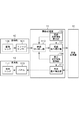
以下、本発明の第1の実施形態について、図面を参照しながら説明する。図1は、本実施形態における画像表示システムの構成を示すブロック図である。図1に示すように、本実施形態の画像表示システムは大きく分けて4つの機能部より構成されており、撮像映像を生成する撮像部10と、撮像映像および表示映像に対して画像処理を行う画像処理部11とを有する。さらに、撮像映像の内容に応じて重畳するCGデータを演算し、表示映像(表示画像)を作成する画像合成部12と、表示映像を表示し使用者に映像を視認させる表示部13とを有している。
[First Embodiment]
Hereinafter, a first embodiment of the present invention will be described with reference to the drawings. FIG. 1 is a block diagram showing the configuration of the image display system in this embodiment. As shown in FIG. 1, the image display system according to the present embodiment is roughly configured by four functional units, and performs an image processing on the
撮像部10および表示部13は本システムにおける画像表示装置に相当するヘッドマウントディスプレイ(以下、HMD)に備えられている。一方、画像処理部11および画像合成部12は本システムにおける情報処理装置に相当するPCに備えられている。HMDおよび情報処理装置(PC)は互いに有線方式または無線方式により接続され、それぞれCPU、ROM、RAM等のハードウェア構成を備える。そして、CPUがROMやHD等に格納されたプログラムを実行することにより、例えば、後述する各機能構成やフローチャートの処理が実現される。RAMは、CPUがプログラムを展開して実行するワークエリアとして機能する記憶領域を有する。ROMは、CPUが実行するプログラム等を格納する記憶領域を有する。
The
撮像部10と表示部13を含むHMDにおいては、HMDを頭部に装着した使用者が外界の映像にCGを重畳した映像を見ることができ、現実空間と仮想空間がリアルタイムに融合した複合現実感を体験することができる。撮像部10は、撮像光学系である撮像レンズ100と撮像素子であるイメージセンサ101とを含み、撮像レンズ100を介して結像された現実空間における被写体像をイメージセンサ101による光電変換によって撮像映像を取得する。イメージセンサ101は、例えば、CMOSイメージセンサやCCDイメージセンサなどの半導体センサから構成される。図2は撮像歪みと表示歪みを概念的に示しており、撮像部10より作成される撮像映像には、撮像レンズ100の光学特性によって、例えば、図2(a)のように被写体に対し幾何学的な歪みや色収差などが発生する。
In the HMD including the
表示部13は、パネル130と表示レンズ131とを含み、画像合成部12により生成された表示映像をパネル130に表示し、表示レンズ131を介して光束を観察対象へと結像させる。パネル130は、例えば、液晶表示パネルや有機ELパネル等の表示素子から構成される。観察対象が表示部13により観察する映像には、表示レンズ131の光学特性によって、例えば、図2(b)のように表示映像に対し幾何学的な歪みや色収差などが発生する。
The
続いて、情報処理装置側に設けられている画像処理部11および画像合成部12の機能について説明する。画像処理部11は、撮像部10より入力される撮像映像に対して映像切り出し処理を行う映像切り出し部110と、撮像光学特性を保持する撮像光学特性保持部112とを有する。さらに、撮像光学特性に基づき歪み補正を行う撮像歪み補正部111と、表示光学特性を保持する表示光学特性保持部114と、画像合成部12より入力される表示映像に対して表示光学特性に基づき歪み補正を行う表示歪み補正部113とを有する。各機能部の詳細については、後述する。
Next, the functions of the
画像合成部12は、画像処理部11より入力される撮像映像に対し、CGを重畳し表示映像として再度画像処理部11へと出力する機能を有する。また、画像合成部は、不図示のCG重畳位置推定手段によって推定されたHMD使用者の位置姿勢に関する情報に基づいて、撮像映像に対してCGおよび重畳する位置の計算を行う。そして、計算した画像位置にCGデータを合成し、表示映像として出力する。CG重畳位置推定手段による位置姿勢の推定手法としては、例えば、加速度センサや角速度センサおよび地磁気センサならびにGPSなどを用いる技術が存在する。また、撮像部10とは別の撮像センサを搭載し、その撮像映像内にあるマーカーを利用して位置姿勢を推定したり、また空間的な特徴点があればその特徴点から位置姿勢を推定することもできる。
The
また、画像合成部12は不図示の解像度変換部を有しており、表示画角に合わせて撮像解像度を変更し、撮像画角との整合を合わせるための解像度変換処理を行う場合がある。本実施形態では、解像度変換処理は画像合成部12により行われる構成としているが、本発明はこのような構成に限定されない。例えば、解像度変換処理を行わない構成としてもよいし、画像合成部12の後に解像度変換処理を行うようにしてもよい。
Further, the
このように、撮像部10により撮像された撮像映像が画像処理部11を介して画像合成部12へと入力され、撮像映像内の情報や他のセンサ情報等に基づいて、撮像映像にCGを重畳した表示映像が作成される。作成された表示映像は、再度、画像処理部11を介して表示部13へと入力され、使用者に現実世界と仮想世界がリアルタイムに融合した複合現実感を提供することができる。このとき、撮像映像に応じてCG重畳位置を推定する演算処理を行うため、システムを動作させる装置(例えばPC)の能力と撮像映像の解像度によっては所定のパフォーマンスが達成できない可能性がある。
In this way, the captured image captured by the
<画像処理部11の詳細>
ここで、本実施形態の画像表示システムにおいて、画像処理部11が有する撮像歪み補正部111および撮像光学特性保持部112の処理の詳細について説明する。撮像歪み補正部111は、撮像光学特性保持部112に保持された撮像光学特性の情報に基づいて、歪み補正処理を行う。撮像歪み補正部111と撮像光学特性保持部112は、例えば、同一基板に撮像歪み補正機能を搭載したLSIと撮像光学特性を保持するFLASH ROMを実装しFLASH ROMより撮像光学特性の情報を読み込むことで実現される。また、アプリケーションとして撮像歪み補正機能を実現する構成等としてもよく、撮像歪み補正を行える構成であれば特定の構成に限定されるものではない。
<Details of the
Here, in the image display system of the present embodiment, details of the processing of the imaging
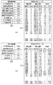
図3には、本実施形態において撮像光学特性保持部112に保持されている撮像光学特性および表示光学特性保持部114に保持されている表示光学特性の情報の一例を示しており、図3(a)が撮像光学特性の情報の一例である。同図に示すように、画像情報300として、撮像部10における撮像レンズ100およびイメージセンサ101の情報が保持されており、具体的には、解像度や画角、光軸中心の情報などが該当する。また、撮像歪みテーブル301には、撮像部10によって発生する歪みの局所情報が保持されており、任意の画像位置Pにおける撮像歪み補正量を示す参照位置Rや解像度に対する倍率変化情報などを示す倍率Mなどが含まれる。また、色収差が発生する場合には、色ごとの歪み情報も合わせて保持することで色収差補正を行うことも可能となる。
FIG. 3 shows an example of information on the image pickup optical characteristics held by the image pickup optical
撮像歪み補正部111は、図3(a)に示す歪み補正テーブルを撮像光学特性保持部112から読み込むことで、入力される撮像映像に対して歪み補正処理を実行する。歪み補正処理は、例えば、任意の注目画像位置おいて、注目画素位置に対応する歪み補正量を参照位置Rより算出し、算出された画素位置における撮像映像を出力として生成することで実現することができる。前述の歪み補正量の算出方法としては、バイリニア補間やスプライン補間など様々な手法が提案されており、本発明は特定の算出方法に限定されるものではない。
The image pickup
このように、撮像歪み補正部111は図3(a)のような歪み補正テーブルを読み込み、入力される撮像映像に対して歪み補正処理を実行するため、入力される撮像映像は、出力される撮像歪み補正後の撮像映像に対して、倍率が変化した状態となる。入出力前後で倍率が変動するということは入出力で解像度に変化がない場合、撮像画角が変化することと同義となる。すなわち、図3(a)の撮像光学特性を例に説明すると、水平最大変化倍率は−3.4%であるため、水平方向の画角は入力された撮像映像においては、49.39°×0.966=47.71°となる。本実施形態では、説明の簡素化のために歪みの最大変化倍率と画角の変化率を等価とみなして説明したが、計算の方法は焦点距離やイメージセンサの画素ピッチ、取り付け公差などを使ってもよい。
In this way, the image pickup
次に、本実施形態の画像表示システムにおいて、画像処理部11が有する表示歪み補正部113および表示光学特性保持部114の処理の詳細について説明する。表示歪み補正部113は、表示光学特性保持部114に保持される歪み補正に係る情報を読み込み、表示部13に表示する映像情報の歪み補正を行うものであり、その基本的な動作は撮像歪み補正部111と同様である。図3(b)には、表示光学特性保持部114に保持されている表示光学特性の情報の一例を示している。
Next, in the image display system of the present embodiment, details of the processing of the display
このように、撮像歪み補正部111および表示歪み補正部113において、各々の光学特性に応じて倍率変化、すなわち画角変化が生じる。そのため、表示部13に入力する表示映像は表示部13に入力する直前で切り出し処理を行い、解像度および画角を調整することが望ましい。しかしながら、切り出し処理を表示歪み補正部111の後に実行する従来構成のシステムにおいては、画像合成部12へと入力される撮像映像の解像度が高く、システムとしてオーバーヘッドを含んだ状態で処理がなされる。そのため、パフォーマンスが最適とはなっていなかった。そこで、本実施形態の構成では、以下に説明するように、画角演算処理部によりシステムに最適な切り出し解像度を算出し、撮像映像に対して切り出し処理を実行するようにする。
In this way, in the imaging
<映像切り出し部110の詳細>
次に、本実施形態に係る映像切り出し部110の処理の詳細について説明する。図4は、映像切り出し部110の機能構成を示す概略ブロック図である。映像切り出し部110は、画角変化演算部1100と切り出し実行部1101とにより構成されている。画角変化演算部1100は、撮像光学特性保持部112および表示光学特性保持部114から読み込んだ撮像光学特性情報および表示光学特性情報に基づいて、両歪み補正における入力映像の画角変化を計算し、システムに最適な切り出し解像度を算出する。また、切り出し実行部1101は、画角変化演算部1100で計算した切り出し解像度を元に、入力される撮像映像に対して切り出し処理を実行する。
<Details of
Next, the details of the processing of the
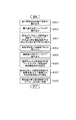
図5は、画角変化演算部1100による処理の流れを示すフローチャートである。なお、ここでは、図3(a),(b)で示した撮像光学特性、表示光学特性の情報の例を用いて説明を行う。図5のフローチャートにおいて、ステップS501で、画角変化演算部1100は、表示解像度DR(1920x1080)および表示画角DA(40x22.5°)を表示光学特性保持部114より読み込む。さらに、ステップS502において、画角変化演算部1100は、表示歪み補正テーブルDTを表示光学特性保持部114より読み込む。
FIG. 5 is a flowchart showing the flow of processing by the view angle
画角変化演算部1100は、これらの情報により、表示歪み補正部113の入力解像度PRと入力画角PAを算出することができる。例えば、簡易化のためにDR=PRとして説明をすると、前述したように歪みによる倍率の変動分が画角の変動分となる。すなわち、図3(b)の表示歪み補正テーブルによると、テーブルの最大変化倍率は、水平=0.1%、垂直=5.3%であるため、画角は、水平方向がDA=0.999×PA、垂直方向がDA=0.947×PAとして求めることができる。ステップS503では、このようにして、表示画角DA(40x22.5°)および表示歪み補正テーブルDTより、表示歪み補正前解像度PR(1920x1080)と、表示歪み補正前画角PA(40x23.7°)が決定される。
The view angle
次に、ステップS504において、画角変化演算部1100は撮像解像度CR(1920x1080)および撮像画角CA(49.4x29.4)を撮像光学特性保持部112より読み込む。さらに、ステップS505において、画角変化演算部1100は撮像歪み補正テーブルCTを撮像光学特性保持部112より読み込む。ステップS506において、画角変化演算部1100は、これらの情報に基づいて、まず撮像歪み補正部111への入力画角QAを算出する。その算出の方法としては、ステップS503と同様に、撮像歪み補正テーブルを参照し、撮像歪みによる倍率変化情報を元に算出する。ステップS506では、このようにして、撮像歪み補正前画角QA(41.16×24.5°)が決定する。
Next, in step S<b>504, the view angle
切り出す画角QAが決定すると、ステップS507において、画角変化演算部1100は、最終的な切り出し解像度QRを演算する。切り出し画角QA(41.16×24.5°)が決定しているため、撮像解像度CR(1920x1080)および撮像画角CA(49.4x29.4°)より、切り出し解像度QRが決定される。すなわち、水平方向QRx=1920×41.16/49.4=1600、垂直方向RQy=1080×24.5/29.4=900となるため、QR(1600x900)として決定される。最後に、ステップS508において、画角変化演算部1100は切り出し解像度QR(1600x900)を切り出し実行部1101へと送信する。
When the angle of view QA to be cut out is determined, in step S507, the angle of view
切り出し実行部1101は、画角変化演算部1100より入力される切り出し解像度の情報を元に撮像映像の一部を切り出す。切り出し位置は、例えば、撮像の光軸中心位置を切り出し前後で揃えた位置等として、切り出される。
The
図6は、本実施形態の画像処理システムの一連の処理において、映像データの解像度と画角を示す図である。同図には、比較対象として、上述した従来構成のシステムにおける解像度と画角も併せて記載している。図6において、「A.イメージセンサからの出力」は、図1のイメージセンサ101から映像切り出し部110へと転送される撮像映像の解像度と画角を示している。「B.撮像歪み補正前切り出し処理からの出力」は、映像切り出し部110から撮像歪み補正部111へと転送される撮像映像の解像度と画角を示している。
FIG. 6 is a diagram showing the resolution and angle of view of video data in a series of processes of the image processing system of this embodiment. In the same figure, the resolution and the angle of view in the above-described conventional system are also shown for comparison. 6, “A. Output from image sensor” indicates the resolution and the angle of view of the captured image transferred from the image sensor 101 of FIG. 1 to the
また、「C.撮像歪み補正部からの出力」は、撮像歪み補正部111から画像合成部12へと転送される撮像映像の解像度と画角を示している。「D.画像合成部からの出力」は、画像合成部12から表示歪み補正部113へと転送される表示映像の解像度と画角を示している。ここで、CからDの間で解像度が増加しているのは、前述した画像合成部12における解像度変換処理によるものである。この処理では、撮像の画角を維持したまま表示の解像度に合わせた映像を生成している。
Further, “C. Output from imaging distortion correction unit” indicates the resolution and angle of view of the captured video transferred from the imaging
また、「E.表示歪み補正部からの出力」は、表示歪み補正部113から出力される表示映像の解像度と画角を示している。「F.表示歪み補正後の切り出し処理からの出力」は、従来構成の画像表示システムにおいて、表示歪み補正部とパネルとの間に配置された切り出し処理部から出力される表示映像の解像度と画角を示している。最後に、「G.表示パネルへの入力」は、パネル130へ入力される表示映像の解像度と画角を示している。なお、従来構成のシステムにおいてはBの出力がなく、本実施形態のシステムにおいてはFの出力がないため、それぞれの解像度と画角については記載していない。
Further, “E. Output from display distortion correction unit” indicates the resolution and the angle of view of the display image output from the display
ここで、図6の「G.表示パネルへの入力」に注目すると、従来構成と本実施形態とで解像度および画角について差異はない。一方、「C.撮像歪み補正部からの出力」では、従来構成における解像度が1920x1080であるのに対し、本実施形態の解像度は1600x900となっており、本実施形態の方が、約30%解像度が低いことがわかる。このように、表示する映像の解像度および画角に影響することなく、表示部への入力より前段の処理において転送、処理される映像データのデータ量を抑え、画像合成部12への入力解像度を最適にすることができる。これにより、本実施形態では、システム全体のパフォーマンスを最適にすることが可能となる。
Here, focusing on “G. Input to display panel” in FIG. 6, there is no difference in resolution and angle of view between the conventional configuration and this embodiment. On the other hand, in “C. Output from imaging distortion correction unit”, the resolution in the conventional configuration is 1920×1080, whereas the resolution in this embodiment is 1600×900, and the resolution in this embodiment is about 30%. It turns out that is low. In this way, without affecting the resolution and the angle of view of the displayed video, the data amount of the video data transferred and processed in the processing preceding the input to the display unit is suppressed, and the input resolution to the
なお、本実施形態では、上述したように、撮像光学系と表示光学系の情報を取得し、その情報から撮像光学系による歪みと表示光学系の歪みの両方を補正するようにしているが、いずれか一方のみの歪みに着目し、その一方のみを補正する形態でもよい。 Note that in the present embodiment, as described above, the information of the image pickup optical system and the display optical system is acquired, and both the distortion of the image pickup optical system and the distortion of the display optical system are corrected from the information, It is also possible to focus on only one of the distortions and correct only one of them.
以上、本実施形態によれば、撮像光学特性と表示光学特性に応じて切り出し解像度を算出し、撮像歪み補正前に切り出し処理を行うことで、画像合成部への入力解像度を抑制することができる。このため、転送、処理される映像データのデータ量が抑制され、システムを動作させる装置への負荷が軽減し、画像表示システム全体のパフォーマンスを最適にすることが可能となる。 As described above, according to the present embodiment, the cutout resolution is calculated according to the image pickup optical characteristic and the display optical characteristic, and the cutout process is performed before the image pickup distortion correction, whereby the input resolution to the image combining unit can be suppressed. .. Therefore, the amount of video data to be transferred and processed is suppressed, the load on the device that operates the system is reduced, and the performance of the entire image display system can be optimized.
[第1の実施形態の変形例]
ここで、上述した第1の実施形態の変形例について説明する。図7は、本変形例に係る画像表示システムを示すブロック図である。本変形例が、上述した第1の実施形態と相違する点は、画像処理部11の内部構成である。具体的には、本変形例では、撮像歪み補正処理と表示歪み補正処理を共通歪み補正部702により共通で処理するとともに、共通歪みテーブル演算部701を備えている。また、映像切り出し部700は、共通歪みテーブル演算部701からの入力により切り出し解像度を決定する構成としている。
[Modification of First Embodiment]
Here, a modification of the above-described first embodiment will be described. FIG. 7 is a block diagram showing an image display system according to this modification. This modification is different from the above-described first embodiment in the internal configuration of the
共通歪みテーブル演算部701は、撮像光学特性保持部112と表示光学特性保持部114から読み込んだテーブル情報を元に新たにテーブルを生成する。そして、映像切り出し部700は、新たに生成したテーブルを用い、上述の第1の実施形態と同様にして切り出し解像度を決定する。これにより、撮像光学特性と表示光学特性を含めて切り出し領域を決定することができる。このように、本変形例では、共通の歪み補正処理を行う場合においてもシステム全体のパフォーマンスを最適にすることが可能となる。
The common distortion
[その他の実施形態]
上述の説明では、HMD側が撮像部10と表示部13とを備え、情報処理装置(PC)側が画像処理部11と画像合成部12とを備える構成を示した。しかしながら、本発明は、このような形態に限定されるものではなく、例えば、上記4つの機能部の全てをHMD側が有し、HMD側だけで全ての処理が実行されるように構成してもよい。
[Other Embodiments]
In the above description, the HMD side includes the
また、上述の説明では、撮像光学特性保持部112と表示光学特性保持部114とがそれぞれ別々に構成された例について説明したが、撮像光学特性情報と表示光学特性情報とを単一の保持部で保持するような構成であってもよい。また、このような情報は、上述の実施形態に係る画像表示システムの外部に保持され、それを取得して利用するような形態であってもよい。
Further, in the above description, an example in which the image pickup optical
また、本発明は、上記実施形態の機能を実現するソフトウェア(プログラム)を、ネットワーク又は各種記憶媒体を介してシステム或いは装置に供給し、そのシステム或いは装置のコンピュータ(又はCPUやMPU等)がプログラムを読出し実行する処理である。また、本発明は、複数の機器から構成されるシステムに適用しても、1つの機器からなる装置に適用してもよい。本発明は上記実施例に限定されるものではなく、本発明の趣旨に基づき種々の変形(各実施例の有機的な組合せを含む)が可能であり、それらを本発明の範囲から除外するものではない。即ち、上述した各実施例及びその変形例を組み合わせた構成も全て本発明に含まれるものである。 Further, the present invention supplies software (program) that realizes the functions of the above-described embodiments to a system or apparatus via a network or various storage media, and the computer (or CPU, MPU, etc.) of the system or apparatus executes the program. Is a process of reading out and executing. Further, the present invention may be applied to a system including a plurality of devices or an apparatus including one device. The present invention is not limited to the above-mentioned embodiments, and various modifications (including organic combinations of the embodiments) are possible based on the spirit of the present invention, and exclude them from the scope of the present invention. is not. That is, the present invention includes all configurations that combine the above-described embodiments and their modifications.
10 撮像部
11 画像処理部
12 画像合成部
13 表示部
10
Claims (10)
前記撮像部の撮像光学系に係る情報と前記表示部の表示光学系に係る情報とに基づいて、前記撮像された画像に対して、前記撮像光学系による画像の歪みの補正、及び、前記表示光学系による画像の歪みの補正の両方が段階的に実行された場合に、前記撮像された画像に生じる変化の情報に基づいて、前記撮像された画像の一部を切り出す切り出し手段と、
前記切り出された画像に対して、前記撮像光学系による画像の歪みを補正する処理と前記表示光学系による画像の歪みを補正する処理を段階的に実行する補正手段と、
を有することを特徴とする情報処理装置。 An information processing apparatus, comprising: an image pickup unit for picking up an image; and a display unit for displaying a display image to be displayed to a user, and which is connected to an image display device which is mounted on the head of the user and used. There
Correction of image distortion by the imaging optical system with respect to the captured image based on information about the imaging optical system of the imaging unit and information about the display optical system of the display unit , and the display. When both of the distortion correction of the image by the optical system is executed stepwise , based on the information of the change occurring in the captured image, a cutting-out means for cutting out a part of the captured image,
Correction means for performing stepwise a process of correcting the image distortion by the imaging optical system and a process of correcting the image distortion by the display optical system on the cut-out image;
An information processing device comprising:
前記補正手段は、前記取得手段により取得された前記変化の情報に基づいて画像の歪みを補正することを特徴とする請求項1に記載の情報処理装置。 An acquisition that acquires information on the change as a result of calculating information common to the imaging optical system and information common to the display optical system based on the information on the imaging optical system and the information on the display optical system. Further having means,
The information processing apparatus according to claim 1 , wherein the correction unit corrects the image distortion based on the change information acquired by the acquisition unit.
前記撮像部の撮像光学系に係る情報と前記表示部の表示光学系に係る情報との少なくとも一方に基づいて、前記撮像光学系と前記表示光学系との少なくとも一方による前記撮像された画像の歪みを補正した場合に、前記撮像された画像に生じる変化の情報に基づいて、前記撮像された画像の一部を切り出す切り出し手段と、
前記切り出された画像に対して、前記撮像光学系と前記表示光学系との少なくとも一方による歪みを補正する処理を実行する補正手段と、
前記撮像光学系と前記表示光学系における解像度、画角、および注目画素位置における補正量とに基づいて、前記撮像光学系に係る情報と前記表示光学系に共通した情報を演算した結果として、前記変化の情報を取得する取得手段と、を有し、
前記補正手段は、前記取得手段により取得された前記変化の情報に基づいて画像の歪みを補正することを特徴とする情報処理装置。 An information processing apparatus, comprising: an image pickup unit for picking up an image; and a display unit for displaying a display image to be displayed to a user, and which is connected to an image display device which is mounted on the head of the user and used. There
Distortion of the captured image by at least one of the imaging optical system and the display optical system, based on at least one of the information about the imaging optical system of the imaging unit and the information about the display optical system of the display unit. And a cutout unit that cuts out a part of the imaged image based on information on a change occurring in the imaged image,
A correction unit that performs a process of correcting the distortion caused by at least one of the image pickup optical system and the display optical system on the clipped image,
Based on the resolution in the image pickup optical system and the display optical system, the angle of view, and the correction amount at the pixel position of interest, as a result of calculating information related to the image pickup optical system and information common to the display optical system, An acquisition means for acquiring information on the change,
The information processing apparatus , wherein the correction unit corrects the image distortion based on the change information acquired by the acquisition unit.
前記補正手段は、前記合成手段によって生成された合成画像に対し、さらに前記表示光学系による歪みを補正するものであって、
前記表示部には、前記補正された合成画像が表示されることを特徴する請求項1から5のいずれか1項に記載の情報処理装置。 First, the image forming apparatus further includes a combining unit that generates a combined image in which CG data is superimposed on the image obtained by correcting the distortion caused by the image pickup optical system by the correcting unit with respect to the cut out image .
The correction means further corrects the distortion caused by the display optical system with respect to the combined image generated by the combining means,
Wherein the display unit, the information processing apparatus according to any one of claims 1 to 5, characterized in that the corrected synthesized image is displayed.
前記撮像部の撮像光学系に係る情報と表示部の表示光学系に係る情報とに基づいて、前記撮像された画像に対して、前記撮像光学系による画像の歪みの補正、及び、前記表示光学系による画像の歪みの補正の両方が段階的に実行された場合に、前記撮像された画像に生じる変化の情報に基づいて、前記撮像された画像の一部を切り出す切り出し手段と、
前記切り出された画像に対して、前記撮像光学系による画像の歪みを補正する処理と前記表示光学系による画像の歪みを補正する処理を段階的に実行する補正手段と、
前記補正された画像に基づいて、使用者に表示すべき表示画像を表示する表示部と、を有し、前記使用者の頭部に装着されて使用されることを特徴とする画像表示装置。 An image capturing unit for capturing an image,
Correction of image distortion by the imaging optical system with respect to the captured image, based on information about the imaging optical system of the imaging unit and information about the display optical system of the display unit, and the display optical system. When both of the distortion correction of the image by the system are performed stepwise , based on the information of the change that occurs in the captured image, a cutting-out means for cutting out a part of the captured image,
Correction means for performing stepwise a process of correcting the image distortion by the imaging optical system and a process of correcting the image distortion by the display optical system on the cut-out image;
An image display device, comprising: a display unit that displays a display image to be displayed to a user based on the corrected image, and is mounted on the head of the user for use.
前記撮像部の撮像光学系に係る情報と表示部の表示光学系に係る情報とに基づいて、前記撮像された画像に対して、前記撮像光学系による画像の歪みの補正、及び、前記表示光学系による画像の歪みの補正の両方が段階的に実行された場合に、前記撮像された画像に生じる変化の情報に基づいて、前記撮像された画像の一部を切り出す切り出し手段と、
前記切り出された画像に対して、前記撮像光学系による画像の歪みを補正する処理と前記表示光学系による画像の歪みを補正する処理を段階的に実行する補正手段と、
前記補正された画像に基づいて、使用者に表示すべき表示画像を、前記使用者の頭部に装着されて使用される画像表示装置に表示する表示部と、を有することを特徴とする画像表示システム。 An image capturing unit for capturing an image,
Correction of image distortion by the imaging optical system with respect to the captured image, based on information about the imaging optical system of the imaging unit and information about the display optical system of the display unit, and the display optical system. When both of the distortion correction of the image by the system are performed stepwise , based on the information of the change that occurs in the captured image, a cutting-out means for cutting out a part of the captured image,
Correction means for performing stepwise a process of correcting the image distortion by the imaging optical system and a process of correcting the image distortion by the display optical system on the cut-out image;
An image comprising: a display unit that displays a display image to be displayed to the user on the image display device that is mounted on the head of the user and is used based on the corrected image. Display system.
前記撮像部の撮像光学系に係る情報と前記表示部の表示光学系に係る情報とに基づいて、前記撮像された画像に対して、前記撮像光学系による画像の歪みの補正、及び、前記表示光学系による画像の歪みの補正の両方が段階的に実行された場合に、前記撮像された画像に生じる変化の情報に基づいて、前記撮像された画像の一部を切り出すステップと、
前記切り出された画像に対して、前記撮像光学系による画像の歪みを補正する処理と前記表示光学系による画像の歪みを補正する処理を段階的に実行する補正ステップと、
を有することを特徴とする情報処理方法。 In an information processing device including an image pickup unit for picking up an image and a display unit for displaying a display image to be displayed to a user, which is connected to an image display device which is mounted on the head of the user and is used. An information processing method,
Correction of image distortion by the imaging optical system with respect to the captured image based on information about the imaging optical system of the imaging unit and information about the display optical system of the display unit , and the display. When both the correction of the distortion of the image by the optical system is performed stepwise , based on the information of the change that occurs in the captured image, a step of cutting out a part of the captured image,
With respect to the cut-out image, a correction step of performing stepwise a process of correcting image distortion by the imaging optical system and a process of correcting image distortion by the display optical system,
An information processing method comprising:
前記撮像部の撮像光学系に係る情報と前記表示部の表示光学系に係る情報との少なくとも一方に基づいて、前記撮像光学系と前記表示光学系との少なくとも一方による前記撮像された画像の歪みを補正した場合に、前記撮像された画像に生じる変化の情報に基づいて、前記撮像された画像の一部を切り出すステップと、
前記切り出された画像に対して、前記撮像光学系と前記表示光学系との少なくとも一方による歪みを補正する処理を実行するステップと、
前記撮像光学系と前記表示光学系における解像度、画角、および注目画素位置における補正量とに基づいて、前記撮像光学系に係る情報と前記表示光学系に共通した情報を演算した結果として、前記変化の情報を取得する取得ステップと、を有し、
前記補正する処理を実行するステップでは、前記取得ステップで取得された前記変化の情報に基づいて画像の歪みを補正することを特徴とする情報処理方法。 In an information processing device including an image pickup unit for picking up an image and a display unit for displaying a display image to be displayed to a user, which is connected to an image display device which is mounted on the head of the user and is used. An information processing method,
Distortion of the captured image by at least one of the imaging optical system and the display optical system, based on at least one of the information about the imaging optical system of the imaging unit and the information about the display optical system of the display unit. A step of cutting out a part of the imaged image based on information on a change occurring in the imaged image when correcting
A step of correcting a distortion caused by at least one of the image pickup optical system and the display optical system with respect to the cut-out image;
Based on the resolution in the image pickup optical system and the display optical system, the angle of view, and the correction amount at the pixel position of interest, as a result of calculating information related to the image pickup optical system and information common to the display optical system, An acquisition step of acquiring change information,
An information processing method , wherein in the step of executing the correction processing, the image distortion is corrected based on the change information acquired in the acquisition step .
Priority Applications (1)
| Application Number | Priority Date | Filing Date | Title |
|---|---|---|---|
| JP2016075487A JP6711670B2 (en) | 2016-04-04 | 2016-04-04 | Information processing device, image display device, image display system, and information processing method |
Applications Claiming Priority (1)
| Application Number | Priority Date | Filing Date | Title |
|---|---|---|---|
| JP2016075487A JP6711670B2 (en) | 2016-04-04 | 2016-04-04 | Information processing device, image display device, image display system, and information processing method |
Publications (3)
| Publication Number | Publication Date |
|---|---|
| JP2017188757A JP2017188757A (en) | 2017-10-12 |
| JP2017188757A5 JP2017188757A5 (en) | 2019-05-09 |
| JP6711670B2 true JP6711670B2 (en) | 2020-06-17 |
Family
ID=60046620
Family Applications (1)
| Application Number | Title | Priority Date | Filing Date |
|---|---|---|---|
| JP2016075487A Expired - Fee Related JP6711670B2 (en) | 2016-04-04 | 2016-04-04 | Information processing device, image display device, image display system, and information processing method |
Country Status (1)
| Country | Link |
|---|---|
| JP (1) | JP6711670B2 (en) |
Families Citing this family (3)
| Publication number | Priority date | Publication date | Assignee | Title |
|---|---|---|---|---|
| JP7365183B2 (en) | 2019-03-29 | 2023-10-19 | 株式会社ソニー・インタラクティブエンタテインメント | Image generation device, head mounted display, content processing system, and image display method |
| JP7429515B2 (en) | 2019-03-29 | 2024-02-08 | 株式会社ソニー・インタラクティブエンタテインメント | Image processing device, head-mounted display, and image display method |
| US11126001B2 (en) | 2019-03-29 | 2021-09-21 | Sony Interactive Entertainment Inc. | Image generating apparatus, head-mounted display, content processing system and image displaying method |
Family Cites Families (5)
| Publication number | Priority date | Publication date | Assignee | Title |
|---|---|---|---|---|
| JP4693552B2 (en) * | 2005-08-30 | 2011-06-01 | キヤノン株式会社 | Display device, control device, and control method |
| JP5074777B2 (en) * | 2006-05-22 | 2012-11-14 | キヤノン株式会社 | Display device with imaging function, image processing device, image processing method, and image display system |
| JP5231799B2 (en) * | 2007-12-25 | 2013-07-10 | キヤノン株式会社 | Control device, display device and control method thereof, mixed reality system, and computer program |
| JP2011203446A (en) * | 2010-03-25 | 2011-10-13 | Fujifilm Corp | Head-mounted display device |
| JP5733088B2 (en) * | 2011-08-01 | 2015-06-10 | 大日本印刷株式会社 | Movie presentation device |
-
2016
- 2016-04-04 JP JP2016075487A patent/JP6711670B2/en not_active Expired - Fee Related
Also Published As
| Publication number | Publication date |
|---|---|
| JP2017188757A (en) | 2017-10-12 |
Similar Documents
| Publication | Publication Date | Title |
|---|---|---|
| JP5917054B2 (en) | Imaging apparatus, image data processing method, and program | |
| JP5388534B2 (en) | Image processing apparatus and method, head-mounted display, program, and recording medium | |
| US9313411B2 (en) | Camera, distortion correction device and distortion correction method | |
| WO2012114639A1 (en) | Object display device, object display method, and object display program | |
| JP6478511B2 (en) | Image processing method, image processing apparatus, compound eye imaging apparatus, image processing program, and storage medium | |
| US8988546B2 (en) | Image processing device, image processing method, image capturing device, and program | |
| JP2012138771A (en) | Video signal processing device and video signal processing method | |
| JP6711670B2 (en) | Information processing device, image display device, image display system, and information processing method | |
| US9143756B2 (en) | Camera module, photographing method, and electronic apparatus | |
| JP6594170B2 (en) | Image processing apparatus, image processing method, image projection system, and program | |
| JP6971590B2 (en) | Image processing equipment, image processing methods and programs | |
| JP6904684B2 (en) | Image processing equipment, image processing methods, and programs | |
| JP6862210B2 (en) | Image processing equipment, image processing system, image processing method and program | |
| JP5535099B2 (en) | Camera module and image recording method | |
| JP6732440B2 (en) | Image processing apparatus, image processing method, and program thereof | |
| JPWO2018189880A1 (en) | Information processing apparatus, information processing system, and image processing method | |
| JP6257289B2 (en) | Image processing apparatus, imaging apparatus including the same, and image processing method | |
| JP7053434B2 (en) | Image processing device and image processing method | |
| US10616504B2 (en) | Information processing device, image display device, image display system, and information processing method | |
| JP5645704B2 (en) | Image processing apparatus and control method thereof | |
| JP6433154B2 (en) | Image processing apparatus and imaging apparatus | |
| JP6622537B2 (en) | Image processing apparatus, image processing system, and image processing method | |
| JP6645949B2 (en) | Information processing apparatus, information processing system, and information processing method | |
| JP6564939B2 (en) | Wide viewing angle image processing apparatus and method | |
| JP2014038440A (en) | Image processing device, image processing method, program, and image processing system |
Legal Events
| Date | Code | Title | Description |
|---|---|---|---|
| A521 | Request for written amendment filed |
Free format text: JAPANESE INTERMEDIATE CODE: A523 Effective date: 20190319 |
|
| A621 | Written request for application examination |
Free format text: JAPANESE INTERMEDIATE CODE: A621 Effective date: 20190319 |
|
| A977 | Report on retrieval |
Free format text: JAPANESE INTERMEDIATE CODE: A971007 Effective date: 20191220 |
|
| A131 | Notification of reasons for refusal |
Free format text: JAPANESE INTERMEDIATE CODE: A131 Effective date: 20200107 |
|
| A521 | Request for written amendment filed |
Free format text: JAPANESE INTERMEDIATE CODE: A523 Effective date: 20200303 |
|
| TRDD | Decision of grant or rejection written | ||
| A01 | Written decision to grant a patent or to grant a registration (utility model) |
Free format text: JAPANESE INTERMEDIATE CODE: A01 Effective date: 20200428 |
|
| A61 | First payment of annual fees (during grant procedure) |
Free format text: JAPANESE INTERMEDIATE CODE: A61 Effective date: 20200528 |
|
| R151 | Written notification of patent or utility model registration |
Ref document number: 6711670 Country of ref document: JP Free format text: JAPANESE INTERMEDIATE CODE: R151 |
|
| LAPS | Cancellation because of no payment of annual fees |