JP5388534B2 - Image processing apparatus and method, head-mounted display, program, and recording medium - Google Patents
Image processing apparatus and method, head-mounted display, program, and recording medium Download PDFInfo
- Publication number
- JP5388534B2 JP5388534B2 JP2008263056A JP2008263056A JP5388534B2 JP 5388534 B2 JP5388534 B2 JP 5388534B2 JP 2008263056 A JP2008263056 A JP 2008263056A JP 2008263056 A JP2008263056 A JP 2008263056A JP 5388534 B2 JP5388534 B2 JP 5388534B2
- Authority
- JP
- Japan
- Prior art keywords
- display
- pixel
- image
- color
- image processing
- Prior art date
- Legal status (The legal status is an assumption and is not a legal conclusion. Google has not performed a legal analysis and makes no representation as to the accuracy of the status listed.)
- Active
Links
Images


Classifications
-
- G—PHYSICS
- G02—OPTICS
- G02B—OPTICAL ELEMENTS, SYSTEMS OR APPARATUS
- G02B27/00—Optical systems or apparatus not provided for by any of the groups G02B1/00 - G02B26/00, G02B30/00
- G02B27/01—Head-up displays
- G02B27/017—Head mounted
-
- G—PHYSICS
- G02—OPTICS
- G02B—OPTICAL ELEMENTS, SYSTEMS OR APPARATUS
- G02B27/00—Optical systems or apparatus not provided for by any of the groups G02B1/00 - G02B26/00, G02B30/00
- G02B27/01—Head-up displays
- G02B27/0101—Head-up displays characterised by optical features
- G02B2027/0112—Head-up displays characterised by optical features comprising device for genereting colour display
- G02B2027/0116—Head-up displays characterised by optical features comprising device for genereting colour display comprising devices for correcting chromatic aberration
-
- G—PHYSICS
- G02—OPTICS
- G02B—OPTICAL ELEMENTS, SYSTEMS OR APPARATUS
- G02B27/00—Optical systems or apparatus not provided for by any of the groups G02B1/00 - G02B26/00, G02B30/00
- G02B27/01—Head-up displays
- G02B27/0101—Head-up displays characterised by optical features
- G02B2027/014—Head-up displays characterised by optical features comprising information/image processing systems
Description
本発明は、画像処理装置およびその方法、頭部装着型ディスプレイ、プログラム、記録媒体に関し、特に、ディスプレイの各画素に含まれる原色エレメントの位置が色ごとに異なる構成における色収差を補正する技術に関する。 The present invention relates to an image processing apparatus and method, a head-mounted display, a program, and a recording medium, and more particularly to a technique for correcting chromatic aberration in a configuration in which the positions of primary color elements included in each pixel of the display are different for each color.
近年、現実世界と仮想世界をリアルタイムかつシームレスに融合させる技術として複合現実感、いわゆるMR(Mixed Reality)技術が知られている。そして、MR技術の1つに、ビデオシースルー型HMDを利用して、HMD装着者の瞳位置から観察される被写体をビデオカメラなどで撮像し、その撮像画像にCGを重畳した複合現実画像をHMD装着者に対して表示する技術が知られている。なお、HMDはHead Mounted Display(頭部装着型ディスプレイ)の略称であり、CGはComputer Graphics(コンピュータ・グラフィックス)の略称である。ビデオシースルー型HMDでは、CCD等の電荷結合素子により被写体を撮像して該被写体のデジタル画像データを得るとともに、CG画像を重畳したMR画像(複合現実画像)を液晶等の表示デバイスを介して装着者に表示する構成になっている。 In recent years, a mixed reality, so-called MR (Mixed Reality) technology has been known as a technology for seamlessly combining the real world and the virtual world in real time. As one of MR techniques, a video see-through HMD is used to capture a subject observed from the pupil position of the HMD wearer with a video camera or the like, and a mixed reality image in which CG is superimposed on the captured image is an HMD. A technique for displaying to a wearer is known. HMD is an abbreviation for Head Mounted Display (head-mounted display), and CG is an abbreviation for Computer Graphics (computer graphics). In a video see-through type HMD, a subject is imaged by a charge coupled device such as a CCD to obtain digital image data of the subject, and an MR image (mixed reality image) on which a CG image is superimposed is mounted via a display device such as a liquid crystal. Display to the user.
このような頭部に装着するHMDは小型化・軽量化が望まれる。しかし、廉価なレンズや少ない枚数のレンズで光学系を構成した場合、レンズの収差に起因して、表示する画像の画質を良好に保持できないおそれがある。例えば、レンズの歪曲収差に起因して、樽型の像が得られたり、糸巻型の像が得られたりしてしまうことがある。また、レンズの倍率色収差に起因して、被写体像の境界部分に赤や青や緑の色にじみが生じてしまうことがある。このため、上記のようなレンズの収差に起因した被写体像の画質低下を補正する必要がある。 The HMD to be mounted on such a head is desired to be reduced in size and weight. However, when an optical system is configured with an inexpensive lens or a small number of lenses, there is a possibility that the image quality of the displayed image cannot be satisfactorily maintained due to the aberration of the lens. For example, a barrel-shaped image or a pincushion-type image may be obtained due to lens distortion. Further, due to the chromatic aberration of magnification of the lens, red, blue, or green color blur may occur at the boundary portion of the subject image. For this reason, it is necessary to correct the deterioration of the image quality of the subject image due to the aberration of the lens as described above.
なお、光学的なアプローチにより各種の収差を補正する方式は、一般的にサイズや重量が大きいため、小型化・軽量化が望まれるHMDの用途に適合しないことが多い。このため、撮像および表示の光学系に関しても信号処理による電子的な補正を施すことで、廉価なレンズの採用を可能にしたり、レンズ枚数を減らしたりすることが検討されている。 Note that a method for correcting various aberrations by an optical approach generally has a large size and weight, and thus is often not suitable for use in an HMD that is desired to be reduced in size and weight. For this reason, it has been studied to make it possible to adopt an inexpensive lens or reduce the number of lenses by applying electronic correction by signal processing for the imaging and display optical systems.
光学系の各種収差のうち歪曲収差と倍率色収差を信号処理によって補正する技術は、大きく3種類に分類することができる。以下、それぞれの概要を説明する。 Techniques for correcting distortion and lateral chromatic aberration among various aberrations of the optical system by signal processing can be roughly classified into three types. The outline of each will be described below.
1つ目は、アドレス変換による歪曲収差、倍率色収差の補正処理である。アドレス変換は、撮像系においては理想的な光学系で得られる結像位置と実際の収差の影響を受けた結像位置との対応関係に基づき、歪んだ画像を理想的な画像位置へと移動する手法である。変換前後の画素位置に関する対応関係をテーブル化し、単にメモリの読み出しと書き込みの対応関係(アドレス)を変換するものから、精度の高い変換後の座標データを保持するものまで様々である。表示系においても表示する画素と実際に表示される位置との対応関係によって表示位置を変換する。このように画素の変換を行えば歪曲収差の補正が、画素を構成する色毎に変換を行われた場合は、倍率色収差を補正することができる。 The first is correction processing for distortion and lateral chromatic aberration by address conversion. Address conversion moves the distorted image to the ideal image position based on the correspondence between the image position obtained by the ideal optical system and the image position affected by the actual aberration. It is a technique to do. The correspondence relationship between the pixel positions before and after the conversion is tabulated, and it varies from simply converting the correspondence (address) between reading and writing of the memory to holding highly accurate coordinate data after conversion. Also in the display system, the display position is converted according to the correspondence between the pixel to be displayed and the actual display position. If the pixels are converted in this way, the distortion chromatic aberration can be corrected when the distortion is corrected for each color constituting the pixel.
2つ目は、解像度変換による倍率色収差の補正処理で、色によって変倍率が異なることを利用して基準となる色に対して、拡大、縮小処理を適用することで色にじみの少ない画像を得る手法である。 The second is correction processing for chromatic aberration of magnification by resolution conversion. By using the fact that the scaling factor varies depending on the color, an enlargement / reduction process is applied to the reference color to obtain an image with less color blur. It is a technique.
3つ目は、近似多項式を利用した歪曲収差、各色の歪曲収差補正による倍率色収差の補正処理であり、補正パラメータを係数とする高次の多項式で近似して変換後の座標群を算出するものである。 The third is correction processing of distortion aberration and magnification chromatic aberration by correction of distortion aberration of each color using an approximate polynomial, and calculates a coordinate group after conversion by approximation with a high-order polynomial having a correction parameter as a coefficient. It is.
比較的汎用性が高く、高精度な座標変換が可能なのはアドレス変換である。ただし、画像サイズが大きい場合や、高い変換精度が求められる場合においては、変換後の座標との対応関係を格納した参照テーブルのサイズが肥大化してしまう。 Address conversion is relatively versatile and enables highly accurate coordinate conversion. However, when the image size is large or when high conversion accuracy is required, the size of the reference table storing the correspondence relationship with the coordinate after conversion is enlarged.
これに対して、複数色の一色を基準色として他の色は基準色との差分を格納する構成や、光学系の対称性を利用してテーブルのサイズを削減する構成が特許文献1、特許文献2に開示されている。例えば、画像に対して光学系が左右方向または上下方向に対称であれば、表示対象部分の参照値を一方向側についてのみ生成することが可能なため、テーブルサイズを半減することができる。さらに、光学系が上下左右とも対称であれば(すなわち、回転対称系であれば)、テーブルサイズを1/4に低減することも可能である。
しかしながら上述した従来の技術においては、以下のような課題が存在する。すなわち、表示デバイスからの光を目に導く光学系が回転対称や光学原点を通る軸による対称となっても、表示デバイスを構成する画素の並びが左右または上下方向で軸に対して対称とならない場合がある。例えば、単板のTFT(Thin−Film Transistor)液晶や有機EL等の表示パネルがこのような表示デバイスに該当する。なお、これらの表示デバイスは小型・軽量化のためHMDでは採用されることが多い。 However, the conventional techniques described above have the following problems. That is, even if the optical system that guides the light from the display device to the eye is rotationally symmetric or symmetric with respect to the axis passing through the optical origin, the arrangement of the pixels constituting the display device is not symmetric with respect to the axis in the horizontal or vertical direction. There is a case. For example, a display panel such as a single-plate TFT (Thin-Film Transistor) liquid crystal or an organic EL corresponds to such a display device. Note that these display devices are often used in HMDs to reduce size and weight.
TFT液晶パネルの各画素は、原色光を発する原色エレメントとして、例えば、R(赤)、G(緑)、B(青)の三色のフィルタを有している。液晶パネルを正面から見たときに各フィルタがこの順序で左から右に各画素内に配置されているTFT液晶パネルにおいては、光学原点を通る垂直な軸に対して、液晶パネルの右側ではBが外側に位置するが、左側ではRが外側に位置することになる。このような構成に対して、回転対称や軸対称の補正値を適用すると、画素の並び方向にズレが生じてしまう。ズレ方は使用する光学素子に依存するが、例えば各画素がRGBの三色のフィルタを有する構成においては、RとBのズレ量は左右で2/3画素分ずれることになる。一般にHMDの光学系の解像度は1画素程度の分解能を持つようにしている場合が多いが、色ズレに関しては0.1画素から0.3画素程度の色のズレが視覚的に偽色や色にじみの発生として認められることが実験によって確認されている。 Each pixel of the TFT liquid crystal panel has, for example, three color filters of R (red), G (green), and B (blue) as primary color elements that emit primary color light. In a TFT liquid crystal panel in which the filters are arranged in each pixel in this order from left to right when the liquid crystal panel is viewed from the front, B is on the right side of the liquid crystal panel with respect to a vertical axis passing through the optical origin. Is located outside, but on the left side, R is located outside. When a rotationally symmetric or axially symmetric correction value is applied to such a configuration, a deviation occurs in the pixel arrangement direction. For example, in a configuration in which each pixel has RGB three-color filters, the amount of deviation between R and B is shifted by 2/3 pixels on the left and right. In general, the resolution of the optical system of the HMD is often set to have a resolution of about 1 pixel. However, with regard to the color deviation, a color deviation of about 0.1 to 0.3 pixels is visually a false color or color. It has been confirmed by experiments that it is recognized as the occurrence of bleeding.
したがって、上記のTFT液晶パネルのように各原色を発するエレメント(色フィルタや発光部等)が各画素内でそれぞれ別個に設けられている場合、従来手法により光学収差を補正すると、ユーザが知覚できる程度に偽色や色にじみが発生してしまう。特に、HMDにおいては表示デバイスがユーザの瞳に近接して使用されるため、画素内の色ズレが画質の低下として目立ってしまう。 Therefore, when elements (color filters, light emitting portions, etc.) that emit primary colors are separately provided in each pixel as in the above-described TFT liquid crystal panel, the user can perceive by correcting the optical aberration by the conventional method. To the extent false colors and color bleeding occur. In particular, in the HMD, since the display device is used close to the user's pupil, the color shift in the pixel is conspicuous as a deterioration in image quality.
本発明はかかる問題に鑑みなされたものであり、各画素内で各原色を発するエレメントが別個に設けられている表示デバイスにおいても、光学収差を適切に補正して画質の高い画像を表示する技術を提供することを目的とする。 The present invention has been made in view of such a problem, and a technique for displaying a high-quality image by appropriately correcting optical aberrations even in a display device in which an element that emits each primary color is separately provided in each pixel. The purpose is to provide.
本発明によれば、表示光学系で生じる色収差を補正する画像処理装置であって、
表示手段の画素において予め定められた基準原色エレメントについて、当該基準原色エレメントが発する原色光の位置ずれ量を基準位置ずれ量として取得する第1の取得手段と、
前記画素に含まれる基準原色エレメント以外の原色エレメントについて、当該原色エレメントの前記基準原色エレメントに対する相対位置と、前記基準位置ずれ量とに基づいて、位置ずれ量を取得する第2の取得手段と、
前記取得した位置ずれ量に基づいて、表示画像の画素の前記表示手段における表示位置を原色成分ごとに導出する導出手段と、
表示画像の画素の原色成分を、前記表示手段の、前記導出手段が導出した前記表示位置に表示させる表示制御手段と、
を備えることを特徴とする画像処理装置が提供される。
According to the present invention, an image processing apparatus for correcting chromatic aberration occurring in the table示光science system,
The predetermined reference primaries element in the pixel of Viewing means, a first acquisition means for acquiring the positional displacement amount of the primary light corresponding reference primaries element emits as the reference position deviation amount,
Second acquisition means for acquiring a positional deviation amount for primary color elements other than the primary primary color element included in the pixel based on a relative position of the primary color element with respect to the reference primary color element and the reference positional deviation amount;
Based on the obtained position deviation amount, and the electrically detecting means for exiting guide the display position on the display unit of the field element of the display image for each primary color component,
An original color components of the picture elements of the display image, said display means, display control means for displaying on the display position where the guide detection means has issued guide,
An image processing apparatus is provided.
また、本発明によれば、上記の画像処理装置を備える頭部装着型ディスプレイが提供される。 Moreover, according to this invention, a head mounted display provided with said image processing apparatus is provided.
また、本発明によれば、表示光学系で生じる色収差を補正する画像処理装置における画像処理方法であって、
表示手段の画素において予め定められた基準原色エレメントについて、当該基準原色エレメントが発する原色光の位置ずれ量を基準位置ずれ量として取得する第1の取得工程と、
前記画素に含まれる基準原色エレメント以外の原色エレメントについて、当該原色エレメントの前記基準原色エレメントに対する相対位置と、前記基準位置ずれ量とに基づいて、位置ずれ量を取得する第2の取得工程と、
前記取得した位置ずれ量に基づいて、表示画像の画素の前記表示手段における表示位置を原色成分ごとに導出する導出工程と、
表示画像の画素の原色成分を、前記表示手段の、前記導出工程において導出された前記表示位置に表示させる表示制御工程と、
を有することを特徴とする画像処理方法が提供される。
Further, according to the present invention, there is provided an image processing method in an image processing apparatus for correcting chromatic aberration occurring in the table示光science system,
The predetermined reference primaries element in the pixel of Viewing means, a first acquisition step of acquiring the positional deviation amount of the primary light corresponding reference primaries element emits as the reference position deviation amount,
A second acquisition step of acquiring a misregistration amount based on a relative position of the primary color element with respect to the reference primary color element and the reference misregistration amount for primary color elements other than the reference primary color element included in the pixel;
Based on the obtained position deviation amount, and a conductive output step of leaving guide the display position on the display unit of the field element of the display image for each primary color component,
An original color components of the picture elements of the display image, said display means, the display control step of displaying on the display position issued guide in the guide out step,
An image processing method is provided.
本発明によれば、各画素内で各原色を発するエレメントが別個に設けられている表示デバイスにおいても、光学収差を適切に補正して画質の高い画像を表示する技術を提供することができる。 According to the present invention, it is possible to provide a technique for displaying an image with high image quality by appropriately correcting optical aberrations even in a display device in which an element emitting each primary color is separately provided in each pixel.
以下、添付図面を参照して本発明に係る実施の形態を詳細に説明する。ただし、この実施の形態に記載されている構成要素はあくまでも例示であり、本発明の範囲をそれらのみに限定する趣旨のものではない。また、本実施の形態で説明されている特徴の組み合わせの全てが発明の解決手段に必須のものとは限らない。 Embodiments according to the present invention will be described below in detail with reference to the accompanying drawings. However, the constituent elements described in this embodiment are merely examples, and are not intended to limit the scope of the present invention only to them. In addition, not all the combinations of features described in the present embodiment are essential for the solving means of the invention.
<<第1実施形態>>
(装置構成)
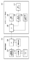
本発明の第1の実施の形態について図面を参照して説明する。図1は、第1実施形態におけるMRシステムの装置構成の全体図である。
<< First Embodiment >>
(Device configuration)
A first embodiment of the present invention will be described with reference to the drawings. FIG. 1 is an overall view of an apparatus configuration of an MR system in the first embodiment.
現実世界と仮想世界をリアルタイムかつシームレスに融合させる技術である複合現実感、いわゆるMR(Mixed Reality)技術では、撮像機能付表示装置(以下、撮像機能付表示装置をHMD(Head Mounted Display)と略す。ただし、双眼鏡のような手持ちタイプの装置でもよく、頭部装着型の装置に限らない)を利用する。本実施形態では、HMD(頭部装着型ディスプレイ)の撮像部により取得した装着者視点の現実空間の背景画像に、装着者の位置、方向などの三次元位置姿勢情報に基づいて生成されたCG画像を重畳し、HMDの表示部で表示する。これにより、HMD装着者はCGで描画されたオブジェクトが、観察している現実空間内にあたかも存在しているかのような複合現実感を体感することができる。 In mixed reality technology, which is a technology that seamlessly fuses the real world and the virtual world in real time, so-called MR (Mixed Reality) technology, a display device with an imaging function (hereinafter, a display device with an imaging function is abbreviated as HMD (Head Mounted Display)). However, a hand-held type device such as binoculars may be used and not limited to a head-mounted type device). In the present embodiment, a CG generated based on the three-dimensional position and orientation information such as the position and direction of the wearer in the background image of the real space of the wearer viewpoint acquired by the imaging unit of the HMD (head-mounted display). The image is superimposed and displayed on the display unit of the HMD. As a result, the HMD wearer can experience a mixed reality as if the object drawn in CG is present in the observed real space.
図1のように、本実施形態におけるMRシステムは、HMD101、コントローラ102、画像処理装置103を備えている。
As shown in FIG. 1, the MR system according to this embodiment includes an
HMD101は、装着者の観察している現実空間の画像を取得する撮像部と、表示画像を装着者に提供する画像表示部を有する。画像表示部が装着者に提供する表示画像には、撮像した現実空間画像や、画像処理装置103からの出力画像、または現実空間画像に画像処理装置103で生成したCG画像を重畳した合成画像などが含まれる。また、HMD101は、コントローラ102と通信を行う機能を有し、コントローラ102からの電源供給を受けて駆動することも、バッテリーで駆動することも可能な構成である。
The
コントローラ102と接続された画像処理装置103は、CG画像の描画を行うCG描画部と、現実空間画像とCG画像を合成する画像合成部を有する。画像処理装置103はコントローラ102を介し、HMD101と通信を行う。HMD101では、合成画像を受信し、HMD101の画像表示部によりこの合成画像をHMD装着者に表示する。コントローラ102は、画像の解像度変換、色空間変換、本実施形態の特徴である光学系の歪み補正等の各種画像処理や、伝送フォーマット変換等の機能を備えている。
The
なお、図1では、画像処理装置103とコントローラ102を別々のハードウェア構成としているが、コントローラ102と画像処理装置103がそれぞれ有する機能を集め、専用の画像処理装置104を構成してもよい。また、図1中では各々の装置は有線の通信回線で接続されているが、これらの一部またはそのすべてを無線の通信回線で接続する形態としてもよい。さらには、コントローラ102の機能の一部または全部をHMD101側に取り込む構成でも構わない。以下の説明では機能的な観点から、コントローラ102とHMD101がそれぞれ有する機能を組み合わせたものをHMD101として説明する。
In FIG. 1, the
(機能構成)
次に本実施形態に係る複合現実システムの機能構成について図2を参照して説明する。図2は、本実施形態におけるビデオシースルー型複合現実システムの機能ブロック図である。
(Functional configuration)
Next, the functional configuration of the mixed reality system according to the present embodiment will be described with reference to FIG. FIG. 2 is a functional block diagram of the video see-through mixed reality system in the present embodiment.
201はビデオシースルー型のHMDである。HMD201は以下の構成を備える。
・外界を撮像する撮像ユニット203。
・CGが重畳されたMR画像を表示する表示ユニット207。
・CGの描画、合成を行う画像処理装置202とのI/F(インターフェース)205。
・HMDの位置姿勢情報を出力する三次元位置姿勢センサ204。
・本実施形態に係る表示系収差補正部206(後述)を有する。
An
A
An I / F (interface) 205 with an
A three-dimensional position and
A display system aberration correction unit 206 (described later) according to the present embodiment is included.
202は画像処理装置であり、HMD201から受け取った撮像画像から位置姿勢情報を生成したり、その位置姿勢情報に基づいてCG画像を生成し、撮像画像と合成したりする。一般にはパソコンやワークステーション等の高性能な演算処理機能やグラフィック表示機能を有する装置を用いて実現可能である。
An
203は、HMD装着者の視線位置と略一致する外界の観察画像を撮像する撮像ユニットである。ステレオ画像を生成するための右目用、左目用の二組の撮像素子と光学系および後段の画像処理を行うための信号処理回路を有する。光学系の構成については後述する。
204は、HMD装着者の位置姿勢情報を得るための三次元位置姿勢センサである。磁気センサやジャイロセンサ(加速度、角速度)が使用される。後述する位置姿勢情報生成部209で必要なセンサ出力の情報を生成するが、撮像画像を解析して位置姿勢情報を検出してもよく、必ずしも搭載が必須となるデバイスではない。
205はI/F(インタフェース)であり、撮像ユニット203で撮像された画像を画像処理装置202に伝送したり、合成されたMR画像をHMD201へ伝送したりする。I/F205は、HMD201と画像処理装置202との間のデータ通信を行う際に、インターフェースとして機能するものであり、画像処理装置202側に設けられているI/F208も同様に機能する。なお、何れのI/F205、208についても、リアルタイム性を有し、かつ大容量の伝送が可能な通信規格を採用することが望ましい。有線系であれば、例えば、USBやIEEE1394のメタル線、GigabitEthernet(登録商標)等の光ファイバを使用することができる。無線系であれば、例えば、IEEE802.11のワイヤレスLAN、IEEE802.15のワイヤレスPAN規格等に準拠した高速無線通信等を使用することができる。本実施形態では有線系であれば光ファイバ、無線系であればUWB(Ultra Wide Band)を想定している。光ファイバの伝送帯域は数Gbps、UWBは数百Mbpsである。将来的には数Gbpsの帯域を持つミリ波による無線通信方式を採用してもよい。
206は、表示光学系で生じる収差を補正する表示系収差補正部である。詳細については後述する。
207は、合成されたMR画像を表示するための表示ユニットである。表示ユニット207は、撮像ユニット203と同じく、右目用、左目用の二組の表示デバイスと光学系を有する。表示デバイスは小型の液晶ディスプレイやMEMS(Micro Electro Mechanical System)による網膜スキャンタイプのデバイスが使用される。光学系の構成については後述する。
208は、画像処理装置側のI/Fである。I/F208の構成はHMD201内のI/F205と同様であるため、説明を省略する。
209は、受け取った画像情報から、HMD装着者の位置姿勢情報を生成する位置姿勢情報生成部である。撮像画像からマーカやマーカの代わりとなる特徴点を抽出して位置姿勢情報を生成する。なお、撮像画像中に使用すべきマーカや特徴点がない場合でも、例えば、不図示の客観視点による撮像画像や、HMD201に取り付けられた三次元位置姿勢センサ204による情報を補足的に使用して位置姿勢を検出してもよい。
A position / orientation
210はCG描画部であり、コンテンツDB211に保持されているそれぞれの仮想物体に係るデータを用いて、それぞれの仮想物体を仮想空間中に配置した仮想空間を形成する。そして、形成した仮想空間において観察者の視点から見える画像(CG画像)を生成する。所定の位置姿勢を有する視点から見える仮想空間の画像を生成する処理の詳細は周知であるので、その説明は省略する。
211は、仮想画像のコンテンツを納めたコンテンツDB(データベース)であり、仮想空間を構成する各仮想物体に係るデータを保持する。仮想物体に係るデータには、例えば、仮想物体の配置位置姿勢や、その動作則を示すデータが含まれる。また、仮想物体がポリゴンでもって構成されている場合には、各ポリゴンの法線ベクトルデータやその色データ、ポリゴンを構成している各頂点の座標位置データ等も含まれる。また、仮想物体にテクスチャマッピングを施す場合には、テクスチャデータも含まれる。 A content DB (database) 211 stores virtual image content, and holds data related to each virtual object constituting the virtual space. The data related to the virtual object includes, for example, data indicating the placement position and orientation of the virtual object and its operation rule. When the virtual object is composed of polygons, normal vector data of each polygon, its color data, coordinate position data of each vertex constituting the polygon, and the like are also included. In addition, when texture mapping is performed on a virtual object, texture data is also included.
212は、背景画像として描画された撮像画像と、CG画像とを合成するMR画像合成部である。ここで得られたMR画像は、I/F208を介してHMD201に送られて、表示に使用される。
An MR
上記構成を用いた処理の流れは以下の通りである。すなわち、撮像ユニット203で得られた撮像画像が、I/F206を介して画像処理装置202へ送信される。そして、画像処理装置202において、受け取った撮像画像中の識別マーカやその他の特徴量に基づき、HMD201の位置姿勢情報が算出される。その後、撮像画像を背景画像として、前述した位置姿勢情報に基づいて生成されたCG画像が重畳され、合成画像であるMR画像が生成される。合成されたMR画像は、I/F208を介してHMD201へ送られる。HMD201では、撮像系と同様に表示光学系の収差を表示系収差補正部206で補正して、表示ユニット207で表示する。以上の構成および処理のプロセスにより、収差が補正された表示画像であるMR画像を得るとともに、好ましい画像を使用者の瞳に導くことが可能となる。
The flow of processing using the above configuration is as follows. That is, the captured image obtained by the
(画像処理装置のハードウェア構成)
図3は、画像処理装置に適用可能なコンピュータのハードウェア構成を示すブロック図である。
(Hardware configuration of image processing device)
FIG. 3 is a block diagram illustrating a hardware configuration of a computer applicable to the image processing apparatus.
301はCPUであり、RAM302やROM303に格納されているプログラムやデータを用いて、コンピュータ全体の制御を行うと共に、本コンピュータを適用した画像処理装置202が行う処理を実行する。
302はRAM(書き込み可能メモリ)である。RAM302は、外部記憶装置306からロードされたプログラムやデータ、I/F307を介して外部(本実施形態の場合、HMD201)から受信したデータ等を一時的に記憶するためのエリアを有する。また、CPU301が各種の処理を実行する際に用いるワークエリアも有する。RAM302は、各種のエリアを適宜提供することができる。
303はROM(読み出し専用メモリ)であり、本コンピュータの設定データやブートプログラム等を格納する。304は操作部であり、キーボードやマウスなどにより構成されている。本コンピュータの操作者は操作部304を操作することで、CPU301に対して各種の指示を入力することができる。
305は表示部であり、CRTや液晶画面等により構成されている。表示部305は、CPU301や不図示のグラフィックスボードによる処理結果を画像や文字でもって操作者へ表示することができる。
A
306は外部記憶装置であり、ハードディスクドライブ装置に代表される大容量情報記憶装置で実現することができる。ここにはOS(オペレーティングシステム)や、画像処理装置202が行う後述各処理をCPU301に実行させるためのプログラムやデータが保存されている。これらのプログラムやデータは、CPU301による制御に従って、適宜、RAM302にロードされ、CPU301による処理の対象となる。
307はI/Fであり、図2に示したI/F208に相当する。I/F307は、HMD201とのデータ通信を行うためのインターフェースとして機能する。308は上述の各部を繋ぐバスである。
尚、以上の各装置と同等の機能を実現するソフトウェアにより、ハードウェア装置の代替として構成することもできる。 In addition, it can also be comprised as an alternative of a hardware apparatus with the software which implement | achieves a function equivalent to the above each apparatus.
また、本実施形態では、説明の便宜のため、コンピュータを1つの装置で実現した構成について述べるが、複数の装置にリソースを分散した構成によって実現してもよい。例えば、記憶や演算のリソースを複数の装置に分散した形に構成してもよい。或いは、コンピュータ上で仮想的に実現される構成要素毎にリソースを分散し、並列処理を行うようにしてもよい。 In this embodiment, for convenience of explanation, a configuration in which a computer is realized by a single device is described. However, a configuration in which resources are distributed to a plurality of devices may be realized. For example, storage and calculation resources may be distributed in a plurality of devices. Alternatively, resources may be distributed for each component virtually realized on the computer, and parallel processing may be performed.
(HMDのハードウェア構成)
図4は、HMDのハードウェア構成を示すブロック図である。401は撮像ユニット203に相当するものであり、402は表示ユニット207に相当するものである。403はRAMで、CPU406が各種の処理を行うために用いるワークエリアや、I/F205を介して外部(ここでは画像処理装置202)から受信したデータを一時的に記憶するためのエリア等を有する。
(HMD hardware configuration)
FIG. 4 is a block diagram illustrating a hardware configuration of the HMD. 401 corresponds to the
404はROMで、HMD201が行う後述の各処理をCPU406に実行させるためのプログラムやデータが格納されている。405は三次元位置センサ204に相当するものである。406はCPUで、HMD201の初期設定を始め、各種デバイスの制御を行うプログラムを実行する。407はI/Fで、図2に示したI/F205に相当するものである。409は上述の各部を繋ぐバスである。
408は収差補正LSIで、表示系収差補正部206に相当するものである。ここでは専用集積回路であるASICを想定しているが、信号処理プロセッサであるDSPによってソフト的に機能を記述し実現する構成でもよい。処理内容の詳細については後述する。
(収差)
次に、光学系に起因する収差について図5を参照して説明する。図5は、歪曲収差並びに倍率色収差を説明する図である。図5において、図5(a)は歪曲のない状態、図5(b)は歪曲した状態、図5(c)は歪曲収差に加えて倍率色収差の生じた状態を示している。
(aberration)
Next, aberration caused by the optical system will be described with reference to FIG. FIG. 5 is a diagram for explaining distortion and lateral chromatic aberration. 5, FIG. 5 (a) shows a state without distortion, FIG. 5 (b) shows a state of distortion, and FIG. 5 (c) shows a state in which lateral chromatic aberration occurs in addition to distortion.
実レンズを用いて結像させると、図5(a)のような図形を撮像した場合は、図5(b)のように画像が歪んでしまう。このように、表示画像が単色か否かに関わらず、レンズの形状に起因して生じる画像の歪みを歪曲収差と呼ぶ。 When an image is formed using a real lens, the image is distorted as shown in FIG. 5B when a figure as shown in FIG. Thus, regardless of whether the display image is monochromatic or not, image distortion caused by the shape of the lens is referred to as distortion.
一方、光線はその波長によって屈折率が異なり、画像の拡大倍率は原色毎に相違するため、表示デバイス上で色によって結像位置(倍率)が異なる現象が生じる。このように色によって画像の拡大倍率が異なるために生じる光学収差を倍率色収差と呼ぶ。 On the other hand, since the refractive index of a light beam varies depending on its wavelength and the magnification of an image differs for each primary color, a phenomenon occurs in which the image formation position (magnification) varies depending on the color on the display device. The optical aberration that occurs because the magnification of the image differs depending on the color is referred to as lateral chromatic aberration.
図5(c)は倍率色収差が生じる様子を模式的に示している。図5(c)では、RGB三原色の内、Greenを実線で、Redを破線で、Blueを一点鎖線で表している。ここで、Red、Green、Blueの光線はそれぞれ波長が異なるため、各色の光線によってレンズでの屈折率も異なる。したがって、図5(c)のように、Greenの像に対して、Redの像は外側に、Blueの像は内側に結ぶことになる。このため、例えば、白黒の被写体については、その像のエッジに色にじみ(色ずれ)が生じる。また、カラー画像の被写体については、境界領域等の色味が変わるエッジ部分では同様の色にじみが生じてしまう。 FIG. 5C schematically shows how chromatic aberration of magnification occurs. In FIG. 5C, among the three primary colors of RGB, Green is represented by a solid line, Red is represented by a broken line, and Blue is represented by a one-dot chain line. Here, since the red, green, and blue light beams have different wavelengths, the refractive index of the lens varies depending on the light beams of each color. Therefore, as shown in FIG. 5C, the Red image is connected to the outside and the Blue image is connected to the inside of the Green image. For this reason, for example, for a monochrome subject, color blurring (color shift) occurs at the edge of the image. For a color image subject, the same color blur occurs at the edge portion where the color changes such as the boundary region.
(表示光学系)
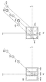
次に、表示光学系について図6を参照して説明する。図6は、表示光学系の一例を示す図である。
(Display optical system)
Next, the display optical system will be described with reference to FIG. FIG. 6 is a diagram illustrating an example of the display optical system.
601は、表示パネルである。後述する画素構成を有するTFT液晶や有機ELのデバイスであり、TFT液晶の場合は不図示のバックライトを光源とした光を各色のフィルタを経由して照射する構成となる。有機ELデバイスの場合は自発光であるためバックライトは不要である。使用者に提示するカラー画像をこのパネル上に形成する。
602は、小型の表示パネル601からの光線を拡大し瞳に導くための自由曲面プリズムである。単なるレンズと比べて薄型、小型化を実現することが可能である。
603は、表示パネル601で形成した画像の結像点である。この位置に瞳を持ってくることで、表示パネル601の画像が拡大された大画面の表示画像を見ることができる。
一般に光学系で生じる各種収差は複数のレンズ群よってその影響を抑えるが、小型のHMDの実現には光学系の簡略化、小型・軽量化が欠かせない。そのため倍率色収差以外の収差の影響を極力抑え、倍率色収差を電子的に補正する協調システムの設計が有用である。 In general, various aberrations generated in an optical system are suppressed by a plurality of lens groups, but simplification of the optical system and reduction in size and weight are indispensable for realizing a small HMD. Therefore, it is useful to design a cooperative system that suppresses the influence of aberrations other than lateral chromatic aberration as much as possible and electronically corrects lateral chromatic aberration.
(表示デバイスの構成)
図7は、表示デバイスの画素構成を示す模式図である。図7は、図6に示す表示パネル601の一部を拡大した正面図を模式的に示している。
(Display device configuration)
FIG. 7 is a schematic diagram illustrating a pixel configuration of the display device. FIG. 7 schematically shows an enlarged front view of a part of the
701は、後述する複数色(本実施形態では3色)のフィルタを有する画素である。ここでは、画素701は、RGBの各色情報をもとに階調表現を行う物理的な単位として機能する。
702a、702b、702cは、一つの画素701に含まれる原色光を発する原色エレメントとしての色フィルタであり、それぞれR(赤)、G(緑)、B(青)の色を持つ。図7に示されるように各画素701内のフィルタ構成は同一であり、図7の例では水平方向にはRGBの各色が繰り返し規則的に配置されている。各フィルタ間の距離(それぞれのフィルタ中央位置の間隔)は、各画素が正方で一辺の長さを3dとすれば、それぞれdとなる。
702a, 702b, and 702c are color filters as primary color elements that emit primary color light included in one
ここではRGBの三原色を有する画素の構成例を説明したが、画素を構成する色の組み合わせはRGBに限定されない。また、補色のフィルタ構成やRGBに追加する形で3色よりも多い色による構成や、あるいは、RGBよりも色数が少ない(例えば、一色減らした2色)による構成としてもよい。また、本実施形態では、原色光を発する原色エレメントを色フィルタで実現する例を説明するが、色フィルタ以外のデバイスを用いて原色エレメントを実現してもよい。 Here, the configuration example of the pixel having the three primary colors of RGB has been described, but the combination of the colors configuring the pixel is not limited to RGB. Further, a complementary color filter configuration, a configuration with more than three colors added to RGB, or a configuration with fewer colors than RGB (for example, two colors reduced by one color) may be used. In this embodiment, an example in which primary color elements that emit primary color light are realized by color filters will be described. However, primary color elements may be realized by using devices other than color filters.
(表示系収差補正部)
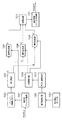
図8は、上述の表示系収差補正部206の機能構成を示すブロック図である。
(Display aberration correction unit)
FIG. 8 is a block diagram showing a functional configuration of the display system
801は前処理部である。収差補正自体の処理は変形を伴う解像度変換処理とみなすことができるため、一部ではほとんどサイズの変わらない縮小処理となる場合もある。前処理部801は、折り返し歪みの影響を低減するための高調波成分を除去する処理をローパスフィルタによって実行する。
802は、RGBの色成分を持つ画素を有する画像データを格納するバッファである。
A
803は色分離部であり、バッファ802から所望の座標(アドレス)の画素の値を読み出し、RGBの色成分に分離する。入力が輝度と色差信号の場合は、画素を各色成分に構成し直す処理を前処理として行う。
A
804は収差補正テーブルである。収差補正テーブル804は、参照点の座標に対応する変換後の座標値を算出するための値を格納する。本実施形態では、この変換後の座標値を算出するために、基点の考え方を採用している。テーブル構成および格納する値の詳細については後述する。
805は、各色の補正値を選択する補正値選択部である。表示する画素の参照点を決定し、参照点が変換される座標を参照テーブルである収差補正テーブル804から読み出す。補正値選択部では、参照点の座標と対応する変換座標を算出するための補正値を読み出す。
806は座標算出部であり、補正値選択部805で選択された補正値をもとに、各色の変換後の座標を演算する。収差補正テーブル804は、容量削減のため特定色については変換後の座標を格納し、特定色を除く他色についてはこの特定色を基準とした差分を格納している。座標算出部806では、この他色の変換後の座標を基準色の座標と差分値から算出する。
A coordinate
807、808および809は補間処理部であり、変換後の座標と基となる画素のそれぞれの色の値をもとに補間位置におけるそれぞれの新たな色の値を算出する。補間処理部807はGreen(緑)、補間処理部808はRed(赤)、補間処理部809はBlue(青)の各色の新たな値を算出する。補間位置は実際に表示パネル上の画素の位置である。
810は色結合部であり、補間処理部807〜809でそれぞれ求められた補間位置における新たな色の値をもとに、表示画素における色情報を結合する。例えば各色8ビットの入力データが存在する場合、変換後の画素の結合で各色8ビットの入力に対して、合計24ビットの画素データとして出力する。
811は後処理部である。フィルタによる強調処理や色味の補正などの各種画像処理を実行する。
(位置ズレ量算出の原理)
次に、位置ズレ量を算出する処理の原理について図9を参照して説明する。図9は、位置ズレ量算出の際の基点位置を示す原理図である。
(Principle of positional deviation calculation)
Next, the principle of the processing for calculating the positional deviation amount will be described with reference to FIG. FIG. 9 is a principle diagram showing the base point position when calculating the positional deviation amount.
図9(a)は、従来の位置ズレ量算出の原理を示している。図9(a)の例でも、画素901は、R(赤)902a、G(緑)902b、B(青)902cを有している。図9(a)では、画素901における発光の基点位置は画素の中央位置としている。RGB三原色の混じった白色W903を発光の基点として、光学系の収差の影響によってずれて表示される位置をそれぞれ、Rを904、Gを905、Bを906としている。従来の構成では、図9(a)のように、画素の位置をG902bの位置で近似して、W903、R904、G905、B906が一直線上に配置されるモデルで色ズレを想定していた。言い換えると、G902bの位置を基点としてR、G、Bが同一方向にずれるモデルで色ズレを近似していた。そして、従来は、このW903と、R904、G905、B906とのズレ量を補正値として参照テーブルに格納していた。
このズレ量は、基点位置903に対する、R904、G905、B906の相対位置を示す量であり、例えば、水平方向及び/又は垂直方向の座標間距離、または、2点間の距離で示すことができる。
FIG. 9A shows the principle of conventional positional deviation amount calculation. Also in the example of FIG. 9A, the
This amount of deviation is an amount indicating the relative position of R904, G905, and B906 with respect to the
なお、ここでは基点W903で発光させた場合のズレが生じる位置を904〜906としているが、これは904〜906の位置で各色を発光させた場合に各色が目に到達する際の位置をW903ということもできる。実際には、G色の変換後の位置905と基点903との差分をG色の補正値とすることによって、テーブルに格納するパラメータのビット数を削減していた。R904やB906については、G905との差分値を格納することで、テーブルに格納すべき情報量をさらに削減していた。
Here, the positions where deviation occurs when light is emitted at the base point W903 are 904 to 906, but this is the position when each color reaches the eyes when light is emitted at the
これに対して、本実施形態では、原色エレメントが発する原色光の各々について、発光源となる原色エレメントの位置を基準とした位置ずれ量を取得して、表示画像の各画素の表示デバイスにおける表示位置を原色成分ごとに算出する。そして、その表示位置に表示画像の画素を表示するように表示制御する。このため、本実施形態の構成によれば、各画素内で各原色を発するエレメントが別個に設けられている表示デバイスにおいても、光学収差を適切に補正することができる。したがって、例えばHMDのように、表示デバイスがユーザの瞳に近接して使用される状況においても、画素内の色ズレを低減することができる。 In contrast, in the present embodiment, for each of the primary color light emitted from the primary color elements, a positional shift amount based on the position of the primary color element serving as the light emission source is acquired, and the display device displays each pixel of the display image. The position is calculated for each primary color component. Then, display control is performed so that pixels of the display image are displayed at the display position. For this reason, according to the configuration of the present embodiment, the optical aberration can be appropriately corrected even in a display device in which an element emitting each primary color is separately provided in each pixel. Therefore, even in a situation where the display device is used close to the user's pupil, such as an HMD, color misregistration within the pixel can be reduced.
図9(b)は、本実施形態における位置ズレ算出の原理を示した図である。図9(b)のように、本実施形態では発光の基点を画素の中央ではなく、各色の中央としている点が従来と相違する。すなわち、Rの基点は従来の基点であるW903より左(X軸負方向)へ1/3画素分ずれたRの発光位置907aとなる。同様に、Bの基点は従来の基点であるW903より右(X軸正方向)へ1/3画素分ずれたBの発光位置907cとなる。その結果、変換後の各色の位置は、Rについては、従来の変換位置904から908へ移動する。同様に、Bについては、従来の変換位置906から909へずれることになる。実際にはこのズレた分が画質への影響を与えることになるため、図9(b)のように基点を設定することで補正画像をさらに高画質化することができる。
FIG. 9B is a diagram illustrating the principle of positional deviation calculation in the present embodiment. As shown in FIG. 9B, the present embodiment is different from the prior art in that the base point of light emission is not the center of the pixel but the center of each color. That is, the R base point is the
(収差補正テーブル)
次に、収差補正テーブル804(単に、補正テーブルともいう)について、図10A、図10Bを参照して説明する。図10Aは、収差補正テーブルに格納する補正値を求める原理を示す図であり、図10Bは、収差補正テーブルの例を示す図である。
(Aberration correction table)
Next, the aberration correction table 804 (also simply referred to as a correction table) will be described with reference to FIGS. 10A and 10B. FIG. 10A is a diagram illustrating a principle for obtaining a correction value stored in the aberration correction table, and FIG. 10B is a diagram illustrating an example of the aberration correction table.
収差補正テーブル804には、図10Bに示すように変換前座標である参照位置のアドレスと変換後の座標(アドレス)の差分値が組として格納されている。参照するアドレスで所望の画素のX−Y座標を指定することによって、基準色(本実施形態ではG)は変換後の座標を、基準色以外の他色(RとB)については基準色との差分値(テーブル格納値)を得ることができる。図10Aのように、Rの座標は、格納されているGとの差分値1001(Gx−Rx)とGの変換後のX座標Gxから、Bの座標は、格納されているGの差分値1002(Bx−Gx)と同じくGのX座標Gxからそれぞれ求めることができる。 In the aberration correction table 804, as shown in FIG. 10B, the difference value between the address of the reference position, which is the coordinates before conversion, and the coordinate (address) after conversion is stored as a set. By specifying the XY coordinates of a desired pixel at the address to be referred to, the reference color (G in the present embodiment) is converted into coordinates, and the colors other than the reference color (R and B) are set as the reference color. The difference value (table stored value) can be obtained. As shown in FIG. 10A, the R coordinate is the difference value 1001 (Gx−Rx) from the stored G and the X coordinate Gx after the conversion of G, and the B coordinate is the difference value of the stored G. Similarly to 1002 (Bx−Gx), it can be obtained from the X coordinate Gx of G.
このように、本実施形態では、表示デバイスの各画素において予め定められた基準原色エレメントについて、当該基準原色エレメントが発する原色光の位置ずれ量を基準位置ずれ量として取得する。そして、画素に含まれる基準原色エレメント以外の原色エレメントの各々について、当該原色エレメントの前記基準原色エレメントに対する相対位置と、前記基準位置ずれ量とに基づいて、位置ずれ量を取得する。このため、本実施形態の構成によれば、表示デバイスに含まれる全ての原色エレメントについてそれぞれ別個に位置ずれ量を取得するよりも、簡易な処理で位置ずれ量を取得することができる。 As described above, in the present embodiment, for the reference primary color element determined in advance in each pixel of the display device, the position shift amount of the primary color light emitted from the reference primary color element is acquired as the reference position shift amount. For each primary color element other than the reference primary color element included in the pixel, a positional deviation amount is acquired based on the relative position of the primary color element with respect to the reference primary color element and the reference positional deviation amount. For this reason, according to the configuration of the present embodiment, it is possible to acquire the positional deviation amount by a simple process, rather than acquiring the positional deviation amounts individually for all the primary color elements included in the display device.
また、本実施形態では、この基準位置ずれ量をあらかじめ収差補正テーブル804として、外部記憶装置306等の記憶装置に記憶しておき、当該記憶装置を読み出して基準位置ずれ量を取得する。このため、必要なときは、収差補正テーブル804を参照することで、容易に基準位置ずれ量を取得することができる。
In this embodiment, the reference positional deviation amount is stored in advance in a storage device such as the
図10Bのように、本実施形態では変換前の座標もテーブルに記憶するが、変換前の座標をメモリアクセス時のアドレスと対応づけてもよい。この場合、変換前座標をメモリ領域にとる必要がなくなり、メモリサイズをさらに削減することが可能である。 As shown in FIG. 10B, the coordinates before conversion are also stored in the table in this embodiment, but the coordinates before conversion may be associated with the address at the time of memory access. In this case, it is not necessary to take the coordinates before conversion in the memory area, and the memory size can be further reduced.
(座標変換処理)
次に、表示系収差補正部206が実行する座標変換処理について、図11を参照して説明する。図11は、座標変換処理の流れを示すフローチャートである。本実施形態では、処理対象の画像の全ての画素に対して、それぞれステップS1101〜S1103の処理を実行する。
(Coordinate conversion process)
Next, a coordinate conversion process executed by the display system
まず、ステップS1101では、処理対象の画像中の参照画素の座標を指定する。この座標の指定は上記のようにアドレスを指定して行ってもよい。 First, in step S1101, the coordinates of the reference pixel in the processing target image are designated. The coordinates may be specified by specifying an address as described above.
次に、ステップS1102では、参照点の変換後のアドレス得るために収差補正テーブル804から、この参照点に対応する補正値を取得する。 In step S1102, a correction value corresponding to this reference point is acquired from the aberration correction table 804 in order to obtain an address after conversion of the reference point.
次に、ステップS1103では、ステップS1102で得られた収差補正テーブル804に格納されている値、すなわち各色の変換後の座標を算出するための色ズレ量をもとに、参照画素におけるそれぞれの色の変換後の座標を算出する。具体的には、補正前の各色の座標値に対して、ステップS1102で取得した補正値を加算して変換座標を算出する。例えば、収差補正テーブル804が図10Bで示される場合、処理対象の画素の変換前座標が(xn,yn)ときは、補正後のGの座標は(Gxn,Gyn)となる。そして、Rの座標は(Gxn,Gyn)からRのテーブル値を減算したもの、Bの座標は(Gxn,Gyn)にBのテーブル値を加算したものとなる。 Next, in step S1103, based on the value stored in the aberration correction table 804 obtained in step S1102, that is, the amount of color misregistration for calculating the coordinates after conversion of each color, each color in the reference pixel is determined. Calculate the coordinates after conversion. Specifically, the converted coordinate is calculated by adding the correction value acquired in step S1102 to the coordinate value of each color before correction. For example, when the aberration correction table 804 is shown in FIG. 10B, when the pre-conversion coordinates of the pixel to be processed are (xn, yn), the corrected G coordinates are (Gxn, Gyn). The R coordinate is obtained by subtracting the R table value from (Gxn, Gyn), and the B coordinate is obtained by adding the B table value to (Gxn, Gyn).
ステップS1104では、処理対象となる全画素に対して上記座標変換処理を実行したかどうかを判断する。全画素に対して処理が終了している場合は座標変換処理を終了する。終了していない場合はステップS1101に戻って対応する画素の収差を補正するための座標変換演算を繰り返し実行する。 In step S1104, it is determined whether the coordinate conversion process has been executed on all pixels to be processed. If the process has been completed for all pixels, the coordinate conversion process is terminated. If not completed, the process returns to step S1101 to repeatedly execute the coordinate conversion calculation for correcting the aberration of the corresponding pixel.
以上のように、本実施形態では、光学系による歪曲収差と色収差を信号処理によって補正する際に、色ズレ量を規定するための基点位置を画素の位置ではなく、原色光ごとに、画素を構成する各原色エレメントの位置としている。このため、座標変換における位置ズレの精度を高くし、結果、高画質化を図ることが可能となる。 As described above, in this embodiment, when correcting distortion and chromatic aberration due to the optical system by signal processing, the base point position for defining the amount of color misregistration is not the pixel position but the pixel for each primary color light. The position of each primary color element to be configured is used. For this reason, it is possible to increase the accuracy of the positional deviation in the coordinate conversion, and as a result, to improve the image quality.
特に、このような画像処理を行う構成を頭部装着型ディスプレイ(HMD)が備えることで、表示デバイスがユーザの瞳に近接して画角が大きい場合でも、偽色や色にじみなどを低減することができる。 In particular, a head-mounted display (HMD) having such a configuration for image processing reduces false colors and color blur even when the display device is close to the user's pupil and has a large angle of view. be able to.
<<第2実施形態>>
本発明の第2の実施の形態を図に従って説明する。第1実施形態では色ズレ量を規定するための基点を画素の中央から、画素を構成する各色の中央へと移すことによって座標変換による位置ズレ補正の精度を高めていた。これに対して、本実施形態では、従来の構成と同様に画素の中央を基点としながら、第1実施形態と同等の変換精度を維持しつつ、さらに補正テーブルサイズの削減を実現する構成を説明する。
<< Second Embodiment >>
A second embodiment of the present invention will be described with reference to the drawings. In the first embodiment, the accuracy of positional deviation correction by coordinate conversion is increased by moving the base point for defining the amount of color deviation from the center of the pixel to the center of each color constituting the pixel. In contrast, in the present embodiment, a configuration that further reduces the correction table size while maintaining the same conversion accuracy as in the first embodiment while using the center of the pixel as a base point as in the conventional configuration will be described. To do.
(表示系収差補正部)
図12は、第2実施形態における表示系収差補正部206のブロック図である。本実施形態では、第1実施形態で参照した図8の構成に加えて色ズレ量算出部1212を備えていることが第1実施形態の構成と異なる。第1実施形態の図8と同様の構成、同様の機能のブロック(1201〜1211)については説明を省略する。本実施形態でも第1実施形態同様に、表示光学系を対象とし、表示パネルの画素は複数の色を有する。
(Display aberration correction unit)
FIG. 12 is a block diagram of the display system
1212は、色ズレ量算出部である。本実施形態では、収差補正テーブル1204に格納されている補正値は光学系を対称系とみなすことでサイズを削減したものが保持されており、色ズレ量算出部1212はこの補正値を非対称系に適用する処理を実行する。なお、対称系とは、本実施形態では、回転対称系、光学系をその中心を軸として任意の角度で回転させても、光学収差等は同様に発生することを意味する。この場合、この光学系は垂直軸にも水平軸にも対称であることは言うまでもない。処理の原理、収差補正テーブルの構成および処理フローについては後述する。
(位置ズレ量算出の原理)
図13A、図13Bは、色ズレ量の補正処理の原理を示す模式図である。図13Aは、光学原点Oとパネル上の画素P1とP2との関係を示している。ここで、光学系は光学原点Oを通る垂直軸(y)に対して対称である。P1とP2はy軸に対して対称な画素であり、光学原点Oからx軸方向への距離x1とx2は等しい関係にある。そして、y軸方向への距離はy1で共通である。
(Principle of positional deviation calculation)
13A and 13B are schematic diagrams illustrating the principle of color misregistration correction processing. FIG. 13A shows the relationship between the optical origin O and the pixels P1 and P2 on the panel. Here, the optical system is symmetric with respect to a vertical axis (y) passing through the optical origin O. P1 and P2 are symmetric pixels with respect to the y-axis, and the distances x1 and x2 from the optical origin O in the x-axis direction have the same relationship. The distance in the y-axis direction is common to y1.
一般に画素構成が軸に対して対称となる場合および対称とみなしても問題のない場合は、y軸に対して右半分または左半分の参照用のテーブルを持ち、折り返して反対側へも適用することができる。しかし、HMDのような拡大光学系においては、一般的に、表示デバイスとユーザの瞳との距離が近接していることから、表示画角が比較的大きく、したがって、表示デバイスの画素数が十分でないことが多い。例えば、画素数が1920×1080の表示デバイスを用いても、色ズレが目立ってしまう場合がある。このため、信号処理による画像補正、すなわちアドレス変換による収差補正処理によって、ユーザが色のズレを認識できないようにするには、画素を構成する色フィルタの並びを考慮した補正値の生成と格納が必要となる。なお、本実施形態でも第1実施形態で参照した図7のように、画素内の色フィルタが左から順にR、G、Bと並んでいるものとする。 In general, when the pixel configuration is symmetric with respect to the axis and when there is no problem even if it is considered to be symmetric, a table for reference on the right half or the left half with respect to the y axis is provided and folded and applied to the opposite side. be able to. However, in a magnifying optical system such as an HMD, since the distance between the display device and the user's pupil is generally close, the display angle of view is relatively large, and therefore the number of pixels of the display device is sufficient. Often not. For example, even when a display device having a pixel number of 1920 × 1080 is used, color misalignment may be noticeable. For this reason, in order to prevent the user from recognizing color misregistration by image correction by signal processing, that is, aberration correction processing by address conversion, generation and storage of correction values in consideration of the arrangement of color filters constituting pixels is required. Necessary. In this embodiment as well, as shown in FIG. 7 referred to in the first embodiment, it is assumed that the color filters in the pixels are arranged in the order of R, G, and B from the left.
そこで、本実施形態では、表示光学系がその中心を基準に対称となる形状を有している場合、収差補正テーブル804は、表示デバイスの基準となる象限に含まれる各画素について基準位置ずれ量を記憶しておく。そして、基準となる象限に含まれない画素に含まれる基準原色エレメントの各々について、該画素が含まれる象限の基準となる象限に対する相対位置と、基準となる象限の該画素に対応する画素の基準位置ずれ量と、に基づいて、位置ずれ量を取得する。また、基準となる象限に含まれない画素に含まれる基準原色エレメント以外の原色エレメントの各々については、これらの情報に加えて、該原色エレメントの前記基準原色エレメントに対する相対位置に基づいて、位置ずれ量を取得する。このように、表示光学系の形状が対称であることを利用することで、収差補正テーブル804に記憶すべきデータ量を削減することができる。 Therefore, in the present embodiment, when the display optical system has a shape that is symmetric with respect to the center thereof, the aberration correction table 804 includes the reference positional deviation amount for each pixel included in the quadrant serving as the reference of the display device. Remember. Then, for each reference primary color element included in a pixel not included in the reference quadrant, the relative position of the quadrant including the pixel with respect to the reference quadrant, and the pixel reference corresponding to the pixel in the reference quadrant The positional deviation amount is acquired based on the positional deviation amount. Further, for each primary color element other than the reference primary color element included in the pixel not included in the reference quadrant, in addition to the above information, the positional shift is based on the relative position of the primary color element with respect to the reference primary color element. Get the quantity. Thus, by utilizing the fact that the shape of the display optical system is symmetric, the amount of data to be stored in the aberration correction table 804 can be reduced.
図13Bは、図13Aで説明した構成において、色の並びを考慮したのと同程度の座標変換精度を実現するための原理を示す模式図である。P1は光学原点Oを通る軸に対して右半分に位置する。第1実施形態では、RとBについては各色の中心を基点としたズレ量を規定していた。その場合は光学的にはy軸について対称であってもP2で示されるように画素内の色の並びが左右で対称とならないため画面内のすべての画素について補正値を持つ必要がある。 FIG. 13B is a schematic diagram illustrating the principle for realizing the coordinate conversion accuracy equivalent to that in consideration of the color arrangement in the configuration described in FIG. 13A. P1 is located on the right half with respect to the axis passing through the optical origin O. In the first embodiment, for R and B, the amount of deviation with respect to the center of each color is defined. In this case, even if optically symmetric with respect to the y-axis, as shown by P2, the color arrangement in the pixels is not symmetric with respect to the left and right, so it is necessary to have correction values for all the pixels in the screen.
これに対して、本実施形態では近似的に、基点Rからのズレが生じた位置をR”とする。R”は画素の中央であるGを基点とする一般的な収差補正の手法によって変換されるR位置から画素を構成する色間の距離であるdx分だけ、GからみたR方向(x軸に対して左方向)へシフトした値となる。同様にB”はBからdx分だけGから見てB方向(x軸に対して右方向)へシフトした値となる。本来の変換後の位置はRであればRの位置を基点としたものである必要があるが、RとGの距離dxが、光学原点OからのRの距離に対して十分に小さいため、誤差は無視し得る。光学原点からのRの距離が近い領域(画像中央部)ではRと光学原点との距離は小さくなるが、ズレ量自体も相対的に小さくなるため、誤差は無視しうる。なお、P2についても同様の考えを適用するが、対称軸(y軸)に対して左側にあるため、色によってシフトする方向が異なることに留意する。 On the other hand, in this embodiment, the position where the deviation from the base point R occurs is approximately R ″. R ″ is converted by a general aberration correction method using G which is the center of the pixel as the base point. The value is shifted in the R direction viewed from G (leftward with respect to the x axis) by dx, which is the distance between colors constituting the pixel from the R position. Similarly, B ″ is a value shifted from B by dx in the B direction (rightward with respect to the x axis) as viewed from G. If the original converted position is R, the position of R is used as a base point. However, since the distance dx between R and G is sufficiently small relative to the distance R from the optical origin O, the error can be ignored. In the middle part), the distance between R and the optical origin is small, but the error is negligible because the amount of deviation is relatively small, and the same idea applies to P2, but the symmetry axis (y Note that the shift direction differs depending on the color because it is on the left side of the axis.
このように一般的な画素中央を基点とする補正値を持つ参照テーブルであっても、画素内の色の並びを考慮した変換座標位置の修正を適宜行うことで、高画質化と同時にメモリ容量を削減することができる。 In this way, even for a reference table having a correction value based on the center of a general pixel, by appropriately correcting the conversion coordinate position in consideration of the arrangement of colors in the pixel, the memory capacity can be improved simultaneously with high image quality. Can be reduced.
(収差補正テーブル)
次に、本実施形態における収差補正テーブル804(単に、補正テーブルともいう)について、図14A、図14Bを参照して説明する。図14Aは、収差補正テーブルに格納する補正値を求める原理を示す図であり、図14Bは、収差補正テーブルの例を示す図である。
(Aberration correction table)
Next, an aberration correction table 804 (also simply referred to as a correction table) in the present embodiment will be described with reference to FIGS. 14A and 14B. FIG. 14A is a diagram illustrating a principle for obtaining a correction value stored in the aberration correction table, and FIG. 14B is a diagram illustrating an example of the aberration correction table.
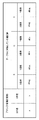
図14(a)は、収差補正テーブルに格納する各色の値がどこを基点とした差分として構成されているかを示した模式図である。画素の中央であるG色を基点に変換後のRGB各色のx方向のズレ量はそれぞれ、RがdGx−dRxg、GがdGx、BがdGx+dBxgとなる。つまり、ここでは、RとBについては基準色であるGからの差分をさらにとることで容量を削減している。これは表現する距離が短くなることで、必要となるビット数が減るからである。y方向のズレ量についても同様にそれぞれ、RがdGy−dRyg、GがdGy、BがdGy+dBygとなる。なお、最終的なズレ量の算出にはこの値の他、画素を構成する色間の距離dxを使用する。 FIG. 14A is a schematic diagram showing where each color value stored in the aberration correction table is configured as a difference. The shift amounts in the x direction of the RGB colors after conversion from the G color at the center of the pixel as the base point are R for dGx−dRxg, G for dGx, and B for dGx + dBxg, respectively. That is, here, for R and B, the capacity is reduced by further taking the difference from G which is the reference color. This is because the number of bits required decreases as the distance expressed becomes shorter. Similarly, regarding the amount of misalignment in the y direction, R is dGy−dRyg, G is dGy, and B is dGy + dByg. Note that, in addition to this value, the distance dx between colors constituting the pixel is used for calculation of the final deviation amount.
図14(b)は、参照テーブルに格納している値である。ズレ量自体は上記で示している通りであるが、RとBについては基準色であるG色の座標または基点であるWから変換後のG色との間のズレ量であるdGx、dGyをベースにその差分だけを格納している。このため、あとは加算および減算処理によってズレ量およびそれを元にした変換後の座標を算出することができる。その結果、Rには差分値であるdRxgとdRygを、Bにも同様に差分値であるdBxgとdBygを格納する。 FIG. 14B shows values stored in the reference table. The deviation amount itself is as described above, but for R and B, the GG coordinates that are the reference colors or the deviation amounts between the base point W and the converted G color are dGx and dGy. Only the difference is stored in the base. For this reason, the shift amount and the coordinate after conversion based on it can be calculated by addition and subtraction processing. As a result, the difference values dRxg and dRyg are stored in R, and the difference values dBxg and dByg are similarly stored in B.
本実施形態では変換前の座標についてもテーブルに格納するが、第1実施形態と同様に、変換前の座標をメモリアクセスのアドレスと対応づけることによって、変換前座標をメモリ領域にとる必要がないようにしてもよい。 In this embodiment, the coordinates before conversion are also stored in the table. However, as in the first embodiment, the coordinates before conversion need not be stored in the memory area by associating the coordinates before conversion with the memory access address. You may do it.
(色ズレ量算出処理)
図15は、色ズレ量算出処理の流れを示すフローチャートである。第1実施形態の図11と同様の処理内容については説明を省略する。本実施形態では、補正値を取得した後、図13を参照して説明した処理原理に従い色ズレの値を調整する点が第1実施形態と異なる。
(Color misregistration calculation processing)
FIG. 15 is a flowchart illustrating the flow of color misregistration amount calculation processing. The description of the same processing contents as those in FIG. 11 of the first embodiment will be omitted. This embodiment is different from the first embodiment in that after obtaining the correction value, the value of the color misregistration is adjusted according to the processing principle described with reference to FIG.
ステップS1501とステップS1502までの処理は、図11のステップS1101とS1102の処理と同様のため説明は省略する。 The processing up to step S1501 and step S1502 is the same as the processing of steps S1101 and S1102 in FIG.
ステップS1503では、参照テーブルから取得した補正値をもとに色ズレの量を調整する。Rのズレ量は取得した補正値(dRxg、dRyg)を用いて、以下の演算式で算出する。
・x方向のズレ量=dGx−dRxg−dx(dxは色間の距離)。
・y方向のズレ量=dGy−dRyg。
同様にBのズレ量は以下の演算式で算出することができる。
・x方向のズレ量=dGx+dBxg+dx(dxは色間の距離)。
・y方向のズレ量=dGy+dByg。
In step S1503, the amount of color misregistration is adjusted based on the correction value acquired from the reference table. The deviation amount of R is calculated by the following arithmetic expression using the acquired correction values (dRxg, dRyg).
The amount of deviation in the x direction = dGx−dRxg−dx (dx is the distance between colors).
The amount of deviation in the y direction = dGy−dRyg.
Similarly, the deviation amount of B can be calculated by the following arithmetic expression.
X-direction misalignment = dGx + dBxg + dx (dx is the distance between colors).
The amount of deviation in the y direction = dGy + dByg.
なお、dRxg、dRyg、dBxg、dBygおよびdGx、dGyは絶対値で値を持つとすると、光学原点Oを座標原点とした場合y軸に対して右側は上式になるが、左側は第二項であるdRxgおよびdBxgの符号が反対となる。なお、この色ズレ量の調整は変換後の座標算出と一緒に処理を行っても構わない。 Assuming that dRxg, dRyg, dBxg, dByg and dGx, dGy have absolute values, when the optical origin O is the coordinate origin, the right side of the y-axis is the above equation, but the left side is the second term. The signs of dRxg and dBxg are opposite. The adjustment of the color misregistration amount may be performed together with the coordinate calculation after conversion.
次に、ステップS1504では、参照点の変換後の座標を算出する。具体的にはステップS1503で得た各色のズレ量を画素の基点の座標である参照点の変換前の座標に加減算することになる。 Next, in step S1504, coordinates after conversion of the reference point are calculated. Specifically, the shift amount of each color obtained in step S1503 is added to or subtracted from the coordinates before conversion of the reference point, which is the coordinates of the base point of the pixel.
ステップS1505の処理も図11のステップS1104と同様であるため、説明を省略する。 The processing in step S1505 is also the same as that in step S1104 in FIG.
以上説明してきたように、本実施形態によれば画素の並びが非対称であっても対称系の参照テーブルを利用することで、座標の変換精度を維持しつつテーブルを構成するメモリ容量の削減と回路規模の低減および処理の高速化を実現することが可能となる。なお、メモリ容量の削減は、チップ点数や基板面積の削減に寄与しコストダウンを実現すると共に、参照テーブルへのアクセス回数を減らすことにもなる。その結果、処理の高速化、消費電力の低減を実現することも可能となる。 As described above, according to the present embodiment, even if the arrangement of pixels is asymmetrical, by using a symmetric reference table, the memory capacity of the table can be reduced while maintaining the conversion accuracy of coordinates. It is possible to reduce the circuit scale and increase the processing speed. Note that the reduction in memory capacity contributes to the reduction in the number of chips and the substrate area, thereby realizing cost reduction and reducing the number of accesses to the reference table. As a result, it is possible to realize high speed processing and low power consumption.
<<第3実施形態>>
本発明の第3の実施の形態について図面を参照して説明する。第1および第2実施形態では変換後の画素である参照画素の座標を調整していた。本実施形態では、参照画素の元情報自体の調整と、最終的な補間位置のアドレスの、各色の表示位置に合わせた修正との、少なくともいずれかを実行する。これにより、画素が複数の色によって構成されていることの影響を考慮した座標変換および補間処理を行う。
<< Third Embodiment >>
A third embodiment of the present invention will be described with reference to the drawings. In the first and second embodiments, the coordinates of reference pixels that are converted pixels are adjusted. In the present embodiment, at least one of adjustment of the original information of the reference pixel itself and correction of the address of the final interpolation position according to the display position of each color is executed. As a result, coordinate conversion and interpolation processing are performed in consideration of the influence of the pixel being composed of a plurality of colors.
(基準座標補正の原理)
図16は、参照画素の基準座標補正の原理を示す模式図である。図16(a)は、画素を構成する各色フィルタの内、Rに注目して参照位置を修正する原理を示す模式図である。表示デバイスの解像度が画角に対して十分高い場合は、画素は点を表しているとみなすことができ、各画素は色によらず点の中で各色の値を持っているとみなすことができる。しかし、HMDにおいては、各画素が分離し得ないほど解像化が高くなく、画角に対して解像度が低いことが一般的である。このため、本実施形態では、表示デバイスの解像度が低いことを前提に、各色の位置に合わせて参照画素の色の値を修正する。
(Basic coordinate correction principle)
FIG. 16 is a schematic diagram illustrating the principle of reference coordinate correction of a reference pixel. FIG. 16A is a schematic diagram showing the principle of correcting the reference position by paying attention to R among the color filters constituting the pixel. If the resolution of the display device is high enough for the angle of view, the pixel can be considered to represent a point, and each pixel can be considered to have a value for each color in the point, regardless of color. it can. However, in the HMD, the resolution is not so high that each pixel cannot be separated, and the resolution is generally low with respect to the angle of view. For this reason, in this embodiment, on the assumption that the resolution of the display device is low, the color value of the reference pixel is corrected in accordance with the position of each color.
具体的には、算出した表示画像の画素の表示位置の周囲に位置する、表示デバイスの各画素に含まれる原色エレメントの出力を調整して、表示画像の各画素の表示を補間する。これにより、画角に対して解像度が低い構成でも表示画像の品質を高めることができる。 Specifically, the output of the primary color element included in each pixel of the display device located around the display position of the calculated pixel of the display image is adjusted, and the display of each pixel of the display image is interpolated. As a result, the quality of the display image can be improved even in a configuration with a low resolution relative to the angle of view.
図16(a)において、Rに関して光学収差の補正を行う場合、補正の基点となる参照点の位置は、表示デバイス全体が巨視的に観察される場合、すなわち、解像度が画角に対して十分高い場合は、Gである画素の中央位置と同視できる。一方、表示デバイスの各画素が詳細に観察可能な場合、すなわち、解像度が画角に対して低い場合は、補正の基点となる参照位置はRの色があるR’の中央位置となる。 In FIG. 16A, when optical aberration correction is performed with respect to R, the position of the reference point serving as the correction base point is when the entire display device is macroscopically observed, that is, the resolution is sufficient with respect to the angle of view. If it is high, it can be equated with the center position of the pixel being G. On the other hand, when each pixel of the display device can be observed in detail, that is, when the resolution is lower than the angle of view, the reference position serving as the correction base point is the center position of R ′ where the R color is present.
なお、座標変換後の表示点の位置が表示デバイスの画素の中央点の位置に一致しない場合は、その表示点の周囲の画素で補間して表示点を表現する。したがって、本実施形態では、周りの画素の値をもとに新たにRの色の値を算出することになる。なお、補間手法は、線形の補間手法を使用しても、高次の補間手法を使用しても構わない。 If the position of the display point after coordinate conversion does not match the position of the center point of the pixel of the display device, the display point is expressed by interpolation with pixels around the display point. Therefore, in this embodiment, a new R color value is calculated based on the values of surrounding pixels. The interpolation method may be a linear interpolation method or a higher-order interpolation method.
図16(b)は、補間処理の原理を示す模式図である。補間処理は通常画素の中央位置を補間位置として考えるが、ここでは各色フィルタの位置で補間位置を修正する。図16(b)ではRに注目して、補間位置が左側へシフトしている。 FIG. 16B is a schematic diagram showing the principle of the interpolation process. In the interpolation process, the center position of the normal pixel is considered as the interpolation position. Here, the interpolation position is corrected at the position of each color filter. In FIG. 16B, paying attention to R, the interpolation position is shifted to the left.
まず、一般的な補間処理について説明する。二次元の座標系における表示中心座標O(x0,y0)を原点とするレンズの収差情報および解像度情報より、二次元座標系における各画素の各々の位置における収差量を求める。そして、この収差量だけ補正するためのx軸方向、y軸方向の各々の座標変換量を画素毎に求める。 First, general interpolation processing will be described. The aberration amount at each position of each pixel in the two-dimensional coordinate system is obtained from the aberration information and resolution information of the lens with the display center coordinate O (x0, y0) in the two-dimensional coordinate system as the origin. Then, coordinate conversion amounts in the x-axis direction and the y-axis direction for correcting only this aberration amount are obtained for each pixel.
そして、求めた座標変換量だけ各画素の各色を座標変換したときの、二次元座標系における各画素位置(本来の画素位置)における画像データ(RGBの各値)を補間演算により求めるための補正パラメータを求める。 Then, correction for obtaining image data (each RGB value) at each pixel position (original pixel position) in the two-dimensional coordinate system when each color of each pixel is coordinate-transformed by the obtained coordinate transformation amount. Find the parameters.
補間位置の修正を行わない、すなわち色によらず補間位置を画素の中央とする場合には、図16(b)のように、画素P1の画像データ(x1,y1)を、座標変換後にこの画素P1の周囲の4個の画素P1’、P2’、P3’、P4’の値に基づいて求める。具体的には、P1’、P2’、P3’、P4’の座標をP1’(x1’,y1’)、P2’(x2’,y2’)、P3’(x3’,y3’)、P4’(x4’,y4’)とすると、以下の式に従って補間演算により求められる。 When correction of the interpolation position is not performed, that is, when the interpolation position is set to the center of the pixel regardless of the color, the image data (x1, y1) of the pixel P1 is converted to this after the coordinate conversion as shown in FIG. It is determined based on the values of the four pixels P1 ′, P2 ′, P3 ′, and P4 ′ around the pixel P1. Specifically, the coordinates of P1 ′, P2 ′, P3 ′, and P4 ′ are P1 ′ (x1 ′, y1 ′), P2 ′ (x2 ′, y2 ′), P3 ′ (x3 ′, y3 ′), and P4. If '(x4', y4 '), it is obtained by interpolation calculation according to the following equation.
P1(x1,y1)=P1’・(1−px)(1−py)+P2’・px(1−py)
+P3’・(1−px)py+P4’・px・py。
なお、pxおよびpyは、座標変換前の画像データが表す画素の位置と、座標変換後の画像データが表す画素の位置との偏差を表している。ここで、
px=(x1−x1’)/(x2’−x1’)
py=(y1−y3’)/(y1’−y3’)
が成り立つ。
P1 (x1, y1) = P1 ′ · (1−px) (1−py) + P2 ′ · px (1−py)
+ P3 ′ · (1−px) py + P4 ′ · px · py.
Px and py represent the deviation between the position of the pixel represented by the image data before coordinate conversion and the position of the pixel represented by the image data after coordinate conversion. here,
px = (x1−x1 ′) / (x2′−x1 ′)
py = (y1−y3 ′) / (y1′−y3 ′)
Holds.
本実施形態では、補正パラメータとして、上式に従って変換するためのデータ、すなわち上式による画像データP1(x1,y1)への変換において、画像データを参照すべき画素のアドレスを表すデータx、yおよび定数px、pyを求める。なお、x、yは変換後の座標をそれぞれ表している。上式に従って各画素の画像データを変換することは、実質的に、歪曲収差の方向と逆の方向に画像が歪むように画像データを補正することに相当する。 In the present embodiment, as the correction parameter, data x, y representing the address of a pixel to which image data should be referred in the conversion to the image data P1 (x1, y1) according to the above equation as data for conversion according to the above equation. And constants px and py are obtained. Note that x and y represent the coordinates after conversion. Converting the image data of each pixel according to the above equation substantially corresponds to correcting the image data so that the image is distorted in a direction opposite to the direction of distortion.
画素の中央位置と色の位置が一致するG色については上記が当てはまるが、補間位置の修正を行う場合には、画素内の色の並びに応じた補間位置のシフトが必要である。すなわち、R色であれば左方向に色間の距離dx分シフトしたPr(xr1,y1)が補間位置となる。ここで、xr1=x1−dxである。 The above is true for the G color whose color position matches the center position of the pixel. However, when correcting the interpolation position, it is necessary to shift the interpolation position according to the arrangement of the colors in the pixel. That is, in the case of the R color, Pr (xr1, y1) shifted by the distance dx between the colors in the left direction becomes the interpolation position. Here, xr1 = x1-dx.
なお、ここでは上式に示される線形の補間処理を実行する場合を説明したが、Bicubicに代表される三次式による補間処理や、NearestNeighbor等の最近傍近似による補間アルゴリズムを採用してもよい。 Although the case where the linear interpolation process shown in the above equation is executed has been described here, an interpolation process using a cubic equation represented by Bicubic or an interpolation algorithm using nearest neighbor approximation such as NearestNeighbor may be adopted.
図16(c)は、画素を構成する各色の内、Bに注目して参照位置を修正する原理を示す模式図である。図16(d)は、B色における補間処理の原理を示す模式図である。B色についての補間処理もR色についての補間処理と同様に行うことができる。 FIG. 16C is a schematic diagram illustrating the principle of correcting the reference position by paying attention to B among the colors constituting the pixel. FIG. 16D is a schematic diagram illustrating the principle of interpolation processing for B color. The interpolation process for the B color can be performed in the same manner as the interpolation process for the R color.
(補間処理)
図17は、補間処理の流れを示すフローチャートである。ステップS1701では、補間位置の修正を行うか否かを判定する。修正を行う場合(ステップS1701でYES)はステップS1702へ進み、行わない場合(ステップS1701でNO)はステップS1703へ進む。
(Interpolation process)
FIG. 17 is a flowchart showing the flow of interpolation processing. In step S1701, it is determined whether to correct the interpolation position. If correction is to be performed (YES in step S1701), the process proceeds to step S1702. If not (NO in step S1701), the process proceeds to step S1703.
ステップS1702では、補間位置の修正処理を行う。補間位置の修正は図16(b)を参照して説明した手法に基づいて実行することができる。R色については、画素の中心を基準として求められる補間位置を、左方向に画素内の色間距離であるdx分だけずらした位置を補間位置とする。G色についてはシフト処理は行わない。B色については、画素の中心を基準として求められる補間位置を、Rと逆方向である右方向にずらした位置を補間位置とする。 In step S1702, interpolation position correction processing is performed. The correction of the interpolation position can be executed based on the method described with reference to FIG. For the R color, the interpolation position obtained by shifting the interpolation position obtained with reference to the center of the pixel by dx which is the inter-color distance in the pixel in the left direction is set as the interpolation position. Shift processing is not performed for G color. For the B color, the interpolation position obtained by shifting the interpolation position obtained with reference to the center of the pixel to the right, which is the opposite direction to R, is set as the interpolation position.
ステップS1703では、参照画素の再構成を行うか否かを判断する。参照画素の再構成、すなわち色によっては参照する位置を修正する処理を選択する場合(ステップS1703でYES)はステップS1704へ進み、選択しない場合(ステップS1703でNO)はステップS1705へ進む。 In step S1703, it is determined whether to reconstruct the reference pixel. If the reconstruction of the reference pixel, that is, the process for correcting the reference position depending on the color is selected (YES in step S1703), the process proceeds to step S1704, and if not selected (NO in step S1703), the process proceeds to step S1705.
ステップS1704では、参照位置を修正する。参照位置の修正は図16(a)を参照して説明した手法に基づいて実行することができる。実際には色によって参照位置をずらした新たな参照画素の値を補間処理によって再構成するのではなく、補間処理時に参照する参照画素の座標を色によってずらすことで対応する。そうすることで比較的簡単な処理で参照点の画像の再構成を実現することができる。なお、ステップS1702の補間位置の修正処理およびステップS1704の参照位置の修正処理はどちらを先に処理しても構わない。 In step S1704, the reference position is corrected. The correction of the reference position can be executed based on the method described with reference to FIG. Actually, instead of reconstructing the value of a new reference pixel whose reference position is shifted by color by interpolation processing, the coordinates of the reference pixel to be referred to at the time of interpolation processing are shifted by color. By doing so, the reference point image can be reconstructed with relatively simple processing. Note that either the interpolation position correction process in step S1702 or the reference position correction process in step S1704 may be performed first.
ステップS1705では、各色の補間位置における色の値を算出する。これまでに算出してきた参照画素の座標、すなわち変換後の座標と、新たな画素を生成する補間位置における補間処理を実行する。 In step S1705, the color value at the interpolation position of each color is calculated. Interpolation processing is executed at the reference pixel coordinates calculated so far, that is, the coordinates after conversion, and the interpolation position for generating a new pixel.
ステップS1706では、処理対象となる全画素に対して上記補間処理を実行したかどうかを判断する。全画素に対して処理が終了している場合は補間処理を終了する。終了していない場合は先頭に戻って補間処理を実行する。 In step S1706, it is determined whether the interpolation processing has been executed for all pixels to be processed. If the process has been completed for all pixels, the interpolation process is terminated. If not completed, return to the beginning and execute the interpolation process.
以上説明してきたように、本実施形態によれば表示画素の構成に合わせて、元画像の再構成、すなわち、参照画素の位置修正と、表示位置に合わせた補間位置の修正との少なくともいずれかを行う。このため、低解像度の表示構成時には画質の改善を図ることが可能となる。同じ画素数、画像サイズの表示パネルを使用した場合において、広画角化を実現するHMDでは特に有効である。 As described above, according to the present embodiment, according to the configuration of the display pixel, the original image is reconstructed, that is, at least one of the correction of the position of the reference pixel and the correction of the interpolation position according to the display position. I do. For this reason, it is possible to improve the image quality when the display configuration is low resolution. This is particularly effective in an HMD that realizes a wide angle of view when a display panel having the same number of pixels and image size is used.
<<第4実施形態>>
第1および第2の実施形態では変換座標の算出をテーブル参照型のアドレス変換によって行っていたが、本実施形態では近似多項式を利用して位置ずれ量を取得して原色光ごとに変換座標を算出する。このため、収差補正テーブル804を記憶する記憶装置を設けなくても、光学収差を適切に補正して画質の高い画像を表示することができる。
<< Fourth Embodiment >>
In the first and second embodiments, the conversion coordinates are calculated by table reference type address conversion. However, in this embodiment, an approximate polynomial is used to obtain a positional deviation amount, and the conversion coordinates are obtained for each primary color light. calculate. For this reason, even if a storage device for storing the aberration correction table 804 is not provided, it is possible to appropriately correct the optical aberration and display a high-quality image.
テーブル参照型のアドレス変換による座標変換以外に、近似多項式を使用した座標変換方式が知られている。一般に撮像光学系の場合、理想像高xに対する実像高yをxの三次関数である三次曲線で示すことができる。表示光学系では自由曲面プリズム等複雑な光学系を用いた場合、近似式との差違の絶対値を抑える場合には10次程度の高い次数が必要となる場合がある。そこで、近似多項式と係数パラメータを用いて変換後の座標群を算出する。 In addition to coordinate conversion by table reference type address conversion, a coordinate conversion method using an approximate polynomial is known. In general, in the case of an imaging optical system, the real image height y with respect to the ideal image height x can be represented by a cubic curve that is a cubic function of x. When a complicated optical system such as a free-form surface prism is used in the display optical system, a higher order of about 10th order may be required to suppress the absolute value of the difference from the approximate expression. Therefore, a coordinate group after conversion is calculated using the approximate polynomial and coefficient parameters.
第2実施形態と同様に、左右が非対称系であっても対称系の近似多項式を適用することが可能である。すなわち対称軸に対するズレ分を考慮して係数パラメータを微修正する構成をとる。その結果、表示パネルの左右で微妙に異なる位置ズレ量を考慮した近似多項式を準備するのではなく、軸に対して片側の近似多項式を用意し、パラメータの調整によって両側に適用することができる。 Similar to the second embodiment, an approximate polynomial of a symmetric system can be applied even if the left and right are asymmetrical systems. That is, the coefficient parameter is finely corrected in consideration of the deviation with respect to the symmetry axis. As a result, instead of preparing an approximation polynomial that takes into account slightly different positional deviation amounts on the left and right of the display panel, an approximation polynomial on one side with respect to the axis can be prepared and applied to both sides by adjusting parameters.
近似多項式の利用をRGB各色に適用するとテーブル参照型と比べて大幅な回路規模の増大につながる。ここでは、回路規模とテーブルサイズのバランスを重視している。論理演算回路規模に余裕があり、外付けメモリの増設が難しい場合には特に有効である。上記の手法を適用するとパラメータ格納のためのメモリ容量を削減することができる。また、同等の回路の使い回しや近似領域が半減するため同じ精度を維持しても次数を下げられる可能性もある。 Applying the use of approximate polynomial to each RGB color leads to a significant increase in circuit scale compared to the table reference type. Here, emphasis is placed on the balance between the circuit scale and the table size. This is particularly effective when there is a margin in the logical operation circuit scale and it is difficult to add an external memory. When the above method is applied, the memory capacity for parameter storage can be reduced. In addition, since the number of times of using equivalent circuits and the approximate area are halved, the order may be reduced even if the same accuracy is maintained.
<<その他の実施形態>>
座標演算自体に補間演算を適用することで、収差補正テーブル804が記憶すべきデータ量を更に削減することができる。例えば、例えば8画素おきにサンプリングした場合には、トータルでテーブルのサイズを1/64に低減することが可能となる。補間演算の精度と、補間演算を行う回路規模とはトレードオフの関係があるが、用途や目的に応じて、回路規模をある程度にまで抑えて、メモリ容量を削減することができる。
<< Other Embodiments >>
By applying the interpolation calculation to the coordinate calculation itself, the amount of data to be stored in the aberration correction table 804 can be further reduced. For example, when sampling is performed every 8 pixels, for example, the total table size can be reduced to 1/64. Although there is a trade-off relationship between the accuracy of the interpolation calculation and the circuit scale for performing the interpolation calculation, the memory capacity can be reduced by suppressing the circuit scale to a certain degree according to the application and purpose.
また、上記実施形態では、画素の構成がx軸方向に周期的な色並びである例について説明したが、これらがy軸方向であっても構わない。また軸を表示パネルに対して水平、垂直方向に設定しているが、光学系の構成、表示パネルの構成および装置としての配置によってはその軸が斜め方向になることもあり、その際にも本実施形態で説明してきた構成が適用できることは言うまでもない。 In the above-described embodiment, an example in which the pixel configuration is a periodic color arrangement in the x-axis direction has been described, but these may be in the y-axis direction. The axis is set horizontally and vertically with respect to the display panel. Depending on the configuration of the optical system, the configuration of the display panel, and the arrangement of the device, the axis may be inclined. It goes without saying that the configuration described in this embodiment can be applied.
また、上記実施形態では、表示パネルを構成する画素の色がRGBの三原色の場合の例を説明したが、この色に限定されない。ただし、色が異なる場合は、その色に合わせて、適宜、色変換等の前処理を行ってもよい。 Moreover, although the said embodiment demonstrated the example in case the color of the pixel which comprises a display panel is three primary colors of RGB, it is not limited to this color. However, if the colors are different, preprocessing such as color conversion may be appropriately performed according to the colors.
また、上記実施形態では、収差補正の適用対称が、接眼の拡大光学系を採用するHMDである場合を中心に説明した。しかし、上記実施形態の適用対称はHMDに限定されない。例えば、デジタル一眼カメラやデジタルビデオカメラ等に搭載されるEVFを対象としても同様の効果が得られることは言うまでもない。 Further, in the above-described embodiment, the case where the application symmetry of aberration correction is an HMD that employs an eyepiece magnification optical system has been mainly described. However, the application symmetry of the above embodiment is not limited to the HMD. For example, it goes without saying that the same effect can be obtained for EVFs mounted on digital single-lens cameras, digital video cameras, and the like.
また、上記実施形態で説明してきた構成をお互いに組み合わせて使用できることは説明するまでもない。 Needless to say, the configurations described in the above embodiments can be used in combination with each other.
さらには、上記各実施形態における様々な技術を適宜組み合わせて新たなシステムを構成することは当業者であれば容易に相当し得るものである。したがって、このような様々な組み合わせによるシステムもまた、本発明の技術的範囲に含まれうる。 Furthermore, it is easy for those skilled in the art to configure a new system by appropriately combining various techniques in the above embodiments. Therefore, the system by such various combinations can also be included in the technical scope of the present invention.
また、本発明の目的は、コンピュータプログラムやコンピュータプログラムを格納したコンピュータ読み取り可能な記録媒体によっても実現可能である。例えば、次のようにすることによっても本発明の目的は達成される。すなわち、前述した実施形態の機能を実現するソフトウェアのプログラムコードを記録した記録媒体(または記憶媒体)を、システムあるいは装置に供給する。そして、そのシステムあるいは装置のコンピュータ(またはCPUやMPU)が記録媒体に格納されたプログラムコードを読み出し実行する。この場合、記録媒体から読み出されたプログラムコード自体が前述の機能を実現することになり、そのプログラムコードを記録した記録媒体は本発明の技術的範囲に含まれる。 The object of the present invention can also be realized by a computer program or a computer-readable recording medium storing the computer program. For example, the object of the present invention can also be achieved by the following. That is, a recording medium (or storage medium) in which a program code of software that realizes the functions of the above-described embodiments is recorded is supplied to the system or apparatus. Then, the computer (or CPU or MPU) of the system or apparatus reads and executes the program code stored in the recording medium. In this case, the program code itself read from the recording medium realizes the above-described function, and the recording medium on which the program code is recorded is included in the technical scope of the present invention.
また、コンピュータが読み出したプログラムコードを実行することにより、そのプログラムコードの指示に基づき、コンピュータ上で稼働しているオペレーティングシステム(OS)などが実際の処理の一部または全部を行う。その処理によって前述した実施形態の機能が実現される場合も本発明の技術的範囲に含まれることは言うまでもない。 Further, by executing the program code read by the computer, an operating system (OS) or the like running on the computer performs part or all of the actual processing based on the instruction of the program code. It goes without saying that the case where the functions of the above-described embodiments are realized by the processing is also included in the technical scope of the present invention.
さらに、記録媒体から読み出されたプログラムコードが、コンピュータに挿入された機能拡張カードやコンピュータに接続された機能拡張ユニットに備わるメモリに書込まれたとする。その後、そのプログラムコードの指示に基づき、その機能拡張カードや機能拡張ユニットに備わるCPUなどが実際の処理の一部または全部を行い、その処理によって前述した実施形態の各機能が実現される場合も、本発明の技術的範囲に含まれる。 Furthermore, it is assumed that the program code read from the recording medium is written in a memory provided in a function expansion card inserted into the computer or a function expansion unit connected to the computer. Thereafter, the CPU of the function expansion card or function expansion unit performs part or all of the actual processing based on the instruction of the program code, and the functions of the above-described embodiments may be realized by the processing. Are included in the technical scope of the present invention.
なお、本発明を上記記録媒体に適用する場合、その記録媒体には、先に説明したフローチャートで示される処理を実行するプログラムコードが格納されることになる。 When the present invention is applied to the recording medium, the recording medium stores program code for executing the processing shown in the flowchart described above.
Claims (9)
表示手段の画素において予め定められた基準原色エレメントについて、当該基準原色エレメントが発する原色光の位置ずれ量を基準位置ずれ量として取得する第1の取得手段と、
前記画素に含まれる基準原色エレメント以外の原色エレメントについて、当該原色エレメントの前記基準原色エレメントに対する相対位置と、前記基準位置ずれ量とに基づいて、位置ずれ量を取得する第2の取得手段と、
前記取得した位置ずれ量に基づいて、表示画像の画素の前記表示手段における表示位置を原色成分ごとに導出する導出手段と、
表示画像の画素の原色成分を、前記表示手段の、前記導出手段が導出した前記表示位置に表示させる表示制御手段と、
を備えることを特徴とする画像処理装置。 An image processing apparatus for correcting chromatic aberration occurring in the table示光science system,
The predetermined reference primaries element in the pixel of Viewing means, a first acquisition means for acquiring the positional displacement amount of the primary light corresponding reference primaries element emits as the reference position deviation amount,
Second acquisition means for acquiring a positional deviation amount for primary color elements other than the primary primary color element included in the pixel based on a relative position of the primary color element with respect to the reference primary color element and the reference positional deviation amount;
Based on the obtained position deviation amount, and the electrically detecting means for exiting guide the display position on the display unit of the field element of the display image for each primary color component,
An original color components of the picture elements of the display image, said display means, display control means for displaying on the display position where the guide detection means has issued guide,
An image processing apparatus comprising:
前記第1の取得手段は前記記憶手段に記憶された前記基準位置ずれ量を読みだして取得する
ことを特徴とする請求項1に記載の画像処理装置。 And further comprising storage means for storing the reference position deviation amount,
The image processing apparatus according to claim 1 , wherein the first acquisition unit reads and acquires the reference positional deviation amount stored in the storage unit.
前記記憶手段は、前記表示手段の基準となる象限に含まれる画素について前記基準位置ずれ量を記憶し、
前記第2の取得手段は、
前記基準となる象限に含まれない画素に含まれる基準原色エレメントについて、該画素が含まれる象限の前記基準となる象限に対する相対位置と、前記基準となる象限の該画素に対応する画素の基準位置ずれ量と、に基づいて、位置ずれ量を取得し、
前記基準となる象限に含まれない画素に含まれる基準原色エレメント以外の原色エレメントについて、該画素が含まれる象限の前記基準となる象限に対する相対位置と、該原色エレメントの前記基準原色エレメントに対する相対位置と、前記基準となる象限の該画素に対応する画素の基準位置ずれ量と、に基づいて、位置ずれ量を取得する
ことを特徴とする請求項2に記載の画像処理装置。 When the display optical system has a shape that is symmetric with respect to its center,
The storage means may store the reference position deviation amount for picture element included in the quadrant to be a reference of the display means,
The second acquisition means includes
For reference primary color elementary preparative included in the pixel that is not included in the quadrant to be the reference, and the relative position with respect to the quadrant comprising the reference quadrant that includes the pixel, the reference pixel corresponding to the pixel of the quadrant comprising the reference Based on the positional deviation amount, the positional deviation amount is acquired,
For primary element in the non-standard primary elements included in the pixels which are not included in the quadrant to be the reference, and the relative position with respect to the quadrant comprising the reference quadrant that includes the pixel, relative to said reference primary color element of raw color element The image processing apparatus according to claim 2 , wherein a position shift amount is acquired based on a position and a reference position shift amount of a pixel corresponding to the pixel in the reference quadrant.
ことを特徴とする請求項1から3のいずれか1項に記載の画像処理装置。 The display control means is located around the display position in which the guide detection means has issued guide, by adjusting the output of the primary color elements included in the picture element of said display means, interpolating display of picture elements of the display image the image processing apparatus according to any one of claims 1 3, characterized by.
ことを特徴とする請求項1に記載の画像処理装置。 The image processing apparatus according to claim 1, wherein the first acquisition unit acquires the positional deviation amount using an approximate polynomial corresponding to a shape of the display optical system.
表示手段の画素において予め定められた基準原色エレメントについて、当該基準原色エレメントが発する原色光の位置ずれ量を基準位置ずれ量として取得する第1の取得工程と、
前記画素に含まれる基準原色エレメント以外の原色エレメントについて、当該原色エレメントの前記基準原色エレメントに対する相対位置と、前記基準位置ずれ量とに基づいて、位置ずれ量を取得する第2の取得工程と、
前記取得した位置ずれ量に基づいて、表示画像の画素の前記表示手段における表示位置を原色成分ごとに導出する導出工程と、
表示画像の画素の原色成分を、前記表示手段の、前記導出工程において導出された前記表示位置に表示させる表示制御工程と、
を有することを特徴とする画像処理方法。 An image processing method in an image processing apparatus for correcting chromatic aberration occurring in the table示光science system,
The predetermined reference primaries element in the pixel of Viewing means, a first acquisition step of acquiring the positional deviation amount of the primary light corresponding reference primaries element emits as the reference position deviation amount,
A second acquisition step of acquiring a misregistration amount based on a relative position of the primary color element with respect to the reference primary color element and the reference misregistration amount for primary color elements other than the reference primary color element included in the pixel;
Based on the obtained position deviation amount, and a conductive output step of leaving guide the display position on the display unit of the field element of the display image for each primary color component,
An original color components of the picture elements of the display image, said display means, the display control step of displaying on the display position issued guide in the guide out step,
An image processing method comprising:
Priority Applications (2)
| Application Number | Priority Date | Filing Date | Title |
|---|---|---|---|
| JP2008263056A JP5388534B2 (en) | 2008-10-09 | 2008-10-09 | Image processing apparatus and method, head-mounted display, program, and recording medium |
| US12/559,794 US8456485B2 (en) | 2008-10-09 | 2009-09-15 | Image processing apparatus and method, head mounted display, program, and recording medium |
Applications Claiming Priority (1)
| Application Number | Priority Date | Filing Date | Title |
|---|---|---|---|
| JP2008263056A JP5388534B2 (en) | 2008-10-09 | 2008-10-09 | Image processing apparatus and method, head-mounted display, program, and recording medium |
Publications (2)
| Publication Number | Publication Date |
|---|---|
| JP2010091870A JP2010091870A (en) | 2010-04-22 |
| JP5388534B2 true JP5388534B2 (en) | 2014-01-15 |
Family
ID=42098455
Family Applications (1)
| Application Number | Title | Priority Date | Filing Date |
|---|---|---|---|
| JP2008263056A Active JP5388534B2 (en) | 2008-10-09 | 2008-10-09 | Image processing apparatus and method, head-mounted display, program, and recording medium |
Country Status (2)
| Country | Link |
|---|---|
| US (1) | US8456485B2 (en) |
| JP (1) | JP5388534B2 (en) |
Families Citing this family (42)
| Publication number | Priority date | Publication date | Assignee | Title |
|---|---|---|---|---|
| DE102007033486B4 (en) * | 2007-07-18 | 2010-06-17 | Metaio Gmbh | Method and system for mixing a virtual data model with an image generated by a camera or a presentation device |
| US9091851B2 (en) | 2010-02-28 | 2015-07-28 | Microsoft Technology Licensing, Llc | Light control in head mounted displays |
| US10180572B2 (en) | 2010-02-28 | 2019-01-15 | Microsoft Technology Licensing, Llc | AR glasses with event and user action control of external applications |
| US9182596B2 (en) | 2010-02-28 | 2015-11-10 | Microsoft Technology Licensing, Llc | See-through near-eye display glasses with the optical assembly including absorptive polarizers or anti-reflective coatings to reduce stray light |
| US9097890B2 (en) | 2010-02-28 | 2015-08-04 | Microsoft Technology Licensing, Llc | Grating in a light transmissive illumination system for see-through near-eye display glasses |
| CN102906623A (en) | 2010-02-28 | 2013-01-30 | 奥斯特豪特集团有限公司 | Local advertising content on an interactive head-mounted eyepiece |
| US9129295B2 (en) | 2010-02-28 | 2015-09-08 | Microsoft Technology Licensing, Llc | See-through near-eye display glasses with a fast response photochromic film system for quick transition from dark to clear |
| US20150309316A1 (en) | 2011-04-06 | 2015-10-29 | Microsoft Technology Licensing, Llc | Ar glasses with predictive control of external device based on event input |
| US9229227B2 (en) | 2010-02-28 | 2016-01-05 | Microsoft Technology Licensing, Llc | See-through near-eye display glasses with a light transmissive wedge shaped illumination system |
| US9128281B2 (en) | 2010-09-14 | 2015-09-08 | Microsoft Technology Licensing, Llc | Eyepiece with uniformly illuminated reflective display |
| US9759917B2 (en) | 2010-02-28 | 2017-09-12 | Microsoft Technology Licensing, Llc | AR glasses with event and sensor triggered AR eyepiece interface to external devices |
| US9097891B2 (en) | 2010-02-28 | 2015-08-04 | Microsoft Technology Licensing, Llc | See-through near-eye display glasses including an auto-brightness control for the display brightness based on the brightness in the environment |
| US9223134B2 (en) | 2010-02-28 | 2015-12-29 | Microsoft Technology Licensing, Llc | Optical imperfections in a light transmissive illumination system for see-through near-eye display glasses |
| US9134534B2 (en) | 2010-02-28 | 2015-09-15 | Microsoft Technology Licensing, Llc | See-through near-eye display glasses including a modular image source |
| US9341843B2 (en) | 2010-02-28 | 2016-05-17 | Microsoft Technology Licensing, Llc | See-through near-eye display glasses with a small scale image source |
| US20120249797A1 (en) | 2010-02-28 | 2012-10-04 | Osterhout Group, Inc. | Head-worn adaptive display |
| US9285589B2 (en) | 2010-02-28 | 2016-03-15 | Microsoft Technology Licensing, Llc | AR glasses with event and sensor triggered control of AR eyepiece applications |
| US9366862B2 (en) | 2010-02-28 | 2016-06-14 | Microsoft Technology Licensing, Llc | System and method for delivering content to a group of see-through near eye display eyepieces |
| US20120206334A1 (en) * | 2010-02-28 | 2012-08-16 | Osterhout Group, Inc. | Ar glasses with event and user action capture device control of external applications |
| WO2012011893A1 (en) * | 2010-07-20 | 2012-01-26 | Empire Technology Development Llc | Augmented reality proximity sensing |
| US20120062551A1 (en) * | 2010-09-13 | 2012-03-15 | Lg Electronics Inc. | Image display apparatus and method for operating image display apparatus |
| TWI523519B (en) * | 2011-01-28 | 2016-02-21 | 佳能企業股份有限公司 | Image compensation method and system |
| JP5929567B2 (en) * | 2012-07-03 | 2016-06-08 | ソニー株式会社 | Image signal processing apparatus, image signal processing method, and program |
| JP6547622B2 (en) | 2013-04-11 | 2019-07-24 | ソニー株式会社 | Image display device and display device |
| EP2985651B1 (en) | 2013-04-11 | 2020-07-15 | Sony Corporation | Image display device and display device |
| US9595083B1 (en) * | 2013-04-16 | 2017-03-14 | Lockheed Martin Corporation | Method and apparatus for image producing with predictions of future positions |
| US9019405B2 (en) * | 2013-05-21 | 2015-04-28 | Stmicroelectronics, Inc. | Method and apparatus for wavelength specific correction of distortion in digital images |
| US20140347709A1 (en) * | 2013-05-21 | 2014-11-27 | Stmicroelectronics, Inc. | Method and apparatus for forming digital images |
| CN104769935B (en) | 2013-07-16 | 2019-11-19 | 索尼公司 | Display device |
| CN104737060B (en) | 2013-07-16 | 2018-12-11 | 索尼公司 | Display device |
| JP2017026943A (en) * | 2015-07-27 | 2017-02-02 | 株式会社東芝 | Image display device and image processing device |
| US9858637B1 (en) * | 2016-07-29 | 2018-01-02 | Qualcomm Incorporated | Systems and methods for reducing motion-to-photon latency and memory bandwidth in a virtual reality system |
| JP6880174B2 (en) | 2016-08-22 | 2021-06-02 | マジック リープ, インコーポレイテッドMagic Leap,Inc. | Virtual reality, augmented reality, and mixed reality systems and methods |
| US11127110B2 (en) * | 2017-03-01 | 2021-09-21 | Arm Limited | Data processing systems |
| TWI663427B (en) * | 2017-03-15 | 2019-06-21 | 宏碁股份有限公司 | Head mounted display and chroma aberration compensation method using sub-pixel shifting |
| CN107219629B (en) * | 2017-07-14 | 2021-01-08 | 惠州Tcl移动通信有限公司 | Method, storage medium and device for preventing VR device dispersion by RGB superposition |
| GB201713051D0 (en) * | 2017-08-15 | 2017-09-27 | Imagination Tech Ltd | Low latency distortion unit for head mounted displays |
| US10373936B2 (en) * | 2017-08-22 | 2019-08-06 | Facebook Technologies, Llc | Pixel elements including light emitters of variable heights |
| JP6611768B2 (en) * | 2017-08-31 | 2019-11-27 | キヤノン株式会社 | Image display device |
| JP6656213B2 (en) * | 2017-08-31 | 2020-03-04 | キヤノン株式会社 | Image display device |
| US10692420B2 (en) | 2018-09-13 | 2020-06-23 | Arm Limited | Data processing systems |
| JP7261724B2 (en) * | 2019-11-08 | 2023-04-20 | 株式会社日立エルジーデータストレージ | Video display device and video display system |
Family Cites Families (14)
| Publication number | Priority date | Publication date | Assignee | Title |
|---|---|---|---|---|
| JPH0286266A (en) * | 1988-09-21 | 1990-03-27 | Fuji Xerox Co Ltd | Picture reader |
| JPH08205181A (en) | 1995-01-30 | 1996-08-09 | Matsushita Electric Ind Co Ltd | Chromatic aberration correcting circuit and image pickup device with chromatic aberration correcting function |
| JPH09230321A (en) * | 1996-02-20 | 1997-09-05 | Denso Corp | Color liquid crystal display device |
| JP3069073B2 (en) | 1998-01-23 | 2000-07-24 | 三菱電機株式会社 | Telephone equipment |
| JPH11298924A (en) * | 1998-04-14 | 1999-10-29 | Sharp Corp | Head mounted type display device |
| JP4415468B2 (en) * | 2000-01-20 | 2010-02-17 | 株式会社ニコン | Interpolation processing apparatus and recording medium recording interpolation processing program |
| US6857747B2 (en) * | 2001-08-06 | 2005-02-22 | Advanced Digital Optics, Inc. | Color management system |
| JP2004153323A (en) | 2002-10-28 | 2004-05-27 | Nec Micro Systems Ltd | Chromatic aberration correction image processing system |
| US7255448B2 (en) * | 2004-10-20 | 2007-08-14 | Hewlett-Packard Development Company, L.P. | Pixelated color management display |
| JP5116208B2 (en) * | 2004-11-19 | 2013-01-09 | 株式会社ジャパンディスプレイイースト | Image signal display device |
| JP2008116624A (en) * | 2006-11-02 | 2008-05-22 | Ricoh Co Ltd | Projector and method for compensating chromatic difference of magnification |
| JP5251201B2 (en) * | 2008-03-27 | 2013-07-31 | セイコーエプソン株式会社 | Image processing apparatus, image display apparatus, and image processing method |
| JP2010087698A (en) * | 2008-09-30 | 2010-04-15 | Seiko Epson Corp | Optical device and image display device |
| CN103119512A (en) * | 2008-11-02 | 2013-05-22 | 大卫·乔姆 | Near to eye display system and appliance |
-
2008
- 2008-10-09 JP JP2008263056A patent/JP5388534B2/en active Active
-
2009
- 2009-09-15 US US12/559,794 patent/US8456485B2/en active Active
Also Published As
| Publication number | Publication date |
|---|---|
| JP2010091870A (en) | 2010-04-22 |
| US20100091031A1 (en) | 2010-04-15 |
| US8456485B2 (en) | 2013-06-04 |
Similar Documents
| Publication | Publication Date | Title |
|---|---|---|
| JP5388534B2 (en) | Image processing apparatus and method, head-mounted display, program, and recording medium | |
| JP5094430B2 (en) | Image processing method, image processing apparatus, and system | |
| US8373619B2 (en) | Image processing system, image processing apparatus, aberration correction method, and computer-readable storage medium | |
| CN110050250B (en) | Display synchronized image warping | |
| US8836720B2 (en) | Image processing apparatus and image processing method | |
| JP5241698B2 (en) | Image processing apparatus and image processing method | |
| US11960086B2 (en) | Image generation device, head-mounted display, and image generation method | |
| WO2019076348A1 (en) | Virtual reality (vr) interface generation method and apparatus | |
| JP7150134B2 (en) | Head-mounted display and image display method | |
| JP6971590B2 (en) | Image processing equipment, image processing methods and programs | |
| JP7142762B2 (en) | Display device and image display method | |
| JP4889036B2 (en) | Image processing apparatus and image processing method | |
| JP7429515B2 (en) | Image processing device, head-mounted display, and image display method | |
| JP7365184B2 (en) | Image processing device, head-mounted display, and image display method | |
| US10930185B2 (en) | Information processing system, information processing apparatus, output apparatus, program, and recording medium | |
| JP7365185B2 (en) | Image data transmission method, content processing device, head mounted display, relay device, and content processing system | |
| US11106042B2 (en) | Image processing apparatus, head-mounted display, and image displaying method | |
| WO2023140033A1 (en) | Display control device, head-mounted display, and display control method | |
| JP2012118910A (en) | Image processing device, image display system, and image processing program |
Legal Events
| Date | Code | Title | Description |
|---|---|---|---|
| A621 | Written request for application examination |
Free format text: JAPANESE INTERMEDIATE CODE: A621 Effective date: 20111006 |
|
| A977 | Report on retrieval |
Free format text: JAPANESE INTERMEDIATE CODE: A971007 Effective date: 20130327 |
|
| A131 | Notification of reasons for refusal |
Free format text: JAPANESE INTERMEDIATE CODE: A131 Effective date: 20130405 |
|
| A521 | Written amendment |
Free format text: JAPANESE INTERMEDIATE CODE: A523 Effective date: 20130531 |
|
| TRDD | Decision of grant or rejection written | ||
| A01 | Written decision to grant a patent or to grant a registration (utility model) |
Free format text: JAPANESE INTERMEDIATE CODE: A01 Effective date: 20130909 |
|
| A61 | First payment of annual fees (during grant procedure) |
Free format text: JAPANESE INTERMEDIATE CODE: A61 Effective date: 20131008 |
|
| R151 | Written notification of patent or utility model registration |
Ref document number: 5388534 Country of ref document: JP Free format text: JAPANESE INTERMEDIATE CODE: R151 |