JP6708683B2 - Solid fuel gasification system - Google Patents
Solid fuel gasification system Download PDFInfo
- Publication number
- JP6708683B2 JP6708683B2 JP2018050243A JP2018050243A JP6708683B2 JP 6708683 B2 JP6708683 B2 JP 6708683B2 JP 2018050243 A JP2018050243 A JP 2018050243A JP 2018050243 A JP2018050243 A JP 2018050243A JP 6708683 B2 JP6708683 B2 JP 6708683B2
- Authority
- JP
- Japan
- Prior art keywords
- solid fuel
- hopper
- powder
- char
- gasification
- Prior art date
- Legal status (The legal status is an assumption and is not a legal conclusion. Google has not performed a legal analysis and makes no representation as to the accuracy of the status listed.)
- Active
Links
Images


Classifications
-
- C—CHEMISTRY; METALLURGY
- C10—PETROLEUM, GAS OR COKE INDUSTRIES; TECHNICAL GASES CONTAINING CARBON MONOXIDE; FUELS; LUBRICANTS; PEAT
- C10J—PRODUCTION OF PRODUCER GAS, WATER-GAS, SYNTHESIS GAS FROM SOLID CARBONACEOUS MATERIAL, OR MIXTURES CONTAINING THESE GASES; CARBURETTING AIR OR OTHER GASES
- C10J3/00—Production of combustible gases containing carbon monoxide from solid carbonaceous fuels
- C10J3/46—Gasification of granular or pulverulent flues in suspension
Description
本発明は、固体燃料をガス化するガス化システムに関する。 The present invention relates to a gasification system for gasifying a solid fuel.
石炭は、埋蔵量が豊富であり、かつ世界中で産出することから、今後も重要なエネルギー源の一つである。現在、単位重量あたりの発熱量が高い無煙炭や瀝青炭が主に用いられているが、今後は埋蔵量の約半分を占める亜瀝青炭や褐炭の利用を促進する必要がある。瀝青炭や無煙炭と比較すると、亜瀝青炭や褐炭は、水分の含有量が多く、かつ無水ベースでの単位重量あたりの発熱量が低い。特に褐炭は30〜70wt%程度と非常に多くの水分を含み、乾燥した褐炭は自然発火しやすい特徴を有する。このため褐炭は、輸送と保管に多くのコストがかかるため、産炭地周辺で利用されるにとどまっている。 Coal is one of the important energy sources in the future because it has abundant reserves and is produced all over the world. Currently, anthracite and bituminous coal, which have a high calorific value per unit weight, are mainly used, but in the future, it is necessary to promote the use of subbituminous coal and brown coal, which account for about half of the reserves. Compared to bituminous coal and anthracite, subbituminous coal and lignite have a high water content and a low calorific value per unit weight on an anhydrous basis. In particular, lignite contains a very large amount of water of about 30 to 70 wt %, and dried lignite has a characteristic that it is easy to ignite spontaneously. For this reason, lignite is used only in the vicinity of the coal production area because it costs a lot to transport and store.
褐炭の利用促進策の一つに、褐炭を用いたガス化システムがある。これは、褐炭からCOおよびH2を主成分とする生成ガスを取り出し、この生成ガスを水素、メタン、メタノール、ジメチルエーテル(DME;Dimethyl Ether)、および合成天然ガス(SNG;Synthetic Natural Gas)などに変換するものである。これにより、褐炭を高付加価値で輸送可能な生成ガスに変換し、電力や化学原料や社会インフラの燃料などとして利用する。 One of the measures to promote the use of lignite is a gasification system using lignite. This takes out the product gas mainly composed of CO and H 2 from the brown coal, hydrogen the product gas, methane, methanol, dimethyl ether (DME; D i m ethyl E ther), and synthetic natural gas (SNG; S ynthetic N atural G as) and so on. As a result, brown coal is converted into high-value-added transportable product gas, which is used as electricity, chemical raw materials, fuel for social infrastructure, etc.
このガス化システムに用いられるガス化炉には、炉内を高温化して石炭灰分を溶融スラグ化し、石炭の灰分を生成ガスと分離する噴流床方式が多く用いられている。溶融スラグは耐火材でできた炉壁表面を流下するため、溶融スラグの浸食などによって炉壁の耐火材が溶損する場合がある。長時間にわたってガス化炉の運転を継続するためには、炉壁表面に連続的に溶融スラグを付着させて、耐火材の溶損を抑制するスラグコーティングの形成が必要不可欠である。 In the gasification furnace used in this gasification system, a spouted bed method is often used in which the temperature inside the furnace is increased to melt slag and the coal ash is separated from the produced gas. Since the molten slag flows down on the surface of the furnace wall made of a refractory material, the refractory material on the furnace wall may be melted by erosion of the molten slag. In order to continue the operation of the gasification furnace for a long time, it is essential to form molten slag on the surface of the furnace wall continuously to form a slag coating that suppresses melting loss of the refractory material.
褐炭は、灰分が低い(例えば数%以下)炭種が多く、同じ炭種でも灰の性状変化によって灰融点が変動することが知られている。褐炭をガス化するためには、低灰分の炭種で、灰の性状変動があっても、炉内のスラグコーティング形成を維持させるガス化炉の運転方法およびガス化システムが必要となる。さらに、褐炭のガス化では、前処理での褐炭乾燥の動力低減できるガス化炉およびガス化システムが必要となる。 It is known that brown coal has a large number of coal species having a low ash content (for example, several percent or less), and even if the same coal species is used, the ash melting point varies depending on changes in ash properties. In order to gasify brown coal, a method of operating a gasification furnace and a gasification system that maintain the formation of a slag coating in the furnace with a low ash coal type and a change in ash properties are required. Furthermore, in the gasification of lignite, a gasification furnace and a gasification system that can reduce the power of the lignite drying in the pretreatment are required.
例えば、特許文献1には、褐炭に灰分調整剤(石灰石・けい砂などの鉱物、スラグ・耐火材・セメントなどの酸化物の粉末)を添加し、灰分2〜19wt%(望ましくは6〜10wt%)に調整することで、炉内のスラグコーティング形成を維持する運転方法が記載されている。
For example, in
また特許文献2には、ガス化炉で発生したチャーをガス化炉に再循環させるチャー供給系統に、ガス化炉より回収したスラグ粉末を添加して炉内に供給し、炉内のスラグコーティング形成を維持するガス化システムが記載されている。
Further, in
褐炭乾燥の動力低減策の一つに、ガス化炉に供給する褐炭の水分を高めたガス化システムが考えられる。このガス化システムでは、水分の高い褐炭を粉砕し、ガス化炉に搬送する必要がある。 One of the measures to reduce the power of brown coal drying is a gasification system in which the moisture content of the brown coal supplied to the gasifier is increased. In this gasification system, lignite with high moisture content needs to be crushed and transported to a gasification furnace.
しかし、水分含有率の高い固体燃料(高水分固体燃料)をガス化炉に供給するガス化システムでは、乾燥手段からガス化炉の間、すなわち粉砕器や搬送系統において、固体燃料に含まれる水分が蒸発し、温度の低くなる箇所等に凝縮する可能性がある。粉砕器や搬送系統内に水分が凝縮すると、この凝縮水に付着した固体燃料を起点にさらに固体燃料が付着・堆積し、固体燃料の供給量が減少したり、粉砕器や搬送系統内が閉塞に至る可能性がある。 However, in a gasification system that supplies a solid fuel with a high water content (high-moisture solid fuel) to a gasification furnace, the water contained in the solid fuel is present between the drying means and the gasification furnace, that is, in the pulverizer and the transportation system. May evaporate and condense in places where the temperature drops. When water condenses in the crusher or the transportation system, solid fuel adheres to the condensed water as a starting point and further solid fuel adheres and accumulates, reducing the supply amount of solid fuel or blocking the crusher or the transportation system. May lead to.
例えば、常温より高い温度(例えば40〜70℃程度)で運用される粉砕器では、運用温度より低くなる壁面や出口の近傍で、水分が凝縮しやすくなる。また、固体燃料の粉砕による摩擦熱などで局所的に高温化した固体燃料が、粉砕器の内部(例えば壁面近傍など)に付着・堆積すると、粉砕器の内部で固体燃料が自然発火する可能性がある。また、搬送系統内で固体燃料を貯留するホッパでは、外気温がホッパ内温度より低い場合などに、壁面や固体燃料の出入り口近傍で、水分が凝縮しやすくなる。 For example, in a crusher that is operated at a temperature higher than normal temperature (for example, about 40 to 70° C.), water tends to be condensed near the wall surface and the outlet that are lower than the operation temperature. Also, if solid fuel locally heated to a high temperature due to frictional heat from pulverization of solid fuel adheres and accumulates inside the crusher (for example, near the wall surface), the solid fuel may spontaneously ignite inside the crusher. There is. Further, in the hopper that stores the solid fuel in the transport system, when the outside air temperature is lower than the temperature inside the hopper, water tends to be condensed near the wall surface and the inlet/outlet of the solid fuel.
特許文献1には、褐炭に灰分調整剤として石灰石・けい砂などの鉱物、スラグ・耐火材・セメントなどの酸化物の粉末を添加する運転方法が記載されている。しかし、灰分調整剤を添加する箇所、および灰分調整以外の効果については言及されていない。粉砕器や搬送系統の内部における固体燃料から蒸発した水分の凝縮による固体燃料の付着・堆積、および自然発火の予防についても言及されていないことから、特許文献1の方法は、高水分固体燃料(褐炭など)の適用を想定したものではない。
特許文献2には、ガス化炉で発生したチャーをガス化炉に再循環させるチャー供給系統のホッパに、ガス化炉より回収したスラグ粉末を添加する運転方法が記載されている。しかし、特許文献2の方法も、高水分固体燃料の適用を想定したものではない。
このように、特許文献1および特許文献2の方法は、高水分固体燃料の適用を想定していないため、高水分固体燃料を適用した場合に懸念される事項、すなわち固体燃料から蒸発した水分の凝縮による固体燃料の付着・堆積による閉塞、および自然発火の予防を考慮していない。従って、特許文献1および特許文献2に記載されたプロセスに高水分固体燃料を適用することはできない。
As described above, the methods of
そこで本発明は、高水分固体燃料を適用し、乾燥動力を低く抑えて、高水分固体燃料を粉砕・搬送した場合であっても、安定した運転を行うことが可能なガス化システムの提供を目的とする。 Therefore, the present invention provides a gasification system capable of performing stable operation even when a high-moisture solid fuel is applied, drying power is suppressed to a low level, and the high-moisture solid fuel is crushed and conveyed. To aim.
上記目的を達成すべく、本発明の第1〜第3の態様に係るガス化システムは、乾燥手段と、粉砕手段と、気流搬送手段と、ガス化炉とを備える。乾燥手段は、固体燃料を乾燥し、粉砕手段は、固体燃料を粉砕する。気流搬送手段は、乾燥手段で乾燥され、かつ粉砕手段で粉砕された固体燃料を、ガス化炉に気流搬送する。ガス化炉は、気流搬送手段で気流搬送された固体燃料をガス化する。 In order to achieve the above object, the gasification system according to the first to third aspects of the present invention includes a drying unit, a pulverizing unit, an air flow conveying unit, and a gasification furnace. The drying means dries the solid fuel and the crushing means crushes the solid fuel. The air flow carrying means carries the air flow of the solid fuel dried by the drying means and crushed by the crushing means to the gasification furnace. The gasification furnace gasifies the solid fuel carried by the airflow carrying means.
本発明の第1の態様に係るガス化システムでは、無機物を含み、かつ吸湿性を有する粉体を、粉砕手段からガス化炉までの少なくとも1箇所以上に供給する粉体供給系統と、粉体の供給場所で蒸発する水分量の予測値に基づいて、粉体供給系統からの粉体の供給量を求める制御装置と、を設けている。 In gasification system according to a first aspect of the present invention includes an inorganic material, and a powder having a moisture absorption, at least箇why on the supplied powder supply system to the gasifier from the grinding means, flour And a controller that determines the amount of powder supplied from the powder supply system based on the predicted value of the amount of water vaporized at the body supply location .
本発明の第2の態様に係るガス化システムは、ガス化炉で生成された生成ガスからチャーを分離して回収する脱塵手段と、脱塵手段で回収したチャーをガス化炉に気流搬送するチャー気流搬送手段とを備える。第2の態様では、無機物を含み、かつ吸湿性を有する粉体を、粉砕手段からガス化炉までの少なくとも1箇所以上と、チャー気流搬送手段からガス化炉までの少なくとも1箇所以上とに、それぞれ供給する粉体供給系統と、粉体の供給場所で蒸発する水分量の予測値に基づいて、粉体供給系統からの粉体の供給量を求める制御装置と、を設けている。 A gasification system according to a second aspect of the present invention is a dedusting unit that separates and collects char from the produced gas generated in a gasification furnace, and a char that is collected by the dedusting unit is conveyed to a gasification furnace by air flow. And a char airflow transporting means. In the second aspect, a powder containing an inorganic substance and having a hygroscopic property is provided in at least one location from the crushing means to the gasification furnace and at least one location from the char air flow carrying means to the gasification furnace. A powder supply system for supplying the powder and a control device for determining the supply amount of the powder from the powder supply system based on the predicted value of the amount of water evaporated at the powder supply location are provided.
本発明の第3の態様に係るガス化システムは、ガス化炉で生成された生成ガスからチャーを分離して回収する脱塵手段を備え、脱塵手段で回収したチャーを、気流搬送手段に供給して固体燃料とともにガス化炉に気流搬送する。第3の態様では、無機物を含み、かつ吸湿性を有する粉体を、粉砕手段からガス化炉までの少なくとも1箇所以上に供給する粉体供給系統と、粉体の供給場所で蒸発する水分量の予測値に基づいて、粉体供給系統からの粉体の供給量を求める制御装置と、を設けている。 A gasification system according to a third aspect of the present invention includes a dedusting unit that separates and recovers char from the produced gas generated in the gasification furnace, and the char recovered by the dedusting unit is used as an air flow carrying unit. The solid fuel is supplied to the gasification furnace for air flow. Water In a third aspect, includes an inorganic material, and a powder having a moisture absorption, the at least one箇why on the supplied powder supply system to the gasifier from the grinding means and evaporated in the supply location of the powder And a controller that determines the amount of powder supplied from the powder supply system based on the predicted value of the amount .
水分含有率の高い(例えば25wt%以上)固体燃料を粉砕手段で粉砕し、気流搬送手段でガス化炉に気流搬送すると、粉砕手段や気流搬送手段において、固体燃料から蒸発した水分の凝縮により固体燃料が付着・堆積する可能性がある。 When the solid fuel having a high water content (for example, 25 wt% or more) is crushed by the crushing means and is air-flow conveyed to the gasification furnace by the air-flow conveying means, the solid fuel is condensed by the water evaporated from the solid fuel in the crushing means or the air-flow conveying means. Fuel may adhere or accumulate.
このような固体燃料の付着・体積を抑制するため、第1〜第3の態様のガス化システムでは、粉砕手段からガス化炉までの間に、無機物を含み、かつ吸湿性を有する粉体を供給する粉体供給系統を設けている。上記粉体の供給により、固体燃料から蒸発した水分を除湿して、水分の凝縮による固体燃料の付着・堆積を抑制することができる。 In order to suppress such adhesion and volume of solid fuel, in the gasification system of the first to third aspects, a powder containing an inorganic substance and having hygroscopicity is provided between the pulverizing means and the gasification furnace. A powder supply system for supplying powder is provided. By supplying the powder, it is possible to dehumidify the water evaporated from the solid fuel, and to prevent the solid fuel from adhering and accumulating due to the condensation of the water.
特に、粉砕手段は、常温より高い温度(例えば40〜70℃程度)で運用され、粉砕時の摩擦熱などで局所的に粉砕手段の運用温度よりも高まり、付着・堆積した固体燃料が自然発火に至る危険性がある。このため、上記粉体を粉砕手段に供給するように粉体供給系統を構成することによって、粉砕手段の内部への固体燃料の付着・堆積を抑制し、粉砕手段での固体燃料の自然発火を予防することができる。 In particular, the crushing means is operated at a temperature higher than normal temperature (for example, about 40 to 70° C.), and the frictional heat at the time of crushing locally raises the operating temperature of the crushing means, so that the solid fuel adhered/accumulated spontaneously ignites. There is a risk of Therefore, by configuring the powder supply system so as to supply the powder to the crushing means, it is possible to suppress the solid fuel from adhering to and depositing inside the crushing means, and to prevent the solid fuel from spontaneously igniting in the crushing means. Can be prevented.
従って、高水分固体燃料を適用し、乾燥手段における乾燥動力を低く抑えて、高水分固体燃料を粉砕・搬送した場合であっても、安定した運転を行うことが可能なガス化システムを構築することができる。
また、粉体の供給場所で蒸発する水分量の予測値に基づいて粉体供給系統からの上記粉体の供給量を求める制御装置を設けているので、上記粉体の供給量を必要最小限に抑えることができる。
Therefore, a high-moisture solid fuel is applied, the drying power in the drying means is suppressed to a low level, and a gasification system capable of stable operation is constructed even when the high-moisture solid fuel is crushed and conveyed. be able to.
In addition, since a control device that determines the supply amount of the powder from the powder supply system based on the predicted value of the amount of water vaporized at the powder supply location is provided, the supply amount of the powder can be reduced to the required minimum. Can be suppressed to.
さらに、第2の態様では、チャー気流搬送手段からガス化炉までの間で上記粉が供給されるので、チャーから蒸発した水分を除湿して、水分の凝縮によるチャーの付着・堆積を抑制することができる。 Furthermore, in the second aspect, since the powder is supplied from the char airflow conveying means to the gasification furnace, the moisture evaporated from the char is dehumidified and the adhesion and deposition of the char due to the condensation of the moisture is suppressed. be able to.
本発明の第4の態様は、第1〜第3の態様のガス化システムであって、気流搬送手段は、燃料用のホッパを有する。粉体供給系統は、粉砕手段と燃料用のホッパのそれぞれに、上記粉体を個別に供給する。 A fourth aspect of the present invention is the gasification system according to any one of the first to third aspects, wherein the air flow carrying means has a hopper for fuel. The powder supply system individually supplies the powder to the crushing means and the fuel hopper.
本発明の第5の態様は、第2の態様のガス化システムであって、気流搬送手段は、燃料用のホッパを有し、チャー気流搬送手段は、チャー用のホッパを有する。粉体供給系統は、粉砕手段と燃料用のホッパとチャー用のホッパのそれぞれに、上記粉体を個別に供給する。 A fifth aspect of the present invention is the gasification system according to the second aspect, wherein the air flow carrying means has a hopper for fuel, and the char air flow carrying means has a hopper for char. The powder supply system individually supplies the powder to the crushing means, the hopper for fuel, and the hopper for char.
本発明の第6の態様は、第4又は第5の態様のガス化システムであって、乾燥手段は、第一及び第二の乾燥手段を有する。粉砕手段は、第一の乾燥手段で乾燥された固体燃料を粉砕する。第二の乾燥手段は、粉砕手段で粉砕された固体燃料を乾燥する。気流搬送手段には、粉砕手段で粉砕された固体燃料をガス化炉の上段バーナに供給する上段バーナ用気流搬送系統と、粉砕手段で粉砕された固体燃料をガス化炉の下段バーナに供給する下段バーナ用気流搬送系統とが設けられている。燃料用のホッパは、上段バーナ用気流搬送系統に設けられた上段バーナ用のホッパと、下段バーナ用気流搬送系統に設けられた下段バーナ用のホッパとを含む。粉体供給系統は、上段バーナ用のホッパと下段バーナ用のホッパのそれぞれに、上記粉体を個別に供給する。 A sixth aspect of the present invention is the gasification system according to the fourth or fifth aspect, wherein the drying means has first and second drying means. The crushing means crushes the solid fuel dried by the first drying means. The second drying means dries the solid fuel crushed by the crushing means. The airflow conveying means supplies the solid fuel pulverized by the pulverizing means to the upper burner of the gasification furnace, and the airstream conveying system for the upper burner, and the solid fuel pulverized by the pulverizing means supplies to the lower burner of the gasification furnace. An air flow carrier system for the lower burner is provided. The fuel hopper includes an upper burner hopper provided in the upper burner airflow transfer system and a lower burner hopper provided in the lower burner airflow transfer system. The powder supply system individually supplies the powder to the hopper for the upper burner and the hopper for the lower burner.
気流搬送手段に燃料用のホッパが設けられている場合、外気温がホッパ内温度より低い場合などに、壁面や固体燃料の出入り口近傍で、固体燃料から蒸発した水分が凝縮する可能性がある。 When the airflow conveying means is provided with a fuel hopper, when the outside air temperature is lower than the inside temperature of the hopper, water evaporated from the solid fuel may condense near the wall surface or near the inlet/outlet of the solid fuel.
燃料用のホッパへの固体燃料の付着・体積を抑制するため、第4〜第6の態様のガス化システムでは、燃料用のホッパに上記粉体を供給する。上記粉体の供給により、ホッパ内部での凝縮水の発生を抑制し、固体燃料の供給量の減少や固体燃料の搬送系統の閉塞を予防することができる。 In order to suppress the solid fuel from adhering to the fuel hopper and its volume, in the gasification system according to the fourth to sixth aspects, the powder is supplied to the fuel hopper. By supplying the powder, it is possible to suppress the generation of condensed water inside the hopper, and to prevent the supply amount of solid fuel from decreasing and the solid fuel conveying system from being blocked.
さらに、第5の態様では、チャー用のホッパに上記粉体を供給するので、チャーの搬送系統の閉塞を予防することができる。 Furthermore, in the fifth aspect, since the powder is supplied to the hopper for char, it is possible to prevent blockage of the char transport system.
本発明のガス化システムによれば、高水分固体燃料を適用し、乾燥動力を低く抑えて、高水分固体燃料を粉砕・搬送した場合であっても、安定した運転を行うことができる。 According to the gasification system of the present invention, stable operation can be performed even when high-moisture solid fuel is applied, drying power is suppressed to a low level, and high-moisture solid fuel is crushed and conveyed.
以下、本発明の実施形態に係る高水分炭ガス化システムについて、図面を参照して説明する。 Hereinafter, a high moisture coal gasification system according to an embodiment of the present invention will be described with reference to the drawings.
(第1実施形態)
図1に、固体燃料1の粉砕手段からガス化炉までの間に、無機物を含み、かつ吸湿性を有する粉体(以下、無機物を含む吸湿性の粉体と称する)を供給する系統(粉体供給系統)を設けた高水分炭ガス化システムの系統図を示す。
(First embodiment)
FIG. 1 shows a system (powder) for supplying a powder containing an inorganic substance and having a hygroscopic property (hereinafter referred to as a hygroscopic powder containing an inorganic substance) between the pulverizing means of the
図1に示すように、固体燃料1は、乾燥装置(乾燥手段)2で乾燥し、粉砕装置(粉砕手段)3で粉砕した後に、ロックホッパ5で所定の圧力に昇圧および貯留され、フィードホッパ6に移送される。フィードホッパ6において、固体燃料1は、不活性ガス8に同伴されて、固体燃料の搬送管12および固体燃料バーナ13を介し、ガス化炉19に供給される。ロックホッパ5からフィードホッパ6を介してガス化炉19に至る固体燃料1の搬送経路は、乾燥装置2で乾燥され、かつ粉砕装置3で粉砕された固体燃料1を、ガス化炉19に気流搬送する気流搬送手段を構成する。
As shown in FIG. 1, the
ここで、固体燃料1の移送および搬送に用いられる不活性ガス8には、N2やCO2などが好適である。不活性ガス8にN2を用いる場合、空気14を空気分離器16に供給して製造した窒素17を用いると良い。これに対し、不活性ガス8にCO2を用いる場合、ガス化システム内で回収したCO2(以下、回収CO2(101)と呼ぶ)を用いると良い。例えば、回収CO2(101)の一部を抜き出し、再利用CO2用コンプレッサ59で所定圧力に昇圧し、再利用CO2(102)として用いる。この再利用CO2(102)の流量は、再利用CO2の流量調整弁58で調整する。本実施形態では、不活性ガス8に、CO2を用いた場合のガス化システムを説明する。
Here, N 2 or CO 2 is suitable for the
固体燃料1をロックホッパ5からフィードホッパ6に移送する際、移送弁7を開ける前に、ロックホッパ均圧弁9とフィードホッパ均圧弁10を開けてロックホッパ5とフィードホッパ6を均圧化する。さらにロックホッパ5に移送用の不活性ガス8(本実施形態ではCO2)を投入することで、ロックホッパ5の出口部や移送弁7での固体燃料1の移送停滞を防ぐ。移送時の各ホッパの圧力調整に、圧力調整弁11を用いる。
圧力調整弁11からは、微粒の固体燃料1(粉塵状)を含むCO2が排気される。この排気されたCO2は、不活性ガス8として再利用してもよいし、貯留CO2(103)の系統に混合してもよい。貯留CO2(103)の系統に混合する場合には、脱塵処理により排気されるCO2中の粉塵を除去する必要がある。
When the
From the
フィードホッパ6に移送された固体燃料1は、不活性ガス8(本実施形態ではCO2)に同伴され、固体燃料の搬送管12および固体燃料バーナ13を介し、ガス化炉19に供給される。ガス化炉19に投入された固体燃料1は、同じく固体燃料バーナ13より投入された酸素18と混合してガス化し、高温の生成ガス20を発生する。この生成ガス20の主成分は、COおよびH2である。
The
ガス化炉19に投入する酸素18は、空気分離器16で製造される。空気14をコンプレッサ15で昇圧して空気分離器16に供給して、窒素17と酸素18に分離する。ここで、空気分離機16の動力低減のため、太陽光や風力などの自然エネルギーで発電した電力で水を電気分解し、少なくとも一部の酸素18を製造するなどエネルギー効率を高めたシステムとしても構わない。
The
高温となった生成ガス20は、生成ガス冷却部21に供給される。生成ガス冷却部21において、所定の圧力に昇圧された噴霧水62が投入され、生成ガス20を冷却する。噴霧水62を微粒化するため、生成ガス冷却部21の噴霧水62の投入口には、微粒化ノズルが設置される。
The generated
噴霧水62には、後述するシフト反応後の生成ガスより回収された水46や、ガス化炉19内で発生する溶融スラグの冷却水などを用い、工業用水の使用量を低減したシステムに仕上げると良い。
As the
また、生成ガス冷却部21に、固体燃料1の乾燥装置2で発生した、飛散燃料を含む水蒸気60を供給し、固体燃料1に含まれる余剰水分も有効利用する。乾燥装置2は常圧に近い圧力で、生成ガス冷却部21は加圧で運用される場合が多い。このため、飛散燃料を含む水蒸気60は、コンプレッサ61で昇圧された後に、生成ガス冷却部21に供給される。
Further, the generated
本実施形態では、飛散燃料を含む水蒸気60を噴霧水62の上流側に供給し、高温の生成ガス20と混合させる系統を示した。仮に、飛散燃料を含む水蒸気60と混合した後の生成ガス20の温度を1000℃程度以上で保持できると、投入した水蒸気と生成ガス中のCOによる水性シフト反応(CO+H2O→CO2+H2)が進行する。生成ガス冷却部21でシフト反応を進行させることができれば、下流のシフト反応器におけるシフト反応触媒の使用量低減や、シフト反応用の水39の使用量の低減に繋がる。
In the present embodiment, the system in which the
ここで、高温の生成ガス20を短時間で冷却し、生成ガス冷却部21を小型化して、ガス化システムの建設コスト削減を目指す場合は、飛散燃料を含む水蒸気60より上流側から噴霧水62を供給するシステム(図示省略)としても構わない。
Here, when the high temperature generated
冷却後の生成ガス22は、脱塵装置(脱塵手段)23において同伴するチャー24を除去され、水洗塔31で塩素などのハロゲン系物質と、脱塵装置23で除去できなかった微細な粒子を除去され、さらに脱硫装置32で硫黄分を除去される。
The generated
冷却後の生成ガス22から分離されたチャー24は、チャーロックホッパ25に貯留され、適宜、チャーフィードホッパ26に移送された後、チャー搬送管63およびチャーバーナ64を介してガス化炉19に投入される。チャーロックホッパ25からチャーフィードホッパ26を介してガス化炉19に至るチャー24の搬送経路は、脱塵装置23で回収したチャー24をガス化炉19に気流搬送するチャー気流搬送手段を構成する。チャー24の搬送ガスには、不活性ガス8を用いる。本実施形態では、搬送ガスに、固体燃料1と同じく再利用CO2(102)を用いた系統について説明する。
The
チャー24の移送および搬送の方式は、上述した固体燃料1の方式と同じである。チャー24の移送時には、チャーロックホッパ均圧弁28とチャーフィードホッパ均圧弁29を開けて、チャーロックホッパ25とチャーフィードホッパ26を均圧化した後に、チャー移送弁27を開けてチャー24を移送する。チャー24の移送促進やホッパの圧力調整用に不活性ガス8(本実施形態ではCO2)を投入し、チャー系圧力調整弁30の開度調整により、これらホッパの圧力を調整する。
The method of transferring and transporting the
一方、主成分をCO、H2、CO2、H2O(水蒸気)とする脱硫後の生成ガス33は、生成ガスの熱交換器34と生成ガスの加熱器35で200〜300℃程度に加熱され、第一シフト反応器36に供給される。ここで、脱硫後の生成ガス33の加熱温度は、シフト反応器に充填されるシフト反応触媒の特性に応じて設定される。
On the other hand, the desulfurized
第一シフト反応器36において、脱硫後の生成ガス33は、シフト反応用水蒸気42と混合し、シフト反応が進む。発熱反応であるシフト反応が過度に進むと、高温化した生成ガスによって反応容器やシフト反応触媒が損傷する危険性がある。このため、シフト反応器を複数段設置し、生成ガスを冷却しながら段階的にシフト反応を進めると良い。本実施形態では、シフト反応器を2段設置した場合で説明する。
In the
また、生成ガスの用途(H2、メタン、メタノール、DME(ジメチルエーテル)、SNG(合成天然ガス)に応じてシフト反応率を調整し、シフト反応後の生成ガス38中のCOとH2の含有割合を所定の比率に調整する必要がある。このシフト反応率の調整には、シフト反応器の温度や水蒸気添加量といった操作条件や、触媒充填量の増減で対応すると良い。場合によっては、第二シフト反応器37をバイパスする系統を設けても構わない。
In addition, the shift reaction rate is adjusted according to the use of the produced gas (H 2 , methane, methanol, DME (dimethyl ether), SNG (synthetic natural gas), and the content of CO and H 2 in the produced
脱硫後の生成ガス33は、第一シフト反応器36の下流で所定温度に冷却された後に、第二シフト反応器37に供給される。冷却には、第一シフト反応後の生成ガスとシフト反応用の水の熱交換器41を用い、シフト反応熱をシフト反応用水蒸気42の予熱に用いると良い。
The produced
シフト反応後の生成ガス38は、生成ガスの熱交換器34、シフト反応後の生成ガスとシフト反応用の水の熱交換器40、およびシフト反応後の生成ガスの冷却器44で40℃程度まで冷却される。
The
この冷却過程で生じた凝縮水は、ノックアウトドラム45において分離され、シフト反応後の生成ガス38より回収された水46として回収される。シフト反応後の生成ガス38より回収された水46は、図1には示さないものの、噴霧水62等としてガス化システム内で再利用するのが好適である。シフト反応後の生成ガス38より回収された水46には、シフト反応後の生成ガス38中に残留したCOやH2O(水蒸気)より生じたメタノール等の副生成物の混入が懸念される。シフト反応後の生成ガス38より回収された水46を、生成ガス冷却部21に噴霧して蒸発させて、メタノール等の副生成物に分解する。これにより、シフト反応後の生成ガス38より回収された水46に含まれる副産物の処理装置は不要となる。
Condensed water generated in this cooling process is separated in the
40℃程度に冷却されたシフト反応後の生成ガス38は、CO2吸収塔47においてCO2を除去され、CO2吸収後の生成ガス48となる。このCO2吸収後の生成ガス48を、発電や社会インフラの燃料および化学原料などとして利用する。
The
CO2吸収塔47では、 メチルジエタノールアミンを主成分とする CO2吸収液53が、シフト反応後の生成ガス38と接触することで、CO2を分離・除去する。CO2吸収したCO2吸収液49は、CO2吸収液の熱交換器50、CO2吸収液の加熱器51で100℃以上に加熱され、CO2再生塔52に供給される。CO2再生塔52において、CO2吸収したCO2吸収液49に含まれるCO2が放出される。
In the CO 2 absorption tower 47, the CO 2 absorption liquid 53 containing methyldiethanolamine as a main component comes into contact with the generated
これにより、CO2吸収したCO2吸収液49は、CO2吸収液53として再利用が可能となる。CO2吸収液53は、CO2吸収液の昇圧ポンプ54で昇圧され、CO2吸収液の熱交換器50で40℃程度に冷却されて、CO2吸収塔47に供給される。
Thus, the CO 2 absorbing liquid 49 that CO 2 absorption reuse becomes possible as the CO 2 absorbing liquid 53. CO 2 absorbing liquid 53 is pressurized by the pressurizing
なお、本実施形態では、メチルジエタノールアミンを用いた化学吸収によるCO2回収方式を設置したガス化システムを示したが、他のCO2回収方式を用いても構わない。 In the present embodiment, although the gasification system installed CO 2 recovery system by chemical absorption with methyl diethanolamine, it may be used other CO 2 recovery method.
以上のようなガス化システムにおいて、水分の高い(例えば25wt%以上)固体燃料1をガス化する場合、乾燥装置2の出口における固体燃料1の水分は、従来の一般的なシステム(約15wt%以下)より高く設定される。このため、本実施形態の高水分炭ガス化システムでは、乾燥装置2で固体燃料1を乾燥するための動力を従来の一般的なシステムより低減した、エネルギー効率の高い高水分炭ガス化システムを構築できる。
In the gasification system as described above, when the
このシステムでは、水分の高い固体燃料1が粉砕装置3に供給され、粉砕装置3の内壁などに固体燃料1が付着する恐れがある。粉砕装置3は、常温より高い温度(例えば40〜70℃程度)で運用され、かつ粉砕時の摩擦熱などで局所的にさらに高い温度に達する可能性がある。このため、粉砕装置3の内部では、固体燃料1に残留した水分が蒸発する可能性がある。蒸発した水分は、粉砕装置3の内壁近傍で外気に冷やされて凝縮し、固体燃料1とともに内壁に付着・堆積する可能性がある。粉砕装置3の内部に付着・堆積した固体燃料1は、粉砕装置3の運転を阻害したり、自然発火を起したりする危険性がある。
In this system, the
そこで、粉砕装置3に、無機物を含む吸湿性の粉体4Aの供給系統を設置する。粉砕装置3内に供給された粉体4Aは、粉砕装置3内で蒸発した水分を吸収し、固体燃料1とともに排出されて、ロックホッパ5に貯留される。
Therefore, the
ロックホッパ5では、不活性ガス8を供給して所定の圧力に昇圧し、固体燃料1を最大で数十分程度貯留する(貯留時間は、ホッパ容量や固体燃料1の供給量で変わる)。仮に、外気温より高い温度の固体燃料1が貯留されたり、昇圧や移送などの際に外気温より高い温度の不活性ガス8が供給されたり、貯留中に外気温が低下した場合などには、ロックホッパ5の内部温度が、外気温より高くなる。
In the
この場合、外気への放熱で雰囲気温度の低下するロックホッパ5の壁面や出入り口の近傍などで、固体燃料1から蒸発した水分が凝縮する可能性がある。固体燃料1をガス化炉19に気流搬送するシステムでは、凝縮した水分とともに固体燃料1が付着・堆積すると、ホッパの出入り口等が閉塞に至る可能性がある。
In this case, water evaporated from the
そこで、ロックホッパ5に、無機物を含む吸湿性の粉体4Bの供給系統を設置する。ロックホッパ5内に供給された粉体4Bは、ロックホッパ5内に貯留された固体燃料1から蒸発した水分を吸収し、固体燃料1とともに固体燃料の移送弁7を介し、フィードホッパ6に移送される。
Therefore, the
フィードホッパ6に移送された固体燃料1は、上述したロックホッパ5の場合と同様にフィードホッパ6内でも貯留されるため、固体燃料1から蒸発した水分が凝縮する可能性がある。ホッパの入り口、内壁、搬送管12入り口の近傍、および搬送管12の内部などで、凝縮した水分とともに固体燃料1が付着・堆積すると、ガス化炉19に供給される固体燃料1の流量が著しく減少する可能性がある。
Since the
ここで、上記のロックホッパ5で供給され、固体燃料1とともにロックホッパ5より移送された粉体4Bだけでは、フィードホッパ6内で発生した水分を吸収できない場合も考えられる。この場合は、図示しないものの、フィードホッパ6からガス化炉19までの間の、例えばフィードホッパ6や固体燃料の搬送管12などに、無機物を含む吸湿性の粉体の供給系統をさらに設置すると良い。
Here, it is conceivable that the water generated in the feed hopper 6 may not be absorbed only by the
また、このシステムでは、水分の低い固体燃料を用いた場合に比べて水分の高いチャー24が回収されてチャーロックホッパ25に貯留され、チャーフィードホッパ26に移送された後、チャー搬送管63およびチャーバーナ64を介してガス化炉19に投入される。仮に、外気温より高い温度のチャー24が貯留されたり、昇圧や移送などの際に外気温より高い温度の不活性ガス8が供給されたり、貯留中に外気温が低下した場合などには、チャーロックホッパ25の内部温度が、外気温より高くなる。
Further, in this system, the
この場合、外気への放熱で雰囲気温度の低下するチャーロックホッパ25の壁面や出入り口の近傍などで、チャー24から蒸発した水分が凝縮する可能性がある。凝縮した水分とともにチャー24が付着・堆積すると、ホッパの出入り口等が閉塞に至る可能性がある。
In this case, the water evaporated from the
そこで、チャーロックホッパ25に、無機物を含む吸湿性の粉体4Cの供給系統を設置する。チャーロックホッパ25内に供給された粉体4Cは、チャーロックホッパ25内に貯留されたチャー24から蒸発した水分を吸収し、チャー24とともにチャー移送弁27を介し、チャーフィードホッパ26に移送される。
Therefore, a supply system for the
最後に、無機物を含む吸湿性の粉体について説明する。無機物を含む吸湿性の粉体として、石炭灰、廃棄物焼却灰、ゼオライト(石炭灰などから作られた人工ゼオライトも含む)、シリカゲル、炭酸カルシウムなどが挙げられる。 Finally, the hygroscopic powder containing an inorganic substance will be described. Examples of hygroscopic powders containing inorganic substances include coal ash, waste incineration ash, zeolite (including artificial zeolite made from coal ash, etc.), silica gel, calcium carbonate and the like.
例えば、本実施形態の高水分炭ガス化システムを、微分炭ボイラや褐炭鉱山付近で運用中の褐炭ボイラの近隣に設置する場合、これらのボイラで発生する石炭灰を、無機物を含む吸湿性の粉体として有効利用すると良い。また、本実施形態の高水分炭ガス化システムを、廃棄物焼却炉に隣接して導入する場合、この廃棄物焼却炉で発生する廃棄物焼却灰を用いても構わない。 For example, when the high-moisture coal gasification system of the present embodiment is installed in the vicinity of a brown coal boiler operating near a differential coal boiler or a brown coal mine, coal ash generated in these boilers has a hygroscopic property containing an inorganic substance. It should be effectively used as powder. When the high-moisture coal gasification system of this embodiment is introduced adjacent to a waste incinerator, waste incinerator ash generated in this waste incinerator may be used.
これら石炭灰や廃棄物焼却灰に含まれる有機物(未燃分)は、ガス化炉19内でガス化され、無機物は、最終的にガス化炉19内で溶融スラグ化される。溶融スラグは、石炭灰や廃棄物焼却灰で懸念される浸水への重金属などの溶出を抑制でき、かつ、路盤材や骨材などとして有効利用が可能である。これにより、ボイラや廃棄物焼却炉で発生した灰の無害化処理とリサイクル拡大にも貢献できる。
Organic matter (unburned content) contained in these coal ash and waste incineration ash is gasified in the
以上のシステムで高水分の固体燃料1をガス化することで、固体燃料1の乾燥動力の低減による、エネルギー効率に優れたガス化システムを構築できる。
By gasifying the high-moisture
なお、本実施形態では、粉砕装置3とロックホッパ5とチャーロックホッパ25とに、無機物を含む吸湿性の粉体4A、4B、4Cをそれぞれ供給する粉体供給系統を設けたが、粉砕装置3とロックホッパ5とチャーロックホッパ25とうち何れか一つ又は二つに対して粉体を供給する粉体供給系統としてもよく、これら以外に無機物を含む吸湿性の粉体を供給する粉体供給系統としてもよい。
In the present embodiment, the crushing
(第2実施形態)
図2に、脱塵手段で回収したチャー24を、固体燃料の気流搬送手段に供給する系統を設けた高水分炭ガス化システムの系統図を示す。本実施形態では、第1実施形態に示した図1と異なる部分について主に説明する。なお、本実施形態では、複数の固体燃料バーナ13および13Aが設けられ、チャーバーナ64は設けられていない。
(Second embodiment)
FIG. 2 shows a system diagram of a high-moisture coal gasification system provided with a system for supplying the
図2に示すように、脱塵装置23で回収したチャー24は、ロックホッパ5に供給され、固体燃料1とともにフィードホッパ6へ移送される。ここで、粉砕装置3から常圧で供給される固体燃料1と、ガス化炉19の運転圧力とほぼ同等の加圧で供給されるチャー24を、同じロックホッパ5に供給し、フィードホッパ6に移送する操作手順を説明する。
As shown in FIG. 2, the
まず、粉砕装置3で粉砕された固体燃料1は、ほぼ常温、常圧でロックホッパ5に供給される。無機物を含む吸湿性の粉体4Bは、ロックホッパ5が常圧で運用されるこの期間に、固体燃料1とともにロックホッパ5に供給する。ロックホッパ5内の固体燃料1が所定量以上たまると、固体燃料の供給弁65を閉止し、不活性ガス8を投入してロックホッパ5を、脱塵装置23と同じ圧力に昇圧する。
First, the
次に、チャーの供給弁66を開けて、脱塵装置23にたまったチャー24を、ロックホッパ5に供給する。ここで、チャー24を円滑に供給するため、脱塵装置23およびロックホッパ5を結ぶ配管に不活性ガス8を投入したり、均圧管を設置したりする対策を講じても構わない。
Next, the
ここで、脱塵装置23は、冷却後の生成ガス22の露点より高い温度(例えば2.5MPaであれば230℃以上)で運用されるため、チャー24は、脱塵装置23の運用温度に近い温度、すなわち常温よりかなり高い温度でロックホッパ5に流入する。このため、ロックホッパ5において、高温のチャー24と高水分の固体燃料1が直接接触し、チャー24のもつ顕熱で固体燃料1に含まれる水分が蒸発する。この水分の凝縮を防ぐべく、ロックホッパ5に無機物を含む吸湿性の粉体4Bを供給し、除湿する。また、図示しないが、再利用CO2用コンプレッサ59で断熱圧縮し、常温より高い温度に加熱された再利用CO2(102)を不活性ガス8として用い、ロックホッパ5から固体燃料バーナ13および13Aまでを保温し、固体燃料1に含まれる水分の蒸発を促進するシステムとしても構わない。このシステムでは、保温のための対策(例えば保温用の蒸気配管やヒータ、保温材の設置など)が必要になる半面、温度低下による蒸発水分の凝縮リスクの低下により、無機物を含む吸湿性の粉体4Bの供給量を削減できる。さらに、固体燃料1や不活性ガス8を予熱してガス化炉19に投入できるため、ガス化炉19内の温度低下の予防に繋がる。
Here, since the
さらに、チャーの供給弁66を閉止し、不活性ガス8を投入してロックホッパ5を昇圧し、フィードホッパ6と同じ圧力に設定する。
Further, the
最後に、ロックホッパ均圧弁9を開け、フィードホッパ均圧弁10を開けて圧力調整弁11で一定圧力で固体燃料1をガス化炉19に連続供給しているフィードホッパ6と均圧化した後に、固体燃料の移送弁7を開けて、固体燃料1およびチャー24を、ロックホッパ5からフィードホッパ6に移送する。ロックホッパ5の底部で粉体の移送停滞を防ぐため、打撃などで振動させたり、不活性ガス8を投入しても構わない。
Finally, the lock
フィードホッパ6に移送された固体燃料1およびチャー24は、不活性ガス8で気流搬送され、固体燃料の搬送管12、固体燃料バーナ13および13Aを介し、ガス化炉19に供給される。
The
ここで、一つのフィードホッパ6から、固体燃料1およびチャー24を、複数の固体燃料バーナ13および13Aに搬送する方式として、フィードホッパ6からガス化炉19の間に分配器67を設置して固体燃料の搬送管12を分岐する方式、フィードホッパ6からの固体燃料の搬送管12を複数系統設置する方式がある。本実施形態では、前者を例に説明するが、両者どちらを用いても、また、両者を組み合わせてもよい。
Here, as a method of transporting the
また、本実施形態では、無機物を含む吸湿性の粉体4Aおよび4Bを、粉砕装置3とロックホッパ5に供給するシステムで説明したが、フィードホッパ6や固体燃料の搬送管12や分配器67など、粉砕手段からガス化炉までの他の箇所より供給しても構わない。
Further, in the present embodiment, the
以上のように、脱塵装置23で回収した常温より高い温度のチャー24を、高水分で供給された固体燃料1の搬送系統に供給し、ほぼ常温の固体燃料1と直接接触させ、固体燃料1とともにガス化炉19に搬送する。固体燃料1の移送および搬送時に、チャー24の顕熱で固体燃料1に含まれる水分が蒸発しても、本実施形態のように粉砕装置3からガス化炉19までで投入した無機物を含む吸湿性の粉体4A、4Bで除湿し、水分の凝縮を防ぐ。これにより、固体燃料1の乾燥動力低減でエネルギー効率に優れ、かつチャー24の搬送系統を不要として簡素な系統とした、高水分の固体燃料のガス化システムを構築できる。
As described above, the
(第3実施形態)
図3に、固体燃料およびチャーを複数系統でガス化炉に気流搬送し、粉砕装置および各系統のそれぞれのホッパに、無機物を含み、かつ吸湿性を有する粉体を個別に供給する系統(粉体供給系統)を設けた高水分炭ガス化システムの系統図を示す。本実施形態では、第1実施形態に示した図1と異なる部分について主に説明する。
(Third Embodiment)
FIG. 3 shows a system in which solid fuel and char are conveyed by air flow to a gasification furnace by a plurality of systems, and powders containing an inorganic substance and having hygroscopicity are individually supplied to the crusher and each hopper of each system (powder). The system diagram of the high moisture coal gasification system provided with the body supply system is shown. In the present embodiment, parts different from those of FIG. 1 shown in the first embodiment will be mainly described.
固体燃料1は、乾燥装置(第一の乾燥手段)2Aで乾燥され、粉砕装置3で粉砕された後に、上段バーナ68に固体燃料1を供給するためのロックホッパ5と、固体燃料1をさらに乾燥するための乾燥装置(第二の乾燥手段)2Bに供給される。ここで、乾燥装置2Aで乾燥後の固体燃料1の水分は、粉砕装置3、ガス化炉19への気流搬送、およびガス化炉19内の温度確保の全てを成立させる値に選定される。粉砕装置3には、無機物を含む吸湿性の粉体4Aを供給し、内部で蒸発した水分を除湿することで、内部での水分凝縮を防ぐ。
The
ロックホッパ5に貯留された固体燃料1は、フィードホッパ6に移送され、不活性ガス8に同伴されて上段バーナへの固体燃料の搬送管69、上段バーナ68を介してガス化炉19に投入される。ロックホッパ5とフィードホッパ6には、無機物を含む吸湿性の粉体4Bおよび4Fを供給し、ホッパ内部で蒸発した水分を除湿し、内部での水分凝縮を防ぐ。
The
ここで、ガス化炉19には、高さの異なる複数段のバーナが設置され、炉下部を高温化して固体燃料1中の無機物を溶融スラグ化し、炉上部では炉下部よりも低温に設定し、固体燃料1中の可燃分(炭素、水素など)のガス化を進める方式が用いられる。不活性ガス8にCO2を用いることでCO2ガス化反応(C+CO2→2CO)の促進、固体燃料1に含まれる水分を高めることで水蒸気ガス化反応(C+H2O→CO+H2)の促進をそれぞれ見込んでいる。このため、上段バーナ68から投入される固体燃料1の水分は、下段バーナ70から投入される固体燃料1の水分より高く設定される。上段バーナ68への固体燃料1の搬送系統では、より高い水分の固体燃料1を扱うため、水分凝縮を予防する運用が不可欠である。
Here, a plurality of stages of burners having different heights are installed in the
固体燃料1に含まれる水分は、粒子表面に付着した付着水と、水素結合やイオン反応などで固形分と化学的に結合した結合水の2種類に大別されることが知られている。前者の付着水の乾燥には、沸点(常圧では100℃)までの顕熱と、蒸発潜熱が必要である。これに対し、後者の結合水には、上記の顕熱と潜熱に加えて、化学結合を切ってH2Oを取り出す追加の熱エネルギーが必要である。ガス化システムのエネルギー効率向上の観点で、乾燥装置2Aで乾燥後の固体燃料1の水分は、前者の付着水の少なくとも一部を乾燥させる値に設定することが望ましい。
It is known that the water contained in the
次に、下段バーナ70から投入する固体燃料1は、乾燥装置2Bに供給され、さらに乾燥される。その後、固体燃料1は、下段バーナ系のロックホッパ72に貯留され、下段バーナ系のフィードホッパ73に移送され、不活性ガス8に同伴されて下段バーナ系の固体燃料の搬送管71、下段バーナ70を介してガス化炉19に投入される。下段バーナ系のロックホッパ72と下段バーナ系のフィードホッパ73には、無機物を含む吸湿性の粉体4Dおよび4Gを供給し、ホッパ内部で蒸発した水分を除湿し、内部での水分凝縮を防ぐ。また、チャーフィードホッパ26にも、無機物を含む吸湿性の粉体4Hを供給し、ホッパ内部で蒸発した水分を除湿し、内部での水分凝縮を防ぐ。
Next, the
以上のように、ガス化炉19に複数系統で固体燃料1およびチャー24を気流搬送する系統を有するガス化システムにおいて、粉砕装置3、固体燃料1および搬送手段のホッパ5,72に、それぞれ無機物を含み、かつ吸湿性を有する粉体の供給系統を個別に設けて除湿することで、水分の凝縮を防ぐ。また、固体燃料1のガス化に適した水分に調整することで、前処理である固体燃料の乾燥動力を低減してエネルギー効率に優れた高水分の固体燃料のガス化システムを構築できる。
As described above, in the gasification system having a system for carrying the air stream of the
(第4実施形態)
図4に、乾燥後の固体燃料の水分含有率と、粉砕手段、固体燃料およびチャーの各気流搬送手段、ガス化炉のそれぞれに投入する、無機物を含む吸湿性を有する粉体の供給量をそれぞれ調整する制御装置を設けた高水分炭ガス化システムを示す。本実施形態では、第3実施形態に示した図3と異なる部分について主に説明する。
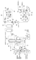
(Fourth Embodiment)
FIG. 4 shows the water content of the dried solid fuel and the supply amount of the hygroscopic powder containing an inorganic substance, which is introduced into each of the pulverizing means, the solid-fuel and air-stream conveying means for char, and the gasification furnace. The high-moisture coal gasification system provided with the control device which adjusts each is shown. In this embodiment, parts different from those of FIG. 3 shown in the third embodiment will be mainly described.
図4に示すように、本実施形態では、無機物を含む吸湿性の粉体4Eを、ガス化炉19にも供給する系統を新たに設ける。これは、固体燃料1に含まれる無機物(灰分)に、無機物を含む吸湿性の粉体4Eに含まれる無機物を加え、ガス化炉19内で溶融スラグ化する無機物の流量や溶融スラグの粘度を調整し、ガス化炉19内の下部に形成されるスラグコーティングを維持する機能も付加させるためである。
As shown in FIG. 4, in the present embodiment, a system for supplying the
また、本実施形態のガス化システムには、無機物を含む吸湿性の粉体4A、4B、4C、4D、4Eを供給する粉砕装置3、ロックホッパ5、チャーロックホッパ25、下段バーナ系のロックホッパ72、ガス化炉19のそれぞれの流量調整機能を組み込んだ制御装置78を設ける。この制御装置78における流量調整ロジックの概要について説明する。
In the gasification system of the present embodiment, the pulverizing
図5に示すように、まず、固体燃料1の分析値から、全水分(乾燥前の固体燃料に含まれる水分量)、付着水分(結合水分=全水分−付着水分で結合水分量を算出)、灰分(すなわち無機物)、灰融点および灰組成、工業分析(C、H、Oなど有機物の組成)を把握する。これにより、ガス化炉19の下部で灰溶融スラグ化させるための炉内温度、ガス化炉19に投入する固体燃料1の流量、炉内で溶融スラグ化する灰分(無機物)の流量を制御装置78に設定する。
As shown in FIG. 5, first, from the analysis value of the
次に、ガス化炉19に投入する固体燃料1の水分量、および固体燃料1をガス化する酸素量を設定する。これにより、乾燥装置2Aおよび乾燥装置2Bでそれぞれ乾燥後の固体燃料の目標水分(目標水分含有率)、粉砕装置3の運用温度とあわせて粉砕装置3で蒸発する水分量の予測値、冷却後の生成ガス22の温度と水蒸気の含有割合をそれぞれ設定する。本実施形態では、粉砕装置3で蒸発する水分量の予測値、および冷却後の生成ガス22の温度と水蒸気の含有割合を、制御装置78にそれぞれ設定する。
Next, the water content of the
さらに、不活性ガス8の供給温度、チャーロックホッパ25の内壁の目標温度を定め、上記の固体燃料1の分析値とあわせて、上段バーナ68に固体燃料1を供給するロックホッパ5、下段バーナ系のロックホッパ72、およびチャーロックホッパ25でそれぞれ蒸発する水分量の予測値をそれぞれ予測して、各予想値を制御装置78に設定する。
Further, the supply temperature of the
制御装置78は、これらの予測値と各機器の運用温度とから、粉砕装置3、ロックホッパ5、下段バーナ系のロックホッパ72、およびチャーロックホッパ25の内部で、蒸発した水分の凝縮を防ぐために必要な、無機物を含む吸湿性の粉体4A、4B、4C、4Dの流量をそれぞれ求める。
The
最後に、ガス化炉19内で溶融スラグ化する無機物の流量や溶融スラグの粘度を調整し、ガス化炉19内の下部に形成されるスラグコーティングを維持する観点で、上記の4A〜4Dよりガス化炉19に投入する無機物を含む吸湿性の粉体の総流量が不足する場合、この不足した無機物を含む吸湿性の粉体4Eをガス化炉19に投入するように、ガス化炉19に投入する紛体4Eの流量を求め、求めた流量の粉体4A、4B、4C、4Dがそれぞれ供給されるように、紛体供給系統に設けた制御弁等を制御して各粉体4A、4B、4C、4Dを供給する。
Finally, from the viewpoint of maintaining the slag coating formed in the lower part of the
なお、本実施形態には示さないが、ロックホッパ5に供給する無機物を含む吸湿性の粉体4Bで不足する分を、無機物を含む吸湿性の粉体4Fをフィードホッパ6に供給する制御ロジックとして、上記の制御装置78に組み込んでもよい。下段バーナ系のフィードホッパ73、チャーフィードホッパ26に供給する無機物を含む吸湿性の粉体4G、4Hの供給量も、上記と同様に設定するロジックとして、上記の制御装置78に組み込んでもよい。
Although not shown in the present embodiment, a control logic for supplying the hygroscopic powder 4F containing an inorganic substance to the feed hopper 6 for the shortage of the
以上のように、固体燃料1の分析値をもとに、乾燥後の固体燃料1の目標水分を設定し、この目標水分の固体燃料1の粉砕および気流搬送を成立させるための無機物を含む吸湿性の粉体の供給量を設定し、さらにガス化炉19に形成されるスラグコーティングロジック維持する機能も備えた制御装置78を備えることで、固体燃料1の乾燥動力を低減してエネルギー効率に優れ、かつ高水分の固体燃料1をガス化炉19に安定に搬送できる高水分の固体燃料のガス化システムを構築する。
As described above, based on the analysis value of the
なお、本発明は、一例として説明した上述の実施形態及び変形例に限定されることはなく、上述の実施形態等以外であっても、本発明に係る技術的思想を逸脱しない範囲であれば、設計等に応じて種々の変更が可能である。 The present invention is not limited to the above-described embodiments and modifications described as examples, and is not limited to the above-described embodiments and the like as long as the technical idea of the present invention is not deviated. Various modifications are possible according to the design, etc.
例えば、適用する高水分の固体燃料1として、褐炭以外(例えば、亜瀝青炭などの低品位炭、バイオマス、廃棄物など)を適用してもよい。
For example, as the high-moisture
本発明の高水分の固体燃料を適用するガス化システムとして有用である。 It is useful as a gasification system to which the high moisture solid fuel of the present invention is applied.
1…固体燃料、2,2A,2B…乾燥装置、 3…粉砕装置、4A,4B,4C,4D,4E,4F,4G,4H…無機物を含む吸湿性の粉体、5…ロックホッパ、6…フィードホッパ、7…固体燃料の移送弁、8…不活性ガス、9…ロックホッパ均圧弁、10…フィードホッパ均圧弁、11…圧力調整弁、12…固体燃料の搬送管、13,13A…固体燃料バーナ、14…空気、15…コンプレッサ、16…空気分離器、17…窒素、18…酸素、19…ガス化炉、20…生成ガス、21…生成ガス冷却部、 22…冷却後の生成ガス、23…脱塵装置、24…チャー、25…チャーロックホッパ、26…チャーフィードホッパ、27…チャー移送弁、28…チャーロックホッパ均圧弁、29…チャーフィードホッパ均圧弁、30…チャー系圧力調整弁、31…水洗塔、32…脱硫装置、33…脱硫後の生成ガス、34…生成ガスの熱交換器、35…生成ガスの加熱器、36…第一シフト反応器、37…第二シフト反応器、38…シフト反応後の生成ガス、39…シフト反応用の水、40…シフト反応後の生成ガスとシフト反応用の水の熱交換器、41…第一シフト反応後の生成ガスとシフト反応用の水の熱交換器、 42…シフト反応用水蒸気、43…シフト反応用水蒸気の加熱器、44…シフト反応後の生成ガスの冷却器、45…ノックアウトドラム、46…シフト反応後の生成ガスより回収された水、47…CO2吸収塔、48…CO2吸収後の生成ガス、49…CO2吸収したCO2吸収液、50…CO2吸収液の熱交換器、51…CO2吸収液の加熱器、52…CO2再生塔、53…CO2吸収液、54…CO2吸収液の昇圧ポンプ、55…再生加熱用のCO2吸収液、56…CO2吸収液の再生加熱器、57…CO2吸収液の再生加熱用蒸気、58…再利用CO2の流量調整弁、59…再利用CO2用コンプレッサ、60…飛散燃料を含む水蒸気、61…コンプレッサ、62…噴霧水、63…チャー搬送管、64…チャーバーナ、65…固体燃料の供給弁、66…チャーの供給弁、67…分配器、68…上段バーナ、69…上段バーナへの固体燃料の搬送管、70…下段バーナ、71…下段バーナ系の固体燃料の搬送管、72…下段バーナ系のロックホッパ、73…下段バーナ系のフィードホッパ、74…下段バーナ系の固体燃料の移送弁、75…下段バーナ系のロックホッパ均圧弁、76…下段バーナ系のフィードホッパ均圧弁、77…下段バーナ系の圧力調整弁、78…制御装置、101…回収CO2、102…再利用CO2、103…貯留CO2
DESCRIPTION OF
Claims (6)
無機物を含み、かつ吸湿性を有する粉体を、前記粉砕手段から前記ガス化炉までの少なくとも1箇所以上に供給する粉体供給系統を設け、
粉体の供給場所で蒸発する水分量の予測値に基づいて、前記粉体供給系統からの前記粉
体の供給量を求める制御装置を設けた
ことを特徴とする固体燃料のガス化システム。 A drying means for drying the solid fuel; a crushing means for crushing the solid fuel; an air flow carrying means for carrying the air flow of the solid fuel dried by the drying means and crushed by the crushing means to a gasification furnace; In the gasification system including the gasification furnace for gasifying the solid fuel that has been conveyed by the airflow conveying means,
Include inorganic and a powder having a moisture absorption, at least箇why on the supplied powder supply system to said gasification furnace provided from said comminution means,
Based on the predicted value of the amount of water that evaporates at the powder supply location, the powder from the powder supply system
A solid fuel gasification system, characterized in that a control device for determining the amount of body supply is provided .
無機物を含み、かつ吸湿性を有する粉体を、前記粉砕手段から前記ガス化炉までの少なくとも1箇所以上と、前記チャー気流搬送手段から前記ガス化炉までの少なくとも1箇所以上とに、それぞれ供給する粉体供給系統を設け、
粉体の供給場所で蒸発する水分量の予測値に基づいて、前記粉体供給系統からの前記粉
体の供給量を求める制御装置を設けた
ことを特徴とする固体燃料のガス化システム。 A drying means for drying the solid fuel; a crushing means for crushing the solid fuel; an air flow carrying means for carrying the air flow of the solid fuel dried by the drying means and crushed by the crushing means to a gasification furnace; The gasification furnace for gasifying the solid fuel carried by the airflow carrying means, the dedusting means for separating and collecting the char from the produced gas produced in the gasification furnace, and the dedusting means for collecting the char In a gasification system provided with a char airflow conveying means for conveying char to the gasification furnace by airflow,
A powder containing an inorganic substance and having a hygroscopic property is respectively supplied to at least one location from the crushing means to the gasification furnace and at least one location from the char airflow transport means to the gasification furnace. the powder supply system that is provided,
Based on the predicted value of the amount of water that evaporates at the powder supply location, the powder from the powder supply system
A solid fuel gasification system, characterized in that a control device for determining the amount of body supply is provided .
無機物を含み、かつ吸湿性を有する粉体を、前記粉砕手段から前記ガス化炉までの少なくとも1箇所以上に供給する粉体供給系統を設け、
粉体の供給場所で蒸発する水分量の予測値に基づいて、前記粉体供給系統からの前記粉
体の供給量を求める制御装置を設けた
ことを特徴とする固体燃料のガス化システム。 A drying means for drying the solid fuel; a crushing means for crushing the solid fuel; an air flow carrying means for carrying the air flow of the solid fuel dried by the drying means and crushed by the crushing means to a gasification furnace; The gasification furnace for gasifying the solid fuel carried by the airflow carrying means, and the dedusting means for separating and recovering the char from the produced gas produced in the gasification furnace are provided. In the gasification system in which the recovered char is supplied to the air flow transfer means and is air flow transferred to the gasification furnace together with the solid fuel,
Include inorganic and a powder having a moisture absorption, at least箇why on the supplied powder supply system to said gasification furnace provided from said comminution means,
Based on the predicted value of the amount of water that evaporates at the powder supply location, the powder from the powder supply system
A solid fuel gasification system, characterized in that a control device for determining the amount of body supply is provided .
前記気流搬送手段は、燃料用のホッパを有し、
前記粉体供給系統は、前記粉砕手段と前記燃料用のホッパのそれぞれに、前記粉体を個別に供給する
ことを特徴とする固体燃料のガス化システム。 The gasification system according to any one of claims 1 to 3, wherein:
The air flow carrying means has a hopper for fuel,
The solid fuel gasification system, wherein the powder supply system supplies the powder individually to each of the crushing means and the hopper for fuel.
前記気流搬送手段は、燃料用のホッパを有し、
前記チャー気流搬送手段は、チャー用のホッパを有し、
前記粉体供給系統は、前記粉砕手段と前記燃料用のホッパと前記チャー用のホッパのそれぞれに、前記粉体を個別に供給する
ことを特徴とする固体燃料のガス化システム。 The gasification system according to claim 2, wherein
The air flow carrying means has a hopper for fuel,
The char airflow carrying means has a hopper for char,
The solid fuel gasification system, wherein the powder supply system supplies the powder individually to each of the crushing means, the fuel hopper, and the char hopper.
前記乾燥手段は、第一及び第二の乾燥手段を有し、
前記粉砕手段は、前記第一の乾燥手段で乾燥された固体燃料を粉砕し、
前記第二の乾燥手段は、前記粉砕手段で粉砕された固体燃料を乾燥し、
前記気流搬送手段には、前記粉砕手段で粉砕された固体燃料を前記ガス化炉の上段バーナに供給する上段バーナ用気流搬送系統と、前記粉砕手段で粉砕された固体燃料を前記ガス化炉の下段バーナに供給する下段バーナ用気流搬送系統とが設けられ、
前記燃料用のホッパは、前記上段バーナ用気流搬送系統に設けられた上段バーナ用のホッパと、前記下段バーナ用気流搬送系統に設けられた下段バーナ用のホッパとを含み、
前記粉体供給系統は、前記上段バーナ用のホッパと前記下段バーナ用のホッパのそれぞれに、前記粉体を個別に供給する
ことを特徴とする固体燃料のガス化システム。 A gasification system according to claim 4 or claim 5,
The drying means has first and second drying means,
The crushing means crushes the solid fuel dried by the first drying means,
The second drying means dries the solid fuel crushed by the crushing means,
The airflow conveying means includes an upper stream burner airflow conveying system for supplying the solid fuel pulverized by the pulverizing means to the upper burner of the gasification furnace, and the solid fuel pulverized by the pulverizing means of the gasification furnace. An air flow carrier system for the lower burner that supplies the lower burner is provided,
The fuel hopper includes an upper burner hopper provided in the upper burner airflow transfer system and a lower burner hopper provided in the lower burner airflow transfer system,
The solid fuel gasification system, wherein the powder supply system supplies the powder individually to each of the hopper for the upper burner and the hopper for the lower burner.
Priority Applications (3)
| Application Number | Priority Date | Filing Date | Title |
|---|---|---|---|
| JP2018050243A JP6708683B2 (en) | 2018-03-16 | 2018-03-16 | Solid fuel gasification system |
| AU2019235819A AU2019235819A1 (en) | 2018-03-16 | 2019-03-15 | Solid fuel gasification system |
| PCT/JP2019/010842 WO2019177149A1 (en) | 2018-03-16 | 2019-03-15 | Solid fuel gasification system |
Applications Claiming Priority (1)
| Application Number | Priority Date | Filing Date | Title |
|---|---|---|---|
| JP2018050243A JP6708683B2 (en) | 2018-03-16 | 2018-03-16 | Solid fuel gasification system |
Publications (3)
| Publication Number | Publication Date |
|---|---|
| JP2019157094A JP2019157094A (en) | 2019-09-19 |
| JP2019157094A5 JP2019157094A5 (en) | 2020-04-16 |
| JP6708683B2 true JP6708683B2 (en) | 2020-06-10 |
Family
ID=67906822
Family Applications (1)
| Application Number | Title | Priority Date | Filing Date |
|---|---|---|---|
| JP2018050243A Active JP6708683B2 (en) | 2018-03-16 | 2018-03-16 | Solid fuel gasification system |
Country Status (3)
| Country | Link |
|---|---|
| JP (1) | JP6708683B2 (en) |
| AU (1) | AU2019235819A1 (en) |
| WO (1) | WO2019177149A1 (en) |
Families Citing this family (1)
| Publication number | Priority date | Publication date | Assignee | Title |
|---|---|---|---|---|
| JP7140726B2 (en) | 2019-08-28 | 2022-09-21 | 三菱重工業株式会社 | Carbon-based fuel gasification power generation system |
Family Cites Families (4)
| Publication number | Priority date | Publication date | Assignee | Title |
|---|---|---|---|---|
| JP2005126629A (en) * | 2003-10-27 | 2005-05-19 | Mitsubishi Heavy Ind Ltd | Facility for discharging material to be melted and method for operating facility for discharging material to be melted |
| JP4903623B2 (en) * | 2007-04-16 | 2012-03-28 | 財団法人電力中央研究所 | Method for producing coal gasification slag with adjusted composition |
| JP5840024B2 (en) * | 2012-02-17 | 2016-01-06 | 三菱日立パワーシステムズ株式会社 | Plant for combined power generation using wet fuel and fuel drying method thereof |
| JP2014149197A (en) * | 2013-01-31 | 2014-08-21 | Mitsubishi Heavy Ind Ltd | Device and method for detecting obstruction by particles of wet raw material |
-
2018
- 2018-03-16 JP JP2018050243A patent/JP6708683B2/en active Active
-
2019
- 2019-03-15 AU AU2019235819A patent/AU2019235819A1/en active Pending
- 2019-03-15 WO PCT/JP2019/010842 patent/WO2019177149A1/en active Application Filing
Also Published As
| Publication number | Publication date |
|---|---|
| AU2019235819A1 (en) | 2020-11-12 |
| JP2019157094A (en) | 2019-09-19 |
| WO2019177149A1 (en) | 2019-09-19 |
Similar Documents
| Publication | Publication Date | Title |
|---|---|---|
| CN101278034B (en) | System for the conversion of coal to a gas of specified composition | |
| CN101233215B (en) | A system for the conversion of carbonaceous feedstocks to a gas of a specified composition | |
| CN100577775C (en) | Coal gasification device for circulating fluidized bed and manufacturing method thereof | |
| TWI422739B (en) | Mild gasification combined-cycle powerplant | |
| CN102365350B (en) | Two-part dryer feed gasification system and method | |
| US20080202985A1 (en) | Method for recovery of hydrocarbon oils from oil shale and other carbonaceous solids | |
| WO2007037768A1 (en) | Solid waste gasification | |
| CN101952658A (en) | Method for supplying fuel to a gasification system | |
| CN101636559A (en) | Be used for method and apparatus at combustion gas and steam turbine (GuD) power station generation electric energy | |
| US10782021B2 (en) | Ash sintering gasifier | |
| CN102816606A (en) | Method for preparing hydrocarbon-rich combustible gas through gasification of combustible solid waste | |
| KR950011827B1 (en) | Proces for the conversion of coal and gypsum to valuble products | |
| CN101896581A (en) | Process and plant for producing char and fuel gas | |
| JP6708683B2 (en) | Solid fuel gasification system | |
| JP2013174415A (en) | Fluidized-bed drying device and gasification composite power generating system using coal | |
| CN201046952Y (en) | Circulating fluidized bed gasification apparatus | |
| AU2012248415A1 (en) | Fluidized bed drying apparatus and integrated coal gasification combined cycle system | |
| WO2012133549A1 (en) | Wet material supplying facility and gasification composite power generation system using wet material | |
| KR101100135B1 (en) | Coal gasifier for char recycle and the method thereof | |
| JPH01275694A (en) | Gasification of coal under pressure for purpose of operation of power apparatus | |
| JP5922338B2 (en) | Fluidized bed drying equipment and gasification combined cycle power generation system using fluidized bed drying equipment | |
| JP2014173790A (en) | Low-grade coal drying facility and gasification hybrid power system | |
| WO2008100012A1 (en) | Method for recovering resource from waste and resource recovery system therefor | |
| JP6231842B2 (en) | Gasification system with gasification furnace | |
| JP3788149B2 (en) | Combined power generation system |
Legal Events
| Date | Code | Title | Description |
|---|---|---|---|
| A521 | Written amendment |
Free format text: JAPANESE INTERMEDIATE CODE: A523 Effective date: 20200305 |
|
| A621 | Written request for application examination |
Free format text: JAPANESE INTERMEDIATE CODE: A621 Effective date: 20200305 |
|
| TRDD | Decision of grant or rejection written | ||
| A01 | Written decision to grant a patent or to grant a registration (utility model) |
Free format text: JAPANESE INTERMEDIATE CODE: A01 Effective date: 20200424 |
|
| A61 | First payment of annual fees (during grant procedure) |
Free format text: JAPANESE INTERMEDIATE CODE: A61 Effective date: 20200521 |
|
| R150 | Certificate of patent or registration of utility model |
Ref document number: 6708683 Country of ref document: JP Free format text: JAPANESE INTERMEDIATE CODE: R150 |