JP6708151B2 - Electric heater device - Google Patents
Electric heater device Download PDFInfo
- Publication number
- JP6708151B2 JP6708151B2 JP2017046396A JP2017046396A JP6708151B2 JP 6708151 B2 JP6708151 B2 JP 6708151B2 JP 2017046396 A JP2017046396 A JP 2017046396A JP 2017046396 A JP2017046396 A JP 2017046396A JP 6708151 B2 JP6708151 B2 JP 6708151B2
- Authority
- JP
- Japan
- Prior art keywords
- contact
- heat
- electric heater
- pipe
- heat exchange
- Prior art date
- Legal status (The legal status is an assumption and is not a legal conclusion. Google has not performed a legal analysis and makes no representation as to the accuracy of the status listed.)
- Active
Links
- XLYOFNOQVPJJNP-UHFFFAOYSA-N water Substances O XLYOFNOQVPJJNP-UHFFFAOYSA-N 0.000 claims description 61
- 238000010438 heat treatment Methods 0.000 claims description 26
- 238000003825 pressing Methods 0.000 claims description 10
- 238000011144 upstream manufacturing Methods 0.000 claims description 6
- 238000000034 method Methods 0.000 description 15
- 238000001816 cooling Methods 0.000 description 11
- 239000004065 semiconductor Substances 0.000 description 6
- 238000006243 chemical reaction Methods 0.000 description 4
- 238000001514 detection method Methods 0.000 description 4
- 239000000758 substrate Substances 0.000 description 4
- 230000000694 effects Effects 0.000 description 3
- 230000004048 modification Effects 0.000 description 2
- 238000012986 modification Methods 0.000 description 2
- 230000001681 protective effect Effects 0.000 description 2
- 238000003860 storage Methods 0.000 description 2
- 229910052782 aluminium Inorganic materials 0.000 description 1
- XAGFODPZIPBFFR-UHFFFAOYSA-N aluminium Chemical compound [Al] XAGFODPZIPBFFR-UHFFFAOYSA-N 0.000 description 1
- 238000009835 boiling Methods 0.000 description 1
- 239000000470 constituent Substances 0.000 description 1
- 238000005520 cutting process Methods 0.000 description 1
- 238000004512 die casting Methods 0.000 description 1
- 238000002474 experimental method Methods 0.000 description 1
- 238000010030 laminating Methods 0.000 description 1
- 239000007769 metal material Substances 0.000 description 1
Images


Classifications
-
- B—PERFORMING OPERATIONS; TRANSPORTING
- B60—VEHICLES IN GENERAL
- B60H—ARRANGEMENTS OF HEATING, COOLING, VENTILATING OR OTHER AIR-TREATING DEVICES SPECIALLY ADAPTED FOR PASSENGER OR GOODS SPACES OF VEHICLES
- B60H1/00—Heating, cooling or ventilating [HVAC] devices
- B60H1/02—Heating, cooling or ventilating [HVAC] devices the heat being derived from the propulsion plant
- B60H1/14—Heating, cooling or ventilating [HVAC] devices the heat being derived from the propulsion plant otherwise than from cooling liquid of the plant, e.g. heat from the grease oil, the brakes, the transmission unit
- B60H1/143—Heating, cooling or ventilating [HVAC] devices the heat being derived from the propulsion plant otherwise than from cooling liquid of the plant, e.g. heat from the grease oil, the brakes, the transmission unit the heat being derived from cooling an electric component, e.g. electric motors, electric circuits, fuel cells or batteries
-
- F—MECHANICAL ENGINEERING; LIGHTING; HEATING; WEAPONS; BLASTING
- F24—HEATING; RANGES; VENTILATING
- F24H—FLUID HEATERS, e.g. WATER OR AIR HEATERS, HAVING HEAT-GENERATING MEANS, e.g. HEAT PUMPS, IN GENERAL
- F24H1/00—Water heaters, e.g. boilers, continuous-flow heaters or water-storage heaters
- F24H1/10—Continuous-flow heaters, i.e. heaters in which heat is generated only while the water is flowing, e.g. with direct contact of the water with the heating medium
- F24H1/101—Continuous-flow heaters, i.e. heaters in which heat is generated only while the water is flowing, e.g. with direct contact of the water with the heating medium using electric energy supply
-
- H—ELECTRICITY
- H05—ELECTRIC TECHNIQUES NOT OTHERWISE PROVIDED FOR
- H05B—ELECTRIC HEATING; ELECTRIC LIGHT SOURCES NOT OTHERWISE PROVIDED FOR; CIRCUIT ARRANGEMENTS FOR ELECTRIC LIGHT SOURCES, IN GENERAL
- H05B3/00—Ohmic-resistance heating
- H05B3/40—Heating elements having the shape of rods or tubes
-
- B—PERFORMING OPERATIONS; TRANSPORTING
- B60—VEHICLES IN GENERAL
- B60H—ARRANGEMENTS OF HEATING, COOLING, VENTILATING OR OTHER AIR-TREATING DEVICES SPECIALLY ADAPTED FOR PASSENGER OR GOODS SPACES OF VEHICLES
- B60H1/00—Heating, cooling or ventilating [HVAC] devices
- B60H1/00271—HVAC devices specially adapted for particular vehicle parts or components and being connected to the vehicle HVAC unit
- B60H2001/00307—Component temperature regulation using a liquid flow
Landscapes
- Engineering & Computer Science (AREA)
- Physics & Mathematics (AREA)
- Thermal Sciences (AREA)
- Chemical & Material Sciences (AREA)
- Combustion & Propulsion (AREA)
- Mechanical Engineering (AREA)
- General Engineering & Computer Science (AREA)
- Air-Conditioning For Vehicles (AREA)
- Resistance Heating (AREA)
- Instantaneous Water Boilers, Portable Hot-Water Supply Apparatuses, And Control Of Portable Hot-Water Supply Apparatuses (AREA)
Description
本開示は、電気ヒータ装置に関する。 The present disclosure relates to electric heater devices.
従来、特許文献1に記載の電力変換装置がある。特許文献1に記載の電力変換装置は、半導体積層ユニットと、加圧部材とを備えている。半導体積層ユニットは、半導体モジュールと、半導体モジュールを冷却する冷却管とが交互に積層されることにより構成されている。加圧部材は、半導体積層ユニットを積層方向に加圧している。 Conventionally, there is a power conversion device described in Patent Document 1. The power conversion device described in Patent Document 1 includes a semiconductor laminated unit and a pressing member. The semiconductor laminated unit is configured by alternately laminating semiconductor modules and cooling pipes for cooling the semiconductor modules. The pressing member presses the semiconductor stacked units in the stacking direction.
特許文献1に記載の電力変換装置の構造は、発熱素子により水を加熱する電気ヒータ装置に適用することが可能である。具体的には、特許文献1に記載の電力変換装置において半導体モジュールに代えて発熱素子を用いれば、冷却管の内部を流れる水を加熱する電気ヒータ装置を実現することができる。 The structure of the power conversion device described in Patent Document 1 can be applied to an electric heater device that heats water with a heating element. Specifically, in the power conversion device described in Patent Document 1, if a heating element is used instead of the semiconductor module, an electric heater device that heats water flowing inside the cooling pipe can be realized.
ところで、このような電気ヒータ装置では、発熱素子を駆動させるための駆動回路等の電子部品が必要となる。また、電子部品が発熱する場合には、その冷却構造も必要となる。このような冷却構造としては、例えば所定の隙間を有して積層配置される冷却管を追加した上で、追加された冷却管の間に電子部品を配置する構造を採用することが考えられる。しかしながら、このような冷却構造を採用した場合、冷却管の数が増加することになるため、電気ヒータ装置の大型化が避けられないものとなる。 By the way, in such an electric heater device, electronic components such as a drive circuit for driving the heating element are required. Further, when the electronic component generates heat, a cooling structure for the heat is also required. As such a cooling structure, for example, it is conceivable to employ a structure in which cooling pipes that are stacked and arranged with a predetermined gap are added, and then electronic components are arranged between the added cooling pipes. However, when such a cooling structure is adopted, the number of cooling pipes increases, so that the electric heater device is inevitably increased in size.
本開示は、こうした実情に鑑みてなされたものであり、その目的は、電子部品を冷却することができるとともに、小型化の可能な電気ヒータ装置を提供することにある。 The present disclosure has been made in view of these circumstances, and an object thereof is to provide an electric heater device that can cool electronic components and can be downsized.
上記課題を解決する電気ヒータ装置は、複数の配管(21)と、発熱素子(30)と、ケース(40)と、電子部品(81,82,83)と、押し付け部材(50)と、を備える。複数の配管は、水が流入する流入管(70)と当該水が流出する排出管(71)との間に、熱交換部(20)として、内部に当該水が分配して流れ、かつ所定の隙間を有して積層されている。発熱素子は、複数の配管の隙間に配置され、電力の供給に基づき発熱する。ケースは、熱交換部及び発熱素子を内部に収容するとともに、熱交換部の複数の配管のうち積層方向の最端の配管と熱伝導可能に接触する接触部(44)を有する。電子部品は、ケースの接触部と熱伝導可能に設けられる。押し付け部材は、熱交換部側から、最端の配管と接触部とを押し付ける。
また、上記課題を解決する他の電気ヒータ装置は、複数の配管(21)と、発熱素子(30)と、ケース(40)と、電子部品(81,82,83)とを備える。複数の配管は、水が流入する流入管(70)と当該水が流出する排出管(71)との間に、熱交換部(20)として、内部に当該水が分配して流れ、かつ所定の隙間を有して積層されている。発熱素子は、複数の配管の隙間に配置され、電力の供給に基づき発熱する。ケースは、熱交換部及び発熱素子を内部に収容するとともに、熱交換部の複数の配管のうち積層方向の最端の配管と熱伝導可能に接触する接触部(44)を有する。電子部品は、ケースの接触部と熱伝導可能に設けられる。接触部は、ケースのうち流入管の貫通孔(42)と排出管の貫通孔(43)との間にある側壁(41)に相当する部分から、ケースの内部に向かって突出するように形成されるとともに、熱交換部における水の流れ方向の最も上流側の部分の最端の配管と接触するように配置されている。
An electric heater device for solving the above-mentioned problems includes a plurality of pipes (21), a heating element (30), a case (40), electronic components (81, 82, 83), and a pressing member (50). Prepare The plurality of pipes serve as a heat exchange part (20) between the inflow pipe (70) into which the water flows and the discharge pipe (71) from which the water flows out, and the water is distributed and flows inside the pipes. Are stacked with a gap of. The heating element is arranged in the gap between the plurality of pipes and generates heat based on the supply of electric power. The case has a contact part (44) that accommodates the heat exchanging part and the heat generating element inside, and is in contact with the endmost pipe in the stacking direction of the plurality of pipes of the heat exchanging part in a heat conductive manner. The electronic component is provided so as to be able to conduct heat with the contact portion of the case. The pressing member presses the endmost pipe and the contact part from the heat exchange part side.
Further, another electric heater device that solves the above problem includes a plurality of pipes (21), a heating element (30), a case (40), and electronic components (81, 82, 83). The plurality of pipes serve as a heat exchange part (20) between the inflow pipe (70) into which the water flows and the discharge pipe (71) from which the water flows out, and the water is distributed and flows inside the pipes. Are stacked with a gap of. The heating element is arranged in the gap between the plurality of pipes and generates heat based on the supply of electric power. The case has a contact part (44) that accommodates the heat exchanging part and the heat generating element inside, and is in contact with the endmost pipe in the stacking direction of the plurality of pipes of the heat exchanging part in a heat conductive manner. The electronic component is provided so as to be able to conduct heat with the contact portion of the case. The contact portion is formed so as to protrude toward the inside of the case from a portion of the case corresponding to a side wall (41) between the through hole (42) of the inflow pipe and the through hole (43) of the exhaust pipe. In addition, it is arranged so as to come into contact with the pipe at the end of the most upstream portion of the heat exchange section in the water flow direction.
この構成によれば、電子部品から発せられる熱が接触部に伝達される。接触部には熱交換部が接触しているため、接触部の熱は、熱交換部の配管を流れる水に吸収される。結果的に、電子部品から発せられる熱が、配管を流れる水に吸収されることになるため、電子部品を冷却することができる。また、積層配置された配管の間に電子部品を設けることにより電子部品の冷却を行う構造を採用する場合と比較すると、電子部品の冷却のために積層配置される別途の配管21が不要であるため、電気ヒータ装置を小型化することができる。
With this configuration, the heat generated from the electronic component is transferred to the contact portion. Since the heat exchange section is in contact with the contact section, the heat of the contact section is absorbed by the water flowing through the pipe of the heat exchange section. As a result, the heat generated from the electronic component is absorbed by the water flowing through the pipe, so that the electronic component can be cooled. Further, as compared with the case of adopting a structure in which electronic components are cooled by providing electronic components between the pipes that are stacked, a
なお、上記手段、特許請求の範囲に記載の括弧内の符号は、後述する実施形態に記載の具体的手段との対応関係を示す一例である。 The above-mentioned means and the reference numerals in parentheses in the claims are examples showing the corresponding relationship with the specific means described in the embodiments described later.
本開示によれば、電子部品を冷却することができるとともに、小型化の可能な電気ヒータ装置を提供できる。 According to the present disclosure, it is possible to provide an electric heater device that can cool electronic components and can be downsized.
以下、電気ヒータ装置の実施形態について図面を参照しながら説明する。説明の理解を容易にするため、各図面において同一の構成要素に対しては可能な限り同一の符号を付して、重複する説明は省略する。
<第1実施形態>
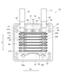
図1に示される本実施形態の電気ヒータ装置10は、例えば車両用空調装置においてヒータコアを循環する循環水を電気的に加熱することによりヒータコアの温度を上昇させるための装置として用いられる。ヒータコアの温度を上昇させることにより、車室内に吹き出される空気の温度を上昇させることができるため、車室内の暖房が可能となる。図1に示されるように、電気ヒータ装置10は、熱交換部20と、複数の発熱素子30と、ケース40と、押し付け部材50とを備えている。
Hereinafter, an embodiment of an electric heater device will be described with reference to the drawings. In order to facilitate understanding of the description, the same reference numerals are given to the same constituent elements in each drawing as much as possible, and overlapping description will be omitted.
<First Embodiment>
The
熱交換部20は、内部に水の流れる複数の扁平状の配管21がY方向に所定の隙間を有して積層配置された構造を有している。以下では、Y方向を「配管積層方向」とも称する。
各配管21の長手方向の一端部における配管積層方向Yの両側面には、筒状の連結部22a,22bがそれぞれ形成されている。隣り合う配管21,21のそれぞれの連結部22a,22bが互いに連結されることにより、各配管21の一端部が連通されている。また、各配管21の長手方向の他端部における配管積層方向Yの両側面には、筒状の連結部23a,23bがそれぞれ形成されている。隣り合う配管21,21のそれぞれの連結部23a,23bが互いに連結されることにより、各配管21の他端部が連通されている。
The
Cylindrical connecting
なお、配管積層方向Yの一端部に配置される配管21aには、連結部22aに代えて流入管70が接続されるとともに、連結部23aに代えて排出管71が接続されている。また、配管積層方向Yの他端部に配置される配管21bには、連結部22b,23bが形成されておらず、それらに対応する部分が閉塞されている。
The
熱交換部20では、流入管70に流入する水が各配管21の連結部22a,22bを通じて各配管21の内部に分配される。よって、熱交換部20では、図中に矢印Wで示される方向に水が流れる。各配管21を流れた水は各配管の連結部23a,23bにおいて集められた後、排出管71から排出される。
In the
発熱素子30は、複数の配管21,21の間に配置されている。発熱素子30は、電力の供給に基づき発熱する。発熱素子30と熱交換部20との間で熱交換が行われることにより、熱交換部20の内部を流れる水が加熱される。
ケース40は、四角箱状に形成されており、その内部に熱交換部20及び発熱素子30が収容されている。ケース40は、アルミニウム等の高い熱伝導性を有する金属材料により形成されている。ケース40の側壁41には、流入管70が挿入される貫通孔42と、排出管71が挿入される貫通孔43とが形成されている。流入管70及び排出管71は、これらの貫通孔42,43を通じてケース40の内部から外部に延びている。
The
The
ケース40には、熱交換部20の配管21aに接触する接触部44が形成されている。すなわち、接触部44は、配管積層方向Yにおいて熱交換部20の一端面に接触している。接触部44は、ケース40の側壁41における貫通孔42と貫通孔43との間に相当する部分からケース40の内部に向かって突出するように形成された厚肉部からなる。接触部44は、ダイカスト成形等によりケース40に一体的に形成されている。接触部44には、押し付け部材50により熱交換部20が押し付けられている。
The
具体的には、押し付け部材50は、ばね部材51と、プレート部材52とにより構成されている。プレート部材52は、熱交換部20の配管21bに面接触している。ばね部材51は、円弧状に湾曲した形状からなる板ばねからなる。ばね部材51の中央部はプレート部材52に接触している。ばね部材51の両端部は、ケース40に一体的に形成された円柱状の固定ピン45a,45bにより支持されている。ばね部材51は、固定ピン45a,45bとプレート部材52との間に圧縮された状態で挿入されている。よって、熱交換部20は、ばね部材51からプレート部材52を介して加わる弾性力により接触部44に押し付けられている。これにより、配管21と発熱素子30との密着性が高められるため、それらの間の熱伝導性を高めることができる。
Specifically, the pressing
なお、図1では、接触部44において熱交換部20が接触する部位のうち、熱交換部20における水の流れ方向Wの最も上流側の部分が接触する部位が第1接触部位P1として、また熱交換部20における水の流れ方向Wの最も下流側の部分が接触する部位が第2接触部位P2として図示されている。
In addition, in FIG. 1, among the parts of the
ケース40の四隅には、雌ねじ穴が形成された雌ねじ部46が形成されている。雌ねじ部46には、図示しない上蓋をケース40に組み付けるためのボルトがねじ込まれる。ケース40に上蓋が組み付けられることにより、ケース40の開口部分が閉塞される。
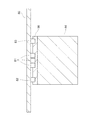
また、ケース40の内部には、雌ねじ穴が形成された円柱状の雌ねじ部47が複数形成されている。雌ねじ部47には、図2に示される基板80をケース40に組み付けるためのボルト48がねじ込まれる。これにより、基板80は、熱交換部20の全体及び接触部44の一部と対向するように配置される。
Inside the
基板80には、発熱素子30が実装されている。また、基板80には、発熱素子30を駆動させるための駆動回路や、電気ヒータ装置10の各種状態量を検出するためのセンサ素子、発熱素子30を制御する制御装置等の電子部品が実装されている。図2では、これらの電子部品のうち、駆動回路を構成するスイッチング素子81、温度センサ82,83、及び制御装置84が図示されている。スイッチング素子81は、IGBTやMOSFET等からなる。駆動回路では、スイッチング素子81のオン/オフの切り替えにより、発熱素子30への電力の供給及び停止を切り替えることが可能となっている。
The
図3に示されるように、スイッチング素子81及び温度センサ82,83は、熱伝導性部材90を介して接触部44と熱的に接合されている。熱伝導性部材90は、例えば熱伝導性シートからなる。図1に示されるように、第1温度センサ82は、接触部44における第1接触部位P1に近接した部分に設けられている。また、第2温度センサ83は、接触部44における第2接触部位P2に近接した部分に設けられている。このような構造により、スイッチング素子81を冷却することができるとともに、熱交換部20を流れる水の温度を温度センサ82,83により検出することができる。
As shown in FIG. 3, the switching
具体的には、スイッチング素子81から発せられる熱は熱伝導性部材90を通じて接触部44に伝達される。接触部44には、熱交換部20の配管21aが接触しているため、接触部44の熱は、熱交換部20の配管21aを流れる水に吸収される。結果的に、スイッチング素子81から発せられる熱が、配管21aを流れる水に吸収されることになるため、スイッチング素子81を冷却することができる。
Specifically, the heat generated from the switching
一方、第1温度センサ82は、接触部44における第1接触部位P1に近接した部分に設けられているため、第1接触部位P1の温度、あるいはそれと略同等の温度を検出することができる。第1接触部位P1は、接触部44において熱交換部20が接触する部位のうち、熱交換部20における水の流れ方向Wの最も上流側の部分が接触する部位である。よって、第1温度センサ82は、熱交換部20に流入する水の温度である流入水温T1を検出することが可能である。
On the other hand, since the
また、第2温度センサ83は、接触部44における第2接触部位P2に近接した部分に設けられているため、第2接触部位P2の温度、あるいはそれと略同等の温度を検出することができる。第2接触部位P2は、接触部44において熱交換部20が接触する部位のうち、熱交換部20における水の流れ方向Wの最も下流側の部分が接触する部位である。よって、第2温度センサ83は、熱交換部20から流出する水の温度である流出水温T2を検出することが可能である。
Further, since the
次に、電気ヒータ装置10の動作例について説明する。
制御装置84は、図4に示される処理を所定の周期で繰り返し実行する。図4に示されるように、制御装置84は、まず、ステップS10の処理として、上位ECUから送信される目標水温T*の情報を取得するとともに、ステップS11の処理として、温度センサ82,83の出力信号に基づいて流入水温T1及び流出水温T2の情報を取得する。そして、制御装置84は、ステップS11の処理に続いて、ステップS12の処理として、流入水温T1が保護水温Tth未満であるか否かを判断する。保護水温Tthは、水が沸騰する可能性があるか否かを判定することができるように予め実験等により定められており、制御装置84の記憶装置に記憶されている。
Next, an operation example of the
The
制御装置84は、ステップS12の処理で否定判断した場合には、すなわち流入水温T1が保護水温Tth以上である場合には、ステップS15の処理として、水の沸騰を回避するための保護処理を実行する。保護処理としては、例えばスイッチング素子81をオフさせて発熱素子30への電力の供給を遮断することにより発熱素子30を停止させる処理が行われる
制御装置84は、ステップS12の処理で肯定判断した場合には、すなわち流入水温T1が保護水温Tth未満である場合には、ステップS13の処理として、流出水温T2が目標水温T*未満であるか否かを判断する。制御装置84は、ステップS13の処理で肯定判断した場合には、すなわち流出水温T2が目標水温T*未満である場合には、ステップS14の処理として、発熱素子30を駆動させる。具体的には、制御装置84は、目標水温T*と流出水温T2との偏差に基づきデューティ比を演算するとともに、演算されたデューティ比に基づいてスイッチング素子81のオン/オフを制御することにより、発熱素子30を駆動させる。
When the
制御装置84は、ステップS14の処理を実行した後、一連の処理を一旦終了する。また、制御装置84は、ステップS13の処理で否定判断した場合にも、すなわち流出水温T2が目標水温T*以上である場合にも、一連の処理を一旦終了する。
以上説明した本実施形態の電気ヒータ装置10によれば、以下の(1)〜(3)に示される作用及び効果を得ることができる。
After executing the process of step S14, the
According to the
(1)電気ヒータ装置10では、接触部44にスイッチング素子81が設けられている。これにより、スイッチング素子81から発せられる熱が接触部44を介して配管21a内の水に吸収されるため、スイッチング素子81を冷却することができる。また、積層配置された配管21の間にスイッチング素子81を設けることによりスイッチング素子81の冷却を行う構造を採用する場合と比較すると、スイッチング素子81の冷却のために積層配置される別途の配管21が不要であるため、電気ヒータ装置10を小型化することができる。
(1) In the
(2)電気ヒータ装置10では、接触部44に温度センサ82,83が設けられている。具体的には、第1温度センサ82は、接触部44における第1接触部位P1に近接した部分に設けられている。また、第2温度センサ83は、接触部44における第2接触部位P2に近接した部分に設けられている。これにより、熱交換部20に流入する水の温度を第1温度センサ82により検出することができるとともに、熱交換部20から流出する水の温度を第2温度センサ83により検出することができる。
(2) In the
(3)接触部44は、スイッチング素子81及び温度センサ82,83が設けられる部分に熱伝導性部材90を有している。これにより、接触部44とスイッチング素子81との間の熱伝導性、並びに接触部44と温度センサ82,83との間の熱伝導性を高めることができるため、スイッチング素子81を冷却させ易くなるとともに、温度センサ82,83による温度の検出精度を高めることができる。
(3) The
(変形例)
次に、第1実施形態の電気ヒータ装置10の変形例について説明する。
図5に示されるように、接触部44は、熱交換部20の配管21aと接触する部分に熱伝導性部材91を有している。熱伝導性部材91は、例えば熱伝導性シートからなる。このような構成によれば、熱交換部20の配管21aと接触部44との間の熱伝導性を高めることができるため、スイッチング素子81を更に冷却させ易くなるとともに、温度センサ82,83による温度の検出精度を更に高めることができる。
(Modification)
Next, a modified example of the
As shown in FIG. 5, the
<第2実施形態>
次に、電気ヒータ装置10の第2実施形態について説明する。以下、第1実施形態の電気ヒータ装置10との相違点を中心に説明する。
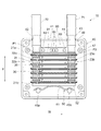
図6に示されるように、本実施形態の接触部44には、スイッチング素子81が設けられる部分と第1温度センサ82が設けられる部分との間にスリット100が形成されている。また、接触部44には、スイッチング素子81が設けられる部分と第2温度センサ83が設けられる部分との間にスリット101が形成されている。スリット100,101は、凹状の溝からなる。
<Second Embodiment>
Next, a second embodiment of the
As shown in FIG. 6, in the
以上説明した本実施形態の電気ヒータ装置10によれば、以下の(4)に示される作用及び効果を更に得ることができる。
(4)スリット100により、スイッチング素子81が設けられている部分と、第1温度センサ82が設けられている部分とが熱的に分断されるため、第1温度センサ82による温度の検出精度を向上させることができる。同様に、スリット101により、スイッチング素子81が設けられている部分と、第2温度センサ83が設けられている部分とが熱的に分断されるため、第2温度センサ83による温度の検出精度を向上させることができる。
According to the
(4) Since the
<他の実施形態>
なお、各実施形態は、以下の形態にて実施することもできる。
・スイッチング素子81及び温度センサ82,83を接触部44に接触させることにより、熱伝導性部材90を排除してもよい。
<Other Embodiments>
In addition, each embodiment can also be implemented in the following forms.
The heat
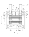
・接触部44には、スイッチング素子81及び温度センサ82,83のいずれか一方のみが設けられていてもよい。例えば接触部44に温度センサ82,83のみが設けられている場合には、図7に示されるように、接触部44には、第1温度センサ82と第2温度センサ83との間にスリット102が形成されていてもよい。これにより、第2実施形態の電気ヒータ装置10に類似の作用及び効果を得ることができる。
The
・接触部44には、スイッチング素子81及び温度センサ82,83以外の電子部品が設けられていてもよい。
・制御装置84が提供する手段及び/又は機能は、実体的な記憶装置に記憶されたソフトウェア及びそれを実行するコンピュータ、ソフトウェアのみ、ハードウェアのみ、あるいはそれらの組み合わせにより提供することができる。例えば制御装置84がハードウェアである電子回路により提供される場合、それは多数の論理回路を含むデジタル回路、又はアナログ回路により提供することができる。
The
The means and/or functions provided by the
・本開示は上記の具体例に限定されるものではない。上記の具体例に、当業者が適宜設計変更を加えたものも、本開示の特徴を備えている限り、本開示の範囲に包含される。前述した各具体例が備える各要素、及びその配置、条件、形状等は、例示したものに限定されるわけではなく適宜変更することができる。前述した各具体例が備える各要素は、技術的な矛盾が生じない限り、適宜組み合わせを変えることができる。 The present disclosure is not limited to the above specific examples. A person skilled in the art appropriately modified the above-described specific examples is also included in the scope of the present disclosure as long as the features of the present disclosure are provided. The elements included in the above-described specific examples, and the arrangement, conditions, shapes, and the like of the elements are not limited to those illustrated, but can be appropriately changed. The respective elements included in the above-described specific examples can be appropriately combined as long as there is no technical contradiction.
P1:第1接触部位
P2:第2接触部位
10:電気ヒータ装置
20:熱交換部
21:配管
30:発熱素子
40:ケース
44:接触部
50:押し付け部材
81:スイッチング素子(電子部品)
82:第1温度センサ(電子部品)
83:第2温度センサ(電子部品)
90,91:熱伝導性部材
100,101,102:スリット
P1: 1st contact part P2: 2nd contact part 10: Electric heater device 20: Heat exchange part 21: Piping 30: Heating element 40: Case 44: Contact part 50: Pressing member 81: Switching element (electronic part)
82: First temperature sensor (electronic component)
83: Second temperature sensor (electronic component)
90, 91: Heat
Claims (9)
前記複数の配管の前記隙間に配置され、電力の供給に基づき発熱する発熱素子(30)と、
前記熱交換部及び前記発熱素子を内部に収容するとともに、前記熱交換部の前記複数の配管のうち積層方向の最端の配管と熱伝導可能に接触する接触部(44)を有するケース(40)と、
前記ケースの前記接触部と熱伝導可能に設けられた電子部品(81,82,83)と、
前記熱交換部側から、前記最端の配管と前記接触部とを押し付ける押し付け部材(50)と、を備える
電気ヒータ装置。 Between the inflow pipe (70) into which the water flows and the discharge pipe (71) from which the water flows out, the water is distributed and flows inside as a heat exchange section (20) and has a predetermined gap. A plurality of pipes (21) stacked together,
A heating element (30) arranged in the gap between the plurality of pipes and generating heat based on the supply of electric power;
A case (40) that accommodates the heat exchanging portion and the heat generating element therein and has a contact portion (44) that comes into thermal contact with the endmost pipe in the stacking direction of the plurality of pipes of the heat exchanging portion. )When,
An electronic component (81, 82, 83) provided so as to be capable of conducting heat to the contact portion of the case;
An electric heater device comprising: a pressing member (50) for pressing the endmost pipe and the contact part from the heat exchange part side .
請求項1に記載の電気ヒータ装置。 The electric heater device according to claim 1.
前記複数の配管の前記隙間に配置され、電力の供給に基づき発熱する発熱素子(30)と、 A heating element (30) arranged in the gap between the plurality of pipes and generating heat based on the supply of electric power;
前記熱交換部及び前記発熱素子を内部に収容するとともに、前記熱交換部の前記複数の配管のうち積層方向の最端の配管と熱伝導可能に接触する接触部(44)を有するケース(40)と、 A case (40) that accommodates the heat exchanging part and the heat generating element therein and has a contact part (44) that comes into contact with the endmost pipe of the heat exchanging part in the stacking direction in a heat conductive manner. )When,
前記ケースの前記接触部と熱伝導可能に設けられた電子部品(81,82,83)と、を備え、 An electronic component (81, 82, 83) provided so as to be able to conduct heat and the contact portion of the case;
前記接触部は、前記ケースのうち前記流入管の貫通孔(42)と前記排出管の貫通孔(43)との間にある側壁(41)に相当する部分から、前記ケースの内部に向かって突出するように形成されるとともに、前記熱交換部における水の流れ方向の最も上流側の部分の前記最端の配管と接触するように配置されている The contact portion extends from the portion of the case corresponding to the side wall (41) between the through hole (42) of the inflow pipe and the through hole (43) of the discharge pipe toward the inside of the case. It is formed so as to project, and is arranged so as to come into contact with the pipe at the end of the most upstream portion in the water flow direction of the heat exchange portion.
電気ヒータ装置。 Electric heater device.
前記接触部に複数設けられ、
前記接触部には、
複数の前記電子部品のそれぞれが設けられている部分の間にスリット(100,101,102)が形成されている
請求項1〜3のいずれか一項に記載の電気ヒータ装置。 The electronic component is
A plurality is provided in the contact portion,
In the contact part,
The electric heater device according to any one of claims 1 to 3 , wherein slits (100, 101, 102) are formed between portions where the plurality of electronic components are provided.
前記発熱素子の駆動回路を構成するスイッチング素子(81)が含まれている
請求項1〜4のいずれか一項に記載の電気ヒータ装置。 The electronic parts include
The electric heater device according to claim 1, further comprising a switching element (81) that constitutes a drive circuit for the heating element.
温度センサ(82,83)が含まれている
請求項1〜4のいずれか一項に記載の電気ヒータ装置。 The electronic parts include
The electric heater device according to claim 1, further comprising a temperature sensor (82, 83).
前記温度センサは、
前記接触部における前記第1接触部位に近接した部分に設けられる第1温度センサ(82)と、
前記接触部における前記第2接触部位に近接した部分に設けられる第2温度センサ(83)と、からなる
請求項6に記載の電気ヒータ装置。 Of the parts of the contact part that the heat exchange part contacts, the part of the heat exchange part that contacts the most upstream part in the water flow direction is the first contact part (P1), and the water in the heat exchange part is When the site where the most downstream part in the flow direction of is in contact is the second contact site (P2),
The temperature sensor is
A first temperature sensor (82) provided in a portion of the contact portion near the first contact portion,
The electric heater device according to claim 6 , further comprising a second temperature sensor (83) provided in a portion of the contact portion that is close to the second contact portion.
前記熱交換部と接触する部分に熱伝導性部材(90)を有している
請求項1〜7のいずれか一項に記載の電気ヒータ装置。 The contact portion is
Electric heater device according to any one of claims 1 to 7, which has a heat conductive member (90) to the portion in contact with the heat exchange section.
前記電子部品が設けられる部分に熱伝導性部材(91)を有している
請求項1〜8のいずれか一項に記載の電気ヒータ装置。 The contact portion is
Electric heater device according to any one of claims 1 to 8 wherein said electronic component has a heat conductive member (91) to the portion provided.
Priority Applications (3)
| Application Number | Priority Date | Filing Date | Title |
|---|---|---|---|
| JP2017046396A JP6708151B2 (en) | 2017-03-10 | 2017-03-10 | Electric heater device |
| PCT/JP2018/008113 WO2018164007A1 (en) | 2017-03-10 | 2018-03-02 | Electric heater device |
| DE112018001261.1T DE112018001261T5 (en) | 2017-03-10 | 2018-03-02 | Electric heating device |
Applications Claiming Priority (1)
| Application Number | Priority Date | Filing Date | Title |
|---|---|---|---|
| JP2017046396A JP6708151B2 (en) | 2017-03-10 | 2017-03-10 | Electric heater device |
Publications (3)
| Publication Number | Publication Date |
|---|---|
| JP2018152195A JP2018152195A (en) | 2018-09-27 |
| JP2018152195A5 JP2018152195A5 (en) | 2019-06-13 |
| JP6708151B2 true JP6708151B2 (en) | 2020-06-10 |
Family
ID=63447607
Family Applications (1)
| Application Number | Title | Priority Date | Filing Date |
|---|---|---|---|
| JP2017046396A Active JP6708151B2 (en) | 2017-03-10 | 2017-03-10 | Electric heater device |
Country Status (3)
| Country | Link |
|---|---|
| JP (1) | JP6708151B2 (en) |
| DE (1) | DE112018001261T5 (en) |
| WO (1) | WO2018164007A1 (en) |
Families Citing this family (2)
| Publication number | Priority date | Publication date | Assignee | Title |
|---|---|---|---|---|
| JP2019184163A (en) | 2018-04-10 | 2019-10-24 | 株式会社デンソー | Electric heater device |
| JP2019184164A (en) | 2018-04-10 | 2019-10-24 | 株式会社デンソー | Electric heater device |
Family Cites Families (4)
| Publication number | Priority date | Publication date | Assignee | Title |
|---|---|---|---|---|
| JP2012096779A (en) * | 2010-10-07 | 2012-05-24 | Mitsubishi Heavy Ind Ltd | Heat-medium heating device and vehicle air conditioning device provided with the same |
| JP2014129090A (en) * | 2014-02-10 | 2014-07-10 | Mitsubishi Heavy Ind Ltd | Heat medium heating device and vehicle air conditioner using the same |
| JP6549919B2 (en) * | 2015-06-30 | 2019-07-24 | カルソニックカンセイ株式会社 | Fluid heating device |
| JP6537107B2 (en) | 2015-08-25 | 2019-07-03 | 矢崎総業株式会社 | Electrical connection box |
-
2017
- 2017-03-10 JP JP2017046396A patent/JP6708151B2/en active Active
-
2018
- 2018-03-02 WO PCT/JP2018/008113 patent/WO2018164007A1/en active Application Filing
- 2018-03-02 DE DE112018001261.1T patent/DE112018001261T5/en active Pending
Also Published As
| Publication number | Publication date |
|---|---|
| DE112018001261T5 (en) | 2019-12-19 |
| WO2018164007A1 (en) | 2018-09-13 |
| JP2018152195A (en) | 2018-09-27 |
Similar Documents
| Publication | Publication Date | Title |
|---|---|---|
| JP4506848B2 (en) | Semiconductor module | |
| US20070095378A1 (en) | Thermoelectric transducer | |
| JP2010119300A5 (en) | ||
| JP2016040770A (en) | Heat exchange plate for temperature management of battery pack | |
| WO2013031406A1 (en) | Module for adjusting battery temperature | |
| JP6708151B2 (en) | Electric heater device | |
| JP6575193B2 (en) | Power converter | |
| JP2007166820A (en) | Power conversion equipment | |
| JP6856682B2 (en) | Methods and systems for cooling power electronics systems built into batteries | |
| JP2006271063A (en) | Cooling structure of bus bar | |
| JP4725536B2 (en) | Power converter | |
| US20120074883A1 (en) | Electric power tool | |
| JP2009212137A (en) | Cooling device for heat generating element | |
| JP2013026116A (en) | System and method for controlling battery temperature | |
| JP6451166B2 (en) | Power converter | |
| JP2011216806A (en) | Electronic circuit device | |
| JP4834986B2 (en) | Thermoelectric unit | |
| WO2021010335A1 (en) | Battery temperature adjustment device | |
| JP7390835B2 (en) | electronic equipment | |
| JP6973313B2 (en) | Power converter | |
| JP5447191B2 (en) | Power converter | |
| JP2014053442A (en) | Plate laminated type cooling device | |
| JP2018152195A5 (en) | ||
| CN110612612B (en) | Thermoelectric power generation device | |
| JP4340890B2 (en) | Fever detection device |
Legal Events
| Date | Code | Title | Description |
|---|---|---|---|
| A521 | Request for written amendment filed |
Free format text: JAPANESE INTERMEDIATE CODE: A523 Effective date: 20190508 |
|
| A621 | Written request for application examination |
Free format text: JAPANESE INTERMEDIATE CODE: A621 Effective date: 20190508 |
|
| TRDD | Decision of grant or rejection written | ||
| A01 | Written decision to grant a patent or to grant a registration (utility model) |
Free format text: JAPANESE INTERMEDIATE CODE: A01 Effective date: 20200421 |
|
| A61 | First payment of annual fees (during grant procedure) |
Free format text: JAPANESE INTERMEDIATE CODE: A61 Effective date: 20200504 |
|
| R151 | Written notification of patent or utility model registration |
Ref document number: 6708151 Country of ref document: JP Free format text: JAPANESE INTERMEDIATE CODE: R151 |
|
| R250 | Receipt of annual fees |
Free format text: JAPANESE INTERMEDIATE CODE: R250 |
|
| R250 | Receipt of annual fees |
Free format text: JAPANESE INTERMEDIATE CODE: R250 |