JP6706206B2 - Rotor assembly and method for using same - Google Patents
Rotor assembly and method for using same Download PDFInfo
- Publication number
- JP6706206B2 JP6706206B2 JP2016553251A JP2016553251A JP6706206B2 JP 6706206 B2 JP6706206 B2 JP 6706206B2 JP 2016553251 A JP2016553251 A JP 2016553251A JP 2016553251 A JP2016553251 A JP 2016553251A JP 6706206 B2 JP6706206 B2 JP 6706206B2
- Authority
- JP
- Japan
- Prior art keywords
- rotor
- plate
- bucket
- stop plate
- rotor assembly
- Prior art date
- Legal status (The legal status is an assumption and is not a legal conclusion. Google has not performed a legal analysis and makes no representation as to the accuracy of the status listed.)
- Active
Links
Images


Classifications
-
- B—PERFORMING OPERATIONS; TRANSPORTING
- B04—CENTRIFUGAL APPARATUS OR MACHINES FOR CARRYING-OUT PHYSICAL OR CHEMICAL PROCESSES
- B04B—CENTRIFUGES
- B04B7/00—Elements of centrifuges
- B04B7/08—Rotary bowls
-
- B—PERFORMING OPERATIONS; TRANSPORTING
- B04—CENTRIFUGAL APPARATUS OR MACHINES FOR CARRYING-OUT PHYSICAL OR CHEMICAL PROCESSES
- B04B—CENTRIFUGES
- B04B5/00—Other centrifuges
- B04B5/04—Radial chamber apparatus for separating predominantly liquid mixtures, e.g. butyrometers
- B04B5/0407—Radial chamber apparatus for separating predominantly liquid mixtures, e.g. butyrometers for liquids contained in receptacles
- B04B5/0414—Radial chamber apparatus for separating predominantly liquid mixtures, e.g. butyrometers for liquids contained in receptacles comprising test tubes
- B04B5/0421—Radial chamber apparatus for separating predominantly liquid mixtures, e.g. butyrometers for liquids contained in receptacles comprising test tubes pivotably mounted
-
- B—PERFORMING OPERATIONS; TRANSPORTING
- B01—PHYSICAL OR CHEMICAL PROCESSES OR APPARATUS IN GENERAL
- B01D—SEPARATION
- B01D21/00—Separation of suspended solid particles from liquids by sedimentation
- B01D21/26—Separation of sediment aided by centrifugal force or centripetal force
- B01D21/262—Separation of sediment aided by centrifugal force or centripetal force by using a centrifuge
-
- B—PERFORMING OPERATIONS; TRANSPORTING
- B04—CENTRIFUGAL APPARATUS OR MACHINES FOR CARRYING-OUT PHYSICAL OR CHEMICAL PROCESSES
- B04B—CENTRIFUGES
- B04B11/00—Feeding, charging, or discharging bowls
- B04B11/04—Periodical feeding or discharging; Control arrangements therefor
- B04B2011/046—Loading, unloading, manipulating sample containers
-
- G—PHYSICS
- G01—MEASURING; TESTING
- G01N—INVESTIGATING OR ANALYSING MATERIALS BY DETERMINING THEIR CHEMICAL OR PHYSICAL PROPERTIES
- G01N35/00—Automatic analysis not limited to methods or materials provided for in any single one of groups G01N1/00 - G01N33/00; Handling materials therefor
- G01N35/00029—Automatic analysis not limited to methods or materials provided for in any single one of groups G01N1/00 - G01N33/00; Handling materials therefor provided with flat sample substrates, e.g. slides
- G01N2035/00099—Characterised by type of test elements
- G01N2035/00158—Elements containing microarrays, i.e. "biochip"
-
- G—PHYSICS
- G01—MEASURING; TESTING
- G01N—INVESTIGATING OR ANALYSING MATERIALS BY DETERMINING THEIR CHEMICAL OR PHYSICAL PROPERTIES
- G01N35/00—Automatic analysis not limited to methods or materials provided for in any single one of groups G01N1/00 - G01N33/00; Handling materials therefor
- G01N2035/00465—Separating and mixing arrangements
- G01N2035/00495—Centrifuges
-
- G—PHYSICS
- G01—MEASURING; TESTING
- G01N—INVESTIGATING OR ANALYSING MATERIALS BY DETERMINING THEIR CHEMICAL OR PHYSICAL PROPERTIES
- G01N35/00—Automatic analysis not limited to methods or materials provided for in any single one of groups G01N1/00 - G01N33/00; Handling materials therefor
- G01N35/02—Automatic analysis not limited to methods or materials provided for in any single one of groups G01N1/00 - G01N33/00; Handling materials therefor using a plurality of sample containers moved by a conveyor system past one or more treatment or analysis stations
- G01N35/04—Details of the conveyor system
- G01N2035/0439—Rotary sample carriers, i.e. carousels
- G01N2035/0446—Combinations of the above
- G01N2035/0449—Combinations of the above using centrifugal transport of liquid
Description
関連出願の相互参照
本出願は、参照によりその全体が本明細書に組み込まれる、2013年11月11日出願の米国仮出願第61/902,724号の利益を主張するものである。
CROSS REFERENCE TO RELATED APPLICATIONS This application claims the benefit of US Provisional Application No. 61/902,724 filed Nov. 11, 2013, which is hereby incorporated by reference in its entirety.
本出願は、参照によりその全体が本明細書に組み込まれる、2014年1月31日出願の米国仮出願第61/934,271号の利益を主張するものである。 This application claims the benefit of US Provisional Application No. 61/934,271 filed January 31, 2014, which is hereby incorporated by reference in its entirety.
開示の分野
本開示は、概して、ロータアセンブリ及びかかる回転子アセンブリを使用するための方法に関する。
FIELD OF THE DISCLOSURE The present disclosure relates generally to rotor assemblies and methods for using such rotor assemblies.
背景
化学、分子生物学、及び生物医科学などの分野では、研究者らは、試験を行うために小規模センサアレイにますます依存している。特に、分析物、特にビーズまたは粒子基材に付着した分析物が、試験のために小規模センサアレイ上に堆積する。センサの数が増加し、センサアレイ内の個々のセンサのサイズが縮小するにつれて、分析物をセンサアレイ内に堆積させることがますます困難になっている。ブラウン運動などの因子は、重力に対してますます支配的になっている。
BACKGROUND In fields such as chemistry, molecular biology, and biomedical sciences, researchers are increasingly relying on small sensor arrays to perform tests. In particular, analytes, especially those attached to beads or particle substrates, are deposited on the small scale sensor array for testing. As the number of sensors increases and the size of individual sensors within a sensor array shrinks, it becomes increasingly difficult to deposit analytes within the sensor array. Factors such as Brownian motion are becoming increasingly dominant to gravity.
添付の図面を参照することによって、本開示をよりよく理解することができ、その多くの特徴及び利点が当業者に明らかになる。 The present disclosure may be better understood, and its numerous features and advantages made apparent to those skilled in the art by referencing the accompanying drawings.
異なる図面内での同じ参照記号の使用は、同様または同一の品目を示す。 The use of the same reference symbols in different drawings indicates similar or identical items.
詳細な説明
例示的な実施形態では、ロータアセンブリは、中心軸を中心として回転するように構成されており、1つ以上のバケットを保持するように構成されたロータプレートを含む。バケットは、センサアレイ構成要素を固定することができる。加えて、ロータプレートは、ロータアセンブリの回転方向に延びる軸を中心としたバケットの回転を可能にする様式で、バケットに回転可能に取り付けられるか、または連結される。加えて、ロータアセンブリは、開放位置と閉鎖位置との間でロータプレートに対して回転可能である停止プレートを含んでもよい。開放位置では、バケットは、ロータアセンブリの回転の軌道に沿って延在びる軸を中心として回転することができる。閉鎖位置では、停止プレートは、バケットに係合し、それらの回転を防止する。バケットは、回転式アセンブリが回転しているときに、バケットが回転方向に沿って延びる軸を中心として所望の角度まで及びロータアセンブリの回転面に対して回転できるように加重されていてもよい。停止プレートは、ピペット操作ロボットのチップに係合するリングを更に含んでもよい。ピペット操作ロボットは、停止プレートが開放位置と閉鎖位置との間で移動することができるように、ロータプレートに対して停止プレートの回転を可能にするリングに係合することができる。
DETAILED DESCRIPTION In an exemplary embodiment, a rotor assembly includes a rotor plate configured to rotate about a central axis and configured to hold one or more buckets. The bucket can hold the sensor array components. Additionally, the rotor plate is rotatably attached to or coupled to the bucket in a manner that allows rotation of the bucket about an axis extending in the direction of rotation of the rotor assembly. Additionally, the rotor assembly may include a stop plate that is rotatable with respect to the rotor plate between an open position and a closed position. In the open position, the bucket can rotate about an axis that extends along the trajectory of rotation of the rotor assembly. In the closed position, the stop plates engage the buckets and prevent them from rotating. The bucket may be weighted to allow the bucket to rotate to a desired angle about an axis extending along the direction of rotation and to the plane of rotation of the rotor assembly as the rotary assembly rotates. The stop plate may further include a ring that engages the tip of the pipetting robot. The pipetting robot can engage a ring that allows rotation of the stop plate relative to the rotor plate so that the stop plate can move between open and closed positions.
更なる例示的な実施形態では、ロータアセンブリの停止プレートは、閉鎖位置に位置付けられてもよく、バケットを装填位置に固定し、バケットがロータアセンブリの回転面の外側に回転するのを防止する。バケット内にセンサアレイアセンブリが挿入され得、センサアレイアセンブリに溶液がアプライされ得る。停止プレートは、ロータアセンブリのスピン中にバケットの回転を可能にする開放位置に移動し得る。その後、停止プレートが、閉鎖位置に逆に戻され得、バケットを固定して、バケットの回転を制限する。バケット及びセンサアレイアセンブリが、再びスピンされ得る一方で、バケットは、固定され、ロータアセンブリの回転方向に延びる軸を中心として回転することができない。その後、残りの溶液が、センサアレイアセンブリから除去され得、センサアレイアセンブリが、バケットから取り外され得、試験システム内に設置され得る。 In a further exemplary embodiment, the stop plate of the rotor assembly may be positioned in the closed position to secure the bucket in the loading position and prevent the bucket from rotating outside the plane of rotation of the rotor assembly. The sensor array assembly can be inserted into the bucket and the solution can be applied to the sensor array assembly. The stop plate may move to an open position that allows rotation of the bucket during spinning of the rotor assembly. The stop plate can then be reversed back to the closed position, locking the bucket and limiting rotation of the bucket. While the bucket and sensor array assembly can be spun again, the bucket is stationary and cannot rotate about an axis extending in the rotational direction of the rotor assembly. The remaining solution may then be removed from the sensor array assembly, the sensor array assembly may be removed from the bucket, and installed in the test system.
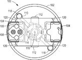
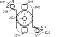
図1及び図2に示される例示的な実施形態では、ロータアセンブリ100が、中心軸116を中心として回転またはスピンすることができる。一実施例では、ロータアセンブリ100が、ロータプレート102を含んでもよく、そのロータプレート102が、1つ以上のバケット104に係合する心棒120を含む。示された実施例では、ロータプレート102は、2つのバケット104を受容するように構成される。あるいは、ロータアセンブリ及びロータプレート102は、少なくとも1つのバケット、例えば、少なくとも2つのバケット、少なくとも4つのバケット、または少なくとも6つのバケットなど、ただし20を超えないバケットを受容するように構成され得る。バケット104は、センサアレイ構成要素106及び関連する蓋108を受容するように構成される。蓋108は、溶液の供給またはセンサアレイ構成要素106からの溶液の回収を支援し得る。
In the exemplary embodiment shown in FIGS. 1 and 2,
ロータアセンブリ100は、停止プレート110を更に含んでもよい。停止プレート110は、バケット104に係合する翼部112を含んでもよく、心棒120を中心としたバケットの回転を制限する。停止プレート110は、例えば、ピペット操作ロボットのチップによって、係合され得るリング118を更に含んでもよい。ピペット操作ロボット及び任意選択的に関連する遠心分離機モータを使用して、停止プレート110は、中心軸116を中心としてまたはロータプレート102に対して回転し得、図1に示されるような開放位置から図2に示されるような閉鎖位置まで翼部112を移動させ、その位置では、翼部112が、バケット104に係合し、心棒120を中心としたバケット104の回転を制限する。
The
加えて、ロータアセンブリ100は、ロータアセンブリ100を遠心分離機モータの中心軸116に固定する連結器114を含んでもよい。
Additionally, the
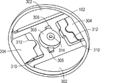
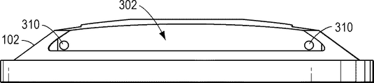
図3、図4、及び図5に示されるように、例示的なロータプレート102は、バケット104を受容する開口部304を含む。特に、ロータプレート102は、バケット104(図1及び図2に示される)に係合する心棒120を受容する凹部310を含む。心棒120は、開口部304内に延在することができ、バケットに係合することができる。ロータプレート102はまた、開口部302を含み、その開口部302を通して停止プレートリング118(図1及び図2に示される)が、例えば、ピペット操作ロボットによって、係合され得る。ロータプレート102は、停止プレート110及び連結器114(図1及び図2に示される)に係合する中心凹部306を含む。任意選択的に、中心凹部306は、連結器114の翼部(例えば、図9及び図10に示される翼部1012)に係合するスロット308を含んでもよく、連結器114及びロータプレート102(図1及び図2に示される)の相対運動を制限することができる。特に、連結器114が回転すると、翼部は、スロット308に十分に係合し、ロータプレート102を制限された遊びで連結器114と共に移動させる。ロータプレート102はまた、フィッティングを受容する中心穴314を含んでもよい。
As shown in FIGS. 3, 4, and 5, the
ロータプレート102のバケット開口部304に近接して、ロータプレート102は、上部停止表面312及び後部停止表面316を含んでもよい。停止プレート110が閉鎖位置にあるときに、停止プレート102は、バケット104またはセンサアレイアセンブリに上部停止表面312または逆戻り防止表面316との接触を強いられ得、凹部310に係合する心棒120を中心としたバケットの回転を制限する。
Proximal to the
図6、図7、及び図8は、例示的な停止プレート110の図を含む。停止プレート110は、停止プレート110がロータプレート102及び連結器114(図1及び図2に示される)に対して回転可能であるように、連結器114及びロータプレート102に係合することができる。停止プレート110は、閉鎖位置にあるときにバケット104に係合する翼部112を含む。特定の実施例では、翼部112は、停止プレート110が閉鎖しているときにバケット104に係合しかつバケットを閉鎖位置に押す面取りされた表面702を含んだ。停止プレート110は、連結器114の中心シャフトに係合する中心開口部808を更に含んでもよい。
6, 7, and 8 include views of an
更に、停止プレート110は、アーム704及び末端リング118を含む。リング118は、軸116を中心とした連結器114及びロータプレート102に対する停止プレート110の相対的回転(図1及び図2に示される)を可能にするように係合され得る。任意選択的に、停止プレート110は、開放位置と閉鎖位置との間を移動するときに連結器114の停止表面(例えば、図9及び図10の停止表面1004)に係合する停止表面710を含む。更に、停止プレート110は、磁石を受容する凹部706を含んでもよい。磁石は、連結器114への停止プレート110の固定を支援し得、ロータアセンブリのスピン中に停止プレート110をある位置に維持し得る。具体的には、連結器114またはロータプレート102は、停止プレート110が閉鎖または開放位置にあるときに引力を与える補完的な磁石を含んでもよい。停止プレート110が閉鎖または開放位置にありかつ停止プレート110のリング118が係合されていないとき、停止プレート110は、ロータプレート102及び連結器114と共に中心軸を中心としてスピンする。
In addition,
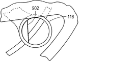
図8に示されるように、末端リング118は、面取りされたスリップ902で部分的に埋められ得る。面取りされたスリップ902は、ロータアセンブリが回転する間にチップが停止プレート110を保持することを可能にするように構成され得、停止プレートをその開始位置に対して90°の位置まで動かし、停止プレート110を開放位置から閉鎖位置までまたはその逆に移動させる
As shown in FIG. 8, the
図9及び図10は、例示的な連結器114の図を含む。連結器114は、図3に示されるように、ロータプレート102のスロット308に係合する翼部1012を含んでもよい。ロータプレート102と係合されると、翼部1012は、連結器114に対するロータプレート102の動きを制限する。連結器114は、ロータプレート102の軸受に係合するための中心シャフト面取り部1002を更に含んでもよく、停止プレート110に係合するための接触表面1008を含んでもよい。停止プレート110は、停止プレート110が開放位置から閉鎖位置に及び逆に回転するときに連結器114の停止表面1004に係合する停止表面710を含んでもよい。加えて、連結器114は、停止プレート110の磁石に対する引き付けによって停止プレート110を所望の位置に固定することができる磁石を受容する凹部1006を含んでもよい。図10に示されるように、連結器114は、連結器114及びロータアセンブリ100を遠心分離機モータのモータシャフトに連結するシャフト連結1110を更に含んでもよい。
9 and 10 include views of an
図11及び図12は、例示的なバケット104の図を含む。例示的なバケット104は、ロータプレート102に取り付けられた心棒120に摺動可能に係合するチャネル1202を含む。バケット104は、センサアレイ構成要素に係合するパターニングされた表面1204を更に含んでもよい。開口部1206が、センサアレイアセンブリを更に固定するか、またはセンサアレイアセンブリの突出端部を収容するために提供され得る。
11 and 12 include views of an
バケット104の底部表面には、図12に示されるように、停止表面1308が、面取りされた表面1310間に位置付けられ得る。停止プレート110が閉鎖位置に移動すると、停止プレート110の翼部112の面取りされた表面702がバケット104の面取りされた表面1310に係合し、バケット104を固定し、かつバケット104の回転を制限する位置にバケット104を移動させる。更に、バケット104は、バケット104がロータアセンブリ100と係合されないときに、バケット104が卓上表面上に平坦に位置することを可能にするレールまたは他の特徴部1312を含んでもよい。
At the bottom surface of
特に、図13及び図14に示されるように、バケット104は、チャネル1202に沿って心棒120に係合するロータプレート102における位置まで摺動され得る。蓋108を含むセンサアレイアセンブリ106がバケット104内に挿入されかつ停止プレート110の翼部112がバケット104の停止表面1308に係合するとき、バケット104は、ロータプレート102の上部停止表面312または後部停止表面316に対して固定される。示されるように、バケット104は、停止プレートが閉鎖位置にあるときに、ロータアセンブリ100の回転面に対して水平または負の角度を有することができる。例えば、バケット104及び関連するセンサアレイアセンブリ106は、停止プレートが閉鎖位置にあるときに、ロータアセンブリの回転面に対して5°〜−15°の範囲にある角度、例えば、5°〜−10°の角度、または0°〜−5°の角度などを有することができる。本明細書において、正の角度は、センサアレイアセンブリまたはバケット104の上部が、ロータアセンブリの中心軸に向くように傾いていることを示す。停止プレート110が開放位置にあるときに、バケット104は心棒118を中心としてスイングすることができる。特に、ロータアセンブリ100が中心軸116を中心として回転しているとき、バケット104は、ロータアセンブリ100のスピン中に少なくとも45°、例えば少なくとも75°など、または少なくとも80°の角度を有するように加重されていてもよい。ロータアセンブリ100のスピン中に、バケット104は、ロータアセンブリ100の回転面に対して、85°〜110°の範囲にある位置あるいは角度、例えば85°〜105°の角度など、または85°〜95°の角度、例えば約90°などまでスイングし得る。
In particular, as shown in FIGS. 13 and 14,
ロータアセンブリの動作を更に示すために、図15は、ロータ位置1における開放位置にあるロータを示す。チップが停止プレートのリングに係合でき、ロータプレートは、例えば反時計回りに、90°回転し得、ロータ閉鎖位置2においてロータプレート及びバケットに係合する。停止プレートを開放するために、ロータアセンブリが、ロータ位置3まで反時計回りに90°回転し得る。チップが停止プレートのリング内にアプライされ得、ロータプレートは、時計回りに90°回転して、停止プレートを係脱し、ロータ開放位置4に移動することができる。ロータアセンブリは、ロータアセンブリの閉鎖及び開放のプロセスを再び始めるために時計回りに180°更に回転し得る。 To further illustrate the operation of the rotor assembly, FIG. 15 shows the rotor in the open position at rotor position 1. The tip can engage the ring of the stop plate and the rotor plate can rotate 90°, eg counterclockwise, to engage the rotor plate and bucket in the rotor closed position 2. To open the stop plate, the rotor assembly may rotate 90° counterclockwise to rotor position 3. The tip can be applied in the ring of the stop plate and the rotor plate can be rotated 90° clockwise to disengage the stop plate and move to the rotor open position 4. The rotor assembly may further rotate 180° clockwise to restart the process of closing and opening the rotor assembly.
特に、ロータアセンブリは、試料をセンサアレイに装填するために使用され得る。図16に示されるように、方法1700は、任意選択的に、1702に示されるように、蓋をセンサアセンブリに取り付けることを含む。特に、蓋は、センサアレイに出入りする溶液のピペット操作のためのより容易なアクセスを提供し得る。
In particular, the rotor assembly can be used to load the sample into the sensor array. As shown in FIG. 16,
センサアレイアセンブリは、1704に示されるように、バケット内に挿入される。特に、バケットは、回転子アセンブリがスピンするときにセンサアレイアセンブリを固定する。 The sensor array assembly is inserted into the bucket, as shown at 1704. In particular, the bucket secures the sensor array assembly as the rotor assembly spins.
任意選択的に、バケットは、ロータアセンブリ内に挿入され、溶液が、1706に示されるように、センサアレイにアプライされる。特に、バケットを適所に保持するために停止プレートが閉鎖位置にある間に、溶液がアプライされ得る。あるいは、溶液は、バケットをロータプレート内に挿入する前にアプライされ得る。 Optionally, the bucket is inserted into the rotor assembly and the solution is applied to the sensor array, as shown at 1706. In particular, the solution may be applied while the stop plate is in the closed position to hold the bucket in place. Alternatively, the solution can be applied before inserting the bucket into the rotor plate.
1708に示されるように、停止プレートは、バケット及びセンサアレイアセンブリが、回転式アセンブリの回転方向に延びる軸に対してスイングすることを可能にする開放位置に位置付けられ得る。特に、バケットは、ロータアセンブリの回転方向に沿った方向に延びる軸を中心として正の角度まで回転するように加重され得る。 As shown at 1708, the stop plate may be positioned in an open position that allows the bucket and sensor array assembly to swing about an axis extending in the rotational direction of the rotary assembly. In particular, the bucket may be weighted to rotate to a positive angle about an axis extending in a direction along the rotational direction of the rotor assembly.
停止プレートが開放位置に移動した時点で、バケット及びセンサアレイアセンブリを含むロータアセンブリが、1710に示されるように、スピンされ得る。結果として、バケット及びセンサアレイアセンブリは、ロータアセンブリのスピン中に少なくとも45°、例えば少なくとも75°など、または少なくとも80°の角度まで回転し得る。ロータアセンブリのスピン中に、バケットは、ロータアセンブリの回転面に対して、85°〜110°の範囲にある位置または角度、例えば85°〜105°の角度など、または85°〜95°の角度、例えば約90°などまでスイングし得る。 Once the stop plate has moved to the open position, the rotor assembly including the bucket and sensor array assembly may be spun, as shown at 1710. As a result, the bucket and sensor array assembly may rotate to an angle of at least 45°, such as at least 75°, or at least 80° during spinning of the rotor assembly. During spinning of the rotor assembly, the bucket is positioned or angled relative to the plane of rotation of the rotor assembly in a range of 85° to 110°, such as an angle of 85° to 105°, or an angle of 85° to 95°. , For example up to about 90°.
スピンに次いで、停止プレートは、1712に示されるように、バケット及びセンサアレイアセンブリのスピン角度を制限する閉鎖位置に位置付けられ得る。例えば、停止プレートは、バケットのスピン角度をほぼゼロまたはわずかに負に制限し得る。任意選択的に、停止プレートが閉鎖位置にありバケットの動きを制限している間に、回転式アセンブリ及びセンサアレイアセンブリが、1714に示されるように、スピンされ得る。特に、負の角度でのスピンが、センサアレイアセンブリからの溶液の除去を容易にし得る。 Following the spin, the stop plate may be positioned in a closed position that limits the spin angle of the bucket and sensor array assembly, as shown at 1712. For example, the stop plate may limit the spin angle of the bucket to near zero or slightly negative. Optionally, the rotary assembly and sensor array assembly may be spun, as shown at 1714, while the stop plate is in the closed position to limit bucket movement. In particular, spins at negative angles can facilitate removal of solution from the sensor array assembly.
残りの溶液が、1716に示されるように、例えば、蓋内の凹部から残りの溶液をピペット操作することによって、センサアレイアセンブリから除去され得る。次いで、センサアレイアセンブリが、1718に示されるように、バケットから取り外され得、別個の試験装置において使用され得る。 The remaining solution may be removed from the sensor array assembly, as shown at 1716, for example, by pipetting the remaining solution from a recess in the lid. The sensor array assembly can then be removed from the bucket and used in a separate test rig, as shown at 1718.
特定の実施例では、センサアレイアセンブリは、標的ポリヌクレオチドを配列決定するときに特に使用される。図17の方法1800に示されるように、ポリヌクレオチド試料は、1802に示されるように、増幅され得る。特に、試料は、ビーズまたは微粒子基材上で増幅され得る。
In a particular example, the sensor array assembly is particularly used in sequencing a target polynucleotide. As shown in
1804に示されるように、増幅された試料、特に、ビーズまたは粒子基材が、センサアレイ構成要素にアプライされ得る。特に、増幅された試料を含む溶液が、センサアレイ構成要素にアプライまたは装填され、様々な角度条件下でスピンを受け、ビーズまたは微粒子基材をセンサアレイ構成要素内に固定する。次いで、センサアレイ構成要素が、配列決定装置内に挿入され得、1806に示されるように、センサアレイ構成要素に装填された増幅された試料が配列決定され得る。 As shown at 1804, an amplified sample, in particular a bead or particle substrate, can be applied to the sensor array component. In particular, a solution containing the amplified sample is applied or loaded onto the sensor array component and subjected to spin under various angular conditions to immobilize the bead or particulate substrate within the sensor array component. The sensor array component can then be inserted into the sequencing device and the amplified sample loaded into the sensor array component can be sequenced, as shown at 1806.
かかるロータアセンブリは、ピペット操作ロボットアセンブリにおける特定の使用法を見い出す。図18は、例示的な構成を示す。システム1900は、移動デバイス、例えば、3つの直交軸の範囲上でシリンジポンプ1904を移動させるように動作可能なxyzロボット1902などを含む。システム1900は、シリンジポンプ1904によって有用なピペットチップを収納するためのチップラック1906を更に含む。システム1900はまた、空の管を収納し得るか、または試薬片管、例えば試薬片1908などを収納し得る管ラック1916を含んでもよい。更なる実施例では、システム1900は、感温試薬、例えば酵素などを収納するための冷却ブロック1910を含んでもよい。システム1900は、サーモサイクラー(thermocycler)1912、1つ以上の解乳化遠心分離機1914、及びモータを有するビーズ装填遠心分離機1918を更に含んでもよい。特に、ビーズ装填遠心分離機1918は、ロータアセンブリ、例えば、上記のロータアセンブリの実施形態などを含んでもよい。システム1900は、光センサまたはチップ取り外しデバイスを更に含んでもよい。
Such rotor assemblies find particular use in pipetting robot assemblies. FIG. 18 shows an exemplary configuration.
動作中、移動デバイス1902は、チップラック1906からチップを取り出すように及びシステム1900の様々な機能を実行するように、シリンジポンプ1904の位置を操作する。例えば、シリンジポンプ1904は、不混和性連続相によって取り囲まれた水性不連続相において酵素及び試料を含む乳濁液を形成するために試薬ラック1916の試薬と共に利用され得る。例えば、試料及び酵素溶液が、冷却試薬ブロック1910内に収納され得る。乳濁液は、試薬ラック1916における管内に形成され得る。特に、乳濁液は、高速ピペット操作によって生成され得る。別の実施例では、乳濁液が、制限を通したピペット操作によって生成され得る。
In operation,
乳濁液の形成に次いで、乳濁液は、移動デバイス1902及びシリンジポンプ1904を使用してサーモサイクラー1912上のサーモサイクラープレートに移され得る。サーモサイクラープレート1912は、ポリメラーゼ連鎖反応(PCR)またはリコンビナーゼポリメラーゼ増幅(RPA)を行うために利用され得る。PCR反応の完了後、乳濁液は、サーモサイクラー1912から解乳化遠心分離機1914のうちの1つに移され得る。乳濁液が、界面活性剤溶液を有する管を含む解乳化遠心分離機1914内に注入され得る。遠心分離機が回転する際、乳濁液が、遠心分離機内に注入される。乳濁液が遠心分離機1914の管内で界面活性剤溶液に接触すると、水性相成分が溶液中で動かされる一方で、油性相成分が管から除去される。
Following formation of the emulsion, the emulsion may be transferred to a thermocycler plate on
PCRまたはRPAプロセスは、いくつかの標的ポリヌクレオチドを含む増幅されたビーズを生成し得る。かかる増幅されたビーズは、洗浄され得、濃縮システムを使用して他の水溶液成分から分離され得る。特に、試薬ラック1916が、増幅されたビーズに結び付く磁性粒子を使用する濃縮を可能にする磁石システムを用いて変化させられ得る。
The PCR or RPA process can produce amplified beads containing some target polynucleotides. Such amplified beads can be washed and separated from other aqueous solution components using a concentration system. In particular, the
濃縮に次いで、ビーズが、装填遠心分離機1918を使用して、配列決定デバイス、例えば、配列決定副産物を検出するために構成されたチップなどに移され得、かつ装填され得る。例えば、増幅されたビーズを含む溶液の一定分量が、装填遠心分離機1918内のラック上に配置された配列決定デバイス上のポートに注入され得る。遠心分離機1918は、例えば、上記のように、装填を容易にするために、位置付けられ、かつスピンされ得る。特に、シリンジポンプ1904に取り付けられたチップは、停止プレートを開放位置と閉鎖位置との間で移動させるために停止プレートのリング内に位置付けられ得る。本プロセスは、装填密度を改善するために1回以上繰り返され得る。結果として、試料から増幅された標的ヌクレオチドを組み込む、増幅された粒子が装填された配列決定デバイスは、最小限の人的相互作用で提供される。
Following concentration, the beads can be transferred and loaded using a
プロセス全体にわたって、シリンジポンプ1914は、ピペットチップラック1906から取得した種々のピペットチップを利用することができる。更に、磁石の動き、解乳化遠心分離機1914内への管の装填、装填遠心分離機の設定、または他の機能を支援するチップが提供され得る。シリンジポンプ1904からのチップの取り外しを支援するために、チップ取り外しデバイスが提供され得る。
Throughout the process, the
他の実施形態では、停止プレートが、2つの別個の構成要素から形成され得、磁石が、異なる構成要素上の異なる場所に位置付けられ得、バケットの心棒が、バケットに固定され得、ロータプレートへの心棒の固定とは対照的な異なるサイズのものであり得る。例示的な実施形態が図19〜図26に示されるが、示された特徴部は、実施形態間で交換可能であり得る。 In other embodiments, the stop plate may be formed from two separate components, the magnets may be located at different locations on different components, the bucket mandrel may be fixed to the bucket, and the rotor plate Can be of different sizes as opposed to fixing the mandrel. Although exemplary embodiments are shown in FIGS. 19-26, the features shown may be interchangeable between embodiments.
図19に示されるように、遠心分離機2000が、ロータプレート2004に固定され得るバケット2002を含む。上部停止プレート2006は、ロータプレート2004と同軸状に位置付けられる。上部停止プレート2006が下部停止プレート2008に連結され得、下部停止プレート2008はバケット2002に係合する翼部を含む。ロータプレート2004が連結器2010に固定され、その連結器2010は、ロータアセンブリをモータ2014のシャフトに固定する。上部停止プレート2006及び下部停止プレート2008が、連結器2010に回転可能に固定され得る。ロータアセンブリは、ケース2012の内側に適合し得る。
As shown in FIG. 19,
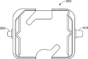
図20、図21、及び図22は、上部停止プレート2006の図を含む。上記の停止プレートと同様に、上部停止プレート2006が、ロボット、特にピペット操作ロボットに係合する開口部2016であって、ロータプレート2004に対する上部及び下部停止プレートの回転を可能にする開口部2016を含む。加えて、上部停止プレート2006は、例えば、上部停止プレート2006及び下部停止プレート2008がバケット2002と係合されるときに、バケット2002内のデバイス上のポートに対するアクセスを提供する窓2018を含んでもよい。上部停止プレート2006はまた、連結器2010に係合する中心穴2022を含んでもよい。上部停止プレート2006の端部は、ケース2012の内部表面と合致する表面2020で構成され得る。
20, 21, and 22 include views of the
図21における上部停止プレート2006の底面図に示されるように、上部停止プレート2006は、上部停止プレート2006を下部停止プレート2008に固定する連結アーム2102を含んでもよい。上部停止プレート2006はまた、上部停止プレート2006及び下部停止プレート2008の位置を指定された位置に保持することを支援するロータプレート2004上の磁石に係合する磁石2104を含んでもよい。あるいは、磁石は、下部停止プレート2008上の位置であり得る。
As shown in the bottom view of
図22における側面図に示されるように、上部停止プレート2006は、下部停止プレート2008に係合する連結構造2102において終端する拡張部2202を含んでもよい。あるいは、下部停止プレート2008は、上部停止プレート2006に係合する拡張部及び連結構造を含んでもよい。かかる構成を使用して、上部停止プレート2006は、ロータプレート2004の上に存在し得、下部停止プレート2008は、ロータアセンブリの回転の軸に対してロータプレート2004の下に存在し得る。
As shown in the side view in FIG. 22, the
図23は、下部停止プレート2008の図を含む。下部停止プレートは、ロータプレート2004上に配置されたバケット2002に係合する翼部2302を含む。翼部2302は、閉鎖位置においてバケット2002に係合してそれらの回転を防止するようにバケットを固定する水平平坦表面2312を含んでもよい。下部停止プレート2008はまた、上部停止プレート2006に係合するアーム2304及び連結位置2318を含んでもよい。下部停止プレート2008は、連結器2010上の停止表面に係合する停止表面2314を更に含んでもよい。
FIG. 23 includes a view of the
図24は、連結器2010の更なる例示的な実施形態を示す。連結器2010は、ロータプレート2004に係合する翼部2412を含む。加えて、連結器2010は、下部停止プレート2008、ロータプレート2004、または上部停止プレート2006に係合する中心シャフト2402を含む。上部停止プレート2006及び下部停止プレート2008は、連結器2010に対する回転を可能にする様式で連結器2010に係合する。特に、上部停止プレート2006または下部停止プレート2008は、互いに係合されると、上記の停止プレートと同様に機能し、第1の位置と第2の位置との間で、例えば、閉鎖位置と開放位置との間で移動し得る。連結器2010は、2つの位置のうちの一方にあるときに下部停止プレート2008の停止表面2314に係合する停止表面2404を含む。
FIG. 24 shows a further exemplary embodiment of the
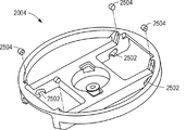
ロータプレート2004は、上記のロータプレートに関して記載される特徴部と同様の特徴部を含む。示された実施例では、ロータプレートが、上部停止プレート2006内の埋め込み型磁石に係合できる埋め込み型磁石2504を含む。特に、停止プレート2006または2008は、ロータアセンブリがモータ2014の中心軸の周りに回転しているときに、磁石の相互作用によって開放または閉鎖位置に保持され得る。
The
更なる実施例では、ロータプレート2004が、バケット2002の心棒を受容するスロット2502を含んでもよい。かかる実施例では、心棒が、バケット2002に固定され、バケット2002をロータプレート2004に回転可能に連結するようにスロット2502内に摺動され得る。特定の実施例では、ロータプレート2004のスロット2502は、異なるサイズの心棒を受容するように構成され得る。特に、バケット2002を受容する凹部の時計回り側のスロット2502は、反時計回り側のスロットとは異なるサイズを有し得る。図26に示されるように、バケット2002は、異なる直径または異なる形状の心棒2602及び2604を用いて構成され得る。そのように、バケットは、単一の様式でロータプレート2004に係合することができ、ロータプレート2004とのバケット2002の不正確な係合を防止する。
In a further example,
第1の態様では、ロータアセンブリが、第1の軸を中心として回転するロータプレート;ロータプレートに回転可能に取り付けられ、かつ第2の軸を中心として回転するバケット;開放位置と閉鎖位置との間でロータプレートに対して第1の軸を中心として回転する停止プレートであって、閉鎖位置にあるときに、停止プレートが、ロータアセンブリの回転面に対するバケットの角度位置を固定するようにバケットに係合することができる、停止プレート;を含む。 In a first aspect, a rotor assembly includes a rotor plate rotating about a first axis; a bucket rotatably mounted on the rotor plate and rotating about a second axis; an open position and a closed position. A stop plate that rotates about a first axis with respect to the rotor plate between, when in the closed position, the stop plate causes the bucket to lock the angular position of the bucket relative to the plane of rotation of the rotor assembly. A stop plate, which is engageable.
第1の態様の一実施例では、停止プレートが、停止プレートが閉鎖位置まで移動しているときに、バケットの表面に係合する面取りされた表面を有する翼部を含む。例えば、バケットは、停止プレートの面取りされた表面に係合する面取りされた表面を含む。 In one embodiment of the first aspect, the stop plate includes a wing having a chamfered surface that engages a surface of the bucket when the stop plate is in the closed position. For example, the bucket includes a chamfered surface that engages a chamfered surface of the stop plate.
第1の態様の別の実施例及び上記実施例では、停止プレートが、アーム及びリングを含む。例えば、ロータプレートが、開口部を含み、その開口部を通して、停止プレートのリングがアクセスされ得る。一実施例では、リングが、面取りされたスリップを含む。 In another embodiment of the first aspect and above, the stop plate comprises an arm and a ring. For example, the rotor plate may include an opening through which the ring of the stop plate may be accessed. In one example, the ring includes a chamfered slip.
第1の態様の更なる実施例及び上記実施例では、ロータアセンブリが、ロータプレート及び停止プレートに係合する中心シャフトを有する連結器を含む。例えば、連結器は、停止プレートが開放または閉鎖位置にあるときに、停止プレートの停止表面に係合する停止表面を含む。別の実施例では、連結器が、停止プレートが開放または閉鎖位置にあるときに、停止プレートの磁石に引き付ける磁石を含む。追加の実施例では、ロータプレートが、連結部を受容するスロットを有する凹部、ロータプレートのスロットに係合する連結部の翼部を含む。 In a further embodiment of the first aspect and above, the rotor assembly includes a coupler having a central shaft that engages the rotor plate and the stop plate. For example, the coupler includes a stop surface that engages the stop surface of the stop plate when the stop plate is in the open or closed position. In another embodiment, the coupler includes a magnet that attracts the stop plate magnet when the stop plate is in the open or closed position. In an additional embodiment, the rotor plate includes a recess having a slot for receiving the coupling, a wing of the coupling engaging the slot of the rotor plate.
第1の態様の追加の実施例及び上記実施例では、ロータプレートが、停止プレートが閉鎖位置にあるときに、バケットまたはセンサアレイアセンブリに係合する上部停止表面を含む。 In an additional embodiment of the first aspect and above, the rotor plate includes an upper stop surface that engages the bucket or sensor array assembly when the stop plate is in the closed position.
第1の態様の別の実施例及び上記実施例では、ロータプレートが、停止プレートが閉鎖位置にあるときにバケットに係合する後部停止表面を含む。 In another embodiment of the first aspect and above, the rotor plate includes a rear stop surface that engages the bucket when the stop plate is in the closed position.
第1の態様の更なる実施例及び上記実施例では、ロータアセンブリがスピンしているときに、バケットが、ロータアセンブリの回転面に対するある角度位置が与えられるように加重されている。 In a further embodiment of the first aspect and above, the bucket is weighted such that when the rotor assembly is spinning, the bucket is given an angular position with respect to the plane of rotation of the rotor assembly.
第2の態様では、システムが、三次元の動きを有するピペット操作ロボットと、第1の態様または第1の態様の複数の実施例のうちのいずれか1つのロータアセンブリを含む遠心分離機と、を含む。 In a second aspect, a system includes a pipetting robot having three-dimensional movement, a centrifuge including a rotor assembly of the first aspect or any one of the embodiments of the first aspect; including.
第3の態様では、センサアレイアセンブリに装填する方法が、ロータアセンブリの停止プレートが閉鎖位置にあるときに、ロータアセンブリのバケット内に配置されたセンサアレイアセンブリに溶液をアプライする工程;停止プレートを開放位置まで移動させる工程;ロータアセンブリをスピンさせる工程であって、バケットがロータアセンブリの回転面に対して正の角度の方へ回転する、スピンさせる工程;停止プレートを閉鎖位置まで移動させる工程;及び、ロータアセンブリをスピンさせる工程であって、バケットがロータアセンブリの回転面に対して水平または負の角度の方へ回転する、スピンさせる工程、を含む。 In a third aspect, a method of loading a sensor array assembly includes applying a solution to a sensor array assembly located in a bucket of a rotor assembly when the stop plate of the rotor assembly is in a closed position; Moving to an open position; spinning the rotor assembly, wherein the bucket rotates toward a positive angle with respect to the plane of rotation of the rotor assembly, spinning; moving the stop plate to a closed position; And spinning the rotor assembly, wherein the bucket rotates to a horizontal or negative angle with respect to a plane of rotation of the rotor assembly.
第3の態様の一実施例では、ロータアセンブリが、第1の態様または第1の態様の複数の実施例のうちのいずれか1つのロータアセンブリである。 In an example of the third aspect, the rotor assembly is the rotor assembly of any one of the first aspect or embodiments of the first aspect.
第4の態様では、ロータアセンブリを設定する方法が、チップをロータアセンブリの停止プレートのリング内に挿入する工程であって、チップが停止プレートの移動を防止する、挿入する工程;停止プレートに対してロータアセンブリのロータプレートを回転させる工程;及び、リングからチップを取り外す工程、を含む。 In a fourth aspect, a method of setting a rotor assembly is the step of inserting a tip into a ring of a stop plate of a rotor assembly, the tip preventing movement of the stop plate; Rotating the rotor plate of the rotor assembly according to the present invention; and removing the tip from the ring.
第4の態様の一実施例では、停止プレートが、ロータプレートが回転するときに、ロータプレートに回転可能に連結されたバケットに係合する翼部を含む。 In an embodiment of the fourth aspect, the stop plate includes wings that engage a bucket rotatably coupled to the rotor plate as the rotor plate rotates.
第4の態様の別の実施例では、停止プレートが、ロータプレートが回転するときに、ロータプレートに回転可能に連結されたバケットから係脱する翼部を含む。 In another embodiment of the fourth aspect, the stop plate includes vanes that disengage from a bucket rotatably coupled to the rotor plate as the rotor plate rotates.
第4の態様の更なる実施例及び上記実施例では、方法が、ロータアセンブリを180°回転させる工程;チップをリング内に挿入する工程;及び、ロータプレートを停止プレートに対して90°回転させる工程、を更に含む。 In a further embodiment of the fourth aspect and above, the method comprises rotating the rotor assembly 180°; inserting the tip into the ring; and rotating the rotor plate 90° with respect to the stop plate. The method further includes:
概要または実施例に記載される上述の活性が全て必要というわけではなく、特定の活性の一部を必要としない可能性があり、上述の活性に加えて1つ以上の活性を更に行う可能性があるということを留意されたい。更には、活性を記載する順序は、必ずしも活性が行われる順序ではない。 Not all of the above activities described in the summary or examples may be required and may not require some of the particular activities, and may additionally perform one or more of the above activities. Please note that there is. Furthermore, the order of describing activities is not necessarily the order in which the activities are performed.
[本発明1001]
以下を備える、ロータアセンブリ:
第1の軸を中心として回転する、ロータプレート;
前記ロータプレートに回転可能に取り付けられ、かつ第2の軸を中心として回転する、バケット;及び
開放位置と閉鎖位置との間で前記ロータプレートに対して前記第1の軸を中心として回転する停止プレートであって、前記閉鎖位置にあるときに前記ロータアセンブリの回転面に対する前記バケットの角度位置を固定するように前記バケットに係合することができる、停止プレート。
[本発明1002]
前記停止プレートが、前記停止プレートが前記閉鎖位置まで移動しているときに前記バケットの表面に係合する面取りされた表面を有する翼部を含む、本発明1001のロータアセンブリ。
[本発明1003]
前記バケットが、前記停止プレートの前記面取りされた表面に係合する面取りされた表面を含む、本発明1002のロータアセンブリ。
[本発明1004]
前記停止プレートが、アーム及びリングを含む、本発明1001〜1003のいずれかのロータアセンブリ。
[本発明1005]
前記ロータプレートが開口部を含み、該開口部を通して前記停止プレートの前記リングがアクセスされ得る、本発明1004のロータアセンブリ。
[本発明1006]
前記リングが、面取りされたスリップを含む、本発明1004のロータアセンブリ。
[本発明1007]
前記ロータプレート及び前記停止プレートに係合する中心シャフトを有する連結器を更に含む、本発明1001〜1006のいずれかのロータアセンブリ。
[本発明1008]
前記連結器が、前記停止プレートが開放位置または閉鎖位置にあるときに前記停止プレートの停止表面に係合する停止表面を含む、本発明1007のロータアセンブリ。
[本発明1009]
前記連結器が、前記停止プレートが開放位置または閉鎖位置にあるときに前記停止プレートの磁石を引き付ける磁石を含む、本発明1007のロータアセンブリ。
[本発明1010]
前記ロータプレートが、連結部を受容するスロットを有する凹部を含み、前記連結部の翼部が、前記ロータプレートの前記スロットに係合する、本発明1007のロータアセンブリ。
[本発明1011]
前記ロータプレートが、前記停止プレートが閉鎖位置にあるときに前記バケットまたはセンサアレイアセンブリに係合する上部停止表面を含む、本発明1001〜1010のいずれかのロータアセンブリ。
[本発明1012]
前記ロータプレートが、前記停止プレートが閉鎖位置にあるときに前記バケットに係合する後部停止表面を含む、本発明1001〜1011のいずれかのロータアセンブリ。
[本発明1013]
前記バケットが、前記ロータアセンブリがスピンしているときに、前記ロータアセンブリの回転面に対するある角度位置が与えられるように加重されている、本発明1001〜1012のいずれかのロータアセンブリ。
[本発明1014]
以下を備える、システム:
三次元の動きを有するピペット操作ロボット;及び
本発明1001〜1013のいずれかのロータアセンブリを含む遠心分離機。
[本発明1015]
以下の工程を含む、センサアレイアセンブリに装填する方法:
ロータアセンブリの停止プレートが閉鎖位置にあるときに、前記ロータアセンブリのバケット内に配置されたセンサアレイアセンブリに溶液をアプライする工程;
前記停止プレートを開放位置まで移動させる工程;
前記ロータアセンブリをスピンさせる工程であって、前記バケットが、前記ロータアセンブリの回転面に対して正の角度の方へ回転する、スピンさせる工程;
前記停止プレートを前記閉鎖位置まで移動させる工程;及び
前記ロータアセンブリをスピンさせる工程であって、前記バケットが、前記ロータアセンブリの前記回転面に対して水平または負の角度の方へ回転する、スピンさせる工程。
[本発明1016]
前記ロータアセンブリが、本発明1001〜1003のいずれかのロータアセンブリである、本発明1015の方法。
[本発明1017]
以下の工程を含む、ロータアセンブリを設定する方法:
前記ロータアセンブリの停止プレートのリング内にチップを挿入する工程であって、前記チップが前記停止プレートの移動を防止する、挿入する工程;
前記ロータアセンブリのロータプレートを前記停止プレートに対して回転させる工程;及び
前記リングから前記チップを取り外す工程。
[本発明1018]
前記停止プレートが、前記ロータプレートが回転するときに前記ロータプレートに回転可能に連結されたバケットに係合する翼部を含む、本発明1017の方法。
[本発明1019]
前記停止プレートが、前記ロータプレートが回転するときに前記ロータプレートに回転可能に連結されたバケットから係脱する翼部を含む、本発明1017または本発明1018の方法。
[本発明1020]
前記ロータアセンブリを180°回転させる工程;
前記チップを前記リング内に挿入する工程;及び
前記ロータプレートを前記停止プレートに対して90°回転させる工程
を更に含む、本発明1017〜1019のいずれかの方法。
上述の明細書には、特定の実施形態を参照して概念を記載している。しかしながら、当業者であれば、以下の特許請求の範囲に記載される本発明の範囲から逸脱することなく、様々な修正及び変更が加えられ得ることを理解する。したがって、本明細書及び図面は、限定的な意味ではなく例示的な意味でみなされるべきであり、そのような全ての修正は本発明の範囲内に含まれることが意図される。
[Invention 1001]
A rotor assembly, including:
A rotor plate rotating about a first axis;
A bucket rotatably attached to the rotor plate and rotating about a second axis; and
A stop plate that rotates about the first axis relative to the rotor plate between an open position and a closed position, the angular position of the bucket relative to a plane of rotation of the rotor assembly when in the closed position. A stop plate capable of engaging the bucket to secure the.
[Invention 1002]
1001. The rotor assembly of invention 1001, wherein the stop plate comprises a wing having a chamfered surface that engages a surface of the bucket when the stop plate is moving to the closed position.
[Invention 1003]
The rotor assembly of
[Invention 1004]
The rotor assembly of any of the present invention 1001-1003, wherein said stop plate comprises an arm and a ring.
[Invention 1005]
The rotor assembly of
[Invention 1006]
The rotor assembly of
[Invention 1007]
The rotor assembly of any one of the present invention 1001-1006, further comprising a coupler having a central shaft that engages the rotor plate and the stop plate.
[Invention 1008]
The rotor assembly of claim 1007, wherein the coupler includes a stop surface that engages a stop surface of the stop plate when the stop plate is in the open or closed position.
[Invention 1009]
The rotor assembly of invention 1007, wherein the coupler includes a magnet that attracts a magnet of the stop plate when the stop plate is in an open or closed position.
[Invention 1010]
The rotor assembly of claim 1007, wherein the rotor plate includes a recess having a slot for receiving a connection, the wings of the connection engaging the slot in the rotor plate.
[Invention 1011]
The rotor assembly of any of the present inventions 1001-1010, wherein the rotor plate includes an upper stop surface that engages the bucket or sensor array assembly when the stop plate is in the closed position.
[Invention 1012]
The rotor assembly of any of the present inventions 1001-1011, wherein the rotor plate includes a rear stop surface that engages the bucket when the stop plate is in the closed position.
[Invention 1013]
The rotor assembly of any one of the present inventions 1001-1012, wherein the bucket is weighted to provide an angular position with respect to a plane of rotation of the rotor assembly when the rotor assembly is spinning.
[Invention 1014]
A system with:
Pipetting robot with three-dimensional movement; and
A centrifuge including the rotor assembly of any of the invention 1001-1013.
[Invention 1015]
A method of loading the sensor array assembly including the following steps:
Applying a solution to the sensor array assembly located in the bucket of the rotor assembly when the stop plate of the rotor assembly is in the closed position;
Moving the stop plate to an open position;
Spinning the rotor assembly, wherein the bucket is rotated toward a positive angle with respect to a plane of rotation of the rotor assembly;
Moving the stop plate to the closed position; and
Spinning the rotor assembly, the bucket rotating to a horizontal or negative angle with respect to the plane of rotation of the rotor assembly.
[Invention 1016]
The method of the present invention 1015, wherein the rotor assembly is the rotor assembly of any of the present invention 1001-1003.
[Invention 1017]
A method of setting up a rotor assembly, including the following steps:
Inserting a tip into a ring of a stop plate of the rotor assembly, wherein the tip prevents movement of the stop plate;
Rotating a rotor plate of the rotor assembly relative to the stop plate; and
Removing the tip from the ring.
[Invention 1018]
The method of invention 1017, wherein the stop plate comprises vanes that engage a bucket rotatably coupled to the rotor plate as the rotor plate rotates.
[Invention 1019]
The method of invention 1017 or invention 1018, wherein said stop plate comprises a vane disengaging from a bucket rotatably coupled to said rotor plate as said rotor plate rotates.
[Invention 1020]
Rotating the rotor assembly 180°;
Inserting the tip into the ring; and
Rotating the rotor plate by 90° with respect to the stop plate
The method of any of the present invention 1017-1019, further comprising:
The above specification describes the concepts with reference to particular embodiments. However, one of ordinary skill in the art appreciates that various modifications and changes can be made without departing from the scope of the present invention as set forth in the claims below. Accordingly, the specification and drawings are to be regarded in an illustrative rather than a restrictive sense, and all such modifications are intended to be included within the scope of the present invention.
本明細書で使用される場合、用語「含む(comprises)」、「含んでいる(comprising)」、「含む(includes)」、「含んでいる(including)」、「有する(has)」、「有している(having)」、またはそれらの他の変形は、非排他的包含を網羅することを意図する。例えば、プロセス、方法、物品、または装置は、特徴部のリストを含むが、必ずしもそれらの特徴部のみに限定されず、明確に記載されていない特徴部、またはそのようなプロセス、方法、物品、または装置に固有の他の特徴部を含んでもよい。更に、それとは反対に、明確に記載されない場合、「または」は、排他的な「または」ではなく、包括な「または」を指す。例えば、以下のうちの任意の1つによって条件AまたはBが満たされる:Aが正しく(または存在する)かつBが誤りである(または存在しない)、Aが誤りであり(または存在しない)かつBが正しい(または存在する)、及びAとBのいずれもが正しい(または存在する)。 As used herein, the terms "comprises," "comprising," "includes," "including," "has," " “Having”, or other variations thereof, are intended to cover non-exclusive inclusion. For example, a process, method, article, or device includes a list of features, but is not necessarily limited to only those features that are not explicitly described, or such processes, methods, articles, Alternatively, it may include other features specific to the device. Further, to the contrary, unless expressly stated, "or" refers to the inclusive "or" rather than the exclusive "or". For example, condition A or B is met by any one of the following: A is correct (or present) and B is wrong (or not present), A is wrong (or not present) and B is correct (or present), and both A and B are correct (or present).
また、「1つ(a)」または「1つ(an)」の使用を採用して、本明細書に記載される要素または構成要素を記載する。これは、単に便宜上行われるものであり、本発明の範囲の一般的な意味合いをもたらすものである。他に意味することが明らかではない限り、それらの記載は、1つまたは少なくとも1つを含んでいると解釈されるべきであり、また、単数形は複数も含んでいる。 Also, the use of “a” or “an” is employed to describe an element or component described herein. This is done merely for convenience and provides a general implication of the scope of the invention. Unless clearly indicated otherwise, the description should be construed to include one or at least one and the singular also includes the plural.
実施形態を参照して、利益、他の利点、及び問題の解決策を上述している。しかしながら、任意の利益、利点、または解決策をもたらし得るか、またはそれらをより明白にし得る利益、利点、問題解決策、及び任意の特徴部(複数可)は、任意のまたは全ての特許請求の範囲の重要な、必須の、または必要不可欠な特徴と解釈されるべきではない。 Benefits, other advantages, and solutions to problems have been described above with reference to embodiments. However, any benefit, advantage, problem solution, and optional feature(s) that may bring or make more apparent any advantage, advantage, or solution may be claimed by any or all claims. It should not be construed as an important, essential, or essential characteristic of scope.
当業者であれば、本明細書を読んだ後に、ある特定の特徴部が、個別の実施形態との関連で明確にするために本明細書に記載されており、単一の実施形態に組み合わせでも提供され得ることを理解するであろう。反対に、単一の実施形態との関連で簡潔にするために記載される様々な特徴部が、個別に、または任意の部分組み合わせでも提供され得る。更に、範囲内の記載される値への言及は、その範囲内のありとあらゆる値を含む。 For a person skilled in the art, after reading this specification, certain features are described herein for clarity in the context of individual embodiments and combined in a single embodiment. But you will understand that it can be provided. Conversely, various features that are described in the context of a single embodiment for brevity can also be provided individually or in any subcombination. Further, reference to values stated in ranges include each and every value within that range.
Claims (17)
センサアレイアセンブリを受容し、前記ロータプレートに回転可能に取り付けられ、かつ第2の軸を中心として回転する、バケット;及び
開放位置と閉鎖位置との間で前記ロータプレートに対して前記第1の軸を中心として回転する停止プレートであって、前記閉鎖位置にあるときに、前記センサアレイアセンブリがロータアセンブリの回転面に対して5°〜−15°の範囲にある角度を有するように、前記停止プレートが、前記ロータアセンブリの前記回転面に対する前記バケットの角度位置を固定するように前記バケットに係合することができ、かつ前記開放位置にあるときに、前記バケットがロータのスピン中に少なくとも45°の角度を有するように加重される、停止プレート
を備えるロータアセンブリであって、前記停止プレートが、前記停止プレートが前記閉鎖位置まで移動しているときに前記バケットの面取りされた表面に係合する面取りされた水平表面を有する翼部を含む、ロータアセンブリ。 A rotor plate rotating about a first axis;
A bucket that receives a sensor array assembly, is rotatably mounted on the rotor plate, and rotates about a second axis; and the first relative to the rotor plate between an open position and a closed position. a stop plate which rotates about an axis, when in the closed position, at an angle in the range of 5 ° ~-15 ° relative to the plane of rotation of the sensor array assembly b over data assembly, the A stop plate is engageable with the bucket to lock the angular position of the bucket with respect to the plane of rotation of the rotor assembly and is in the open position when the bucket is at least during spin of the rotor. weighted by at an angle of 45 °, stop plates
A rotor assembly comprising: Rotor assembly .
三次元の動きを有するピペット操作ロボット;及び
請求項1〜11のいずれか一項に記載のロータアセンブリを含む遠心分離機。 A system with:
Centrifuge including a rotor assembly according to any one of and claims 1-11; pipetting robot having a three-dimensional motion.
請求項1〜10のいずれか一項に記載のロータアセンブリの停止プレートが閉鎖位置にあるときに、前記ロータアセンブリのバケット内に配置されたセンサアレイアセンブリに溶液をアプライする工程であって、前記ロータアセンブリが遠心分離機の一部を形成している、アプライする工程;
前記停止プレートを開放位置まで移動させる工程;
前記ロータアセンブリをスピンさせる工程であって、前記バケットが、前記ロータアセンブリの回転面に対して少なくとも45°の正の角度の方へ回転する、スピンさせる工程;
前記停止プレートを前記閉鎖位置まで移動させる工程;及び
前記ロータアセンブリをスピンさせる工程であって、前記センサアレイアセンブリが、前記センサアレイアセンブリからの前記溶液の除去を容易にするために前記ロータアセンブリの前記回転面に対して5°〜−15°の水平または負の角度にある、スピンさせる工程。 A method of loading the sensor array assembly including the following steps:
When the stop plate of the rotor assembly according is in a closed position to any one of claims 1-10, the solution comprising the steps of apply a sensor array assembly disposed in the bucket of the rotor assembly, wherein Applying the rotor assembly forming part of a centrifuge;
Moving the stop plate to an open position;
Spinning the rotor assembly, wherein the bucket rotates toward a positive angle of at least 45° with respect to a plane of rotation of the rotor assembly;
Moving the stop plate to the closed position; and spinning the rotor assembly, the sensor array assembly of the rotor assembly to facilitate removal of the solution from the sensor array assembly. Spinning at a horizontal or negative angle of 5° to -15° with respect to the plane of rotation.
第1の軸を中心として回転する、ロータプレート;
センサアレイアセンブリを受容し、前記ロータプレートに回転可能に取り付けられ、かつ第2の軸を中心として回転する、バケット;及び
開放位置と閉鎖位置との間で前記ロータプレートに対して前記第1の軸を中心として回転する、リング付きのアームに取り付けられた停止プレートであって、前記閉鎖位置にあるときに、前記センサアレイアセンブリが前記ロータアセンブリの回転面に対して5°〜−15°の範囲にある角度を有するように、前記停止プレートが、前記ロータアセンブリの前記回転面に対する前記バケットの角度位置を固定するように前記バケットに係合することができ、かつ前記開放位置にあるときに、前記バケットがロータのスピン中に少なくとも45°の角度を有するように加重される、停止プレート
を備え、
前記方法が、
ピペット操作ロボットを使用して前記ロータアセンブリの停止プレートのリング内にピペットチップを挿入する工程であって、前記チップが前記停止プレートの前記第1の軸を中心とした回転を防止する、挿入する工程;
前記ロータアセンブリのロータプレートを前記停止プレートに対して回転させる工程;及び
前記ピペット操作ロボットを使用して前記リングから前記ピペットチップを取り外す工程
を含む、方法。 A method of configuring a rotor assembly, the rotor assembly comprising:
A rotor plate rotating about a first axis;
A bucket that receives a sensor array assembly, is rotatably mounted on the rotor plate, and rotates about a second axis; and the first relative to the rotor plate between an open position and a closed position. A stop plate mounted on an arm with a ring that rotates about an axis, the sensor array assembly being between 5° and −15° relative to a plane of rotation of the rotor assembly when in the closed position. When in the open position, the stop plate can engage the bucket to lock the angular position of the bucket with respect to the plane of rotation of the rotor assembly so as to have an angle in range. A stop plate weighted such that the bucket has an angle of at least 45° during spin of the rotor,
The method is
Inserting a pipette tip into a ring of a stop plate of the rotor assembly using a pipetting robot, the tip preventing rotation of the stop plate about the first axis. Process;
Rotating the rotor plate of the rotor assembly relative to the stop plate; and using the pipetting robot to remove the pipette tip from the ring.
前記ピペット操作ロボットを使用して前記ピペットチップを前記リング内に挿入する工程;及び
前記ロータプレートを前記停止プレートに対して90°回転させる工程
を更に含む、請求項14〜16のいずれか一項に記載の方法。 Rotating the rotor assembly by 180°;
Step using the pipetting robot inserting the pipette tip into the ring; further comprising the step of 90 ° rotated, and the rotor plate against the stop plate, any one of claims 14-16 The method described in.
Applications Claiming Priority (5)
| Application Number | Priority Date | Filing Date | Title |
|---|---|---|---|
| US201361902724P | 2013-11-11 | 2013-11-11 | |
| US61/902,724 | 2013-11-11 | ||
| US201461934271P | 2014-01-31 | 2014-01-31 | |
| US61/934,271 | 2014-01-31 | ||
| PCT/US2014/064691 WO2015070103A1 (en) | 2013-11-11 | 2014-11-07 | Rotor assembly and method for using same |
Related Child Applications (1)
| Application Number | Title | Priority Date | Filing Date |
|---|---|---|---|
| JP2020000054A Division JP2020049488A (en) | 2013-11-11 | 2020-01-06 | Rotor assembly and method for using the same |
Publications (3)
| Publication Number | Publication Date |
|---|---|
| JP2017501873A JP2017501873A (en) | 2017-01-19 |
| JP2017501873A5 JP2017501873A5 (en) | 2017-12-07 |
| JP6706206B2 true JP6706206B2 (en) | 2020-06-03 |
Family
ID=52101566
Family Applications (2)
| Application Number | Title | Priority Date | Filing Date |
|---|---|---|---|
| JP2016553251A Active JP6706206B2 (en) | 2013-11-11 | 2014-11-07 | Rotor assembly and method for using same |
| JP2020000054A Withdrawn JP2020049488A (en) | 2013-11-11 | 2020-01-06 | Rotor assembly and method for using the same |
Family Applications After (1)
| Application Number | Title | Priority Date | Filing Date |
|---|---|---|---|
| JP2020000054A Withdrawn JP2020049488A (en) | 2013-11-11 | 2020-01-06 | Rotor assembly and method for using the same |
Country Status (5)
| Country | Link |
|---|---|
| US (3) | US10144015B2 (en) |
| EP (1) | EP3068541B1 (en) |
| JP (2) | JP6706206B2 (en) |
| CN (1) | CN106132555B (en) |
| WO (1) | WO2015070103A1 (en) |
Families Citing this family (2)
| Publication number | Priority date | Publication date | Assignee | Title |
|---|---|---|---|---|
| JP6706206B2 (en) | 2013-11-11 | 2020-06-03 | ライフ テクノロジーズ コーポレーション | Rotor assembly and method for using same |
| JP6553954B2 (en) * | 2015-06-02 | 2019-07-31 | メディカテック株式会社 | Centrifuge |
Family Cites Families (53)
| Publication number | Priority date | Publication date | Assignee | Title |
|---|---|---|---|---|
| US3951334A (en) * | 1975-07-07 | 1976-04-20 | E. I. Du Pont De Nemours And Company | Method and apparatus for automatically positioning centrifuge tubes |
| JPS5855756B2 (en) | 1979-08-13 | 1983-12-12 | 日本電信電話株式会社 | AC power supply |
| DE3512848A1 (en) | 1984-04-10 | 1985-10-17 | Walter Sarstedt Kunststoff-Spritzgußwerk, 5223 Nümbrecht | Centrifuge |
| US5045047A (en) * | 1989-07-17 | 1991-09-03 | Zymark Corporation | Automated centrifuge |
| US5733572A (en) | 1989-12-22 | 1998-03-31 | Imarx Pharmaceutical Corp. | Gas and gaseous precursor filled microspheres as topical and subcutaneous delivery vehicles |
| US5578269A (en) * | 1993-06-11 | 1996-11-26 | Ortho Diagnostic Systems Inc. | Automated blood analysis system with an integral centrifuge |
| US7115364B1 (en) | 1993-10-26 | 2006-10-03 | Affymetrix, Inc. | Arrays of nucleic acid probes on biological chips |
| CN2176191Y (en) * | 1993-08-13 | 1994-09-07 | 宁夏医学院神经病研究所 | Centrifugal deposit gauge |
| US7375198B2 (en) | 1993-10-26 | 2008-05-20 | Affymetrix, Inc. | Modified nucleic acid probes |
| US6309823B1 (en) | 1993-10-26 | 2001-10-30 | Affymetrix, Inc. | Arrays of nucleic acid probes for analyzing biotransformation genes and methods of using the same |
| US6156501A (en) | 1993-10-26 | 2000-12-05 | Affymetrix, Inc. | Arrays of modified nucleic acid probes and methods of use |
| US20060229824A1 (en) | 1993-10-26 | 2006-10-12 | Affymetrix, Inc. | Arrays of nucleic acid probes for analyzing biotransformation genes |
| US5562823A (en) * | 1994-04-25 | 1996-10-08 | Reeves; William | Combination centrifugal and sonic device for separating components within a solution |
| US6287850B1 (en) | 1995-06-07 | 2001-09-11 | Affymetrix, Inc. | Bioarray chip reaction apparatus and its manufacture |
| US5707331A (en) * | 1995-05-05 | 1998-01-13 | John R. Wells | Automatic multiple-decanting centrifuge |
| US5843655A (en) | 1995-09-18 | 1998-12-01 | Affymetrix, Inc. | Methods for testing oligonucleotide arrays |
| US5851170A (en) * | 1996-04-30 | 1998-12-22 | Dade Behring Inc. | Centrifuge with cam selectable rotational angles and method for unloading same |
| US6050719A (en) | 1998-01-30 | 2000-04-18 | Affymetrix, Inc. | Rotational mixing method using a cartridge having a narrow interior |
| KR20010034600A (en) * | 1998-03-10 | 2001-04-25 | 엔. 레이 앤더슨 | Detection and Characterization of Microorganisms |
| EP2360271A1 (en) | 1998-06-24 | 2011-08-24 | Illumina, Inc. | Decoding of array sensors with microspheres |
| US6151969A (en) * | 1998-07-14 | 2000-11-28 | Southwest Research Institute | Electromechanical and electrochemical impedance spectroscopy for measuring and imaging fatigue damage |
| US6306643B1 (en) | 1998-08-24 | 2001-10-23 | Affymetrix, Inc. | Methods of using an array of pooled probes in genetic analysis |
| US7612020B2 (en) | 1998-12-28 | 2009-11-03 | Illumina, Inc. | Composite arrays utilizing microspheres with a hybridization chamber |
| US6429027B1 (en) | 1998-12-28 | 2002-08-06 | Illumina, Inc. | Composite arrays utilizing microspheres |
| US20060275782A1 (en) | 1999-04-20 | 2006-12-07 | Illumina, Inc. | Detection of nucleic acid reactions on bead arrays |
| US6544732B1 (en) | 1999-05-20 | 2003-04-08 | Illumina, Inc. | Encoding and decoding of array sensors utilizing nanocrystals |
| WO2000075373A2 (en) | 1999-05-20 | 2000-12-14 | Illumina, Inc. | Combinatorial decoding of random nucleic acid arrays |
| US8481268B2 (en) | 1999-05-21 | 2013-07-09 | Illumina, Inc. | Use of microfluidic systems in the detection of target analytes using microsphere arrays |
| US7045287B2 (en) | 1999-07-20 | 2006-05-16 | Agilent Technologies, Inc. | Method for contacting fluid components with moieties on a surface |
| EP1218545B1 (en) | 1999-08-18 | 2012-01-25 | Illumina, Inc. | Methods for preparing oligonucleotide solutions |
| EP1212599A2 (en) | 1999-08-30 | 2002-06-12 | Illumina, Inc. | Methods for improving signal detection from an array |
| US7955794B2 (en) | 2000-09-21 | 2011-06-07 | Illumina, Inc. | Multiplex nucleic acid reactions |
| US7582420B2 (en) | 2001-07-12 | 2009-09-01 | Illumina, Inc. | Multiplex nucleic acid reactions |
| DE60143723D1 (en) | 2000-02-07 | 2011-02-03 | Illumina Inc | Nucleic Acid Detection Method with Universal Priming |
| EP1385006A3 (en) | 2002-07-24 | 2004-09-01 | F. Hoffmann-La Roche Ag | System and cartridge for processing a biological sample |
| GB0303913D0 (en) * | 2003-02-21 | 2003-03-26 | Sophion Bioscience As | Robot centrifugation device |
| CA2534359A1 (en) | 2003-08-01 | 2005-02-10 | Fqubed, Inc. | Apparatus and methods for evaluating the barrier properties of a membrane |
| US7781226B2 (en) | 2004-02-27 | 2010-08-24 | The Board Of Regents Of The University Of Texas System | Particle on membrane assay system |
| US20060257941A1 (en) | 2004-02-27 | 2006-11-16 | Mcdevitt John T | Integration of fluids and reagents into self-contained cartridges containing particle and membrane sensor elements |
| US8101431B2 (en) | 2004-02-27 | 2012-01-24 | Board Of Regents, The University Of Texas System | Integration of fluids and reagents into self-contained cartridges containing sensor elements and reagent delivery systems |
| EP1767274B1 (en) * | 2005-09-26 | 2015-09-09 | QIAGEN GmbH | Method for processing a fluid |
| CA2672315A1 (en) | 2006-12-14 | 2008-06-26 | Ion Torrent Systems Incorporated | Methods and apparatus for measuring analytes using large scale fet arrays |
| US8262900B2 (en) | 2006-12-14 | 2012-09-11 | Life Technologies Corporation | Methods and apparatus for measuring analytes using large scale FET arrays |
| US20100301398A1 (en) | 2009-05-29 | 2010-12-02 | Ion Torrent Systems Incorporated | Methods and apparatus for measuring analytes |
| US20100137143A1 (en) | 2008-10-22 | 2010-06-03 | Ion Torrent Systems Incorporated | Methods and apparatus for measuring analytes |
| US8546128B2 (en) | 2008-10-22 | 2013-10-01 | Life Technologies Corporation | Fluidics system for sequential delivery of reagents |
| WO2010072271A1 (en) * | 2008-12-23 | 2010-07-01 | Symbion Medical Systems Sarl | Device and analyzing system for conducting agglutination assays |
| US8574835B2 (en) | 2009-05-29 | 2013-11-05 | Life Technologies Corporation | Scaffolded nucleic acid polymer particles and methods of making and using |
| US8673627B2 (en) | 2009-05-29 | 2014-03-18 | Life Technologies Corporation | Apparatus and methods for performing electrochemical reactions |
| EP2699903B1 (en) | 2011-04-20 | 2018-07-18 | Life Technologies Corporation | Methods, compositions and systems for sample deposition |
| CN104394991A (en) | 2012-04-30 | 2015-03-04 | 生命技术公司 | Modules and calibration method for robotic polynucleotide sample preparation system |
| US10625273B2 (en) * | 2012-09-03 | 2020-04-21 | Eppendorf Ag | Centrifuge insert and carrier for centrifuge insert with snap locking connection |
| JP6706206B2 (en) | 2013-11-11 | 2020-06-03 | ライフ テクノロジーズ コーポレーション | Rotor assembly and method for using same |
-
2014
- 2014-11-07 JP JP2016553251A patent/JP6706206B2/en active Active
- 2014-11-07 US US14/536,489 patent/US10144015B2/en active Active
- 2014-11-07 EP EP14812319.3A patent/EP3068541B1/en active Active
- 2014-11-07 WO PCT/US2014/064691 patent/WO2015070103A1/en active Application Filing
- 2014-11-07 CN CN201480072916.6A patent/CN106132555B/en active Active
-
2018
- 2018-12-03 US US16/207,522 patent/US10940490B2/en active Active
-
2020
- 2020-01-06 JP JP2020000054A patent/JP2020049488A/en not_active Withdrawn
-
2021
- 2021-02-05 US US17/169,030 patent/US11724265B2/en active Active
Also Published As
| Publication number | Publication date |
|---|---|
| JP2017501873A (en) | 2017-01-19 |
| US10144015B2 (en) | 2018-12-04 |
| EP3068541A1 (en) | 2016-09-21 |
| EP3068541B1 (en) | 2020-10-28 |
| US20150133283A1 (en) | 2015-05-14 |
| US20210154683A1 (en) | 2021-05-27 |
| US20190099765A1 (en) | 2019-04-04 |
| CN106132555B (en) | 2019-07-26 |
| US10940490B2 (en) | 2021-03-09 |
| WO2015070103A1 (en) | 2015-05-14 |
| JP2020049488A (en) | 2020-04-02 |
| CN106132555A (en) | 2016-11-16 |
| US11724265B2 (en) | 2023-08-15 |
Similar Documents
| Publication | Publication Date | Title |
|---|---|---|
| US20230188010A1 (en) | Rotor assembly including a housing for a sensor array component and methods for using same | |
| US11724265B2 (en) | Rotor plate and bucket assembly and method for using same | |
| JP2020099347A (en) | Module and calibration method for polynucleotide sample preparation system by robot | |
| JP6760845B2 (en) | Equipment, systems, and methods for automatic centrifugation | |
| EP2109769B1 (en) | System for suspending particles with a reagent cartridge mixing tube and its use | |
| ES2636926T3 (en) | Centrifuge and procedure for centrifugation of a reaction vessel unit | |
| JP2017517390A6 (en) | Apparatus, system, and method for performing automatic centrifugation | |
| CN104640637A (en) | High speed, compact centrifuge for use with small sample volumes | |
| JP2022113862A (en) | High speed, compact centrifuge for use with small sample volume | |
| US11344888B2 (en) | Fluidic device for aliquoting and combinatorial mixing of liquids | |
| KR101376545B1 (en) | Rotor assembly of cetrifugal separator for automatic extraction of biological material and extraction method of biological material using the same | |
| CN113272063A (en) | Device and method for transporting magnetic particles | |
| JP2017501873A5 (en) | ||
| AU2012204040B2 (en) | Reagent cartridge mixing tube | |
| WO2022060301A1 (en) | Nucleic acid purification device and system | |
| KR20140144600A (en) | Cetrifugal separator for automatic extraction of biological material |
Legal Events
| Date | Code | Title | Description |
|---|---|---|---|
| A521 | Request for written amendment filed |
Free format text: JAPANESE INTERMEDIATE CODE: A523 Effective date: 20161024 |
|
| A521 | Request for written amendment filed |
Free format text: JAPANESE INTERMEDIATE CODE: A523 Effective date: 20171025 |
|
| A621 | Written request for application examination |
Free format text: JAPANESE INTERMEDIATE CODE: A621 Effective date: 20171025 |
|
| A131 | Notification of reasons for refusal |
Free format text: JAPANESE INTERMEDIATE CODE: A131 Effective date: 20180919 |
|
| A601 | Written request for extension of time |
Free format text: JAPANESE INTERMEDIATE CODE: A601 Effective date: 20181218 |
|
| A521 | Request for written amendment filed |
Free format text: JAPANESE INTERMEDIATE CODE: A523 Effective date: 20190315 |
|
| A02 | Decision of refusal |
Free format text: JAPANESE INTERMEDIATE CODE: A02 Effective date: 20190902 |
|
| A521 | Request for written amendment filed |
Free format text: JAPANESE INTERMEDIATE CODE: A523 Effective date: 20200106 |
|
| A521 | Request for written amendment filed |
Free format text: JAPANESE INTERMEDIATE CODE: A523 Effective date: 20200212 |
|
| A911 | Transfer to examiner for re-examination before appeal (zenchi) |
Free format text: JAPANESE INTERMEDIATE CODE: A911 Effective date: 20200214 |
|
| A521 | Request for written amendment filed |
Free format text: JAPANESE INTERMEDIATE CODE: A821 Effective date: 20200212 |
|
| TRDD | Decision of grant or rejection written | ||
| A01 | Written decision to grant a patent or to grant a registration (utility model) |
Free format text: JAPANESE INTERMEDIATE CODE: A01 Effective date: 20200420 |
|
| A61 | First payment of annual fees (during grant procedure) |
Free format text: JAPANESE INTERMEDIATE CODE: A61 Effective date: 20200515 |
|
| R150 | Certificate of patent or registration of utility model |
Ref document number: 6706206 Country of ref document: JP Free format text: JAPANESE INTERMEDIATE CODE: R150 |
|
| R250 | Receipt of annual fees |
Free format text: JAPANESE INTERMEDIATE CODE: R250 |