JP6702545B2 - Wireless communication device and wireless communication method - Google Patents
Wireless communication device and wireless communication method Download PDFInfo
- Publication number
- JP6702545B2 JP6702545B2 JP2016133604A JP2016133604A JP6702545B2 JP 6702545 B2 JP6702545 B2 JP 6702545B2 JP 2016133604 A JP2016133604 A JP 2016133604A JP 2016133604 A JP2016133604 A JP 2016133604A JP 6702545 B2 JP6702545 B2 JP 6702545B2
- Authority
- JP
- Japan
- Prior art keywords
- frame
- wireless communication
- field
- terminal
- aid
- Prior art date
- Legal status (The legal status is an assumption and is not a legal conclusion. Google has not performed a legal analysis and makes no representation as to the accuracy of the status listed.)
- Active
Links
Images


Description
本発明の実施形態は、無線装置および無線通信方法に関する。 Embodiments of the present invention relate to a wireless device and a wireless communication method.
無線通信端末(以下、端末)ごとに異なる周波数成分を通信リソースとして用いて、複数の端末宛ての送信または複数の端末からの受信を同時に行う周波数多重通信を考える。ここでは、周波数成分を、1つまたは複数のサブキャリアを含むリソースユニットとして定義し、リソースユニットを最小単位の通信リソースとして用いて、複数の端末宛ての送信または複数の端末からの受信を同時に行う直交周波数分割多元接続方式(OFDMA;Orthogonal Frequency Division Multiple Access)を考える。基地局から複数の端末宛ての同時送信はダウンリンクOFDMA(DL−OFDMA)送信、複数の端末から基地局への同時送信はアップリンクOFDMA(UL−OFDMA)送信に相当する。 Consider frequency multiplex communication in which transmission to a plurality of terminals or reception from a plurality of terminals are simultaneously performed by using different frequency components as wireless communication terminals (hereinafter, terminals) as communication resources. Here, the frequency component is defined as a resource unit including one or more subcarriers, and the resource unit is used as a minimum unit of communication resources to simultaneously perform transmission to multiple terminals or reception from multiple terminals. Consider an Orthogonal Frequency Division Multiple Access (OFDMA) scheme. Simultaneous transmission from the base station to a plurality of terminals corresponds to downlink OFDMA (DL-OFDMA) transmission, and simultaneous transmission from a plurality of terminals to the base station corresponds to uplink OFDMA (UL-OFDMA) transmission.
アップリンクOFDMA(UL−OFDMA)通信を行う場合、各端末のアップリンク送信のタイミングを揃えるために、基地局からトリガーフレームを送信することが考えられる。トリガーフレームを用いて、リソースユニット毎の割り当て端末に関する情報を通知することで、UL−OFDMA通信を行う端末と当該端末に使用させるリソースユニットを指定する方法がある。この方法では、端末がスリープモードに遷移していたり、端末にアップリンク送信の要求がなかったりする場合など、通信リソースの使用効率が低下する問題がある。別の方法として、トリガーフレームでは、端末の指定は行わず、使用するリソースユニットのみを指定するものがある。この場合、トリガーフレームを受信した端末は、ランダムバックオフ手法に類似した方法に基づきリソースユニットを選択する。この際、トリガーフレームを受信した端末の数が多いと、同じリソースユニットを選択する可能性が高くなる。複数の端末が同じリソースユニットを使ってフレームを送信すると、基地局ではフレームを正常に受信することができなくなる。 When performing uplink OFDMA (UL-OFDMA) communication, it is possible to transmit a trigger frame from the base station in order to align the uplink transmission timing of each terminal. There is a method of designating a terminal that performs UL-OFDMA communication and a resource unit to be used by the terminal by notifying information on an allocated terminal for each resource unit using a trigger frame. This method has a problem in that the use efficiency of communication resources is reduced, such as when the terminal is in a sleep mode or when the terminal does not request uplink transmission. Another method is to specify only the resource unit to be used in the trigger frame without specifying the terminal. In this case, the terminal receiving the trigger frame selects the resource unit based on a method similar to the random backoff method. At this time, if the number of terminals that have received the trigger frame is large, there is a high possibility that the same resource unit will be selected. When multiple terminals transmit a frame using the same resource unit, the base station cannot receive the frame normally.
本発明の実施形態は、通信リソースを効率的に使用してアップリンク周波数多重送信を行うことを目的とする。 Embodiments of the present invention aim to efficiently use communication resources to perform uplink frequency multiplexing transmission.
本発明の一態様としての無線装置は、複数の周波数成分を指定する情報を含み、複数の無線通信端末による周波数多重送信の実施を指示する第1フレームを送信する送信部と、前記複数の周波数成分のうちの少なくとも1つの周波数成分で、第2フレームを受信する受信部と、を備え、前記第1フレームは、前記複数の無線通信端末の各々の端末識別子を前記複数の周波数成分のうちの少なくとも1つに関連づけて指定する第1形態と、前記複数の無線通信端末が属するグループのグループ識別子を指定する第2形態のいずれか一方の形態を有する。 A wireless device according to one aspect of the present invention includes a transmitter that transmits a first frame that includes information designating a plurality of frequency components and that instructs a plurality of wireless communication terminals to perform frequency multiplex transmission, and the plurality of frequencies. A receiver for receiving a second frame with at least one frequency component of the components, wherein the first frame includes a terminal identifier of each of the plurality of wireless communication terminals among the plurality of frequency components. It has either one of a first form of designating in association with at least one and a second form of designating a group identifier of a group to which the plurality of wireless communication terminals belong.
以下、図面を参照しながら、本発明の実施形態について説明する。無線LANの規格書として知られているIEEE Std 802.11(TM)−2012およびIEEE Std 802.11ac(TM)−2013は、本明細書においてその全てが参照によって組み込まれる(incorporated by reference)ものとする。 Hereinafter, embodiments of the present invention will be described with reference to the drawings. IEEE Std 802.11(TM)-2012 and IEEE Std 802.11ac(TM)-2013, which are known as wireless LAN standards, are all incorporated by reference in this specification. And
(第1の実施形態)
図1に、第1の実施形態に係る無線通信装置の機能ブロック図を示す。この無線通信装置は、無線通信基地局(以下、基地局またはアクセスポイント)、または基地局と通信する無線通信端末(以下、端末)に実装されることができる。基地局は、主に中継機能を有する点を除いて、基本的に端末と同様の通信機能を有するため、端末の一形態である。以下の説明で端末と言うときは、特に両者を区別する必要がない限り、基地局を指してもよい。
(First embodiment)
FIG. 1 shows a functional block diagram of the wireless communication apparatus according to the first embodiment. The wireless communication device can be implemented in a wireless communication base station (hereinafter, base station or access point) or a wireless communication terminal (hereinafter, terminal) that communicates with the base station. A base station is a form of a terminal because it basically has a communication function similar to that of a terminal except that it mainly has a relay function. In the following description, a terminal may refer to a base station unless it is necessary to distinguish the two.
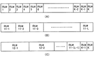
本実施形態では、複数の端末から基地局にアップリンクOFDMA(UL−OFDMA:Orthogonal Frequency Division Multiple Access)送信を行う場合を想定する。UL−OFDMAでは、1つまたは複数のサブキャリアをリソースユニット(サブチャネル、リソースブロック、周波数ブロックなどと呼んでもよい)として端末に割り当て、リソースユニットベースで、複数の端末からの受信を同時に行う。リソースユニットは、通信を行うリソースの最小単位となる周波数成分である。図3に、1つのチャネル(ここではチャネルMと記述している)の連続した周波数領域内に確保したリソースユニット(RU#1、RU#2、・・・RU#K)を示す。チャネルMには、互いに直交する複数のサブキャリアが配置されており、1つまたは複数の連続するサブキャリアを含む複数のリソースユニットがチャネルM内に定義されている。リソースユニット間には、1つ以上のサブキャリア(ガードサブキャリア)が配置されてもよいが、ガードサブキャリアは必須ではない。チャネル内の各サブキャリアには、サブキャリアを識別するための番号が付与されていてもよい。1つのチャネルの帯域幅は、一例として、20MHz、40MHz、80MHz、160MHzなどであるが、これらに限定されない。20MHzの複数のチャネルをまとめて1つのチャネルとしてもよい。帯域幅に応じてチャネル内のサブキャリア数またはリソースユニット数が異なってもよい。複数の端末がそれぞれ異なるリソースユニットを同時に用いることで、アップリンクOFDMA通信が実現される。
In the present embodiment, it is assumed that a plurality of terminals perform uplink OFDMA (UL-OFDMA: Orthogonal Frequency Division Multiple Access) transmission. In UL-OFDMA, one or more subcarriers are assigned to terminals as resource units (may be called subchannels, resource blocks, frequency blocks, etc.), and reception from a plurality of terminals is performed simultaneously on a resource unit basis. The resource unit is a frequency component that is the minimum unit of resources for communication. FIG. 3 shows resource units (
リソースユニットの帯域幅(あるいはサブキャリア数)は、各リソースユニットで共通でもよいし、リソースユニットごとに帯域幅(あるいはサブキャリア数)が異なってもよい。図3に、1つのチャネル内におけるリソースユニットの配置パターン例を模式的に示す。紙面に沿って横方向が周波数領域方向に対応する。図3(A)は、同じ帯域幅の複数のリソースユニット(RU#1、RU#2、・・・RU#K)を配置した例を示し。図3(B)は、図3(A)より大きな帯域幅の複数のリソースユニット(RU#11−1、RU#11−2、・・・、RU#11−L)を配置した例を示す。図3(C)は3種類の帯域幅のリソースユニットを配置した例を示す。リソースユニット(RU#12−1、RU#12−2)が最も大きな帯域幅を有し、リソースユニットRU#12−(L−1)は図3(B)と同じ帯域幅、リソースユニット(RU#K−1、RU#K)は図3(A)と同じ帯域幅である。
The bandwidth (or the number of subcarriers) of the resource unit may be common to each resource unit, or the bandwidth (or the number of subcarriers) may be different for each resource unit. FIG. 3 schematically shows an arrangement pattern example of resource units in one channel. The horizontal direction along the paper corresponds to the frequency domain direction. FIG. 3A shows an example in which a plurality of resource units (
具体例を示す。20MHzチャネル幅全体を使う場合、20MHzチャネル幅内に配置される256サブキャリア(トーン)に対し、リソースユニットが26個(トーン)設定できる。つまり、20MHzチャネル幅では9つのリソースユニットが設定され、リソースユニットの帯域幅としては2.5MHz幅より小さくなる。40MHzチャネル幅では、リソースユニットは18個設定される。80MHzチャネル幅では37個設定される(doc.:IEEE 802.11−15/0330r5参照)。これを発展させると、例えば160MHzチャネル幅または80+80MHzチャネル幅では、74個のリソースユニットが設定される。もちろんリソースユニットの幅は特定の値に制限されず、様々なサイズのリソースユニットを配置することもできる。 A specific example is shown. When using the entire 20 MHz channel width, 26 resource units (tones) can be set for 256 subcarriers (tones) arranged in the 20 MHz channel width. That is, 9 resource units are set in the 20 MHz channel width, and the bandwidth of the resource unit is smaller than the 2.5 MHz width. In the 40 MHz channel width, 18 resource units are set. 37 pieces are set in the 80 MHz channel width (see doc.: IEEE 802.11-15/0330r5). When this is developed, for example, in a 160 MHz channel width or an 80+80 MHz channel width, 74 resource units are set. Of course, the width of the resource unit is not limited to a specific value, and resource units of various sizes can be arranged.
なお、各端末が使用するリソースユニット数は、特定の値に制限されず、1つまたは複数のリソースユニットを用いてもよい。端末が複数のリソースユニットを用いる場合、周波数的に連続する複数のリソースユニットを用いてもよいし、離れた箇所にある複数のリソースユニットを用いることを許容してもよい。 The number of resource units used by each terminal is not limited to a specific value, and one or a plurality of resource units may be used. When the terminal uses a plurality of resource units, a plurality of resource units that are consecutive in frequency may be used, or a plurality of resource units that are distant may be used.
1つのリソースユニット内のサブキャリアは周波数領域で連続しているとするが、非連続に配置された複数のサブキャリアからリソースユニットを定義してもよい。アップリンクOFDMA通信で使用するチャネルは1つに限定されず、チャネルMと周波数領域で離れた位置に配置された別のチャネル(図2ではチャネルNを参照)内にも、チャネルMと同様にしてリソースユニットを確保し、チャネルMとチャネルNの両方内のリソースユニットを用いてもよい。チャネルMとチャネルNとでリソースユニットの配置方法は同じであっても、異なってもよい。チャネルNの帯域幅は、一例として、上述のように、20MHz、40MHz、80MHz、160MHzなどであるが、これらに限定されない。3つ以上のチャネルを用いることも可能である。なお、チャネルMとチャネルNをまとめて1つのチャネルとして考えても良い。 It is assumed that the subcarriers in one resource unit are continuous in the frequency domain, but the resource unit may be defined by a plurality of subcarriers arranged discontinuously. The number of channels used in the uplink OFDMA communication is not limited to one, and the same as the case of the channel M in another channel (see the channel N in FIG. 2) located at a position separated from the channel M in the frequency domain. The resource unit may be reserved by using the resource unit in both the channel M and the channel N. The method of arranging the resource units in the channel M and the channel N may be the same or different. The bandwidth of the channel N is, for example, 20 MHz, 40 MHz, 80 MHz, 160 MHz, etc. as described above, but is not limited thereto. It is also possible to use more than two channels. The channel M and the channel N may be collectively considered as one channel.
なお、OFDMAを実施する端末は、少なくとも後方互換の対象となるレガシー端末での基本チャネル幅(IEEE802.11a/b/g/n/ac規格対応端末をレガシー端末とするなら20MHzチャネル幅)のチャネルで、フレームを含む物理パケットを受信・復号(復調および誤り訂正符号の復号等を含む)できるものとする。キャリアセンスに関しては基本チャネル幅の単位で行うものとする。キャリアセンスは、CCA(Clear Channel Assessment)のビジー/アイドルに関する物理的なキャリアセンス(Physical Carrier Sense)と、受信したフレームの中に記載されている媒体予約時間に基づく仮想的なキャリアセンス(Virtual Carrier Sense)との両方を包含してもよい。後者のように、仮想的に媒体をビジーであると判定する仕組み、或いは、仮想的に媒体をビジーであるとする期間は、NAV(Network Allocation Vector)と呼ばれる。なお、チャネル単位で行ったCCAまたはNAVに基づくキャリアセンス情報は、チャネル内の全リソースユニットに共通に適用してもよい。例えばキャリアセンス情報がアイドルを示すチャネルに属するリソースユニットはすべてアイドルである。 Note that the terminal that implements OFDMA has at least a channel with a basic channel width (20 MHz channel width if a terminal compatible with the IEEE802.11a/b/g/n/ac standard is a legacy terminal) in a legacy terminal that is a backward compatibility target. Then, a physical packet including a frame can be received and decoded (including demodulation and decoding of error correction code). Carrier sense is performed in units of the basic channel width. The carrier sense is a physical carrier sense (Physical Carrier Sense) regarding busy/idle of CCA (Clear Channel Assessment), and a virtual carrier sense (Virtual Carrier) based on the medium reservation time described in the received frame. Sense) may be included. A mechanism for determining that a medium is virtually busy like the latter, or a period during which a medium is virtually busy is called NAV (Network Allocation Vector). The carrier sense information based on CCA or NAV performed on a channel-by-channel basis may be commonly applied to all resource units in the channel. For example, all resource units belonging to a channel whose carrier sense information indicates idle are idle.
なお、OFDMAは上述したリソースユニットベースのOFDMA以外に、チャネルベースでのOFDMAも可能である。この場合のOFDMAを特にMU−MC(Multi−User Multi−Channel)と呼ぶことがある。MU−MCでは、基地局が複数のチャネル(1つのチャネル幅は例えば20MHzなど)を複数の端末に割り当て、当該複数のチャネルを同時に用いて、複数端末宛て同時送信もしくは複数端末からの同時受信を行う。以降に説明するOFDMAでは、リソースユニットベースのOFDMAを想定するが、以降の説明のリソースユニットをチャネルに読み替えるなど、必要な読み替えを行うことで、チャネルベースのOFDMAの実施形態も実現可能である。 Note that OFDMA can be channel-based OFDMA in addition to the resource unit-based OFDMA described above. The OFDMA in this case may be particularly referred to as MU-MC (Multi-User Multi-Channel). In MU-MC, a base station allocates a plurality of channels (one channel width is, for example, 20 MHz) to a plurality of terminals and simultaneously uses the plurality of channels to perform simultaneous transmission to or reception from a plurality of terminals. To do. In OFDMA described below, a resource unit-based OFDMA is assumed, but an embodiment of channel-based OFDMA can also be realized by performing necessary reading such as replacing the resource unit in the following description with a channel.
なお、複数の端末から基地局へのアップリンク多重送信では、上述したOFDMA以外に、OFDMAとMU−MIMO(Multiple−Input Multiple−Output)を組み合わせた通信方式(OFDMA&MU−MIMOと呼ぶ)も可能である。アップリンクMU−MIMO送信は、複数の端末から基地局に空間多重で(同一周波数帯域で同時に)ストリームを送信し、基地局が複数のアンテナでこれらストリームを同時に受信するものである。OFDMA&MU−MIMOの場合、複数の端末が同じリソースユニットを利用して、MU−MIMO送信を行うことになる。以降の説明でOFDMAを指すときは、OFDMA&MU−MIMOでもよいものとする。 In addition, in uplink multiplex transmission from a plurality of terminals to a base station, in addition to OFDMA described above, a communication method (referred to as OFDMA & MU-MIMO) that combines OFDMA and MU-MIMO (Multiple-Input Multiple-Output) is also possible. is there. Uplink MU-MIMO transmission is a method in which a plurality of terminals transmit streams to a base station by spatial multiplexing (simultaneously in the same frequency band), and the base station simultaneously receives these streams by a plurality of antennas. In the case of OFDMA & MU-MIMO, a plurality of terminals use the same resource unit to perform MU-MIMO transmission. In the following description, when referring to OFDMA, OFDMA & MU-MIMO may be used.
以下の説明において、UL−OFDMAを実施する能力を有する端末をUL−OFDMA対応端末(あるいは単純にOFDMA対応端末)などと呼ぶことがある。当該能力を有さない端末をレガシー端末と呼ぶことがある。UL−OFDMA通信を実施する能力を有効(Enable)または無効(Disable)に切り替え可能な場合、当該能力が有効になっている端末をOFDMA対応端末として考えればよい。 In the following description, a terminal capable of implementing UL-OFDMA may be referred to as a UL-OFDMA compatible terminal (or simply an OFDMA compatible terminal) or the like. A terminal that does not have the capability may be called a legacy terminal. When the ability to carry out UL-OFDMA communication can be switched to valid (Enable) or invalid (Disable), the terminal in which the relevant ability is valid may be considered as an OFDMA-compatible terminal.
図1に示されるように、端末(非基地局の端末及び基地局)に搭載される無線通信装置は、上位処理部90、MAC処理部10、PHY(Physical:物理)処理部50、MAC/PHY管理部60、アナログ処理部70(アナログ処理部1〜N)及びアンテナ80(アンテナ1〜N)を含む。Nは1以上の整数である。図では、N個のアナログ処理部と、N個のアンテナが、一対ずつ接続されているが、必ずしもこの構成に限定されるものではない。例えばアナログ処理部の個数が1つで、2つ以上のアンテナがこのアナログ処理部に共通に接続されてもよい。
As shown in FIG. 1, the wireless communication device mounted on a terminal (a terminal of a non-base station and a base station) includes a high-
MAC処理部10、MAC/PHY管理部60、及びPHY処理部50は、他の端末(基地局を含む)との通信に関する処理を行う制御部またはベースバンド集積回路の一形態に相当する。アナログ処理部70は、例えばアンテナ80を介して信号を送受信する無線通信部またはRF(Radio Frequency)集積回路の一形態に相当する。本実施形態に係る無線通信用集積回路は、当該ベースバンド集積回路(制御部)およびRF集積回路の少なくとも前者を含む。通信処理装置またはベースバンド集積回路の機能は、CPU等のプロセッサで動作するソフトウェア(プログラム)によって行われてもよいし、ハードウェアによって行われてもよいし、ソフトウェアとハードウェアの両方によって行われてもよい。ソフトウェアはROM、RAM等のメモリ、ハードディスク、SSDなどの記憶媒体に格納してプロセッサにより読み出して実行してもよい。メモリはSRAM、DRAM等の揮発性メモリでも、NAND、MRAM等の不揮発性メモリでもよい。
The
上位処理部90は、MAC(Medium Access Control:媒体アクセス制御)層に対して上位層のための処理を行う。上位処理部90は、MAC処理部10との間で信号をやり取りできる。上位層としては、代表的なものとしては、TCP/IPやUDP/IP、さらにその上層のアプリケーション層などが挙げられるが、本実施形態はこれに限定されない。上位処理部90は、MAC層と上位層との間でデータをやり取りするためのバッファを備えていてもよい。上位処理部90を介して有線インフラに接続するようになっていてもよい。バッファは、メモリでもよいし、SSD、ハードディスク等でもよい。バッファがメモリの場合、当該メモリはSRAM、DRAM等の揮発性メモリでも、NAND、MRAM等の不揮発性メモリでもよい。
The
MAC処理部10は、MAC層のための処理を行う。前述のように、MAC処理部10は、上位処理部90との間で信号をやり取りできる。更に、MAC処理部10は、PHY処理部50との間で、信号をやり取りできる。MAC処理部10は、MAC共通処理部20と送信処理部30と受信処理部40を含む。
The
MAC共通処理部20は、MAC層での送受信に共通する処理を行う。MAC共通処理部20は、上位処理部90、送信処理部30、受信処理部40及びMAC/PHY管理部60と接続され、夫々との間で信号のやり取りをする。
The MAC
送信処理部30及び受信処理部40は、相互に接続している。また、送信処理部30及び受信処理部40は、それぞれMAC共通処理部20及びPHY処理部50に接続している。送信処理部30は、MAC層での送信処理を行う。受信処理部40は、MAC層での受信処理を行う。
The
PHY処理部50は、物理層(PHY層)のための処理を行う。前述のように、PHY処理部50は、MAC処理部10との間で信号をやり取りできる。PHY処理部50は、アナログ処理部70を介してアンテナ80に接続されている。
The
MAC/PHY管理部60は、上位処理部90、MAC処理部10(より詳細には、MAC共通処理部20)及びPHY処理部50の夫々と接続されている。MAC/PHY管理部60は、無線通信装置におけるMAC動作及びPHY動作を管理する。
The MAC/
アナログ処理部70は、アナログ/デジタル及びデジタル/アナログ(AD/DA)変換器およびRF(Radio Frequency)回路を含み、PHY処理部50からのデジタル信号を所望の周波数のアナログ信号に変換してアンテナ80から送信、またアンテナ80から受信した高周波のアナログ信号をデジタル信号に変換する。なお、ここでは、AD/DA変換をアナログ処理部70で行っているが、PHY処理部50にAD/DA変換機能を持たせる構成も可能である。
The
本実施形態に係る無線通信装置は、1チップ内にアンテナ80を構成要素として含む(一体化する)ことで、このアンテナ80の実装面積を小さく抑えることができる。更に、本実施形態に係る無線通信装置は、図1に示されるように、送信処理部30及び受信処理部40が、N本のアンテナ80を共用している。送信処理部30及び受信処理部40がN本のアンテナ80を共用することにより、図1の無線通信装置を小型化できる。なお、本実施形態に係る無線通信装置は、図1に例示されたものと異なる構成を備えても勿論よい。
The wireless communication device according to the present embodiment can suppress the mounting area of the
無線媒体からの信号受信に際して、アナログ処理部70は、アンテナ80が受信したアナログ信号を、PHY処理部50が処理可能な基底帯域(Baseband)の信号に変換し、さらにデジタル信号に変換する。PHY処理部50は、アナログ処理部70からデジタルの受信信号を受け取り、その受信レベルを検出する。検出した受信レベルを、キャリアセンスレベル(閾値)と比較し、受信レベルが、キャリアセンスレベル以上であれば、PHY処理部50は媒体(CCA:Clear Channel Assessment)がビジーであるということを示す信号を、MAC処理部10(より正確には、受信処理部40)へ出力する。受信レベルが、キャリアセンスレベル未満であれば、PHY処理部50は、媒体(CCA)がアイドルであるということを示す信号を、MAC処理部10(より正確には受信処理部40)へ出力する。
When receiving a signal from the wireless medium, the
PHY処理部50は、受信信号に対し、復号(復調および誤り訂正符号の復号等を含む)処理、プリアンブルを含む物理ヘッダ(PHYヘッダ)を取り除く処理などを行って、ペイロードを抽出する。IEEE802.11規格ではこのペイロードをPHY側ではPSDU(physical layer convergence procedure (PLCP) service data unit)と呼んでいる。PHY処理部50は、抽出したペイロードを受信処理部40に渡し、受信処理部40はこれをMACフレームとして扱う。IEEE802.11規格では、このMACフレームを、MPDU(medium access control (MAC) protocol data unit)と呼んでいる。加えて、PHY処理部50は、受信信号を受信開始した際に、その旨を受信処理部40に通知し、また受信信号を受信終了した際に、その旨を受信処理部40に通知する。また、PHY処理部50は、受信信号が正常に物理パケット(PHYパケット)として復号できた場合(エラーを検出しなければ)、受信信号の受信終了を通知すると共に、媒体がアイドルであるということを示す信号を、受信処理部40に渡す。PHY処理部50は、受信信号にエラーを検出した場合には、エラー種別に即した適切なエラーコードをもって、受信処理部40にエラーを検出したことを通知する。また、PHY処理部50は、媒体がアイドルになったと判定した時点で、媒体がアイドルであることを示す信号を受信処理部40に通知する。
The
MAC共通処理部20は、上位処理部90から送信処理部30への送信データの受け渡し、及び受信処理部40から上位処理部90への受信データの受け渡しを、夫々仲介する。IEEE802.11規格では、このMACデータフレームの中のデータを、MSDU(medium access control (MAC) service data unit)と呼んでいる。また、MAC共通処理部20は、MAC/PHY管理部60からの指示を一旦受け取り、当該指示を送信処理部30及び受信処理部40に、それぞれ適したものに変換して出力する。
The MAC
MAC/PHY管理部60は、例えばIEEE802.11規格におけるSME(Station Management Entity)に相当する。その場合、MAC/PHY管理部60とMAC共通処理部20との間のインタフェースは、IEEE802.11規格におけるMLME SAP(MAC subLayer Managament Entity Service Access Point)に相当し、MAC/PHY管理部60とPHY処理部50との間のインタフェースは、IEEE802.11無線LAN(Local Area Network)におけるPLME SAP(Physical Layer Management Entity Service Access Point)に相当する。
The MAC/
なお、図1において、MAC/PHY管理部60は、MAC管理のための機能部とPHY管理のための機能部とが一体であるかのように描かれているが、分けて実装されてもよい。
In addition, in FIG. 1, the MAC/
MAC/PHY管理部60は、管理情報ベース(Management Information Base:MIB)を保持する。MIBは、自端末の能力や各種機能が夫々有効か無効かなどの各種情報を保持する。例えば、自端末が、UL−OFDMA対応か否か、また、UL−OFDMA対応の場合にUL−OFDMAを実施する能力の機能のオン/オフの情報も保持されていてもよい。MIBを保持・管理するためのメモリは、MAC/PHY管理部60に内包させてもよいし、MAC/PHY管理部60に内包せずに別に設けるようにしてもよい。MIBを保持・管理するためのメモリをMAC/PHY管理部60とは別に設ける場合に、MAC/PHY管理部60は、その別のメモリを参照でき、またメモリ内の書き換え可能なパラメータに関しては書き換えを行うことができる。メモリはSRAM、DRAM等の揮発性メモリでも、NAND、MRAM等の不揮発メモリでもよい。また、メモリでなく、SSDやハードディスク等の記憶装置でもよい。基地局では、非基地局としての他の端末のこれらの情報も、当該端末からの通知により、取得することができる。その場合、MAC/PHY管理部60は、他の端末に関する情報を参照・書き換えが可能になっている。あるいはこれらの他の端末に関する情報を記憶するためのメモリは、MIBとは別に保持・管理するようにしてもよい。その場合、MAC/PHY管理部60あるいはMAC共通処理部20が、その別のメモリを参照・書き換えが可能なようにする。また基地局のMAC/PHY管理部60は、UL−OFDMAの実施にあたり、非基地局としての端末に関する各種の情報、または端末からの要求に基づき、UL−OFDMA用のリソースユニットを同時に割り当てる端末を選定する(すなわち今回のUL−OFDMAの対象となる端末を選定する)選定機能も備えていてもよい。また、MAC/PHY管理部60またはMAC処理部10は、送信するMACフレームおよび物理ヘッダに適用する伝送レートを管理してもよい。また基地局のMAC/PHY管理部60は、基地局がサポートするレートセットであるサポートレートセットを定義および管理してもよい。サポートレートセットは、基地局に接続する端末がサポートすることが必須であるレートと、オプションのレートを含んでもよい。
The MAC/
MAC処理部10は、データフレーム、制御フレーム及び管理フレームの3種類のMACフレームを扱い、MAC層において規定される各種処理を行う。ここで、3種類のMACフレームについて説明する。
The
管理フレームは、他の端末との間の通信リンクの管理のために用いられる。管理フレームとしては、例えば、IEEE802.11規格におけるBasic Service Set(BSS)である無線通信グループを形成するために、グループの属性及び同期情報を報知するビーコン(Beacon)フレームがある。また、認証のためにまたは通信リンク確立のために交換されるフレームなどもある。なお、ある端末が、もう一台の端末と互いに無線通信を実施するために必要な情報交換を済ませた状態を、通信リンクが確立していると、ここでは表現する。必要な情報交換として、例えば、自端末が対応する機能(例えばUL−OFDMA方式への対応や後述する各種能力など)の通知や、方式の設定に関するネゴシエーションなどがある。管理フレームは、送信処理部30が、MAC/PHY管理部60からMAC共通処理部20を介して受けた指示に基づいて生成する。
The management frame is used for managing a communication link with another terminal. As the management frame, for example, there is a beacon frame which notifies group attribute and synchronization information in order to form a wireless communication group which is a Basic Service Set (BSS) in the IEEE 802.11 standard. There are also frames etc. exchanged for authentication or for establishing communication links. In addition, a state in which a certain terminal has exchanged information necessary for performing wireless communication with another terminal is referred to as a communication link established here. Necessary information exchange includes, for example, notification of functions supported by the terminal itself (for example, support for UL-OFDMA system, various capabilities described later, etc.), negotiation for system setting, and the like. The management frame is generated by the
管理フレームに関連して、送信処理部30は、他の端末に管理フレームを介して各種情報を通知する通知手段を有する。非基地局としての端末の通知手段は、UL−OFDMA対応端末、IEEE802.11n対応端末、IEEE802.11ac対応端末のいずれに対応しているかの情報を、管理フレームに入れて送信することで、基地局に自端末の種別を通知してもよい。この管理フレームとしては、例えば端末が基地局との間で認証を行う手順の一つであるアソシエーションプロセスで用いられるAssociation Requestフレームや、あるいはリアエソシエーションプロセスで用いられるReassociation Requestフレームがある。基地局の通知手段は、非基地局の端末に、UL−OFDMA通信への対応可否の情報を、管理フレームを介して通知してもよい。これに用いる管理フレームとしては、例えばBeaconフレームや、非基地局端末が送信したProbe Requestフレームに対する応答であるProbe Responseフレームがある。基地局は、自装置に接続している端末群をグループ化する機能を有していてもよい。基地局の上記の通知手段は、各端末にそれぞれが属するグループのグループ識別子であるグループIDを、管理フレームを介して通知してもよい。この管理フレームとしては、例えばGroup ID Managementフレームがある。グループIDは、例えばIEEE Std 802.11ac−2013でDL−MU−MIMOのために規定されたグループID(6ビット)をUL−OFDMAの場合も包含するように拡張したものでもよいし、これとは別の方法で定義したグループIDでもよい。また、基地局は、当該グループを指定してUL−OFDMAをする場合に、当該グループに属する端末が使用するリソースユニットを決定するために必要な情報が存在すれば、任意の管理フレームを介して通知してもよい(後述するようにグループを指定する場合、端末はランダムバックオフ手法に類似した方法に基づきリソースユニットを選択する機能を備える)。
In relation to the management frame, the
ここでアソシエーションID(AID)について説明する。AIDは、端末が基地局に接続し、基地局下のBSSでデータフレーム交換が行えるようにするためのアソシエーションプロセスで、基地局から割り当てられる端末の識別子(端末識別子)である。アソシエーションプロセスは具体的には、端末から基地局宛てにAssociation Requestフレームを送信し、基地局から端末宛てにAssociation Responseフレームを送信し、Association Responseフレームの中の端末Status Codeフィールドが”0”すなわちsuccessである場合に成功するプロセスである。Association Requestフレーム、Association Responseフレームの双方には、送信端末の通信能力(Capability)が入れられており、それにより、受信した双方が相手の通信能力を把握する。Association Responseフレームの中の端末Status Codeフィールドが”0”すなわちsuccessである場合には、同フレーム中のAIDフィールド(16ビット)からAIDを抽出し、送信先端末のAIDとして使われることになる。すなわち、この時点で、基地局から端末にAIDが割り当てられたことになり、端末としてはAIDが有効の状態となる。当該基地局が端末との間で接続(Association)している状態では、端末のAIDが有効である。一方、基地局から当該端末にDisassociationフレームを送信し、当該端末が受信すると、あるいは当該端末から基地局にDisassociationフレームを送信すると、当該端末のAIDは無効(null)となる。どの基地局ともアソシエーションプロセスを経ていない状態の端末でも当然、AIDは無効である。AIDが無効の状態は、AIDが未指定の状態とも言うこともできる。 Here, the association ID (AID) will be described. The AID is an association process (terminal identifier) of the terminal assigned from the base station in an association process for allowing the terminal to connect to the base station and exchange data frames in the BSS under the base station. Specifically, the association process transmits an Association Request frame from the terminal to the base station, transmits an Association Response frame from the base station to the terminal, and sets the terminal Status Code field in the Association Response frame to “0”, that is, success. Is a successful process. The communication capability (Capability) of the transmitting terminal is included in both the Association Request frame and the Association Response frame, so that both of the receiving sides know the communication capability of the other party. When the terminal Status Code field in the Association Response frame is “0”, that is, success, the AID is extracted from the AID field (16 bits) in the same frame and used as the AID of the destination terminal. That is, at this point, the base station has assigned the AID to the terminal, and the AID is valid for the terminal. The AID of the terminal is valid in the state where the base station is connected (associated) with the terminal. On the other hand, when the base station transmits a Disassociation frame to the terminal and the terminal receives the Disassociation frame, or when the terminal transmits a Disassociation frame to the base station, the AID of the terminal becomes null. Naturally, the AID is invalid even in a terminal that has not gone through an association process with any base station. The state in which the AID is invalid can also be called a state in which the AID is unspecified.
受信処理部40は、他の端末から管理フレームを介して各種情報を受信する受信手段を有する。一例として、基地局の受信手段は、非基地局としての端末からUL−OFDMA通信への対応可否の情報を受信してもよい。また、当該端末がレガシー端末(IEEE802.11a/b/g/n/ac規格対応端末など)の場合に対応可能なチャネル幅(利用可能な最大のチャネル幅)の情報を受信してもよい。端末の受信手段は、基地局からUL−OFDMAサポートの対応可否の情報を受信してもよい。
The
上述した管理フレームを介して送受信する情報の例は、ほんの一例であり、その他種々の情報を、管理フレームを介して、端末(基地局を含む)間で送受信することが可能である。例えばUL−OFDMA対応端末は、自身がUL−OFDMA送信で使用することを希望するリソースユニット、または、チャネル、またはこれらの両方を、キャリアセンスで非干渉のチャネル、または、非干渉のリソースユニット、またはこれらの両方から、選択してもよい。そして、選択したリソースユニットまたはチャネルまたはこれらの両方に関する情報を、基地局に通知してもよい。この場合、基地局は当該情報に基づき、UL−OFDMA通信のためのリソースユニット割り当てを各UL−OFDMA対応端末に対して行ってもよい。なお、UL−OFDMA通信で利用するチャネルは、無線通信システムとして利用可能な全てのチャネルであっても、一部(1つまたは複数)のチャネルであってもよい。 The example of the information transmitted/received via the management frame described above is only an example, and various other information can be transmitted/received between terminals (including a base station) via the management frame. For example, a UL-OFDMA-capable terminal uses a resource unit or a channel, or both of which it desires to use in UL-OFDMA transmission, with a carrier-sense non-interfering channel or non-interfering resource unit, Alternatively, both of them may be selected. Then, the base station may be notified of information regarding the selected resource unit and/or channel. In this case, the base station may perform resource unit allocation for UL-OFDMA communication to each UL-OFDMA compatible terminal based on the information. Note that the channels used in UL-OFDMA communication may be all channels that can be used as a wireless communication system or some (one or more) channels.
データフレームは、他の端末との間で通信リンクが確立した状態で、データを当該他の端末に送信するために用いられる。例えばユーザのアプリケーション操作によって、端末においてデータが生成され、当該データがデータフレームによって搬送される。具体的には、生成されたデータは、上位処理部90からMAC共通処理部20を介して送信処理部30に渡され、送信処理部30でデータをフレームボディフィールドに入れ、当該フレームボディフィールドにMACヘッダを付加してデータフレームが生成される。そして、PHY処理部50で、データフレームに物理ヘッダを付加して物理パケットが生成され、物理パケットが、アナログ処理部70及びアンテナ80を介して送信される。また、PHY処理部50で物理パケットを受信すると、物理ヘッダに基づき物理層の処理を行ってMACフレーム(ここではデータフレーム)を抽出し、データフレームを受信処理部40に渡す。受信処理部40は、データフレームを受けると(受信したMACフレームがデータフレームであると把握すると)、そのフレームボディフィールドの情報をデータとして抽出し、抽出したデータを、MAC共通処理部20を介して上位処理部90に渡す。この結果、データの書き込み、再生などのアプリケーション上の動作が生じる。
The data frame is used to transmit data to the other terminal while the communication link is established with the other terminal. For example, data is generated in the terminal by the application operation of the user, and the data is carried by the data frame. Specifically, the generated data is passed from the higher-
制御フレームは、管理フレーム及びデータフレームを、他の無線通信装置との間で送受信(交換)するときの制御のために用いられる。制御フレームとしては、例えば、管理フレーム及びデータフレームの交換を開始する前に、無線媒体を予約するために他の無線通信装置との間で交換するRTS(Request to Send)フレーム、CTS(Clear to Send)フレームなどがある。また、他の制御フレームとして、受信した管理フレーム及びデータフレームの送達確認のための送達確認応答フレームがある。送達確認応答フレームの例として、ACK(Acknowledgement)フレーム、BA(BlockACK)フレームなどがある。CTSフレームも、RTSフレームの応答として送信するため、送達確認応答を表すフレームであるとも言える。CF−Endフレームも、制御フレームの1つである。CF−Endフレームは、CFP(Contention Free Period)の終了あるいは後述のTXOPの打切りをアナウンスするフレーム、つまり、無線媒体へのアクセスを許可するフレームである。これらの制御フレームは送信処理部30で生成される。受信したMACフレームへの応答として送信される制御フレーム(CTSフレームやACKフレーム、BAフレームなど)に関しては、受信処理部40で応答フレーム(制御フレーム)の送信の必要を判断して、フレーム生成に必要な情報(制御フレームの種別、RA(Receiver Address)フィールド等に設定する情報など)を送信指示とともに送信処理部30に出す。送信処理部30は、当該フレーム生成に必要な情報と送信指示に基づき、適切な制御フレームを生成する。
The control frame is used for control when transmitting/receiving (exchange) the management frame and the data frame to/from another wireless communication device. As the control frame, for example, an RTS (Request to Send) frame and a CTS (Clear to send) that are exchanged with another wireless communication device to reserve a wireless medium before the exchange of a management frame and a data frame is started. Send) frame. Further, as another control frame, there is a delivery confirmation response frame for confirming delivery of the received management frame and data frame. Examples of the delivery confirmation response frame include an ACK (Acknowledgement) frame and a BA (BlockACK) frame. Since the CTS frame is also transmitted as a response to the RTS frame, it can be said that the frame also represents a delivery confirmation response. The CF-End frame is also one of the control frames. The CF-End frame is a frame that announces the end of CFP (Contention Free Period) or the termination of TXOP described later, that is, a frame that permits access to a wireless medium. These control frames are generated by the
MAC処理部10は、CSMA/CA(Carrier Sense Multiple Access with Carrier Avoidance)に基づきMACフレームを送信する場合、無線媒体上でのアクセス権(送信権)を獲得する必要がある。送信処理部30は、受信処理部40からのキャリアセンス情報に基づいて、送信タイミングを計る。送信処理部30は、係る送信タイミングに従って、PHY処理部50に送信指示を与えて、さらにMACフレームを渡す。送信指示に加えて、送信処理部30は、送信に使用される変調方式及び符号化方式を合わせて指示してもよい。これらに加えて、送信処理部30は、送信電力を指示してもよい。MAC処理部10は、アクセス権(送信権)獲得後、媒体を占有可能な時間(Transmission Opportunity;TXOP)が得られると、QoS(Quality of Service)属性などの制限を伴うものの、他の無線通信装置との間でMACフレームを連続して交換できる。TXOPは、例えば、無線通信装置がCSMA/CA(Carrier Sense Multiple Access with Carrier Avoidance)に基づき所定のフレーム(例えばRTSフレーム)を送信し、他の無線通信装置から応答フレーム(例えばCTSフレーム)を正しく受信した場合に、獲得される。この所定のフレームが、当該他の無線通信装置によって受信されると、当該他の無線通信装置は、最小フレーム間隔(Short InterFrame Space;SIFS)後に、上記応答フレームを送信する。また、RTSフレームを用いないでTXOPを獲得する方法として、例えば直接ユニキャストで、送達確認応答フレームの送信を要求するデータフレーム(後述のようにフレームが連接された形状のフレーム、またはペイロードが連接された形状のフレームであってもよい)あるいは管理フレームを送信し、それに対する送達確認応答フレーム(ACKフレームやBlockACKフレーム)を正しく受信する場合がある。あるいは、他の無線通信装置に送達確認応答フレームの送信を要求しないフレームであって、そのフレームのDuration/IDフィールドに当該フレームの送信に要する時間以上の期間を設定したものを送信した場合には、当該フレームを送信した段階からDuration/IDフィールドに記載された期間のTXOPを獲得したと解釈してもよい。
When transmitting a MAC frame based on CSMA/CA (Carrier Sense Multiple Access with Carrier Aviation), the
受信処理部40は、上述したキャリアセンス情報を管理する。このキャリアセンス情報は、PHY処理部50から入力される媒体(CCA)のビジー/アイドルに関する物理的なキャリアセンス(Physical Carrier Sense)情報と、受信フレームの中に記載されている媒体予約時間に基づく仮想的なキャリアセンス(Virtual Carrier Sense)情報との両方を包含する。いずれか一方のキャリアセンス情報がビジーを示すならば、媒体がビジーであるとみなされ、その間送信は禁止される。なお、IEEE802.11規格において、媒体予約時間は、MACヘッダの中のDuration/IDフィールドに記載される。MAC処理部10は、他の無線通信装置宛ての(自己宛てでない)MACフレームを受信した場合に、当該MACフレームを含む物理パケットの終わりから媒体予約時間に亘って、媒体が仮想的にビジーであると判定する。このような仮想的に媒体をビジーであると判定する仕組み、或いは、仮想的に媒体をビジーであるとする期間は、NAV(Network Allocation Vector)と呼ばれる。媒体予約時間は無線媒体へのアクセスの抑制を指示する期間の長さ、すなわち無線媒体へのアクセスを延期させる期間の長さを表しているといえる。
The
ここで、MPDUは、複数のMACフレームもしくは複数のMACフレームのペイロード部分を連接するようになっていてもよい。前者はIEEE802.11規格ではA(Aggregated)−MPDU、後者はA(Aggregated)−MSDU(MAC service data unit)と呼ばれる。A−MPDUの場合は、PSDUの中に複数のMPDUが連接されることになる。またMACフレームとしてはデータフレームのみならず、管理フレームや制御フレームも連接対象となる。A−MSDUの場合には、1つのMPDUのフレームボディ中に、複数のデータペイロードであるMSDUが連接されることになる。A−MPDU、およびA−MSDUのいずれも、複数のMPDUの連接、および複数のMSDUの連接を、受信側端末で適切に分離できるように、フレームに区切り情報(長さ情報など)が格納されている。A−MPDUおよびA−MSDUの両方を組み合わせて用いてもよい。またA−MPDUは、複数のMACフレームではなく、1つのMACフレームのみを対象としてもよく、この場合も区切り情報をフレームに格納する。また、A−MPDUなどを受信した場合は、連接されている複数のMACフレームに対する応答をまとめて送信する。この場合の応答には、ACKフレームではなく、BA(BlockACK)フレームが用いられる。以降の説明および図では、MPDUの表記を用いることがあるが、これは、上述したA−MPDUまたはA−MSDUの場合も含むものとする。 Here, the MPDU may connect a plurality of MAC frames or payload portions of a plurality of MAC frames. The former is called A (Aggregated)-MPDU in the IEEE 802.11 standard, and the latter is called A (Aggregated)-MSDU (MAC service data unit). In the case of A-MPDU, a plurality of MPDUs are connected in PSDU. As the MAC frame, not only the data frame but also the management frame and the control frame are connected. In the case of A-MSDU, a plurality of data payloads MSDUs are concatenated in the frame body of one MPDU. Both A-MPDU and A-MSDU store delimiter information (length information, etc.) in a frame so that the receiving terminal can appropriately separate the connection of a plurality of MPDUs and the connection of a plurality of MSDUs. ing. Both A-MPDU and A-MSDU may be used in combination. Further, the A-MPDU may target only one MAC frame instead of a plurality of MAC frames, and in this case also, delimiter information is stored in the frame. Further, when receiving A-MPDU or the like, responses to a plurality of concatenated MAC frames are collectively transmitted. In this case, a BA (BlockACK) frame is used for the response instead of the ACK frame. In the following description and drawings, the notation of MPDU may be used, but this also includes the case of A-MPDU or A-MSDU described above.
IEEE802.11規格では、基地局が中心となり構成するBSS(これをインフラストラクチャ(Infrastructure)BSSと呼ぶ)に、非基地局の端末が加入し、BSS内でデータフレームの交換ができるようになるために経る手順(procedure)が、段階的に複数規定されている。例えば、アソシエーション(association)という手順があり、非基地局の端末から、当該端末が接続を要求する基地局に対して、アソシエーション要求(Association Request)フレームを送信する。基地局は、アソシエーション要求フレームに対するACKフレームを送信後、アソシエーション要求フレームに対する応答であるアソシエーション応答(Association Response)フレームを送信する。 According to the IEEE802.11 standard, a non-base station terminal joins a BSS (which is called an infrastructure BSS) mainly composed of a base station, and data frames can be exchanged within the BSS. A plurality of procedures to be followed are defined in stages. For example, there is a procedure called association, and a terminal of a non-base station transmits an association request frame to a base station to which the terminal requests a connection. After transmitting the ACK frame for the association request frame, the base station transmits an association response frame, which is a response to the association request frame.
端末はアソシエーション要求フレームに自端末の能力(capability)を格納し、それを送信することで基地局に自端末の能力の通知をすることができる。例えば、端末はアソシエーション要求フレームの中に、自端末が対応可能なチャネルまたはリソースユニットまたはこれらの両方や、自端末が対応する規格を特定するための情報を入れて送信してもよい。他の基地局へ再接続するための再アソシエーション(reassociation)という手順で送信するフレームにも、この情報を設定するようにしてもよい。この再アソシエーションの手順では、端末から、再接続を要求する他の基地局に対して、再アソシエーション要求(Reassociation Request)フレームを送信する。当該他の基地局は、再アソシエーション要求フレームに対するACKフレームを送信後、再アソシエーション要求フレームに対する応答である再アソシエーション応答(Reassociation Response)フレームを送信する。 The terminal can notify the base station of the capability of its own terminal by storing the capability of its own terminal in the association request frame and transmitting it. For example, the terminal may transmit, in the association request frame, a channel and/or a resource unit that the terminal can support, or both, and information for specifying a standard that the terminal supports. This information may be set in a frame transmitted by a procedure called reassociation for reconnecting to another base station. In this reassociation procedure, a terminal transmits a reassociation request frame to another base station that requests reconnection. The other base station transmits an ACK frame for the reassociation request frame, and then transmits a reassociation response frame that is a response to the reassociation request frame.
管理フレームとして、アソシエーション要求フレームおよび再アソシエーション要求フレーム以外にも、ビーコンフレーム、プローブ応答(Probe Response)フレームなどを用いてもよい。ビーコンフレームは基本的に基地局が送信するもので、BSSの属性を示すパラメータとともに、基地局自身の能力を通知するパラメータも格納できる。そこで、この基地局自身の能力を通知するパラメータとして、基地局がUL−OFDMAへの対応可否の情報を加えるようにしてもよい。また他のパラメータとして、基地局のサポートレート(Supported Rate)の情報を通知してもよい。サポートレートは、基地局が形成するBSSに参加する端末が対応必須のレートと、オプションのレートとを含んでもよい。プローブ応答フレームは、ビーコンフレームを送信する端末からプローブ要求(Probe Request)フレームを受信すると、それに応答して送信するフレームである。プローブ応答フレームは、基本的にはビーコンフレームと同一の内容を通知するものであるため、プローブ応答フレームを用いても基地局は、プローブ要求フレームを送信した端末に、自局の能力を通知することができる。UL−OFDMA対応端末にこの通知を行うことで、端末が例えば自端末のUL−OFDMA通信の機能を有効にするといった動作を行ってもよい。 As the management frame, a beacon frame, a probe response frame or the like may be used in addition to the association request frame and the reassociation request frame. The beacon frame is basically transmitted by the base station, and a parameter indicating the attribute of the BSS and a parameter notifying the capability of the base station itself can be stored. Therefore, as a parameter for notifying the capability of the base station itself, the base station may add information on whether or not it is compatible with UL-OFDMA. Further, as another parameter, information on the support rate (Supported Rate) of the base station may be notified. The support rate may include a rate that is mandatory for a terminal that participates in the BSS formed by the base station and an optional rate. The probe response frame is a frame that is transmitted in response to a probe request frame received from a terminal that transmits a beacon frame. Since the probe response frame basically notifies the same content as the beacon frame, the base station notifies the terminal that has transmitted the probe request frame of its own capability even if the probe response frame is used. be able to. By performing this notification to the UL-OFDMA compatible terminal, the terminal may perform an operation of enabling the UL-OFDMA communication function of the terminal itself.
なお、端末は自端末の能力について基地局へ通知する情報として、基地局のサポートレートのうち自端末が実行可能なレートの情報を通知してもよい。ただし、サポートレートのうち必須のレートについては、基地局へ接続する端末はその必須のレートを実行する能力を有するものとする。 It should be noted that the terminal may notify, as the information for notifying the base station of the capability of the terminal itself, information on the rate that the terminal can execute among the support rates of the base station. However, regarding the required rate among the support rates, the terminal connected to the base station is assumed to have the ability to execute the required rate.
なお、上記で扱った情報のうち、ある情報を通知することで、別の情報の内容が決まるものがあれば、通知を省略できる。例えば、ある新しい規格あるいは仕様に対応する能力を定義し、それに対応していれば自ずとUL−OFDMA対応端末である、という場合を考える。この場合、上記ある情報として、規格あるいは仕様に対応する能力の有を通知し、上記別の情報として、OFDMA対応端末であることの通知を明示的に行わなくてもよい。 It should be noted that, of the information handled above, if the notification of one information determines the content of another information, the notification can be omitted. For example, consider a case in which a capability corresponding to a certain new standard or specification is defined, and if it is compatible with the standard, it is a UL-OFDMA compatible terminal. In this case, it is not necessary to explicitly notify the presence of the capability corresponding to the standard or the specification as the above-mentioned certain information and to explicitly notify that the terminal is an OFDMA-compatible terminal as the above-mentioned other information.
図4に、本実施形態に従った無線通信システムを示す。このシステムは、基地局(AP:Access Point)100と、複数の端末(STA:STAtion)1〜8とを備える。基地局100と、配下の端末1〜8により、BSS(Basic Service Set)1が形成される。このシステムは、CSMA/CA(Carrier Sense Multiple Access with Carrier Avoidance)を用いるIEEE802.11規格に準じた無線LANシステムである。なお、BSS1内に本実施形態に係る端末(UL−OFDMA端末)以外のレガシー端末(IEEE802.11a/b/g/n/ac規格対応端末など)が存在していてもかまわない。
FIG. 4 shows a wireless communication system according to this embodiment. This system includes a base station (AP: Access Point) 100 and a plurality of terminals (STA: STA) 1 to 8. A BSS (Basic Service Set) 1 is formed by the base station 100 and the
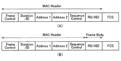
図5(A)は、MACフレームの基本的なフォーマット例を示す。本実施形態に係るデータフレーム、管理フレームおよび制御フレームは、このようなフレームフォーマットをベースとする。本フレームフォーマットは、MACヘッダ(MAC header)、フレームボディ(Frame body)及びFCSの各フィールドを含む。MACヘッダは、図5(B)に示すように、Frame Control、Duration/ID、Address1、Address2、Address3, Sequence Control、QoS Control及び HT(High Throughput) controlの各フィールドを含む。 FIG. 5A shows a basic format example of a MAC frame. The data frame, the management frame, and the control frame according to this embodiment are based on such a frame format. This frame format includes each field of a MAC header (MAC header), a frame body (Frame body), and an FCS. As shown in Fig. 5B, the MAC header includes fields of Frame Control, Duration/ID, Address1, Address2, Address3, Sequence Control, QoS Control, and HT (High Throughput) control.
これらのフィールドは必ずしもすべて存在する必要はなく、一部のフィールドが存在しない場合もあり得る。例えばAddress3フィールドが存在しない場合もある。また、QoS ControlおよびHT Controlフィールドの両方または一方が存在しない場合もある。またフレームボディフィールドが存在しない場合もあり得る。また図5には示されていない他のフィールドが存在してもよい。例えば、Address4フィールドがさらに存在してもよい。また後述するRU/AIDフィールドが、MACヘッダまたはフレームボディフィールドに存在してもよい。 Not all of these fields need to be present, and some fields may not be present. For example, the Address3 field may not exist. Also, both or one of the QoS Control and HT Control fields may not be present. It is also possible that the frame body field does not exist. There may be other fields not shown in FIG. For example, the Address4 field may be further present. The RU/AID field described later may be present in the MAC header or the frame body field.
Address1のフィールドには、受信先アドレス(Receiver Address;RA)が、Address2のフィールドには送信元アドレス(Transmitter Address;TA)が入り、Address 3のフィールドにはフレームの用途に応じてBSSの識別子であるBSSID(Basic Service Set IDentifier)(全てのビットに1を入れて全てのBSSIDを対象とするwildcard BSSID場合もある)か、あるいはTAが入る。ただし、後述するように、本実施形態では、Address1およびAddress2フィールドをここで述べたのとは別の方法で使用することを特徴の1つとしている。
A receiver address (Receiver Address; RA) is entered in the
Frame Controlフィールドには、前述したようにタイプ(Type)、サブタイプ(Subtype)という2つのフィールド等を設定する。データフレームか、管理フレームか、制御フレームかの大別はTypeフィールドで行われ、大別されたフレームの中での細かい種別、例えば制御フレームの中のBAフレームかBARフレーム、また管理フレームの中のBeaconフレームといった識別はSubtypeフィールドで行われる。後述するトリガーフレームも、タイプおよびサブタイプの組み合わせで区別してもよい。トリガーフレームは制御フレームの一種であることが有望である。 In the Frame Control field, two fields such as a type (Type) and a subtype (Subtype) are set as described above. A data field, a management frame, or a control frame is roughly classified according to the Type field, and a detailed type in the classified frame, for example, a BA frame or a BAR frame in a control frame, or a management frame The Beacon frame is identified by the Subtype field. The trigger frames described below may also be distinguished by a combination of type and subtype. The trigger frame is a promising type of control frame.
Duration/IDフィールドは媒体予約時間を記載し、他の端末宛てのMACフレームを受信した場合に、当該MACフレームを含む物理パケットの終わりから媒体予約時間に亘って、媒体が仮想的にビジーであると判定する。このような仮想的に媒体をビジーであると判定する仕組み、或いは、仮想的に媒体をビジーであるとする期間は、前述したように、NAV(Network Allocation Vector)と呼ばれる。QoSフィールドは、フレームの優先度を考慮して送信を行うQoS制御を行うために用いられる。 The Duration/ID field describes the medium reservation time, and when a MAC frame addressed to another terminal is received, the medium is virtually busy from the end of the physical packet including the MAC frame to the medium reservation time. To determine. Such a mechanism for determining that the medium is virtually busy, or a period during which the medium is virtually busy is called NAV (Network Allocation Vector), as described above. The QoS field is used to perform QoS control in which transmission is performed in consideration of frame priority.
管理フレームでは、固有のElement ID(IDentifier)が割り当てられた情報エレメント(Information element;IE)をFrame Bodyフィールドに設定する。フレームボディフィールドには、1つまたは複数の情報エレメントを設定できる。情報エレメントは、図6に示すように、Element IDフィールド、Lengthフィールド、情報(Information)フィールドの各フィールドを有する。情報エレメントは、Element IDで識別される。情報フィールドは、通知する情報の内容を格納し、Lengthフィールドは、情報フィールドの長さ情報を格納する。 In the management frame, an information element (Information element; IE) to which a unique Element ID (IDentifier) is assigned is set in the Frame Body field. One or more information elements can be set in the frame body field. As shown in FIG. 6, the information element has each field of an Element ID field, a Length field, and an information (Information) field. The information element is identified by the Element ID. The information field stores the content of information to be notified, and the Length field stores the length information of the information field.
FCSフィールドには、受信側でフレームの誤り検出のため用いられるチェックサム符号としてFCS(Frame Check Sequence)情報が設定される。FCS情報の例としては、CRC(Cyclic Redundancy Code)などがある。 In the FCS field, FCS (Frame Check Sequence) information is set as a checksum code used for the frame error detection on the receiving side. Examples of FCS information include CRC (Cyclic Redundancy Code).
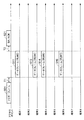
図7に、本実施形態に係る基地局(AP)101と、端末(STA)1〜端末(STA)8を含む複数の端末との動作シーケンス例を示す。端末1〜8はUL−OFDMA対応端末である。
FIG. 7 shows an operation sequence example of the base station (AP) 101 according to the present embodiment and a plurality of terminals including the terminal (STA) 1 to the terminal (STA) 8. The
本動作シーケンス例では、前提として、基地局と端末1〜8の一部または全部との間でCSMA/CAベースで個別に通信(シングルユーザ通信)が行われている。シングルユーザ通信では、例えば基本チャネル幅(例えば20MHz)の1チャネルで基地局および端末間で通信が行われている。シングルユーザ通信の例として、端末でアップリンク送信用のデータが保持されている場合、CSMA/CAに従って、無線媒体へのアクセス権を獲得する。このため、端末はDIFS/AIFS[AC]と、ランダムに決定したバックオフ時間とのキャリアセンス時間(待機時間)の間、キャリアセンスを行い、媒体(CCA)がアイドルと判断されると、例えば1フレームを送信するアクセス権を獲得する。端末は、送信するデータを含むデータフレーム(より詳細にはデータフレームを含む物理パケット)を送信し、基地局がこのデータフレームを正常に受信すると、データフレームの受信完了からSIFS時間後に、送達確認応答フレームであるACKフレーム(より詳細にはACKフレームを含む物理パケット)を返す。端末はACKフレームを受信することで、データフレームの送信が成功したと判断する。なお、基地局に送信するデータフレームはアグリゲーションフレーム(A-MPDU等)でもよく、基地局が応答する送達確認応答フレームはBAフレームでもよい(以下同様)。なお、DIFS/AIFS[AC]時間は、DIFSおよびAIFS[AC]のいずれか一方の時間を意味する。QoS対応でない場合はDIFS時間を指し、QoS対応の場合は、送信するデータのアクセスカテゴリ(AC:Access Category)(後述)に応じて決まるAIFS[AC]時間を指す。
In this operation sequence example, as a premise, communication (single user communication) is individually performed on the basis of CSMA/CA between the base station and some or all of the
基地局が、任意のタイミングでUL−OFDMAの開始を決定する。本例ではUL−OFDMA送信をシングルユーザ通信と同じチャネル(基本チャネル幅20MHzの1チャネル)で行う場合を想定する。つまり、基本チャネル幅20MHzのチャネル内に定義された複数のリソースユニットを用いてUL−OFDMA送信を行う場合を想定する。ただし、40MHz、80MHzなど、他のチャネル幅でUL−OFDMA送信を行うことも可能である。 The base station determines the start of UL-OFDMA at any timing. In this example, it is assumed that UL-OFDMA transmission is performed on the same channel as single-user communication (one channel having a basic channel width of 20 MHz). That is, it is assumed that UL-OFDMA transmission is performed using a plurality of resource units defined in a channel having a basic channel width of 20 MHz. However, it is also possible to perform UL-OFDMA transmission with other channel widths such as 40 MHz and 80 MHz.
基地局が、UL−OFDMA送信の開始を決定すると、UL−OFDMA送信のトリガーフレーム(より詳細にはトリガーフレームを含む物理パケット)501を送信する。トリガーフレーム501は、シングルユーザ通信と同じチャネルの基本チャネル幅のチャネルで送信する。トリガーフレームを含む物理パケットは、一例として、トリガーフレームの先頭に物理ヘッダを付加したものである。物理ヘッダは、一例として、図8に示すように、IEEE802.11規格で定義されているL−STF(Legacy−Short Training Field)、L−LTF(Legacy−Long TrainingField)、L−SIG(Legacy Signal Field)、を含む。L−STF、L−LTF、L−SIGは、例えば、IEEE802.11aなどのレガシー規格の端末が認識可能なフィールドであり、それぞれ信号検出、周波数補正(伝搬路推定)、伝送速度(伝送レート)などの情報が格納される。ここで述べた以外のフィールド(例えばレガシー規格の端末が認識できず、UL−OFDMA対応端末が認識できるフィールド)が含まれてもよい。
When the base station decides to start UL-OFDMA transmission, it transmits a UL-OFDMA transmission trigger frame (more specifically, a physical packet including a trigger frame) 501. The
トリガーフレーム501は、UL−OFDMA対応端末の他、レガシー端末も受信および復号可能なフレームでよい。なお、基地局がトリガーフレームを送信するにあたり、事前にCSMA/CAに従ってアクセス権を獲得しているものとする。アクセス権の獲得は前述した端末の場合と同様である。トリガーフレーム501のフレームフォーマットおよびその使用方法(解釈ルール)は、本実施形態では複数存在し、そのいずれかによってトリガーフレーム501を受信した際の端末の動作も異なる。本シーケンスの説明では代表的な動作の一例を説明し、バリエーションとしての動作は後述する。ここではトリガーフレーム501には一例として、UL−OFDMA送信で使用可能な複数のリソースユニットを特定する情報と、UL−OFDMA送信の候補となる複数の端末を特定する情報が含まれているとする。上記リソースユニットを特定する情報は、例えばチャネル内に定義された複数のリソースユニットの全部または一部を特定する。上記候補となる複数の端末を特定する情報は、例えば少なくとも1つのグループID、または複数の端末の各々の識別子(AIDまたはMACアドレスなど)を含む。ここで述べた以外の例も可能である。
The
基地局から送信されたトリガーフレーム501は端末1〜8で受信される。端末1〜8は、トリガーフレーム501を復号し、自端末がトリガーフレーム501で指定されたグループIDのグループに属しているかを判断する。なお、端末は、アソシエーションプロセス時またはその後の任意のタイミングで基地局から自端末が属するグループのグループIDの通知を受けている。自端末以外の端末とグループとの対応の通知も受けていてもよい。自端末がトリガーフレームで指定されたグループIDに属しており、かつ、アップリンク送信用のデータを保持している場合、トリガーフレーム501で指定された複数のリソースユニットから、自端末が使用するリソースユニットをランダムバックオフ手法に類似した方法に基づき選択する。アップリンク送信用のデータを保持していない端末は、選択する必要はないが、あえて選択する構成も可能である。選択する個数は事前に定められていていてもよいし、トリガーフレーム501で指定されてもよいし、その他の方法で把握してもよい。ここでは、上記のグループに属している各端末は、最大1つのリソースユニットが選択可能とする場合を想定する。
The
ここで、トリガーフレーム501ではリソースユニットを特定する情報として、n個のリソースユニット1〜nが指定されていたとする。リソースユニット1〜nは、UL−OFDMAで使用するチャネル内で定義された全リソースユニットでもよいし、一部のリソースユニットでもよい。リソースユニット1〜nは、例えば各々の識別子または番号であるRU#1〜RU#nによって識別されてもよい。複数のリソースユニットの集合を識別する識別子を別途定義し、当該集合の識別子を1つまたは複数、トリガーフレーム501で指定する構成も考えられる。この場合、端末は、当該集合の識別子から利用可能なリソースユニットを把握する。
Here, it is assumed that in the
本例では、端末1〜8のうち端末1、3、4、6が共通に属するグループが指定され、端末2、5、7、8の少なくとも1つが属するグループは指定されていなかったとする。一例として、端末1、3、4、6を含むグループと、端末2、5、7、8を含むグループが基地局で定義されており、前者のグループのグループIDのみが指定されていたとする。そして、端末1、3、4、6がそれぞれ、アップリンク用のデータを保持しており、これら全ての端末がリソースユニットの選択権を獲得し、リソースユニット1〜nからランダムに、リソースユニット2、4、6、7を選択したとする。端末1、3、4、6は、トリガーフレーム507の受信完了から一定時間T1後に、アップリンク送信用のデータを含むデータフレーム511、513、514、516(より詳細には当該データフレームを含む物理パケット)を、基地局に送信する。データフレーム511、513、514、516の送信は、端末1〜4がそれぞれ選択したリソースユニット2、4、6、7を用いて行う。
In this example, it is assumed that the group to which the
一定時間T1は、一例として、IEEE802.11無線LANのMACプロトコル仕様で規定されているフレーム間のタイムインターバルであるSIFS(Short Inter−frame Space)時間(=16μs)または、その他の事前に定義した時間(IFS)を用いることができる。一定時間T1は、システムまたは仕様で決められていてもよいし、ビーコンフレームあるいはその他の管理フレームなど、別の方法で事前に通知されてもよい。その他の例として、一定時間T1の値がトリガーフレーム501の所定フィールドに格納されており、端末1〜4は所定フィールドから一定時間T1の値を取得してもよい。
The fixed time T1 is, for example, a SIFS (Short Inter-frame Space) time (=16 μs), which is a time interval between frames defined in the MAC protocol specification of the IEEE 802.11 wireless LAN, or other predefined time. Time (IFS) can be used. The fixed time T1 may be determined by the system or the specifications, or may be notified in advance by another method such as a beacon frame or other management frame. As another example, the value of the fixed time T1 may be stored in a predetermined field of the
端末1、3、4、6が送信するデータフレームの送信タイミングは互いに同期され、これによりUL−OFDMA送信が実行されることになる。なお、端末が、アップリンク送信するデータがないにも拘わらずリソースユニットを選択する動作を行う場合、その端末は、予め定めた形式のフレーム、例えば物理ヘッダとMACヘッダは存在するもののデータフィールドが存在しないフレームであるNull Packet(ヌルパケット)を送信してもよい。あるいは、その端末は、リソースユニットの選択はしたものの、送信動作は何も行わないようにしてもよい。基地局では、ヌルパケットを受信した場合、当該端末は送信すべきデータが存在しなかったと判断してもよい。
The transmission timings of the data frames transmitted by the
基地局は、端末1、3、4、6からOFDMAで送信されるデータフレーム511、513、514、516(より詳細にはデータフレームを含む物理パケット)を受信する。基地局は、データフレーム511、513、514、516を、それぞれリソースユニット2、4、6、7で受信する。その他のリソースユニットでは、どの端末からもデータフレームの送信は行わないため、基地局でも、データフレームの受信は行わない。
The base station receives data frames 511, 513, 514, and 516 (more specifically, physical packets including data frames) transmitted by OFDMA from the
基地局は、端末1、3、4、6から送信されたデータフレームを正しく受信すると、各データフレームの受信から一定時間T2後に、送達確認応答フレーム521を端末1、3、4、6に送信する。一定時間T2は、一例として、IEEE802.11無線LANのMACプロトコル仕様で規定されているフレーム間のタイムインターバルであるSIFS(Short Inter−frame Space)時間(=16μs)または、その他の事前に定義した時間(IFS)を用いることができる。
When the base station correctly receives the data frames transmitted from the
送達確認応答フレーム513の送信として、BAフレームを端末1、3、4、6毎に、それぞれデータフレームが受信されたリソースユニットで送信する。基地局に送信されたデータフレームがA−MPDUでなく、通常(単一)のMPDUを含む場合は、BAフレームではなくACKフレームでもよい(なお、通常のMPDUの場合にBAフレームを返すことも可能である)。このように端末1、3、4、6毎にそれぞれのリソースユニットでBA(またはACK)フレームを送信することは、ダウンリンクのOFDMAで送達確認応答フレームを送信することに相当する。この場合、各端末はそれぞれのリソースユニットでBA(またはACK)フレームを受信する(そのようにリソースユニット単位で信号を受信できるように、受信フィルタを設定しておく)。別の方法として、BAフレーム(またはACKフレーム)を端末1、3、4、6に、ダウンリンクのMU−MIMOで送信することも可能である。ダウンリンクのMU−MIMOは、IEEE802.11acで規定されている。
As the transmission of the delivery
さらに別の方法として、端末1、3、4、6用の送達確認応答をすべて含む単一のフレームをチャネル幅帯域で送信(シングルユーザ送信)してもよい。この場合、このフレームのことを、Multi−STA BAフレームと呼んでもよい。具体的な構成としては、例えばIEEE802.11規格で定義されたMulti−TID BAフレームを流用してもよい。一例として、Multi−TID BAフレームのBA情報フィールドを端末数分配置し、各BA情報フィールドのTID情報サブフィールド内の予約フィールドに、端末の識別子(例えばAID(Association ID)またはAIDの一部)を設定する。各BA情報フィールドのBlock Ack Starting Sequence ControlサブフィールドおよびBlock Ack Bitmapサブフィールドには通常通り、送達確認応答を返すべきデータフレーム511、513、514、516に応じて値を設定すればよい。Multi−STA BAフレームのRA(受信先アドレス)は、端末1、3、4、6が共通に属するグループのマルチキャストアドレス、またはブロードキャストアドレスとすればよい。このようにすることで、1つのフレームで複数の端末にBAを通知できる。またFrame Controlフィールドのサブタイプとして、新たな値を定義してもよい。
As yet another method, a single frame including all acknowledgments for
端末1、3、4、6に、BAフレームではなくACKフレームを返す場合は、各BA情報フィールドのTID情報サブフィールド内の予約フィールドにおける一部のフィールドに端末の識別子を設定し、残りの一部のフィールドのビットを立てる(1にする)ようにする。そして、当該ビットを立てた場合に、Block Ack Starting Sequence ControlサブフィールドおよびBlock Ack Bitmapサブフィールドは省略する(存在しない)。これにより、1つのフレームで複数の端末のACKを通知できる。別の例としては、パーシャルステート動作を用い、対応するシーケンス番号をBlock Ack Bitmapサブフィールドで表現するようにする。ここで述べた例は、一例であり、Multi−TID BAフレーム以外の既存のフレームを流用してもよいし、既存のフレームを流用するのではなく、新規にフレームを定義してもよい。
When returning an ACK frame instead of a BA frame to the
上述した説明では送達確認応答フレーム521を端末1、3、4、6に一度に送信する例を示したが、端末1、3、4、6に順番に、BAフレームまたはACKフレームを返す方法も可能である。例えば、BAフレームを順番に返す際、任意の1台の端末(例えば端末1)には、データフレームの受信完了からSIFS時間後にBAフレームを返し、残りの端末については、BARフレームを端末から受信し、その応答としてBAフレームを送信することを行ってもよい。あるいは残りの端末については、基地局でBARフレームを受信せずにBAフレームを送信し、応答としてACKフレームを受信することを行ってもよい。ここで述べた以外の方法で、BAフレームまたはACKフレームを返すことも可能である。
In the above description, an example in which the delivery
基地局による送達確認応答フレーム521の送信後、基地局からのトリガーフレームの送信から再度同様のシーケンスが繰り返し行われてもよい。
After the transmission
上述した動作例では、トリガーフレームでグループIDにより指定された端末はリソースユニットの選択権があると、トリガーフレームで指定された複数のリソースユニットからランダムにリソースユニットを選択した。別の動作として、基地局はトリガーフレームで端末毎に個別にリソースユニットを指定し、トリガーフレームで指定された端末は、トリガーフレームで指定されたリソースユニットを選択する動作も可能である。例えばトリガーフレームで端末1、3、4、6の識別子(AID等)を指定するとともに、リソースユニット2、4、6、7の識別子をこれらの端末にそれぞれ個別に指定する。これにより図7と同様のシーケンスが行われる。リソースユニットをいくつか連続して同じ端末に割り当てるようにしてもよい。また、これらの動作(リソースユニットのランダム選択と個別指定)の両方を組み合わせた動作も可能である。また、基地局にまだ接続していない端末も、UL−OFDMAの対象としてトリガーフレームで指定することも可能である。以下、これらの動作を実現するための、トリガーフレーム501の構成例および使用例(解釈例)と、当該構成例に応じた基地局および端末の動作についてさらに詳細に説明する。
In the above-described operation example, when the terminal designated by the group ID in the trigger frame has the resource unit selection right, the resource unit is randomly selected from the plurality of resource units designated in the trigger frame. As another operation, the base station may individually specify the resource unit for each terminal in the trigger frame, and the terminal specified in the trigger frame may select the resource unit specified in the trigger frame. For example, the identifiers (AID, etc.) of the
図9(A)は、トリガーフレーム501の構成例を示す。図5に示したMACフレームのMACヘッダに、RU/AIDフィールドが追加され、Address3フィールド等、一部のフィールドは削除されている。ただし、これらの削除されたフィールドの一部または全部が図7のフレーム構成に存在してもかまわない。図9(B)は、RU/AIDフィールドがMACヘッダではなく、フレームボディフィールドに存在する場合の例である。フレームボディフィールドにRU/AIDフィールドを設ける場合、トリガーフレーム501が管理フレームであれば、図6に示したように情報エレメントとしてRU/AIDフィールドを設けることが考えられる。制御フレームまたはデータフレームであれば、RU/AIDフィールドを識別可能な形式で、フレームボディフィールドに追加すればよい。以下の説明では、特に区別する必要がある場合を除き、RU/AIDフィールドがMACヘッダにあるかフレームボディフィールドにあるかは問わないものとする。
FIG. 9A shows a configuration example of the
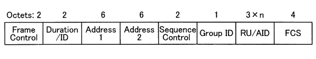
図10は、トリガーフレームのRU/AIDフィールドの構成例と、各フィールド長の例を示す。ここに示したフィールド長はあくまで一例であり、他の値が用いられてもかまわない。例えばここではオクテット(8ビット)単位でフィールド長を示しているが、オクテット単位でなくてもかまわない。「3×n」は、3にnを乗じた値を意味する。 FIG. 10 shows a configuration example of the RU/AID field of the trigger frame and an example of each field length. The field lengths shown here are merely examples, and other values may be used. For example, although the field length is shown here in units of octets (8 bits), it does not have to be in units of octets. “3×n” means a value obtained by multiplying 3 by n.
RU/AIDフィールドは、RUフィールド(RU_1〜RU_n)とAIDフィールド(AID_1〜AID_n)とのn個の対(組)を含む。本フレームフォーマットの基本的な使用方法として、RUフィールドとAIDフィールドを用いて、リソースユニットの指定と、当該リソースユニットを割り当てる端末の指定を行う。RUフィールドでリソースユニットの識別子を設定し、AIDフィールドで、当該リソースユニットを割り当てる端末の識別子(ここではAID)を設定する。これにより、リソースユニットごとに端末を指定し、各端末が、指定されたリソースユニットを使用する。ここで、フレームコントールフィールドのタイプは“制御”または“管理”とし、サブタイプはトリガーフレームに対応する新たな値を定義する。タイプは“制御”または“管理”ではなく、“データ”でもかまわない。この場合、サブタイプを新たな値に定義する代わりに、トリガーフレームか否かを通知するフィールドをMACヘッダに別途設け、そのフィールドにビットを立てることでトリガーフレームであることの通知を行ってもかまわない。Duration/IDフィールドには、トリガーフレームの末尾から無線媒体の使用を占有したい期間長を指定する。例えば送達確認応答フレームの末尾までの時間長を指定する。Sequence ControlおよびFCSフィールドは、通常通り値を設定すればよい。Address1フィールドには、RAとして、ブロードキャストアドレスまたはマルチキャストアドレスを設定すればよい。Address2フィールドにはTAとして、基地局のMACアドレス(BSSID)を設定すればよい。なお、n(RUフィールドとAIDフィールドの組の個数)は固定でもよいし、可変でもよい。可変の場合、RU/AIDフィールドの先頭にnを定めるフィールドを設けてもよいし、RU/AIDフィールドの終わりを通知するフィールドを設けてもよい。終わりを通知するフィールドは、リソースユニットの識別子とAIDの組み合わせにない特別な値でもよい。 The RU/AID field includes n pairs (sets) of the RU field (RU_1 to RU_n) and the AID field (AID_1 to AID_n). As a basic method of using this frame format, the resource unit and the terminal to which the resource unit is assigned are specified using the RU field and the AID field. The resource unit identifier is set in the RU field, and the terminal identifier (AID in this case) of the terminal to which the resource unit is assigned is set in the AID field. As a result, a terminal is designated for each resource unit, and each terminal uses the designated resource unit. Here, the type of the frame control field is "control" or "management", and the subtype defines a new value corresponding to the trigger frame. The type may be "data" instead of "control" or "management". In this case, instead of defining the subtype to a new value, a field for notifying whether the frame is a trigger frame is separately provided in the MAC header, and a bit is set in the field to notify that the frame is a trigger frame. I don't care. The Duration/ID field specifies the period length from the end of the trigger frame where the user wants to occupy the wireless medium. For example, the time length to the end of the delivery confirmation response frame is designated. Values may be set as usual in the Sequence Control and FCS fields. A broadcast address or a multicast address may be set as RA in the Address1 field. The MAC address (BSSID) of the base station may be set as TA in the Address2 field. Note that n (the number of pairs of RU field and AID field) may be fixed or variable. In the case of being variable, a field for determining n may be provided at the beginning of the RU/AID field, or a field for notifying the end of the RU/AID field may be provided. The end notification field may be a special value that is not included in the combination of the resource unit identifier and the AID.
以下では、このようなRU/AIDフィールドの構成を有するフレームフォーマットを利用して、図7で説明したような、端末群をグループIDで指定し、当該グループIDに属する端末群にランダムバックオフ手法に類似した方法に基づきリソースユニットを選択させて、フレーム送信を行わせる例を示す。 In the following, using a frame format having such a structure of the RU/AID field, a terminal group is designated by a group ID as described in FIG. 7, and a random backoff method is applied to a terminal group belonging to the group ID. An example is shown in which a resource unit is selected based on a method similar to, and frame transmission is performed.
(第1の例)
この場合も、RUフィールド(RU_1〜RU_n)には、利用可能なリソースユニットの識別子を設定する。図10の例では、n個のRUフィールドが存在し、これらのRUフィールドにそれぞれ該当するリソースユニットの識別子を設定する。一方、n個のAIDフィールド(AID_1〜AID_n)には、第1の例では、任意の値を設定する。
(First example)
Also in this case, the identifiers of available resource units are set in the RU fields (RU_1 to RU_n). In the example of FIG. 10, there are n RU fields, and the identifiers of the corresponding resource units are set in these RU fields. On the other hand, arbitrary values are set in the n AID fields (AID_1 to AID_n) in the first example.
一方、フレームコントールフィールドのタイプは“制御”または“管理”とし、サブタイプはトリガーフレームに対応する新たな値を定義する。タイプは“制御”または“管理”ではなく、“データ”でもかまわない。この場合、サブタイプを新たな値に定義する代わりに、トリガーフレームか否かを通知するフィールドをMACヘッダに別途設け、そのフィールドにビットを立てることでトリガーフレームであることの通知を行ってもかまわない。Duration/IDフィールドには、トリガーフレームの末尾から無線媒体の使用を占有したい期間長を指定する。例えば送達確認応答フレームの末尾までの時間長を指定する。Sequence ControlおよびFCSフィールドは、通常通り値を設定すればよい。 On the other hand, the type of the frame control field is “control” or “management”, and the subtype defines a new value corresponding to the trigger frame. The type may be "data" instead of "control" or "management". In this case, instead of defining the subtype to a new value, a field for notifying whether the frame is a trigger frame is separately provided in the MAC header, and a bit is set in the field to notify that the frame is a trigger frame. I don't care. The Duration/ID field specifies the period length from the end of the trigger frame where the user wants to occupy the wireless medium. For example, the time length to the end of the delivery confirmation response frame is designated. Values may be set as usual in the Sequence Control and FCS fields.
Address1フィールドには、候補端末(図7の例では端末1、3、4、6)が属しているグループのグループIDを設定する。通常、Address1フィールドにはRA(ユニキャストアドレス、ブロードキャストアドレスまたはマルチキャストアドレス)を設定するため、グループIDを設定するのは通常とは異なる動作である。このため、Address1フィールドにグループIDが設定されていることを通知する必要がある。そこで、Address2フィールドに、基地局のMACアドレス(BSSID)のIndividual/Groupビット(特定位置のビット)を1に変換したものを設定する。通常、Address2フィールドにはTAを設定するため、基地局のMACアドレス(BSSID)を設定するのが通常の動作である。ここでは、Address1フィールドにグループIDが設定されていることを通知するため、基地局のMACアドレス(BSSID)のIndividual/Groupビットを1に変換したものを設定する。Individual/Groupビットは、MACアドレスの8ビット目(MACアドレスを伝送するときは先頭からオクテット単位で送信し、各オクテットでは最下位ビットから順に送信するため、Individual/Groupビットは、MACアドレスを伝送するときの先頭ビットでもある)であり、端末(基地局を含む)のMACアドレスのIndividual/Groupビットは0である。なお、ブロードキャストアドレスまたはマルチキャストアドレスの場合は1である。そこで、このIndividual/Groupビットを、0から1に変換することで、端末にAddress1フィールドにグループIDが設定されていることを通知する(通常は、トリガーフレームの送信は基地局からであるため、Address2フィールドに設定するTAは基地局のMACアドレスであり、Individual/Groupビットは0であることを利用している)。よって、端末は、Address2フィールドのIndividual/Groupビットが1であるため、Address1フィールドにグループIDが設定されていると判断できるとともに、トリガーフレームの送信元アドレスが、Address2フィールドのビット列のIndividual/Groupビットを1から0に戻したものであると判断することもできる。したがって、端末がデータフレームを送信する際のRAとして、Address2フィールドのビット列のIndividual/Groupビットを1から0に戻したもの(すなわち基地局のMACアドレス)を用いることができる。
In the Address1 field, the group ID of the group to which the candidate terminal (
なお、n(RUフィールドとAIDフィールドの組の個数)は固定でもよいし、可変でもよい。可変の場合、RU/AIDフィールドの先頭にnを定めるフィールドを設けてもよいし、RU/AIDフィールドの終わりを通知するフィールドを設けてもよい。終わりを通知するフィールドは、リソースユニットの識別子とAIDの組み合わせにない特別な値でもよい。 Note that n (the number of pairs of RU field and AID field) may be fixed or variable. In the case of being variable, a field for determining n may be provided at the beginning of the RU/AID field, or a field for notifying the end of the RU/AID field may be provided. The end notification field may be a special value that is not included in the combination of the resource unit identifier and the AID.
上述したように設定されたトリガーフレームを受信した端末は、例えばフレームコントロールフィールドのタイプおよびサブタイプの値から、トリガーフレームを受信したことを把握する。Address2フィールドのIndividual/Groupが1であることから、Address1フィールドにグループIDが設定されていることを把握し、Address1フィールドに設定されているグループIDを読み出す。当該グループIDが示すグループに自端末が属しているかを判断し、属していない場合は、トリガーフレームを廃棄して処理を終了する。当該グループIDが示すグループに自端末が属している場合は、RU/AIDフィールドを確認し、n個のRUフィールドに設定された識別子により示されるリソースユニットを、利用候補となるリソースユニットとして把握する。n個のAIDフィールドは無視する。端末は、例えば予めランダムに選択したバックオフカウンタ値から利用候補となるリソースユニットの数を引き、0以下になるとリソースユニットの選択権があるとして、利用候補となるリソースユニットの中からランダムに自端末が使用するリソースユニットを選択する。ここでは1つのリソースユニットを選択することを想定するが、前述したように複数のリソースユニットを選択してもよい。ランダムに選択する方法は何でもかまわない。例えば一定の桁数の数字を発生させる乱数器を用いて、乱数値をnで除算したときの余りの値に1を加算した番号のリソースユニットを特定してもよい。この場合、余りの値がゼロであればリソースユニット1、余りの値がn−1であれば、リソースユニットnを選択する。ここで述べた例は一例に過ぎず、別の方法を用いても、もちろんかまわない。端末は、ランダムに選択したリソースユニットを用いて、上述したようにデータフレームを送信する。なお、データフレームのRA(Address1フィールドの値)は基地局のMACアドレス(BSSID)、TA(Address2フィールドの値)は自端末のMACアドレスである。
The terminal that has received the trigger frame set as described above recognizes that the trigger frame has been received, for example, from the values of the type and subtype of the frame control field. Since Individual/Group in the Address2 field is 1, it is grasped that the group ID is set in the Address1 field, and the group ID set in the Address1 field is read out. It is determined whether or not the terminal itself belongs to the group indicated by the group ID. If the terminal does not belong to the group, the trigger frame is discarded and the process ends. When the terminal itself belongs to the group indicated by the group ID, the RU/AID field is confirmed, and the resource unit indicated by the identifiers set in the n RU fields is grasped as the resource unit to be used. . Ignore the n AID fields. For example, the terminal subtracts the number of resource units that are usage candidates from the back-off counter value that is randomly selected in advance, and determines that it has the right to select a resource unit when it becomes 0 or less, and randomly selects from among the resource units that are usage candidates. Select the resource unit used by the terminal. Although it is assumed here that one resource unit is selected, a plurality of resource units may be selected as described above. It doesn't matter what method you choose at random. For example, a random number generator that generates a certain number of digits may be used to specify a resource unit having a number obtained by adding 1 to the remainder value when the random number value is divided by n. In this case, the
上述した第1の例によれば、グループIDで指定されたグループに属する端末のみがUL−OFDMAの候補端末となるため、トリガーフレームを受信した全端末が候補端末となる場合よりも、ランダムに選択するリソースユニットが端末間で重複する可能性を低減できる。なお、複数の端末間で同じリソースユニットが選択された場合、基地局で当該リソースユニットで信号干渉が生じ、これら複数の端末からのフレームを正常に受信できなくなる。 According to the first example described above, only the terminals belonging to the group specified by the group ID are candidate terminals for UL-OFDMA, so that the terminals are randomly selected as compared to the case where all terminals that have received the trigger frame are candidate terminals. It is possible to reduce the possibility that resource units to be selected overlap between terminals. In addition, when the same resource unit is selected among a plurality of terminals, signal interference occurs in the resource unit in the base station, and frames from these plurality of terminals cannot be normally received.
(第2の例)
第2の例は、n個のAIDフィールドの設定と、端末の動作が第1の例と異なる。以下第1の例との差分を説明する。n個のAIDフィールドには、AIDとして未使用の値、もしくは端末に割り当てたAIDを設定する。“AIDとして未使用の値”とは、基地局が割り当て可能なAIDの値の範囲外の値のことである。例えば基地局が2オクテット(16ビット)のうちの14個のビットを使ってAIDを表現する場合、基地局が割り当て可能なAIDの値の範囲が1以上2007以下であれば、AIDフィールドの2オクテット(16ビット)のうち14個のビット(第0〜第13ビット)をすべて0もしくは、2008〜16383内の値に設定する。第14ビットおよび第15ビットは固定値(例えば“11”)を設定する。なお、ここで述べたAIDの未使用の値の設定例は、IEEE802.11規格で定められたDuration/IDフィールドの予約領域を利用する方法に類似している(IEEE Std 802.11(TM)−2012のテーブル8−3参照)。端末にランダムにリソースユニットの選択を行わせる場合は、該当するAIDフィールドに、AIDとして未使用の値を設定する。一方、端末が使用するリソースユニットを指定する場合は、該当するAIDフィールドに当該端末に割り当てたAIDを設定する。n個のAIDフィールドにすべて、AIDとして未使用の値を設定する場合、n個のこれらのフィールドに設定する値はすべて共通の値でもよいし、そうでなくてもよい。
(Second example)
The second example is different from the first example in the setting of n AID fields and the operation of the terminal. The difference from the first example will be described below. In the n AID fields, unused values or AIDs assigned to terminals are set. The “unused value as AID” is a value outside the range of AID values that can be assigned by the base station. For example, when the base station uses 14 bits of 2 octets (16 bits) to represent the AID, if the range of the AID value that can be assigned by the base station is 1 or more and 2007 or less, 2 of the AID field is set. All 14 bits (0th to 13th bits) of the octet (16 bits) are set to 0 or a value within 2008 to 16383. Fixed values (for example, "11") are set in the 14th and 15th bits. Note that the setting example of the unused value of the AID described here is similar to the method of using the reserved area of the Duration/ID field defined in the IEEE 802.11 standard (IEEE Std 802.11(TM)). -See Table 8-3 of 2012). When the terminal is made to randomly select the resource unit, an unused value is set as the AID in the corresponding AID field. On the other hand, when designating the resource unit used by the terminal, the AID assigned to the terminal is set in the corresponding AID field. When setting unused values as AIDs in all the n AID fields, the values set in these n fields may or may not be common values.
端末は、AIDフィールドの値が、“AIDとして未使用の値”であるかを判断し、“AIDとして未使用の値” (上述の例であれば第0〜第13ビットが0もしくは2008以上の値を表すビットで、第14および第15ビットが“11”の場合)であれば、当該リソースユニットが利用可能であると判断する。AIDとして使用され得る値であれば(上述の例であれば第0〜第13ビットが1〜2007内の値を表すビットで、第14および第15ビットが“11”の場合)は、当該リソースユニットは、当該AIDが自端末のAIDかを判断する。自端末のAIDであれば、自端末が当該リソースユニットの使用を基地局によって指定されているものと判断する。自端末のAIDでなければ、当該リソースユニットは自端末で利用できないと判断する。端末は、自端末に指定されたリソースユニットがあれば、そのリソースユニットを選択する。通信に必要なリソースユニット数が複数(H個)の場合に、指定されたリソースユニット数がそのHに満たない場合は、その差分のリソースユニットだけ、利用可能なリソースユニットからランダムに選択すればよい。 The terminal judges whether the value of the AID field is “unused value as AID” and “unused value as AID” (in the above example, the 0th to 13th bits are 0 or 2008 or more). If the 14th and 15th bits are “11”), it is determined that the resource unit is available. If the value can be used as the AID (in the above example, the 0th to 13th bits are bits representing the value within 1 to 2007, and the 14th and 15th bits are “11”), The resource unit determines whether the AID is the AID of its own terminal. If it is the AID of the own terminal, the own terminal determines that the use of the resource unit is designated by the base station. If it is not the AID of the own terminal, it is determined that the resource unit cannot be used by the own terminal. If there is a resource unit designated for the terminal, the terminal selects that resource unit. When the number of resource units required for communication is plural (H) and the specified number of resource units is less than H, only the resource units of the difference should be randomly selected from the available resource units. Good.
上述した第2の例によれば、UL−OFDMAの候補端末を特定のグループに限定できるとともに、端末ごとに使用させるリソースユニットを指定することも可能となる。これにより例えば端末が複数のリソースユニットを使用する場合に、一部のリソースユニットは基地局が指定し、残りのリソースユニットはランダムに選択することも可能になる。基地局が指定したリソースユニットについては他の端末が使用することがないため、基地局での当該リソースユニットでの端末間の干渉は発生せず、より確実な通信が期待できる。 According to the above-described second example, it is possible to limit UL-OFDMA candidate terminals to a specific group and also to specify a resource unit to be used for each terminal. By this means, for example, when the terminal uses a plurality of resource units, some base stations can be designated by the base station and the remaining resource units can be randomly selected. Since the resource unit designated by the base station is not used by other terminals, interference between terminals at the resource unit at the base station does not occur and more reliable communication can be expected.
(第3の例)
第2の例では、AIDフィールドに、AIDとして未使用の値、もしくは端末に割り当てたAIDを設定したが、本例では、AIDとして未割り当ての値、もしくは端末に割り当てたAIDを設定する。第2の例との差分を説明する。AIDとして未割り当ての値は、AIDとして未使用の値に加えて、基地局がAIDとして割り当て可能な範囲のAIDの値であるが、まだ割り当てていないAIDを含む。基地局が、各端末に端末とAIDの一覧を通知する場合には、この方法でも、第2の例と同様の動作が可能になる。すなわち、基地局は、端末にランダムにリソースユニットの選択を行わせる場合は、該当するAIDフィールドに、AIDとして未割り当ての値を設定する。一方、端末が使用するリソースユニットを指定する場合は、該当するAIDフィールドに当該端末に割り当てたAIDを設定する。端末は、AIDフィールドの値が、“AIDとして未割り当ての値”であるかを上記の一覧を利用して判断し、“AIDとして未割り当ての値”であれば、当該するリソースユニットが利用可能であると判断する。AIDとして割当済みの値であれば、当該値が自端末のAIDかを判断し、自端末のAIDであれば、自端末が当該するリソースユニットの使用を基地局によって指定されているものと判断する。自端末のAIDでなければ、当該リソースユニットは自端末で利用できないと判断する。端末は、自端末に指定されたリソースユニットがあれば、そのリソースユニットを選択する。通信に必要なリソースユニット数が複数(H個)の場合に、指定されたリソースユニット数がそのHに満たない場合は、その差分のリソースユニットだけ、利用可能なリソースユニットからランダムに選択すればよい。
(Third example)
In the second example, the unused value or the AID assigned to the terminal is set in the AID field, but in this example, the unassigned value or the AID assigned to the terminal is set as the AID. The difference from the second example will be described. The unallocated value as the AID is a value of the AID within a range that the base station can allocate as the AID, in addition to the unused value as the AID, but includes an AID that has not been allocated yet. When the base station notifies each terminal of the list of terminals and AIDs, this method also enables the same operation as in the second example. That is, when the base station randomly selects a resource unit, the base station sets an unallocated value as the AID in the corresponding AID field. On the other hand, when designating the resource unit used by the terminal, the AID assigned to the terminal is set in the corresponding AID field. The terminal determines whether or not the value of the AID field is “unassigned value as AID” by using the above list, and if “unassigned value as AID”, the relevant resource unit can be used It is determined that If it is a value that has been assigned as an AID, it is determined whether the value is the AID of the own terminal, and if it is the AID of the own terminal, it is determined that the use of the relevant resource unit by the own terminal is designated by the base station. To do. If it is not the AID of the own terminal, it is determined that the resource unit cannot be used by the own terminal. If there is a resource unit designated for the terminal, the terminal selects that resource unit. When the number of resource units required for communication is plural (H) and the number of designated resource units is less than H, only the resource units of the difference should be randomly selected from the available resource units. Good.
上述した第3の例によれば、第2の例と同様の効果を得ることができる。 According to the third example described above, the same effect as that of the second example can be obtained.
(第4の例)
第4の例では、基地局は、AIDフィールドに、グループIDのグループに属している端末のうち、該当リソースブロックの使用を禁止する端末のAID、もしくは、AIDとして未使用の値を設定する。第1〜第3の例との差分を説明する。特定の端末の使用は禁止したいが、残りの端末のいずれも使用を許可する場合には、AIDフィールドに使用を禁止する端末のAIDを設定する。グループIDのグループに属しているすべての端末のいずれの使用も許可する場合には、AIDとして未使用の値を設定する。AIDとして未使用の値の代わりに、第3の例と同様に、AIDとして未割り当ての値を用いてもよい。端末は、AIDフィールドに自端末のAIDが設定されているリソースユニットについては、自端末はそのリソースユニットは使用できないと判断する。AIDとして未使用の値(もしくはAIDとして未割り当ての値)が設定されているリソースユニットは利用可能であると判断する。端末は、利用可能なリソースユニットの中からランダムに、自端末が使用するリソースユニットを選択する。
(Fourth example)
In the fourth example, the base station sets, in the AID field, the AID of a terminal that prohibits the use of the resource block of the terminals belonging to the group having the group ID, or an unused value as the AID. Differences from the first to third examples will be described. When it is desired to prohibit the use of a specific terminal but to permit the use of any of the remaining terminals, the AID of the prohibited terminal is set in the AID field. When permitting use of all terminals belonging to the group of the group ID, an unused value is set as the AID. As with the third example, an unassigned value may be used as the AID instead of the unused value as the AID. The terminal determines that the resource unit whose own AID is set in the AID field cannot be used by the terminal itself. It is determined that the resource unit in which an unused value (or an unassigned value as the AID) is set as the AID is available. The terminal randomly selects a resource unit used by the terminal itself from the available resource units.
上述した第4の例によれば、あるリソースユニットについて、特定の端末には使用を禁止しつつ、他の端末に対してランダムに当該リソースユニットを選択することを許容できる。 According to the fourth example described above, it is possible to prohibit the use of a certain resource unit by a specific terminal, but allow other terminals to randomly select the resource unit.
(第5の例)
第5の例では、トリガーフレームのAddress1フィールドにグループIDが設定されていることを通知する方法が、第1〜第4の例と異なる。
(Fifth example)
The fifth example is different from the first to fourth examples in the method of notifying that the group ID is set in the Address1 field of the trigger frame.
なお、Address1フィールドにグループIDが設定されていることを通知する必要がある理由は、通常は、Address1フィールドにはユニキャストアドレス、ブロードキャストアドレス、またはマルチキャストアドレスを設定し、グループIDが設定されることは想定されていない。したがって、Address1フィールドにグループIDが設定されているのか、ブロードキャストまたはマルチキャストなどのアドレスが設定されているかを区別できるようにする必要がある。 The reason why it is necessary to notify that the group ID is set in the Address1 field is that a unicast address, a broadcast address, or a multicast address is usually set in the Address1 field and the group ID is set. Is not supposed. Therefore, it is necessary to be able to distinguish whether a group ID is set in the Address1 field or an address such as broadcast or multicast is set.
第1〜第4の例ではグループIDが設定されていることを通知するために、Address2フィールドのIndividual/Groupビットを1に変換したが、本例ではIndividual/Groupビットは0を維持する。すなわち、Address2フィールドには、通常通り、基地局のMACアドレス(BSSID)を設定する。その代わりに、グループIDが設定されていることは、別のフィールドを用いて端末に通知する。例えば、フレームコントロールフィールドの予約領域を用いて、グループIDの有無を設定する。または、図5に示したQoSフィールドをトリガーフレームにも残し、当該QoSフィールド内の予約領域にグループIDの有無を設定する。または、MACヘッダに、新規のフィールド、例えば図11に示すHE(High Efficiency)コントロールフィールドを設け、当該HEコントロールフィールドに、グループIDの有無を設定する。グループIDの有無を通知すること以外は、第1〜第4の例と同様である。 In the first to fourth examples, the Individual/Group bit of the Address2 field is converted to 1 in order to notify that the group ID is set, but in this example, the Individual/Group bit maintains 0. That is, the MAC address (BSSID) of the base station is set in the Address2 field as usual. Instead, the fact that the group ID has been set is notified to the terminal using another field. For example, the presence or absence of the group ID is set using the reserved area of the frame control field. Alternatively, the QoS field shown in FIG. 5 is also left in the trigger frame, and the presence or absence of the group ID is set in the reserved area in the QoS field. Alternatively, a new field such as a HE (High Efficiency) control field shown in FIG. 11 is provided in the MAC header, and the presence or absence of a group ID is set in the HE control field. The procedure is the same as in the first to fourth examples except that the presence/absence of the group ID is notified.
(第6の例)
第6の例では、トリガーフレームのAddress1フィールドに、グループIDが設定されていることを通知する方法が、第1〜第5の例と異なる。以下、第5の例との差分を中心に説明する。第5の例では、グループIDが設定されていることを通知するために、新たなフィールドを設けるか、既存のフィールドの予約領域を用いた。これに対して、第6の例では、RU/AIDフィールドのAIDフィールドを利用する。AIDフィールドに、上述した“AIDとして未使用の値”をAIDフィールドに設定する。すべてのAIDフィールドに入れてもよいし、特定の1つまたは複数のAIDフィールド、例えば先頭のAIDフィールドにのみ入れてもよい。第6の例では、AIDフィールドに“AIDとして未使用の値”が設定されていることは、Address1フィールドにグループIDが設定されていることを意味する。“AIDとして未使用の値”の代わりに、“AIDとして未割り当ての値”を用いてもかまわない。
(Sixth example)
The sixth example differs from the first to fifth examples in the method of notifying that the group ID is set in the Address1 field of the trigger frame. Hereinafter, the difference from the fifth example will be mainly described. In the fifth example, in order to notify that the group ID is set, a new field is provided or the reserved area of the existing field is used. On the other hand, in the sixth example, the AID field of the RU/AID field is used. In the AID field, the above-mentioned "unused value as AID" is set in the AID field. It may be included in all AID fields, or may be included in only one or more specific AID fields, for example, the first AID field. In the sixth example, setting an "unused value as the AID" in the AID field means that the group ID is set in the Address1 field. Instead of "unused value as AID", "unassigned value as AID" may be used.
端末はトリガーフレームを受信すると(受信したフレームが、フレームコントロールフィールドのタイプおよびサブタイプにより、トリガーフレームであることを認識すると)、RU/AIDフィールド内のいずれかのAIDフィールド、または特定の1つまたは複数のAIDフィールドの値を確認し、“AIDとして未使用の値”(あるいは“AIDとして未割り当ての値”)であれば、Address1フィールドにグループIDが設定されていることを把握する。あるいは、RU/AIDフィールド内の全てのAIDフィールドの値を確認して、すべてが“AIDとして未使用の値”(あるいは“AIDとして未割り当ての値”)であれば、Address1フィールドにグループIDが設定されていることを把握してもよい。端末はAddress1フィールドにグループIDが設定されていることを把握すると、Address1フィールドに設定された値を読み出して、当該値が示すグループIDのグループに自端末が属しているかを判断する。当該グループに自端末が属している場合は、RU/AIDフィールド内の各RUフィールドに設定された値が示すリソースユニットを、自端末が利用可能なリソースユニットとして特定する。前述のように特定したリソースユニットの中からランダムに、自端末が使用するリソースユニットを選択する。以降の動作は第1の例と同様である。 When the terminal receives a trigger frame (it recognizes that the received frame is a trigger frame depending on the type and subtype of the frame control field), it can use any AID field in the RU/AID field, or a specific one. Alternatively, the values of a plurality of AID fields are confirmed, and if the value is “unused value as AID” (or “unallocated value as AID”), it is grasped that the group ID is set in the Address1 field. Alternatively, check the values of all the AID fields in the RU/AID field, and if all are "unused values as AIDs" (or "unassigned values as AIDs"), the group ID is set in the Address1 field. You may know that it is set. When the terminal recognizes that the group ID is set in the Address1 field, it reads the value set in the Address1 field and determines whether the terminal belongs to the group having the group ID indicated by the value. When the own terminal belongs to the group, the resource unit indicated by the value set in each RU field in the RU/AID field is specified as the resource unit that can be used by the own terminal. The resource unit used by the own terminal is randomly selected from the resource units specified as described above. The subsequent operation is the same as in the first example.
(第7の例)
第7の例では、トリガーフレームのフォーマットとして図12に示すものを用いる。図9に示したフォーマット例と異なる点は、RU/AIDフィールドがAID通知フィールド(AID Notification Field)に置換されたことである。AID通知フィールドには、n個のAIDフィールド(AID_1、AID_2、・・・AID_n)が含まれる。各AIDフィールドはそれぞれ予め定められたリソースユニットに対応づけられている。例えばAID_1はリソースユニット1、AID_2はリソースユニット2に対応づけられているなどである。どのAIDフィールドがどのリソースユニットに対応づけられているかは、事前に基地局から各端末に通知してもよいし、システムまたは仕様で予め定められていても良い。各AIDフィールドおよびその他のフィールドの設定方法はこれまで述べた例と同様である。また、トリガーフレームを受信した場合の端末も動作も、RUフィールドを確認する動作が不要な点以外は、これまでの例と同様である。
(Seventh example)
In the seventh example, the format shown in FIG. 12 is used as the format of the trigger frame. The difference from the format example shown in FIG. 9 is that the RU/AID field has been replaced with an AID notification field (AID Notification Field). The AID notification field includes n AID fields (AID_1, AID_2,... AID_n). Each AID field is associated with a predetermined resource unit. For example, AID_1 is associated with
(第8の例)
第8の例では、トリガーフレームのフォーマットとして図13に示すものを用いる。図9に示したフォーマット例と異なる点は、RU/AIDフィールドがRU通知フィールド(RU Notification Field)に置換されたことである。RU通知フィールドには、n個のRUフィールドが含まれる。各RUフィールドには、第1〜第6の例と同様に、UL−OFDMAで利用可能なリソースユニットの識別子を設定する。その他のフィールドの設定方法は、第1の例または第5の例と同様である。
(Eighth example)
In the eighth example, the format of the trigger frame shown in FIG. 13 is used. The difference from the format example shown in FIG. 9 is that the RU/AID field is replaced with an RU notification field. The RU notification field includes n RU fields. Similar to the first to sixth examples, an identifier of a resource unit that can be used in UL-OFDMA is set in each RU field. The setting method of the other fields is the same as in the first example or the fifth example.
例えば、第1の例に準じて設定するならば、Address1フィールドにはグループIDを設定し、Address2フィールドには基地局のMACアドレスのIndividual/Groupビットを0から1に置換したものを設定する。またフレームコントロールフィールドのタイプは“制御”または“管理”とし、サブタイプはトリガーフレーム用に新たに定義した値を用いるなどとする。あるいは、タイプを“データ”としてもよい。この場合、サブタイプを新たな値に定義する代わりに、トリガーフレームか否かを通知するフィールドをMACヘッダに別途設け、そのフィールドにビットを立てることでトリガーフレームであることの通知を行ってもかまわない。 For example, if setting is performed according to the first example, a group ID is set in the Address1 field, and an Individual/Group bit of the MAC address of the base station is replaced with 0 to 1 in the Address2 field. The type of the frame control field is “control” or “management”, and the subtype uses a newly defined value for the trigger frame. Alternatively, the type may be "data". In this case, instead of defining the subtype to a new value, a field for notifying whether the frame is a trigger frame is separately provided in the MAC header, and a bit is set in the field to notify that the frame is a trigger frame. I don't care.
また、第5の例に準じて設定する場合、Address1フィールドにはグループIDを設定し、Address2には基地局のMACアドレス(BSSID)を設定する。また、フレームコントロールフィールドの予約領域またはQoSフィールド(図5参照)内の予約領域等にグループIDの有無を設定する。または、MACヘッダに、例えば図11に示すHE(High Efficiency)コントロールフィールドを設け、当該HEコントロールフィールドに、グループIDの有無を設定する。フレームコントロールフィールドの設定は、上記第1の例等と同様である。 Further, when setting according to the fifth example, a group ID is set in the Address1 field and a MAC address (BSSID) of the base station is set in Address2. Further, the presence or absence of a group ID is set in the reserved area of the frame control field or the reserved area in the QoS field (see FIG. 5). Alternatively, for example, a HE (High Efficiency) control field shown in FIG. 11 is provided in the MAC header, and the presence or absence of a group ID is set in the HE control field. The setting of the frame control field is the same as in the first example and the like.
端末はトリガーフレームを受信すると(例えば受信したフレームが、フレームコントロールフィールドのタイプおよびサブタイプにより、トリガーフレームであることを認識すると)、RU通知フィールド内の各RUフィールドから利用可能なリソースユニットを把握し、把握したリソースユニットの中からランダムにリソースユニットを選択する。以降の動作は第1の例等と同様である。 When the terminal receives the trigger frame (for example, when the terminal recognizes that the received frame is the trigger frame according to the type and subtype of the frame control field), it knows the available resource unit from each RU field in the RU notification field. Then, a resource unit is randomly selected from the grasped resource units. The subsequent operation is similar to that of the first example and the like.
(第9の例)
第9の例では、第1〜第6の例と同様にトリガーフレームのフォーマットとして図9に示すものを用いるが、Address1フィールドとAIDフィールドの利用方法が異なる。本例では、Address1フィールドには、ブロードキャストアドレスまたはマルチキャストアドレスを設定する。当該ブロードキャストアドレスが設定されたフレームは、端末1〜8のいずれも自端末宛として受信するフレームである。マルチキャストアドレスが設定されている場合、ここでは端末1〜8はマルチキャストアドレスの対象であるとし、当該フレームを自端末宛として受信する。ただし、端末1〜8の一部が属さないグループのマルチキャストアドレスを用いることも可能である。RU/AIDフィールド内の各AIDフィールドにはグループIDを設定する。各AIDフィールドにグループIDが設定されていることを通知するため、Address2フィールドには、基地局のMACアドレスのIndividual/Groupビットを0から1に置換したものを設定する。前述した他の例では、Address1フィールドにグループIDが設定されていることを通知するために、Individual/Groupビットを0から1に変換したが、本例では、AIDフィールドにグループIDが設定されていることを通知するために、Individual/Groupビットを1に変換する。各AIDフィールドには、UL−OFDMAの対象となるグループのグループIDをすべての共通の値として設定する。各AIDフィールドにグループIDを設定する様子を図14に示す。グループIDの長さは、もともとAIDを設定するAIDフィールドの趣旨から2オクテットに図14の例ではしているが、グループIDを表現するのに1オクテットで十分であれば(例えばグループIDが6ビットの場合など)、1オクテットのフィールドにするなど、AIDフィールド長は変更してもよい。この場合、図10のフォーマットと区別するための情報をRU/AIDフィールドの先頭や、前述したような既存のフィールドの予約領域、新たに追加するフィールド等に設定してもよい。
(Ninth example)
In the ninth example, similar to the first to sixth examples, the format of the trigger frame shown in FIG. 9 is used, but the usage method of the Address1 field and the AID field is different. In this example, a broadcast address or a multicast address is set in the Address1 field. The frame in which the broadcast address is set is a frame that is received by each of the
端末はトリガーフレームを受信すると、受信したフレームのAddress1フィールドのアドレスから自端末で受信すべきフレームと判断し、またフレームコントロールフィールドのタイプおよびサブタイプにより、トリガーフレームであることを認識する。Address2フィールドのIndividual/Groupビットが1であることから、AIDフィールドのグループIDが設定されていることを把握する。端末は、少なくとも1つのAIDフィールドからグループIDを読み出し、当該グループIDが自端末のグループを示しているかを判断する。自端末のグループを示していないときは、自端末は今回のUL−OFDMAの対象ではないと判断して、当該フレームを廃棄する。一方、上記グループIDが自端末のグループIDを示しているときは、各RUフィールドからリソースユニットの識別子を読み出して、利用可能なリソースユニットを把握する。そして、把握した利用可能なリソースユニットの中から、ランダムにリソースユニットを選択する。以降の動作は第1の例等と同様である。 When the terminal receives the trigger frame, the terminal determines from the address of the Address1 field of the received frame that the frame should be received by itself, and recognizes that the frame is a trigger frame based on the type and subtype of the frame control field. Since the Individual/Group bit in the Address2 field is 1, it is understood that the group ID in the AID field is set. The terminal reads the group ID from at least one AID field and determines whether the group ID indicates the group of the terminal itself. When the group of the own terminal is not shown, the own terminal determines that it is not the target of this UL-OFDMA and discards the frame. On the other hand, when the group ID indicates the group ID of the own terminal, the resource unit identifier is read from each RU field to grasp the available resource unit. Then, a resource unit is randomly selected from the grasped available resource units. The subsequent operation is similar to that of the first example and the like.
(第10の例)
以下、第9の例との差分を説明する。前述した第9の例では、各AIDフィールドに共通の値のグループIDを設定したが、第10の例では、AIDフィールドごとに異なるグループIDを設定することを許容する。基地局は、リソースユニットごとに利用可能なグループを決定し、当該RUフィールドに対応するAIDフィールドには、当該グループのグループIDを設定する。
(Tenth example)
The difference from the ninth example will be described below. In the ninth example described above, a group ID having a common value is set in each AID field, but in the tenth example, it is permitted to set a different group ID for each AID field. The base station determines an available group for each resource unit, and sets the group ID of the group in the AID field corresponding to the RU field.
トリガーフレームを受信した端末は、各AIDフィールドに設定されているグループIDを検出し、自端末が当該グループIDに属しているかを判断する。端末は、自端末が属しているグループIDが設定されているAIDフィールドに対応するRUフィールドで指定されたリソースユニットのみを、自端末が利用可能なリソースユニットとして把握する。そして、把握した利用可能なリソースユニットの中から、ランダムにリソースユニットを選択する。以降の動作は第1の例等と同様である。 The terminal that has received the trigger frame detects the group ID set in each AID field and determines whether or not the terminal itself belongs to the group ID. The terminal recognizes only the resource unit designated by the RU field corresponding to the AID field in which the group ID to which the terminal belongs is set as the resource unit that can be used by the terminal. Then, a resource unit is randomly selected from the grasped available resource units. The subsequent operation is similar to that of the first example and the like.
(第11の例)
上述した第9の例および第10の例では、各AIDフィールドにグループIDが設定されていることを通知するため、Address2フィールドに基地局のMACアドレスのIndividual/Groupビットを0から1に置換したものを設定した。これに対して、第11の例では、別の方法で各AIDフィールドにグループIDが設定されていることを通知する。
(Eleventh example)
In the 9th example and the 10th example described above, in order to notify that the group ID is set in each AID field, the Individual/Group bit of the MAC address of the base station is replaced from 0 to 1 in the
第11の例では、フレームコントロールフィールドの予約領域などの既存のフィールドの予約領域、または、図11に示したHEコントロールフィールドなどの新たに定義したフィールド等に、各AIDフィールドにグループIDが設定されていることを通知する情報(グループON情報)を設定する。または、RUフィールドに未使用の領域(予約領域)が存在すれば(例えば上位6ビットですべてのリソースユニットを識別できるときは、末尾の2ビットの領域)、当該領域にグループON情報を設定してもよい。当該グループON情報を設定しない場合は、基地局は、各AIDフィールドにはAIDを設定する(この場合、前述したように、リソースユニットごとに端末を指定したUL−OFDMAを行う)。この場合、基地局は、グループON情報の代わりに、AIDが設定されていることを通知する情報(グループOFF情報)を、上記の領域または新規フィールド等に設定する。Address2フィールドには、通常通り、基地局のMACアドレス(BSSID)を設定する。Address1フィールドには、第9の例および第10の例と同様に、ブロードキャストまたはマルチキャストアドレスを設定する。 In the eleventh example, a group ID is set in each AID field in a reserved area of an existing field such as a reserved area of a frame control field or a newly defined field such as the HE control field shown in FIG. Information (group ON information) for notifying that there is a change is set. Alternatively, if an unused area (reserved area) exists in the RU field (for example, if all resource units can be identified by the upper 6 bits, the last 2 bits area), group ON information is set in the area. May be. When the group ON information is not set, the base station sets an AID in each AID field (in this case, as described above, UL-OFDMA that specifies a terminal for each resource unit is performed). In this case, the base station sets, in place of the group ON information, information (group OFF information) notifying that the AID is set in the above-mentioned area or new field. In the Address2 field, the MAC address (BSSID) of the base station is set as usual. A broadcast or multicast address is set in the Address1 field as in the ninth and tenth examples.
トリガーフレームを受信した端末は、上記の既存のフィールドの予約領域または新たに定義したフィールドにグループON情報が設定されているかを判断し、当該グループON情報が設定されている場合は、AIDフィールドに(AIDではなく)グループIDが設定されていることを把握する。以降の動作は、第9の例または第10の例と同様である。 The terminal receiving the trigger frame judges whether the group ON information is set in the reserved area of the above-mentioned existing field or the newly defined field, and if the group ON information is set, in the AID field. Understand that a group ID (rather than an AID) is set. The subsequent operation is similar to that of the ninth example or the tenth example.
(第12の例)
第12の例では、第9〜第11の例とはさらに別な方法で、各AIDフィールドにグループIDが設定されていることを通知する。なお、第12の例では、Address1フィールドには、第9の例および第10の例と同様に、ブロードキャストまたはマルチキャストアドレスを設定し、Address2フィールドには、通常通り、基地局のMACアドレス(BSSID)を設定する。
(Twelfth example)
In the twelfth example, the fact that the group ID is set in each AID field is notified by a method different from the ninth to eleventh examples. In the twelfth example, a broadcast or multicast address is set in the Address1 field as in the ninth and tenth examples, and the MAC address (BSSID) of the base station is set in the Address2 field as usual. To set.
第12の例では、グループIDが設定されているかAIDが設定されているか否かで、各AIDフィールド内の所定領域の設定を変更する。例えば基地局が2オクテット(16ビット)のうちの14個のビットを使ってAIDを表現可能な場合、第0〜第13ビットの14ビットをAIDの値またはグループID(AIDよりも短いビット長であるとする)を設定するのに使用し、第14および第15ビットの2ビットは、グループIDが設定されているか、あるいはAIDが設定されているかを識別するために使用する。例えばAIDを設定するときは、当該2ビットを“11”(グループOFF情報)とし、グループIDを設定するときは、当該2ビットを“00”にする。ここで示したビット設定は一例であり、別のビット設定でもかまわない。 In the twelfth example, the setting of the predetermined area in each AID field is changed depending on whether the group ID is set or the AID is set. For example, if the base station can express the AID using 14 bits of 2 octets (16 bits), the 14th bit of the 0th to 13th bits is the value of the AID or the group ID (bit length shorter than the AID. 2 bits of the 14th and 15th bits are used to identify whether the group ID is set or the AID is set. For example, when setting the AID, the 2 bits are set to “11” (group OFF information), and when setting the group ID, the 2 bits are set to “00”. The bit settings shown here are examples, and other bit settings may be used.
トリガーフレームを受信した端末は、各AIDフィールドの所定領域(本例では第143および第15ビット)を確認し、グループON情報(例えば“00”)が設定されている場合は、AIDフィールドにグループIDが設定されていることを把握する。グループOFF情報(例えば“11”)が設定されている場合は、AIDフィールドにAIDが設定されていることを把握する。グループIDが設定されていることを把握した後の動作は、第9の例または第10の例と同様である。 The terminal receiving the trigger frame confirms the predetermined area (the 143rd and 15th bits in this example) of each AID field, and if group ON information (for example, “00”) is set, the group is set in the AID field. Understand that the ID is set. When the group OFF information (for example, “11”) is set, it is grasped that the AID is set in the AID field. The operation after understanding that the group ID is set is the same as in the ninth example or the tenth example.
(第13の例)
第1〜第12の例では、グループIDを設定する場合と設定しない場合の2通りのフレームの使用パターンが存在した。そして、グループIDを設定する場合には、Address2フィールドのIndividual/Groupビットを1にすることや、既存フィールドの予約領域、新たに定義したフィールド、またはAIDフィールドの所定領域にグループIDが設定されていることの情報(グループON情報)を設定するなど行った。これに対して、第13の例では、フレームフォーマット内にグループIDフィールドをデフォルトで定義する。この場合のフレームフォーマット例を図15に示す。グループIDフィールドがSequence ControlフィールドとRU/AIDフィールドとの間に追加されている。グループIDフィールド長は1オクテットとしているが、これに限定されるものではない。RU/AIDフィールドは、例えば図10に示したものと同じ構成を用いることができる。AIDフィールドには、第1の例と同様に、任意の値を設定してもよい(端末はAIDフィールドを読む必要がない場合)。
(Thirteenth example)
In the first to twelfth examples, there are two types of frame use patterns, one for setting the group ID and the other for not setting the group ID. When setting the group ID, the Individual/Group bit of the Address2 field is set to 1, or the group ID is set in the reserved area of the existing field, the newly defined field, or the predetermined area of the AID field. I set information such as being present (group ON information). On the other hand, in the thirteenth example, the group ID field is defined by default in the frame format. FIG. 15 shows an example of the frame format in this case. A group ID field has been added between the Sequence Control field and the RU/AID field. The group ID field length is 1 octet, but is not limited to this. For the RU/AID field, for example, the same configuration as that shown in FIG. 10 can be used. An arbitrary value may be set in the AID field as in the first example (when the terminal does not need to read the AID field).
あるいは、グループIDフィールドで指定するグループに属する端末のうち、特定の端末に特定のリソースユニットを指定する場合には、当該特定のリソースユニットを指定するRUフィールドに対応するAIDフィールドに、当該特定の端末のAIDを設定してもよい。そして、グループに属する端末ならばどの端末でも利用してよいリソースユニットを指定するRUフィールドに対応するAIDフィールドには、AIDとして未使用の値、またはAIDとして未割り当ての値を設定してもよい。 Alternatively, when a specific resource unit is specified for a specific terminal among terminals belonging to the group specified by the group ID field, the specific ID is specified in the AID field corresponding to the RU field for specifying the specific resource unit. The AID of the terminal may be set. Then, an unused value as the AID or an unassigned value as the AID may be set in the AID field corresponding to the RU field that specifies the resource unit that can be used by any terminal belonging to the group. ..
各AIDフィールドに設定するAIDは、partial AIDでもよい(これまでに述べた他の例でも同様)。partial AIDは、AIDの一部であり、少なくとも同じグループに属する端末間ではpartial AIDは重複しないことを想定する。partial AIDはIEEE802.11規格で定義されたものでもよい。AIDの代わりにpartial AIDを用いることで、AIDフィールド長を短くできる。例えばAIDフィールド長を2オクテットから1オクテットに変更できる。個の場合、RU/AIDフィールドのサイズも、3×nから2×nに変更できる。 The AID set in each AID field may be a partial AID (similar to the other examples described above). The partial AID is a part of the AID, and it is assumed that the partial AID does not overlap at least between terminals belonging to the same group. The partial AID may be defined in the IEEE 802.11 standard. By using partial AID instead of AID, the AID field length can be shortened. For example, the AID field length can be changed from 2 octets to 1 octet. In this case, the size of the RU/AID field can also be changed from 3×n to 2×n.
なお、Address1フィールドには、ブロードキャストまたはマルチキャストアドレスを設定し、Address2フィールドには、通常通り、基地局のMACアドレス(BSSID)を設定すればよい。またフレームコントロールフィールドの設定も、第1〜第12の例と同様である。 The broadcast or multicast address may be set in the Address1 field, and the MAC address (BSSID) of the base station may be set in the Address2 field as usual. The setting of the frame control field is also the same as in the first to twelfth examples.
トリガーフレームを受信した端末は、グループIDフィールドに指定されたグループに自端末が属するかを判断し、当該グループに属する場合は、RU/AIDフィールドに設定された各RUフィールドに設定された値から利用可能なリソースユニットを把握する。そして、把握したリソースユニットの中から前述の動作に基づきランダムにリソースユニットを選択する。以降の動作は他の動作例と同様である。なお、端末は、グループIDフィールドに指定されたグループに自端末が属さないと判断した場合は、Duration/IDフィールドで指定された期間など、任意の時間の間、スリープモード(省電力モード)に遷移してもよい。このスリープモードに遷移する動作は、第1〜第13の例でも同様に適用可能である。 The terminal receiving the trigger frame determines whether or not the terminal itself belongs to the group specified in the group ID field, and if it belongs to the group, it judges from the value set in each RU field set in the RU/AID field. Understand available resource units. Then, a resource unit is randomly selected from the grasped resource units based on the above-mentioned operation. The subsequent operation is similar to other operation examples. When the terminal determines that the terminal does not belong to the group specified in the group ID field, the terminal is set to the sleep mode (power saving mode) for any time such as the period specified in the Duration/ID field. You may make a transition. The operation of transitioning to the sleep mode can be similarly applied to the first to thirteenth examples.
あるいは、自端末が、グループIDフィールドで指定されたグループに属する場合は、AIDフィールドに設定されたAID(またはpartial AID)を検査して、自端末が指定されているかを判断する。自端末が指定されている場合は、該当するRUフィールドに設定されたリソースユニットを自端末が使用することを決定する。なお、自端末に指定されたリソースユニット数が、通信に必要なリソースユニット数であるH(1以上の整数)個に満たない場合は、AIDとして未使用の値、またはAIDとして未割り当ての値が設定されたAIDフィールドに対応するRUフィールドを特定し、当該RUフィールドで指定されたリソースユニットを、利用可能なリソースユニットとして把握する。そして、把握した利用可能なリソースユニットからH個に満たない分のリソースユニットをランダムに追加で選択してもよい。 Alternatively, when the self terminal belongs to the group specified by the group ID field, the AID (or partial AID) set in the AID field is examined to determine whether the self terminal is specified. When the own terminal is specified, the own terminal determines to use the resource unit set in the corresponding RU field. If the number of resource units specified for the own terminal is less than H (integer of 1 or more), which is the number of resource units required for communication, an unused value for AID or an unallocated value for AID Specifies the RU field corresponding to the set AID field, and grasps the resource unit designated by the RU field as an available resource unit. Then, less than H resource units may be randomly added from the grasped available resource units.
(第14の例)
第14の例では、トリガーフレームのフレームフォーマットとして、図16に示すフレームフォーマットを用いる。図15と異なる点は、RU/AIDフィールドが、RU通知フィールドに置換された点である。RU通知フィールドの構成は、図13と同様であり、RU/AIDフィールドからAIDフィールドを省略した形を有する。このフォーマットを利用することで、第13の例でAIDフィールドを無視する場合と同様の動作を、より短いトリガーフレーム長で実現できる。
(Fourteenth example)
In the fourteenth example, the frame format shown in FIG. 16 is used as the frame format of the trigger frame. The difference from FIG. 15 is that the RU/AID field is replaced with the RU notification field. The structure of the RU notification field is similar to that of FIG. 13, and has a form in which the AID field is omitted from the RU/AID field. By using this format, the same operation as when ignoring the AID field in the thirteenth example can be realized with a shorter trigger frame length.
(第15の例)
第15の例では、トリガーフレームのフレームフォーマットとして、図17に示すフレームフォーマットを用いる。図16と異なる点は、RU通知フィールドが存在しない点である。このフォーマットを利用する場合、UL−OFDMAで利用可能なリソースユニットが予め定められており、事前に基地局から各端末に通知されているか、システムまたは仕様で事前に定められているとする。これにより各端末にランダムにリソースユニットを指定させてUL−OFDMAを行う仕組みをより短いフレーム長のトリガーフレームで実現できる。
(Fifteenth example)
In the fifteenth example, the frame format shown in FIG. 17 is used as the frame format of the trigger frame. The difference from FIG. 16 is that the RU notification field does not exist. When using this format, it is assumed that the resource unit that can be used in UL-OFDMA has been determined in advance, and the base station has notified each terminal in advance, or has been determined in advance by the system or specifications. This makes it possible to realize a mechanism for performing UL-OFDMA by randomly assigning resource units to each terminal with a trigger frame having a shorter frame length.
(第16の例)
これまでの説明では、基地局に接続済みであり、AIDを割り当てられている端末をUL−OFDMAの対象としたが、基地局に接続しておらず、AIDの割り当ても受けていない端末を、トリガーフレームでUL−OFDMAの対象として指定することも可能である。この場合、あるグループIDを、AID未指定の端末用として定義しておく。したがって、基地局に接続済みの端末は、このグループIDには属さない。基地局は、このグループIDを設定したトリガーフレームを、これまで述べた第1〜第15の例のいずれかに基づいて生成および送信する。トリガーフレームを受信した、AID未割り当ての端末(基地局に未接続の端末)は、自端末がこのグループIDに属すると判断する。事前に端末はこのグループIDの通知を基地局からビーコンフレーム等で通知されていてもよいし、システムまたは仕様でこのグループIDが決められていてもよい。該当した端末は、前述のようにランダムにリソースユニットを選択する。この際の利用可能なリソースユニットのサイズは各々均等としてもよい。端末は、選択したリソースユニットで、アソシエーション要求フレームをアップリンク送信することができる(この場合、基地局は複数の端末からアソシエーション要求フレームを同時に受け付ける)。アソシエーション要求フレームは一例であり、再アソシエーション要求フレーム、プローブ要求フレームなど、他のフレームでもよい。
(Sixteenth example)
In the above description, the terminal that has been connected to the base station and has been assigned an AID is the target of UL-OFDMA, but a terminal that is not connected to the base station and has not been assigned an AID, It is also possible to specify as a target of UL-OFDMA in the trigger frame. In this case, a certain group ID is defined for a terminal whose AID is not specified. Therefore, the terminal already connected to the base station does not belong to this group ID. The base station generates and transmits the trigger frame in which this group ID is set based on any of the first to fifteenth examples described so far. The AID-unassigned terminal (terminal not connected to the base station) that received the trigger frame determines that its own terminal belongs to this group ID. The terminal may be notified in advance of the notification of the group ID from the base station by a beacon frame or the like, or the group ID may be determined by the system or specifications. The corresponding terminal randomly selects a resource unit as described above. At this time, the sizes of the available resource units may be equal. The terminal can transmit the association request frame in the uplink with the selected resource unit (in this case, the base station simultaneously receives the association request frame from a plurality of terminals). The association request frame is an example, and another frame such as a reassociation request frame or a probe request frame may be used.
また同様の動作を実現するために、AID未指定の端末用のグループIDを用いるのではなく、AIDとして未使用の値を、これまで述べたいずれかのフォーマットのAIDフィールドに設定してもよい。この場合、AIDとして未使用の値は、これまでの第1〜第15の例と異なり、AID未指定の端末(基地局に未接続の端末)を指定していることを意味する。AID未指定の端末は、予めシステムまたは仕様等でAIDの範囲(例えば1〜2007)を認識しており、この範囲外の値を、AIDとして未使用と判断する。トリガーフレームを受信した、AID未割り当ての端末(基地局に未接続の端末)は、いずれかのAIDフィールドにAIDとして未使用の値が設定されている場合は、自端末が指定されていると判断する。そして、当該端末は、ランダムにリソースユニットを選択し、選択したリソースユニットで、アソシエーション要求フレーム等のフレームをアップリンク送信することができる。 Further, in order to realize the similar operation, an unused value as the AID may be set in the AID field of any of the formats described above, instead of using the group ID for the terminal for which the AID is not specified. .. In this case, unlike the first to fifteenth examples up to now, the unused value as the AID means that a terminal for which the AID is not specified (a terminal not connected to the base station) is specified. The terminal for which the AID has not been specified has previously recognized the range of the AID (for example, 1 to 2007) in the system or the specifications, and a value outside this range is determined to be unused as the AID. A terminal that has not been assigned an AID (a terminal that is not connected to a base station) that has received the trigger frame indicates that its own terminal has been designated if an unused value is set as the AID in any of the AID fields. to decide. Then, the terminal can randomly select a resource unit and can perform uplink transmission of a frame such as an association request frame with the selected resource unit.
なお、AID未指定の端末と、第1〜第15の例で述べたAID指定済みの端末とが混在するUL−OFDMAも可能である。この場合、第16の例を、第1〜第15の例のいずれか1つまたは複数と組み合わせることで容易に実現可能である。 UL-OFDMA in which terminals without AID designation and terminals with AID designation described in the first to fifteenth examples coexist is also possible. In this case, the 16th example can be easily realized by combining with any one or more of the 1st to 15th examples.
(第17の例)
グループIDを、パワーセーブを実施している端末用に設け、これをトリガーフレームで指定してもよい。例えばパワーセーブを実施している端末が基地局に定期的に特定のフレームを送ることが要求されている場合があるとする。例えば定期的にPS−Pollを送ることが要求されていることなどが考えられる。そこで、そのタイミングに合わせて、基地局が、パワーセーブを実施している端末群のグループIDを指定したトリガーフレームを送信して、特定のフレームを複数の端末から受信するようにしてもよい。個々の端末は、通常のシングルユーザ送信する場合に比べて、キャリアセンスおよびバックオフによるアクセス権獲得といったプロセスが不要であるため、一層低消費電力化を図ることができる。
(17th example)
A group ID may be provided for a terminal that is performing power saving, and this may be specified in the trigger frame. For example, it is assumed that a terminal performing power saving may be required to periodically send a specific frame to the base station. For example, it can be considered that the PS-Poll is requested to be sent periodically. Therefore, at the timing, the base station may transmit a trigger frame in which the group ID of the terminal group that is performing power saving is specified, and receive a specific frame from a plurality of terminals. Each terminal does not need a process such as carrier sense and access right acquisition by back-off, as compared with a normal single-user transmission, and thus power consumption can be further reduced.
(第18の例)
前述した図9〜図17に示したフレームフォーマットは一例であり、トリガーフレームにはその他のフィールドがさらに存在してもよい。例えばUL−OFDMAで送信する物理パケットのパケット長(PPDU長)を指定する情報を設定するフィールドが存在してもよい。UL−OFDMAで使用するMCS(変調符号化方式)または伝送レートを指定する情報を設定してもよい。パケット長またはMCSまたはこれらの両方は、グループIDで指定するグループに属する全端末に共通でもよいし、当該グループに属する端末ごとに個別に指定してもよい。または、MCSの指定は、リソースユニットごとに行ってもよい。ここで述べた情報を設定するフィールドは、トリガーフレーム内の任意の位置でよい。例えば図11に示したようなHE Controlフィールド内に存在してもよいし、フレームボディフィールドに存在してもよいし、RU/AIDフィールド内に存在してもよい。ここで述べた例は、一例であり、他にも様々な情報を設定するフィールドが存在してもよい。
(Eighteenth example)
The frame formats shown in FIG. 9 to FIG. 17 described above are examples, and other fields may further exist in the trigger frame. For example, there may be a field for setting information that specifies the packet length (PPDU length) of a physical packet transmitted by UL-OFDMA. Information specifying the MCS (modulation coding method) or transmission rate used in UL-OFDMA may be set. The packet length, the MCS, or both of them may be common to all terminals belonging to the group designated by the group ID, or may be designated individually for each terminal belonging to the group. Alternatively, the MCS may be designated for each resource unit. The field for setting the information described here may be any position in the trigger frame. For example, it may be present in the HE Control field as shown in FIG. 11, may be present in the frame body field, or may be present in the RU/AID field. The example described here is an example, and there may be fields for setting various kinds of information in addition to the above.
(第1〜第18の例間の組み合わせ)
上述した第1〜第18の例はそれぞれ単独で実現可能な他、動作に矛盾の生じない限り、2つ以上を任意に組み合わせてもよい。例えば第13の例と第4の例を組み合わせて、第13の例において、AIDフィールドに、リソースブロックの使用を禁止する端末のAIDを設定してもよい。これ以外の組み合わせももちろん可能である。
(Combination between the first to eighteenth examples)
The first to eighteenth examples described above can be realized independently, and two or more may be arbitrarily combined as long as the operation does not conflict. For example, by combining the thirteenth example and the fourth example, in the thirteenth example, the AID of the terminal that is prohibited from using the resource block may be set in the AID field. Other combinations are of course possible.
図18に、本発明の実施形態に係る基地局の動作の一例のフローチャートを示す。基地局は、任意のタイミングでUL−OFDMAの開始を決定したら、UL−OFDMAの対象端末の指定方式として、個々の端末を個別に指定する個別指定方式か、グループを指定するグループ指定方式かを決定する(S101)。なお、当該方式の決定は、UL−OFDMAの開始決定前に行っても良いし、事前に予めいずれか一方に決められていてもよい。 FIG. 18 shows a flowchart of an example of the operation of the base station according to the embodiment of the present invention. After deciding the start of UL-OFDMA at any timing, the base station selects the individual designation method for individually designating each terminal or the group designation method for designating a group as the designation method of the target terminal of UL-OFDMA. It is determined (S101). Note that the method may be determined before the UL-OFDMA start is determined, or may be determined in advance in any one of them.
個別指定方式を決定した場合(S102のNO)は、基地局に接続中のOFDMA対応端末の中から今回UL−OFDMAを行う個々の端末を選択し、また各端末に割り当てるリソースユニットを決定する(S103)。個々の端末を選択する方法は、どのような方法でもかまわない。例えば事前に各端末からUL−OFDMAの要求有無を収集し、要求有りの端末から選択してもよい。または、各端末における送信用のデータ量に基づき、データ量が最も大きい端末から優先的に選択してもよいし、データ量が同じくらいの端末を選択してもよい。また、同じグループに属する端末の中から端末を選択してもよい。この際、グループを選択する基準として、各グループに属する端末ごとのUL−OFDMA送信の要求の有無、送信用データ量などの項目を考慮してもよい。または、ラウンドロビンで、端末またはグループを選択してもよいし、ランダムで端末またはグループを選択してもよい。または、次に送信するデータのサイズが同じ、または近いと推定されるデータを有する端末を選択、またはデータの発生周期が同じ、または発生周期が近い端末(発生周期が一定値以内に含まれる端末、または発生周期が最も近い所定数の端末など)を選択することも可能である。または、事前に各端末との伝搬路応答(spatial channel characteristics)を把握し、当該伝搬路応答に基づき、空間相関の小さい(干渉の小さい)端末の組み合わせを選択してもよい。なお、選択する端末数は、利用可能な最大リソースユニット数以下であるが、前述したOFDMA&MIMO方式を利用する場合は、最大リソースユニット数以上の端末数も可能である。選択する端末数の下限が定められている場合に、下限以上の端末数を選択してもよい。ここで述べた端末の選択例は一例に過ぎず、ここで述べた以外の方法で端末を選択してもよい。 When the individual designation method is determined (NO in S102), an individual terminal that performs UL-OFDMA this time is selected from the OFDMA-compatible terminals that are connected to the base station, and the resource unit to be assigned to each terminal is determined ( S103). Any method may be used to select individual terminals. For example, the presence/absence of the UL-OFDMA request may be collected from each terminal in advance, and the terminal having the request may be selected. Alternatively, the terminal having the largest data amount may be preferentially selected or the terminals having the same data amount may be selected based on the transmission data amount in each terminal. Alternatively, the terminal may be selected from the terminals belonging to the same group. At this time, items such as the presence/absence of a request for UL-OFDMA transmission for each terminal belonging to each group and the amount of transmission data may be taken into consideration as a criterion for selecting a group. Alternatively, the terminals or groups may be selected by round robin, or the terminals or groups may be selected at random. Alternatively, select a terminal having data that is estimated to have the same or similar size as the data to be transmitted next, or a terminal having the same data generation cycle or a similar data generation cycle (terminal having a generation cycle within a certain value). , Or a predetermined number of terminals having the closest generation cycle). Alternatively, the channel response (spatial channel characteristics) with each terminal may be grasped in advance, and a combination of terminals with small spatial correlation (small interference) may be selected based on the channel response. Note that the number of terminals to be selected is less than or equal to the maximum number of resource units that can be used, but when using the above-described OFDMA & MIMO scheme, the number of terminals greater than or equal to the maximum number of resource units is also possible. When the lower limit of the number of terminals to be selected is set, the number of terminals equal to or larger than the lower limit may be selected. The terminal selection example described here is merely an example, and the terminal may be selected by a method other than the method described here.
またリソースユニットの割り当て方法も任意でよい。例えばリソースユニットがすべて同じ帯域幅であり、各端末に1つのリソースユニットを割り当てる場合は、任意の1つを各端末に割り当ててもよい。また、複数の帯域幅のリソースユニットが存在する場合、送信用のデータ量が大きい端末ほど、大きい帯域幅のリソースユニットを割り当ててもよい。また、複数のリソースユニットを1台の端末に割り当てる場合に周波数領域で連続して配置されたリソースユニットを選択してもよいし、非連続に配置されたリソースユニットを選択することも可能である。 Also, the resource unit allocation method may be arbitrary. For example, when all resource units have the same bandwidth and one resource unit is assigned to each terminal, any one may be assigned to each terminal. Further, when there are resource units with a plurality of bandwidths, a resource unit with a larger bandwidth may be assigned to a terminal with a larger amount of data for transmission. Further, when allocating a plurality of resource units to one terminal, resource units arranged continuously in the frequency domain may be selected, or resource units arranged discontinuously may be selected. ..
なお、UL−OFDMAのアップリンク送信で使用する帯域は、事前にシステムまたは仕様で決められていても良いし、基地局でUL−OFDMAを行う際に決定してもよい。あるいは、ここで述べた以外の方法で決定してもよい。 The band used in UL-OFDMA uplink transmission may be determined in advance by the system or specifications, or may be determined when the base station performs UL-OFDMA. Alternatively, it may be determined by a method other than that described here.
基地局は、選択した端末の識別子(AID等)と、当該端末に割り当てたリソースユニットの識別子を、トリガーフレームの所定のフィールドに設定する(S104)。所定のフィールドは、使用するフォーマットに依存し、図10のフォーマットであれば、RU/AIDフィールド内のRUフィールドおよびAIDフィールドである。Address1フィールドには、RAとして、ブロードキャストアドレスまたはマルチキャストアドレスを設定する。また、Address2フィールドには、自局のMACアドレス(BSSID)を設定する。またフレームコントロールフィールドのタイプフィールドおよびサブタイプフィールドには、トリガーフレーム用の値を設定してもよい。なお、リソースユニットの識別子は、20MHz、40MHz、80MHz等、複数の帯域間でユニークな値でもよいし、異なる帯域で同じ値の識別子が用いられることを許容してもよい。異なる帯域で同じ値の識別子を用いることを許容する場合、リソースユニットの識別子以外に、使用する帯域を識別する情報をトリガーフレーム内(例えば図11のHE Controlフィールドなど)で通知するか、予め使用する帯域を端末に通知しておけばよい。 The base station sets the identifier (AID or the like) of the selected terminal and the identifier of the resource unit assigned to the terminal in a predetermined field of the trigger frame (S104). The predetermined fields depend on the format used, and in the case of the format of FIG. 10, they are the RU field and the AID field in the RU/AID field. A broadcast address or a multicast address is set as RA in the Address1 field. Further, the MAC address (BSSID) of the own station is set in the Address2 field. A value for a trigger frame may be set in the type field and subtype field of the frame control field. The resource unit identifier may be a unique value among a plurality of bands, such as 20 MHz, 40 MHz, 80 MHz, or may allow the same identifier to be used in different bands. When allowing the use of the same identifier in different bands, in addition to the resource unit identifier, information for identifying the band to be used is notified in the trigger frame (for example, HE Control field in FIG. 11) or used in advance. It suffices to notify the terminal of the band to be used.
基地局は、トリガーフレームを生成したら、CSMA/CAに従って無線媒体へアクセス権を獲得し、獲得したアクセス権に基づき、トリガーフレーム(より詳細にはトリガーフレームを含む物理パケット)を送信する(S105)。トリガーフレームは、例えばレガシー端末も送受信可能な基本チャネル幅(例えば20MHz)のチャネルで送信する。なお、UL−OFDMAのアップリンク送信で使用する帯域は、トリガーフレームを送信した帯域であり、アップリンク送信の帯域が20MHzの場合、これはトリガーフレームを送信した帯域と同じである。アップリンク送信の帯域が40MHzの場合、トリガーフレームの送信は、当該40MHz内の2つの20MHz幅チャネルでそれぞれ送信してもよい。また、アップリンク送信の帯域が80MHzの場合、トリガーフレームの送信は、当該80MHz内の4つの20MHz幅チャネルでそれぞれ送信してもよい。これらの様子を図19に示す。トリガーフレームの内容はすべて同じでよい。ステップS105の後、ステップS101またはS102に戻ってもよい。 After generating the trigger frame, the base station acquires an access right to the wireless medium according to CSMA/CA, and transmits a trigger frame (more specifically, a physical packet including the trigger frame) based on the acquired access right (S105). .. The trigger frame is transmitted by, for example, a channel having a basic channel width (for example, 20 MHz) that allows legacy terminals to transmit and receive. The band used in UL-OFDMA uplink transmission is the band in which the trigger frame is transmitted, and when the uplink transmission band is 20 MHz, this is the same as the band in which the trigger frame is transmitted. When the band of the uplink transmission is 40 MHz, the transmission of the trigger frame may be transmitted by the two 20 MHz wide channels within the 40 MHz. Further, when the band of the uplink transmission is 80 MHz, the trigger frame may be transmitted on each of four 20 MHz wide channels within the 80 MHz. These states are shown in FIG. The contents of the trigger frame may all be the same. You may return to step S101 or S102 after step S105.
一方、基地局は、グループ指定方式を決定した場合は、接続中のOFDMA対応端末を分類して生成した1つ以上のグループの中から、今回UL−OFDMAを許容するグループを選択する(S106)。グループを選択する方法は、どのような方法でもかまわない。例えば事前に各端末からUL−OFDMAの要求有無を収集し、要求有りの端末を含むグループを選択してもよい。または、各端末における送信用のデータ量に基づき、データ量が最も大きい端末を含むグループを選択してもよいし、データ量が同じくらいの端末が最も多く存在するグループを選択してもよい。または、ラウンドロビンでグループを選択してもよいし、ランダムでグループを選択してもよい。または、次に送信するデータのサイズが同じ、または近いと推定されるデータを有する端末が最も多く存在するグループを選択、またはデータの発生周期が同じ、または発生周期が近い端末(発生周期が一定値以内に含まれる端末、または発生周期が最も近い所定数の端末など)が最も多いグループを選択することも可能である。なお、選択するグループはここでは1つを想定するが、前述したように複数のグループを選択することも可能である。ここで述べたグループの選択例は一例に過ぎず、ここで述べた以外の方法でグループを選択してもよい。 On the other hand, when determining the group designation method, the base station selects a group that allows UL-OFDMA this time from one or more groups generated by classifying connected OFDMA-compatible terminals (S106). .. Any method may be used to select the group. For example, the presence/absence of a request for UL-OFDMA may be collected from each terminal in advance, and a group including a terminal with a request may be selected. Alternatively, a group including a terminal having the largest data amount may be selected based on the transmission data amount at each terminal, or a group in which the terminals having the same data amount most exist may be selected. Alternatively, the group may be selected by round robin, or the group may be selected at random. Alternatively, select the group that has the largest number of terminals that have data that is estimated to have the same or similar size as the data to be transmitted next, or the terminals that have the same data generation cycle or the data generation cycle that is close (the generation cycle is constant). It is also possible to select a group that has the largest number of terminals included within the value or a predetermined number of terminals having the closest occurrence cycle. It should be noted that one group is assumed here to be selected, but a plurality of groups can be selected as described above. The group selection example described here is merely an example, and the group may be selected by a method other than the method described here.
なお、UL−OFDMAのアップリンク送信で使用する帯域は、事前にシステムまたは仕様で決められていても良いし、基地局でUL−OFDMAを行う際に決定してもよい。あるいは、ここで述べた以外の方法で決定してもよい。 The band used in UL-OFDMA uplink transmission may be determined in advance by the system or specifications, or may be determined when the base station performs UL-OFDMA. Alternatively, it may be determined by a method other than that described here.
基地局は、選択したグループのグループIDを、トリガーフレームの所定のフィールドに設定する(S107)。所定のフィールドは、使用するフォーマットおよびその使用形態に依存し、例えば図10のフォーマットの場合のRAフィールド(Address1フィールド)である。また、Address2フィールドには、自局のMACアドレス(BSSID)のIndividual/Groupビットを0から1に反転したものを設定する。またフレームコントロールフィールドのタイプフィールドおよびサブタイプフィールドには、トリガーフレーム用の値を設定してもよい。ここで述べた以外の方法で設定してもよいし、図10以外のフォーマットを利用してもよい。詳細は前述したため、これ以上の説明は省略する。また、基地局は、使用する帯域を識別する情報をトリガーフレーム内(例えば図11のHE Controlフィールドなど)に設定してもよいし、事前に別のフレームで通知してもよいし、使用する帯域はシステムまたは仕様で事前に決められていてもよい。あるいは、使用する帯域の通知は、トリガーフレームを受信するチャネル(帯域)に応じて黙示に通知してもよい。例えばアップリンク送信で20MHz幅の基本幅のチャネルを使用するときは、前述した図19に示すように、当該チャネルでトリガーフレームを送信し、40MHz幅のチャネルを使用するときは、当該40MHzに含まれる20MHz幅の2つのチャネルのそれぞれでトリガーフレームを送信し、80MHz幅のチャネルを使用するときは、当該80MHzに含まれる20MHz幅の4つのチャネルのそれぞれでトリガーフレームを送信する。受信側の端末はトリガーフレームを受信したチャネル(帯域)でアップリンク送信可能であると判断する。なお、端末側では一部のチャネルではトリガーフレームの受信に成功したが、別のチャネルでは受信に失敗した場合、受信に成功したチャネル(帯域)のみに含まれるリソースユニットを選択するように、選択するリソースユニットを制限するようにしてもよい。 The base station sets the group ID of the selected group in a predetermined field of the trigger frame (S107). The predetermined field depends on the format to be used and its usage, and is, for example, the RA field (Address1 field) in the case of the format shown in FIG. In the Address2 field, the Individual/Group bit of the MAC address (BSSID) of the local station is inverted from 0 to 1. A value for a trigger frame may be set in the type field and subtype field of the frame control field. Settings may be made by methods other than those described here, and formats other than those shown in FIG. 10 may be used. Since the details have been described above, further description will be omitted. Further, the base station may set information for identifying the band to be used in the trigger frame (for example, HE Control field of FIG. 11), may notify in advance in another frame, or may use it. The bandwidth may be predetermined by the system or specifications. Alternatively, the notification of the band to be used may be implicitly notified according to the channel (band) in which the trigger frame is received. For example, when a channel with a basic width of 20 MHz is used for uplink transmission, a trigger frame is transmitted on that channel as shown in FIG. 19 described above, and when a channel with a 40 MHz width is used, it is included in the 40 MHz. The trigger frame is transmitted on each of the two channels of 20 MHz width, and when the channel of the 80 MHz width is used, the trigger frame is transmitted on each of the four channels of 20 MHz width included in the 80 MHz. The terminal on the receiving side determines that uplink transmission is possible on the channel (band) in which the trigger frame is received. If the terminal side succeeds in receiving the trigger frame on some channels but fails to receive on another channel, select the resource unit included only in the successfully received channel (band). The resource units to be used may be limited.
基地局は、トリガーフレームを生成したら、CSMA/CAに従って無線媒体へアクセス権を獲得し、獲得したアクセス権に基づき、トリガーフレーム(より詳細にはトリガーフレームを含む物理パケット)を送信する(S105)。ステップS105の詳細は上述した通りである。ステップS105の後、ステップS101またはS102に戻ってもよい。 After generating the trigger frame, the base station acquires an access right to the wireless medium according to CSMA/CA, and transmits a trigger frame (more specifically, a physical packet including the trigger frame) based on the acquired access right (S105). .. Details of step S105 are as described above. You may return to step S101 or S102 after step S105.
図18のグループ指定方式の説明ではグループを選択する他、端末の選択とリソースユニットの割り当てを行ってもよい。この場合、トリガーフレームにはグループIDを設定するとともに、選択した端末の識別子(AID等)と当該リソースユニットの識別子との組を設定することで、選択した端末には当該リソースユニットを指定してもよい。なお、選択する端末は、選択したグループに属する端末でもよいし、選択したグループ以外のグループから端末を選択してもよい。また、グループ内でUL−OFDMAの実施を禁止する端末を選択し、選択した端末の識別子をトリガーフレームに設定することで、選択した端末にはリソースユニットの選択とアップリンク送信を行わせないようにしてもよい。ここで述べた動作はあくまで一例であり、前述した第1の例〜第17の例およびこれらの組み合わせを実現するために様々な動作の変形が可能である。 In the description of the group designation method of FIG. 18, a group may be selected, and terminals may be selected and resource units may be assigned. In this case, the group ID is set in the trigger frame, and the set of the identifier (AID etc.) of the selected terminal and the identifier of the resource unit is set, so that the resource unit is specified in the selected terminal. Good. The terminal to be selected may be a terminal belonging to the selected group or may be selected from a group other than the selected group. In addition, by selecting a terminal that prohibits the implementation of UL-OFDMA in the group and setting the identifier of the selected terminal in the trigger frame, the selected terminal is prevented from selecting the resource unit and performing the uplink transmission. You can The operations described here are merely examples, and various modifications of the operations are possible to realize the above-described first to seventeenth examples and combinations thereof.
図20に、本発明の実施形態に係る端末の動作の一例のフローチャートを示す。端末は、基地局から送信されるトリガーフレームを受信したら(S201)、トリガーフレームに設定されている情報に基づき、個々の端末を個別に指定する個別指定方式か、グループを指定するグループ指定方式のいずれが指定されているかを判断する(S202)。判断の方法はトリガーフレームのフォーマットおよびその使用方法に応じて異なるが、例えば、Address2フィールドのIndividual/Groupビットが1のときは、グループ指定方式、0のときは個別指定方式と判断する。またはグループ指定方式か個別指定方式かを識別する情報を設定する所定のフィールドに基づいて判断する。ここで述べた以外の方法で判断を行う構成も可能である。詳細は前述した通りである。 FIG. 20 shows a flowchart of an example of the operation of the terminal according to the embodiment of the present invention. When the terminal receives the trigger frame transmitted from the base station (S201), based on the information set in the trigger frame, an individual designation method of individually designating each terminal or a group designation method of designating a group is selected. It is determined which is designated (S202). The determination method differs depending on the format of the trigger frame and the usage method thereof. For example, when the Individual/Group bit of the Address2 field is 1, it is determined to be the group designation method, and when it is 0, it is determined to be the individual designation method. Alternatively, it is determined based on a predetermined field in which information for identifying the group designation method or the individual designation method is set. It is also possible to adopt a configuration in which the determination is made by a method other than the method described here. The details are as described above.
個別指定方式が指定されている場合(S202のNO)、自端末がUL−OFDMAの対象端末として指定されているかを判断する(S203)。例えばAIDフィールドに自端末のAIDが設定されている場合は、自端末が指定されていると判断する。自端末が指定されている場合、自端末に割り当てられたリソースユニットを特定する(S204)。例えば自端末のAIDが設定されているAIDフィールドに対応するRUフィールドで指定されたリソースユニットを、自端末に割り当てられたリソースユニットとして特定する。端末は、アップリンク送信用のデータフレーム等のフレームを生成し、トリガーフレームの受信完了から一定時間後に、特定したリソースユニットで送信する(S205)。トリガーフレームで、送信パケット長(PPDU長)、MCS等の条件が指定されている場合は、当該条件を満たすようにフレームの生成および送信を行う。 When the individual designation method is designated (NO in S202), it is determined whether or not the own terminal is designated as a target terminal of UL-OFDMA (S203). For example, when the AID of the self terminal is set in the AID field, it is determined that the self terminal is designated. When the own terminal is designated, the resource unit assigned to the own terminal is specified (S204). For example, the resource unit designated in the RU field corresponding to the AID field in which the AID of the own terminal is set is specified as the resource unit assigned to the own terminal. The terminal generates a frame such as a data frame for uplink transmission, and transmits the frame in the specified resource unit after a fixed time after the reception of the trigger frame is completed (S205). When conditions such as the transmission packet length (PPDU length) and MCS are specified in the trigger frame, the frame is generated and transmitted so as to satisfy the conditions.
一方、グループ指定方式が指定されている場合(S202のYES)、トリガーフレームの所定フィールドからグループIDを読み出し、当該グループIDが示すグループに自端末が属しているかを判断する(S206)。グループIDが設定されている所定フィールドは、トリガーフレームのフォーマットおよびその使用方法に応じて異なるが、例えば、RAフィールド(Address1フィールド)にグループIDが設定されている。または、グループIDがAIDフィールドに設定される構成、または図11のHE Controlフィールドに設定される構成も可能である。詳細は前述した通りである。自端末が上記のグループに属している場合は、複数の候補となるリソースユニットの中からランダムにリソースユニットを選択する(S207)。ここでステップS206とステップS207の間で、リソースユニットの選択権があるかを判断してもよい。例えば、予めランダムに選択したバックオフカウンタ値から、利用候補となるリソースユニットの数を引き、0以下になった場合に選択権を獲得したとして、ステップS207に進む。一方、0より大きい場合は、選択権を獲得せず、本フローの動作を終了するか、ステップS201に戻る。複数の候補となるリソースユニットは、トリガーフレームのRUフィールド等で指定されている。また、トリガーフレームに複数のグループIDが設定され、グループIDごとに、異なる候補となるリソースユニットが指定されている場合は、自端末が属するグループIDに対応づけられた、候補となるリソースユニットを特定する。または、複数の候補となるリソースユニットは、システムまたは仕様等で予め決められていてもよい。または、複数の候補となるリソースユニットの集合を識別する識別情報がトリガーフレームに設定されている場合に、当該設定されている識別情報と、識別情報とリソースユニット群とを対応づけた対応情報(テーブル等)とから、候補となるリソースユニットを特定してもよい。当該対応情報は事前に基地局から通知されてもよい。ランダムに選択するリソースユニットの個数は事前に定められていても良いし、選択する個数を指定する情報がトリガーフレームに設定されていてもよい。端末は、アップリンク送信用のデータフレーム等のフレームを生成し、トリガーフレームの受信完了から一定時間後に、ランダムに選択したリソースユニットで送信する(S205)。トリガーフレームで、送信パケット長(PPDU長)、MCS等の条件が指定されている場合は、当該条件を満たすようにフレームの生成および送信を行う。 On the other hand, when the group designation method is designated (YES in S202), the group ID is read from the predetermined field of the trigger frame, and it is determined whether or not the terminal itself belongs to the group indicated by the group ID (S206). The predetermined field in which the group ID is set differs depending on the format of the trigger frame and the usage thereof, but for example, the group ID is set in the RA field (Address1 field). Alternatively, a configuration in which the group ID is set in the AID field, or a configuration in which the group ID is set in the HE Control field in FIG. 11 is also possible. The details are as described above. When the own terminal belongs to the above group, the resource unit is randomly selected from a plurality of candidate resource units (S207). Here, it may be determined between step S206 and step S207 whether there is a right to select a resource unit. For example, the number of resource units to be used is subtracted from the back-off counter value randomly selected in advance, and if it becomes 0 or less, the selection right is acquired, and the process proceeds to step S207. On the other hand, when it is greater than 0, the selection right is not acquired and the operation of this flow is ended or the process returns to step S201. The plurality of candidate resource units are designated by the RU field of the trigger frame or the like. If a plurality of group IDs are set in the trigger frame and different candidate resource units are specified for each group ID, the candidate resource unit associated with the group ID to which the own terminal belongs is selected. Identify. Alternatively, the plurality of candidate resource units may be determined in advance by the system, specifications, or the like. Alternatively, when identification information for identifying a set of a plurality of candidate resource units is set in the trigger frame, the set identification information and correspondence information that associates the identification information with the resource unit group ( A resource unit that is a candidate may be specified based on a table or the like). The corresponding information may be notified from the base station in advance. The number of randomly selected resource units may be predetermined, or information specifying the number of resources to be selected may be set in the trigger frame. The terminal generates a frame such as a data frame for uplink transmission, and transmits the frame in a randomly selected resource unit after a fixed time after the reception of the trigger frame is completed (S205). When conditions such as the transmission packet length (PPDU length) and MCS are specified in the trigger frame, the frame is generated and transmitted so as to satisfy the conditions.
なお、ステップS202でグループIDが指定されていると判断された場合に、自端末が上記のグループに属するかを判断することに加え、自端末に対して個別にリソースユニットの指定があるかを確認する構成も可能である。この場合、端末は、上記のグループに属する場合でも当該指定されたリソースユニットを使用するものとする。換言すれば、他の端末は、当該端末に対して指定されたリソースユニットが存在するときは、当該リソースユニットを除く候補となるリソースユニットの中からランダムに選択を行うものとする。また自端末が当該グループに属する場合であっても、UL−OFDMAの禁止対象端末として指定されている場合は、リソースユニットの選択、およびアップリンク送信を行わないものとする。リソースユニット毎に禁止対象端末が指定されている場合は、ランダムにリソースユニットを選択する際、当該指定されたリソースユニット以外のリソースユニットからランダムに選択するものとする。これらの詳細は前述した通りである。ここで述べた動作はあくまで一例であり、前述した第1の例〜第17の例およびこれらの組み合わせを実現するために様々な動作の変形が可能である。 In addition, when it is determined in step S202 that the group ID is designated, in addition to determining whether the terminal belongs to the above group, whether the resource unit is individually designated for the terminal is determined. A configuration for confirming is also possible. In this case, the terminal shall use the specified resource unit even if it belongs to the above group. In other words, another terminal randomly selects a resource unit that is a candidate excluding the resource unit when the resource unit designated for the terminal exists. Even when the own terminal belongs to the group, if it is designated as a terminal subject to UL-OFDMA prohibition, resource unit selection and uplink transmission are not performed. When the prohibition target terminal is specified for each resource unit, when selecting a resource unit at random, the resource unit other than the specified resource unit is randomly selected. These details are as described above. The operations described here are merely examples, and various modifications of the operations are possible to realize the above-described first to seventeenth examples and combinations thereof.
以上、本実施形態によれば、アップリンク要求の有無等が精度良く把握出来ている場合などは端末毎にリソースユニットを指定することで効率的な通信を行い、そうでないときは、端末群をグループIDにより指定することで、送信候補となる端末数を適度に抑制して、同じリソースユニットを複数の端末が同時に使用する可能性を低減し、これによりリソース効率の低下を抑制できる。また、パワーセーブをしている端末の存在有無や、アップリンク送信の要求有無等の把握が十分にできていない場合にUL−OFDMAを実施する際、グループIDを指定することで、個々の端末を指定する場合よりも、リソース利用効率を高めることが期待できる。特にグループに属する端末数が、個別に指定する場合に指定する端末数よりも多い場合に、この効果は高くなると考えられる。ただし、端末数が多すぎるとリソースユニット内での端末間の衝突確率が増えるため、グループに属する端末数に比べて、リソースユニット数が十分に大きくなるように、グループに属する端末数とリソースユニット数間の関係を調整してもよい。一例として、同じグループIDに属する端末数に対し、リソースユニット数が十分に大きく取れるように、リソースユニット数を調整する。少なくともグループIDに属する端末数よりリソースユニット数を大きくする。例えば、2^(グループIDに属する端末数)−1か、それより大きいリソースユニット数にしてもよい(例えば端末が1つのリソースユニットを選択する場合を想定している)。グループIDに属する端末数が4なら、リソースユニット数は15(=2^4−1)以上となるように設定する。前述のように、同じグループに属する端末でリソースユニットにアクセスできる端末の数を制限するような他の手法と組み合わせるようにしてもよい。また本実施形態では個別指定方式とグループ指定方式とで同じフレームフォーマット(図10など)を流用できる。 As described above, according to the present embodiment, efficient communication is performed by specifying a resource unit for each terminal when the presence/absence of an uplink request and the like can be grasped with high accuracy. By specifying by the group ID, it is possible to appropriately suppress the number of terminals that are transmission candidates, reduce the possibility that a plurality of terminals use the same resource unit at the same time, and thereby suppress the deterioration of resource efficiency. Also, when UL-OFDMA is performed when the presence or absence of a power saving terminal and the presence/absence of a request for uplink transmission are not sufficiently grasped, individual terminals can be designated by specifying a group ID. It can be expected that the resource utilization efficiency will be higher than when specifying. Especially, when the number of terminals belonging to the group is larger than the number of terminals designated individually, this effect is considered to be enhanced. However, if the number of terminals is too large, the probability of collision between terminals in the resource unit increases.Therefore, the number of terminals and resource units belonging to a group should be set so that the number of resource units is sufficiently large compared to the number of terminals belonging to You may adjust the relationship between the numbers. As an example, the number of resource units is adjusted so that the number of resource units can be sufficiently large with respect to the number of terminals belonging to the same group ID. At least the number of resource units is made larger than the number of terminals belonging to the group ID. For example, the number of resource units may be set to 2^(the number of terminals belonging to the group ID)-1 or larger (for example, it is assumed that the terminal selects one resource unit). If the number of terminals belonging to the group ID is 4, the number of resource units is set to 15 (=2^4-1) or more. As described above, it may be combined with another method that limits the number of terminals that can access the resource unit among terminals belonging to the same group. Further, in this embodiment, the same frame format (such as FIG. 10) can be used for the individual designation method and the group designation method.
なお、本実施形態では、同じフォーマットのトリガーフレームを複数の異なる形態(例えば端末ごとに個別にリソースユニットを指定する形態と、グループIDを指定して端末が使用するリソースユニットは端末側でランダムに選択させる形態)で使用することを示したが、トリガーフレームのフレームフォーマットが、いずれか1つの形態を有するのでも何ら問題ない。 In this embodiment, a plurality of different trigger frames of the same format (for example, a resource unit is individually designated for each terminal, and a resource unit used by the terminal by designating a group ID is randomly generated on the terminal side. Although it has been shown that the trigger frame is used, the frame format of the trigger frame does not matter at all.
本実施形態における、グループIDで指定した端末がランダムに選択したリソースユニットを用いて送信を行う構成と、IEEE802.11ahのRestricted Access Window (RAW) operationの違いについて説明しておく。RAW operationでは、1つの時間スロットをリソースユニットとするときに、当該時間スロットに、端末を指定して割り当てるか、あるいはグループ識別子を割り当てる。各端末は時間スロット境界から、(端末が指定されている場合でも)CSMA/CAをベースとするEDCA(Enhanced Distributed Channel Access)でアクセスを試みる。一方、本実施形態は周波数領域上に複数のリソースユニットが用意され、それぞれに各々端末が指定されるか、あるいはグループ識別子に示されるグループ(複数の端末)がこれらのリソースユニットにまとめて割り当てられる。そして、各端末が周波数領域における複数のリソースユニットのうち1つをランダムに選択し、トリガーフレームの受信完了から固定時間後にフレームを送信する。従って、IEEE802.11ahのRAW operationではCSMA/CAをベースとするEDCAを行うことにより、各端末で衝突回避(collision avoidance)機能が働くが、本実施形態では、この機能は働かない。従って、本実施形態では、できるだけ衝突の発生を回避させるべく、前述のように送信すると期待される端末の数に対し、周波数領域上のリソースユニットの数を調整することがより重要となる。また上述したグループIDは、一例であり、他の構成も可能である。例えばグループIDはマルチキャストアドレスでもよい。また、グループIDとして、AIDを用いることも可能である。その際、AIDとして、未使用の値、すなわちアソシエーションした端末に基地局が割り当てる従来用途としてAID割り当て可能な範囲外の値(1〜2007以外の値)を用いる。例えばAID 0を用いて、アソシエーションしていない端末群を指してもよい。 A difference between a configuration in which a terminal designated by a group ID performs transmission using a resource unit randomly selected and a Restricted Access Window (RAW) operation of IEEE 802.11ah will be described in the present embodiment. In RAW operation, when one time slot is used as a resource unit, a terminal is designated and assigned or a group identifier is assigned to the time slot. From the time slot boundary, each terminal tries to access by EDCA (Enhanced Distributed Channel Access) based on CSMA/CA (even when the terminal is designated). On the other hand, in the present embodiment, a plurality of resource units are prepared in the frequency domain and a terminal is designated for each, or a group (a plurality of terminals) indicated by a group identifier is assigned to these resource units collectively. .. Then, each terminal randomly selects one of a plurality of resource units in the frequency domain, and transmits the frame after a fixed time from the completion of reception of the trigger frame. Therefore, in RAW operation of IEEE 802.11ah, by performing EDCA based on CSMA/CA, a collision avoidance function works in each terminal, but in this embodiment, this function does not work. Therefore, in this embodiment, it is more important to adjust the number of resource units in the frequency domain with respect to the number of terminals expected to transmit as described above in order to avoid the occurrence of collision as much as possible. The group ID described above is an example, and other configurations are possible. For example, the group ID may be a multicast address. It is also possible to use AID as the group ID. At that time, as the AID, an unused value, that is, a value outside the range in which the AID can be allocated (a value other than 1 to 2007) is used as the conventional application allocated by the base station to the associated terminal. For example, AID 0 may be used to point to a terminal group that is not associated.
(第2の実施形態)
図21は、第2の実施形態に係る基地局(アクセスポイント)400の機能ブロック図である。このアクセスポイントは、通信処理部401と、送信部402と、受信部403と、アンテナ42A、42B、42C、42Dと、ネットワーク処理部404と、有線I/F405と、メモリ406とを備えている。アクセスポイント400は、有線I/F405を介して、サーバ407と接続されている。通信処理部401は、第1の実施形態で説明したMAC処理部10およびMAC/PHY管理部60と同様な機能を有している。送信部402および受信部403は、第1の実施形態で説明したPHY処理部50およびアナログ処理部70と同様な機能を有している。ネットワーク処理部404は、第1の実施形態で説明した上位処理部90と同様な機能を有している。ここで、通信処理部401は、ネットワーク処理部404との間でデータを受け渡しするためのバッファを内部に保有してもよい。このバッファは、SRAM、DRAM等の揮発性メモリでもよいし、NAND、MRAM等の不揮発メモリでもよい。
(Second embodiment)
FIG. 21 is a functional block diagram of a base station (access point) 400 according to the second embodiment. This access point includes a
ネットワーク処理部404は、通信処理部401とのデータ交換、メモリ406とのデータ書き込み・読み出し、および、有線I/F405を介したサーバ407との通信を制御する。ネットワーク処理部404は、TCP/IPやUDP/IPなど、MAC層の上位の通信処理やアプリケーション層の処理を行ってもよい。ネットワーク処理部の動作は、CPU等のプロセッサによるソフトウェア(プログラム)の処理によって行われてもよいし、ハードウェアによって行われてもよいし、ソフトウェアとハードウェアの両方によって行われてもよい。
The
一例として、通信処理部401は、ベースバンド集積回路に対応し、送信部402と受信部403は、フレームを送受信するRF集積回路に対応する。通信処理部401とネットワーク処理部404とが1つの集積回路(1チップ)で構成されてもよい。送信部402および受信部403のデジタル領域の処理を行う部分とアナログ領域の処理を行う部分とが異なるチップで構成されてもよい。また、通信処理部401が、TCP/IPやUDP/IPなど、MAC層の上位の通信処理を実行するようにしてもよい。また、アンテナの個数はここでは4つであるが、少なくとも1つのアンテナを備えていればよい。
As an example, the
メモリ406は、サーバ407から受信したデータや、受信部402で受信したデータの保存等を行う。メモリ406は、例えば、SRAM、DRAM等の揮発性メモリでもよいし、NAND、MRAM等の不揮発メモリでもよい。また、SSDやHDD、SDカード、eMMC等であってもよい。メモリ406が、基地局400の外部にあってもよい。
The
有線I/F405は、サーバ407とのデータの送受信を行う。本実施形態では、サーバ407との通信を有線で行っているが、サーバ407との通信を無線で実行するようにしてもよい。この場合、有線I/F405の代わりに、無線I/Fを用いればよい。
The wired I/
サーバ407は、データの送信を要求するデータ転送要求を受けて、要求されたデータを含む応答を返す通信装置であり、例えばHTTPサーバ(Webサーバ)、FTPサーバ等が想定される。ただし、要求されたデータを返す機能を備えている限り、これに限定されるものではない。PCやスマートフォン等のユーザが操作する通信装置でもよい。
The
基地局400のBSSに属するSTAが、サーバ407に対するデータの転送要求を発行した場合、このデータ転送要求に関するパケットが、基地局400に送信される。基地局400は、アンテナ42A〜42Dを介してこのパケットを受信し、受信部403で物理層の処理等を、通信処理部401でMAC層の処理等を実行する。
When the STA belonging to the BSS of the
ネットワーク処理部404は、通信処理部401から受信したパケットの解析を行う。具体的には、宛先IPアドレス、宛先ポート番号等を確認する。パケットのデータがHTTP GETリクエストのようなデータ転送要求である場合、ネットワーク処理部404は、このデータ転送要求で要求されたデータ(例えば、HTTP GETリクエストで要求されたURLに存在するデータ)が、メモリ406にキャッシュ(記憶)されているかを確認する。メモリ406には、URL(またはその縮小表現、例えばハッシュ値や、代替となる識別子)とデータとを対応づけたテーブルが格納されている。ここで、データがメモリ406にキャッシュされていることを、メモリ406にキャッシュデータが存在すると表現する。
The
メモリ406にキャッシュデータが存在しない場合、ネットワーク処理部404は、有線I/Fを405介して、サーバ407に対してデータ転送要求を送信する。つまり、ネットワーク処理部404は、STAの代理として、サーバ407へデータ転送要求を送信する。具体的には、ネットワーク処理部404は、HTTPリクエストを生成し、TCP/IPヘッダの付加などのプロトコル処理を行い、パケットを有線I/F405へ渡す。有線I/F405は、受け取ったパケットをサーバ407へ送信する。
When the cache data does not exist in the
有線I/F405は、データ転送要求に対する応答であるパケットをサーバ407から受信する。ネットワーク処理部404は、有線I/F405を介して受信したパケットのIPヘッダから、STA宛のパケットであることを把握し、通信処理部401へパケットを渡す。通信処理部401はこのパケットに対するMAC層の処理等を、送信部402は物理層の処理等を実行し、STA宛のパケットをアンテナ42A〜42Dから送信する。ここで、ネットワーク処理部404は、サーバ407から受信したデータを、URL(またはその縮小表現)と対応づけて、メモリ406にキャッシュデータとして保存する。
The wired I/
メモリ406にキャッシュデータが存在する場合、ネットワーク処理部404は、データ転送要求で要求されたデータをメモリ406から読み出して、このデータを通信処理部401へ送信する。具体的には、メモリ406から読み出したデータにHTTPヘッダ等を付加して、TCP/IPヘッダの付加等のプロトコル処理を行い、通信処理部401へパケットを送信する。このとき、一例として、パケットの送信元IPアドレスは、サーバと同じIPアドレスに設定し、送信元ポート番号もサーバと同じポート番号(通信端末が送信するパケットの宛先ポート番号)に設定する。したがって、STAから見れば、あたかもサーバ407と通信をしているかのように見える。通信処理部401はこのパケットに対するMAC層の処理等を、送信部402は物理層の処理等を実行し、STA宛のパケットをアンテナ42A〜42Dから送信する。
When the cache data exists in the
このような動作により、頻繁にアクセスされるデータは、メモリ406に保存されたキャッシュデータに基づいて応答することになり、サーバ407と基地局400間のトラフィックを削減できる。なお、ネットワーク処理部404の動作は、本実施形態の動作に限定されるものではない。STAの代わりにサーバ407からデータを取得して、メモリ406にデータをキャッシュし、同一のデータに対するデータ転送要求に対しては、メモリ406のキャッシュデータから応答するような一般的なキャッシュプロキシであれば、別の動作でも問題はない。
By such an operation, frequently accessed data responds based on the cache data stored in the
なお、本実施形態では、キャッシュ機能を備えた基地局について説明を行ったが、図21と同じブロック構成で、キャッシュ機能を備えた端末(STA)を実現することもできる。この場合、有線I/F405を省略してもよい。(ここにバリエーションを記載)
(第3の実施形態)
図22は、端末または基地局の全体構成例を示したものである。この構成例は一例であり、本実施形態はこれに限定されるものではない。端末または基地局は、1つまたは複数のアンテナ1〜n(nは1以上の整数)と、無線LANモジュール148と、ホストシステム149を備える。無線LANモジュール148は、第1の実施形態に係る無線通信装置に対応する。無線LANモジュール148は、ホスト・インターフェースを備え、ホスト・インターフェースで、ホストシステム149と接続される。接続ケーブルを介してホストシステム149と接続される他、ホストシステム149と直接接続されてもよい。また、無線LANモジュール148が基板にはんだ等で実装され、基板の配線を介してホストシステム149と接続される構成も可能である。ホストシステム149は、任意の通信プロトコルに従って、無線LANモジュール148およびアンテナ1〜nを用いて、外部の装置と通信を行う。通信プロトコルは、TCP/IPと、それより上位の層のプロトコルと、を含んでもよい。または、TCP/IPは無線LANモジュール148に搭載し、ホストシステム149は、それより上位層のプロトコルのみを実行してもよい。この場合、ホストシステム149の構成を簡単化できる。本端末は、例えば、移動体端末、TV、デジタルカメラ、ウェアラブルデバイス、タブレット、スマートフォン、ゲーム装置、ネットワークストレージ装置、モニタ、デジタルオーディオプレーヤ、Webカメラ、ビデオカメラ、プロジェクト、ナビゲーションシステム、外部アダプタ、内部アダプタ、セットトップボックス、ゲートウェイ、プリンタサーバ、モバイルアクセスポイント、ルータ、エンタープライズ/サービスプロバイダアクセスポイント、ポータブル装置、ハンドヘルド装置等でもよい。
Although the base station having the cache function has been described in the present embodiment, a terminal (STA) having the cache function can be realized with the same block configuration as in FIG. In this case, the wired I/
(Third Embodiment)
FIG. 22 shows an example of the overall configuration of a terminal or base station. This configuration example is an example, and the present embodiment is not limited to this. The terminal or base station includes one or
図23は、無線LANモジュールのハードウェア構成例を示す。この構成は、無線通信装置が非基地局の端末および基地局のいずれに搭載される場合にも適用可能である。つまり、図1に示した無線通信装置の具体的な構成の一例として適用できる。この構成例では、少なくとも1本のアンテナ247を備える。複数のアンテナを備える場合、各アンテナに対応して、送信系統(216、222〜225)、受信系統(232〜235)、PLL242、水晶発振器(基準信号源)243およびスイッチ245のセットが複数配置され、各セットがそれぞれ制御回路212に接続されてもよい。PLL242または水晶発振器243またはこれらの両方は、本実施形態に係る発振器に対応する。
FIG. 23 shows a hardware configuration example of a wireless LAN module. This configuration is applicable regardless of whether the wireless communication device is installed in a terminal of a non-base station or a base station. That is, it can be applied as an example of a specific configuration of the wireless communication apparatus shown in FIG. In this configuration example, at least one
無線LANモジュール(無線通信装置)は、ベースバンドIC(Integrated Circuit)211と、RF(Radio Frequency)IC221と、バラン225と、スイッチ245と、アンテナ247とを備える。
The wireless LAN module (wireless communication device) includes a baseband IC (Integrated Circuit) 211, an RF (Radio Frequency)
ベースバンドIC211は、ベースバンド回路(制御回路)212、メモリ213、ホスト・インターフェース214、CPU215、DAC(Digital to Analog Converter)216、およびADC(Analog to Digital Converter)217を備える。
The baseband IC 211 includes a baseband circuit (control circuit) 212, a
ベースバンドIC211とRF IC221は同じ基板上に形成されてもよい。また、ベースバンドIC211とRF IC221は1チップで構成されてもよい。DAC216およびADC217の両方またはいずれか一方が、RF IC221に配置されてもよいし、別のICに配置されてもよい。またメモリ213およびCPU215の両方またはいずれか一方が、ベースバンドICとは別のICに配置されてもよい。
The baseband IC 211 and the
メモリ213は、ホストシステムとの間で受け渡しするデータを格納する。またメモリ213は、端末または基地局に通知する情報、または端末または基地局から通知された情報、またはこれらの両方を格納する。また、メモリ213は、CPU215の実行に必要なプログラムを記憶し、CPU215がプログラムを実行する際の作業領域として利用されてもよい。メモリ213はSRAM、DRAM等の揮発性メモリでもよいし、NAND、MRAM等の不揮発メモリでもよい。
The
ホスト・インターフェース214は、ホストシステムと接続するためのインターフェースである。インターフェースは、UART、SPI、SDIO、USB、PCI Expressなど何でも良い。
The
CPU215は、プログラムを実行することによりベースバンド回路212を制御するプロセッサである。ベースバンド回路212は、主にMAC層の処理および物理層の処理を行う。ベースバンド回路212、CPU215またはこれらの両方は、通信を制御する通信制御装置、または通信を制御する制御部に対応する。
The
ベースバンド回路212およびCPU215の少なくとも一方は、クロックを生成するクロック生成部を含み、当該クロック生成部で生成するクロックにより、内部時間を管理してもよい。
At least one of the
ベースバンド回路212は、送信するフレームに、物理層の処理として、物理ヘッダの付加、符号化、暗号化、変調処理など行い、例えば2種類のデジタルベースバンド信号(以下、デジタルI信号とデジタルQ信号)を生成する。
The
DAC216は、ベースバンド回路212から入力される信号をDA変換する。より詳細には、DAC216はデジタルI信号をアナログのI信号に変換し、デジタルQ信号をアナログのQ信号に変換する。なお、直交変調せずに一系統の信号のままで送信する場合もありうる。複数のアンテナを備え、一系統または複数系統の送信信号をアンテナの数だけ振り分けて送信する場合には、アンテナの数に応じた数のDAC等を設けてもよい。
The
RF IC221は、一例としてRFアナログICあるいは高周波IC、あるいはこれらの両方である。RF IC221は、フィルタ222、ミキサ223、プリアンプ(PA)224、PLL(Phase Locked Loop:位相同期回路)242、低雑音増幅器(LNA)、バラン235、ミキサ233、およびフィルタ232を備える。これらの要素のいくつかが、ベースバンドIC211または別のIC上に配置されてもよい。フィルタ222、232は、帯域通過フィルタでも、低域通過フィルタでもよい。RF IC221は、スイッチ245を介して、アンテナ247に結合されている。
The
フィルタ222は、DAC216から入力されるアナログI信号およびアナログQ信号のそれぞれから所望帯域の信号を抽出する。PLL242は、水晶発振器243から入力される発振信号を用い、発振信号を分周または逓倍またはこれらの両方を行うことで、入力信号の位相に同期した、一定周波数の信号を生成する。なお、PLL242は、VCO(Voltage Controlled Oscillator)を備え、水晶発振器243から入力される発振信号に基づき、VCOを利用してフィードバック制御を行うことで、当該一定周波数の信号を得る。生成した一定周波数の信号は、ミキサ223およびミキサ233に入力される。PLL242は、一定周波数の信号を生成する発振器の一例に相当する。
The
ミキサ223は、フィルタ222を通過したアナログI信号およびアナログQ信号を、PLL242から供給される一定周波数の信号を利用して、無線周波数にアップコンバートする。プリアンプ(PA)は、ミキサ223で生成された無線周波数のアナログI信号およびアナログQ信号を、所望の出力電力まで増幅する。バラン225は、平衡信号(差動信号)を不平衡信号(シングルエンド信号)に変換するための変換器である。RF IC221では平衡信号が扱われるが、RF IC221の出力からアンテナ247までは不平衡信号が扱われるため、バラン225で、これらの信号変換を行う。
The
スイッチ245は、送信時は、送信側のバラン225に接続され、受信時は、受信側のバラン234またはRF IC221に接続される。スイッチ245の制御はベースバンドIC211またはRF IC221により行われてもよいし、スイッチ245を制御する別の回路が存在し、当該回路からスイッチ245の制御を行ってもよい。
The
プリアンプ224で増幅された無線周波数のアナログI信号およびアナログQ信号は、バラン225で平衡−不平衡変換された後、アンテナ247から空間に電波として放射される。
The radio frequency analog I signal and analog Q signal amplified by the
アンテナ247は、チップアンテナでもよいし、プリント基板上に配線により形成したアンテナでもよいし、線状の導体素子を利用して形成したアンテナでもよい。
The
RF IC221におけるLNA234は、アンテナ247からスイッチ245を介して受信した信号を、雑音を低く抑えたまま、復調可能なレベルまで増幅する。バラン235は、低雑音増幅器(LNA)234で増幅された信号を、不平衡−平衡変換する。ミキサ233は、バラン235で平衡信号に変換された受信信号を、PLL242から入力される一定周波数の信号を用いてベースバンドにダウンコンバートする。より詳細には、ミキサ233は、PLL242から入力される一定周波数の信号に基づき、互いに90°位相のずれた搬送波を生成する手段を有し、バラン235で変換された受信信号を、互いに90°位相のずれた搬送波により直交復調して、受信信号と同位相のI(In−phase)信号と、これより90°位相が遅れたQ(Quad−phase)信号とを生成する。フィルタ232は、これらI信号とQ信号から所望周波数成分の信号を抽出する。フィルタ232で抽出されたI信号およびQ信号は、ゲインが調整された後に、RF IC221から出力される。
The
ベースバンドIC211におけるADC217は、RF IC221からの入力信号をAD変換する。より詳細には、ADC217はI信号をデジタルI信号に変換し、Q信号をデジタルQ信号に変換する。なお、直交復調せずに一系統の信号だけを受信する場合もあり得る。
The
複数のアンテナが設けられる場合には、アンテナの数に応じた数のADCを設けてもよい。ベースバンド回路212は、デジタルI信号およびデジタルQ信号に基づき、復調処理、誤り訂正符号処理、物理ヘッダの処理など、物理層の処理等を行い、フレームを得る。ベースバンド回路212は、フレームに対してMAC層の処理を行う。なお、ベースバンド回路212は、TCP/IPを実装している場合は、TCP/IPの処理を行う構成も可能である。
When a plurality of antennas are provided, as many ADCs as the number of antennas may be provided. The
(第4の実施形態)
図24(A)及び図24(B)は、それぞれ第4の実施形態に係る無線通信端末の斜視図である。図24(A)の無線通信端末はノートPC301であり、図24(B)の無線通信端末は移動体端末321である。それぞれ、端末(基地局を含む)の一形態に対応する。ノートPC301及び移動体端末321は、それぞれ無線通信装置305、315を搭載している。無線通信装置305、315として、これまで説明してきた端末(基地局を含む)に搭載されていた無線通信装置を用いることができる。無線通信装置を搭載する無線通信端末は、ノートPCや移動体端末に限定されない。例えば、TV、デジタルカメラ、ウェアラブルデバイス、タブレット、スマートフォン、ゲーム装置、ネットワークストレージ装置、モニタ、デジタルオーディオプレーヤ、Webカメラ、ビデオカメラ、プロジェクト、ナビゲーションシステム、外部アダプタ、内部アダプタ、セットトップボックス、ゲートウェイ、プリンタサーバ、モバイルアクセスポイント、ルータ、エンタープライズ/サービスプロバイダアクセスポイント、ポータブル装置、ハンドヘルド装置等にも搭載可能である。
(Fourth Embodiment)
24A and 24B are perspective views of a wireless communication terminal according to the fourth embodiment. The wireless communication terminal in FIG. 24A is a
また、端末(基地局を含む)に搭載されていた無線通信装置は、メモリーカードにも搭載可能である。当該無線通信装置をメモリーカードに搭載した例を図25に示す。メモリーカード331は、無線通信装置355と、メモリーカード本体332とを含む。メモリーカード331は、外部の装置(無線通信端末または基地局、またはこれらの両方等)との無線通信のために無線通信装置335を利用する。なお、図25では、メモリーカード331内の他の要素(例えばメモリ等)の記載は省略している。 Further, the wireless communication device mounted on the terminal (including the base station) can also be mounted on the memory card. FIG. 25 shows an example in which the wireless communication device is mounted on a memory card. The memory card 331 includes a wireless communication device 355 and a memory card body 332. The memory card 331 uses the wireless communication device 335 for wireless communication with an external device (a wireless communication terminal, a base station, or both of them). Note that, in FIG. 25, the description of other elements (for example, memory) in the memory card 331 is omitted.
(第5の実施形態)
第5の実施形態では、上述したいずれかの実施形態に係る無線通信装置の構成に加えて、バス、プロセッサ部、及び外部インタフェース部を備える。プロセッサ部及び外部インタフェース部は、バスを介してバッファと接続される。プロセッサ部ではファームウエアが動作する。このように、ファームウエアを無線通信装置に含める構成とすることにより、ファームウエアの書き換えによって無線通信装置の機能の変更を容易に行うことが可能となる。ファームウエアが動作するプロセッサ部は、本実施形態に係る通信処理装置または制御部の処理を行うプロセッサであってもよいし、当該処理の機能拡張または変更に係る処理を行う別のプロセッサであってもよい。ファームウエアが動作するプロセッサ部を、本実施形態に係る基地局あるいは無線通信ン端末あるいはこれらの両方が備えてもよい。または当該プロセッサ部を、基地局に搭載される無線通信装置内の集積回路、または無線通信端末に搭載される無線通信装置内の集積回路が備えてもよい。
(Fifth Embodiment)
The fifth embodiment includes a bus, a processor unit, and an external interface unit in addition to the configuration of the wireless communication device according to any of the above-described embodiments. The processor unit and the external interface unit are connected to the buffer via the bus. Firmware operates in the processor unit. As described above, by including the firmware in the wireless communication device, the function of the wireless communication device can be easily changed by rewriting the firmware. The processor unit in which the firmware operates may be a processor that performs the process of the communication processing device or the control unit according to the present embodiment, or another processor that performs the process related to the function expansion or change of the process. Good. The processor unit in which the firmware operates may be provided in the base station or the wireless communication terminal according to the present embodiment, or both of them. Alternatively, the processor unit may be included in an integrated circuit in a wireless communication device installed in a base station or an integrated circuit in a wireless communication device installed in a wireless communication terminal.
(第6の実施形態)
第6の実施形態では、上述したいずれかの実施形態に係る無線通信装置の構成に加えて、クロック生成部を備える。クロック生成部は、クロックを生成して出力端子より無線通信装置の外部にクロックを出力する。このように、無線通信装置内部で生成されたクロックを外部に出力し、外部に出力されたクロックによってホスト側を動作させることにより、ホスト側と無線通信装置側とを同期させて動作させることが可能となる。
(Sixth Embodiment)
The sixth embodiment includes a clock generation unit in addition to the configuration of the wireless communication device according to any of the above-described embodiments. The clock generation unit generates a clock and outputs the clock from the output terminal to the outside of the wireless communication device. As described above, by outputting the clock generated inside the wireless communication device to the outside and operating the host side by the clock output to the outside, the host side and the wireless communication device side can be operated in synchronization. It will be possible.
(第7の実施形態)
第7の実施形態では、上述したいずれかの実施形態に係る無線通信装置の構成に加えて、電源部、電源制御部、及び無線電力給電部を含む。電源制御部は、電源部と無線電力給電部とに接続され、無線通信装置に供給する電源を選択する制御を行う。このように、電源を無線通信装置に備える構成とすることにより、電源を制御した低消費電力化動作が可能となる。
(Seventh embodiment)
The seventh embodiment includes a power supply unit, a power supply control unit, and a wireless power feeding unit in addition to the configuration of the wireless communication device according to any of the above-described embodiments. The power supply control unit is connected to the power supply unit and the wireless power supply unit, and controls to select the power supply to be supplied to the wireless communication device. As described above, by providing the wireless communication device with the power supply, the power consumption can be controlled by controlling the power supply.
(第8の実施形態)
第8の実施形態では、上述したいずれかの実施形態に係る無線通信装置の構成に加えて、SIMカードを含む。SIMカードは、例えば、無線通信装置におけるMAC処理部10、MAC/PHY管理部60、または、制御部112と接続される。このように、SIMカードを無線通信装置に備える構成とすることにより、容易に認証処理を行うことが可能となる。
(Eighth Embodiment)
The eighth embodiment includes a SIM card in addition to the configuration of the wireless communication device according to any of the above-described embodiments. The SIM card is connected to, for example, the
(第9の実施形態)
第9の実施形態では、上述したいずれかの実施形態に係る無線通信装置の構成に加えて、動画像圧縮/伸長部を含む。動画像圧縮/伸長部は、バスと接続される。このように、動画像圧縮/伸長部を無線通信装置に備える構成とすることにより、圧縮した動画像の伝送と受信した圧縮動画像の伸長とを容易に行うことが可能となる。
(Ninth Embodiment)
The ninth embodiment includes a moving image compression/decompression unit in addition to the configuration of the wireless communication device according to any of the above-described embodiments. The moving image compression/decompression unit is connected to the bus. As described above, by providing the moving picture compression/expansion unit in the wireless communication device, it becomes possible to easily transmit the compressed moving picture and decompress the received compressed moving picture.
(第10の実施形態)
第10の実施形態では、上述したいずれかの実施形態に係る無線通信装置の構成に加えて、LED部を含む。LED部は、例えば、MAC処理部10、MAC/PHY管理部60、送信処理回路113、受信処理回路114、制御部112の少なくとも1つと接続される。このように、LED部を無線通信装置に備える構成とすることにより、無線通信装置の動作状態を、ユーザに容易に通知することが可能となる。
(Tenth Embodiment)
The tenth embodiment includes an LED unit in addition to the configuration of the wireless communication device according to any of the above-described embodiments. The LED unit is connected to at least one of the
(第11の実施形態)
第11の実施形態では、上述したいずれかの実施形態に係る無線通信装置の構成に加えて、バイブレータ部を含む。バイブレータ部は、例えば、MAC処理部10、MAC/PHY管理部60、送信処理回路113、受信処理回路114、制御部112の少なくとも1つと接続される。このように、バイブレータ部を無線通信装置に備える構成とすることにより、無線通信装置の動作状態を、ユーザに容易に通知することが可能となる。
(Eleventh Embodiment)
The eleventh embodiment includes a vibrator unit in addition to the configuration of the wireless communication device according to any of the above-described embodiments. The vibrator unit is connected to at least one of the
(第12の実施形態)
第12の実施形態では、上述したいずれかの実施形態に係る無線通信装置(基地局の無線通信装置または無線通信端末の無線通信装置、またはこれらの両方)の構成に加えて、ディスプレイを含む。ディスプレイは、図示しないバスを介して、無線通信装置のMAC処理部に接続されてもよい。このようにディスプレイを備える構成とし、無線通信装置の動作状態をディスプレイに表示することで、無線通信装置の動作状態をユーザに容易に通知することが可能となる。
(Twelfth Embodiment)
The twelfth embodiment includes a display in addition to the configuration of the wireless communication device (the wireless communication device of the base station, the wireless communication device of the wireless communication terminal, or both) according to any of the above-described embodiments. The display may be connected to the MAC processing unit of the wireless communication device via a bus (not shown). By thus providing the display and displaying the operating state of the wireless communication device on the display, the operating state of the wireless communication device can be easily notified to the user.
(第13の実施形態)
本実施形態では、[1]無線通信システムにおけるフレーム種別、[2]無線通信装置間の接続切断の手法、[3]無線LANシステムのアクセス方式、[4]無線LANのフレーム間隔について説明する。
[1]通信システムにおけるフレーム種別
一般的に無線通信システムにおける無線アクセスプロトコル上で扱うフレームは、前述したように、大別してデータ(data)フレーム、管理(management)フレーム、制御(control)フレームの3種類に分けられる。これらの種別は、通常、フレーム間で共通に設けられるヘッダ部で示される。フレーム種別の表示方法としては、1つのフィールドで3種類を区別できるようにしてあってもよいし、2つのフィールドの組み合わせで区別できるようにしてあってもよい。IEEE802.11規格では、フレーム種別の識別は、MACフレームのフレームヘッダ部にあるFrame Controlフィールドの中のType、Subtypeという2つのフィールドで行う。データフレームか、管理フレームか、制御フレームかの大別はTypeフィールドで行われ、大別されたフレームの中での細かい種別、例えば管理フレームの中のBeaconフレームといった識別はSubtypeフィールドで行われる。
(Thirteenth Embodiment)
In the present embodiment, [1] a frame type in a wireless communication system, [2] a method of disconnecting a connection between wireless communication devices, [3] an access method of a wireless LAN system, and [4] a wireless LAN frame interval will be described.
[1] Frame Type in Communication System Generally, as described above, the frames handled by the wireless access protocol in the wireless communication system are roughly classified into three frames, that is, a data frame, a management frame, and a control frame. It is divided into types. These types are usually indicated by a header section commonly provided between frames. As a method of displaying the frame type, one field may be made to be able to distinguish three types, or two fields may be made to be able to be distinguished. In the IEEE802.11 standard, the frame type is identified by two fields, Type and Subtype, in the Frame Control field in the frame header of the MAC frame. The data frame, the management frame, or the control frame is roughly classified by the Type field, and the detailed classification of the roughly classified frames, for example, the Beacon frame in the management frame is identified by the Subtype field.
管理フレームは、他の無線通信装置との間の物理的な通信リンクの管理に用いるフレームである。例えば、他の無線通信装置との間の通信設定を行うために用いられるフレームや通信リンクをリリースする(つまり接続を切断する)ためのフレーム、無線通信装置でのパワーセーブ動作に係るフレームがある。 The management frame is a frame used for managing a physical communication link with another wireless communication device. For example, there are a frame used for setting communication with another wireless communication device, a frame for releasing a communication link (that is, disconnecting a connection), and a frame related to a power saving operation in the wireless communication device. ..
データフレームは、他の無線通信装置と物理的な通信リンクが確立した上で、無線通信装置の内部で生成されたデータを他の無線通信装置に送信するフレームである。データは本実施形態の上位層で生成され、例えばユーザの操作によって生成される。 The data frame is a frame for transmitting data generated inside the wireless communication device to the other wireless communication device after establishing a physical communication link with the other wireless communication device. The data is generated in the upper layer of this embodiment, and is generated by, for example, a user operation.
制御フレームは、データフレームを他の無線通信装置との間で送受(交換)する際の制御に用いられるフレームである。無線通信装置がデータフレームや管理フレームを受信した場合にその送達確認のために送信される応答フレームは、制御フレームに属する。応答フレームは、例えばACKフレームやBlockACKフレームである。またRTSフレームやCTSフレームも制御フレームである。 The control frame is a frame used for control when transmitting/receiving (exchanging) a data frame to/from another wireless communication device. When the wireless communication device receives the data frame or the management frame, the response frame transmitted for confirming the delivery belongs to the control frame. The response frame is, for example, an ACK frame or a BlockACK frame. The RTS frame and CTS frame are also control frames.
これら3種類のフレームは、物理層で必要に応じた処理を経て物理パケットとしてアンテナを経由して送出される。なお、IEEE802.11規格(前述のIEEE Std 802.11ac−2013などの拡張規格を含む)では接続確立の手順の1つとしてアソシエーション(association)プロセスがあるが、その中で使われるAssociation RequestフレームとAssociation Responseフレームが管理フレームであり、Association RequestフレームやAssociation Responseフレームはユニキャストの管理フレームであることから、受信側無線通信端末に応答フレームであるACKフレームの送信を要求し、このACKフレームは上述のように制御フレームである。 These three types of frames are processed as necessary in the physical layer and transmitted as physical packets via the antenna. In the IEEE 802.11 standard (including the extended standard such as the above-mentioned IEEE Std 802.11ac-2013), there is an association process as one of the procedures for establishing a connection, and an Association Request frame used in the process. Since the Association Response frame is a management frame, and the Association Request frame and the Association Response frame are unicast management frames, the wireless communication terminal on the receiving side is requested to transmit the ACK frame, which is a response frame. Is the control frame.
[2]無線通信装置間の接続切断の手法
接続の切断(リリース)には、明示的な手法と暗示的な手法とがある。明示的な手法としては、接続を確立している無線通信装置間のいずれか一方が切断のためのフレームを送信する。IEEE802.11規格ではDeauthenticationフレームがこれに当たり、管理フレームに分類される。通常、接続を切断するフレームを送信する側の無線通信装置では当該フレームを送信した時点で、接続を切断するフレームを受信する側の無線通信装置では当該フレームを受信した時点で、接続の切断と判定する。その後、非基地局の無線通信端末であれば通信フェーズでの初期状態、例えば接続するBSS探索する状態に戻る。無線通信基地局がある無線通信端末との間の接続を切断した場合には、例えば無線通信基地局が自BSSに加入する無線通信端末を管理する接続管理テーブルを持っているならば当該接続管理テーブルから当該無線通信端末に係る情報を削除する。例えば、無線通信基地局が自BSSに加入する各無線通信端末に接続をアソシエーションプロセスで許可した段階で、AIDを割り当てる場合には、当該接続を切断した無線通信端末のAIDに関連づけられた保持情報を削除し、当該AIDに関してはリリースして他の新規加入する無線通信端末に割り当てられるようにしてもよい。
[2] Method of disconnecting connection between wireless communication devices There are an explicit method and an implicit method for disconnecting (release) the connection. As an explicit method, one of the wireless communication devices that have established a connection transmits a frame for disconnection. In the IEEE 802.11 standard, a Deauthentication frame corresponds to this and is classified as a management frame. Usually, the wireless communication device on the side of transmitting the frame for disconnecting the connection disconnects at the time of transmitting the frame, and the wireless communication device on the side of receiving the frame for disconnecting the connection receives the frame. judge. After that, if the wireless communication terminal is a non-base station, it returns to the initial state in the communication phase, for example, the state of searching for a BSS to be connected. When a connection between a wireless communication base station and a certain wireless communication terminal is disconnected, for example, if the wireless communication base station has a connection management table for managing wireless communication terminals that join the own BSS, the connection management is performed. Information related to the wireless communication terminal is deleted from the table. For example, when the wireless communication base station assigns an AID to each wireless communication terminal that joins its own BSS at the stage of allowing the connection in the association process, the holding information associated with the AID of the wireless communication terminal that disconnected the connection. May be deleted, and the AID may be released and assigned to another newly added wireless communication terminal.
一方、暗示的な手法としては、接続を確立した接続相手の無線通信装置から一定期間フレーム送信(データフレーム及び管理フレームの送信、あるいは自装置が送信したフレームへの応答フレームの送信)を検知しなかった場合に、接続状態の切断の判定を行う。このような手法があるのは、上述のように接続の切断を判定するような状況では、接続先の無線通信装置と通信距離が離れて無線信号が受信不可あるいは復号不可になるなど物理的な無線リンクが確保できない状態が考えられるからである。すなわち、接続を切断するフレームの受信を期待できないからである。 On the other hand, as an implicit method, a frame transmission (transmission of a data frame and a management frame, or a response frame to a frame transmitted by the self device) is detected from a wireless communication device of a connection partner which has established a connection for a certain period of time. If there is not, the disconnection of the connection state is determined. There is such a method, in the situation where the disconnection is determined as described above, there is a physical distance such that the wireless signal cannot be received or decoded due to the communication distance from the wireless communication device of the connection destination. This is because it is possible that a wireless link cannot be secured. That is, it is not possible to expect reception of a frame for disconnecting the connection.
暗示的な方法で接続の切断を判定する具体例としては、タイマを使用する。例えば、送達確認応答フレームを要求するデータフレームを送信する際、当該フレームの再送期間を制限する第1のタイマ(例えばデータフレーム用の再送タイマ)を起動し、第1のタイマが切れるまで(つまり所望の再送期間が経過するまで)当該フレームへの送達確認応答フレームを受信しないと再送を行う。当該フレームへの送達確認応答フレームを受信すると第1のタイマは止められる。 A timer is used as a specific example of determining the disconnection by an implicit method. For example, when transmitting a data frame requesting a delivery confirmation response frame, a first timer (for example, a retransmission timer for a data frame) that limits the retransmission period of the frame is activated until the first timer expires (that is, If the delivery confirmation response frame for the frame is not received until the desired retransmission period elapses, the frame is retransmitted. The first timer is stopped upon receipt of the acknowledgment frame for the frame.
一方、送達確認応答フレームを受信せず第1のタイマが切れると、例えば接続相手の無線通信装置がまだ(通信レンジ内に)存在するか(言い換えれば、無線リンクが確保できているか)を確認するための管理フレームを送信し、それと同時に当該フレームの再送期間を制限する第2のタイマ(例えば管理フレーム用の再送タイマ)を起動する。第1のタイマと同様、第2のタイマでも、第2のタイマが切れるまで当該フレームへの送達確認応答フレームを受信しないと再送を行い、第2のタイマが切れると接続が切断されたと判定する。接続が切断されたと判定した段階で、前記接続を切断するフレームを送信するようにしてもよい。 On the other hand, when the first timer expires without receiving the delivery confirmation response frame, for example, it is confirmed whether the wireless communication device of the connection partner still exists (within the communication range) (in other words, whether the wireless link can be secured). A management frame for transmitting the management frame is transmitted, and at the same time, a second timer (for example, a retransmission timer for the management frame) that limits the retransmission period of the frame is started. Similar to the first timer, the second timer also retransmits until the second timer expires unless it receives a delivery confirmation response frame to the frame, and when the second timer expires, determines that the connection has been disconnected. .. A frame for disconnecting the connection may be transmitted when it is determined that the connection has been disconnected.
あるいは、接続相手の無線通信装置からフレームを受信すると第3のタイマを起動し、新たに接続相手の無線通信装置からフレームを受信するたびに第3のタイマを止め、再び初期値から起動する。第3のタイマが切れると前述と同様に接続相手の無線通信装置がまだ(通信レンジ内に)存在するか(言い換えれば、無線リンクが確保できているか)を確認するための管理フレームを送信し、それと同時に当該フレームの再送期間を制限する第2のタイマ(例えば管理フレーム用の再送タイマ)を起動する。この場合も、第2のタイマが切れるまで当該フレームへの送達確認応答フレームを受信しないと再送を行い、第2のタイマが切れると接続が切断されたと判定する。この場合も、接続が切断されたと判定した段階で、前記接続を切断するフレームを送信するようにしてもよい。後者の、接続相手の無線通信装置がまだ存在するかを確認するための管理フレームは、前者の場合の管理フレームとは異なるものであってもよい。また後者の場合の管理フレームの再送を制限するためのタイマは、ここでは第2のタイマとして前者の場合と同じものを用いたが、異なるタイマを用いるようにしてもよい。 Alternatively, the third timer is started when a frame is received from the wireless communication device of the connection partner, and the third timer is stopped each time a frame is newly received from the wireless communication device of the connection partner, and is restarted from the initial value. When the third timer expires, a management frame for confirming whether the wireless communication device of the connection partner still exists (in the communication range) (in other words, whether the wireless link can be secured) is transmitted, as described above. At the same time, a second timer (for example, a retransmission timer for management frame) that limits the retransmission period of the frame is started. Also in this case, if the delivery confirmation response frame to the frame is not received until the second timer expires, it is retransmitted, and if the second timer expires, it is determined that the connection is disconnected. Also in this case, the frame for disconnecting the connection may be transmitted at the stage when it is determined that the connection is disconnected. The latter management frame for confirming whether the wireless communication device of the connection partner still exists may be different from the management frame in the former case. Further, as the timer for limiting the retransmission of the management frame in the latter case, the same timer as in the former case is used as the second timer here, but a different timer may be used.
[3]無線LANシステムのアクセス方式
例えば、複数の無線通信装置と通信または競合することを想定した無線LANシステムがある。IEEE802.11無線LANではCSMA/CA(Carrier Sense Multiple Access with Carrier Avoidance)をアクセス方式の基本としている。ある無線通信装置の送信を把握し、その送信終了から固定時間を置いて送信を行う方式では、その無線通信装置の送信を把握した複数の無線通信装置で同時に送信を行うことになり、その結果、無線信号が衝突してフレーム送信に失敗する。ある無線通信装置の送信を把握し、その送信終了からランダム時間待つことで、その無線通信装置の送信を把握した複数の無線通信装置での送信が確率的に分散することになる。よって、ランダム時間の中で最も早い時間を引いた無線通信装置が1つなら無線通信装置のフレーム送信は成功し、フレームの衝突を防ぐことができる。ランダム値に基づき送信権の獲得が複数の無線通信装置間で公平になることから、Carrier Avoidanceを採用した方式は、複数の無線通信装置間で無線媒体を共有するために適した方式であるということができる。
[3] Access Method of Wireless LAN System For example, there is a wireless LAN system that is supposed to communicate or compete with a plurality of wireless communication devices. In the IEEE 802.11 wireless LAN, CSMA/CA (Carrier Sense Multiple Access with Carrier Aviation) is a basic access method. In the method of grasping the transmission of a certain wireless communication device and transmitting after a fixed time from the end of the transmission, the plurality of wireless communication devices grasping the transmission of the wireless communication device simultaneously transmit, and as a result, , Radio signals collide and frame transmission fails. By grasping the transmission of a certain wireless communication device and waiting a random time from the end of the transmission, the transmissions by the plurality of wireless communication devices that grasp the transmission of the wireless communication device are stochastically distributed. Therefore, if there is one wireless communication device that subtracts the earliest time from the random times, frame transmission by the wireless communication device succeeds and frame collision can be prevented. Since the acquisition of the transmission right is fair among the plurality of wireless communication devices based on the random value, the method that adopts Carrier Avidance is suitable for sharing the wireless medium between the plurality of wireless communication devices. be able to.
[4]無線LANのフレーム間隔
IEEE802.11無線LANのフレーム間隔について説明する。IEEE802.11無線LANで用いられるフレーム間隔は、distributed coordination function interframe space(DIFS)、arbitration interframe space(AIFS)、point coordination function interframe space(PIFS)、short interframe space(SIFS)、extended interframe space(EIFS)、reduced interframe space(RIFS)などがある。
[4] Frame Interval of Wireless LAN The frame interval of the IEEE 802.11 wireless LAN will be described. Frame interval used in IEEE802.11 wireless LAN, distributed coordination function interframe space (DIFS), arbitration interframe space (AIFS), point coordination function interframe space (PIFS), short interframe space (SIFS), extended interframe space (EIFS) , Reduced interframe space (RIFS) and the like.
フレーム間隔の定義は、IEEE802.11無線LANでは送信前にキャリアセンスアイドルを確認して開けるべき連続期間として定義されており、厳密な前のフレームからの期間は議論しない。従ってここでのIEEE802.11無線LANシステムでの説明においてはその定義を踏襲する。IEEE802.11無線LANでは、CSMA/CAに基づくランダムアクセスの際に待つ時間を固定時間とランダム時間との和としており、固定時間を明確にするため、このような定義になっているといえる。 In the IEEE 802.11 wireless LAN, the definition of the frame interval is defined as the continuous period in which the carrier sense idle should be confirmed and opened before transmission, and the strict period from the previous frame is not discussed. Therefore, in the description of the IEEE802.11 wireless LAN system, the definition will be followed. In the IEEE802.11 wireless LAN, the waiting time at the time of random access based on CSMA/CA is the sum of the fixed time and the random time, and it can be said that the definition is made in order to clarify the fixed time.
DIFSとAIFSとは、CSMA/CAに基づき他の無線通信装置と競合するコンテンション期間にフレーム交換開始を試みるときに用いるフレーム間隔である。DIFSは、トラヒック種別による優先権の区別がないとき、AIFSはトラヒック種別(Traffic Identifier:TID)による優先権が設けられている場合に用いる。 DIFS and AIFS are frame intervals used when attempting to start frame exchange in a contention period in which the wireless communication device competes with another wireless communication device based on CSMA/CA. The DIFS is used when there is no distinction of the priority according to the traffic type, and the AIFS is used when the priority according to the traffic type (Traffic Identifier: TID) is provided.
DIFSとAIFSとで係る動作としては類似しているため、以降では主にAIFSを用いて説明する。IEEE802.11無線LANでは、MAC層でフレーム交換の開始などを含むアクセス制御を行う。さらに、上位層からデータを渡される際にQoS(Quality of Service)対応する場合には、データとともにトラヒック種別が通知され、トラヒック種別に基づいてデータはアクセス時の優先度のクラス分けがされる。このアクセス時のクラスをアクセスカテゴリ(Access Category:AC)と呼ぶ。従って、アクセスカテゴリごとにAIFSの値が設けられることになる。 Since the operations related to DIFS and AIFS are similar, hereinafter, AIFS will be mainly used for description. In the IEEE 802.11 wireless LAN, access control including start of frame exchange is performed in the MAC layer. Further, in the case of supporting QoS (Quality of Service) when data is passed from the upper layer, the traffic type is notified together with the data, and the data is classified into priorities at the time of access based on the traffic type. The class at the time of this access is called an access category (AC). Therefore, the value of AIFS is provided for each access category.
PIFSは、競合する他の無線通信装置よりも優先権を持つアクセスができるようにするためのフレーム間隔であり、DIFS及びAIFSのいずれの値よりも期間が短い。SIFSは、応答系の制御フレームの送信時あるいは一旦アクセス権を獲得した後にバーストでフレーム交換を継続する場合に用いることができるフレーム間隔である。EIFSはフレーム受信に失敗した(受信したフレームがエラーであると判定した)場合に起動されるフレーム間隔である。 PIFS is a frame interval for enabling access with priority over other competing wireless communication devices, and has a shorter period than any of the values of DIFS and AIFS. SIFS is a frame interval that can be used when transmitting a control frame of a response system or when continuing frame exchange in burst after once acquiring an access right. EIFS is a frame interval activated when frame reception fails (when the received frame is determined to be in error).
RIFSは一旦アクセス権を獲得した後にバーストで同一無線通信装置に複数のフレームを連続して送信する場合に用いることができるフレーム間隔であり、RIFSを用いている間は送信相手の無線通信装置からの応答フレームを要求しない。 The RIFS is a frame interval that can be used when a plurality of frames are continuously transmitted in a burst to the same wireless communication device after once obtaining the access right. Request frame is not requested.
ここでIEEE802.11無線LANにおけるランダムアクセスに基づく競合期間のフレーム交換の一例を図26に示す。 Here, FIG. 26 shows an example of frame exchange in the contention period based on random access in the IEEE 802.11 wireless LAN.
ある無線通信装置においてデータフレーム(W_DATA1)の送信要求が発生した際に、キャリアセンスの結果、媒体がビジーである(busy medium)と認識する場合を想定する。この場合、キャリアセンスがアイドルになった時点から固定時間のAIFSを空け、その後ランダム時間(random backoff)空いたところで、データフレームW_DATA1を通信相手に送信する。なお、キャリアセンスの結果、媒体がビジーではない、つまり媒体がアイドル(idle)であると認識した場合には、キャリアセンスを開始した時点から固定時間のAIFSを空けて、データフレームW_DATA1を通信相手に送信する。 It is assumed that, when a request for transmitting a data frame (W_DATA1) is generated in a certain wireless communication device, the medium is recognized as busy medium as a result of carrier sense. In this case, the AIFS of a fixed time is vacated from the time when the carrier sense becomes idle, and then the data frame W_DATA1 is transmitted to the communication partner when a random time (random backoff) is vacated. As a result of carrier sense, when the medium is not busy, that is, when the medium is recognized as idle, a fixed time AIFS is opened from the time when carrier sense is started, and the data frame W_DATA1 is communicated with. Send to.
ランダム時間は0から整数で与えられるコンテンションウィンドウ(Contention Window:CW)の間の一様分布から導かれる擬似ランダム整数にスロット時間をかけたものである。ここで、CWにスロット時間をかけたものをCW時間幅と呼ぶ。CWの初期値はCWminで与えられ、再送するたびにCWの値はCWmaxになるまで増やされる。CWminとCWmaxとの両方とも、AIFSと同様アクセスカテゴリごとの値を持つ。W_DATA1の送信先の無線通信装置では、データフレームの受信に成功し、かつ当該データフレームが応答フレームの送信を要求するフレームであるとそのデータフレームを内包する物理パケットの無線媒体上での占有終了時点からSIFS時間後に応答フレーム(W_ACK1)を送信する。W_DATA1を送信した無線通信装置は、W_ACK1を受信すると送信バースト時間制限内であればまたW_ACK1を内包する物理パケットの無線媒体上での占有終了時点からSIFS時間後に次のフレーム(例えばW_DATA2)を送信することができる。 The random time is a pseudo-random integer derived from a uniform distribution in a contention window (CW) given by 0 to an integer, multiplied by a slot time. Here, the product of the CW and the slot time is called the CW time width. The initial value of CW is given by CWmin, and the value of CW is increased until it reaches CWmax each time it is retransmitted. Both CWmin and CWmax have a value for each access category as in AIFS. In the wireless communication device of the transmission destination of W_DATA1, if the data frame is successfully received and the data frame is a frame requesting the transmission of the response frame, the occupation of the physical packet containing the data frame on the wireless medium is completed. A response frame (W_ACK1) is transmitted SIFS after the time point. Upon receiving W_ACK1, the wireless communication device that has transmitted W_DATA1 transmits the next frame (eg, W_DATA2) SIFS time after the end of occupation of the physical packet containing W_ACK1 on the wireless medium if the transmission burst time limit is met. can do.
AIFS、DIFS、PIFS及びEIFSは、SIFSとスロット時間との関数になるが、SIFSとスロット時間とは物理層ごとに規定されている。また、AIFS、CWmin及びCWmaxなどアクセスカテゴリごとに値が設けられるパラメータは、通信グループ(IEEE802.11無線LANではBasic Service Set(BSS))ごとに設定可能であるが、デフォルト値が定められている。 AIFS, DIFS, PIFS and EIFS are functions of SIFS and slot time, but SIFS and slot time are specified for each physical layer. Further, parameters such as AIFS, CWmin, and CWmax whose values are provided for each access category can be set for each communication group (Basic Service Set (BSS) in IEEE 802.11 wireless LAN), but default values are set. .
例えば、802.11acの規格策定では、SIFSは16μs、スロット時間は9μsであるとして、それによってPIFSは25μs、DIFSは34μs、AIFSにおいてアクセスカテゴリがBACKGROUND(AC_BK)のフレーム間隔はデフォルト値が79μs、BEST EFFORT(AC_BE)のフレーム間隔はデフォルト値が43μs、VIDEO(AC_VI)とVOICE(AC_VO)のフレーム間隔はデフォルト値が34μs、CWminとCWmaxとのデフォルト値は、各々AC_BKとAC_BEとでは31と1023、AC_VIでは15と31、AC_VOでは7と15になるとする。なお、EIFSは、基本的にはSIFSとDIFSと最も低速な必須の物理レートで送信する場合の応答フレームの時間長の和である。なお効率的なEIFSの取り方ができる無線通信装置では、EIFSを起動した物理パケットへの応答フレームを運ぶ物理パケットの占有時間長を推定し、SIFSとDIFSとその推定時間の和とすることもできる。 For example, in the standardization of 802.11ac, it is assumed that SIFS is 16 μs and slot time is 9 μs, whereby PIFS is 25 μs, DIFS is 34 μs, and the frame interval of the access category BACKGROUND (AC_BK) in AIFS has a default value of 79 μs. The default frame interval of BEST EFFORT (AC_BE) is 43 μs, the default frame interval of VIDEO (AC_VI) and VOICE (AC_VO) is 34 μs, and the default values of CWmin and CWmax are 31 and 1023 for AC_BK and AC_BE, respectively. , AC_VI, 15 and 31, and AC_VO, 7 and 15. The EIFS is basically the sum of the time length of the response frame in the case of transmitting SIFS and DIFS at the lowest required physical rate. In addition, in a wireless communication device that can efficiently take EIFS, the occupied time length of a physical packet that carries a response frame to the physical packet that activates EIFS is estimated, and the sum of SIFS, DIFS, and the estimated time thereof may be used. it can.
本実施形態で用いられる用語は、広く解釈されるべきである。例えば用語“プロセッサ”は、汎用目的プロセッサ、中央処理装置(CPU)、マイクロプロセッサ、デジタル信号プロセッサ(DSP)、コントローラ、マイクロコントローラ、状態マシンなどを包含してもよい。状況によって、“プロセッサ”は、特定用途向け集積回路、フィールドプログラマブルゲートアレイ(FPGA)、プログラム可能論理回路(PLD)などを指してもよい。“プロセッサ”は、複数のマイクロプロセッサのような処理装置の組み合わせ、DSPおよびマイクロプロセッサの組み合わせ、DSPコアと協働する1つ以上のマイクロプロセッサを指してもよい。 The terms used in this embodiment should be broadly interpreted. For example, the term "processor" may include a general purpose processor, a central processing unit (CPU), a microprocessor, a digital signal processor (DSP), a controller, a microcontroller, a state machine, etc. In some situations, “processor” may refer to an application specific integrated circuit, field programmable gate array (FPGA), programmable logic circuit (PLD), etc. "Processor" may refer to a combination of processing devices, such as multiple microprocessors, a combination of DSP and microprocessor, one or more microprocessors cooperating with a DSP core.
別の例として、用語“メモリ”は、電子情報を格納可能な任意の電子部品を包含してもよい。“メモリ”は、ランダムアクセスメモリ(RAM)、読み出し専用メモリ(ROM)、プログラム可能読み出し専用メモリ(PROM)、消去可能プログラム可能読み出し専用メモリ(EPROM)、電気的消去可能PROM(EEPROM)、不揮発性ランダムアクセスメモリ(NVRAM)、フラッシュメモリ、磁気または光学データストレージを指してもよく、これらはプロセッサによって読み出し可能である。プロセッサがメモリに対して情報を読み出しまたは書き込みまたはこれらの両方を行うならば、メモリはプロセッサと電気的に通信すると言うことができる。メモリは、プロセッサに統合されてもよく、この場合も、メモリは、プロセッサと電気的に通信していると言うことができる。 As another example, the term "memory" may include any electronic component capable of storing electronic information. "Memory" is random access memory (RAM), read only memory (ROM), programmable read only memory (PROM), erasable programmable read only memory (EPROM), electrically erasable PROM (EEPROM), non-volatile It may refer to random access memory (NVRAM), flash memory, magnetic or optical data storage, which are readable by the processor. A memory may be said to be in electrical communication with the processor if the processor reads and/or writes information to the memory. The memory may be integral to the processor and again, the memory can be said to be in electrical communication with the processor.
なお、各実施形態で述べるフレームは、例えばIEEE802.11規格でフレームと呼ばれているもののみならず、Null Data Packetなど、パケットと呼ばれているものを指してもよい。基地局が複数のフレームまたは複数の第Xフレームを送信または受信すると表現する場合、これらのフレームまたは第Xフレームは同じもの(例えば同じ種類または同じ内容)であっても異なるものであってもよい。Xには状況に応じて任意の値を入れることができる。また、これら複数のフレームまたは複数の第Xフレームは、同時に送信または受信されるもののみならず、時間的に異なるタイミングで送信または受信されるものであってもよい。また、第1フレーム,第2フレーム等を時間的に異なる時点で送信または受信すると表現する場合は、第1、第2等の表現は、単にフレームを区別するための表現に過ぎず、これらのフレームの種類・内容の異同は問わない。 Note that the frame described in each embodiment may refer not only to what is called a frame in the IEEE 802.11 standard, but also to what is called a packet such as Null Data Packet. When expressing that a base station transmits or receives a plurality of frames or a plurality of Xth frames, these frames or the Xth frame may be the same (for example, the same type or the same content) or different. .. An arbitrary value can be put in X depending on the situation. The plurality of frames or the plurality of Xth frames may be transmitted or received at the same time, or may be transmitted or received at timings different in time. Further, when expressing that the first frame, the second frame, etc. are transmitted or received at different points in time, the expressions, “first, second, etc.” are merely expressions for distinguishing the frames, and The type and content of the frame does not matter.
なお、本発明は上記実施形態そのままに限定されるものではなく、実施段階ではその要旨を逸脱しない範囲で構成要素を変形して具体化できる。また、上記実施形態に開示されている複数の構成要素の適宜な組み合わせにより、種々の発明を形成できる。例えば、実施形態に示される全構成要素から幾つかの構成要素を削除してもよい。さらに、異なる実施形態にわたる構成要素を適宜組み合わせてもよい。 The present invention is not limited to the above-described embodiments as they are, and can be embodied by modifying the constituent elements within a range not departing from the gist of the invention in an implementation stage. Further, various inventions can be formed by appropriately combining a plurality of constituent elements disclosed in the above embodiments. For example, some components may be deleted from all the components shown in the embodiment. Furthermore, the constituent elements of different embodiments may be combined appropriately.
Claims (9)
第1フィールドと第2フィールドとの少なくとも1つの組を含む第1フレームを送信する送信部と、 A transmitter for transmitting a first frame including at least one set of a first field and a second field;
前記第1フレームに応答して送信される少なくとも1つの第2フレームを受信する受信部と、 A receiver for receiving at least one second frame transmitted in response to the first frame;
を備え、 Equipped with
第1グループ識別子と第2グループ識別子とのうちの1つが選択的に前記少なくとも1つの組の前記第1フィールドに設定され、前記第1グループ識別子は、前記無線通信装置に接続された少なくとも1台の第1無線通信端末を表し、前記第2グループ識別子は、前記無線通信装置に接続されていない少なくとも1台の第2無線通信端末を表し、 One of a first group identifier and a second group identifier is selectively set in the first field of the at least one set, and the first group identifier is at least one unit connected to the wireless communication device. Of the first wireless communication terminal, the second group identifier represents at least one second wireless communication terminal not connected to the wireless communication device,
ランダムアクセス用のリソースユニットを指定する第1情報が、前記少なくとも1つの組の前記第2フィールドに設定され、 First information designating a resource unit for random access is set in the second field of the at least one set,
前記第1フレームは、 The first frame is
前記少なくとも1つの組の前記第1フィールドで指定されたグループ識別子の無線通信端末に第2フレームを送信するかどうかをランダムに決定させ、前記無線通信端末で前記第2フレームを送信することが決定された場合に、前記少なくとも1つの組において前記グループ識別子が設定された前記第1フィールドと対になる前記第2フィールドで指定されたリソースユニットの少なくとも1つを介して、前記第2フレームを送信させる The wireless communication terminal of the group identifier designated by the first field of the at least one set is caused to randomly determine whether to transmit the second frame, and the wireless communication terminal determines to transmit the second frame. The second frame is transmitted via at least one of resource units specified in the second field that is paired with the first field in which the group identifier is set in the at least one set. Let
無線通信装置。 Wireless communication device.
前記第1無線通信端末は、前記無線通信装置によってAIDを割り当てられた無線通信端末であり、 The first wireless communication terminal is a wireless communication terminal assigned an AID by the wireless communication device,
前記第2無線通信端末は、前記無線通信装置によってAIDを割り当てられていない無線通信端末である The second wireless communication terminal is a wireless communication terminal that is not assigned an AID by the wireless communication device.
請求項1に記載の無線通信装置。 The wireless communication device according to claim 1.
前記第1グループ識別子のAIDと前記第2グループ識別子のAIDは互いに異なる The AID of the first group identifier and the AID of the second group identifier are different from each other.
請求項1又は2に記載の無線通信装置。 The wireless communication device according to claim 1.
請求項2又は3に記載の無線通信装置。 The wireless communication device according to claim 2.
請求項1ないし4のいずれか一項に記載の無線通信装置。 The wireless communication device according to claim 1, further comprising at least one antenna.
第1フィールドと第2フィールドとの少なくとも1つの組含む第1フレームを送信し、 Transmitting a first frame including at least one set of a first field and a second field,
前記第1フレームに応答して送信される少なくとも1つの第2フレームを受信し、 Receiving at least one second frame transmitted in response to the first frame;
第1グループ識別子と第2グループ識別子とのうちの1つが選択的に前記少なくとも1つの組の前記第1フィールドに設定され、前記第1グループ識別子は、前記無線通信装置に接続された少なくとも1台の第1無線通信端末を表し、前記第2グループ識別子は、前記無線通信装置に接続されていない少なくとも1台の第2無線通信端末を表し、 One of a first group identifier and a second group identifier is selectively set in the first field of the at least one set, and the first group identifier is at least one unit connected to the wireless communication device. Of the first wireless communication terminal, the second group identifier represents at least one second wireless communication terminal not connected to the wireless communication device,
ランダムアクセス用のリソースユニットを指定する第1情報が、前記少なくとも1つの組の前記第2フィールドに設定され、 First information designating a resource unit for random access is set in the second field of the at least one set,
前記第1フレームは、前記少なくとも1つの組の前記第1フィールドで指定されたグループ識別子の無線通信端末に第2フレームを送信するかどうかをランダムに決定させ、前記無線通信端末で前記第2フレームを送信することが決定された場合に、前記少なくとも1つの組において前記グループ識別子が設定された前記第1フィールドと対になる前記第2フィールドで指定されたリソースユニットの少なくとも1つを介して、前記第2フレームを送信させる The first frame randomly causes the wireless communication terminal of the group identifier specified in the first field of the at least one set to determine whether to transmit the second frame, and the wireless communication terminal receives the second frame. Via at least one of the resource units specified in the second field paired with the first field in which the group identifier is set in the at least one set, Send the second frame
無線通信方法。 Wireless communication method.
第1フィールドと第2フィールドとの少なくとも1つの組を含む第1フレームを受信する受信部と、 A receiver for receiving a first frame including at least one set of a first field and a second field;
制御部と、 A control unit,
送信部とを、備え、 And a transmitter,
第1グループ識別子と第2グループ識別子とのうちの1つが選択的に前記少なくとも1つの組の前記第1フィールドに設定されており、前記第1グループ識別子は、基地局に接続された少なくとも1台の第1無線通信端末を表し、前記第2グループ識別子は、前記基地局に接続されていない少なくとも1台の第2無線通信端末を表し、 One of a first group identifier and a second group identifier is selectively set in the first field of the at least one set, and the first group identifier is at least one unit connected to a base station. Of the first wireless communication terminal, the second group identifier represents at least one second wireless communication terminal not connected to the base station,
ランダムアクセス用のリソースユニットを指定する第1情報が、前記少なくとも1つの組の前記第2フィールドに設定され、 First information designating a resource unit for random access is set in the second field of the at least one set,
前記制御部は、前記無線通信装置が前記基地局に接続されていない場合は、前記少なくとも1つの組において前記第2グループ識別子が設定された前記第1フィールドを特定し、前記無線通信装置が前記基地局に接続されている場合は、前記少なくとも1つの組において前記第1グループ識別子が設定された前記第1フィールドを特定し、 When the wireless communication device is not connected to the base station, the control unit identifies the first field in which the second group identifier is set in the at least one set, and the wireless communication device is When connected to a base station, identifies the first field in which the first group identifier is set in the at least one set,
第2フレームを送信するかどうかをランダムに決定し、 Randomly decides whether to send the second frame,
前記送信部は、前記第2フレームを送信することが決定された場合に、前記少なくとも1つの組において、特定した前記第1フィールドと対になる前記第2フィールドで指定されたリソースユニットの少なくとも1つを介して、前記第1フレームの受信から第1時間の経過後に、前記第2フレームを送信する、 When it is determined to transmit the second frame, the transmission unit, in the at least one set, at least one of resource units designated by the second field that is paired with the identified first field. The second frame is transmitted after a lapse of a first time from the reception of the first frame via
無線通信装置。 Wireless communication device.
請求項7に記載の無線通信装置。 The wireless communication device according to claim 7.
第1フィールドと第2フィールドとの少なくとも1つの組を含む第1フレームを受信し、 Receiving a first frame including at least one set of a first field and a second field;
第1グループ識別子と第2グループ識別子とのうちの1つが選択的に前記少なくとも1つの組の前記第1フィールドに設定されており、前記第1グループ識別子は、基地局に接続された少なくとも1台の第1無線通信端末を表し、前記第2グループ識別子は、前記基地局に接続されていない少なくとも1台の第2無線通信端末を表し、 One of a first group identifier and a second group identifier is selectively set in the first field of the at least one set, and the first group identifier is at least one unit connected to a base station. Of the first wireless communication terminal, the second group identifier represents at least one second wireless communication terminal not connected to the base station,
ランダムアクセス用のリソースユニットを指定する第1情報が、前記少なくとも1つの組の前記第2フィールドに設定され、 First information designating a resource unit for random access is set in the second field of the at least one set,
前記無線通信装置が前記基地局に接続されていない場合は、前記少なくとも1つの組において前記第2グループ識別子が設定された前記第1フィールドを特定し、前記無線通信装置が前記基地局に接続されている場合は、前記少なくとも1つの組において前記第1グループ識別子が設定された前記第1フィールドを特定し、 When the wireless communication device is not connected to the base station, the first field in which the second group identifier is set is specified in the at least one set, and the wireless communication device is connected to the base station. The first field in which the first group identifier is set in the at least one set,
第2フレームを送信するかどうかをランダムに決定し、 Randomly decides whether to send the second frame,
前記第2フレームを送信することが決定された場合に、前記少なくとも1つの組において、特定した前記第1フィールドと対になる前記第2フィールドで指定されたリソースユニットの少なくとも1つを介して、前記第1フレームの受信から第1時間の経過後に、前記第2フレームを送信する、 If it is decided to transmit the second frame, in the at least one set, via at least one of the resource units specified in the second field that is paired with the identified first field, Transmitting the second frame after a lapse of a first time from the reception of the first frame,
無線通信方法。 Wireless communication method.
Priority Applications (2)
| Application Number | Priority Date | Filing Date | Title |
|---|---|---|---|
| US15/202,960 US10966180B2 (en) | 2015-07-07 | 2016-07-06 | Wireless device and wireless communication method |
| US17/199,727 US11700623B2 (en) | 2015-07-07 | 2021-03-12 | Wireless device and wireless communication method |
Applications Claiming Priority (2)
| Application Number | Priority Date | Filing Date | Title |
|---|---|---|---|
| JP2015136480 | 2015-07-07 | ||
| JP2015136480 | 2015-07-07 |
Related Child Applications (1)
| Application Number | Title | Priority Date | Filing Date |
|---|---|---|---|
| JP2020071771A Division JP6876847B2 (en) | 2015-07-07 | 2020-04-13 | Wireless communication device and wireless communication method |
Publications (3)
| Publication Number | Publication Date |
|---|---|
| JP2017022702A JP2017022702A (en) | 2017-01-26 |
| JP2017022702A5 JP2017022702A5 (en) | 2018-10-11 |
| JP6702545B2 true JP6702545B2 (en) | 2020-06-03 |
Family
ID=57889987
Family Applications (2)
| Application Number | Title | Priority Date | Filing Date |
|---|---|---|---|
| JP2016133604A Active JP6702545B2 (en) | 2015-07-07 | 2016-07-05 | Wireless communication device and wireless communication method |
| JP2020071771A Active JP6876847B2 (en) | 2015-07-07 | 2020-04-13 | Wireless communication device and wireless communication method |
Family Applications After (1)
| Application Number | Title | Priority Date | Filing Date |
|---|---|---|---|
| JP2020071771A Active JP6876847B2 (en) | 2015-07-07 | 2020-04-13 | Wireless communication device and wireless communication method |
Country Status (1)
| Country | Link |
|---|---|
| JP (2) | JP6702545B2 (en) |
Families Citing this family (4)
| Publication number | Priority date | Publication date | Assignee | Title |
|---|---|---|---|---|
| EP3429289B1 (en) | 2016-03-11 | 2024-04-03 | Nec Corporation | Wireless lan system, wireless lan base station, wireless lan terminal and communication method |
| JP7297400B2 (en) | 2016-03-18 | 2023-06-26 | キヤノン株式会社 | Communication device, information processing device, control method, and program |
| US11101705B2 (en) | 2019-01-09 | 2021-08-24 | Ossia Inc. | Timing acquisition module for wireless power transmission |
| JPWO2020250728A1 (en) * | 2019-06-10 | 2020-12-17 |
Family Cites Families (4)
| Publication number | Priority date | Publication date | Assignee | Title |
|---|---|---|---|---|
| JP2013219687A (en) * | 2012-04-11 | 2013-10-24 | Sharp Corp | Radio communication device, and radio communication method |
| US9923822B2 (en) * | 2013-08-28 | 2018-03-20 | Qualcomm Incorporated | Methods and apparatus for multiple user uplink |
| JP6262852B2 (en) * | 2013-11-07 | 2018-01-17 | エルジー エレクトロニクス インコーポレイティド | Multi-user uplink reception method and apparatus in wireless LAN |
| EP3429289B1 (en) * | 2016-03-11 | 2024-04-03 | Nec Corporation | Wireless lan system, wireless lan base station, wireless lan terminal and communication method |
-
2016
- 2016-07-05 JP JP2016133604A patent/JP6702545B2/en active Active
-
2020
- 2020-04-13 JP JP2020071771A patent/JP6876847B2/en active Active
Also Published As
| Publication number | Publication date |
|---|---|
| JP2020129804A (en) | 2020-08-27 |
| JP6876847B2 (en) | 2021-05-26 |
| JP2017022702A (en) | 2017-01-26 |
Similar Documents
| Publication | Publication Date | Title |
|---|---|---|
| US11700623B2 (en) | Wireless device and wireless communication method | |
| JP6482653B2 (en) | Wireless communication apparatus and wireless communication method | |
| JP6482652B2 (en) | Wireless communication apparatus and wireless communication method | |
| JP6640670B2 (en) | Wireless communication device and wireless communication method | |
| US11606232B2 (en) | Wireless communication device, wireless communication terminal and wireless communication method | |
| US10420148B2 (en) | Wireless communication terminal and wireless communication method | |
| JP6402121B2 (en) | Wireless communication apparatus and wireless communication method | |
| JP6568584B2 (en) | Wireless communication device, wireless communication terminal, and wireless communication method | |
| JP6619311B2 (en) | Wireless communication apparatus and wireless communication method | |
| JP6876847B2 (en) | Wireless communication device and wireless communication method | |
| JP2017085508A (en) | Radio communication system and radio communication method | |
| JP2016213760A (en) | Integrated circuit for wireless communication | |
| JP7146042B2 (en) | Wireless communication device and wireless communication method | |
| JP2016213568A (en) | Integrated circuit for wireless communication | |
| JP6884815B2 (en) | Wireless communication device and wireless communication method | |
| JP2017085504A (en) | Radio communication terminal and radio communication method | |
| JP2017085506A (en) | Radio communication terminal and radio communication method |
Legal Events
| Date | Code | Title | Description |
|---|---|---|---|
| A711 | Notification of change in applicant |
Free format text: JAPANESE INTERMEDIATE CODE: A712 Effective date: 20170907 |
|
| A711 | Notification of change in applicant |
Free format text: JAPANESE INTERMEDIATE CODE: A711 Effective date: 20170911 |
|
| A521 | Request for written amendment filed |
Free format text: JAPANESE INTERMEDIATE CODE: A523 Effective date: 20180903 |
|
| A621 | Written request for application examination |
Free format text: JAPANESE INTERMEDIATE CODE: A621 Effective date: 20180903 |
|
| A977 | Report on retrieval |
Free format text: JAPANESE INTERMEDIATE CODE: A971007 Effective date: 20190821 |
|
| A131 | Notification of reasons for refusal |
Free format text: JAPANESE INTERMEDIATE CODE: A131 Effective date: 20190903 |
|
| A521 | Request for written amendment filed |
Free format text: JAPANESE INTERMEDIATE CODE: A523 Effective date: 20191105 |
|
| TRDD | Decision of grant or rejection written | ||
| A01 | Written decision to grant a patent or to grant a registration (utility model) |
Free format text: JAPANESE INTERMEDIATE CODE: A01 Effective date: 20200403 |
|
| A61 | First payment of annual fees (during grant procedure) |
Free format text: JAPANESE INTERMEDIATE CODE: A61 Effective date: 20200424 |
|
| R150 | Certificate of patent or registration of utility model |
Ref document number: 6702545 Country of ref document: JP Free format text: JAPANESE INTERMEDIATE CODE: R150 |
|
| S111 | Request for change of ownership or part of ownership |
Free format text: JAPANESE INTERMEDIATE CODE: R313117 |
|
| R350 | Written notification of registration of transfer |
Free format text: JAPANESE INTERMEDIATE CODE: R350 |
|
| S111 | Request for change of ownership or part of ownership |
Free format text: JAPANESE INTERMEDIATE CODE: R313113 |
|
| R350 | Written notification of registration of transfer |
Free format text: JAPANESE INTERMEDIATE CODE: R350 |
|
| R250 | Receipt of annual fees |
Free format text: JAPANESE INTERMEDIATE CODE: R250 |