JP6640670B2 - Wireless communication device and wireless communication method - Google Patents
Wireless communication device and wireless communication method Download PDFInfo
- Publication number
- JP6640670B2 JP6640670B2 JP2016140187A JP2016140187A JP6640670B2 JP 6640670 B2 JP6640670 B2 JP 6640670B2 JP 2016140187 A JP2016140187 A JP 2016140187A JP 2016140187 A JP2016140187 A JP 2016140187A JP 6640670 B2 JP6640670 B2 JP 6640670B2
- Authority
- JP
- Japan
- Prior art keywords
- frame
- terminal
- transmission
- value
- wireless communication
- Prior art date
- Legal status (The legal status is an assumption and is not a legal conclusion. Google has not performed a legal analysis and makes no representation as to the accuracy of the status listed.)
- Active
Links
- 230000006854 communication Effects 0.000 title claims description 210
- 238000004891 communication Methods 0.000 title claims description 209
- 238000000034 method Methods 0.000 title claims description 98
- 230000005540 biological transmission Effects 0.000 claims description 337
- 230000004044 response Effects 0.000 claims description 79
- 230000008859 change Effects 0.000 claims description 55
- 238000012545 processing Methods 0.000 description 211
- 238000007726 management method Methods 0.000 description 88
- 230000008569 process Effects 0.000 description 27
- 230000006870 function Effects 0.000 description 24
- 238000010586 diagram Methods 0.000 description 21
- ATRSAWXXYCBXLI-UHFFFAOYSA-N 1-(3-bromophenyl)propan-2-amine Chemical compound CC(N)CC1=CC=CC(Br)=C1 ATRSAWXXYCBXLI-UHFFFAOYSA-N 0.000 description 18
- 238000012790 confirmation Methods 0.000 description 13
- 239000000523 sample Substances 0.000 description 10
- 238000012546 transfer Methods 0.000 description 10
- 101100172132 Mus musculus Eif3a gene Proteins 0.000 description 9
- 230000007423 decrease Effects 0.000 description 7
- 239000013078 crystal Substances 0.000 description 5
- 238000001514 detection method Methods 0.000 description 5
- 239000000284 extract Substances 0.000 description 5
- 230000002776 aggregation Effects 0.000 description 4
- 238000004220 aggregation Methods 0.000 description 4
- 238000006243 chemical reaction Methods 0.000 description 4
- 238000012937 correction Methods 0.000 description 4
- 230000014509 gene expression Effects 0.000 description 4
- 238000012549 training Methods 0.000 description 4
- 230000006835 compression Effects 0.000 description 3
- 238000007906 compression Methods 0.000 description 3
- 230000006837 decompression Effects 0.000 description 3
- 239000011159 matrix material Substances 0.000 description 3
- 230000010355 oscillation Effects 0.000 description 3
- 238000013459 approach Methods 0.000 description 2
- 230000003111 delayed effect Effects 0.000 description 2
- 230000001419 dependent effect Effects 0.000 description 2
- 238000005516 engineering process Methods 0.000 description 2
- 230000007246 mechanism Effects 0.000 description 2
- 238000013138 pruning Methods 0.000 description 2
- 238000007476 Maximum Likelihood Methods 0.000 description 1
- 230000003213 activating effect Effects 0.000 description 1
- 230000004913 activation Effects 0.000 description 1
- 230000006399 behavior Effects 0.000 description 1
- 230000008901 benefit Effects 0.000 description 1
- 239000004020 conductor Substances 0.000 description 1
- 239000000470 constituent Substances 0.000 description 1
- 125000004122 cyclic group Chemical group 0.000 description 1
- 238000013500 data storage Methods 0.000 description 1
- 230000003247 decreasing effect Effects 0.000 description 1
- 229920005994 diacetyl cellulose Polymers 0.000 description 1
- 230000000694 effects Effects 0.000 description 1
- 238000007689 inspection Methods 0.000 description 1
- 230000007774 longterm Effects 0.000 description 1
- 230000003287 optical effect Effects 0.000 description 1
- 230000010363 phase shift Effects 0.000 description 1
- 229910000679 solder Inorganic materials 0.000 description 1
- 239000000758 substrate Substances 0.000 description 1
- 230000001629 suppression Effects 0.000 description 1
- 230000001360 synchronised effect Effects 0.000 description 1
- 230000002123 temporal effect Effects 0.000 description 1
- 238000009827 uniform distribution Methods 0.000 description 1
- 239000002699 waste material Substances 0.000 description 1
Images


Classifications
-
- H—ELECTRICITY
- H04—ELECTRIC COMMUNICATION TECHNIQUE
- H04W—WIRELESS COMMUNICATION NETWORKS
- H04W72/00—Local resource management
- H04W72/20—Control channels or signalling for resource management
- H04W72/23—Control channels or signalling for resource management in the downlink direction of a wireless link, i.e. towards a terminal
-
- H—ELECTRICITY
- H04—ELECTRIC COMMUNICATION TECHNIQUE
- H04W—WIRELESS COMMUNICATION NETWORKS
- H04W72/00—Local resource management
- H04W72/02—Selection of wireless resources by user or terminal
-
- H—ELECTRICITY
- H04—ELECTRIC COMMUNICATION TECHNIQUE
- H04W—WIRELESS COMMUNICATION NETWORKS
- H04W72/00—Local resource management
- H04W72/04—Wireless resource allocation
- H04W72/044—Wireless resource allocation based on the type of the allocated resource
- H04W72/0446—Resources in time domain, e.g. slots or frames
-
- H—ELECTRICITY
- H04—ELECTRIC COMMUNICATION TECHNIQUE
- H04W—WIRELESS COMMUNICATION NETWORKS
- H04W72/00—Local resource management
- H04W72/50—Allocation or scheduling criteria for wireless resources
- H04W72/51—Allocation or scheduling criteria for wireless resources based on terminal or device properties
-
- H—ELECTRICITY
- H04—ELECTRIC COMMUNICATION TECHNIQUE
- H04W—WIRELESS COMMUNICATION NETWORKS
- H04W74/00—Wireless channel access
- H04W74/08—Non-scheduled access, e.g. ALOHA
- H04W74/0808—Non-scheduled access, e.g. ALOHA using carrier sensing, e.g. carrier sense multiple access [CSMA]
- H04W74/0816—Non-scheduled access, e.g. ALOHA using carrier sensing, e.g. carrier sense multiple access [CSMA] with collision avoidance
-
- H—ELECTRICITY
- H04—ELECTRIC COMMUNICATION TECHNIQUE
- H04W—WIRELESS COMMUNICATION NETWORKS
- H04W8/00—Network data management
- H04W8/22—Processing or transfer of terminal data, e.g. status or physical capabilities
-
- H—ELECTRICITY
- H04—ELECTRIC COMMUNICATION TECHNIQUE
- H04W—WIRELESS COMMUNICATION NETWORKS
- H04W84/00—Network topologies
- H04W84/02—Hierarchically pre-organised networks, e.g. paging networks, cellular networks, WLAN [Wireless Local Area Network] or WLL [Wireless Local Loop]
- H04W84/10—Small scale networks; Flat hierarchical networks
- H04W84/12—WLAN [Wireless Local Area Networks]
Landscapes
- Engineering & Computer Science (AREA)
- Computer Networks & Wireless Communication (AREA)
- Signal Processing (AREA)
- Databases & Information Systems (AREA)
- Mobile Radio Communication Systems (AREA)
- Radio Transmission System (AREA)
Description
本発明の実施形態は、無線通信装置および無線通信方法に関する。 Embodiments described herein relate generally to a wireless communication device and a wireless communication method.
次世代無線LAN規格IEEE 802.11axに準拠した無線LANネットワークは、多数の基地局(またはアクセスポイント(AP))が配置される、すなわち多数のベーシックサービスユニット(Basic Service Set:BSS)が配置される、また多数の端末(またはステーション(STA))が存在するといった高密度な環境を想定している。マルチユーザMIMO(Multi−user Multiple−Input Multiple−Output:MU−MIMO)または直交周波数分割多重アクセス(orthogonal frequency division multiplexing access:OFDMA)などのマルチユーザ伝送技術により、多数の端末が同時に基地局にアップリンク(Uplink:UL)送信することが可能になる。これをアップリンクマルチユーザ(Uplink Multiuser:UL−MU)送信と言う。 A wireless LAN network conforming to the next-generation wireless LAN standard IEEE 802.11ax is provided with a number of base stations (or access points (APs)), that is, a number of basic service units (BSSs). And a high-density environment in which a large number of terminals (or stations (STAs)) exist. A multi-user transmission technology such as a multi-user MIMO (Multi-user Multiple-Input Multiple-Output: MU-MIMO) or an orthogonal frequency division multiple access (OFDMA) and a multi-user transmission technology to multiple base stations simultaneously. Link (Uplink: UL) transmission becomes possible. This is referred to as uplink multi-user (UL-MU) transmission.
端末は、従来enhanced distributed channel access(EDCA)に基づき、無線媒体にアクセスする。EDCAでは各アクセスカテゴリ(AC)に応じたパラメータが用意される。そして各ACに対するバックオフカウンタは、該当するACの送信が成功するとリセットされ、送信待ちの間にチャネルがビジーになったときはカウントダウンをビジーの間一時停止(suspend)する。IEEE 802.11axでは、基地局が送信するトリガーフレームを用いて、複数の端末が、同時にアップリンクのチャネルアクセスを許可される。UL−MU送信期間中は、“チャネルビジー”のケースとして扱われると考えられるが、送信のためにバックオフしていたフレームを、UL−MUで送信することがある。そのようなシナリオでは、バックオフカウンタをどう扱うか検討する必要がある。さらに、UL−MU送信できる端末は、アップリンク多重せず端末自身で無線媒体へのアクセス権を獲得し送信する通常のアップリンクシングルユーザ(Uplink Single User:UL−SU)送信も用いることで、より多くの送信機会を持つことになってしまうというフェアネス(公平性)の問題がある。 A terminal accesses a wireless medium based on the enhanced distributed channel access (EDCA) conventionally. In EDCA, parameters corresponding to each access category (AC) are prepared. Then, the back-off counter for each AC is reset when the transmission of the corresponding AC is successful, and when the channel becomes busy while waiting for transmission, the countdown is suspended during the busy period. In IEEE 802.11ax, a plurality of terminals are simultaneously granted uplink channel access using a trigger frame transmitted by a base station. During the UL-MU transmission period, it is considered that the case is treated as a “channel busy” case, but a frame that has been backed off for transmission may be transmitted by the UL-MU. In such a scenario, you need to consider how to handle the backoff counter. Furthermore, a terminal that can perform UL-MU transmission also uses a normal uplink single user (UL-SU) transmission that acquires and transmits an access right to a wireless medium by itself without performing uplink multiplexing. There is a problem of fairness that results in having more transmission opportunities.
UL−MUでのEDCAパラメータの扱い方法として、2つのパラメータを用いる提案がある。この提案ではUL−MU−MIMOを用いる端末のコンテンションパラメータを、UL−MU−MIMOを用いない端末のものとは異なる値に設定する。また、ここでは、さらに、基地局が剪定値(pruning value)を示すことを提案しており、複数の端末は、その剪定値に基づいて、ワイルドカードのリソースとしてチャネルのアクセス権を争うかどうかを決定する。 As a method of handling EDCA parameters in UL-MU, there is a proposal using two parameters. In this proposal, the contention parameter of a terminal using UL-MU-MIMO is set to a value different from that of a terminal not using UL-MU-MIMO. Here, it is further proposed that the base station indicates a pruning value, and based on the pruning value, the plurality of terminals determine whether to contend for a channel access right as a wildcard resource. To determine.
別の方法としては、トリガーフレームでリソースユニット(RU)を割り当てられた端末で別のEDCAパラメータセットを使用するものがある。EDCAパラメータであるCWminとAIFSNをUL−MU送信しない場合よりも増加させることによって、基地局は、これらの端末でEDCAを用いたシングルユーザ(SU)送信を制限する。これにより、コンテンションを低減できる。しかしながら、UL−MU送信を実行できる端末と実行できない端末間でのフェアネスの問題は、依然として解決されないままである。 Another method is to use another EDCA parameter set in a terminal that has been assigned a resource unit (RU) in a trigger frame. By increasing the EDCA parameters CWmin and AIFSN over non-UL-MU transmissions, the base station limits single-user (SU) transmissions using EDCA at these terminals. Thereby, contention can be reduced. However, the problem of fairness between terminals that can and cannot execute UL-MU transmission still remains unresolved.
本発明の実施形態は、アップリンクマルチユーザ送信が可能な環境で無線媒体を適切に使用できるようにする。 Embodiments of the present invention enable wireless media to be properly used in an environment where uplink multi-user transmission is possible.
本発明の実施形態としての無線通信装置は、アップリンクマルチユーザ送信の履歴、またはアップリンクマルチユーザ送信の能力の有効または無効の状態に応じて、無線媒体を占有可能な時間の上限を定める第1パラメータの値を変更する制御部を備える。 A wireless communication apparatus as an embodiment of the present invention determines an upper limit of a time that can occupy a wireless medium according to a history of uplink multi-user transmission or a state of validity or invalidity of an ability of uplink multi-user transmission. A control unit for changing the value of one parameter is provided.
以下、図面を参照しながら、本発明の実施形態について説明する。無線LANの規格として知られているIEEE Std 802.11(TM)−2012およびIEEE Std 802.11ac(TM)−2013、次世代無線LAN規格であるIEEE Std 802.11ax用の仕様フレームワーク文書(Specification Framework Document)である2016年5月25日付けでアップロードされたIEEE 802.11−15/0132r17は、本明細書においてその全てが参照によって組み込まれる(incorporated by reference)ものとする。 Hereinafter, embodiments of the present invention will be described with reference to the drawings. IEEE Std 802.11 (TM) -2012 and IEEE Std 802.11ac (TM) -2013, which are known as wireless LAN standards, and a specification framework document for IEEE Std 802.11ax which is a next-generation wireless LAN standard ( IEEE 802.11-15 / 0132r17, uploaded on May 25, 2016, the Specification Framework Document, is incorporated by reference herein in its entirety.
(第1の実施形態)
図1に、第1の実施形態に係る無線通信装置の機能ブロック図を示す。この無線通信装置は、無線通信基地局(以下、基地局またはアクセスポイント)、または基地局と通信する無線通信端末(以下、端末)に適用することができる。基地局は、主に中継機能を有する点を除いて、基本的に端末と同様の通信機能を有するため、端末の一形態である。機能ブロックの動作は、基本的に両者で共通であるが、基地局と非基地局の端末とで異なる部分もある。以下の説明で端末と言うときは、特に両者を区別する必要がない限り、基地局を指してもよい。
(First embodiment)
FIG. 1 shows a functional block diagram of the wireless communication device according to the first embodiment. This wireless communication device can be applied to a wireless communication base station (hereinafter, a base station or an access point) or a wireless communication terminal (hereinafter, a terminal) communicating with the base station. The base station is a form of the terminal because it has basically the same communication function as the terminal except that it mainly has a relay function. The operation of the functional blocks is basically the same for both, but there are some differences between the base station and the non-base station terminals. In the following description, a terminal may refer to a base station unless it is necessary to distinguish between the two.
図1に示されるように、端末(非基地局の端末及び基地局)に搭載される無線通信装置は、上位処理部90、MAC処理部10、PHY(Physical:物理)処理部50、MAC/PHY管理部60、アナログ処理部70(アナログ処理部1〜N)及びアンテナ80(アンテナ1〜N)を含む。Nは1以上の整数である。図では、N個のアナログ処理部と、N個のアンテナが、一対ずつ接続されているが、必ずしもこの構成に限定されるものではない。例えばアナログ処理部の個数が1つで、2つ以上のアンテナがこのアナログ処理部に共通に接続されてもよい。
As shown in FIG. 1, a wireless communication device mounted on a terminal (a terminal of a non-base station and a base station) includes an
MAC処理部10、MAC/PHY管理部60、及びPHY処理部50は、他の端末(基地局を含む)との通信に関する制御を行う制御部の一形態に相当する。アナログ処理部70は、例えばアンテナ80を介して信号を送受信する無線通信部(送信部および受信部)の一形態に相当する。制御部の機能は、CPU等のプロセッサで動作するソフトウェア(プログラム)によって行われてもよいし、ハードウェアによって行われてもよいし、ソフトウェアとハードウェアの両方によって行われてもよい。ソフトウェアはROM、RAM等のメモリ、ハードディスク、SSDなどの記憶媒体に格納してプロセッサにより読み出して実行してもよい。メモリはSRAM、DRAM等の揮発性メモリでも、NAND、MRAM等の不揮発性メモリでもよい。
The
上位処理部90は、MAC(Medium Access Control:媒体アクセス制御)層に対して上位層のための処理を行う。上位処理部90は、MAC処理部10との間で信号をやり取りできる。上位層としては、代表的なものとしては、TCP/IPやUDP/IP、さらにその上層のアプリケーション層などが挙げられるが、これに限定されない。上位処理部90は、MAC層と上位層との間でデータをやり取りするためのバッファを備えていてもよい。上位処理部90を介して有線インフラに接続するようになっていてもよい。バッファは、メモリでもよいし、SSD、ハードディスク等でもよい。バッファがメモリの場合、当該メモリはSRAM、DRAM等の揮発性メモリでも、NAND、MRAM等の不揮発性メモリでもよい。
The
MAC処理部10は、MAC層のための処理を行う。前述のように、MAC処理部10は、上位処理部90との間で信号をやり取りできる。更に、MAC処理部10は、PHY処理部50との間で、信号をやり取りできる。MAC処理部10は、MAC共通処理部20と送信処理部30と受信処理部40を含む。
The
MAC共通処理部20は、MAC層での送受信に共通する処理を行う。MAC共通処理部20は、上位処理部90、送信処理部30、受信処理部40及びMAC/PHY管理部60と接続され、夫々との間で信号のやり取りをする。
The MAC
送信処理部30及び受信処理部40は、相互に接続している。また、送信処理部30及び受信処理部40は、それぞれMAC共通処理部20及びPHY処理部50に接続している。送信処理部30は、MAC層での送信処理を行う。受信処理部40は、MAC層での受信処理を行う。
The
PHY処理部50は、物理層(PHY層)のための処理を行う。前述のように、PHY処理部50は、MAC処理部10との間で信号をやり取りできる。PHY処理部50は、アナログ処理部70を介してアンテナ80に接続されている。
The
MAC/PHY管理部60は、上位処理部90、MAC処理部10(より詳細には、MAC共通処理部20)及びPHY処理部50の夫々と接続されている。MAC/PHY管理部60は、無線通信装置におけるMAC動作及びPHY動作を管理する。
The MAC /
アナログ処理部70は、アナログ/デジタル及びデジタル/アナログ(AD/DA)変換器およびRF(Radio Frequency)回路を含み、PHY処理部50からのデジタル信号を所望の周波数のアナログ信号に変換してアンテナ80から送信、またアンテナ80から受信した高周波のアナログ信号をデジタル信号に変換する。なお、ここでは、AD/DA変換をアナログ処理部70で行っているが、PHY処理部50にAD/DA変換機能を持たせる構成も可能である。
The
本実施形態に係る無線通信装置は、1チップ内にアンテナ80を構成要素として含む(一体化する)ことで、このアンテナ80の実装面積を小さく抑えることができる。更に、本実施形態に係る無線通信装置は、図1に示されるように、送信処理部30及び受信処理部40が、N本のアンテナ80を共用している。送信処理部30及び受信処理部40がN本のアンテナ80を共用することにより、図1の無線通信装置を小型化できる。なお、本実施形態に係る無線通信装置は、図1に例示されたものと異なる構成を備えても勿論よい。
In the wireless communication device according to the present embodiment, the mounting area of the
無線媒体からの信号受信に際して、アナログ処理部70は、アンテナ80が受信したアナログ信号を、PHY処理部50が処理可能な基底帯域(Baseband)の信号に変換し、さらにデジタル信号に変換する。PHY処理部50は、アナログ処理部70からデジタルの受信信号を受け取り、その受信レベルを検出する。検出した受信レベルを、キャリアセンスレベル(閾値)と比較し、受信レベルが、キャリアセンスレベル以上であれば、PHY処理部50は媒体(CCA:Clear Channel Assessment)がビジーであるということを示す信号を、MAC処理部10(より正確には、受信処理部40)へ出力する。受信レベルが、キャリアセンスレベル未満であれば、PHY処理部50は、媒体(CCA)がアイドルであるということを示す信号を、MAC処理部10(より正確には受信処理部40)へ出力する。
When receiving a signal from a wireless medium, the
PHY処理部50は、アップリンクマルチユーザ(UL−MU:Uplink Multiuser)通信として、マルチユーザMIMO(Multi−user Multiple−Input Multiple−Output:MU−MIMO)または直交周波数分割多重アクセス(Orthogonal Frequency Division Multiplexing Access:OFDMA)に関する処理を行う。アップリンクのMU−MIMOは、UL−MU−MIMO、アップリンクのOFDMAはUL−OFDMAと記述する。ダウンリンクのMU−MIMOは、DL−MU−MIMO、ダウンリンクのOFDMAはDL−OFDMAと記述する。
The
UL−MU−MIMOは、基地局が、複数台の端末から空間多重で(同一周波数帯域で同時に)送信されるフレームを、複数のアンテナで同時に受信し、受信信号をMIMO復調することで、各端末のフレームへ分離する通信方式である。各端末から送信されるフレームの先頭に付加されるプリアンブル信号を利用して、基地局は、アップリンクの伝搬路応答を推定する。このプリアンブル信号は、端末間で互いに直交している。基地局は、伝搬路応答を利用して、プリアンブル信号より後のフィールドを正しく空間的に分離(復号)出来る。プリンアンブル信号は、本実施形態に係るリソースの一例に対応する。 UL-MU-MIMO is a method in which a base station simultaneously receives frames transmitted from a plurality of terminals by spatial multiplexing (simultaneously in the same frequency band) with a plurality of antennas, and performs MIMO demodulation of a received signal to thereby obtain a signal. This is a communication method for separating into frames of the terminal. Using a preamble signal added to the beginning of a frame transmitted from each terminal, the base station estimates an uplink channel response. This preamble signal is orthogonal between terminals. Using the channel response, the base station can correctly spatially separate (decode) a field subsequent to the preamble signal. The preamble signal corresponds to an example of the resource according to the present embodiment.
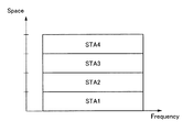
OFDMAは、1つまたは複数のサブキャリアを含む複数のリソースユニットを複数の端末にそれぞれ割り当て、基地局と複数の端末との間で同時に送受信を同時に行う方式である。リソースユニットは、通信を行うリソースの最小単位となる周波数成分であり、本実施形態に係るリソースの一例に対応する。 OFDMA is a scheme in which a plurality of resource units including one or a plurality of subcarriers are respectively assigned to a plurality of terminals, and transmission and reception are simultaneously performed between a base station and a plurality of terminals. The resource unit is a frequency component that is a minimum unit of a resource for performing communication, and corresponds to an example of a resource according to the present embodiment.
UL−MU−MIMOとOFDMAのさらなる詳細は、後述する。なお、PHY処理部50は、UL−MU−MIMOとUL−OFDMAを組み合わせた方式に関する処理を行ってもよい。
Further details of UL-MU-MIMO and OFDMA will be described later. Note that the
PHY処理部50は、受信信号に対し、復号(復調および誤り訂正符号の復号等を含む)処理、プリアンブルを含む物理ヘッダ(PHYヘッダ)を取り除く処理などを行って、ペイロードを抽出する。IEEE802.11規格ではこのペイロードをPHY側ではPSDU(physical layer convergence procedure (PLCP) service data unit)と呼んでいる。PHY処理部50は、抽出したペイロードを受信処理部40に渡し、受信処理部40はこれをMACフレームとして扱う。IEEE802.11規格では、このMACフレームを、MPDU(medium access control (MAC) protocol data unit)と呼んでいる。加えて、PHY処理部50は、信号の受信を開始した際に、その旨を受信処理部40に通知し、また信号の受信を終了した際に、その旨を受信処理部40に通知する。また、PHY処理部50は、受信信号が正常に物理パケット(PHYパケット)として復号できた場合(エラーを検出しなければ)、信号の受信終了を通知すると共に、媒体がアイドルであるということを示す信号を、受信処理部40に渡す。PHY処理部50は、受信信号にエラーを検出した場合には、エラー種別に即した適切なエラーコードをもって、受信処理部40にエラーを検出したことを通知する。また、PHY処理部50は、媒体がアイドルになったと判定した時点で、媒体がアイドルであることを示す信号を受信処理部40に通知する。
The
MAC共通処理部20は、上位処理部90から送信処理部30への送信データの受け渡し、及び受信処理部40から上位処理部90への受信データの受け渡しを、夫々仲介する。IEEE802.11規格では、MACデータフレームの中のこのデータを、MSDU(medium access control (MAC) service data unit)と呼んでいる。また、MAC共通処理部20は、MAC/PHY管理部60からの指示を一旦受け取り、当該指示を送信処理部30及び受信処理部40に、それぞれ適したものに変換して出力する。
The MAC
MAC/PHY管理部60は、例えばIEEE802.11規格におけるSME(Station Management Entity)に相当する。その場合、MAC/PHY管理部60とMAC共通処理部20との間のインターフェースは、IEEE802.11規格におけるMLME SAP(MAC subLayer Managament Entity Service Access Point)に相当し、MAC/PHY管理部60とPHY処理部50との間のインターフェースは、IEEE802.11無線LAN(Local Area Network)におけるPLME SAP(Physical Layer Management Entity Service Access Point)に相当する。
The MAC /
なお、図1において、MAC/PHY管理部60は、MAC管理のための機能部とPHY管理のための機能部とが一体であるかのように描かれているが、分けて実装されてもよい。
In FIG. 1, the MAC /
MAC/PHY管理部60は、管理情報ベース(Management Information Base:MIB)を保持する。MIBは、自端末の能力や各種機能が夫々有効か無効かなどの各種情報を保持する。例えば、自端末が、UL−MU(UL−MU−MIMOまたはUL−OFDMA)に対応か否か、また、UL−MU対応の場合にUL−MU能力の有効(オン)/無効(オフ)の情報も保持されていてもよい。MIBを保持・管理するためのメモリは、MAC/PHY管理部60に内包させてもよいし、MAC/PHY管理部60に内包せずに別に設けるようにしてもよい。MIBを保持・管理するためのメモリをMAC/PHY管理部60とは別に設ける場合に、MAC/PHY管理部60は、その別のメモリを参照でき、またメモリ内の書き換え可能なパラメータに関しては書き換えを行うことができる。メモリはSRAM、DRAM等の揮発性メモリでも、NAND、MRAM等の不揮発メモリでもよい。また、メモリでなく、SSDやハードディスク等の記憶装置でもよい。基地局では、非基地局としての他の端末のこれらの情報も、当該端末からの通知により、取得することができる。その場合、MAC/PHY管理部60は、他の端末に関する情報を参照・書き換えが可能になっている。あるいはこれらの他の端末に関する情報を記憶するためのメモリは、MIBとは別に保持・管理するようにしてもよい。その場合、MAC/PHY管理部60あるいはMAC共通処理部20が、その別のメモリを参照・書き換えが可能なようにする。また基地局のMAC/PHY管理部60は、UL−MUの実施にあたり、非基地局としての端末に関する各種の情報、または端末からの要求に基づき、UL−MU用のリソースを同時に割り当てる端末を選定する選定機能も備えていてもよい。また、MAC/PHY管理部60またはMAC処理部10は、送信するMACフレームおよび物理ヘッダに適用する伝送レートを管理してもよい。また基地局のMAC/PHY管理部60は、基地局がサポートするレートセットであるサポートレートセットを定義および管理してもよい。サポートレートセットは、基地局に接続する端末がサポートすることが必須であるレートと、オプションのレートを含んでもよい。
The MAC /
MAC処理部10は、データフレーム、制御フレーム及び管理フレームの3種類のMACフレームを扱い、MAC層において規定される各種処理を行う。ここで、3種類のMACフレームについて説明する。
The
管理フレームは、他の端末との間の通信リンクの管理のために用いられる。管理フレームとしては、例えば、IEEE802.11規格におけるBasic Service Set(BSS)である無線通信グループを形成するために、グループの属性及び同期情報を報知するビーコン(Beacon)フレームがある。また、認証のためにまたは通信リンク確立のために交換されるフレームなどもある。なお、ある端末が、もう一台の端末と互いに無線通信を実施するために必要な情報交換を済ませた状態を、通信リンクが確立していると、ここでは表現する。必要な情報交換として、例えば、自端末が対応する機能(例えばUL−MUへの対応可否、UL−MU能力のオン/オフの情報など)の通知や、方式の設定に関するネゴシエーションなどがある。管理フレームは、送信処理部30が、MAC/PHY管理部60からMAC共通処理部20を介して受けた指示に基づいて生成する。
The management frame is used for managing a communication link with another terminal. As the management frame, for example, there is a beacon (Beacon) frame that broadcasts a group attribute and synchronization information in order to form a wireless communication group that is a Basic Service Set (BSS) in the IEEE 802.11 standard. There are also frames exchanged for authentication or for establishing a communication link. Here, a state in which one terminal has exchanged information necessary for performing wireless communication with another terminal has been described as a communication link being established. Necessary information exchange includes, for example, notification of a function (for example, whether or not UL-MU can be supported, information on ON / OFF of UL-MU capability, etc.) supported by the terminal itself, and negotiation on setting of a method. The management frame is generated by the
管理フレームに関連して、送信処理部30は、他の端末に管理フレームを介して各種情報を通知する通知手段を有する。この管理フレームとしては、例えば端末が基地局との間で認証を行う手順の一つであるアソシエーションプロセスで用いられるAssociation Requestフレームや、あるいはリアエソシエーションプロセスで用いられるReassociation Requestフレームがある。基地局は、非基地局の端末に、UL−MUへの対応可否およびUL−MU能力のオン/オフの情報等を、管理フレームを介して通知してもよい。これに用いる管理フレームとしては、例えばBeaconフレームや、非基地局端末が送信したProbe Requestフレームに対する応答であるProbe Responseフレームがある。基地局は、自装置に接続している端末群をグループ化する機能を有していてもよい。基地局の上記の通知手段は、各端末にそれぞれが属するグループのグループ識別子であるグループIDを、管理フレームを介して通知してもよい。この管理フレームとしては、例えばGroup ID Managementフレームがある。グループIDは、例えばIEEE Std 802.11ac−2013でダウンリンクMU−MIMO(Multi−User Multi−Input Multi−Output)(DL−MU−MIMO)のために規定されたグループID(6ビット)をUL−MUの場合も包含するように拡張したものでもよいし、これとは別の方法で定義したグループIDでもよい。
In connection with the management frame, the
ここでアソシエーションID(AID)について説明する。AIDは、端末が基地局に接続し、基地局下のBSSでデータフレーム交換が行えるようにするためのアソシエーションプロセスで、基地局から割り当てられる端末の識別子(端末識別子)である。アソシエーションプロセスは具体的には、端末から基地局宛てにAssociation Requestフレームを送信し、基地局から端末宛てにAssociation Responseフレームを送信し、Association Responseフレームの中の端末Status Codeフィールドが”0”すなわちsuccessである場合に成功するプロセスである。Association Requestフレーム、Association Responseフレームの双方には、送信端末の通信能力(Capability)が入れられており、それにより、受信した双方が相手の通信能力を把握する。Association Responseフレームの中の端末Status Codeフィールドが”0”すなわちsuccessである場合には、同フレーム中のAIDフィールド(16ビット)からAIDを抽出し、当該フレームの送信先端末のAIDとして使われる。すなわち、この時点で、基地局から端末にAIDが割り当てられたことになり、端末としてはAIDが有効の状態となる。当該基地局が端末との間で接続(Association)している状態では、端末のAIDが有効である。一方、基地局から当該端末にDisassociationフレームを送信し、当該端末が受信すると、あるいは当該端末から基地局にDisassociationフレームを送信すると、当該端末のAIDは無効(null)となる。どの基地局ともアソシエーションプロセスを経ていない状態の端末では当然、AIDは無効である。AIDが無効の状態は、AIDが未指定の状態とも言うこともできる。 Here, the association ID (AID) will be described. The AID is an identifier (terminal identifier) of the terminal assigned by the base station in an association process for connecting the terminal to the base station and exchanging data frames with the BSS under the base station. Specifically, the association process transmits an Association Request frame from the terminal to the base station, transmits an Association Response frame from the base station to the terminal, and sets the terminal Status Code field in the Association Response frame to “0”, ie, success. Is a successful process. In both the Association Request frame and the Association Response frame, the communication capability (Capability) of the transmitting terminal is entered, whereby both the receiving terminals grasp the communication capability of the other party. If the terminal status code field in the association response frame is “0”, that is, success, the AID is extracted from the AID field (16 bits) in the frame and used as the AID of the destination terminal of the frame. That is, at this point, the AID has been assigned to the terminal from the base station, and the AID is valid as a terminal. In a state where the base station is connected to the terminal (Association), the AID of the terminal is valid. On the other hand, when the base station transmits a disassociation frame to the terminal and the terminal receives the disassociation frame, or when the terminal transmits the disassociation frame to the base station, the AID of the terminal becomes invalid (null). The AID is invalid for a terminal that has not gone through the association process with any base station. A state in which the AID is invalid can also be referred to as a state in which the AID is not specified.
受信処理部40は、他の端末から管理フレームを介して各種情報を受信する受信手段を有する。一例として、基地局の受信手段は、非基地局としての端末からUL−MUの対応可否またはその能力のオン/オフの情報を受信してもよい。また、当該非基地局としての端末がレガシー端末(IEEE802.11a/b/g/n/ac規格対応端末など)の場合に、対応可能なチャネル幅(利用可能な最大のチャネル幅)の情報を受信してもよい。当該端末の受信手段は、基地局からUL−MU対応可否の情報を受信してもよい。
The
上述した管理フレームを介して送受信する情報の例は、ほんの一例であり、その他種々の情報を、管理フレームを介して、端末(基地局を含む)間で送受信することが可能である。例えばUL−MU対応端末は、自身がUL−MU送信で使用することを希望するリソースに関する情報を、基地局に通知してもよい。この場合、基地局は当該情報に基づき、UL−MU通信のためのリソースの割り当てを各端末に対して行ってもよい。 The example of the information transmitted and received via the management frame described above is only an example, and various other information can be transmitted and received between terminals (including the base station) via the management frame. For example, a UL-MU-compatible terminal may notify the base station of information on resources that the terminal itself desires to use for UL-MU transmission. In this case, the base station may allocate resources for UL-MU communication to each terminal based on the information.
データフレームは、他の端末との間で通信リンクが確立した状態で、データを当該他の端末に送信するために用いられる。例えばユーザのアプリケーション操作によって、端末においてデータが生成され、当該データがデータフレームによって搬送される。具体的には、生成されたデータは、上位処理部90からMAC共通処理部20を介して送信処理部30に渡され、送信処理部30でデータをフレームボディフィールドに入れ、当該フレームボディフィールドにMACヘッダを付加してデータフレームが生成される。そして、PHY処理部50で、データフレームに物理ヘッダを付加して物理パケットが生成され、物理パケットが、アナログ処理部70及びアンテナ80を介して送信される。また、PHY処理部50で物理パケットを受信すると、物理ヘッダに基づき物理層の処理を行ってMACフレーム(ここではデータフレーム)を抽出し、データフレームを受信処理部40に渡す。受信処理部40は、データフレームを受けると(受信したMACフレームがデータフレームであると把握すると)、そのフレームボディフィールドの情報をデータとして抽出し、抽出したデータを、MAC共通処理部20を介して上位処理部90に渡す。この結果、データの書き込み、再生などのアプリケーション上の動作が生じる。
The data frame is used to transmit data to another terminal in a state where a communication link has been established with another terminal. For example, data is generated in the terminal by a user's application operation, and the data is carried by a data frame. Specifically, the generated data is passed from the higher-
制御フレームは、管理フレーム及びデータフレームを、他の無線通信装置との間で送受信(交換)するときの制御のために用いられる。制御フレームとしては、例えば、管理フレーム及びデータフレームの交換を開始する前に、無線媒体を予約するために他の無線通信装置との間で交換するRTS(Request to Send)フレーム、CTS(Clear to Send)フレームなどがある。また、他の制御フレームとして、受信した管理フレーム及びデータフレームの送達確認のための送達確認応答フレームがある。送達確認応答フレームの例として、ACK(Acknowledgement)フレーム、BA(Block Ack)フレームなどがある。CTSフレームも、RTSフレームの応答として送信するため、送達確認応答を表すフレームであるとも言える。CF−Endフレームも、制御フレームの1つである。CF−Endフレームは、CFP(Contention Free Period)あるいはアクセス権(送信権)獲得後、媒体を占有可能な時間を表すTXOP(Transmission Opportunity;TXOP)の終了をアナウンスするフレーム、つまり、無線媒体へのアクセスを許可するフレームである。これらの制御フレームは送信処理部30で生成される。受信したMACフレームへの応答として送信される制御フレーム(CTSフレームやACKフレーム、BAフレームなど)に関しては、受信処理部40で応答フレーム(制御フレーム)の送信の必要を判断して、フレーム生成に必要な情報(制御フレームの種別、RA(Receiver Address)フィールド等に設定する情報など)を送信指示とともに送信処理部30に出す。送信処理部30は、当該フレーム生成に必要な情報と送信指示に基づき、適切な制御フレームを生成する。
The control frame is used for controlling transmission and reception (exchange) of the management frame and the data frame with another wireless communication device. As the control frame, for example, before starting exchange of a management frame and a data frame, an RTS (Request to Send) frame exchanged with another wireless communication device to reserve a wireless medium, a CTS (Clear to Send) Send) frame. Other control frames include a delivery confirmation response frame for confirming delivery of the received management frame and data frame. Examples of the delivery confirmation response frame include an ACK (Acknowledgment) frame, a BA (Block Ack) frame, and the like. Since the CTS frame is also transmitted as a response to the RTS frame, it can be said that the CTS frame is a frame indicating a delivery confirmation response. The CF-End frame is also one of the control frames. The CF-End frame is a frame that announces the end of TXOP (Transmission Opportunity; TXOP) indicating the time during which the medium can be occupied after acquiring a CFP (Contention Free Period) or an access right (transmission right), that is, a frame to the wireless medium. This is a frame that permits access. These control frames are generated by the
MAC処理部10は、CSMA/CA(Carrier Sense Multiple Access with Carrier Avoidance)に基づきMACフレームを送信する場合、無線媒体上でのアクセス権(送信権)を獲得する必要がある。送信処理部30は、受信処理部40からのキャリアセンス情報に基づいて、送信タイミングを計る。送信処理部30は、係る送信タイミングに従って、PHY処理部50に送信指示を与えて、さらにMACフレームを渡す。送信指示に加えて、送信処理部30は、送信に使用される変調方式及び符号化方式を合わせて指示してもよい。これらに加えて、送信処理部30は、送信電力を指示してもよい。MAC処理部10は、アクセス権(送信権)獲得後、媒体を占有可能な時間を表すTXOP(Transmission Opportunity;TXOP)が得られると、QoS(Quality of Service)属性などの制限を伴うものの、他の無線通信装置との間でMACフレームを連続して交換できる。TXOPは、例えば、無線通信装置がCSMA/CAに基づき所定のフレーム(例えばRTSフレーム)を送信し、他の無線通信装置から応答フレーム(例えばCTSフレーム)を正しく受信した場合に、獲得される。この所定のフレームが、当該他の無線通信装置によって受信されると、当該他の無線通信装置は、最小フレーム間隔(Short InterFrame Space;SIFS)後に、上記応答フレームを送信する。また、RTSフレームを用いないでTXOPを獲得する方法として、例えば直接ユニキャストで、送達確認応答フレームの送信を要求するデータフレーム(後述のようにフレームが連接された形状のフレーム、またはペイロードが連接された形状のフレームであってもよい)あるいは管理フレームを送信し、それに対する送達確認応答フレーム(ACKフレームやBlockACKフレーム)を正しく受信する場合がある。あるいは、他の無線通信装置に送達確認応答フレームの送信を要求しないフレームであって、そのフレームのDuration/IDフィールドに当該フレームの送信に要する時間以上の期間を設定したものを送信した場合には、当該フレームを送信した段階からDuration/IDフィールドに記載された期間の使用権を獲得したと解釈してもよい。
When transmitting the MAC frame based on CSMA / CA (Carrier Sense Multiple Access with Carrier Aviidance), the
受信処理部40は、上述したキャリアセンス情報を管理する。このキャリアセンス情報は、PHY処理部50から入力される媒体(CCA)のビジー/アイドルに関する物理的なキャリアセンス(Physical Carrier Sense)情報と、受信フレームの中に記載されている媒体予約時間に基づく仮想的なキャリアセンス(Virtual Carrier Sense)情報との両方を包含する。いずれか一方のキャリアセンス情報がビジーを示すならば、媒体がビジーであるとみなされ、その間送信は禁止される。なお、IEEE802.11規格において、媒体予約時間は、MACヘッダの中のDuration/IDフィールドに記載される。MAC処理部10は、他の無線通信装置宛ての(自己宛てでない)MACフレームを受信した場合に、当該MACフレームを含む物理パケットの終わりから媒体予約時間に亘って、媒体が仮想的にビジーであると判定する。このような仮想的に媒体をビジーであると判定する仕組み、或いは、仮想的に媒体をビジーであるとする期間は、NAV(Network Allocation Vector)と呼ばれる。媒体予約時間は無線媒体へのアクセスの抑制を指示する期間の長さ、すなわち無線媒体へのアクセスを延期させる期間の長さを表しているといえる。
The
受信処理部40は、キャリアセンス情報に基づき無線媒体へのアクセスを管理する。MACフレームを送信する場合は、キャリアセンス情報に基づき、バックオフアルゴリズムを利用して、無線媒体の状態を判定し、無線媒体がアイドル状態であれば、アクセス権を獲得し、送信処理部30を用いて、MACフレームを送信する。また、受信処理部40は、アクセスカテゴリ(AC)を利用した優先制御であるEDCA(Enhanced Distributed Channel Access)を実行する。EDCAではACごとに、EDCAパラメータとして、コンテンションウィンドウの最小値CWmin、最大値CWmax、AIFSN(AIFS Number)、およびTXOPリミット(TXOPの上限値)が定義されている。本実施形態では、これらのパラメータを、UL−MU送信の履歴、またはUL−MU送信の能力の有効または無効の設定状態に応じて、変更するよう制御することを特徴の1つとする。UL−MU送信の履歴は、一例として、UL−MU送信の実行有無、UL−MU送信の実行回数、およびUL−MU送信の成功または失敗の実行結果、UL−MU送信(例えば基準となるUL−MU送信、所定の時点で行ったUL−MU送信など)からの経過時間のうちの少なくとも1つを含む。なお、EDCAパラメータの制御は、受信処理部40でなく、MAC/PHY管理部60で行ってもよいし、MAC処理部10内の別の処理回路が行ってもよい。なお、EDCAおよびEDCAパラメータの詳細は後述する。
The
ここで、データフレームは、複数のMACフレームもしくは複数のMACフレームのペイロード部分を連接するようになっていてもよい。前者はIEEE802.11規格ではA(Aggregate)−MPDU、後者はA(Aggregate)−MSDU(MAC service data unit)と呼ばれる。A−MPDUの場合は、PSDUの中に複数のMPDUが連接されることになる。またデータフレームのみならず、管理フレームや制御フレームも連接対象となる。A−MSDUの場合には、1つのMPDUのフレームボディ中に、複数のデータペイロードであるMSDUが連接されることになる。A−MPDU、およびA−MSDUのいずれも、複数のMPDUの連接、および複数のMSDUの連接を、受信側端末で適切に分離できるように、データフレームに区切り情報(長さ情報など)が格納されている。A−MPDUおよびA−MSDUの両方を組み合わせて用いてもよい。またA−MPDUは、複数のMACフレームではなく、1つのMACフレームのみを対象としてもよく、この場合も区切り情報をデータフレームに格納する。また、A−MPDUなどを受信した場合は、連接されている複数のMACフレームに対する応答をまとめて送信する。この場合の応答には、ACKフレームではなく、BA(Block Ack)フレームが用いられる。以降の説明および図では、MPDUの表記を用いることがあるが、これは、上述したA−MPDUまたはA−MSDUの場合も含むものとする。 Here, the data frame may be configured to connect a plurality of MAC frames or a payload portion of the plurality of MAC frames. The former is called A (Aggregate) -MPDU in the IEEE802.11 standard, and the latter is called A (Aggregate) -MSDU (MAC service data unit). In the case of the A-MPDU, a plurality of MPDUs are connected in the PSDU. Not only data frames but also management frames and control frames are connected. In the case of A-MSDU, a plurality of data payloads, that is, MSDUs, are concatenated in the frame body of one MPDU. In each of the A-MPDU and the A-MSDU, delimiter information (length information, etc.) is stored in a data frame so that the connection of a plurality of MPDUs and the connection of a plurality of MSDUs can be appropriately separated at a receiving terminal. Have been. Both A-MPDU and A-MSDU may be used in combination. Also, the A-MPDU may target only one MAC frame instead of a plurality of MAC frames, and in this case, the delimiter information is stored in the data frame. When an A-MPDU or the like is received, responses to a plurality of connected MAC frames are transmitted together. In this case, a BA (Block Ack) frame is used for the response instead of the ACK frame. In the following description and figures, the notation of MPDU may be used, but this also includes the case of A-MPDU or A-MSDU described above.
IEEE802.11規格では、基地局が中心となり構成するBSS(これをインフラストラクチャ(Infrastructure)BSSと呼ぶ)に、非基地局の端末が加入し、BSS内でデータフレームの交換ができるようになるために経る手順(procedure)が、段階的に複数規定されている。例えば、アソシエーション(association)という手順があり、非基地局の端末から、当該端末が接続を要求する基地局に対して、アソシエーション要求(Association Request)フレームを送信する。基地局は、アソシエーション要求フレームに対するACKフレームを送信後、アソシエーション要求フレームに対する応答であるアソシエーション応答(Association Response)フレームを送信する。 According to the IEEE 802.11 standard, a non-base station terminal joins a BSS (referred to as an infrastructure BSS) composed mainly of a base station so that data frames can be exchanged within the BSS. A plurality of procedures are defined in stages. For example, there is a procedure called an association, in which a terminal of a non-base station transmits an association request frame to a base station to which the terminal requests connection. After transmitting the ACK frame for the association request frame, the base station transmits an association response (Association Response) frame, which is a response to the association request frame.
端末はアソシエーション要求フレームに自端末の能力(capability)を格納し、それを送信することで基地局に自端末の能力の通知をすることができる。例えば、端末はアソシエーション要求フレームの中に、自端末が対応可能なチャネルまたはリソースユニットまたはこれらの両方や、自端末が対応する規格を特定するための情報を入れて送信してもよい。他の基地局へ再接続するための再アソシエーション(reassociation)という手順で送信するフレームにも、この情報を設定するようにしてもよい。この再アソシエーションの手順では、端末から、再接続を要求する他の基地局に対して、再アソシエーション要求(Reassociation Request)フレームを送信する。当該他の基地局は、再アソシエーション要求フレームに対するACKフレームを送信後、再アソシエーション要求フレームに対する応答である再アソシエーション応答(Reassociation Response)フレームを送信する。 A terminal can store its capability (capability) in an association request frame and transmit it to notify the base station of the capability of the terminal. For example, the terminal may transmit a channel and / or a resource unit that can be supported by the terminal itself, or information for specifying a standard that the terminal supports, in the association request frame. This information may be set in a frame to be transmitted in a procedure called reassociation for reconnecting to another base station. In this re-association procedure, a terminal transmits a re-association request (Reassociation Request) frame to another base station requesting re-connection. After transmitting the ACK frame for the reassociation request frame, the other base station transmits a reassociation response (Reassociation Response) frame that is a response to the reassociation request frame.
管理フレームとして、アソシエーション要求フレームおよび再アソシエーション要求フレーム以外にも、ビーコンフレーム、プローブ応答(Probe Response)フレームなどを用いてもよい。ビーコンフレームは基本的に基地局が送信するもので、BSSの属性を示すパラメータとともに、基地局自身の能力を通知するパラメータも格納できる。そこで、この基地局自身の能力を通知するパラメータとして、基地局がUL−MUへの対応可否またはその能力のオン/オフの情報を加えるようにしてもよい。また他のパラメータとして、基地局のサポートレート(Supported Rate)の情報を通知してもよい。サポートレートは、基地局が形成するBSSに参加する端末が対応必須のレートと、オプションのレートとを含んでもよい。プローブ応答フレームは、ビーコンフレームを送信する端末からプローブ要求(Probe Request)フレームを受信すると、それに応答して送信するフレームである。プローブ応答フレームは、基本的にはビーコンフレームと同一の内容を通知するものであるため、プローブ応答フレームを用いても基地局は、プローブ要求フレームを送信した端末に、自局の能力を通知することができる。UL−MU対応端末にこの通知を行うことで、端末が例えば自端末のUL−MU通信の機能を有効にするといった動作を行ってもよい。 As the management frame, a beacon frame, a probe response (Probe Response) frame, or the like may be used in addition to the association request frame and the re-association request frame. The beacon frame is basically transmitted by the base station, and can store not only a parameter indicating the attribute of the BSS but also a parameter for notifying the capability of the base station itself. Therefore, as a parameter for notifying the capability of the base station itself, the base station may add information on whether the base station can handle UL-MU or on / off of the capability. Further, as another parameter, information of a supported rate (Supported Rate) of the base station may be notified. The support rate may include a rate mandatory for a terminal participating in the BSS formed by the base station and an optional rate. The probe response frame is a frame transmitted in response to receiving a probe request (Probe Request) frame from a terminal transmitting a beacon frame. Since the probe response frame basically notifies the same contents as the beacon frame, even if the probe response frame is used, the base station notifies the terminal that transmitted the probe request frame of the capability of the own station. be able to. By transmitting the notification to the UL-MU compatible terminal, the terminal may perform an operation of, for example, enabling the function of the UL-MU communication of the terminal itself.
なお、端末は自端末の能力について基地局へ通知する情報として、基地局のサポートレートのうち自端末が実行可能なレートの情報を通知してもよい。ただし、サポートレートのうち必須のレートについては、基地局へ接続する端末はその必須のレートを実行する能力を有するものとする。 In addition, the terminal may notify information of a rate executable by the terminal among the support rates of the base station, as the information to notify the base station of the capability of the terminal. However, as for the mandatory rate among the support rates, the terminal connected to the base station shall have the ability to execute the mandatory rate.
なお、上記で扱った情報のうち、ある情報を通知することで、別の情報の内容が決まるものがあれば、通知を省略できる。例えば、ある新しい規格あるいは仕様に対応する能力を定義し、それに対応していれば自ずとUL−MU対応端末である、という場合を考える。この場合、上記ある情報として、規格あるいは仕様に対応する能力の有を通知し、上記別の情報として、UL−MU対応端末であることの通知を明示的に行わなくてもよい。 It should be noted that among the information handled above, if there is information that determines the content of another information by notifying the certain information, the notification can be omitted. For example, consider a case in which a capability corresponding to a certain new standard or specification is defined, and if the terminal supports the capability, the terminal is naturally a UL-MU compatible terminal. In this case, it is not necessary to explicitly notify the presence or absence of the capability corresponding to the standard or the specification as the certain information, and to explicitly notify the terminal that the terminal is a UL-MU compatible terminal as the other information.
図2に、本実施形態に従った無線通信システムを示す。このシステムは、基地局(AP:Access Point)100と、複数の端末(STA:STAtion)1〜8とを備える。基地局100と、配下の端末1〜8により、BSS(Basic Service Set)1が形成される。このシステムは、CSMA/CA(Carrier Sense Multiple Access with Carrier Avoidance)を用いるIEEE802.11規格に準じた無線LANシステムである。端末1〜8には、少なくとも複数のUL−MU対応端末(以下、HE(High Efficiency)端末と呼ぶ場合もある)が含まれ、これ以外のレガシー端末が含まれてもよい。レガシー端末には、QoSに対応しているがUL−MUに対応していないNon−HE端末と、QoSおよびUL−MUのいずれにも対応していないNon−QoS端末がある。レガシー端末とは、具体的には、IEEE802.11a/b/g/n/ac規格対応端末などである。UL−MU対応端末は、基地局100との間で、UL−MU−MIMOまたはUL−OFDMA等のUL−MU通信が可能である。
FIG. 2 shows a wireless communication system according to the present embodiment. This system includes a base station (AP: Access Point) 100 and a plurality of terminals (STAs: STAs) 1 to 8. A BSS (Basic Service Set) 1 is formed by the base station 100 and the
図3(A)は、MACフレームの基本的なフォーマット例を示す。本実施形態に係るデータフレーム、管理フレームおよび制御フレームは、このようなフレームフォーマットをベースとする。本フレームフォーマットは、MACヘッダ(MAC header)、フレームボディ(Frame body)及びFCSの各フィールドを含む。MACヘッダは、図3(B)に示すように、Frame Control、Duration/ID、Address1、Address2、Address3、 Sequence Control、QoS Control及び HT(High Throughput) controlの各フィールドを含む。
FIG. 3A shows a basic format example of a MAC frame. The data frame, the management frame, and the control frame according to the present embodiment are based on such a frame format. This frame format includes a MAC header (MAC header), a frame body (Frame body), and FCS fields. 3B, the MAC header includes Frame Control, Duration / ID,
これらのフィールドは必ずしもすべて存在する必要はなく、一部のフィールドが存在しない場合もあり得る。例えばAddress3フィールドが存在しない場合もある。また、QoS ControlおよびHT Controlフィールドの両方または一方が存在しない場合もある。またフレームボディフィールドが存在しない場合もあり得る。また図3には示されていない他のフィールドが存在してもよい。例えば、Address4フィールドがさらに存在してもよい。後述するトリガーフレームの場合、共通情報フィールドおよび端末情報フィールドが、フレームボディフィールドまたはMACヘッダに存在してもよい。
Not all of these fields need be present, and some fields may not be present. For example, the
Address1のフィールドには、受信先アドレス(Receiver Address;RA)が、Address2のフィールドには送信元アドレス(Transmitter Address;TA)が入り、Address3のフィールドにはフレームの用途に応じてBSSの識別子であるBSSID(Basic Service Set IDentifier)か、あるいはTAが入る。BSSIDは、全てのBSSIDを対象とするwildcard BSSID(全てのビットが1)の場合もある。
The
Frame Controlフィールドには、タイプ(Type)、サブタイプ(Subtype)という2つのフィールド等が含まれる。データフレームか、管理フレームか、制御フレームかの大別はTypeフィールドで行われ、大別されたフレームの中での細かい種別はSubtypeフィールドで行われる。例えば制御フレームには、BA(Block Ack)フレーム、BAR(Block Ack Request)フレーム、RTS(Request to Send)フレーム、CTS(Clear to Send)フレームといったフレームが存在するが、これらのフレームの識別はSubtypeフィールドで行われる。後述するトリガーフレームも、タイプおよびサブタイプの組み合わせで区別してもよい。一例としてトリガーフレームは制御フレーム(タイプが“制御”)に分類される。 The Frame Control field includes two fields, such as a type (Type) and a subtype (Subtype). A data frame, a management frame, or a control frame is roughly classified in a Type field, and a detailed classification in a roughly classified frame is performed in a Subtype field. For example, control frames include frames such as a BA (Block Ack) frame, a BAR (Block Ack Request) frame, an RTS (Request to Send) frame, and a CTS (Clear to Send) frame, and these frames are identified by Subtype. Done in the field. Trigger frames to be described later may also be distinguished by combinations of types and subtypes. As an example, the trigger frame is classified as a control frame (type is “control”).
Duration/IDフィールドは媒体予約時間を記載し、他の端末宛てのMACフレームを受信した場合に、当該MACフレームを含む物理パケットの終わりから媒体予約時間に亘って、媒体が仮想的にビジーであると判定する。このような仮想的に媒体をビジーであると判定する仕組み、或いは、仮想的に媒体をビジーであるとする期間は、前述したように、NAV(Network Allocation Vector)と呼ばれる。QoSフィールドは、フレームの優先度を考慮して送信を行うQoS制御を行うために用いられる。HT Controlフィールドは、IEEE802.11nで導入されたフィールドである。HT(High Throughput) Controlフィールドは、QoSデータあるいは管理フレームのときに、オーダーフィールドが1に設定されていると存在するものである。HT ControlフィールドはVHT (Very High Throughput) Controlフィールドにも、HE (High Efficient) Controlフィールドにも拡張可能で、各々IEEE802.11n、IEEE802.11ac、あるいはIEEE802.11axの各種機能に応じた通知をすることができる。 The Duration / ID field describes the medium reservation time, and when a MAC frame addressed to another terminal is received, the medium is virtually busy from the end of the physical packet including the MAC frame to the medium reservation time. Is determined. Such a mechanism for virtually determining that the medium is busy, or a period in which the medium is virtually busy, is referred to as a NAV (Network Allocation Vector), as described above. The QoS field is used for performing QoS control for performing transmission in consideration of the priority of the frame. The HT Control field is a field introduced in IEEE 802.11n. An HT (High Throughput) Control field exists when the order field is set to 1 in the case of QoS data or a management frame. The HT Control field can be extended to a VHT (Very High Throughput) Control field or an HE (High Efficient) Control field, and various functions of notifying IEEE802.11n, IEEE802.11ac, or IEEE802.11ax, respectively. be able to.
管理フレームでは、固有のElement ID(IDentifier)が割り当てられた情報エレメント(Information element;IE)をFrame Bodyフィールドに設定する。フレームボディフィールドには、管理フレームの種類に応じた固有のフィールドの後に、1つまたは複数の情報エレメントを設定できる。情報エレメントは、図4に示すように、Element IDフィールド、Lengthフィールド、情報(Information)フィールドの各フィールドを有する。情報エレメントは、Element IDで識別される。情報フィールドは、通知する情報の内容を格納し、Lengthフィールドは、情報フィールドの長さ情報を格納する。 In the management frame, an information element (Information element; IE) to which a unique Element ID (IDentifier) is assigned is set in the Frame Body field. In the frame body field, one or more information elements can be set after a field specific to the type of the management frame. As shown in FIG. 4, the information element has an Element ID field, a Length field, and an information (Information) field. An information element is identified by an Element ID. The information field stores the content of the information to be notified, and the Length field stores the length information of the information field.
FCSフィールドには、受信側でフレームの誤り検出のため用いられるチェックサム符号としてFCS(Frame Check Sequence)情報が設定される。FCS情報の例としては、CRC(Cyclic Redundancy Code)などがある。 In the FCS field, FCS (Frame Check Sequence) information is set as a checksum code used for detecting a frame error on the receiving side. Examples of the FCS information include a CRC (Cyclic Redundancy Code).
(本実施形態の第1の動作例)
図5に、本実施形態に係る基地局(AP)101と、端末(STA)1〜端末8との動作シーケンスの第1の例を示す。図では端末1〜8のうち、端末1と端末2のみが示されている。端末1〜4はHE端末であり、端末5〜8は、レガシー端末(Non−HE端末もしくはNon−Qos端末)である場合を想定する。
(First operation example of the present embodiment)
FIG. 5 shows a first example of an operation sequence of the base station (AP) 101 and the terminals (STAs) 1 to 8 according to the present embodiment. In the figure, of the
前提として、基地局と端末1〜8の一部または全部との間でCSMA/CAベースで個別に通信(シングルユーザ通信)が行われている。シングルユーザ通信では、例えば基本チャネル幅(例えば20MHz)の1チャネルで、基地局および端末間で個別に通信が行われている。シングルユーザ通信の例として、端末でアップリンク送信用のデータが保持されている場合、CSMA/CAに従って、無線媒体へのアクセス権を獲得する。このため、端末は固定時間であるDIFS/AIFSと、ランダムに決定したバックオフ時間との合計であるキャリアセンス時間(待機時間)の間、キャリアセンスを行い、媒体(CCA)がアイドルであると判断されると、媒体へのアクセス権を獲得する。端末は、送信するデータを含むデータフレーム(より詳細にはデータフレームを含む物理パケット)を送信する。データフレームのRAは基地局のMACアドレス(すなわちBSSID)、TAは、端末のMACアドレスである。基地局がこのデータフレームを正常に受信すると、データフレームの受信完了からSIFS後に、送達確認応答フレームであるACKフレーム(より詳細にはACKフレームを含む物理パケット)を返す。端末はACKフレームを受信することで、データフレームの送信が成功したと判断する。なお、基地局に送信するデータフレームはアグリゲーションフレーム(A−MPDU等)でもよく、基地局が応答する送達確認応答フレームはBAフレームでもよい(以下同様)。
As a premise, communication (single-user communication) is performed individually between the base station and some or all of the
DIFS/AIFSは、DIFSおよびAIFSのいずれか一方の時間を意味する。QoS対応でない場合はDIFSを指し、QoS対応の場合は、送信するデータのアクセスカテゴリ(AC:Access Category)に応じて決まるAIFS(以下、AIFS[AC]と記述する場合がある)を指す。なお、物理パケットの基本的な構成は、データフィールドに格納されるMACフレームに、物理ヘッダを付加したものである。物理ヘッダは、一例として、図6に示すように、IEEE802.11規格で定義されているL−STF(Legacy−Short Training Field)、L−LTF(Legacy−Long TrainingField)、L−SIG(Legacy Signal Field)、を含む。L−STF、L−LTF、L−SIGは、例えば、IEEE802.11aなどのレガシー規格の端末が認識可能なフィールドであり、それぞれ信号検出、周波数補正(伝搬路推定)、伝送速度(伝送レート)などの情報が格納される。ここで述べた以外のフィールド(例えばレガシー規格の端末が認識できず、UL−MU対応端末が認識できるフィールド)が含まれてもよい。例えばIEEE802.11axで検討されているHE−SIG−A(およびHE−SIG−B)、HE−STFおよびHE−LTFなどが入ってもよい。 DIFS / AIFS means one of DIFS and AIFS. In the case of not supporting QoS, it indicates DIFS. In the case of supporting QoS, it indicates AIFS (hereinafter sometimes referred to as AIFS [AC]) determined according to an access category (AC) of data to be transmitted. The basic configuration of a physical packet is obtained by adding a physical header to a MAC frame stored in a data field. As an example, as shown in FIG. 6, the physical header is L-STF (Legacy-Short Training Field), L-LTF (Legacy-Long Training Field), L-SIG (Legacy Signal) defined in the IEEE 802.11 standard. Field). L-STF, L-LTF, and L-SIG are fields that can be recognized by a terminal of a legacy standard such as IEEE802.11a, for example, and include signal detection, frequency correction (propagation estimation), and transmission speed (transmission rate). Is stored. Fields other than those described here (for example, fields that cannot be recognized by legacy-standard terminals and can be recognized by UL-MU compatible terminals) may be included. For example, HE-SIG-A (and HE-SIG-B), HE-STF, HE-LTF, and the like, which are considered in IEEE 802.11ax, may be included.
ここで、上記のバックオフ時間は、0から整数で与えられるコンテンションウィンドウ(Contention Window:CW)からランダムに選択される整数に、スロット時間(例えば9μs)をかけたものである。CWの初期値は、最小値(CWmin)であり、再送するたびにCWの値は、最大値(CWmax)になるまで段階的に増やされる。CWminとCWmaxの両方とも、AIFSと同様、AC(アクセスカテゴリ)ごとの値を持つ。 Here, the above-mentioned back-off time is obtained by multiplying an integer randomly selected from a contention window (CW) given as an integer from 0 by a slot time (for example, 9 μs). The initial value of the CW is a minimum value (CWmin), and the value of the CW is increased stepwise until the maximum value (CWmax) is reached each time retransmission is performed. Both CWmin and CWmax have a value for each AC (access category), similar to AIFS.
ACを利用した優先制御方式としてEDCA(Enhanced Distributed Channel Access)がある。EDCAについて簡単に説明する。IEEE802.11規格の無線LANでは、上位層(LLC層等)からMAC層にデータが渡される際に、端末がQoS(Quality of Service)に対応する場合には、データとともにトラヒック種別(TID)が通知される。なお既存の規格ではIEEE802.11nやIEEE802.11acの対応端末は、QoSに対応する。 There is EDCA (Enhanced Distributed Channel Access) as a priority control method using AC. EDCA will be briefly described. In a wireless LAN of the IEEE 802.11 standard, when data is passed from an upper layer (such as an LLC layer) to a MAC layer and a terminal supports QoS (Quality of Service), a traffic type (TID) is included together with the data when the terminal supports QoS (Quality of Service). Notified. In the existing standard, a terminal supporting IEEE802.11n or IEEE802.11ac supports QoS.
当該データは、例えばトラヒック種別に基づいて、4つのACに分類される。一例として、TIDの値は、0〜15まで存在し、0〜7はEDCA環境にある端末(基地局を含む)で使用され、8〜15はHCCA(hybrid coordination function (HCF) controlled channel access (HCCA))環境あるいはHEMM(HCCA、EDCA mixed mode)環境にある端末(基地局を含む)で使用される。ここではEDCA環境を想定し、TIDの値が0〜7のいずれであるかに応じて、4つのACのいずれか1つに分類される。 The data is classified into four ACs based on, for example, a traffic type. As an example, the values of TID exist from 0 to 15, 0 to 7 are used by terminals (including base stations) in an EDCA environment, and 8 to 15 are hybrid coordinated function (HCF) controlled channel access (HCCA). HCCA)) or a terminal (including a base station) in a HEMM (HCCA, EDCA mixed mode) environment. Here, assuming an EDCA environment, the TID is classified into any one of the four ACs depending on whether the value of the TID is 0 to 7.
ACの種類として、BACKGROUND(AC_BK)、BEST EFFORT(AC_BE)、VIDEO(AC_VI)、VOICE(AC_VO)が定められている。各ACの優先度は低い方から順にAC_BK、AC_BE、AC_VI、AC_VOである。4つのACに対して送信バッファ(送信キュー)がそれぞれ設けられ、分類されたデータは、該当する送信バッファに格納される。送信バッファは、メモリでもよいし、SSD、ハードディスク等でもよい。送信バッファがメモリの場合、当該メモリはDRAM、SRAM等の揮発性メモリでも、NAND、MRAM等の不揮発メモリでもよい。 BACKGROUND (AC_BK), BEST EFFORT (AC_BE), VIDEO (AC_VI), and VOICE (AC_VO) are defined as types of AC. The priority of each AC is AC_BK, AC_BE, AC_VI, AC_VO in order from the lowest. A transmission buffer (transmission queue) is provided for each of the four ACs, and the classified data is stored in the corresponding transmission buffer. The transmission buffer may be a memory, an SSD, a hard disk, or the like. When the transmission buffer is a memory, the memory may be a volatile memory such as a DRAM or an SRAM, or a nonvolatile memory such as a NAND or an MRAM.
各ACには、複数のEDCAパラメータが定められており、このパラメータで送信時の媒体アクセスの優先度の差が決定される。パラメータの例としては、CWmin、CWmax、AIFSN、およびTXOPリミット(Max TXOP)などがある。CWminおよびCWmaxは、CWの最小値および最大値である。AIFSNは、AIFS Numberのことであり、AIFSの時間長に対応する。TXOPリミットは、獲得可能なTXOPの上限値(最大値)を表す。AIFSN、CWminおよびCWmaxは、媒体アクセスの優先度の高いACほど、小さい値に設定される。逆にTXOPリミットは、媒体アクセスの優先度の高いACほど、大きい値に設定される傾向にあるが、但しAC_VIの方がAC_VOよりも基本的に大きい値となる。これはトラヒック種別の特性を考慮したものである。 A plurality of EDCA parameters are defined for each AC, and these parameters determine the difference in the priority of medium access during transmission. Examples of parameters include CWmin, CWmax, AIFSN, and TXOP limit (Max TXOP). CWmin and CWmax are the minimum and maximum values of CW. AIFSN is AIFS Number and corresponds to the AIFS time length. The TXOP limit indicates an upper limit (maximum value) of a TXOP that can be obtained. AIFSN, CWmin, and CWmax are set to smaller values for ACs with higher medium access priorities. Conversely, the TXOP limit tends to be set to a larger value for an AC with a higher medium access priority, but the AC_VI is basically a larger value than the AC_VO. This takes into account the characteristics of the traffic type.
図7に、アクセスカテゴリごとの複数のEDCAパラメータの値の例を示す。QoS対応でない場合(Non−QoS端末の場合)、便宜上、アクセスカテゴリをLegacy DCF(Distributed Coordination Function)と表記している。DCFとはEDCAと類似するが、QoS制御(ACに基づく優先制御)の概念がないアクセス方式である。Max TXOP(TXOPリミット)の値が0の場合、1フレーム(より詳細には1MSDU)のみ送信可能であることを意味する。図7のEDCAパラメータの値はデフォルト値であり、EDCAパラメータの値は、基地局(BSS)ごとに事前に設定することも可能である。本実施形態では、図示のデフォルトのEDCAパラメータ値または基地局が事前に設定したEDCAパラメータ値を、通常のEDCAパラメータ値と呼ぶ。例えば図示のTXOPリミット値は、通常のTXOPリミット値と呼ぶことがある。 FIG. 7 shows an example of values of a plurality of EDCA parameters for each access category. If the terminal does not support QoS (in the case of a Non-QoS terminal), the access category is described as Legacy DCF (Distributed Coordination Function) for convenience. DCF is an access method similar to EDCA but without the concept of QoS control (priority control based on AC). When the value of Max TXOP (TXOP limit) is 0, it means that only one frame (more specifically, one MSDU) can be transmitted. The value of the EDCA parameter in FIG. 7 is a default value, and the value of the EDCA parameter can be set in advance for each base station (BSS). In the present embodiment, the illustrated default EDCA parameter value or the EDCA parameter value preset by the base station is referred to as a normal EDCA parameter value. For example, the illustrated TXOP limit value may be referred to as a normal TXOP limit value.
EDCA環境では、端末(HE端末およびQoS端末)では、CSMA/CAに基づくデータ送信のための手順が、送信用のデータを有するACごとに独立して行われる。すなわち、ACごとに、ACの種類に応じたAIFS[AC]と、バックオフ時間とを含む待機時間の間、キャリアセンスを行い、最初に待機時間がゼロになったACが、アクセス権を獲得する。待機時間が同時にゼロになったACが複数存在する場合は、媒体アクセスの優先度の高いACがアクセス権を獲得する。なお、Non−QoS端末では、前述したように、DIFSとバックオフ時間とを含む待機時間、キャリアセンスを行い、待機時間の終わりまでの間、媒体(CCA)がアイドルであると判断されると、媒体へのアクセス権を獲得する。 In an EDCA environment, a terminal (HE terminal and QoS terminal) performs a procedure for data transmission based on CSMA / CA independently for each AC having data for transmission. That is, for each AC, carrier sense is performed during the standby time including the AIFS [AC] corresponding to the type of AC and the back-off time, and the AC whose standby time becomes zero first acquires the access right. I do. If there are a plurality of ACs for which the waiting time has become zero at the same time, the AC having the higher priority for medium access acquires the access right. Note that, as described above, the Non-QoS terminal performs the carrier sense for the standby time including the DIFS and the back-off time, and determines that the medium (CCA) is idle until the end of the standby time. , Gain access to media.
図5において、基地局がUL−MUのトリガーフレーム51を送信バッファに保持しているとする。トリガーフレーム51では、UL−MU送信用に複数の端末を指定する情報、各端末がUL−MU送信で利用する各種パラメータの情報などを含む。パラメータの情報の例として、UL−MU送信で利用するリソースの情報、送信パケット長の情報、送信電力等の情報がある。また、UL−MU送信で送信するデータのACを指定または推奨する情報でもよい。当該パラメータの情報は端末ごとに個別に指定されるものと、複数の端末に共通に指定されるものがあってもよい。MACヘッダに設定するRAは、一例として、ブロードキャストアドレスまたはマルチキャストアドレスである。TAは、基地局のMACアドレス(BSSID)である。トリガーフレームのフォーマット例は後述する。
In FIG. 5, it is assumed that the base station holds the UL-
また、端末1がAC_VO(アクセスカテゴリがVoice)のデータ、端末2が、AC_BE(アクセスカテゴリがBestEffort)のデータを、それぞれ該当するACの送信バッファに保持している。基地局、端末1および端末2とも、これらの以外のACについては、データを保持していないとする。トリガーフレームに適用するEDCAパラメータは、最も優先的なACであるVO(Voice)のパラメータの値と同じとする。ただし、トリガーフレームは、他のACのパラメータの値と同じものを用いてもよいし、トリガーフレーム用の値を別途、定義することも可能である。
The
基地局、端末1および端末2は、それぞれACに応じたAIFS[AC]とバックオフ時間との合計である待機時間の間、キャリアセンスを行う。基地局、端末1、端末2のいずれとも、キャリアが検知されることなくAIFS[AC]が経過し、続くバックオフ時間も引き続き、キャリアセンスを行う。バックオフ時間のある時点(t1とする)におけるバックオフカウンタの値の例を図8(A)に示す。時点t1では基地局のバックオフカウンタ(AC_CW)は3、端末1のバックオフカウンタ(EDCA_CW_VO)は4、端末2のバックオフカウンタ(EDCA_CW_BE)は15を指している。したがって、この後、基地局のバックオフカウンタが最も早く0になることが分かる。
Each of the base station, the
キャリアが検知されることなく、基地局のバックオフカウンタが0になると、すなわちバックオフ時間が経過すると、基地局は、無線媒体へのアクセス権を獲得し、トリガーフレーム51を送信する。より詳細には、トリガーフレーム51に物理ヘッダを付加した物理パケットが送信される。トリガーフレーム51は、端末1および端末2(および図示していないその他の端末)で受信される。端末1および端末2は、トリガーフレーム51を運ぶ信号の受信により、キャリアが検知されたと判断し、バックオフ動作を停止する。すなわち、端末1および端末2のバックオフカウンタは停止される。この時点(t2とする)の基地局、端末1および端末2におけるそれぞれのバックオフカウンタの値を、図8(B)に示す。基地局ではカウンタ値が0であり、端末1では1(=4−3)、端末2では12(=15−3)である。
When the backoff counter of the base station reaches 0 without detecting a carrier, that is, when the backoff time elapses, the base station acquires the right to access the wireless medium and transmits the
トリガーフレーム51を受信した端末1および端末2は、トリガーフレーム51で自端末が指定されていることを検知すると、該当するAC用の送信バッファからデータを読み出し、データを含むデータフレームを生成する。そして、当該データフレームに物理ヘッダを付加した物理パケット(PPDU)52、53を、トリガーフレーム51の受信完了から予め定めた時間後にUL−MU送信する。トリガーフレームで、複数の端末に共通の物理パケット長(PPDU長)が指定されている場合、端末1および端末2は、当該指定された長さの物理パケットを生成する。生成するパケット長が当該指定された長さに満たない場合は、パディングデータを末尾に付加することで、物理パケット長を調整する。
When the
予め定めた時間は、SIFSでもよいし、これより大きな値でもよい。UL−MUは、例えば、UL−MU−MIMOまたはUL−OFDMAまたはこれらを組み合わせた方式(UL−MU−MIMO&OFDMA)である。どの方式を用いるかは、BSSで事前に決められていてもよいし、トリガーフレームで指定されていてもよい。 The predetermined time may be SIFS or a larger value. The UL-MU is, for example, UL-MU-MIMO, UL-OFDMA, or a combination thereof (UL-MU-MIMO & OFDMA). Which method is used may be determined in advance by the BSS or may be specified by a trigger frame.
物理パケット52、53を受信した基地局は、これらの物理パケットの受信完了から予め定めた時間(SIFS等)後に、送達確認応答フレーム54を送信する。ここでは、送達確認応答フレームとして、端末1および端末2への送達確認をまとめて含むMulti−STA BAフレーム(以下、M−BAフレーム)54を送信する。M−BAフレームのフォーマット例は後述する。なお、送達確認応答の方法は、M−BAフレームの送信以外の方法でもよい。例えば、端末1および端末2に順次、ACKフレーム(またはBAフレーム)をシングルユーザ送信してもよい。または端末1および端末2にACKフレーム(またはBAフレーム)を、DL−MU送信してもよい。DL−MUは、たとえばDL−MU−MIMOまたはDL−OFDMAまたはこれらを組み合わせた方式(DL−MU−MIMO&OFDMA)である。
The base station that has received the
M−BAフレーム54を受信した端末1および端末2は、M−BAフレーム54に含まれる自端末宛の情報を確認することで、データフレームの送信成功可否を確認する。端末1および端末2は、送信に失敗したと判断した場合は、該当するデータフレームを次回以降の機会で再送することを決定する。ここでは端末1および端末2とも送信に成功した場合を想定する。
The
M−BAフレーム54の送信後、基地局は、送信したいデータまたはフレームを有さず、端末1および端末2は、依然として、それぞれ先ほど送信したデータと同じAC用の送信バッファに、データを保持しているとする。つまり、端末1および端末2は、トリガーフレーム51の受信前のキャリアセンスでアクセス権の獲得対象としていたデータを、UL−MU送信しており、引き続き同じAC用の送信バッファに、送信用のデータを有している。
After transmitting the M-
このため、端末1および端末2は、M−BAフレームの受信完了から予め定めた時間(SIFS等)後に、キャリアセンスを開始する。具体的に、端末1および端末2は、それぞれAIFS[AC]とバックオフ時間との合計である待機時間の間、キャリアセンスを行う。この際、バックオフ時間は、トリガーフレーム51の信号の受信時に停止したときのバックオフカウンタの値(図8(B)参照)が示す時間を用いる。したがって、端末1、端末2のいずれとも、AIFS[AC]が経過した時点でのバックオフカウンタの値は、図8(B)の値となる。したがって、この後、端末1のバックオフカウンタが最も早く0になることが分かる。
Therefore, the
端末1で、キャリアが検知されることなく、バックオフカウンタが0になると、すなわちバックオフ時間が経過すると、端末1は、該当するAC用の送信バッファからデータを読み出してデータフレームを生成し、データフレームを含む物理パケット(PPDU)55を送信する。なお、端末は、データフレームの生成の際、該当するACのTXOPリミット値(図7参照)の範囲内でTXOPを決定し、当該長さからパケット長を引いた値を、MACヘッダのDuration/IDフィールドに設定する。1フレームのみの送信(今回の送信のみ)の場合は、所定値(例えば0)を設定すればよい。
When the back-off counter reaches 0 without detecting a carrier in the
物理パケット55は、基地局で受信され、受信完了からSIFS後に、端末1宛に送達確認応答フレームが送信される。図の例では、BAフレーム56が送信されているが、送信したデータフレームがA−MPDUでなければ、ACKフレームの場合もある。端末2は、物理パケット55を運ぶ信号の受信により、キャリアが検知されたと判断し、バックオフ動作を停止する。すなわち、端末2のバックオフカウンタが停止される。この時点(t3とする)の端末1および端末2におけるそれぞれのバックオフカウンタの値を、図8(C)に示す。基地局では送信するフレームが存在しないため、バックオフカウンタは存在せず(図では、このことをNo Frameと表記している)、端末1では0、端末2では11(=12−1)である。
The
以降も同様にして、シーケンスが継続される。端末2では、次回のキャリアセンス時に、t3時点のバックオフカウンタ値を引き続き用いる。端末1は、さらに送信するデータを有する場合は、該当するACに応じて、新たにCWからランダムに値を選択して、バックオフ時間を算出する。
Thereafter, the sequence is similarly continued. Terminal 2 continues to use the back-off counter value at time t3 at the next carrier sense. When the
上述したシーケンスでは、端末1および端末2ともUL−MU送信に成功したが、失敗した場合も同様にして、バックオフカウンタの値を引き継いでもよい。通常、EDCAでは失敗した場合、バックオフカウンタの値は取り直すが、その際バックオフカウンタを選択するCWの値は、失敗する度、最大値(CWmax)になるまで段階的に増やされる。この通常動作を適用するようにしてもよい。また変形例として、UL−MU送信に失敗した場合は、バックオフカウンタの値を引き継ぎ、成功した場合は、新たにバックオフ時間を決定し直してもよい。
In the above-described sequence, both the
上述したシーケンスでは、トリガーフレーム受信前にバックオフ動作の対象となっていたACと、UL−MU送信の対象となったACが同じであったが、両ACが異なる場合もあり得る。例えばトリガーフレームで推奨または指定されていたACと、バックオフ動作の対象となっていたACが異なる場合がある。その場合も、トリガーフレーム受信時に停止したバックオフカウンタ値を、次回のSU送信用のバックオフ動作に使い回してもよい。なお、トリガーフレームでACが指定されている場合は、端末は、当該ACに属するデータを送信し、当該ACに属するデータが送信バッファに存在しない場合は、UL−MU送信しないか、もしくはデータが存在しない旨の通知を含むフレームを送信してもよい。トリガーフレームでACが推奨されている場合は、可能なかぎり、当該ACに属するデータを送信する。例えば、推奨されるACに属するデータが送信バッファに存在する場合は、そのデータを送信し、存在しない場合は、他のACに属するデータを送信してもよい。 In the above-described sequence, the AC targeted for the back-off operation before receiving the trigger frame is the same as the AC targeted for the UL-MU transmission, but both ACs may be different. For example, the AC recommended or specified in the trigger frame and the AC targeted for the back-off operation may be different. In this case, the back-off counter value stopped at the time of receiving the trigger frame may be reused for the next SU transmission back-off operation. Note that, when AC is specified in the trigger frame, the terminal transmits data belonging to the AC, and when data belonging to the AC does not exist in the transmission buffer, the terminal does not transmit UL-MU, or A frame including a notification that the message does not exist may be transmitted. When the AC is recommended in the trigger frame, data belonging to the AC is transmitted as much as possible. For example, if data belonging to the recommended AC exists in the transmission buffer, the data may be transmitted, and if not, data belonging to another AC may be transmitted.
トリガーフレーム受信前にバックオフ動作の対象となっていたACが複数であり、そのうちの1つが、UL−MU送信の対象となったACである場合も同様に、トリガーフレーム受信時に停止した各AC用のバックオフカウンタ値を、次のバックオフ動作時に使い回してもよい。 Similarly, in the case where there are a plurality of ACs that have been subjected to the back-off operation before receiving the trigger frame, and one of them is the AC that has been subjected to the UL-MU transmission, similarly, May be reused in the next back-off operation.
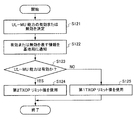
トリガーフレームではUL−MU送信の複数の端末を指定したが、端末の指定を行わず、端末側でランダムに、ランダムアクセスが許可されたリソース群(例えばOFDMAの場合、リソースユニット群)からリソースを選択してUL−MU送信する(ランダムアクセスする)ことを許容するトリガーフレームを用いてもよい。このようなトリガーフレームを、ランダムアクセス用トリガーフレーム:Trigger Frame For Random Access:TF−R)と呼んでもよい。この場合、図9のフローチャートにおいて、トリガーフレームで自端末が指定されたかの判断(図9のS13)を、端末側でランダムアクセスするかの判断に置き換えればよい。そして、ランダムアクセスを行う場合は、図9のステップS14に進むようにすればよい。TF−Rを受信した端末は、ランダムバックオフ手法に類似した方法に基づきリソースを選択する。例えば予めランダムに選択したランダムバックオフカウンタ値から、ランダムアクセスが許可されたリソース数を引き、0以下になると選択権があるとして、リソースの選択を行う。0より大きい場合は、今回のランダムアクセスを見送り、次回のTF−Rの受信時に、減算後のランダムバックオフカウンタ値を利用して、同様にして選択権の有無を判断する。TF−Rおよびランダムアクセスの詳細については後述する。 In the trigger frame, a plurality of terminals for UL-MU transmission are specified. However, the terminals are not specified, and the terminals randomly allocate resources from a resource group (for example, a resource unit group in the case of OFDMA) to which random access is permitted. A trigger frame that allows selection and UL-MU transmission (random access) may be used. Such a trigger frame may be referred to as a trigger frame for random access (Trigger-Frame For Random Access: TF-R). In this case, in the flowchart of FIG. 9, the determination as to whether or not the terminal itself is specified in the trigger frame (S13 in FIG. 9) may be replaced with the determination as to whether or not the terminal performs random access. Then, when performing random access, the process may proceed to step S14 in FIG. The terminal that has received the TF-R selects a resource based on a method similar to the random backoff method. For example, the number of resources for which random access is permitted is subtracted from a random backoff counter value randomly selected in advance. If the value is greater than 0, the current random access is postponed, and the next time the TF-R is received, the presence / absence of the selection right is similarly determined using the subtracted random back-off counter value. Details of TF-R and random access will be described later.
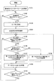
図9は、本実施形態の第1の動作例に係る端末の動作のフローチャートである。 FIG. 9 is a flowchart of the operation of the terminal according to the first operation example of the present embodiment.
端末が、バックオフ動作時に基地局からトリガーフレームを受信すると(S11)、バックオフ動作を停止、すなわちバックオフカウンタを停止する(S12)。このときのバックオフカウンタ値はそのまま維持しておく。つまり、このときのバックオフカウンタ値を記憶装置に記憶しておく。端末は、トリガーフレームに基づき、自端末がUL−MU用に指定されているか判断する(S13)。自端末が指定されている場合は(YES)、該当するAC用の送信バッファからデータを読み出し、当該データを含むデータフレームを生成し、当該データフレームを含む物理パケットを、トリガーフレームの受信完了から予め定めた時間後にUL−MU送信する(S14)。前述したように、データを読み出すACは、バックオフ動作の対象となっていたACの場合、これとは異なるACの場合のいずれもあり得るが、ここではACが同じ場合を想定する。 When the terminal receives the trigger frame from the base station during the back-off operation (S11), the terminal stops the back-off operation, that is, stops the back-off counter (S12). The back-off counter value at this time is kept as it is. That is, the back-off counter value at this time is stored in the storage device. The terminal determines whether the terminal is designated for UL-MU based on the trigger frame (S13). If the own terminal is specified (YES), the data is read from the corresponding AC transmission buffer, a data frame including the data is generated, and the physical packet including the data frame is transmitted after the completion of the trigger frame reception. UL-MU transmission is performed after a predetermined time (S14). As described above, the AC from which data is read may be either the AC that was the target of the back-off operation or a different AC, but it is assumed here that the same AC is used.
端末は、UL−MU送信後、基地局から送信される送達確認応答フレーム(M−BAフレーム等)を受信し、送達確認応答フレームを検査することで、UL−MU送信が成功したかを判断する(S15)。送信に失敗したデータが存在する場合は、次回以降の送信(UL−MU送信またはSU送信)の機会でそのデータを再送することを決定する。 After transmitting the UL-MU, the terminal receives the acknowledgment response frame (M-BA frame or the like) transmitted from the base station and checks the acknowledgment response frame to determine whether the UL-MU transmission is successful. (S15). If there is data that failed to be transmitted, it is determined that the data should be retransmitted at the next transmission (UL-MU transmission or SU transmission).
端末は、トリガーフレームで自端末が指定されていなかった場合(S13のNO)、またはUL−MU送信後もUL送信したいデータが存在する場合(S16のYES)、SU送信用のアクセス権を獲得するため、キャリアセンスを行う。キャリアセンスは、該当するACのEDCAパラメータに応じて、固定時間であるAIFS[AC]と、バックオフ時間との合計である待機時間の間行う。このとき、バックオフ時間は、ステップS12で停止したときのバックオフカウンタ値を用いる(S17)。端末は、キャリアセンスの間、キャリア検知がなければ、無線媒体へのアクセス権を獲得する(S18のYES)。端末は、アクセス権を獲得できた場合は、該当するAC用の送信バッファからデータを読み出してデータフレームを生成し、データフレームを含む物理パケットをSU送信する(S19)。なお、前述したシーケンス例では、端末3、4(HE端末)が、ステップS13において、トリガーフレームで自端末が指定されていなかった端末に相当する。端末5〜8(レガシー端末)は、トリガーフレーム51の受信などでバックオフ動作を停止した場合は、その後、SU送信に成功するまで、キャリアセンス時にバックオフ時間として、直前のバックオフカウンタ値の値を使い回し続ければよい。
The terminal acquires the access right for SU transmission when the terminal itself is not specified in the trigger frame (NO in S13), or when there is data to be transmitted UL even after transmission of the UL-MU (YES in S16). In order to do so, carrier sense is performed. Carrier sensing is performed during a standby time, which is the sum of a fixed time AIFS [AC] and a back-off time, according to the EDCA parameter of the corresponding AC. At this time, the back-off time uses the back-off counter value at the time of stopping in step S12 (S17). If there is no carrier detection during the carrier sense, the terminal acquires the right to access the wireless medium (YES in S18). If the terminal can acquire the access right, the terminal reads data from the corresponding AC transmission buffer, generates a data frame, and transmits the physical packet including the data frame by SU (S19). In the sequence example described above, the
以上、バックオフ動作時にトリガーフレームが受信された場合にバックオフカウンタを停止し、そのときのカウンタ値を、UL−MU送信後に行うシングルユーザ(SU)送信用のバックオフ動作に流用する。一般的な動作であれば、次回のSU送信時に、新たにCWからランダムに値を選択して、バックオフ時間を算出するが、本実施形態では、トリガーフレームの受信時に停止したバックオフカウンタの値を再利用するため、トリガーフレーム受信までに行ったバックオフ動作を無駄にすることを防止できる。UL−MU送信した端末と、それ以外の端末とで無線媒体の使用のフェアネスの問題は存在するものの、EDCA環境でUL−MU送信を行う場合に、UL−MU送信した端末のバックオフ動作が無駄になることを防止できる。 As described above, when the trigger frame is received during the back-off operation, the back-off counter is stopped, and the counter value at that time is used for the back-off operation for single-user (SU) transmission performed after the UL-MU transmission. In the case of a general operation, at the next SU transmission, a new value is randomly selected from the CW to calculate the back-off time. In the present embodiment, however, the back-off counter stopped at the time of receiving the trigger frame. Since the values are reused, it is possible to prevent the back-off operation performed until the trigger frame is received from being wasted. Although there is a fairness problem of using the wireless medium between the terminal that transmitted the UL-MU and the other terminals, when performing UL-MU transmission in an EDCA environment, the back-off operation of the terminal that transmitted the UL-MU has Waste can be prevented.
(本実施形態の第2の動作例)
図10に、本実施形態に係る基地局(AP)101と、端末(STA)1〜端末8との動作シーケンスの第2の例を示す。本シーケンスは、端末が、UL−MU送信の履歴に応じて、EDCAパラメータのうちの1つであるTXOPリミットの値を変更するよう制御し、変更した値を用いて、SU送信の際のTXOPを決定することを特徴の1つとする。TXOPリミットの値の制御は、図1のMAC処理部10またはMAC/PHY管理部60のいずれで行ってもよい。
(Second operation example of the present embodiment)
FIG. 10 shows a second example of the operation sequence of the base station (AP) 101 and the terminals (STAs) 1 to 8 according to the present embodiment. In this sequence, the terminal controls to change the value of the TXOP limit, which is one of the EDCA parameters, according to the history of UL-MU transmission, and uses the changed value to perform TXOP at the time of SU transmission. Is one of the features. The control of the value of the TXOP limit may be performed by either the
以下の説明では、UL−MU送信の履歴が、予め定めた変更条件が満たす場合に、TXOPリミットの値を減じる例を示す。変更条件は、トリガーフレ−ムで自端末が指定され、かつUL−MU送信に成功した場合に、予め定めた時点から一定時間経過していないこととする。変更条件が満たされる場合は、TXOPリミットの値を減じ、変更条件が満たされない場合は、通常のTXOPリミット値(図7のデフォルト値)を用いる。 In the following description, an example is shown in which the value of the TXOP limit is reduced when the history of UL-MU transmission satisfies a predetermined change condition. The change condition is that when the own terminal is specified in the trigger frame and the UL-MU transmission succeeds, a predetermined time has not elapsed from a predetermined time. If the change condition is satisfied, the value of the TXOP limit is reduced. If the change condition is not satisfied, a normal TXOP limit value (the default value in FIG. 7) is used.
なお、図では端末1〜8のうち、端末1と端末2と端末3のみが示されている。端末1〜4はHE端末であり、端末5〜8は、レガシー端末(Non−HE端末もしくはNon−Qos端末)であるとする。
In the drawing, only the
図10において、基地局がUL−MUのトリガーフレーム61を送信バッファに保持している。また、端末1がAC_VO(アクセスカテゴリがVoice)のデータ、端末2と端末3が、それぞれAC_BE(アクセスカテゴリがBestEffort)のデータを、それぞれ該当するACの送信バッファに保持している。端末1〜端末3とも、これらの以外のACについては、データは保持していないとする。トリガーフレームに適用するEDCAパラメータの値は、AC_VOのEDCAパラメータの値と同じとする。
In FIG. 10, the base station holds a UL-
基地局と端末1〜端末3は、AIFS[AC]とバックオフ時間との合計の間、キャリアセンスを行う。基地局、端末1〜端末3のいずれとも、キャリアが検知されることなくAIFS[AC]が経過し、続くバックオフ時間の間も引き続き、キャリアセンスを継続している状態を想定する。
The base station and the
基地局のバックオフカウンタが最初に0になったとする。基地局は、無線媒体へのアクセス権を獲得し、トリガーフレーム61を送信する。より詳細には、トリガーフレーム51に物理ヘッダを付加した物理パケットが送信される。トリガーフレーム61では、端末1〜3を指定する情報が指定されており、また端末1〜3に対してそれぞれUL−MU用のパラメータ(使用するリソース、パケット長、送信電力など)が指定されている。トリガーフレーム61は、端末1〜端末3(および図示していないその他の端末)で受信される。端末1〜端末3は、トリガーフレーム61の信号の受信により、キャリアが検知されたと判断し、バックオフ動作を停止(バックオフカウンタを停止)する。停止時のバックオフカウンタの値は記憶しておく。
It is assumed that the back-off counter of the base station first becomes 0. The base station acquires the right to access the wireless medium and transmits a
トリガーフレーム61を受信した端末1〜端末3は、トリガーフレーム61を解析することで、自端末が指定されていることを検知する。端末1〜端末3は、タイマーに一定時間を設定し、トリガーフレーム61の受信完了時点またはそれより後の時点、例えば固定時間後、あるいは自端末がUL−MU送信完了時点で、当該タイマーを起動させる。ここでは、端末1〜端末3は、トリガーフレーム61の受信完了時点でタイマーを起動させたとする。タイマーに設定する一定時間の値は、ここではトリガーフレームの送信周期であるとする。本例では、トリガーフレーム61の送信完了から次のトリガーフレーム(図のトリガーフレーム68)の送信開始までの時間長あるいは次のトリガーフレームの送信を十分に包含するよう余分な値を付加した時間長に相当する。一定時間は、これに限定されず、これより長いまたは短い時間でもよい。例えば次のビーコンフレームの送信までの時間長でもよいし、トリガーフレームの送信周期の整数倍、例えば2倍、などでもよい。タイマーを起動させる時点が、トリガーフレーム61の受信完了より後の場合は、それに応じてタイマーに設定する時間長を調整してもよい。タイマーに設定する値は、事前に決められていても良いし、基地局が決定して、各端末に当該値の情報を通知してもよい。通知には、トリガーフレームを利用してもよいし、これとは別のフレーム(ビーコンフレーム)などを利用してもよい。なお、当該タイマーの最初の起動は自端末がUL−MU送信をするとした時点、あるいはUL−MU送信要求を基地局に管理フレームあるいはQoSデータフレームのヘッダなどを用いて通知した時点でもよい。
The
端末1〜3は、該当するAC用の送信バッファからデータを読み出してデータフレームを生成し、トリガーフレーム61の受信完了から予め定めた固定時間後に、データフレームにそれぞれ物理ヘッダを付加した物理パケット62〜64をUL−MU送信する。予め定めた時間は、SIFSでもよいし、これより大きな値または小さな値でもよい。
The
物理パケット62〜64を受信した基地局は、これらのパケットの受信完了から予め定めた時間(SIFS等)後に、送達確認応答フレーム65を送信する。ここでは、送達確認応答フレームとして、端末1〜端末3への送達確認をまとめて含むM−BAフレーム65を送信する。本実施形態の第1の動作例の説明で述べたように、送達確認応答の方法は、M−BAフレームの送信以外の方法でもよい。
The base station that has received the physical packets 62 to 64 transmits the delivery acknowledgment frame 65 a predetermined time (SIFS or the like) after the completion of receiving these packets. Here, the M-BA frame 65 including the acknowledgments to the
M−BAフレーム65を受信した端末1〜端末3は、M−BAフレーム65に含まれる自端末宛の情報を確認することで、データフレームの送信の成功可否を確認する。ここでは端末1〜端末3とも送信に成功した場合を想定する。仮に送信に失敗したと判断した場合は、送信に失敗したデータを再送することを決定する。送信に失敗した端末は、トリガーフレーム61によるタイマーを(再)起動しないようにしてもよいし、そのままタイマーの動作を継続させてもよい。送信に失敗した端末でトリガーフレーム61によるタイマーを起動しないようにするためには、例えばUL−MU送信から固定時間後に送信される送達確認応答フレーム65の有無、また当該送達確認応答フレーム65に少なくとも自端末のUL−MU送信に関する送達確認応答が含まれるかを確認し、それに基づいてタイマーを起動するかを判断する。ここではタイマーを継続させるとする。
The
この後、基地局は、送信すべきフレームを内部に保持しておらず、一方、端末1〜端末3は、依然として、それぞれ物理パケット62〜64で送信したデータフレームと同じACの送信バッファに、送信用のデータを保持しているとする。
Thereafter, the base station does not hold the frame to be transmitted internally, while the
端末1〜端末3は、M−BAフレームの受信完了から予め定めた時間(SIFS等)後に、保持しているデータのSU送信用に、キャリアセンスを開始する。具体的に、端末1〜端末3は、それぞれAIFS[AC]とバックオフ時間との合計である待機時間の間、キャリアセンスを行う。この際、バックオフ時間は、前述した第1の動作例と同様に、トリガーフレーム61の受信の際に停止したときのバックオフカウンタ値を用いてもよい。ただし、この動作の一例であり、端末1〜端末3で、CWからバックオフ時間を新たに決定しなおしてもよい。
端末1〜端末3のうち、端末1が最初にバックオフカウンタが0になったとする。端末1は、該当するACの送信バッファからデータを読み出してデータフレームを生成し、当該データフレームに物理ヘッダを付加した物理パケット(PPDU)66を送信する。データフレームの生成の際、該当するACのTXOPリミット値の範囲内でTXOPを決定し、当該長さからパケット長を引いた値を、MACヘッダのDuration/IDフィールドに設定する。1フレームのみの送信(今回の送信のみ)の場合は、所定値(例えば0)を設定すればよい。この時点では、端末1は、タイマーがタイムアウトしていないため、変更条件が満たされると判断する。したがって、端末1は、当該ACのTXOPリミット値として、通常の値(図7のMax TXOPのデフォルト値)より小さくしたTXOPリミット値(第2TXOPリミット値)を用いて、TXOPを決定する。
It is assumed that the
一例として、該当するACの変更前のTXOPリミット(第1TXOPリミット)を、Old_Max_TXOP、変更後のTXOPリミット(第2TXOPリミット)を、NEW_Max_TXOPとすると、以下の(式1)に従って変更する。“×”は乗算を表す。αは、0以上1未満の係数である。
NEW_Max_TXOPper AC=α×Old_Max_TXOPper AC (式1)
As an example, if the TXOP limit (first TXOP limit) before the change of the corresponding AC is Old_Max_TXOP, and the TXOP limit (second TXOP limit) after the change is NEW_Max_TXOP, the change is made according to the following (Equation 1). “×” represents multiplication. α is a coefficient of 0 or more and less than 1.
NEW_Max_TXOP per AC = α × Old_Max_TXOP per AC (Equation 1)
端末1は、NEW_Max_TXOPper AC以下の範囲で、TXOPを決定し、決定した時間長に応じた値を、物理パケット66で送信するデータフレームのMACヘッダのDuration/IDフィールドに設定する。具体的には、決定したTXOPから、物理パケット66のパケット長(PPDU長)を減じた値を、Duration/IDフィールドに設定する。なお、αが0のとき、第2TXOPリミット値は0となり、これは前述したように1フレームのみ送信可能であることを意味する。
The
第2TXOPリミットの別の算出例として、第1TXOPリミット値から、UL−MUで送信した物理パケット62のパケット長(PPDU長)を減算してもよい。または、第1TXOPリミット値から、当該物理パケット長に依存した値(例えばパケット長が長いほど大きく、短いほど小さくなる値)を減算してもよい。 As another example of calculating the second TXOP limit, the packet length (PPDU length) of the physical packet 62 transmitted by UL-MU may be subtracted from the first TXOP limit value. Alternatively, a value that depends on the physical packet length (for example, a value that increases as the packet length increases and decreases as the packet length decreases) may be subtracted from the first TXOP limit value.
物理パケット66を受信した基地局は、受信完了から予め定めた時間(SIFS等)後に、送達確認応答フレーム67(より詳細には送達確認応答フレーム67に物理ヘッダを付加した物理パケット)を送信する。ここでは、物理パケット66でデータフレームとしてアグリゲーションフレームが運ばれ、送達確認応答フレームとしてBAフレームが送信される。 The base station that has received the physical packet 66 transmits a delivery confirmation response frame 67 (more specifically, a physical packet obtained by adding a physical header to the delivery confirmation response frame 67) after a predetermined time (SIFS or the like) from the completion of the reception. . Here, an aggregation frame is carried as a data frame in the physical packet 66, and a BA frame is transmitted as a delivery confirmation response frame.
BAフレーム67を受信した端末1は、TXOP内であれば、引き続き、該当するAC用の送信バッファからデータを読み出してデータフレームを生成し、当該データフレームを含む物理パケットを送信してもよい。この際、データフレームのMACヘッダのDuration/IDフィールドには、TXOPの残り時間に応じた値を設定する。例えばBAフレーム67のMACヘッダのDuration/IDフィールドに設定されている値から、SIFSと、今回送信する物理パケットのパケット長を引いた値を設定してもよい。または、物理パケット66でDuration/IDフィールドに設定した値から、物理パケット66の送信完了時点から今回物理パケットの送信開始までの時間長と、今回送信する物理パケットのパケット長とを引いた値を設定してもよい。
The
以降、端末1は、TXOP内であれば、データフレームを含む物理パケットの送信と送達確認応答フレームの受信を、SIFS間隔で繰り返し行うことができる。
Thereafter, as long as the
端末1は、TXOP終了後、トリガーフレーム68の受信前でかつタイマーがまだタイムアウトしていない状態で、さらに当該ACに属するデータの送信用に、キャリアセンスを行い、キャリアセンス結果がアイドルとして、アクセス権を獲得したとする。このとき使用するTXOPリミット値は、上述の第2TXOPリミットを引き続き用いてもよい。または第2TXOPリミット値を、α×Old_Max_TXOPper ACとみなして、式1に適用して、さらに小さくした値を算出してもよい。この際、αは固定でもよいし、TXOPリミットを更新するごとに、αの値を小さくまたは大きくしてもよい。
After the TXOP ends, before the trigger frame 68 is received and the timer has not yet timed out, the
端末1は、タイマーがタイムアウトした場合は、変更条件が満たされないと判断して、TXOPリミットの値を、第1TXOPリミット値(通常のTXOPリミット値)に戻す。トリガーフレーム68で再度自端末が指定された場合は、再び当該タイマーを起動し、変更条件が満たされたとして、当該タイマーが起動中(タイムアウトする前)にSU送信のアクセス権を獲得した場合には当該SU送信で用いるTXOPリミット値を小さくする。トリガーフレーム61により起動した当該タイマーがタイムアウトする前に再びトリガーフレーム68で再度自端末が指定された場合は、当該タイマーをリセットし(タイムアウト時間を初期値に戻し)起動する。
When the timer times out, the
上述したシーケンスでは、SU送信用のキャリアセンスで、端末1がアクセス権を獲得できた場合の動作を例に説明したが、端末2または端末3がアクセス権を獲得した場合も同様の動作が行われる。
In the above-described sequence, the operation in the case where the
端末4では、トリガーフレーム61で指定されていないため、SU送信用のデータフレーム生成時に、第1TXOPリミット値(通常のTXOPリミット値)を用いてTXOPを決定する。端末5〜8(レガシー端末)も同様に、SU送信用のデータフレーム生成時に、第1TXOPリミット値(通常のTXOPリミット値)を用いてTXOPを決定する。本実施形態ではレガシー端末は、通常のTXOPリミット値を用いる。
Since the
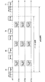
図11(A)に、第1TXOPリミット値内でTXOPを決定して、TXOP内でデータフレームを含む物理パケットの送信と送達確認応答フレーム(BAフレーム)の受信とを繰り返し行うシーケンス例を示す。図11(B)に、第1TXOPリミット値より低い第2TXOPリミット値内でTXOPを決定し、TXOP内でデータフレームを含む物理パケットの送信と送達確認応答フレーム(BAフレーム)の受信とを繰り返し行うシーケンス例を示す。図11(A)および図11(B)で破線の矩形は、基地局から受信するフレーム(ここではBAフレーム)であることを示す。 FIG. 11A shows an example of a sequence in which a TXOP is determined within the first TXOP limit value, and transmission of a physical packet including a data frame and reception of a delivery confirmation response frame (BA frame) are repeatedly performed within the TXOP. In FIG. 11B, a TXOP is determined within a second TXOP limit value lower than the first TXOP limit value, and transmission of a physical packet including a data frame and reception of a delivery acknowledgment frame (BA frame) are repeatedly performed in the TXOP. An example of a sequence is shown. 11A and 11B, a broken-line rectangle indicates a frame (here, a BA frame) received from the base station.
図11(A)の方が、長いTXOPを設定できるため、より多くのデータをSU送信できる。よって、トリガーフレームで指定されかつUL−MU送信に成功した端末(第2TXOPリミット値が適用される端末)と、それ以外の端末(第1TXOPリミット値が適用される端末)とで、無線媒体の使用に関してフェアネスの維持が可能となる。またUL−MU送信に成功した端末のSU送信はTXOPリミットが制限されているため、無線媒体の占有期間が少なくなり、基地局がトリガーフレームを送信可能な期間を確保しやすくなる。 Since a longer TXOP can be set in FIG. 11A, more data can be transmitted by SU. Therefore, the terminal (terminal to which the second TXOP limit value is applied) designated by the trigger frame and which has successfully transmitted the UL-MU and the other terminal (terminal to which the first TXOP limit value is applied) Fairness can be maintained for use. In addition, since the TX transmission limit of the terminal that succeeds in the UL-MU transmission is limited by the TXOP limit, the occupation period of the wireless medium is reduced, and it becomes easier to secure a period in which the base station can transmit the trigger frame.
上述したシーケンスでは、トリガーフレームで指定された端末は、UL−MU送信に失敗した場合も、タイマーの動作を維持して、タイマーがタイムアウトする前までは、第2TXOPリミット値を用いるようにした。UL−MU送信に失敗したものの、送信の機会を与えられたという点では、その他の端末に比べて優位であったといえるためである。別の方法として、トリガーフレームで指定された端末であっても、UL−MU送信に失敗した場合は、当該トリガーフレームによるタイマーの(再)起動をしないようにしてもよい。この場合は、送信が成功しなかったという点を重視した対応といえる。 In the above-described sequence, the terminal specified by the trigger frame maintains the operation of the timer even when the UL-MU transmission fails, and uses the second TXOP limit value until the timer times out. This is because although UL-MU transmission failed, transmission terminal was given an advantage over other terminals in that transmission opportunity was given. As another method, even if the terminal specified in the trigger frame fails in the UL-MU transmission, the timer may not be (re) started by the trigger frame. In this case, it can be said that the response emphasizes that the transmission was not successful.
上述したシーケンスでは、第1TXOPリミット値に基づき式1を計算して、第2TXOPリミット値を算出したが、予め第2TXOPリミット値をデータベースに格納しておいてもよい。この場合、端末は、当該データベースから、第2TXOPリミット値を読み出せばよい。第1TXOPリミットより段階的に小さくしたTXOPリミットの値を複数(第2TXOPリミット〜第mTXOPリミット。mは3以上の整数)データベースに格納してもよい。この場合、タイマーがタイムアウトする前まで期間において、キャリアセンスでSU送信用のアクセス権を獲得するごとに、段階的に低い値のTXOPリミット値を用いるようにしてもよい。
In the above-described sequence, the second TXOP limit value is calculated by calculating
上述したシーケンスでは、EDCAパラメータのうち、TXOPリミットのみを小さく変更したが、他のEDCAパラメータをTXOPリミットと共に変更してもよい。一例として、CWmin、CWmaxまたはこれらの両方を、大きくなるよう変更してもよい。または、AIFSNを、大きくなるよう変更してもよい。変更の方法は、TXOPリミットと同様の方法を用いればよい。例えば、一定の係数を乗じてもよいし、または、データベースに予め、候補となる1つ、または段階的に大きくした複数の値を格納しておく方法でもよい。AIFSNやCWmin、CWmaxを変更する場合、これらの値は次のSU送信のために予め用いられるものであるため、すでにバックオフカウンタのカウントダウンが開始されている状態でタイマーがタイムアウトした場合の挙動を考える必要がある。すでにバックオフカウンタのカウントダウンが開始されている状態でタイマーがタイムアウトした場合は、例えばそのままカウントダウンを継続してアクセス権の獲得を試み、新たにバックオフカウンタを取り直す際に変更されたAIFSNやCWmin、CWmax値を適用する。前述のTXOPリミットに関しても同様のタイミングで適用するようにしてもよい。あるいは、CWmin、CWmaxに関してはすでにカウントダウンされている現状値と新たに用いるパラメータから導出されたバックオフカウンタ初期値を比較し、新たに導出された初期値の方が小さければ現状のカウントダウン値を当該初期値で置き換えるようにしてもよい。 In the above-described sequence, only the TXOP limit among the EDCA parameters is changed to a small value, but other EDCA parameters may be changed together with the TXOP limit. As an example, CWmin, CWmax or both may be changed to be larger. Alternatively, the AIFSN may be changed to be larger. The change may be made using the same method as the TXOP limit. For example, a method of multiplying by a certain coefficient, or a method of storing one or a plurality of values that are gradually increased as candidates in a database in advance may be used. When changing AIFSN, CWmin, and CWmax, since these values are used in advance for the next SU transmission, the behavior when the timer times out in a state where the countdown of the back-off counter has already been started is described. You need to think. If the timer times out while the count-down of the back-off counter has already started, for example, the count-down is continued as it is, an attempt is made to acquire an access right, and the AIFSN or CWmin, Apply the CWmax value. The above-mentioned TXOP limit may be applied at the same timing. Alternatively, with respect to CWmin and CWmax, the current countdown value is compared with the current value that has already been counted down, and the initial value of the backoff counter derived from the newly used parameter is compared. If the newly derived initial value is smaller, the current countdown value is calculated. It may be replaced with an initial value.
図12は、本実施形態の第2の動作例に係る端末の動作のフローチャートである。 FIG. 12 is a flowchart of the operation of the terminal according to the second operation example of the present embodiment.
端末が、基地局からトリガーフレームを受信すると(S101)、トリガーフレームに基づき、自端末がUL−MU用に指定されているか判断する(S102)。自端末が指定されている場合は、トリガーフレームの受信完了から予め定めた時間後に、データフレームを含む物理パケットをUL−MU送信する(S103)。端末は、UL−MU送信後、基地局から送信される送達確認応答フレーム(M−BAフレーム等)を受信し、送達確認応答フレームを検査することで、UL−MU送信が成功したかを判断する(S104)。送信に失敗したデータが存在する場合は、次回以降の送信(UL−MU送信またはSU送信)の機会で再送信することを決定する。 When a terminal receives a trigger frame from a base station (S101), it determines whether the terminal is designated for UL-MU based on the trigger frame (S102). If the own terminal is designated, the physical packet including the data frame is transmitted by UL-MU after a predetermined time from the completion of receiving the trigger frame (S103). After transmitting the UL-MU, the terminal receives the acknowledgment response frame (M-BA frame or the like) transmitted from the base station and checks the acknowledgment response frame to determine whether the UL-MU transmission is successful. (S104). If there is data that failed to be transmitted, it is determined that the data should be retransmitted at the next transmission (UL-MU transmission or SU transmission).
端末は、UL−MU送信後もUL送信したいデータが存在する場合、SU送信用のアクセス権を獲得するため、AIFS[AC]とランダムに決定したバックオフ時間との合計である待機時間の間、キャリアセンスを行う。端末は、キャリアセンスの間、キャリア検知がなければ、無線媒体へのアクセス権を獲得する。端末は、アクセス権を獲得できた場合は、該当するACの送信バッファからデータを読み出してデータフレームを生成する。この際、使用するTXOPリミット値を決定し、当該TXOPリミット値以下の範囲内でTXOPを決定する。具体的に、変更条件が満たされるかを判断し(S106)、変更条件が満たされない場合は、第1TXOPリミット値を用いることを決定し、第1TXOPリミット値以下の範囲で、TXOPを決定する(S109)。一方、変更条件が満たされる場合は、第1TXOPリミット値より小さい第2TXOPリミット値以下の範囲で、TXOPを決定する(S107)。一例として、第1TXOPリミット値は、予めシステムで定められたデフォルト値(図7参照)、または基地局がBSS内で事前に設定した値である。 If there is data to be transmitted in the UL even after the UL-MU transmission, the terminal obtains an access right for the SU transmission during a standby time that is a sum of AIFS [AC] and a randomly determined back-off time. Perform carrier sense. The terminal acquires the right to access the wireless medium during the carrier sense if there is no carrier detection. If the terminal can acquire the access right, the terminal reads data from the transmission buffer of the corresponding AC and generates a data frame. At this time, the TXOP limit value to be used is determined, and the TXOP is determined within a range equal to or less than the TXOP limit value. Specifically, it is determined whether or not the change condition is satisfied (S106). If the change condition is not satisfied, it is determined to use the first TXOP limit value, and the TXOP is determined within a range equal to or less than the first TXOP limit value ( S109). On the other hand, when the change condition is satisfied, the TXOP is determined in a range that is smaller than the first TXOP limit value and equal to or less than the second TXOP limit value (S107). As an example, the first TXOP limit value is a default value predetermined by the system (see FIG. 7) or a value preset by the base station in the BSS.
端末は、決定したTXOPに応じた値を、送信するデータフレームのMACヘッダのDuration/IDフィールドに設定する。そして、データフレームを含む物理パケットをSU送信する(S108)。この後、次のトリガーフレームを受信しておらず(S110のNO)、かつ送信したいデータが存在する場合は、ステップS105に戻る。前述したように、SU用のアクセス権を獲得するごとに、TXOPリミット値をさらに段階的に下げていってもよい。基地局から、次のトリガーフレームを受信した場合は(S110のYES)、ステップS102に戻る。 The terminal sets a value corresponding to the determined TXOP in the Duration / ID field of the MAC header of the data frame to be transmitted. Then, the physical packet including the data frame is transmitted by SU (S108). Thereafter, if the next trigger frame has not been received (NO in S110) and there is data to be transmitted, the process returns to step S105. As described above, each time the SU access right is acquired, the TXOP limit value may be further reduced in a stepwise manner. If the next trigger frame has been received from the base station (YES in S110), the process returns to step S102.
ここで、変更条件の例を詳細に説明する。前述した第2のシーケンス例のように、第1の変更条件としては、トリガーフレームで自端末が指定されかつUL−MU送信に成功した場合に、トリガーフレームの受信完了(または送信開始)から一定時間内に含まれるか否かがある。一定時間に含まれる場合は、変更条件が満たされ、含まれない場合は、変更条件が満たされない。一定時間の長さは、例えばトリガーフレームが一定周期で送信される場合に、当該一定周期の長さでもよい。あるいは、これより短くしても長くしてもよい。 Here, an example of the change condition will be described in detail. As in the above-described second sequence example, the first change condition is that, when the own terminal is specified in the trigger frame and the UL-MU transmission succeeds, the constant from the completion of reception of the trigger frame (or the start of transmission) It may or may not be included in time. If it is included in the fixed time, the change condition is satisfied; otherwise, the change condition is not satisfied. The length of the fixed time may be, for example, when the trigger frame is transmitted in a fixed cycle, the length of the fixed cycle. Alternatively, it may be shorter or longer.
具体的な実装例としては、前述したように、トリガーフレームの受信完了時に、当該一定時間の長さ(例えばトリガーフレームの周期長)を設定したタイマーを起動し、タイマーがタイムアウトしない間は、変更条件が満たされると判断する。タイマーが起動していないまたはタイムアウトした場合は、変更条件が満たされないと判断する。この場合、少なくとも次のトリガーフレームの受信までは、変更条件は満たされないと判断され続ける。 As a specific implementation example, as described above, when the reception of the trigger frame is completed, the timer that sets the length of the fixed time (for example, the cycle length of the trigger frame) is started, and the change is performed while the timer does not time out. It is determined that the condition is satisfied. If the timer has not started or has timed out, it is determined that the change condition is not satisfied. In this case, it is determined that the change condition is not satisfied at least until the next trigger frame is received.
タイマーを動作させる起点は、トリガーフレームの受信完了時点に限定されない。トリガーフレームの受信完了より後、例えばM−BAフレームの受信で自装置の送信が成功したことを確認した時点で、タイマーを設定してもよい。この場合、タイマーに設定する値は、次のトリガーフレームの受信までの残り時間などでもよい。どの時点でタイマーを設定するかに応じて、タイマーに設定する値は、適宜調整すればよい。 The starting point of the operation of the timer is not limited to the completion of receiving the trigger frame. After completion of the reception of the trigger frame, the timer may be set, for example, when it is confirmed that the transmission of the own apparatus has been successful in the reception of the M-BA frame. In this case, the value set in the timer may be the remaining time until the next trigger frame is received. The value to be set in the timer may be adjusted as appropriate depending on when the timer is set.
ここでタイマーに設定する値(以下、タイマー設定値)を決定する例を示す。タイマー設定値は、端末で決定する方法と、基地局で決定する方法がある。 Here, an example of determining a value to be set in the timer (hereinafter, a timer setting value) will be described. The timer setting value may be determined by the terminal or by the base station.
端末でタイマー設定値を決定する場合、例えばトリガーフレームの送信周期を観測し、トリガーフレームの送信周期の整数倍にタイマー設定値を決定する。送信周期の整数倍から、トリガーフレームのパケット長(PPDU長)を引いた値を、タイマー設定値に決定してもよい。端末が持っているトラヒック(送信バッファのデータ量等)に応じて、送信周期に乗じる整数を決定してもよい。例えばAC_VOの送信バッファに蓄積されているデータ量が多いほど、整数の値を小さく、あるいは、当該データ量が少ないほど、整数の値を大きくしてもよい。あるいは、これとは逆の関係に設定してもよい。 When the terminal determines the timer setting value, for example, the transmission period of the trigger frame is observed, and the timer setting value is determined to be an integral multiple of the transmission period of the trigger frame. A value obtained by subtracting the packet length (PPDU length) of the trigger frame from the integral multiple of the transmission cycle may be determined as the timer setting value. An integer by which the transmission cycle is multiplied may be determined according to the traffic (such as the amount of data in the transmission buffer) possessed by the terminal. For example, the larger the data amount stored in the AC_VO transmission buffer, the smaller the integer value may be, or the smaller the data amount, the larger the integer value may be. Alternatively, the relationship may be set in the opposite manner.
または、基地局がトリガーフレームの送信周期を予めBSS内の複数の端末に通知し、各端末が、当該自端末のトラヒック(データ量)と、通知された送信周期とから、タイマー設定値を決めてもよい。例えば送信周期に応じた閾値を設定し、トラヒックが閾値以下であれば、タイマー設定値を大きな値、閾値より大きければ、タイマー設定値を小さな値に設定する。あるいは、これとは逆の関係に設定してもよい。送信周期が長いほど、閾値を大きな値に設定してもよい。 Alternatively, the base station notifies a plurality of terminals in the BSS in advance of the trigger frame transmission cycle, and each terminal determines a timer setting value from the traffic (data amount) of the own terminal and the notified transmission cycle. You may. For example, a threshold value according to the transmission cycle is set, and if the traffic is equal to or less than the threshold value, the timer setting value is set to a large value. Alternatively, the relationship may be set in the opposite manner. The threshold may be set to a larger value as the transmission cycle is longer.
基地局でタイマー設定値を決定する場合、例えば、当該基地局がBSSに属する端末からバッファステータスレポート(Buffer Status Report:BSR)を受信し、BSRを用いて、タイマー設定値を決定する。BSRは、例えばACごとのトラフィックの情報を含む。BSRは、QoS ControlフィールドまたはHE Controlフィールドに入れられてもよいし、管理フレームの情報エレメントとして送信されてもよい。BSRは、端末によって自発的に送信されてもよいし、基地局から端末にBSRの送信要求を送り、当該要求に応じて端末がBSRを送信してもよい。当該送信要求がトリガーフレームに含まれていても良い。 When the base station determines a timer setting value, for example, the base station receives a buffer status report (BSR) from a terminal belonging to the BSS, and determines the timer setting value using the BSR. The BSR includes, for example, traffic information for each AC. The BSR may be put in a QoS Control field or an HE Control field, or may be transmitted as an information element of a management frame. The BSR may be transmitted spontaneously by the terminal, or the base station may transmit a BSR transmission request to the terminal, and the terminal may transmit the BSR in response to the request. The transmission request may be included in the trigger frame.
基地局は、端末ごとにタイマー設定値を決定してもよい。例えば、端末が持っているトラヒックが多いほど、タイマー設定値を小さく、あるいは、少ないほどタイマー設定値を大きくする。あるいは、これとは逆の関係に設定してもよい。また、基地局は、複数の端末に共通にタイマー設定値を決定してもよい。この場合は、複数の端末のトラヒック(データ量)を、統計処理(例えば平均)して、タイマー設定値を決めればよい。タイマー設定値はACごとに決定してもよい。基地局は、端末ごと、または端末に共通に決定したタイマー設定値を、各端末に通知する。通知には、トリガーフレームを利用してもよいし、ビーコンフレーム等の管理フレームを利用してもよいし、その他のフレームを利用してもよい。 The base station may determine the timer setting value for each terminal. For example, the timer setting value decreases as the terminal has more traffic, or the timer setting value increases as the terminal has less traffic. Alternatively, the relationship may be set in the opposite manner. Further, the base station may determine the timer setting value commonly for a plurality of terminals. In this case, the traffic (data amount) of the plurality of terminals may be statistically processed (for example, averaged) to determine the timer setting value. The timer setting value may be determined for each AC. The base station notifies each terminal of a timer setting value determined for each terminal or commonly for each terminal. For the notification, a trigger frame may be used, a management frame such as a beacon frame may be used, or another frame may be used.
変更条件の第2の例としては、トリガーフレームで自端末が指定されかつUL−MU送信に成功した場合に、その後、所定のフレームを受信したかがある。所定のフレームとして、ビーコンフレームでもよい。ビーコンフレームを受信する前までは、変更条件が満たされると判断し、ビーコンフレームを受信した場合は、変更条件が満たさなくなったと判断する。この後、次のトリガーフレームで自端末が指定されかつUL−MU送信に成功した場合に、再度、変更条件が満たされると判断される。トリガーフレームの周期は、ビーコンフレームの周期より短いことを想定するが、長くてもよい。ここでは所定のフレームとしてビーコンフレームの場合を記述したが、別のフレームでもよい。所定のフレームを受信するタイミングが事前に分かっている場合は、前述したタイマーを利用した方法でも同様の動作を実現可能である。受信したフレームの種別は、例えばMACヘッダのフレームコントロールフィールドのタイプおよびサブタイプを解析することで判断してもよい。 As a second example of the change condition, when the terminal itself is specified in the trigger frame and the UL-MU transmission is successful, a predetermined frame is received thereafter. The predetermined frame may be a beacon frame. Until a beacon frame is received, it is determined that the change condition is satisfied. If a beacon frame is received, it is determined that the change condition is not satisfied. Thereafter, when the own terminal is specified in the next trigger frame and the UL-MU transmission succeeds, it is determined that the change condition is satisfied again. The period of the trigger frame is assumed to be shorter than the period of the beacon frame, but may be longer. Here, the case of a beacon frame is described as the predetermined frame, but another frame may be used. If the timing of receiving the predetermined frame is known in advance, the same operation can be realized by the above-described method using the timer. The type of the received frame may be determined, for example, by analyzing the type and subtype of the frame control field of the MAC header.
変更条件の第3の例として、トリガーフレームの受信回数と、トリガーフレームに応答してフレームの送信(UL−MU送信)に成功した回数に基づいて、変更条件の成否を判断してもよい。例えば、トリガーフレームの受信回数に対するフレーム送信の成功回数の比が、閾値以上の場合に変更条件が満たされ、当該比が閾値未満の場合、変更条件が満たされないと判断してもよい。一例として、変更条件が満たされる場合は、第2TXOPリミット値、満たされない場合は第1TXOPリミット値を用いる。このように、トリガーフレームの受信回数とフレーム送信の成功回数に基づいて、使用するTXOPリミット値を制御する。 As a third example of the change condition, the success or failure of the change condition may be determined based on the number of times the trigger frame has been received and the number of times the frame transmission (UL-MU transmission) has succeeded in response to the trigger frame. For example, it may be determined that the change condition is satisfied when the ratio of the number of successful frame transmissions to the number of trigger frame receptions is equal to or greater than the threshold, and that the change condition is not satisfied when the ratio is less than the threshold. As an example, if the change condition is satisfied, the second TXOP limit value is used, and if not, the first TXOP limit value is used. Thus, the TXOP limit value to be used is controlled based on the number of times the trigger frame has been received and the number of times the frame has been successfully transmitted.
変更条件の第4の例として、トリガーフレームに応答してフレームの送信(UL−MU送信)に成功した回数と、シングルユーザ送信でフレームの送信に成功した回数とに基づいて、変更条件の成否を判断してもよい。例えばシングルユーザ送信の成功回数に対するUL−MU送信の成功回数の比が閾値以上の場合に変更条件が満たされ、当該比が閾値未満の場合、変更条件が満たされないと判断してもよい。一例として、変更条件が満たされる場合は、第2TXOPリミット値、満たされない場合は第1TXOPリミット値を用いる。このように、シングルユーザ送信の成功回数とUL−MU送信の成功回数に基づいて、使用するTXOPリミット値を制御する。つまり、この場合、UL−MU送信の履歴に加えて、SU送信の履歴を用いて、TXOPリミットの値を変更するよう制御する。SU送信の履歴は、SU送信の実行有無、SU送信の実行回数、およびSU送信の成功または失敗の実行結果、SU送信(例えば基準となるSU送信、所定の時点で行ったSU送信など)からの経過時間のうちの少なくとも1つを含む。 As a fourth example of the change condition, the success / failure of the change condition is determined based on the number of successful frame transmissions (UL-MU transmission) in response to the trigger frame and the number of successful frame transmissions in single-user transmission. May be determined. For example, if the ratio of the number of successful UL-MU transmissions to the number of successful single-user transmissions is equal to or greater than a threshold, the change condition may be satisfied. If the ratio is less than the threshold, it may be determined that the change condition is not satisfied. As an example, if the change condition is satisfied, the second TXOP limit value is used, and if not, the first TXOP limit value is used. In this way, the TXOP limit value to be used is controlled based on the number of successful single-user transmissions and the number of successful UL-MU transmissions. That is, in this case, control is performed to change the value of the TXOP limit using the history of SU transmission in addition to the history of UL-MU transmission. The history of SU transmission is based on whether or not SU transmission has been performed, the number of times SU transmission has been performed, the result of successful or unsuccessful SU transmission, and SU transmission (for example, reference SU transmission, SU transmission performed at a predetermined time, etc.). At least one of the elapsed times.
上述した変更条件の第3および第4の例において、トリガーフレームに応答してフレームの送信(UL−MU送信)に成功した回数の代わりに、トリガーフレームに応答してフレームを送信した回数(自装置が指定された回数)を用いてもよい。 In the third and fourth examples of the change conditions described above, instead of the number of successful transmissions of the frame (UL-MU transmission) in response to the trigger frame, the number of transmissions of the frame in response to the trigger frame (the (The number of times the device is designated).
上述した第1の変更条件の例では、タイマーがタイムアウトするまでは変更条件が満たされるとして第2TXOPリミット値が用いたが、経過時間に応じて、第2TXOPリミット値を段階的に変更してもよい。例えばタイムアウトが近づくほど、第2TXOPリミット値が、第1TXOPリミット値に近づくように大きくしてもよい。 In the above-described example of the first change condition, the second TXOP limit value is used assuming that the change condition is satisfied until the timer times out. However, the second TXOP limit value may be changed stepwise according to the elapsed time. Good. For example, as the timeout approaches, the second TXOP limit value may be increased so as to approach the first TXOP limit value.
また、上述した第3の変更条件の例では、トリガーフレームの受信回数に対するフレーム送信の成功回数の比が閾値以上の場合に、変更条件が満たされるとして、第2TXOPリミット値を用いた。別の方法として、当該比が大きくなるほど、第1TXOPリミット値との差が大きくなるように、TXOPリミット値を変更(TXOPリミット値を小さく)してもよい。あるいは、当該比が小さくなるほど、第1TXOPリミット値との差が小さくなるように、TXOPリミット値を制御(TXOPリミット値を大きく)してもよい。 Further, in the above-described example of the third change condition, the second TXOP limit value is used assuming that the change condition is satisfied when the ratio of the number of successful frame transmissions to the number of trigger frame receptions is equal to or greater than the threshold. As another method, the TXOP limit value may be changed (the TXOP limit value is reduced) so that the difference from the first TXOP limit value increases as the ratio increases. Alternatively, the TXOP limit value may be controlled (the TXOP limit value is increased) such that the difference from the first TXOP limit value decreases as the ratio decreases.
また、第4の変更条件の例では、シングルユーザ送信の成功回数に対するUL−MU送信の成功回数の比が閾値以上の場合に、変更条件が満たされるとして、第2TXOPリミット値を用いた。別の方法として、当該比が大きくなるほど、第1TXOPリミット値との差が大きくなるように、TXOPリミット値を変更(TXOPリミット値を小さく)してもよい。あるいは、当該比が小さくなるほど、第1TXOPリミット値との差が小さくなるように、TXOPリミット値を制御(TXOPリミット値を大きく)してもよい。 In the example of the fourth change condition, the second TXOP limit value is used assuming that the change condition is satisfied when the ratio of the number of successful UL-MU transmissions to the number of successful single-user transmissions is equal to or greater than a threshold. As another method, the TXOP limit value may be changed (the TXOP limit value is reduced) so that the difference from the first TXOP limit value increases as the ratio increases. Alternatively, the TXOP limit value may be controlled (the TXOP limit value is increased) such that the difference from the first TXOP limit value decreases as the ratio decreases.
上述した第2の動作例では端末側の動作によりTXOPリミット値の変更を行ったが、基地局側で、各端末のUL−MU送信の履歴に基づき、各端末で使用するTXOPリミット値を決定し、決定したTXOPリミット値を、各端末に通知してもよい。通知には、トリガーフレーム、またはビーコンフレーム等のその他のフレームを用いることができる。基地局で各端末が使用するTXOPリミット値を決定する方法は、上述した端末が決定する場合と同様のアルゴリズムを用いればよい。複数の端末のうち少なくとも1つの端末のみ基地局が、使用するTXOPリミット値を決定し、残りの端末は自端末で、使用するTXOPリミット値を決定することも可能である。この場合、基地局は、当該少なくとも1つの端末のみ、通知を行えばよい。 In the second operation example described above, the TXOP limit value is changed by the operation of the terminal, but the base station determines the TXOP limit value to be used by each terminal based on the UL-MU transmission history of each terminal. Then, the determined TXOP limit value may be notified to each terminal. The notification may use a trigger frame or another frame such as a beacon frame. A method of determining the TXOP limit value used by each terminal in the base station may use the same algorithm as that used by the terminal described above. It is also possible for the base station to determine the TXOP limit value to be used by at least one terminal among the plurality of terminals, and to determine the TXOP limit value to be used by the remaining terminals. In this case, the base station only needs to notify the at least one terminal.
上述した第1〜第4の変更条件のうち使用する変更条件は、予め端末に記憶されていてもよいし、基地局が、当該変更条件を特定する情報を、各端末に通知してもよい。通知には、一例として、トリガーフレーム、またはビーコンフレーム等の他のフレームを用いることができる。 The change condition to be used among the first to fourth change conditions described above may be stored in the terminal in advance, or the base station may notify each terminal of information specifying the change condition. . For example, a trigger frame or another frame such as a beacon frame can be used for the notification.
以上のように第2の動作例では、UL−MU送信したデータと同一のACに属するデータについて、TXOPリミット値を小さく変更したが、他のACについても、TXOPリミット値を変更してもよい。ただし、TXOPリミット値の下限値は0であるとし、TXOPリミットのデフォルト値が0である場合は、これ以上小さくしない。小さくしてもよいが、この場合は、TXOPリミット値が0であるとみなして、TXOPを決定するものとする。 As described above, in the second operation example, the TXOP limit value is changed to be smaller for data belonging to the same AC as the data transmitted by the UL-MU, but the TXOP limit value may be changed for other ACs. . However, it is assumed that the lower limit of the TXOP limit value is 0, and when the default value of the TXOP limit is 0, the lower limit is not further reduced. Although the value may be reduced, in this case, the TXOP limit value is regarded as 0 and the TXOP is determined.
例えば、図12のステップS103でUL−MU送信したデータが属するAC(仮にAC−1と記載)と、その後のステップS108のSUで送信しようとするデータが属するAC(仮にAC−2と記載)が異なる場合を考える。この場合も、図12の動作フローに従って、AC−2に属するデータのSU送信用に、ステップS107でTXOPリミット値の変更を行ってもよい。あるいは、AC−1とAC−2が異なる場合、図12の動作フローの適用外とし、TXOPリミット値の変更を行わない(通常のTXOPリミット値を使う)ようにしてもよい。 For example, the AC to which the data transmitted in UL-MU in step S103 of FIG. 12 belongs (temporarily described as AC-1), and the AC to which the data to be transmitted in the SU in step S108 thereafter belongs (temporarily described as AC-2) Are different. Also in this case, the TXOP limit value may be changed in step S107 for SU transmission of data belonging to AC-2 according to the operation flow of FIG. Alternatively, when AC-1 and AC-2 are different, the operation flow of FIG. 12 may not be applied, and the TXOP limit value may not be changed (a normal TXOP limit value is used).
また、上述した第2の動作例では、UL−MU送信するデータのACを端末側で決定する場合を想定したが、第1の動作例と同様に、基地局がトリガーフレームでACを推奨または指定してもよい。トリガーフレームでACが推奨または指定されたいた場合の動作は、第1の動作例と同様でよい。 Further, in the above-described second operation example, it is assumed that the terminal determines the AC of the data to be transmitted by the UL-MU. However, as in the first operation example, the base station recommends the AC in the trigger frame or May be specified. The operation when the AC is recommended or specified in the trigger frame may be similar to the first operation example.
また、上述し第2の動作例において、第1の動作例と同様に、基地局は、トリガーフレームとして、ランダムアクセス用トリガーフレーム(TF−R)を送信してもよい。この場合、図12のフローチャートにおいて、トリガーフレームで自端末が指定されたかの判断(図12のS102)を、端末側でランダムアクセスするかの判断に置き換えればよい。そして、ランダムアクセスを行うことを決定した場合は、図12のステップS103に進むようにすればよい。 Further, in the above-described second operation example, similarly to the first operation example, the base station may transmit a random access trigger frame (TF-R) as a trigger frame. In this case, in the flowchart of FIG. 12, the determination as to whether or not the terminal itself is specified in the trigger frame (S102 in FIG. 12) may be replaced with the determination as to whether or not the terminal performs random access. When it is determined that random access is to be performed, the process may proceed to step S103 in FIG.
なお、上述した第2の動作例において、決定したTXOPから送信パケット長を引いた値を、MACヘッダのDuration/IDフィールドに無線媒体の予約時間として設定したが、物理ヘッダに同様のフィールドが存在する場合は、物理ヘッダに当該予約時間を設定してもよい。また、決定したTXOPの値を格納するフィールドが物理ヘッダまたはMACヘッダ内に存在する場合は、当該TXOPの値を当該フィールドに格納してもよい。 In the second operation example described above, the value obtained by subtracting the transmission packet length from the determined TXOP is set as the reservation time of the wireless medium in the Duration / ID field of the MAC header, but a similar field exists in the physical header. In this case, the reservation time may be set in the physical header. When a field for storing the determined TXOP value exists in the physical header or the MAC header, the value of the TXOP may be stored in the field.
(本実施形態の第3の動作例)
端末で、UL−MU能力の有効(Able)および無効(Disable)を切り替え可能である場合を想定する。端末は、UL−MU能力の有効または無効の設定状態に応じて、TXOPリミット値を変更してもよい。例えば端末内部でアンテナを共用する他システム(LTE(Long Term Evolution)、Bluetooth(登録商標)など)が存在する場合を考える。無線LAN回路と、他システムとの間で電波干渉問題がある場合、端末内でUL−MU能力を無効にして、この干渉問題を緩和することが考えられる。UL−MUが可能な環境では、基地局からのトリガーフレームに応じてUL−MU送信する場合に、トリガーフレームで指定された条件で送信を行う必要がある(例えば基地局が指定した送信電力で送信する必要がある)ため、このことが他システムとの干渉を引き起こす可能性がある。そこで、端末はUL−MU能力を無効にして、SUモードに移行することが考えられる。
(Third operation example of the present embodiment)
It is assumed that the terminal is capable of switching between valid (able) and invalid (disable) UL-MU capabilities. The terminal may change the TXOP limit value according to the setting state of the validity or invalidity of the UL-MU capability. For example, consider a case where there is another system (LTE (Long Term Evolution), Bluetooth (registered trademark), or the like) that shares an antenna inside the terminal. When there is a radio interference problem between the wireless LAN circuit and another system, it is conceivable to mitigate this interference problem by disabling the UL-MU capability in the terminal. In an environment where UL-MU is possible, when UL-MU transmission is performed in response to a trigger frame from the base station, it is necessary to perform transmission under the conditions specified by the trigger frame (for example, with the transmission power specified by the base station). Transmission), which can cause interference with other systems. Therefore, it is conceivable that the terminal invalidates the UL-MU capability and shifts to the SU mode.
端末は、UL−MU能力が無効のときは、図7に示す通常のTXOPリミット値(第1TXOPリミット値)を用いる。UL−MU能力が有効のときは、優先度を低めた(値を小さくした)TXOPリミット値を用いる。TXOPリミット値の変更は、TXOPリミットのデフォルト値が0より大きいAC−VOとAC−VIのみを対象としてもよい。この変更後のTXOPリミット値は、予め定められていてもよいし、基地局が決定して、端末に通知してもよい。基地局からの通知は、ビーコンフレームやアソシエーション応答フレーム等の管理フレームを用いてもよいし、他の種類のフレームを用いてもよい。また前述の他の動作例、例えばタイマーに基づく動作とUL−MU能力の有効・無効設定を連動させるようにしてもよい。タイマーが起動しており、変更条件が満たされるとしている場合にはUL−MU能力を有効と設定、タイマーが起動しておらず(タイムアウトした場合も含む)、変更条件が満たされないとする場合にはUL−MU能力を無効と設定するというような連動である。 When the UL-MU capability is invalid, the terminal uses the normal TXOP limit value (first TXOP limit value) shown in FIG. When the UL-MU capability is valid, a TXOP limit value with a lower priority (a smaller value) is used. The change of the TXOP limit value may be applied only to AC-VO and AC-VI in which the default value of the TXOP limit is larger than 0. The changed TXOP limit value may be determined in advance, or may be determined by the base station and notified to the terminal. The notification from the base station may use a management frame such as a beacon frame or an association response frame, or may use another type of frame. Further, another operation example described above, for example, the operation based on the timer and the valid / invalid setting of the UL-MU capability may be linked. If the timer is activated and the change condition is satisfied, the UL-MU capability is set to be valid. If the timer is not activated (including the case of timeout) and the change condition is not satisfied, Are linked such that the UL-MU capability is set to invalid.
ここでは、EDCAパラメータとしてTXOPリミットを対象に述べたが、CWmin、CWmaxまたはAIFSNなど、他のEDCAパラメータの値を、同様にして制御してもよい。例えば、UL−MU能力が無効のときは、図7に示す通常のパラメータ値を用い、UL−MU能力が有効のときは、優先度を低めた(値を大きくした)パラメータ値を用いる。あるいは、UL−MU能力が無効のときは、図7に示す通常のパラメータ値よりも低いパラメータ値を用い、UL−MU能力が有効のときは、図7に示す通常のパラメータ値を用いてもよい。ここで述べた以外の方法を用いてもよい。TXOPリミット、CWmin、CWmaxまたはAIFSNの任意の組み合わせの値を、同様にして制御してもよい。 Here, the TXOP limit has been described as the EDCA parameter, but the value of another EDCA parameter such as CWmin, CWmax, or AIFSN may be controlled in a similar manner. For example, when the UL-MU capability is invalid, a normal parameter value shown in FIG. 7 is used, and when the UL-MU capability is valid, a parameter value with a lower priority (increased value) is used. Alternatively, when the UL-MU capability is invalid, a parameter value lower than the normal parameter value shown in FIG. 7 is used, and when the UL-MU capability is valid, the normal parameter value shown in FIG. 7 is used. Good. Methods other than those described here may be used. The value of any combination of TXOP limit, CWmin, CWmax or AIFSN may be controlled in a similar manner.
端末は、UL−MU能力の有効または無効を表す情報を、基地局に通知する。通知は、例えばHE Controlフィールドに無効フィールドを設け、当該フィールドにビットを立てることで、行ってもよい。あるいは、通知は、既存のフィールドの予約領域を使って行ってもよいし、任意の管理フレームで情報エレメントとして有効または無効の情報を通知する方法でもよい。無効の通知を受けた基地局は、当該端末は、UL−MU送信を実行できない端末として認識し、UL−MUのスケジューリングの対象から除外するなどの処理を行う。 The terminal notifies the base station of information indicating whether the UL-MU capability is valid or invalid. The notification may be performed, for example, by providing an invalid field in the HE Control field and setting a bit in the invalid field. Alternatively, the notification may be performed using a reserved area of an existing field, or a method of notifying valid or invalid information as an information element in an arbitrary management frame. The base station that has received the invalid notification recognizes the terminal as a terminal that cannot execute UL-MU transmission, and performs processing such as excluding the terminal from UL-MU scheduling.
図13は、本実施形態の第3の動作例に係る端末の動作のフローチャートである。端末は、任意のタイミングで、UL−MU能力の有効または無効を決定する(S121)。例えば、端末内でアンテナを共用する他システムとの干渉を測定し、測定値が一定値以上であれば、無効を決定する。または、予め定めた他システムが動作中の場合は、常に無効を決定するなど、別の判断方法を用いてもよい。端末は、有効または無効を決定した場合は、有効または無効を表す情報を、基地局に通知する(S122)。端末は、UL−MU能力の無効を決定した場合は、SUモードに移行し、TXOPリミット値として、通常のTXOPリミット値(第1TXOPリミット値)を用いることを決定する。一方、UL−MU能力が有効の場合は、第1TXOPリミット値より低い第2TXOPリミット値を用いることを決定する(S124)。 FIG. 13 is a flowchart of the operation of the terminal according to the third operation example of the present embodiment. The terminal determines whether the UL-MU capability is valid or invalid at an arbitrary timing (S121). For example, the terminal measures the interference with another system sharing the antenna, and if the measured value is a certain value or more, invalidity is determined. Alternatively, when another predetermined system is operating, another determination method may be used, such as always determining invalidity. If the terminal determines valid or invalid, the terminal notifies the base station of information indicating valid or invalid (S122). When the terminal determines that the UL-MU capability is invalid, the terminal shifts to the SU mode, and determines to use a normal TXOP limit value (first TXOP limit value) as the TXOP limit value. On the other hand, if the UL-MU capability is valid, it is determined to use the second TXOP limit value lower than the first TXOP limit value (S124).
上述した説明では、端末側でTXOPリミット値の変更を制御したが、端末のUL−MU能力の有効または無効の設定状態に基づき、基地局側で、当該端末が使用するTXOPリミット値を決定してもよい。この場合、基地局は、決定したTXOPリミット値を端末に通知する。複数の端末のうち少なくとも1つの端末のみ基地局で、当該端末が使用するTXOPリミット値を決定し、残りの端末は自端末で、使用するTXOPリミット値を決定することも可能である。この場合、基地局は、当該少なくとも1つの端末のみ、通知を行えばよい。 In the above description, the terminal controls the change of the TXOP limit value. However, the base station determines the TXOP limit value used by the terminal based on the setting state of the UL-MU capability of the terminal. You may. In this case, the base station notifies the terminal of the determined TXOP limit value. It is also possible that the base station determines the TXOP limit value used by at least one terminal among the plurality of terminals, and the remaining terminals determine the TXOP limit value used by the own terminal. In this case, the base station only needs to notify the at least one terminal.
(本実施形態の第4の動作例)
基地局によるトリガーフレームの送信について説明する。以下の説明は、トリガーフレームがTF−Rの場合も適用可能である。
(Fourth operation example of the present embodiment)
The transmission of the trigger frame by the base station will be described. The following description is also applicable when the trigger frame is TF-R.
基地局は、一例として、トリガーフレームを周期的に送信する。基地局は、トリガーフレームの送信前にキャリアセンスを行う。前述したように、固定時間(AIFS等)とランダムに決めたバックオフ時間との間、キャリアセンスを行い、キャリアが検知されなければ、アクセス権を獲得し、トリガーフレームを送信する。この場合のトリガーフレームの送信シーケンス例を図14(A)に示す。トリガーフレーム51A、51B、51Cを所定の周期で送信している。送信前に、AIFSとバックオフ時間との間、キャリアセンスを行っている。 The base station periodically transmits a trigger frame, for example. The base station performs carrier sense before transmitting the trigger frame. As described above, carrier sense is performed between a fixed time (AIFS or the like) and a randomly determined back-off time, and if no carrier is detected, an access right is acquired and a trigger frame is transmitted. FIG. 14A shows an example of a trigger frame transmission sequence in this case. The trigger frames 51A, 51B, 51C are transmitted at a predetermined cycle. Before transmission, carrier sensing is performed between the AIFS and the backoff time.
または、キャリアセンスの別の方法として、ビーコンフレームと同様に送信前にPIFSの間キャリアセンスを行い、キャリアが検知されなければ、アクセス権を獲得し、トリガーフレームを送信してもよい。この場合のトリガーフレームの送信シーケンスの例を図14(B)に示す。送信前に、PIFSの間、キャリアセンスを行っている。これは、ビーコンフレームの送信の場合と同様の動作である。これにより、トリガーフレームを、管理フレームであるビーコンフレームのように送信できる。なお、PIFSの代わりに、別の固定時間を用いてもよい。 Alternatively, as another method of carrier sensing, carrier sensing may be performed during PIFS before transmission as in the case of a beacon frame, and if no carrier is detected, an access right may be acquired and a trigger frame may be transmitted. FIG. 14B shows an example of a trigger frame transmission sequence in this case. Before transmission, carrier sensing is performed during PIFS. This is the same operation as the case of transmitting a beacon frame. Thereby, a trigger frame can be transmitted like a beacon frame which is a management frame. Note that another fixed time may be used instead of PIFS.
基地局は、キャリアセンスでキャリアが検知された場合(ビジーの場合)、アクセス権を獲得できず、送信周期のタイミングでトリガーフレームを送信できない。この場合、基地局は、再度キャリアセンスを行い、アイドル状態を示すキャリアセンス結果が得られるまで、キャリアセンスを繰り返し行ってもよい。これにより、トリガーフレームの送信タイミングが遅れることとなる。この場合のシーケンス例を図15(A)に示す。トリガーフレーム51Aの送信が、送信周期のタイミングより遅れて送信されている。この動作は、ビーコンフレームの送信のためのキャリアセンスでビジーとなった場合と同様である。つまり、ビーコンフレームの送信では、キャリアセンスビジーとしてアクセス権を獲得できなかったときは、獲得できるまで、キャリアセンスを繰り返す。
When the carrier is detected by the carrier sense (in the case of busy), the base station cannot acquire the access right and cannot transmit the trigger frame at the timing of the transmission cycle. In this case, the base station may perform the carrier sense again and repeat the carrier sense until a carrier sense result indicating the idle state is obtained. As a result, the transmission timing of the trigger frame is delayed. FIG. 15A shows a sequence example in this case. The transmission of the
基地局は、繰り返しキャリアセンスを行う間に、一定の条件が満たされた場合は、トリガーフレームの送信を中止(断念)し、次回の送信タイミングまで待ってもよい。一定の条件として、例えば次の送信タイミングまでの残り時間が一定値以下になった場合は、今回のトリガーフレームの送信を中止することを決定してもよい。または、送信周期のタイミングから閾値時間を越えた場合は、今回のトリガーフレームの送信を中止することを決定してもよい。閾値時間は、送信周期の長さに応じて決定してもよい。例えば、閾値時間は、送信周期の長さの2分の1でもよい。この場合のシーケンス例を図15(B)に示す。キャリアセンスのビジーが続いたため、トリガーフレーム51Aの送信が、送信周期のタイミングから、送信周期長の2分の1経過しても送信できない。このため、トリガーフレーム51Aの送信を中止する。
If certain conditions are satisfied during repeated carrier sensing, the base station may stop (abandon) the transmission of the trigger frame and wait until the next transmission timing. As a certain condition, for example, when the remaining time until the next transmission timing becomes equal to or less than a certain value, it may be determined to stop the transmission of the current trigger frame. Alternatively, if the threshold time is exceeded from the timing of the transmission cycle, the transmission of the current trigger frame may be determined to be stopped. The threshold time may be determined according to the length of the transmission cycle. For example, the threshold time may be half the length of the transmission cycle. FIG. 15B shows a sequence example in this case. Since the carrier sense continues to be busy, the transmission of the
トリガーフレームの送信周期は、固定でもよいし、変更可能でもよい。送信周期を変更する場合も、キャリアセンスの方法は、上述と同様でよい。送信周期が変更可能な場合、例えば、基地局は、BSSに属する端末からバッファステータスレポート(BSR)を受信する。BSRは、例えばACごとに、トラヒック(送信バッファに存在するデータ量等)の情報を含む。BSRは、QoS ControlフィールドまたはHE Controlフィールドに入れられてもよいし、管理フレームで情報エレメントとして送信されてもよい。BSRは、端末が自発的に送信してもよいし、基地局からBSRの送信要求を送り、当該要求に応じて端末が送信してもよい。当該要求がトリガーフレームに含まれていても良い。 The transmission cycle of the trigger frame may be fixed or may be changeable. When changing the transmission cycle, the method of carrier sensing may be the same as described above. When the transmission cycle can be changed, for example, the base station receives a buffer status report (BSR) from a terminal belonging to the BSS. The BSR includes information on traffic (eg, the amount of data existing in a transmission buffer) for each AC, for example. The BSR may be put in a QoS Control field or an HE Control field, or may be transmitted as an information element in a management frame. The terminal may transmit the BSR spontaneously, or the terminal may transmit a BSR transmission request from the base station and transmit the BSR in response to the request. The request may be included in a trigger frame.
基地局は、複数の端末から受信したBSRに基づき、トリガーフレームの送信周期を決定してもよい。例えば端末数と、各端末の保有するデータ量とに応じて、送信周期を決定する。具体的に、一定量以上のデータを有する端末が多いほど、送信周期を短くまたは長くしてもよい。また、端末数が一定数以上で、各端末のデータ量が多いほど、送信周期を短くまたは長くしてもよい。この判断は、特定のACのデータ量を対象に行ってもよいし、すべてのACをまとめたデータ量について行ってもよい。 The base station may determine the trigger frame transmission cycle based on the BSRs received from the plurality of terminals. For example, the transmission cycle is determined according to the number of terminals and the amount of data held by each terminal. Specifically, as the number of terminals having a certain amount of data or more increases, the transmission cycle may be shortened or lengthened. Further, as the number of terminals is equal to or more than a certain number and the data amount of each terminal is larger, the transmission cycle may be shorter or longer. This determination may be made for the data amount of a specific AC, or may be made for the data amount of all the ACs.
前述したように、基地局は、トリガーフレームで、UL−MU送信を行うACを推奨または指定してもよい。この場合、推奨または指定するACは、すべての端末で共通のACでもよいし、端末ごとに個別に推奨または指定したACでもよい。共通に推奨または指定する場合、基地局は、当該ACのTXOPリミット値内でTXOPを決定し、トリガーフレームのMACヘッダ内のDuration/IDフィールドに、NAVの期間(TXOP値からトリガーフレームのパケット長を引いた値)を設定してもよい。これにより、基地局は、BSS内にNAVを設定し、UL−MUの実施中に隠れ端末等による送信を防止することができる。 As described above, the base station may recommend or specify an AC for performing UL-MU transmission in the trigger frame. In this case, the recommended or specified AC may be a common AC for all terminals, or may be an individually recommended or specified AC for each terminal. When commonly recommended or specified, the base station determines the TXOP within the TXOP limit value of the AC, and stores the NAV period (from the TXOP value to the packet length of the trigger frame from the TXOP value) in the Duration / ID field in the MAC header of the trigger frame. May be set. This allows the base station to set the NAV in the BSS and prevent transmission by a hidden terminal or the like during the UL-MU.
トリガーフレームの送信、UL−MU送信、およびM−BAフレームの送信を、継続して繰り返すバースト送信が行われてもよい。バースト送信の例を図16に示す。最初にキャリアセンスにより無線媒体がアイドルとして獲得したアクセス権によりトリガーフレーム61を送信して、複数の端末からのUL−MU送信、および基地局からのM−BAフレーム送信が行われる。この後、基地局は、キャリアセンスで無線媒体の検査を行うことなく、PIFS後に、トリガーフレーム69を送信する。以降、同様のシーケンスが繰り返される。このようなバースト送信では、基地局は、バースト送信の起点となるトリガーフレーム61を送信するためのキャリアセンスを最初に一回だけ行い、バースト送信期間中のトリガーフレーム69、70等の送信前にはキャリアセンスが不要なため、効率的な通信が可能となる。バースト送信終了後は、基地局は、任意の時点で再度バースト送信を行う場合は、再度キャリアセンスを行ってアクセス権を獲得する。このようなバースト送信を行う場合に、トリガーフレームの送信周期は、バースト送信の起点となるトリガーフレーム61から、次のバースト送信の起点となるトリガーフレーム71までの間隔でもよい。前述した本実施形態の第2の動作例において、タイマーにトリガーフレームの送信周期またはこの整数倍に応じた値を設定する例を述べたが、この送信周期は、バースト送信の起点となるトリガーフレームの送信周期でもよい。
Burst transmission in which trigger frame transmission, UL-MU transmission, and M-BA frame transmission are continuously repeated may be performed. FIG. 16 shows an example of burst transmission. First, the
以下、トリガーフレームのフォーマット、M−BAフレームのフォーマット、UL−MU−MIMO、およびUL−OFDMAについて詳細に説明する。 Hereinafter, the format of the trigger frame, the format of the M-BA frame, UL-MU-MIMO, and UL-OFDMA will be described in detail.
(トリガーフレーム)
図17(A)にトリガーフレームのフォーマット例を示す。このフォーマットは、図3に示した一般的なMACフレームのフォーマットをベースとしており、Frame Controlフィールド、Duration/IDフィールド、Address1フィールド、Address2フィールド、共通情報フィールド(Common Info.)フィールドと、複数の端末情報フィールド(Per User Info.)フィールドと、FCSフィールドとを含んでいる。Frame ControlフィールドのTypeおよびSubtypeでトリガーフレームであることを指定する。Typeは、一例として“制御”であり、Subtypeはトリガーフレームに対応する新たな値を定義してもよい。ただし、Typeを“管理”または、“データ”にしたトリガーフレームを定義してもかまわない。なお、Subtypeとして新たな値に定義する代わりに、トリガーフレームであることを通知するフィールドをMACヘッダの予約フィールドを利用して表現してもよい。
(Trigger frame)
FIG. 17A shows a format example of the trigger frame. This format is based on the general MAC frame format shown in FIG. 3, and includes a Frame Control field, a Duration / ID field, an
Address1フィールドには、RAとして、ブロードキャストアドレスまたはマルチキャストアドレスを設定すればよい。Address2フィールドにはTAとして、基地局のMACアドレス(BSSID)を設定すればよい。ただし、Address1フィールド、Address2フィールドまたはこれらの両方が、省略される場合もあり得る。共通情報フィールドには、UL−MU送信を指定する複数の端末に共通に通知するパラメータ情報を設定する。例えば端末情報フィールドのフォーマットを指定する情報、応答で送信するパケット長を指定する情報、トリガーフレームの目的を示す情報、応答で送信するフレームの種類、を設定してもよい。また、送信するデータが属するACを推奨または指定する情報を設定してもよい。また、端末情報フィールドの個数の情報を設定してもよい。また複数の端末が同じグループIDに属する場合に、当該グループIDを設定してもよい。また共通情報フィールドに本実施形態の第2の動作例で説明したタイマー設定値を設定してもよい。この場合、一例として、図17(B)に示す共通情報フィールドのフォーマットを用いてもよい。この例では、Type−dependent Common Infoサブフィールドの前に、タイマー設定値を通知するTimer Valueサブフィールドが設けられている。ただし、図17(B)のフォーマットは一例であり、他のサブフィールドが存在してもよいし、一部のサブフィールドが省略されてもよい。Timer Valueサブフィールドの位置も図17(B)の位置に限定されない。
In the
複数の端末情報フィールドには、UL−MU送信用の端末を指定する情報(AID等の端末の識別子)、および端末に個々に通知するパラメータ情報を設定する。例えば、端末がUL−MU送信で使用するリソースに関する情報を指定する。また、端末が使用する送信電力、MCS等を指定する情報を設定してもよい。トリガーフレームを受信した端末は、共通情報フィールドと、自端末の識別子が設定された端末情報フィールドで指定されたパラメータ情報に従って、UL−MU送信を行う。共通情報フィールドにグループIDが設定される場合など、端末情報フィールドから端末の識別子を省略する場合もあり得る。また端末情報フィールドに本実施形態の第2の動作例で説明したタイマー設定値を設定してもよい。この場合、一例として、図17(C)に示す端末情報フィールドのフォーマットを用いてもよい。この例では、Type−dependent Per User Info variableサブフィールドの前に、タイマー設定値を通知するTimer Valueサブフィールドが設けられている。ただし、図17(C)のフォーマットは一例であり、他のサブフィールドが存在してもよいし、一部のサブフィールドが省略されてもよい。Timer Valueサブフィールドの位置も図17(C)の位置に限定されない。 In the plurality of terminal information fields, information (terminal identifier such as AID) specifying a terminal for UL-MU transmission and parameter information individually notified to the terminal are set. For example, the terminal specifies information on resources used for UL-MU transmission. Further, information for designating transmission power, MCS, and the like used by the terminal may be set. The terminal that has received the trigger frame performs UL-MU transmission according to the common information field and the parameter information specified in the terminal information field in which the identifier of the own terminal is set. For example, when a group ID is set in the common information field, the terminal identifier may be omitted from the terminal information field. Further, the timer setting value described in the second operation example of the present embodiment may be set in the terminal information field. In this case, as an example, the format of the terminal information field shown in FIG. 17C may be used. In this example, a Timer Value subfield for notifying a timer setting value is provided before the Type-dependent Per User Info variable subfield. However, the format of FIG. 17C is an example, and another subfield may be present, or some of the subfields may be omitted. The position of the Timer Value subfield is not limited to the position shown in FIG.
ランダムアクセス用トリガーフレーム(TF−R)の場合は、一例として図17と同じフォーマットを利用できる。例えば端末情報フィールドに、特定の端末に使用を限定しないことを示す情報を設定する。具体的に、未使用のAIDの値である“X”を指定してもよい。Xの値は、ビーコンフレーム等の管理フレームで事前に基地局から各端末に通知されていてもよい。“X”が設定されたリソース(例えばOFDMAの場合はリソースユニット)は、どの端末が使用してもよいリソース、すなわち、ランダムアクセス用のリソースである。端末は、Xが設定されている端末情報フィールドをランダムに選択して、そこに記載されているリソースをUL−MU送信に使用する。TF−Rの場合、すべての端末情報フィールドにXが設定されていてもよいし、一部の端末情報フィールドには、端末のAIDが設定されてもよい。その場合、その一部の端末情報フィールドに設定されているリソースは、当該AIDの端末が利用する。いずれかの端末情報フィールドで自装置のAIDが設定されている端末であっても、自端末に指定されたリソースに加えて、Xが設定されている端末情報フィールドに記載されたリソースを用いることを許容してもよい。TF−Rを受信した端末は、ランダムバックオフ手法に類似した方法に基づきリソースを選択する。例えば予めランダムに選択したランダムバックオフカウンタ値から、“X”が設定されたリソース数を引き、0以下になると選択権があるとして、リソースの選択を行う。0より大きい場合は、今回のランダムアクセスを見送り、次回のTF−Rの受信時に、減算後のランダムバックオフカウンタ値を利用して、同様にして選択権の有無を判断する。なお、ランダムアクセス用トリガーフレームの実現方法は、ここで述べた以外の方法でもかまわない。 In the case of a random access trigger frame (TF-R), the same format as in FIG. 17 can be used as an example. For example, information indicating that use is not limited to a specific terminal is set in the terminal information field. Specifically, “X” which is an unused AID value may be specified. The value of X may be notified in advance from the base station to each terminal in a management frame such as a beacon frame. The resource to which “X” is set (for example, a resource unit in the case of OFDMA) is a resource that any terminal can use, that is, a resource for random access. The terminal randomly selects a terminal information field in which X is set, and uses the resources described therein for UL-MU transmission. In the case of TF-R, X may be set in all terminal information fields, or the AID of a terminal may be set in some terminal information fields. In this case, the resources set in some of the terminal information fields are used by the terminal of the AID. Even if a terminal has its own device's AID set in any of the terminal information fields, use the resources described in the terminal information field where X is set in addition to the resources specified for the own terminal. May be allowed. The terminal that has received the TF-R selects a resource based on a method similar to the random backoff method. For example, the number of resources for which “X” is set is subtracted from a random backoff counter value randomly selected in advance. If the value is greater than 0, the current random access is postponed, and the next time the TF-R is received, the presence / absence of the selection right is similarly determined using the subtracted random back-off counter value. Note that a method for realizing the trigger frame for random access may be a method other than the method described here.
なお、ランダムアクセス用のリソースの使用を、特定の端末群または特定のグループIDをもつグループに限定する構成も可能である。前者の場合、複数のAIDを設定するようにしてもよい。後者の場合、端末情報フィールドにグループIDを設定するようにしてもよい。 Note that a configuration is also possible in which the use of resources for random access is limited to a specific terminal group or a group having a specific group ID. In the former case, a plurality of AIDs may be set. In the latter case, a group ID may be set in the terminal information field.
(Multi−STA BAフレーム)
Multi−STA BAフレームは、複数の端末に対する送達確認を1フレームで行うためにBlock Ackフレーム(BAフレーム)を流用したものである。フレームタイプは、通常のBAフレームと同様、制御(Control)、フレームサブタイプはBlockAckとすればよい。図18(A)にMulti−STA BAフレームのフォーマット例を示す。図18(B)は、BAフレームにおけるBA Controlフィールドのフォーマットの例を示し、図18(C)は、BAフレームにおけるBA Informationフィールドのフォーマットの例を示す。BAフレームを再利用する場合、複数の端末に関する送達確認応答を通知するために拡張したBAフレームフォーマットであるということを、BA Controlフィールドの中で示してもよい。例えばIEEE802.11規格では、Multi−TIDサブフィールドが1、かつCompressed Bitmapサブフィールドが0の場合が、現状予約(Reserved)になっている。これを複数の端末に関する送達確認応答を通知するために拡張したBAフレームフォーマットであることを示すために用いるようにしてもよい。あるいは図18(B)ではビットB3−B8の領域が予約サブフィールドになっているが、この領域の一部または全てを、複数の端末に関する送達確認応答を通知するために拡張したBAフレームフォーマットであることを示すために定義してもよい。あるいは、このような通知を明示的に行わなくても良い。
(Multi-STA BA frame)
The Multi-STA BA frame is obtained by diverting a Block Ack frame (BA frame) in order to confirm delivery to a plurality of terminals in one frame. The frame type may be control similarly to a normal BA frame, and the frame subtype may be BlockAck. FIG. 18A shows a format example of a Multi-STA BA frame. FIG. 18B shows an example of a format of a BA Control field in a BA frame, and FIG. 18C shows an example of a format of a BA Information field in a BA frame. When reusing the BA frame, the BA Control field may indicate that the BA frame format has been extended to notify the delivery acknowledgment regarding a plurality of terminals. For example, in the IEEE 802.11 standard, the case where the Multi-TID subfield is 1 and the Compressed Bitmap subfield is 0 is the current reservation (Reserved). This may be used to indicate that it is an extended BA frame format for notifying delivery acknowledgments for a plurality of terminals. Alternatively, in FIG. 18 (B), the area of bits B3 to B8 is a reserved subfield, but a part or all of this area is in a BA frame format extended for notifying delivery acknowledgments for a plurality of terminals. May be defined to indicate something. Alternatively, such notification need not be explicitly performed.
BAフレームにおけるRAフィールドは、一例として、ブロードキャストアドレス、またはマルチキャストアドレスでもよい。BA ControlフィールドのMulti−Userサブフィールドには、BA Informationフィールドでレポートするユーザ数(端末数)を設定してもよい。BA Informationフィールドには、ユーザ(端末)ごとに、アソシエーションID用のサブフィールド、Block Ack開始シーケンスコントロール(Block Ack Starting Sequence Control)サブフィールドと、Block Ackビットマップ(Block Ack Bitmap)サブフィールドとを配置する。 The RA field in the BA frame may be, for example, a broadcast address or a multicast address. The number of users (the number of terminals) reporting in the BA Information field may be set in the Multi-User subfield of the BA Control field. In the BA Information field, a subfield for an association ID, a Block Ack Starting Sequence Control (Block Ack Starting Sequence Control) subfield, and a Block Ack bitmap (Block Ack Bitmap) subfield are arranged for each user (terminal). I do.
アソシエーションIDサブフィールドにはユーザ識別を行うためAIDを設定する。より詳細には、図18(C)に示すように、一例として、Per TID Infoフィールドの一部を、アソシエーションID用のサブフィールドとして使う。現状、12ビット(B0からB11)が予約領域となっている。この先頭の11ビット(B0−B10)をアソシエーションID用のサブフィールドとして使う。Block Ack開始シーケンスコントロールサブフィールドおよびBlock Ackビットマップサブフィールドは、端末が送信するフレームが単一のデータフレームである場合(アグリゲーションフレームではない場合)は、省略すればよい。別の例としては、パーシャルステート動作を用い、対応するシーケンス番号をBlock Ackビットマップサブフィールドで表現するようにする。端末が送信するフレームがアグリゲーションフレームのときは、Block Ack開始シーケンスコントロールサブフィールドには、当該BlockAckフレームが示す送達確認応答の最初のMSDU(medium access control (MAC) service data unit)のシーケンス番号を格納する。Block Ackビットマップサブフィールドには、Block Ack開始シーケンス番号以降の各シーケンス番号の受信成功可否のビットからなるビットマップ(Block Ackビットマップ)を入れればよい。 An AID is set in the association ID subfield for user identification. More specifically, as shown in FIG. 18C, as an example, a part of the Per TID Info field is used as a subfield for an association ID. At present, 12 bits (B0 to B11) are reserved areas. The first 11 bits (B0-B10) are used as a subfield for association ID. The Block Ack start sequence control subfield and the Block Ack bitmap subfield may be omitted when the frame transmitted by the terminal is a single data frame (when it is not an aggregation frame). As another example, a partial state operation is used, and the corresponding sequence number is represented by a Block Ack bitmap subfield. When the frame transmitted by the terminal is an aggregation frame, the sequence number of the first MSDU (medium access control (MAC) service data unit) of the delivery acknowledgment indicated by the BlockAck frame is stored in the Block Ack start sequence control subfield. I do. In the Block Ack bitmap subfield, a bitmap (Block Ack bitmap) including bits indicating whether or not each of the sequence numbers after the Block Ack start sequence number has been successfully received may be inserted.
(UL−MU−MIMO)
UL−MU−MIMOは、複数の端末が同じタイミングで、それぞれ同一周波数帯でフレームを基地局に送信(空間多重送信)することで、アップリンク送信の高効率化を図るものである。図19は、MU−MIMOの概念を説明するための図である。基地局が、4台の端末1〜4(図ではSTA1〜4と表記)とUL−MU−MIMOを行う状況を想定する。端末1〜4は、同じチャネル(20MHz、40MHz、80MHzなど帯域幅は任意でよい)を利用して、同時にフレームを送信する。基地局は、これらのフレームを同時に受信するが、各フレームの物理ヘッダに含まれるプリアンブル信号を利用して、これらのフレームを分離できる。以下、これについて詳細に説明する。
(UL-MU-MIMO)
UL-MU-MIMO is intended to increase the efficiency of uplink transmission by transmitting frames (spatial multiplex transmission) to a base station in the same frequency band at the same timing by a plurality of terminals. FIG. 19 is a diagram for explaining the concept of MU-MIMO. Assume that the base station performs UL-MU-MIMO with four
基地局は、UL−MU−MIMOによって伝送された各端末のフレームを同時に重ね合わさった信号として受信する。UL−MU−MIMOでは、基地局は、複数の端末から同時に受信した信号から各端末のフレームを空間的に分離する必要がある。このために、基地局は、複数の端末のそれぞれとのアップリンクの伝搬路応答を利用する。基地局は、各端末のアップリンクの伝搬路応答を、複数の端末が送信するフレームの先頭側に付加されるプリアンブル信号を利用して推定できる。このプリアンブル信号は、詳細には、フレームの先頭側に配置される物理ヘッダ内のプリアンブル信号用のフィールドに含まれる。 The base station receives the frame of each terminal transmitted by UL-MU-MIMO as a signal that is simultaneously superimposed. In UL-MU-MIMO, a base station needs to spatially separate frames of each terminal from signals received simultaneously from a plurality of terminals. To this end, the base station uses the uplink channel response with each of the plurality of terminals. The base station can estimate the uplink channel response of each terminal by using a preamble signal added to the head of a frame transmitted by a plurality of terminals. This preamble signal is specifically included in a preamble signal field in a physical header arranged at the head of the frame.
図20に、端末1〜4が送信するフレームを含む物理パケットの構成の例を示す。図20のように、プリアンブル信号は、例えばL−SIGフィールドとフレームとの間のプリアンブル信号用のフィールドに配置される。端末1〜4のプリアンブル信号1〜4は互いに直交している。なお、プリアンブル信号1〜4より前に配置されたL−STF(Legacy−Short Training Field)、L−LTF(Legacy−Long TrainingField)、L−SIG(Legacy Signal Field)等は、例えば、IEEE802.11aなどのレガシー規格の端末が認識可能なフィールドであり、それぞれ信号検出、周波数補正(伝搬路推定)、伝送速度などの情報が格納される。L−STF、L−LTF、L−SIGは、UL−MU−MIMO送信する複数の端末で同じ信号である。上述のプリンアンブル信号は、本実施形態に係るリソースの一例に対応する。以下、プリアンブル信号について説明する。
FIG. 20 shows an example of the configuration of a physical packet including a frame transmitted by
プリアンブル信号は、既知ビット列あるいは既知のシンボル列で構成される。基地局は、既知ビット列を利用して、アップリンクの伝搬路応答を推定することで、プリアンブル信号より後のフィールドを正しく空間的に分離(復号)出来る。これは、公知の手法、例えばZF(Zero−Forcing)法、または、MMSE(Minimum Mean Square Error)法、または、最尤推定法等、任意の方法を用いて行うことができる。プリアンブル信号は、一例として、MACフレームの先頭側に配置される物理ヘッダ(PHYヘッダ)内に配置される。物理ヘッダ内のプリアンブル信号より前のフィールドでは各端末から同じ信号が送信されるため、基地局はこれらの信号を同時に受信しても復号可能である。一方、各端末のプリアンブル信号は互いに直交している。このため、基地局が、各端末から同時に受信したプリアンブル信号を個別に識別できる。これにより、基地局は、端末毎のプリアンブル信号を用いて、各端末から基地局へのアップリンクの伝搬路を推定できる。プリアンブル信号より後では、端末毎に別個の信号が送られるが、推定した伝搬路応答を利用して、これらの信号を分離できる。 The preamble signal is composed of a known bit sequence or a known symbol sequence. By estimating the uplink channel response using the known bit string, the base station can correctly spatially separate (decode) a field subsequent to the preamble signal. This can be performed using a known method, for example, an arbitrary method such as a ZF (Zero-Forcing) method, an MMSE (Minimum Mean Square Error) method, or a maximum likelihood estimation method. The preamble signal is arranged, for example, in a physical header (PHY header) arranged at the head of the MAC frame. Since the same signal is transmitted from each terminal in the field before the preamble signal in the physical header, the base station can decode even if these signals are received simultaneously. On the other hand, the preamble signals of each terminal are orthogonal to each other. For this reason, the base station can individually identify the preamble signals received simultaneously from each terminal. Thereby, the base station can estimate the uplink propagation path from each terminal to the base station using the preamble signal for each terminal. After the preamble signal, a separate signal is transmitted for each terminal, but these signals can be separated using the estimated channel response.
端末間のプリアンブル信号の直交化の方法として、時間的、周波数的および符号的のいずれの方法を用いることができる。時間直交の場合には、プリアンブル信号用のフィールドが複数の区間に分割され、各端末のプリアンブル信号が異なる区間で送信される。ある区間には、いずれか1台数端末のみがプリアンブル信号を送信する。つまり、ある端末がプリアンブル信号を送信する間、他の端末は何も送信しない期間になる。周波数直交の場合には、各端末が互いに直交関係にある周波数でプリアンブル信号を送信する。符号直交の場合には、各端末がそれぞれ直交行列の互いに異なる行(または互いに異なる列)に含まれる値列を配置した信号を送信する。直交行列の各行(または各列)は互いに直交の関係にある。いずれの直交化の方法でも、基地局では各端末のプリアンブル信号を識別可能である。 As a method of orthogonalizing a preamble signal between terminals, any of a temporal, a frequency, and a code method can be used. In the case of time orthogonality, the preamble signal field is divided into a plurality of sections, and the preamble signal of each terminal is transmitted in different sections. In a certain section, only one of the terminals transmits a preamble signal. That is, while a certain terminal transmits a preamble signal, another terminal does not transmit anything. In the case of frequency orthogonality, each terminal transmits a preamble signal at frequencies that are orthogonal to each other. In the case of code orthogonality, each terminal transmits a signal in which value columns included in different rows (or different columns) of the orthogonal matrix are arranged. Each row (or each column) of the orthogonal matrix is orthogonal to each other. With any of the orthogonalization methods, the base station can identify the preamble signal of each terminal.
各端末に互いに直交するプリアンブル信号を使用させるために、各端末が使用するプリアンブル信号およびその送信方法の情報を、基地局は与えておく必要がある。この情報は、UL−MU−MIMOで使用するリソースに相当する。具体的には、時間直交の場合には、どのタイミングでそれぞれプリアンブル信号(プリアンブル信号は端末間で同じでもよいし、異なってもよい)を送信するか、周波数直交の場合にはどの周波数でそれぞれプリアンブル信号(プリアンブル信号は端末間で同じでもよいし、異なってもよい)を送信するか、符号直交の場合にはどの符号化パターン(直交行列のどの行または列のパターン)を用いてプリアンブル信号を送信するか、の情報(リソースの情報)が必要となる。 In order for each terminal to use mutually orthogonal preamble signals, the base station needs to provide the preamble signal used by each terminal and information on the transmission method thereof. This information corresponds to resources used in UL-MU-MIMO. Specifically, in the case of time orthogonal, at which timing the preamble signal (preamble signal may be the same or different between terminals) is transmitted, and in the case of frequency orthogonal, at which frequency, A preamble signal (the preamble signal may be the same or different between terminals) is transmitted, or in the case of code orthogonal, which coding pattern (a pattern of any row or column of an orthogonal matrix) is used. Or information (resource information) is required.
(OFDMA)
OFDMAは、1つまたは複数のサブキャリアを含むリソースユニットを端末に割り当て、リソースユニットベースで、基地局と複数の端末との間で送受信を同時に行う。リソースユニットは、通信を行うリソースの最小単位となる周波数成分である。
(OFDMA)
OFDMA allocates a resource unit including one or more subcarriers to a terminal, and simultaneously performs transmission and reception between a base station and a plurality of terminals on a resource unit basis. The resource unit is a frequency component that is a minimum unit of a resource for communication.
図21に、1つのチャネル(ここではチャネルMと記述している)の連続した周波数領域内に確保したリソースユニット(RU#1、RU#2、・・・RU#K)を示す。チャネルMには、互いに直交する複数のサブキャリアが配置されており、1つまたは複数のサブキャリアを含む複数のリソースユニットがチャネルM内に定義されている。リソースユニット間には、1つ以上のサブキャリア(ガードサブキャリア)が配置されてもよいが、ガードサブキャリアは必須ではない。チャネル内の各リソースユニットまたは各サブキャリアには、リソースユニットまたはサブキャリアを識別するための識別情報が設定されていてもよい。1つのチャネルの帯域幅は、一例として、20MHz、40MHz、80MHz、160MHzなどであるが、これらに限定されない。20MHzの複数のチャネルをまとめて1つのチャネルとしてもよい。帯域幅に応じてチャネル内のサブキャリア数またはリソースユニット数が異なってもよい。複数の端末がそれぞれ異なるリソースユニットを同時に用いることで、OFDMA通信が実現される。
FIG. 21 shows resource units (
リソースユニットの帯域幅(あるいはサブキャリア数)は、各リソースユニットで共通でもよいし、リソースユニットごとに帯域幅(あるいはサブキャリア数)が異なってもよい。図22に、1つのチャネル内におけるリソースユニットの配置パターン例を模式的に示す。紙面に沿って横方向が周波数領域方向に対応する。図22(A)は、同じ帯域幅の複数のリソースユニット(RU#1、RU#2、・・・RU#K)を配置した例を示す。図22(B)は、図22(A)より大きな帯域幅の複数のリソースユニット(RU#11−1、RU#11−2、・・・、RU#11−L)を配置した例を示す。図22(C)は3種類以上の帯域幅のリソースユニットを配置した例を示す。リソースユニット(RU#12−1、RU#12−2)が最も大きな帯域幅を有し、リソースユニットRU#11−(L−1)は図22(B)のリソースユニットと同じ帯域幅、リソースユニット(RU#K−1、RU#K)は図22(A)のリソースユニットと同じ帯域幅を有する。
The bandwidth (or the number of subcarriers) of the resource unit may be common to each resource unit, or the bandwidth (or the number of subcarriers) may be different for each resource unit. FIG. 22 schematically shows an example of an arrangement pattern of resource units in one channel. The horizontal direction along the paper surface corresponds to the frequency domain direction. FIG. 22A shows an example in which a plurality of resource units (
一例として、20MHzチャネル幅全体を使う場合、20MHzチャネル幅内に配置される256個のサブキャリア(トーン)に対し、リソースユニットが26個で設定できる。つまり、20MHzチャネル幅では9つのリソースユニットが設定され、リソースユニットの帯域幅としては2.5MHz幅より小さくなる。40MHzチャネル幅では、一例として、リソースユニットは18個設定される。80MHzチャネル幅では、一例として、リソースユニットは、37個設定される。これを発展させると、例えば160MHzチャネル幅または80+80MHzチャネル幅では、74個のリソースユニットが設定される。もちろんリソースユニットの幅は特定の値に制限されず、様々なサイズのリソースユニットを配置することもできる。 As an example, when the entire 20 MHz channel width is used, 26 resource units can be set for 256 subcarriers (tones) arranged within the 20 MHz channel width. That is, nine resource units are set for a 20 MHz channel width, and the bandwidth of the resource unit is smaller than the 2.5 MHz width. In a 40 MHz channel width, for example, 18 resource units are set. For an 80 MHz channel width, for example, 37 resource units are set. To develop this, for example, with a 160 MHz channel width or an 80 + 80 MHz channel width, 74 resource units are set. Of course, the width of the resource unit is not limited to a specific value, and resource units of various sizes can be arranged.
なお、各端末が使用するリソースユニット数は、特定の値に制限されず、1つまたは複数のリソースユニットを用いてもよい。端末が複数のリソースユニットを用いる場合、周波数的に連続する複数のリソースユニットをボンディングして1つのリソースユニットとして用いてもよいし、離れた箇所にある複数のリソースユニットを用いることを許容してもよい。図22(B)のリソースユニット#11−1は、図22(A)のリソースユニット#1と#2をボンディングしたリソースユニットの一例と考えても良い。
Note that the number of resource units used by each terminal is not limited to a specific value, and one or a plurality of resource units may be used. When the terminal uses a plurality of resource units, a plurality of frequency-continuous resource units may be bonded and used as one resource unit, or a plurality of resource units at distant locations may be used. Is also good. The resource unit # 11-1 in FIG. 22B may be considered as an example of a resource unit obtained by bonding the
1つのリソースユニット内のサブキャリアは周波数領域で連続していてもよいし、非連続に配置された複数のサブキャリアからリソースユニットを定義してもよい。OFDMAで使用するチャネルは1つに限定されず、チャネルMに加えて、周波数領域で離れた位置に配置された別のチャネル(図21ではチャネルNを参照)内にも、チャネルMと同様にしてリソースユニットを確保し、チャネルMとチャネルNの両方内のリソースユニットを用いてもよい。チャネルMとチャネルNとでリソースユニットの配置方法は同じであっても、異なってもよい。1つのチャネルの帯域幅は、一例として、上述のように、20MHz、40MHz、80MHz、160MHzなどであるが、これらに限定されない。3つ以上のチャネルを用いることも可能である。なお、チャネルMとチャネルNをまとめて1つのチャネルとして考えることも可能である。 Subcarriers in one resource unit may be continuous in the frequency domain, or a resource unit may be defined from a plurality of subcarriers arranged non-consecutively. The number of channels used in the OFDMA is not limited to one. In addition to the channel M, another channel (see channel N in FIG. 21) arranged at a distance in the frequency domain may be similar to the channel M. Resource units, and resource units in both channel M and channel N may be used. The allocation method of the resource units in the channel M and the channel N may be the same or different. The bandwidth of one channel is, for example, 20 MHz, 40 MHz, 80 MHz, 160 MHz, or the like as described above, but is not limited thereto. It is also possible to use more than two channels. Note that the channel M and the channel N can be considered together as one channel.
キャリアセンスは、CCA(Clear Channel Assessment)のビジー/アイドルに関する物理的なキャリアセンス(Physical Carrier Sense)と、受信したフレームの中に記載されている媒体予約時間に基づく仮想的なキャリアセンス(Virtual Carrier Sense)との両方を包含してもよい。なお、チャネル単位で行ったCCAまたはNAVに基づくキャリアセンス情報は、チャネル内の全リソースユニットに共通に適用してもよい。例えばキャリアセンス情報がアイドルを示すチャネルに属するリソースユニットは、すべてアイドルと判断してもよい。 The carrier sense includes physical carrier sense (Physical Carrier Sense) related to busy / idle of CCA (Clear Channel Assessment) and virtual carrier sense (Virtual Carrier) based on a medium reservation time described in a received frame. Sense). The carrier sense information based on CCA or NAV performed on a channel basis may be commonly applied to all resource units in the channel. For example, all resource units belonging to a channel whose carrier sense information indicates idle may be determined to be idle.
なお、OFDMAは、上述したリソースユニットベースのOFDMA以外に、チャネルベースでのOFDMAも可能である。この場合のOFDMAを、特にMU−MC(Multi−User Multi−Channel)と呼ぶことがある。MU−MCでは、クセスポイントが複数のチャネル(1つのチャネル幅は例えば20MHzなど)を複数の端末に割り当て、当該複数のチャネルを同時に用いて、複数端末宛て同時送信もしくは複数端末からの同時受信を行う。 In addition to the above-described resource unit-based OFDMA, OFDMA can also use channel-based OFDMA. The OFDMA in this case may be particularly referred to as MU-MC (Multi-User Multi-Channel). In MU-MC, an access point allocates a plurality of channels (one channel width is, for example, 20 MHz) to a plurality of terminals, and simultaneously transmits to a plurality of terminals or simultaneously receives from a plurality of terminals by using the plurality of channels simultaneously. Do.
(第2の実施形態)
図23は、第2の実施形態に係る基地局(アクセスポイント)400の機能ブロック図である。このアクセスポイントは、通信処理部401と、送信部402と、受信部403と、アンテナ42A、42B、42C、42Dと、ネットワーク処理部404と、有線I/F405と、メモリ406とを備えている。アクセスポイント400は、有線I/F405を介して、サーバ407と接続されている。通信処理部401は、第1の実施形態で説明したMAC処理部10およびMAC/PHY管理部60と同様な機能を有している。送信部402および受信部403は、第1の実施形態で説明したPHY処理部50およびアナログ処理部70と同様な機能を有している。ネットワーク処理部404は、第1の実施形態で説明した上位処理部90と同様な機能を有している。ここで、通信処理部401は、ネットワーク処理部404との間でデータを受け渡しするためのバッファを内部に保有してもよい。このバッファは、SRAM、DRAM等の揮発性メモリでもよいし、NAND、MRAM等の不揮発メモリでもよい。
(Second embodiment)
FIG. 23 is a functional block diagram of a base station (access point) 400 according to the second embodiment. This access point includes a
ネットワーク処理部404は、通信処理部401とのデータ交換、メモリ406とのデータ書き込み・読み出し、および、有線I/F405を介したサーバ407との通信を制御する。ネットワーク処理部404は、TCP/IPやUDP/IPなど、MAC層の上位の通信処理やアプリケーション層の処理を行ってもよい。ネットワーク処理部の動作は、CPU等のプロセッサによるソフトウェア(プログラム)の処理によって行われてもよいし、ハードウェアによって行われてもよいし、ソフトウェアとハードウェアの両方によって行われてもよい。
The
一例として、通信処理部401は、ベースバンド集積回路に対応し、送信部402と受信部403は、フレームを送受信するRF集積回路に対応する。通信処理部401とネットワーク処理部404とが1つの集積回路(1チップ)で構成されてもよい。送信部402および受信部403のデジタル領域の処理を行う部分とアナログ領域の処理を行う部分とが異なるチップで構成されてもよい。また、通信処理部401が、TCP/IPやUDP/IPなど、MAC層の上位の通信処理を実行するようにしてもよい。また、アンテナの個数はここでは4つであるが、少なくとも1つのアンテナを備えていればよい。
As an example, the
メモリ406は、サーバ407から受信したデータや、受信部403で受信したデータの保存等を行う。メモリ406は、例えば、SRAM、DRAM等の揮発性メモリでもよいし、NAND、MRAM等の不揮発メモリでもよい。また、SSDやHDD、SDカード、eMMC等であってもよい。メモリ406が、基地局400の外部にあってもよい。
The
有線I/F405は、サーバ407とのデータの送受信を行う。本実施形態では、サーバ407との通信を有線で行っているが、サーバ407との通信を無線で実行するようにしてもよい。この場合、有線I/F405の代わりに、無線I/Fを用いればよい。
The wired I /
サーバ407は、データの送信を要求するデータ転送要求を受けて、要求されたデータを含む応答を返す通信装置であり、例えばHTTPサーバ(Webサーバ)、FTPサーバ等が想定される。ただし、要求されたデータを返す機能を備えている限り、これに限定されるものではない。PCやスマートフォン等のユーザが操作する通信装置でもよい。
The
基地局400のBSSに属するSTAが、サーバ407に対するデータの転送要求を発行した場合、このデータ転送要求に関するパケットが、基地局400に送信される。基地局400は、アンテナ42A〜42Dを介してこのパケットを受信し、受信部403で物理層の処理等を、通信処理部401でMAC層の処理等を実行する。
When a STA belonging to the BSS of
ネットワーク処理部404は、通信処理部401から受信したパケットの解析を行う。具体的には、宛先IPアドレス、宛先ポート番号等を確認する。パケットのデータがHTTP GETリクエストのようなデータ転送要求である場合、ネットワーク処理部404は、このデータ転送要求で要求されたデータ(例えば、HTTP GETリクエストで要求されたURLに存在するデータ)が、メモリ406にキャッシュ(記憶)されているかを確認する。メモリ406には、URL(またはその縮小表現、例えばハッシュ値や、代替となる識別子)とデータとを対応づけたテーブルが格納されている。ここで、データがメモリ406にキャッシュされていることを、メモリ406にキャッシュデータが存在すると表現する。
The
メモリ406にキャッシュデータが存在しない場合、ネットワーク処理部404は、有線I/Fを405介して、サーバ407に対してデータ転送要求を送信する。つまり、ネットワーク処理部404は、STAの代理として、サーバ407へデータ転送要求を送信する。具体的には、ネットワーク処理部404は、HTTPリクエストを生成し、TCP/IPヘッダの付加などのプロトコル処理を行い、パケットを有線I/F405へ渡す。有線I/F405は、受け取ったパケットをサーバ407へ送信する。
If no cache data exists in the
有線I/F405は、データ転送要求に対する応答であるパケットをサーバ407から受信する。ネットワーク処理部404は、有線I/F405を介して受信したパケットのIPヘッダから、STA宛のパケットであることを把握し、通信処理部401へパケットを渡す。通信処理部401はこのパケットに対するMAC層の処理等を、送信部402は物理層の処理等を実行し、STA宛のパケットをアンテナ42A〜42Dから送信する。ここで、ネットワーク処理部404は、サーバ407から受信したデータを、URL(またはその縮小表現)と対応づけて、メモリ406にキャッシュデータとして保存する。
The wired I /
メモリ406にキャッシュデータが存在する場合、ネットワーク処理部404は、データ転送要求で要求されたデータをメモリ406から読み出して、このデータを通信処理部401へ送信する。具体的には、メモリ406から読み出したデータにHTTPヘッダ等を付加して、TCP/IPヘッダの付加等のプロトコル処理を行い、通信処理部401へパケットを送信する。このとき、一例として、パケットの送信元IPアドレスは、サーバと同じIPアドレスに設定し、送信元ポート番号もサーバと同じポート番号(通信端末が送信するパケットの宛先ポート番号)に設定する。したがって、STAから見れば、あたかもサーバ407と通信をしているかのように見える。通信処理部401はこのパケットに対するMAC層の処理等を、送信部402は物理層の処理等を実行し、STA宛のパケットをアンテナ42A〜42Dから送信する。
When cache data exists in the
このような動作により、頻繁にアクセスされるデータは、メモリ406に保存されたキャッシュデータに基づいて応答することになり、サーバ407と基地局400間のトラフィックを削減できる。なお、ネットワーク処理部404の動作は、本実施形態の動作に限定されるものではない。STAの代わりにサーバ407からデータを取得して、メモリ406にデータをキャッシュし、同一のデータに対するデータ転送要求に対しては、メモリ406のキャッシュデータから応答するような一般的なキャッシュプロキシであれば、別の動作でも問題はない。
By such an operation, frequently accessed data responds based on the cache data stored in the
なお、本実施形態では、キャッシュ機能を備えた基地局について説明を行ったが、図23と同じブロック構成で、キャッシュ機能を備えた端末(STA)を実現することもできる。この場合、有線I/F405を省略してもよい。
In the present embodiment, the base station having the cache function has been described. However, a terminal (STA) having the cache function can be realized with the same block configuration as in FIG. In this case, the wired I /
(第3の実施形態)
図24は、端末または基地局の全体構成例を示したものである。この構成例は一例であり、本実施形態はこれに限定されるものではない。端末または基地局は、1つまたは複数のアンテナ1〜n(nは1以上の整数)と、無線LANモジュール148と、ホストシステム149を備える。無線LANモジュール148は、第1の実施形態に係る無線通信装置に対応する。無線LANモジュール148は、ホスト・インターフェースを備え、ホスト・インターフェースで、ホストシステム149と接続される。接続ケーブルを介してホストシステム149と接続される他、ホストシステム149と直接接続されてもよい。また、無線LANモジュール148が基板にはんだ等で実装され、基板の配線を介してホストシステム149と接続される構成も可能である。ホストシステム149は、任意の通信プロトコルに従って、無線LANモジュール148およびアンテナ1〜nを用いて、外部の装置と通信を行う。通信プロトコルは、TCP/IPと、それより上位の層のプロトコルと、を含んでもよい。または、TCP/IPは無線LANモジュール148に搭載し、ホストシステム149は、それより上位層のプロトコルのみを実行してもよい。この場合、ホストシステム149の構成を簡単化できる。本端末は、例えば、移動体端末、TV、デジタルカメラ、ウェアラブルデバイス、タブレット、スマートフォン、ゲーム装置、ネットワークストレージ装置、モニタ、デジタルオーディオプレーヤ、Webカメラ、ビデオカメラ、プロジェクト、ナビゲーションシステム、外部アダプタ、内部アダプタ、セットトップボックス、ゲートウェイ、プリンタサーバ、モバイルアクセスポイント、ルータ、エンタープライズ/サービスプロバイダアクセスポイント、ポータブル装置、ハンドヘルド装置等でもよい。
(Third embodiment)
FIG. 24 shows an overall configuration example of a terminal or a base station. This configuration example is an example, and the present embodiment is not limited to this. The terminal or the base station includes one or
図25は、無線LANモジュールのハードウェア構成例を示す。この構成は、無線通信装置が非基地局の端末および基地局のいずれに搭載される場合にも適用可能である。つまり、図1に示した無線通信装置の具体的な構成の一例として適用できる。この構成例では、少なくとも1本のアンテナ247を備える。複数のアンテナを備える場合、各アンテナに対応して、送信系統(216、222〜225)、受信系統(232〜235)、PLL242、水晶発振器(基準信号源)243およびスイッチ245のセットが複数配置され、各セットがそれぞれ制御回路212に接続されてもよい。PLL242または水晶発振器243またはこれらの両方は、本実施形態に係る発振器に対応する。
FIG. 25 illustrates a hardware configuration example of the wireless LAN module. This configuration can be applied to a case where the wireless communication device is mounted on both a non-base station terminal and a base station. That is, it can be applied as an example of a specific configuration of the wireless communication device shown in FIG. In this configuration example, at least one
無線LANモジュール(無線通信装置)は、ベースバンドIC(Integrated Circuit)211と、RF(Radio Frequency)IC221と、バラン225と、スイッチ245と、アンテナ247とを備える。
The wireless LAN module (wireless communication device) includes a baseband IC (Integrated Circuit) 211, an RF (Radio Frequency)
ベースバンドIC211は、ベースバンド回路(制御回路)212、メモリ213、ホスト・インターフェース214、CPU215、DAC(Digital to Analog Converter)216、およびADC(Analog to Digital Converter)217を備える。
The
ベースバンドIC211とRF IC221は同じ基板上に形成されてもよい。また、ベースバンドIC211とRF IC221は1チップで構成されてもよい。DAC216およびADC217の両方またはいずれか一方が、RF IC221に配置されてもよいし、別のICに配置されてもよい。またメモリ213およびCPU215の両方またはいずれか一方が、ベースバンドICとは別のICに配置されてもよい。
The
メモリ213は、ホストシステムとの間で受け渡しするデータを格納する。またメモリ213は、端末または基地局に通知する情報、または端末または基地局から通知された情報、またはこれらの両方を格納する。また、メモリ213は、CPU215の実行に必要なプログラムを記憶し、CPU215がプログラムを実行する際の作業領域として利用されてもよい。メモリ213はSRAM、DRAM等の揮発性メモリでもよいし、NAND、MRAM等の不揮発メモリでもよい。
The
ホスト・インターフェース214は、ホストシステムと接続するためのインターフェースである。インターフェースは、UART、SPI、SDIO、USB、PCI Expressなど何でも良い。
The
CPU215は、プログラムを実行することによりベースバンド回路212を制御するプロセッサである。ベースバンド回路212は、主にMAC層の処理および物理層の処理を行う。ベースバンド回路212、CPU215またはこれらの両方は、通信を制御する通信制御装置、または通信を制御する制御部に対応する。
The
ベースバンド回路212およびCPU215の少なくとも一方は、クロックを生成するクロック生成部を含み、当該クロック生成部で生成するクロックにより、内部時間を管理してもよい。
At least one of the
ベースバンド回路212は、送信するフレームに、物理層の処理として、物理ヘッダの付加、符号化、暗号化、変調処理など行い、例えば2種類のデジタルベースバンド信号(以下、デジタルI信号とデジタルQ信号)を生成する。
The
DAC216は、ベースバンド回路212から入力される信号をDA変換する。より詳細には、DAC216はデジタルI信号をアナログのI信号に変換し、デジタルQ信号をアナログのQ信号に変換する。なお、直交変調せずに一系統の信号のままで送信する場合もありうる。複数のアンテナを備え、一系統または複数系統の送信信号をアンテナの数だけ振り分けて送信する場合には、アンテナの数に応じた数のDAC等を設けてもよい。
The
RF IC221は、一例としてRFアナログICあるいは高周波IC、あるいはこれらの両方である。RF IC221は、フィルタ222、ミキサ223、プリアンプ(PA)224、PLL(Phase Locked Loop:位相同期回路)242、低雑音増幅器(LNA)、バラン235、ミキサ233、およびフィルタ232を備える。これらの要素のいくつかが、ベースバンドIC211または別のIC上に配置されてもよい。フィルタ222、232は、帯域通過フィルタでも、低域通過フィルタでもよい。RF IC221は、スイッチ245を介して、アンテナ247に結合されている。
The
フィルタ222は、DAC216から入力されるアナログI信号およびアナログQ信号のそれぞれから所望帯域の信号を抽出する。PLL242は、水晶発振器243から入力される発振信号を用い、発振信号を分周または逓倍またはこれらの両方を行うことで、入力信号の位相に同期した、一定周波数の信号を生成する。なお、PLL242は、VCO(Voltage Controlled Oscillator)を備え、水晶発振器243から入力される発振信号に基づき、VCOを利用してフィードバック制御を行うことで、当該一定周波数の信号を得る。生成した一定周波数の信号は、ミキサ223およびミキサ233に入力される。PLL242は、一定周波数の信号を生成する発振器の一例に相当する。
The
ミキサ223は、フィルタ222を通過したアナログI信号およびアナログQ信号を、PLL242から供給される一定周波数の信号を利用して、無線周波数にアップコンバートする。プリアンプ(PA)は、ミキサ223で生成された無線周波数のアナログI信号およびアナログQ信号を、所望の出力電力まで増幅する。バラン225は、平衡信号(差動信号)を不平衡信号(シングルエンド信号)に変換するための変換器である。RF IC221では平衡信号が扱われるが、RF IC221の出力からアンテナ247までは不平衡信号が扱われるため、バラン225で、これらの信号変換を行う。
The
スイッチ245は、送信時は、送信側のバラン225に接続され、受信時は、受信側のバラン234またはRF IC221に接続される。スイッチ245の制御はベースバンドIC211またはRF IC221により行われてもよいし、スイッチ245を制御する別の回路が存在し、当該回路からスイッチ245の制御を行ってもよい。
The
プリアンプ224で増幅された無線周波数のアナログI信号およびアナログQ信号は、バラン225で平衡−不平衡変換された後、アンテナ247から空間に電波として放射される。
The analog I signal and analog Q signal of the radio frequency amplified by the
アンテナ247は、チップアンテナでもよいし、プリント基板上に配線により形成したアンテナでもよいし、線状の導体素子を利用して形成したアンテナでもよい。
The
RF IC221におけるLNA234は、アンテナ247からスイッチ245を介して受信した信号を、雑音を低く抑えたまま、復調可能なレベルまで増幅する。バラン235は、低雑音増幅器(LNA)234で増幅された信号を、不平衡−平衡変換する。ミキサ233は、バラン235で平衡信号に変換された受信信号を、PLL242から入力される一定周波数の信号を用いてベースバンドにダウンコンバートする。より詳細には、ミキサ233は、PLL242から入力される一定周波数の信号に基づき、互いに90°位相のずれた搬送波を生成する手段を有し、バラン235で変換された受信信号を、互いに90°位相のずれた搬送波により直交復調して、受信信号と同位相のI(In−phase)信号と、これより90°位相が遅れたQ(Quad−phase)信号とを生成する。フィルタ232は、これらI信号とQ信号から所望周波数成分の信号を抽出する。フィルタ232で抽出されたI信号およびQ信号は、ゲインが調整された後に、RF IC221から出力される。
The
ベースバンドIC211におけるADC217は、RF IC221からの入力信号をAD変換する。より詳細には、ADC217はI信号をデジタルI信号に変換し、Q信号をデジタルQ信号に変換する。なお、直交復調せずに一系統の信号だけを受信する場合もあり得る。
The
複数のアンテナが設けられる場合には、アンテナの数に応じた数のADCを設けてもよい。ベースバンド回路212は、デジタルI信号およびデジタルQ信号に基づき、復調処理、誤り訂正符号処理、物理ヘッダの処理など、物理層の処理等を行い、フレームを得る。ベースバンド回路212は、フレームに対してMAC層の処理を行う。なお、ベースバンド回路212は、TCP/IPを実装している場合は、TCP/IPの処理を行う構成も可能である。
When a plurality of antennas are provided, a number of ADCs corresponding to the number of antennas may be provided. The
(第4の実施形態)
図26(A)及び図26(B)は、それぞれ第4の実施形態に係る無線通信端末の斜視図である。図26(A)の無線通信端末はノートPC301であり、図26(B)の無線通信端末は移動体端末321である。それぞれ、端末(基地局を含む)の一形態に対応する。ノートPC301及び移動体端末321は、それぞれ無線通信装置305、315を搭載している。無線通信装置305、315として、これまで説明してきた端末(基地局を含む)に搭載されていた無線通信装置を用いることができる。無線通信装置を搭載する無線通信端末は、ノートPCや移動体端末に限定されない。例えば、TV、デジタルカメラ、ウェアラブルデバイス、タブレット、スマートフォン、ゲーム装置、ネットワークストレージ装置、モニタ、デジタルオーディオプレーヤ、Webカメラ、ビデオカメラ、プロジェクト、ナビゲーションシステム、外部アダプタ、内部アダプタ、セットトップボックス、ゲートウェイ、プリンタサーバ、モバイルアクセスポイント、ルータ、エンタープライズ/サービスプロバイダアクセスポイント、ポータブル装置、ハンドヘルド装置等にも搭載可能である。
(Fourth embodiment)
FIGS. 26A and 26B are perspective views of a wireless communication terminal according to the fourth embodiment. The wireless communication terminal in FIG. 26A is a
また、端末(基地局を含む)に搭載されていた無線通信装置は、メモリーカードにも搭載可能である。当該無線通信装置をメモリーカードに搭載した例を図27に示す。メモリーカード331は、無線通信装置355と、メモリーカード本体332とを含む。メモリーカード331は、外部の装置(無線通信端末または基地局、またはこれらの両方等)との無線通信のために無線通信装置335を利用する。なお、図27では、メモリーカード331内の他の要素(例えばメモリ等)の記載は省略している。 Also, the wireless communication device mounted on a terminal (including a base station) can be mounted on a memory card. FIG. 27 shows an example in which the wireless communication device is mounted on a memory card. The memory card 331 includes a wireless communication device 355 and a memory card main body 332. The memory card 331 uses the wireless communication device 335 for wireless communication with an external device (a wireless communication terminal and / or a base station or the like). In FIG. 27, other elements (for example, memory) in the memory card 331 are omitted.
(第5の実施形態)
第5の実施形態では、上述したいずれかの実施形態に係る無線通信装置の構成に加えて、バス、プロセッサ部、及び外部インタフェース部を備える。プロセッサ部及び外部インタフェース部は、バスを介してバッファと接続される。プロセッサ部ではファームウエアが動作する。このように、ファームウエアを無線通信装置に含める構成とすることにより、ファームウエアの書き換えによって無線通信装置の機能の変更を容易に行うことが可能となる。ファームウエアが動作するプロセッサ部は、本実施形態に係る通信処理装置または制御部の処理を行うプロセッサであってもよいし、当該処理の機能拡張または変更に係る処理を行う別のプロセッサであってもよい。ファームウエアが動作するプロセッサ部を、本実施形態に係る基地局あるいは無線通信ン端末あるいはこれらの両方が備えてもよい。または当該プロセッサ部を、基地局に搭載される無線通信装置内の集積回路、または無線通信端末に搭載される無線通信装置内の集積回路が備えてもよい。
(Fifth embodiment)
In the fifth embodiment, a bus, a processor, and an external interface are provided in addition to the configuration of the wireless communication device according to any of the above-described embodiments. The processor unit and the external interface unit are connected to a buffer via a bus. Firmware operates in the processor unit. As described above, by including the firmware in the wireless communication device, the function of the wireless communication device can be easily changed by rewriting the firmware. The processor unit on which the firmware operates may be a processor that performs processing of the communication processing device or the control unit according to the present embodiment, or may be another processor that performs processing related to function expansion or change of the processing. Is also good. The base station and / or the wireless communication terminal according to the present embodiment may include a processor unit on which the firmware operates. Alternatively, the processor unit may be provided in an integrated circuit in a wireless communication device mounted on a base station or an integrated circuit in a wireless communication device mounted on a wireless communication terminal.
(第6の実施形態)
第6の実施形態では、上述したいずれかの実施形態に係る無線通信装置の構成に加えて、クロック生成部を備える。クロック生成部は、クロックを生成して出力端子より無線通信装置の外部にクロックを出力する。このように、無線通信装置内部で生成されたクロックを外部に出力し、外部に出力されたクロックによってホスト側を動作させることにより、ホスト側と無線通信装置側とを同期させて動作させることが可能となる。
(Sixth embodiment)
The sixth embodiment includes a clock generation unit in addition to the configuration of the wireless communication device according to any one of the above-described embodiments. The clock generation unit generates a clock and outputs the clock to the outside of the wireless communication device from an output terminal. Thus, by outputting the clock generated inside the wireless communication device to the outside and operating the host with the clock output to the outside, the host and the wireless communication device can be operated in synchronization with each other. It becomes possible.
(第7の実施形態)
第7の実施形態では、上述したいずれかの実施形態に係る無線通信装置の構成に加えて、電源部、電源制御部、及び無線電力給電部を含む。電源制御部は、電源部と無線電力給電部とに接続され、無線通信装置に供給する電源を選択する制御を行う。このように、電源を無線通信装置に備える構成とすることにより、電源を制御した低消費電力化動作が可能となる。
(Seventh embodiment)
In the seventh embodiment, in addition to the configuration of the wireless communication device according to any one of the above-described embodiments, a power supply unit, a power supply control unit, and a wireless power supply unit are included. The power control unit is connected to the power supply unit and the wireless power supply unit, and performs control for selecting power to be supplied to the wireless communication device. In this manner, by providing a power supply in the wireless communication device, a power-saving operation in which the power supply is controlled can be performed.
(第8の実施形態)
第8の実施形態では、上述したいずれかの実施形態に係る無線通信装置の構成に加えて、SIMカードを含む。SIMカードは、例えば、無線通信装置におけるMAC処理部10、MAC/PHY管理部60、または、制御部112と接続される。このように、SIMカードを無線通信装置に備える構成とすることにより、容易に認証処理を行うことが可能となる。
(Eighth embodiment)
The eighth embodiment includes a SIM card in addition to the configuration of the wireless communication device according to any of the above-described embodiments. The SIM card is connected to, for example, the
(第9の実施形態)
第9の実施形態では、上述したいずれかの実施形態に係る無線通信装置の構成に加えて、動画像圧縮/伸長部を含む。動画像圧縮/伸長部は、バスと接続される。このように、動画像圧縮/伸長部を無線通信装置に備える構成とすることにより、圧縮した動画像の伝送と受信した圧縮動画像の伸長とを容易に行うことが可能となる。
(Ninth embodiment)
The ninth embodiment includes a moving image compression / decompression unit in addition to the configuration of the wireless communication device according to any of the above embodiments. The moving image compression / decompression unit is connected to the bus. As described above, by providing the moving image compression / decompression unit in the wireless communication device, transmission of the compressed moving image and expansion of the received compressed moving image can be easily performed.
(第10の実施形態)
第10の実施形態では、上述したいずれかの実施形態に係る無線通信装置の構成に加えて、LED部を含む。LED部は、例えば、MAC処理部10、MAC/PHY管理部60、送信処理回路113、受信処理回路114、制御部112の少なくとも1つと接続される。このように、LED部を無線通信装置に備える構成とすることにより、無線通信装置の動作状態を、ユーザに容易に通知することが可能となる。
(Tenth embodiment)
The tenth embodiment includes an LED unit in addition to the configuration of the wireless communication device according to any of the above embodiments. The LED unit is connected to, for example, at least one of the
(第11の実施形態)
第11の実施形態では、上述したいずれかの実施形態に係る無線通信装置の構成に加えて、バイブレータ部を含む。バイブレータ部は、例えば、MAC処理部10、MAC/PHY管理部60、送信処理回路113、受信処理回路114、制御部112の少なくとも1つと接続される。このように、バイブレータ部を無線通信装置に備える構成とすることにより、無線通信装置の動作状態を、ユーザに容易に通知することが可能となる。
(Eleventh embodiment)
The eleventh embodiment includes a vibrator in addition to the configuration of the wireless communication device according to any of the above-described embodiments. The vibrator unit is connected to, for example, at least one of the
(第12の実施形態)
第12の実施形態では、上述したいずれかの実施形態に係る無線通信装置(基地局の無線通信装置または無線通信端末の無線通信装置、またはこれらの両方)の構成に加えて、ディスプレイを含む。ディスプレイは、図示しないバスを介して、無線通信装置のMAC処理部に接続されてもよい。このようにディスプレイを備える構成とし、無線通信装置の動作状態をディスプレイに表示することで、無線通信装置の動作状態をユーザに容易に通知することが可能となる。
(Twelfth embodiment)
The twelfth embodiment includes a display in addition to the configuration of the wireless communication device (the wireless communication device of the base station or the wireless communication device of the wireless communication terminal, or both) according to any one of the above-described embodiments. The display may be connected to the MAC processing unit of the wireless communication device via a bus (not shown). With the configuration including the display as described above, by displaying the operation state of the wireless communication device on the display, it is possible to easily notify the user of the operation state of the wireless communication device.
(第13の実施形態)
本実施形態では、[1]無線通信システムにおけるフレーム種別、[2]無線通信装置間の接続切断の手法、[3]無線LANシステムのアクセス方式、[4]無線LANのフレーム間隔について説明する。
[1]通信システムにおけるフレーム種別
一般的に無線通信システムにおける無線アクセスプロトコル上で扱うフレームは、前述したように、大別してデータ(data)フレーム、管理(management)フレーム、制御(control)フレームの3種類に分けられる。これらの種別は、通常、フレーム間で共通に設けられるヘッダ部で示される。フレーム種別の表示方法としては、1つのフィールドで3種類を区別できるようにしてあってもよいし、2つのフィールドの組み合わせで区別できるようにしてあってもよい。IEEE802.11規格では、フレーム種別の識別は、MACフレームのフレームヘッダ部にあるFrame Controlフィールドの中のType、Subtypeという2つのフィールドで行う。データフレームか、管理フレームか、制御フレームかの大別はTypeフィールドで行われ、大別されたフレームの中での細かい種別、例えば管理フレームの中のBeaconフレームといった識別はSubtypeフィールドで行われる。
(Thirteenth embodiment)
In this embodiment, [1] a frame type in a wireless communication system, [2] a method of disconnection between wireless communication devices, [3] an access method of a wireless LAN system, and [4] a frame interval of a wireless LAN will be described.
[1] Frame Type in Communication System Generally, as described above, frames handled in a wireless access protocol in a wireless communication system are roughly divided into three types: a data frame, a management frame, and a control frame. Divided into types. These types are usually indicated by a header section commonly provided between frames. As a display method of the frame type, three types may be distinguished by one field, or a combination of two fields may be distinguished. According to the IEEE802.11 standard, the frame type is identified by two fields, Type and Subtype, in the Frame Control field in the frame header of the MAC frame. A data frame, a management frame, or a control frame is roughly classified in a Type field, and a detailed classification in a roughly classified frame, for example, a Beacon frame in a management frame is identified in a Subtype field.
管理フレームは、他の無線通信装置との間の物理的な通信リンクの管理に用いるフレームである。例えば、他の無線通信装置との間の通信設定を行うために用いられるフレームや通信リンクをリリースする(つまり接続を切断する)ためのフレーム、無線通信装置でのパワーセーブ動作に係るフレームがある。 The management frame is a frame used for managing a physical communication link with another wireless communication device. For example, there are a frame used for setting communication with another wireless communication device, a frame for releasing a communication link (that is, disconnecting a connection), and a frame related to a power saving operation in the wireless communication device. .
データフレームは、他の無線通信装置と物理的な通信リンクが確立した上で、無線通信装置の内部で生成されたデータを他の無線通信装置に送信するフレームである。データは本実施形態の上位層で生成され、例えばユーザの操作によって生成される。 The data frame is a frame for transmitting data generated inside the wireless communication device to another wireless communication device after a physical communication link has been established with another wireless communication device. The data is generated in a higher layer of the present embodiment, and is generated by, for example, a user operation.
制御フレームは、データフレームを他の無線通信装置との間で送受(交換)する際の制御に用いられるフレームである。無線通信装置がデータフレームや管理フレームを受信した場合にその送達確認のために送信される応答フレームは、制御フレームに属する。応答フレームは、例えばACKフレームやBlockACKフレームである。またRTSフレームやCTSフレームも制御フレームである。 The control frame is a frame used for control when transmitting / receiving (exchanging) a data frame with another wireless communication device. When the wireless communication device receives a data frame or a management frame, a response frame transmitted to confirm delivery of the data frame or the management frame belongs to a control frame. The response frame is, for example, an ACK frame or a BlockACK frame. The RTS frame and the CTS frame are also control frames.
これら3種類のフレームは、物理層で必要に応じた処理を経て物理パケットとしてアンテナを経由して送出される。なお、IEEE802.11規格(前述のIEEE Std 802.11ac−2013などの拡張規格を含む)では接続確立の手順の1つとしてアソシエーション(association)プロセスがあるが、その中で使われるAssociation RequestフレームとAssociation Responseフレームが管理フレームであり、Association RequestフレームやAssociation Responseフレームはユニキャストの管理フレームであることから、受信側無線通信端末に応答フレームであるACKフレームの送信を要求し、このACKフレームは上述のように制御フレームである。 These three types of frames are transmitted through the antenna as physical packets through necessary processing in the physical layer. In the IEEE 802.11 standard (including the extended standard such as the above-mentioned IEEE Std 802.11ac-2013), there is an association process as one of the procedures for establishing a connection, and an association request frame used in the association process is used in the association process. Since the Association Response frame is a management frame, and the Association Request frame and the Association Response frame are unicast management frames, it requests the receiving wireless communication terminal to transmit an ACK frame, which is a response frame. It is a control frame as shown in FIG.
[2]無線通信装置間の接続切断の手法
接続の切断(リリース)には、明示的な手法と暗示的な手法とがある。明示的な手法としては、接続を確立している無線通信装置間のいずれか一方が切断のためのフレームを送信する。IEEE802.11規格ではDeauthenticationフレームがこれに当たり、管理フレームに分類される。通常、接続を切断するフレームを送信する側の無線通信装置では当該フレームを送信した時点で、接続を切断するフレームを受信する側の無線通信装置では当該フレームを受信した時点で、接続の切断と判定する。その後、非基地局の無線通信端末であれば通信フェーズでの初期状態、例えば接続するBSS探索する状態に戻る。無線通信基地局がある無線通信端末との間の接続を切断した場合には、例えば無線通信基地局が自BSSに加入する無線通信端末を管理する接続管理テーブルを持っているならば当該接続管理テーブルから当該無線通信端末に係る情報を削除する。例えば、無線通信基地局が自BSSに加入する各無線通信端末に接続をアソシエーションプロセスで許可した段階で、AIDを割り当てる場合には、当該接続を切断した無線通信端末のAIDに関連づけられた保持情報を削除し、当該AIDに関してはリリースして他の新規加入する無線通信端末に割り当てられるようにしてもよい。
[2] Method of disconnecting connection between wireless communication devices There are an explicit method and an implicit method for disconnecting (release) the connection. As an explicit method, one of the wireless communication devices that has established a connection transmits a frame for disconnection. In the IEEE 802.11 standard, a Deauthentication frame corresponds to this, and is classified as a management frame. Normally, the wireless communication device that transmits the frame that disconnects the connection disconnects the connection when the frame is transmitted, and the wireless communication device that receives the frame that disconnects the connection disconnects the connection when the frame is received. judge. Thereafter, if the terminal is a non-base station wireless communication terminal, the terminal returns to the initial state in the communication phase, for example, the state of searching for a BSS to be connected. If the connection between the wireless communication base station and a certain wireless communication terminal is disconnected, for example, if the wireless communication base station has a connection management table for managing the wireless communication terminal that joins its own BSS, the connection management The information related to the wireless communication terminal is deleted from the table. For example, when assigning an AID at the stage where the wireless communication base station permits connection to each wireless communication terminal that subscribes to its own BSS in the association process, if the AID is assigned, the holding information associated with the AID of the wireless communication terminal that disconnected the connection May be deleted and the AID may be released and assigned to another newly subscribed wireless communication terminal.
一方、暗示的な手法としては、接続を確立した接続相手の無線通信装置から一定期間フレーム送信(データフレーム及び管理フレームの送信、あるいは自装置が送信したフレームへの応答フレームの送信)を検知しなかった場合に、接続状態の切断の判定を行う。このような手法があるのは、上述のように接続の切断を判定するような状況では、接続先の無線通信装置と通信距離が離れて無線信号が受信不可あるいは復号不可になるなど物理的な無線リンクが確保できない状態が考えられるからである。すなわち、接続を切断するフレームの受信を期待できないからである。 On the other hand, as an implicit method, frame transmission (transmission of a data frame and a management frame or transmission of a response frame to a frame transmitted by the own device) is detected from a wireless communication device of a connection partner that has established a connection for a predetermined period of time. If there is no connection, the connection state is determined to be disconnected. Such a technique exists because, in the situation where the disconnection is determined as described above, the communication distance with the wireless communication apparatus to which the wireless communication apparatus is connected is so large that the wireless signal cannot be received or decoded. This is because a state in which a wireless link cannot be secured is considered. That is, it is not possible to expect to receive a frame for disconnecting the connection.
暗示的な方法で接続の切断を判定する具体例としては、タイマーを使用する。例えば、送達確認応答フレームを要求するデータフレームを送信する際、当該フレームの再送期間を制限する第1のタイマー(例えばデータフレーム用の再送タイマー)を起動し、第1のタイマーが切れるまで(つまり所望の再送期間が経過するまで)当該フレームへの送達確認応答フレームを受信しないと再送を行う。当該フレームへの送達確認応答フレームを受信すると第1のタイマーは止められる。 As a specific example of determining the disconnection by an implicit method, a timer is used. For example, when transmitting a data frame requesting an acknowledgment frame, a first timer (for example, a retransmission timer for a data frame) that limits the retransmission period of the frame is activated, and the first timer expires (that is, until the first timer expires). If no acknowledgment frame for the frame is received (until the desired retransmission period elapses), retransmission is performed. When receiving the acknowledgment frame for the frame, the first timer is stopped.
一方、送達確認応答フレームを受信せず第1のタイマーが切れると、例えば接続相手の無線通信装置がまだ(通信レンジ内に)存在するか(言い換えれば、無線リンクが確保できているか)を確認するための管理フレームを送信し、それと同時に当該フレームの再送期間を制限する第2のタイマー(例えば管理フレーム用の再送タイマー)を起動する。第1のタイマーと同様、第2のタイマーでも、第2のタイマーが切れるまで当該フレームへの送達確認応答フレームを受信しないと再送を行い、第2のタイマーが切れると接続が切断されたと判定する。接続が切断されたと判定した段階で、前記接続を切断するフレームを送信するようにしてもよい。 On the other hand, if the first timer expires without receiving the acknowledgment frame, it is determined whether the wireless communication device of the connection partner is still present (within the communication range) (in other words, whether the wireless link has been secured). The control unit transmits a management frame for performing the retransmission, and at the same time, starts a second timer (for example, a retransmission timer for the management frame) for limiting a retransmission period of the frame. Similarly to the first timer, the second timer performs retransmission unless the acknowledgment frame for the frame is received until the second timer expires, and determines that the connection has been disconnected when the second timer expires. . When it is determined that the connection is disconnected, a frame for disconnecting the connection may be transmitted.
あるいは、接続相手の無線通信装置からフレームを受信すると第3のタイマーを起動し、新たに接続相手の無線通信装置からフレームを受信するたびに第3のタイマーを止め、再び初期値から起動する。第3のタイマーが切れると前述と同様に接続相手の無線通信装置がまだ(通信レンジ内に)存在するか(言い換えれば、無線リンクが確保できているか)を確認するための管理フレームを送信し、それと同時に当該フレームの再送期間を制限する第2のタイマー(例えば管理フレーム用の再送タイマー)を起動する。この場合も、第2のタイマーが切れるまで当該フレームへの送達確認応答フレームを受信しないと再送を行い、第2のタイマーが切れると接続が切断されたと判定する。この場合も、接続が切断されたと判定した段階で、前記接続を切断するフレームを送信するようにしてもよい。後者の、接続相手の無線通信装置がまだ存在するかを確認するための管理フレームは、前者の場合の管理フレームとは異なるものであってもよい。また後者の場合の管理フレームの再送を制限するためのタイマーは、ここでは第2のタイマーとして前者の場合と同じものを用いたが、異なるタイマーを用いるようにしてもよい。 Alternatively, when a frame is received from the wireless communication device of the connection partner, the third timer is started, and every time a frame is newly received from the wireless communication device of the connection partner, the third timer is stopped and restarted from the initial value. When the third timer expires, a management frame for confirming whether the wireless communication device of the connection partner is still present (within the communication range) (in other words, whether a wireless link has been secured) is transmitted as described above. At the same time, a second timer (for example, a retransmission timer for a management frame) for limiting the retransmission period of the frame is started. Also in this case, if the acknowledgment frame for the frame is not received until the second timer expires, retransmission is performed, and if the second timer expires, the connection is determined to be disconnected. Also in this case, when it is determined that the connection has been disconnected, a frame for disconnecting the connection may be transmitted. The latter management frame for confirming whether the wireless communication device of the connection partner still exists may be different from the management frame in the former case. In the latter case, the timer for restricting retransmission of the management frame is the same as the second timer here as the second timer, but a different timer may be used.
[3]無線LANシステムのアクセス方式
例えば、複数の無線通信装置と通信または競合することを想定した無線LANシステムがある。IEEE802.11無線LANではCSMA/CA(Carrier Sense Multiple Access with Carrier Avoidance)をアクセス方式の基本としている。ある無線通信装置の送信を把握し、その送信終了から固定時間を置いて送信を行う方式では、その無線通信装置の送信を把握した複数の無線通信装置で同時に送信を行うことになり、その結果、無線信号が衝突してフレーム送信に失敗する。ある無線通信装置の送信を把握し、その送信終了からランダム時間待つことで、その無線通信装置の送信を把握した複数の無線通信装置での送信が確率的に分散することになる。よって、ランダム時間の中で最も早い時間を引いた無線通信装置が1つなら無線通信装置のフレーム送信は成功し、フレームの衝突を防ぐことができる。ランダム値に基づき送信権の獲得が複数の無線通信装置間で公平になることから、Carrier Avoidanceを採用した方式は、複数の無線通信装置間で無線媒体を共有するために適した方式であるということができる。
[3] Access method of wireless LAN system For example, there is a wireless LAN system that is assumed to communicate or compete with a plurality of wireless communication devices. In the IEEE802.11 wireless LAN, CSMA / CA (Carrier Sense Multiple Access with Carrier Aviidance) is the basis of the access method. In a system in which transmission from a certain wireless communication device is grasped and transmission is performed at a fixed time after the end of the transmission, transmission is simultaneously performed by a plurality of wireless communication devices grasping the transmission of the wireless communication device. The frame transmission fails due to collision of radio signals. By grasping the transmission of a certain wireless communication device and waiting for a random time from the end of the transmission, the transmissions of the plurality of wireless communication devices that grasped the transmission of the wireless communication device are stochastically dispersed. Therefore, if only one wireless communication device subtracts the earliest time from the random time, frame transmission by the wireless communication device succeeds, and it is possible to prevent frame collision. Since the acquisition of the transmission right becomes fair among a plurality of wireless communication devices based on a random value, the method employing Carrier Aviodance is said to be a method suitable for sharing a wireless medium among a plurality of wireless communication devices. be able to.
[4]無線LANのフレーム間隔
IEEE802.11無線LANのフレーム間隔について説明する。IEEE802.11無線LANで用いられるフレーム間隔は、distributed coordination function interframe space(DIFS)、arbitration interframe space(AIFS)、point coordination function interframe space(PIFS)、short interframe space(SIFS)、extended interframe space(EIFS)、reduced interframe space(RIFS)などがある。
[4] Wireless LAN Frame Interval The IEEE 802.11 wireless LAN frame interval will be described. Frame interval used in IEEE802.11 wireless LAN, distributed coordination function interframe space (DIFS), arbitration interframe space (AIFS), point coordination function interframe space (PIFS), short interframe space (SIFS), extended interframe space (EIFS) , Reduced interframe space (RIFS), and the like.
フレーム間隔の定義は、IEEE802.11無線LANでは送信前にキャリアセンスアイドルを確認して開けるべき連続期間として定義されており、厳密な前のフレームからの期間は議論しない。従ってここでのIEEE802.11無線LANシステムでの説明においてはその定義を踏襲する。IEEE802.11無線LANでは、CSMA/CAに基づくランダムアクセスの際に待つ時間を固定時間とランダム時間との和としており、固定時間を明確にするため、このような定義になっているといえる。 In the IEEE 802.11 wireless LAN, the definition of the frame interval is defined as a continuous period in which carrier sense idle should be confirmed and opened before transmission, and a period from a strict previous frame will not be discussed. Therefore, the description in the IEEE 802.11 wireless LAN system here follows the definition. In the IEEE 802.11 wireless LAN, the time to wait for random access based on CSMA / CA is the sum of the fixed time and the random time, and it can be said that such a definition is used to clarify the fixed time.
DIFSとAIFSとは、CSMA/CAに基づき他の無線通信装置と競合するコンテンション期間にフレーム交換開始を試みるときに用いるフレーム間隔である。DIFSは、トラヒック種別による優先権の区別がないとき、AIFSはトラヒック種別(Traffic Identifier:TID)による優先権が設けられている場合に用いる。 DIFS and AIFS are frame intervals used when trying to start frame exchange during a contention period competing with another wireless communication device based on CSMA / CA. The DIFS is used when there is no distinction between priorities based on the traffic type, and the AIFS is used when a priority based on the traffic type (Traffic Identifier: TID) is provided.
DIFSとAIFSとで係る動作としては類似しているため、以降では主にAIFSを用いて説明する。IEEE802.11無線LANでは、MAC層でフレーム交換の開始などを含むアクセス制御を行う。さらに、上位層からデータを渡される際にQoS(Quality of Service)対応する場合には、データとともにトラヒック種別が通知され、トラヒック種別に基づいてデータはアクセス時の優先度のクラス分けがされる。このアクセス時のクラスをアクセスカテゴリ(Access Category:AC)と呼ぶ。従って、アクセスカテゴリごとにAIFSの値が設けられることになる。 Since operations related to DIFS and AIFS are similar, the following description will be made mainly using AIFS. In the IEEE 802.11 wireless LAN, access control including start of frame exchange is performed in the MAC layer. Further, when QoS (Quality of Service) is supported when data is passed from the upper layer, a traffic type is notified together with the data, and the priority of the data at the time of access is classified based on the traffic type. The class at the time of this access is called an access category (AC). Therefore, an AIFS value is provided for each access category.
PIFSは、競合する他の無線通信装置よりも優先権を持つアクセスができるようにするためのフレーム間隔であり、DIFS及びAIFSのいずれの値よりも期間が短い。SIFSは、応答系の制御フレームの送信時あるいは一旦アクセス権を獲得した後にバーストでフレーム交換を継続する場合に用いることができるフレーム間隔である。EIFSはフレーム受信に失敗した(受信したフレームがエラーであると判定した)場合に起動されるフレーム間隔である。 PIFS is a frame interval for enabling access having priority over other competing wireless communication devices, and has a shorter period than any of the values of DIFS and AIFS. SIFS is a frame interval that can be used when transmitting a control frame for a response system or when frame exchange is continued in a burst after acquiring an access right once. EIFS is a frame interval activated when frame reception fails (the received frame is determined to be error).
RIFSは一旦アクセス権を獲得した後にバーストで同一無線通信装置に複数のフレームを連続して送信する場合に用いることができるフレーム間隔であり、RIFSを用いている間は送信相手の無線通信装置からの応答フレームを要求しない。 RIFS is a frame interval that can be used when a plurality of frames are continuously transmitted to the same wireless communication device in a burst after the access right is once obtained. Does not request a response frame.
ここでIEEE802.11無線LANにおけるランダムアクセスに基づく競合期間のフレーム交換の一例を図28に示す。 FIG. 28 shows an example of frame exchange during a contention period based on random access in an IEEE 802.11 wireless LAN.
ある無線通信装置においてデータフレーム(W_DATA1)の送信要求が発生した際に、キャリアセンスの結果、媒体がビジーである(busy medium)と認識する場合を想定する。この場合、キャリアセンスがアイドルになった時点から固定時間のAIFSを空け、その後ランダム時間(random backoff)空いたところで、データフレームW_DATA1を通信相手に送信する。なお、キャリアセンスの結果、媒体がビジーではない、つまり媒体がアイドル(idle)であると認識した場合には、キャリアセンスを開始した時点から固定時間のAIFSを空けて、データフレームW_DATA1を通信相手に送信する。 It is assumed that when a transmission request for a data frame (W_DATA1) occurs in a certain wireless communication apparatus, the medium is recognized as a busy medium as a result of carrier sense. In this case, an AIFS is provided for a fixed time from the time when the carrier sense becomes idle, and thereafter, when a random time (random backoff) is provided, the data frame W_DATA1 is transmitted to the communication partner. If it is recognized that the medium is not busy as a result of the carrier sense, that is, the medium is idle, a data frame W_DATA1 is transmitted to the communication partner after a fixed time AIFS is left after the start of the carrier sense. Send to
ランダム時間は0から整数で与えられるコンテンションウィンドウ(Contention Window:CW)の間の一様分布から導かれる擬似ランダム整数にスロット時間をかけたものである。ここで、CWにスロット時間をかけたものをCW時間幅と呼ぶ。CWの初期値はCWminで与えられ、再送するたびにCWの値はCWmaxになるまで増やされる。CWminとCWmaxとの両方とも、AIFSと同様アクセスカテゴリごとの値を持つ。W_DATA1の送信先の無線通信装置では、データフレームの受信に成功し、かつ当該データフレームが応答フレームの送信を要求するフレームであるとそのデータフレームを内包する物理パケットの無線媒体上での占有終了時点からSIFS時間後に応答フレーム(W_ACK1)を送信する。W_DATA1を送信した無線通信装置は、W_ACK1を受信すると送信バースト時間制限内であればまたW_ACK1を内包する物理パケットの無線媒体上での占有終了時点からSIFS時間後に次のフレーム(例えばW_DATA2)を送信することができる。 The random time is obtained by multiplying a slot time by a pseudorandom integer derived from a uniform distribution during a contention window (CW) given as an integer from 0. Here, the value obtained by multiplying the slot time by the CW is called a CW time width. The initial value of CW is given by CWmin, and every time retransmission is performed, the value of CW is increased until it becomes CWmax. Both CWmin and CWmax have a value for each access category, similar to AIFS. In the wireless communication apparatus of the transmission destination of W_DATA1, if the data frame is successfully received and the data frame is a frame requesting transmission of a response frame, the occupation end of the physical packet including the data frame on the wireless medium is ended. A response frame (W_ACK1) is transmitted after SIFS time from the time point. Upon receiving W_ACK1, the wireless communication device that has transmitted W_DATA1 transmits the next frame (for example, W_DATA2) after the SIFS time from the end of occupation of the physical packet containing W_ACK1 on the wireless medium within the transmission burst time limit. can do.
AIFS、DIFS、PIFS及びEIFSは、SIFSとスロット時間との関数になるが、SIFSとスロット時間とは物理層ごとに規定されている。また、AIFS、CWmin及びCWmaxなどアクセスカテゴリごとに値が設けられるパラメータは、通信グループ(IEEE802.11無線LANではBasic Service Set(BSS))ごとに設定可能であるが、デフォルト値が定められている。 AIFS, DIFS, PIFS, and EIFS are functions of SIFS and slot time, and SIFS and slot time are defined for each physical layer. Also, parameters for which values are provided for each access category such as AIFS, CWmin, and CWmax can be set for each communication group (Basic Service Set (BSS) in IEEE 802.11 wireless LAN), but default values are defined. .
例えば、802.11acの規格策定では、SIFSは16μs、スロット時間は9μsであるとして、それによってPIFSは25μs、DIFSは34μs、AIFSにおいてアクセスカテゴリがBACKGROUND(AC_BK)のフレーム間隔はデフォルト値が79μs、BEST EFFORT(AC_BE)のフレーム間隔はデフォルト値が43μs、VIDEO(AC_VI)とVOICE(AC_VO)のフレーム間隔はデフォルト値が34μs、CWminとCWmaxとのデフォルト値は、各々AC_BKとAC_BEとでは31と1023、AC_VIでは15と31、AC_VOでは7と15になるとする。なお、EIFSは、基本的にはSIFSとDIFSと最も低速な必須の物理レートで送信する場合の応答フレームの時間長の和である。なお効率的なEIFSの取り方ができる無線通信装置では、EIFSを起動した物理パケットへの応答フレームを運ぶ物理パケットの占有時間長を推定し、SIFSとDIFSとその推定時間の和とすることもできる。 For example, in the standardization of 802.11ac, the SIFS is 16 μs and the slot time is 9 μs, whereby the PIFS is 25 μs, the DIFS is 34 μs, and the frame interval of the access category of BACKGROUND (AC_BK) in the AIFS is 79 μs. The default value of the frame interval of BEST EFFORT (AC_BE) is 43 μs, the frame interval of VIDEO (AC_VI) and VOICE (AC_VO) is 34 μs, and the default values of CWmin and CWmax are 31 and 1023 for AC_BK and AC_BE, respectively. , 15 for AC_VI and 7 and 15 for AC_VO. The EIFS is basically the sum of the SIFS, the DIFS, and the time length of the response frame when transmitting at the lowest required physical rate. In a wireless communication device capable of efficiently taking an EIFS, the occupation time length of a physical packet carrying a response frame to a physical packet that has activated the EIFS is estimated, and the sum of SIFS, DIFS and the estimated time may be used. it can.
本実施形態で用いられる用語は、広く解釈されるべきである。例えば用語“プロセッサ”は、汎用目的プロセッサ、中央処理装置(CPU)、マイクロプロセッサ、デジタル信号プロセッサ(DSP)、コントローラ、マイクロコントローラ、状態マシンなどを包含してもよい。状況によって、“プロセッサ”は、特定用途向け集積回路、フィールドプログラマブルゲートアレイ(FPGA)、プログラム可能論理回路(PLD)などを指してもよい。“プロセッサ”は、複数のマイクロプロセッサのような処理装置の組み合わせ、DSPおよびマイクロプロセッサの組み合わせ、DSPコアと協働する1つ以上のマイクロプロセッサを指してもよい。 The terms used in this embodiment should be interpreted broadly. For example, the term “processor” may include a general purpose processor, a central processing unit (CPU), a microprocessor, a digital signal processor (DSP), a controller, a microcontroller, a state machine, and the like. In some situations, "processor" may refer to an application specific integrated circuit, a field programmable gate array (FPGA), a programmable logic circuit (PLD), and the like. “Processor” may refer to a combination of processing devices, such as a plurality of microprocessors, a combination of a DSP and a microprocessor, or one or more microprocessors cooperating with a DSP core.
別の例として、用語“メモリ”は、電子情報を格納可能な任意の電子部品を包含してもよい。“メモリ”は、ランダムアクセスメモリ(RAM)、読み出し専用メモリ(ROM)、プログラム可能読み出し専用メモリ(PROM)、消去可能プログラム可能読み出し専用メモリ(EPROM)、電気的消去可能PROM(EEPROM)、不揮発性ランダムアクセスメモリ(NVRAM)、フラッシュメモリ、磁気または光学データストレージを指してもよく、これらはプロセッサによって読み出し可能である。プロセッサがメモリに対して情報を読み出しまたは書き込みまたはこれらの両方を行うならば、メモリはプロセッサと電気的に通信すると言うことができる。メモリは、プロセッサに統合されてもよく、この場合も、メモリは、プロセッサと電気的に通信していると言うことができる。 As another example, the term "memory" may encompass any electronic component capable of storing electronic information. "Memory" means random access memory (RAM), read only memory (ROM), programmable read only memory (PROM), erasable programmable read only memory (EPROM), electrically erasable PROM (EEPROM), non-volatile It may refer to random access memory (NVRAM), flash memory, magnetic or optical data storage, which are readable by a processor. If a processor reads and / or writes information to and from a memory, then the memory can be said to be in electrical communication with the processor. The memory may be integrated with the processor, and again, the memory may be said to be in electrical communication with the processor.
なお、各実施形態で述べるフレームは、例えばIEEE802.11規格でフレームと呼ばれているもののみならず、Null Data Packetなど、パケットと呼ばれているものを指してもよい。基地局が複数のフレームまたは複数の第Xフレームを送信または受信すると表現する場合、これらのフレームまたは第Xフレームは同じもの(例えば同じ種類または同じ内容)であっても異なるものであってもよい。Xには状況に応じて任意の値を入れることができる。また、これら複数のフレームまたは複数の第Xフレームは、同時に送信または受信されるもののみならず、時間的に異なるタイミングで送信または受信されるものであってもよい。また、第1フレーム、第2フレーム等を時間的に異なる時点で送信または受信すると表現する場合は、第1、第2等の表現は、単にフレームを区別するための表現に過ぎず、これらのフレームの種類・内容の異同は問わない。 The frame described in each embodiment may refer to not only a frame called in the IEEE802.11 standard, but also a packet called a Null Data Packet or the like. When the base station expresses transmitting or receiving a plurality of frames or a plurality of X-th frames, these frames or the X-th frames may be the same (for example, the same type or the same content) or different. . X can have any value depending on the situation. Further, the plurality of frames or the plurality of X-th frames may be transmitted or received at different timings as well as transmitted or received simultaneously. When the first frame, the second frame, and the like are expressed as being transmitted or received at different points in time, the expressions such as the first and second frames are merely expressions for distinguishing frames, and these expressions are not used. The type and content of the frame may be different.
なお、本発明は上記実施形態そのままに限定されるものではなく、実施段階ではその要旨を逸脱しない範囲で構成要素を変形して具体化できる。また、上記実施形態に開示されている複数の構成要素の適宜な組み合わせにより、種々の発明を形成できる。例えば、実施形態に示される全構成要素から幾つかの構成要素を削除してもよい。さらに、異なる実施形態にわたる構成要素を適宜組み合わせてもよい。 Note that the present invention is not limited to the above-described embodiment as it is, and can be embodied by modifying constituent elements in an implementation stage without departing from the scope of the invention. In addition, various inventions can be formed by appropriately combining a plurality of components disclosed in the above embodiments. For example, some components may be deleted from all the components shown in the embodiment. Further, components of different embodiments may be appropriately combined.
1、2、3、4、5、6、7、8:無線通信端末
10:MAC処理部
20:MAC共通処理部
30:送信処理部
40:受信処理部
50:PHY処理部
60:MAC/PHY管理部
70:アナログ処理部(アナログ処理部1〜N)
80:アンテナ(アンテナ1〜N)
90:上位処理部
211:ベースバンドIC
213:メモリ
214:ホスト・インターフェース
215:CPU
216:DAC
217:ADC
221:RF IC
222、232:フィルタ
223、233:ミキサ
224、234:アンプ
225、235:バラン
242:PLL
243:水晶発振器
247:アンテナ
245:スイッチ
148:無線LANモジュール
149:ホストシステム
301:ノートPC
305、315、355:無線通信装置
321:移動体端末
331:メモリーカード
332:メモリーカード本体
51、51A〜51C、61、68、69、70、71:トリガーフレーム
52、53、55、62〜64、66:データフレームを含む物理パケット
54、65:Multi−STA BAフレーム(送達確認応答フレーム)
64:BAフレーム
1, 2, 3, 4, 5, 6, 7, 8: wireless communication terminal 10: MAC processing unit 20: MAC common processing unit 30: transmission processing unit 40: reception processing unit 50: PHY processing unit 60: MAC / PHY Management unit 70: analog processing unit (
80: Antenna (
90: upper processing unit 211: baseband IC
213: memory 214: host interface 215: CPU
216: DAC
217: ADC
221: RF IC
222, 232:
243: crystal oscillator 247: antenna 245: switch 148: wireless LAN module 149: host system 301: notebook PC
305, 315, 355: wireless communication device 321: mobile terminal 331: memory card 332: memory card
64: BA frame
Claims (6)
前記無線通信装置にアップリンクマルチユーザ送信を実行することを指示する第1フレームを受信する受信部と、
前記第1フレームに応答して、前記アップリンクマルチユーザ送信で第2フレームを送信する送信部と、
制御部と、を備え、
前記受信部は、前記第2フレームに対する応答フレームである第3フレームを受信し、
前記制御部は、前記第3フレームの受信に応じてタイマーを設定し、前記タイマーがタイムアウトしたとき、無線媒体のキャリアセンスの期間を決定するための第1パラメータの値を第1値から第2値に変更する
無線通信装置。 A wireless communication device,
A receiving unit that receives a first frame instructing the wireless communication device to perform uplink multi-user transmission,
A transmitting unit that transmits a second frame in the uplink multi-user transmission in response to the first frame;
And a control unit,
The receiving unit receives a third frame that is a response frame to the second frame,
The control unit sets a timer in response to the reception of the third frame, and when the timer times out, sets a value of a first parameter for determining a period of carrier sense of a wireless medium from a first value to a second value. Change to a value
Wireless communication device.
前記送信部は、前記タイマーがタイムアウトした後、前記第1パラメータの前記第2値に従ったキャリアセンスにより獲得したアクセス権に基づいて前記シングルユーザ方式で前記第4フレームを送信する After the timer times out, the transmitting unit transmits the fourth frame by the single-user scheme based on an access right acquired by carrier sense according to the second value of the first parameter.
請求項1に記載の無線通信装置。 The wireless communication device according to claim 1.
請求項1又は2に記載の無線通信装置。 The wireless communication device according to claim 1, wherein the control unit changes the value of the first parameter by multiplying the first value by a first coefficient.
請求項1〜3のいずれか一項に記載の無線通信装置。 The wireless communication device according to claim 1.
請求項4に記載の無線通信装置。 The wireless communication device according to claim 4.
前記無線通信装置にアップリンクマルチユーザ送信を実行することを指示する第1フレームを受信するステップと、
前記第1フレームに応答して、前記アップリンクマルチユーザ送信で第2フレームを送信するステップと、
前記第2フレームに対する応答フレームである第3フレームを受信するステップと、
前記第3フレームの受信に応じてタイマーを設定し、前記タイマーがタイムアウトしたとき、無線媒体のキャリアセンスの期間を決定するための第1パラメータの値を第1値から第2値に変更するステップと、
を備えた無線通信方法。 A wireless communication method executed by a wireless communication device,
Receiving a first frame instructing the wireless communication device to perform uplink multi-user transmission;
Transmitting a second frame in the uplink multi-user transmission in response to the first frame;
Receiving a third frame that is a response frame to the second frame;
Setting a timer in response to the reception of the third frame, and, when the timer times out , changing a value of a first parameter for determining a period of carrier sense of a wireless medium from a first value to a second value When,
Wireless communication method which includes a.
Priority Applications (6)
| Application Number | Priority Date | Filing Date | Title |
|---|---|---|---|
| JP2016140187A JP6640670B2 (en) | 2016-07-15 | 2016-07-15 | Wireless communication device and wireless communication method |
| EP17158859.3A EP3270646B1 (en) | 2016-07-15 | 2017-03-02 | Txop period adjustment for uplink multiuser transmission |
| US15/450,373 US10334578B2 (en) | 2016-07-15 | 2017-03-06 | Wireless communication device and wireless communication method including history of uplink muti-user transmission |
| CN201710158487.XA CN107623954B (en) | 2016-07-15 | 2017-03-17 | Wireless communication device and wireless communication method |
| US16/429,768 US11032810B2 (en) | 2016-07-15 | 2019-06-03 | Wireless communication device and wireless communication method including history of uplink multi-user transmission |
| US17/246,834 US20210266878A1 (en) | 2016-07-15 | 2021-05-03 | Wireless communication device and wireless communication method including history of uplink multi-user transmission |
Applications Claiming Priority (1)
| Application Number | Priority Date | Filing Date | Title |
|---|---|---|---|
| JP2016140187A JP6640670B2 (en) | 2016-07-15 | 2016-07-15 | Wireless communication device and wireless communication method |
Related Child Applications (1)
| Application Number | Title | Priority Date | Filing Date |
|---|---|---|---|
| JP2019111544A Division JP6884815B2 (en) | 2019-06-14 | 2019-06-14 | Wireless communication device and wireless communication method |
Publications (3)
| Publication Number | Publication Date |
|---|---|
| JP2018011251A JP2018011251A (en) | 2018-01-18 |
| JP2018011251A5 JP2018011251A5 (en) | 2018-10-18 |
| JP6640670B2 true JP6640670B2 (en) | 2020-02-05 |
Family
ID=58213006
Family Applications (1)
| Application Number | Title | Priority Date | Filing Date |
|---|---|---|---|
| JP2016140187A Active JP6640670B2 (en) | 2016-07-15 | 2016-07-15 | Wireless communication device and wireless communication method |
Country Status (4)
| Country | Link |
|---|---|
| US (3) | US10334578B2 (en) |
| EP (1) | EP3270646B1 (en) |
| JP (1) | JP6640670B2 (en) |
| CN (1) | CN107623954B (en) |
Families Citing this family (27)
| Publication number | Priority date | Publication date | Assignee | Title |
|---|---|---|---|---|
| US10123351B2 (en) * | 2011-04-15 | 2018-11-06 | Intel Corporation | Methods and arrangements for channel access in wireless networks |
| WO2017022898A1 (en) * | 2015-07-31 | 2017-02-09 | 엘지전자(주) | Method for transmitting data in wireless communication system and apparatus therefor |
| JP7297400B2 (en) * | 2016-03-18 | 2023-06-26 | キヤノン株式会社 | Communication device, information processing device, control method, and program |
| JP6640670B2 (en) * | 2016-07-15 | 2020-02-05 | 株式会社東芝 | Wireless communication device and wireless communication method |
| CN116684984A (en) * | 2016-09-23 | 2023-09-01 | 韦勒斯标准与技术协会公司 | Wireless communication terminal and wireless communication method for multi-user EDCA operation |
| RU2740302C2 (en) * | 2016-10-31 | 2021-01-13 | Сони Корпорейшн | Communication device and method of communication |
| US10165598B2 (en) * | 2016-12-14 | 2018-12-25 | Aruba Networks, Inc. | Wireless medium clearing |
| US10462706B2 (en) | 2017-06-23 | 2019-10-29 | Nokia Technologies Oy | Use of wait period to obtain on-demand system information for wireless networks |
| US10750522B2 (en) * | 2017-11-02 | 2020-08-18 | Intel Corporation | Methods and apparatus to handle enhanced distributed channel access parameters |
| EP3718353B1 (en) * | 2017-11-27 | 2022-11-23 | Telefonaktiebolaget LM Ericsson (Publ) | Methods, devices and communications systems for resource allocation for carrier aggregation |
| US10925097B2 (en) * | 2018-01-19 | 2021-02-16 | Canova Tech S.r.l. | Method for preventing physical collision on ethernet multidrop networks |
| US11102740B2 (en) * | 2018-08-31 | 2021-08-24 | Samsung Electronics Co., Ltd. | System and method for providing a synchronized mode for WLAN operation in a WLAN band |
| CN112804142A (en) * | 2018-09-06 | 2021-05-14 | 华为技术有限公司 | Method for sending message, network equipment and computer storage medium |
| JP7208763B2 (en) * | 2018-10-29 | 2023-01-19 | キヤノン株式会社 | COMMUNICATION DEVICE, COMMUNICATION DEVICE CONTROL METHOD, AND PROGRAM |
| US10849143B2 (en) * | 2019-03-12 | 2020-11-24 | Cisco Technology, Inc. | Machine learning (ML) based client behavior prediction for multi-user (MU) scheduler optimization |
| WO2020192908A1 (en) * | 2019-03-27 | 2020-10-01 | Siemens Aktiengesellschaft | Data communication method in an industrial network, and access point and access point client |
| CN111918406B (en) * | 2019-05-09 | 2024-05-10 | 中兴通讯股份有限公司 | Wireless access method and device |
| CN116981100B (en) * | 2019-07-05 | 2024-06-11 | 华为技术有限公司 | Communication method and device |
| US11234243B2 (en) * | 2019-08-09 | 2022-01-25 | Samsung Electronics Co., Ltd | Method and system for transitioning station to uplink multi-user disable mode and uplink multi-user enable mode |
| US10856331B1 (en) * | 2019-09-10 | 2020-12-01 | Cypress Semiconductor Corporation | Devices, systems, and methods for mitigating aggressive medium reservations |
| CN114830798B (en) * | 2019-10-30 | 2024-07-19 | Lg电子株式会社 | Channel access in multilink |
| GB201916306D0 (en) * | 2019-11-08 | 2019-12-25 | Canon Kk | Method and apparatus for station chosen values of transmission parameters in a multi-user transmission |
| CN113453355B (en) * | 2020-03-27 | 2024-09-06 | 华为技术有限公司 | Wireless local area network sensing method, network equipment and chip |
| US20210410137A1 (en) * | 2020-06-25 | 2021-12-30 | Apple Inc. | Low-Latency Communication in a WLAN |
| US11696345B2 (en) * | 2021-03-01 | 2023-07-04 | Qualcomm Incorporated | Asynchronous channel access control of a wireless system |
| US11800572B2 (en) | 2021-03-01 | 2023-10-24 | Qualcomm Incorporated | Synchronous channel access control of a wireless system |
| JPWO2022195650A1 (en) * | 2021-03-15 | 2022-09-22 |
Family Cites Families (20)
| Publication number | Priority date | Publication date | Assignee | Title |
|---|---|---|---|---|
| JP4322836B2 (en) * | 2005-03-31 | 2009-09-02 | 株式会社東芝 | Wireless communication system |
| US20110305209A1 (en) * | 2010-03-09 | 2011-12-15 | Qualcomm Incorporated | Rate adaptation for sdma |
| KR20170001730A (en) * | 2012-04-30 | 2017-01-04 | 인터디지탈 패튼 홀딩스, 인크 | Method and apparatus for supporting coordinated orthogonal block-based resource allocation(cobra) operations |
| US9351184B2 (en) * | 2012-11-02 | 2016-05-24 | Qualcomm Incorporated | System and method for tuning medium access parameters |
| US10212086B2 (en) * | 2013-08-28 | 2019-02-19 | Qualcomm Incorporated | Methods and apparatus for target transmission duration in multiple user uplink |
| US10230497B2 (en) * | 2013-11-01 | 2019-03-12 | Qualcomm Incorporated | Protocols for multiple user frame exchanges |
| US9825678B2 (en) * | 2013-11-26 | 2017-11-21 | Marvell World Trade Ltd. | Uplink multi-user multiple input multiple output for wireless local area network |
| US9755795B2 (en) * | 2013-12-18 | 2017-09-05 | Huawei Technologies Co., Ltd. | System and method for WLAN OFDMA design of subcarrier groups and frame format |
| WO2015194727A1 (en) * | 2014-06-19 | 2015-12-23 | 엘지전자 주식회사 | Method and apparatus for transmitting frame |
| US10531433B2 (en) | 2014-10-29 | 2020-01-07 | Qualcomm Incorporated | Methods and apparatus for multiple user uplink access |
| JP6408605B2 (en) | 2014-11-18 | 2018-10-17 | 株式会社東芝 | Wireless communication device |
| US10091822B2 (en) * | 2014-12-23 | 2018-10-02 | Mediatek Inc. | Allocation of uplink resources in orthogonal frequency-division multiple access (OFDMA) wireless networks |
| US9942925B2 (en) | 2015-01-07 | 2018-04-10 | Qualcomm, Incorporated | Station contention behavior in uplink multiple user protocols |
| US9930695B2 (en) * | 2015-02-03 | 2018-03-27 | Intel IP Corporation | Orthogonal frequency-division multiple access distributed channel access |
| WO2016175328A1 (en) | 2015-04-30 | 2016-11-03 | 株式会社 東芝 | Wireless communication device |
| JP6482653B2 (en) | 2015-04-30 | 2019-03-13 | 株式会社東芝 | Wireless communication apparatus and wireless communication method |
| US9942843B2 (en) * | 2015-07-01 | 2018-04-10 | Intel IP Corporation | Determining a network allocation vector setting and a response to a multi-user transmission opportunity |
| US10056952B2 (en) * | 2015-09-10 | 2018-08-21 | Intel Corporation | Method of controlling uplink multiple user transmissions in densely deployed wireless local area networks |
| US10271353B2 (en) | 2016-01-13 | 2019-04-23 | Qualcomm Incorporated | Methods and apparatus for selecting enhanced distributed channel access parameters for different stations |
| JP6640670B2 (en) * | 2016-07-15 | 2020-02-05 | 株式会社東芝 | Wireless communication device and wireless communication method |
-
2016
- 2016-07-15 JP JP2016140187A patent/JP6640670B2/en active Active
-
2017
- 2017-03-02 EP EP17158859.3A patent/EP3270646B1/en active Active
- 2017-03-06 US US15/450,373 patent/US10334578B2/en active Active
- 2017-03-17 CN CN201710158487.XA patent/CN107623954B/en active Active
-
2019
- 2019-06-03 US US16/429,768 patent/US11032810B2/en active Active
-
2021
- 2021-05-03 US US17/246,834 patent/US20210266878A1/en active Pending
Also Published As
| Publication number | Publication date |
|---|---|
| CN107623954B (en) | 2021-06-01 |
| US20210266878A1 (en) | 2021-08-26 |
| EP3270646B1 (en) | 2024-07-17 |
| JP2018011251A (en) | 2018-01-18 |
| US20190289577A1 (en) | 2019-09-19 |
| CN107623954A (en) | 2018-01-23 |
| US20180020428A1 (en) | 2018-01-18 |
| US11032810B2 (en) | 2021-06-08 |
| US10334578B2 (en) | 2019-06-25 |
| EP3270646A1 (en) | 2018-01-17 |
Similar Documents
| Publication | Publication Date | Title |
|---|---|---|
| JP6640670B2 (en) | Wireless communication device and wireless communication method | |
| JP6818830B2 (en) | Wireless communication device, wireless communication terminal and wireless communication method | |
| JP6482652B2 (en) | Wireless communication apparatus and wireless communication method | |
| JP6482653B2 (en) | Wireless communication apparatus and wireless communication method | |
| JP6815449B2 (en) | Wireless communication device and wireless communication method | |
| JP2020014235A (en) | Wireless communication device and wireless communication method | |
| JP6986052B2 (en) | Wireless communication device and wireless communication method | |
| WO2016080335A1 (en) | Wireless communication integrated circuit, wireless communication terminal and wireless communication method | |
| JP7146042B2 (en) | Wireless communication device and wireless communication method | |
| JP6876847B2 (en) | Wireless communication device and wireless communication method | |
| JP6652468B2 (en) | Wireless communication device and wireless communication method | |
| JP2016213760A (en) | Integrated circuit for wireless communication | |
| JP2020014215A (en) | Radio communication device | |
| JP7130090B2 (en) | Wireless communication device and wireless communication method |
Legal Events
| Date | Code | Title | Description |
|---|---|---|---|
| A711 | Notification of change in applicant |
Free format text: JAPANESE INTERMEDIATE CODE: A712 Effective date: 20170907 |
|
| A711 | Notification of change in applicant |
Free format text: JAPANESE INTERMEDIATE CODE: A711 Effective date: 20170911 |
|
| A521 | Request for written amendment filed |
Free format text: JAPANESE INTERMEDIATE CODE: A523 Effective date: 20180903 |
|
| A621 | Written request for application examination |
Free format text: JAPANESE INTERMEDIATE CODE: A621 Effective date: 20180903 |
|
| A977 | Report on retrieval |
Free format text: JAPANESE INTERMEDIATE CODE: A971007 Effective date: 20190411 |
|
| A131 | Notification of reasons for refusal |
Free format text: JAPANESE INTERMEDIATE CODE: A131 Effective date: 20190419 |
|
| A521 | Request for written amendment filed |
Free format text: JAPANESE INTERMEDIATE CODE: A523 Effective date: 20190611 |
|
| A521 | Request for written amendment filed |
Free format text: JAPANESE INTERMEDIATE CODE: A523 Effective date: 20190614 |
|
| TRDD | Decision of grant or rejection written | ||
| A01 | Written decision to grant a patent or to grant a registration (utility model) |
Free format text: JAPANESE INTERMEDIATE CODE: A01 Effective date: 20191203 |
|
| A61 | First payment of annual fees (during grant procedure) |
Free format text: JAPANESE INTERMEDIATE CODE: A61 Effective date: 20191226 |
|
| R150 | Certificate of patent or registration of utility model |
Ref document number: 6640670 Country of ref document: JP Free format text: JAPANESE INTERMEDIATE CODE: R150 |
|
| S111 | Request for change of ownership or part of ownership |
Free format text: JAPANESE INTERMEDIATE CODE: R313117 |
|
| R350 | Written notification of registration of transfer |
Free format text: JAPANESE INTERMEDIATE CODE: R350 |
|
| S111 | Request for change of ownership or part of ownership |
Free format text: JAPANESE INTERMEDIATE CODE: R313113 |
|
| R350 | Written notification of registration of transfer |
Free format text: JAPANESE INTERMEDIATE CODE: R350 |
|
| R250 | Receipt of annual fees |
Free format text: JAPANESE INTERMEDIATE CODE: R250 |
|
| R250 | Receipt of annual fees |
Free format text: JAPANESE INTERMEDIATE CODE: R250 |