JP6619311B2 - Wireless communication apparatus and wireless communication method - Google Patents
Wireless communication apparatus and wireless communication method Download PDFInfo
- Publication number
- JP6619311B2 JP6619311B2 JP2016180866A JP2016180866A JP6619311B2 JP 6619311 B2 JP6619311 B2 JP 6619311B2 JP 2016180866 A JP2016180866 A JP 2016180866A JP 2016180866 A JP2016180866 A JP 2016180866A JP 6619311 B2 JP6619311 B2 JP 6619311B2
- Authority
- JP
- Japan
- Prior art keywords
- frame
- terminal
- value
- transmission
- wireless communication
- Prior art date
- Legal status (The legal status is an assumption and is not a legal conclusion. Google has not performed a legal analysis and makes no representation as to the accuracy of the status listed.)
- Active
Links
- 238000004891 communication Methods 0.000 title claims description 236
- 238000000034 method Methods 0.000 title claims description 71
- 230000005540 biological transmission Effects 0.000 claims description 203
- 230000004044 response Effects 0.000 claims description 112
- 238000012545 processing Methods 0.000 description 206
- 238000007726 management method Methods 0.000 description 79
- 238000012986 modification Methods 0.000 description 36
- 230000004048 modification Effects 0.000 description 36
- 238000012790 confirmation Methods 0.000 description 34
- 230000006870 function Effects 0.000 description 24
- 230000008569 process Effects 0.000 description 16
- 101100172132 Mus musculus Eif3a gene Proteins 0.000 description 15
- 230000002829 reductive effect Effects 0.000 description 14
- 101150081243 STA1 gene Proteins 0.000 description 12
- 230000002776 aggregation Effects 0.000 description 12
- 238000004220 aggregation Methods 0.000 description 12
- 238000007689 inspection Methods 0.000 description 12
- 238000012546 transfer Methods 0.000 description 10
- 230000007246 mechanism Effects 0.000 description 9
- 239000000523 sample Substances 0.000 description 9
- OVGWMUWIRHGGJP-WTODYLRWSA-N (z)-7-[(1r,3s,4s,5r)-3-[(e,3r)-3-hydroxyoct-1-enyl]-6-thiabicyclo[3.1.1]heptan-4-yl]hept-5-enoic acid Chemical compound OC(=O)CCC\C=C/C[C@H]1[C@H](/C=C/[C@H](O)CCCCC)C[C@H]2S[C@@H]1C2 OVGWMUWIRHGGJP-WTODYLRWSA-N 0.000 description 8
- 101100366889 Caenorhabditis elegans sta-2 gene Proteins 0.000 description 8
- 101100042610 Arabidopsis thaliana SIGB gene Proteins 0.000 description 7
- 238000010586 diagram Methods 0.000 description 7
- 101100294408 Saccharomyces cerevisiae (strain ATCC 204508 / S288c) MOT2 gene Proteins 0.000 description 5
- 101150117326 sigA gene Proteins 0.000 description 5
- 101100161473 Arabidopsis thaliana ABCB25 gene Proteins 0.000 description 4
- 101100096893 Mus musculus Sult2a1 gene Proteins 0.000 description 4
- 238000006243 chemical reaction Methods 0.000 description 4
- 238000012937 correction Methods 0.000 description 4
- 239000013078 crystal Substances 0.000 description 4
- 230000003247 decreasing effect Effects 0.000 description 4
- 230000008859 change Effects 0.000 description 3
- 230000006835 compression Effects 0.000 description 3
- 238000007906 compression Methods 0.000 description 3
- 230000006837 decompression Effects 0.000 description 3
- 239000000284 extract Substances 0.000 description 3
- 230000010355 oscillation Effects 0.000 description 3
- 239000000758 substrate Substances 0.000 description 3
- 101100421503 Arabidopsis thaliana SIGA gene Proteins 0.000 description 2
- 239000000470 constituent Substances 0.000 description 2
- 230000007423 decrease Effects 0.000 description 2
- 238000001514 detection method Methods 0.000 description 2
- 238000010494 dissociation reaction Methods 0.000 description 2
- 230000005593 dissociations Effects 0.000 description 2
- 230000002452 interceptive effect Effects 0.000 description 2
- 230000000670 limiting effect Effects 0.000 description 2
- 230000036961 partial effect Effects 0.000 description 2
- 238000012549 training Methods 0.000 description 2
- 108700026140 MAC combination Proteins 0.000 description 1
- 230000004931 aggregating effect Effects 0.000 description 1
- MOVRNJGDXREIBM-UHFFFAOYSA-N aid-1 Chemical compound O=C1NC(=O)C(C)=CN1C1OC(COP(O)(=O)OC2C(OC(C2)N2C3=C(C(NC(N)=N3)=O)N=C2)COP(O)(=O)OC2C(OC(C2)N2C3=C(C(NC(N)=N3)=O)N=C2)COP(O)(=O)OC2C(OC(C2)N2C3=C(C(NC(N)=N3)=O)N=C2)COP(O)(=O)OC2C(OC(C2)N2C(NC(=O)C(C)=C2)=O)COP(O)(=O)OC2C(OC(C2)N2C3=C(C(NC(N)=N3)=O)N=C2)COP(O)(=O)OC2C(OC(C2)N2C3=C(C(NC(N)=N3)=O)N=C2)COP(O)(=O)OC2C(OC(C2)N2C3=C(C(NC(N)=N3)=O)N=C2)COP(O)(=O)OC2C(OC(C2)N2C(NC(=O)C(C)=C2)=O)COP(O)(=O)OC2C(OC(C2)N2C3=C(C(NC(N)=N3)=O)N=C2)COP(O)(=O)OC2C(OC(C2)N2C3=C(C(NC(N)=N3)=O)N=C2)COP(O)(=O)OC2C(OC(C2)N2C3=C(C(NC(N)=N3)=O)N=C2)COP(O)(=O)OC2C(OC(C2)N2C(NC(=O)C(C)=C2)=O)COP(O)(=O)OC2C(OC(C2)N2C3=C(C(NC(N)=N3)=O)N=C2)COP(O)(=O)OC2C(OC(C2)N2C3=C(C(NC(N)=N3)=O)N=C2)COP(O)(=O)OC2C(OC(C2)N2C3=C(C(NC(N)=N3)=O)N=C2)CO)C(O)C1 MOVRNJGDXREIBM-UHFFFAOYSA-N 0.000 description 1
- 230000006399 behavior Effects 0.000 description 1
- 238000004364 calculation method Methods 0.000 description 1
- 239000004020 conductor Substances 0.000 description 1
- 125000004122 cyclic group Chemical group 0.000 description 1
- 238000013500 data storage Methods 0.000 description 1
- 230000003111 delayed effect Effects 0.000 description 1
- 229920005994 diacetyl cellulose Polymers 0.000 description 1
- 238000009472 formulation Methods 0.000 description 1
- 230000007774 longterm Effects 0.000 description 1
- 239000000203 mixture Substances 0.000 description 1
- 230000003287 optical effect Effects 0.000 description 1
- 230000010363 phase shift Effects 0.000 description 1
- 230000000717 retained effect Effects 0.000 description 1
- 229910000679 solder Inorganic materials 0.000 description 1
- 230000001629 suppression Effects 0.000 description 1
- 230000001360 synchronised effect Effects 0.000 description 1
- 238000012360 testing method Methods 0.000 description 1
- 230000007704 transition Effects 0.000 description 1
- 230000001960 triggered effect Effects 0.000 description 1
- 238000009827 uniform distribution Methods 0.000 description 1
Images


Classifications
-
- H—ELECTRICITY
- H04—ELECTRIC COMMUNICATION TECHNIQUE
- H04L—TRANSMISSION OF DIGITAL INFORMATION, e.g. TELEGRAPHIC COMMUNICATION
- H04L27/00—Modulated-carrier systems
- H04L27/26—Systems using multi-frequency codes
- H04L27/2601—Multicarrier modulation systems
- H04L27/2602—Signal structure
-
- H—ELECTRICITY
- H04—ELECTRIC COMMUNICATION TECHNIQUE
- H04L—TRANSMISSION OF DIGITAL INFORMATION, e.g. TELEGRAPHIC COMMUNICATION
- H04L1/00—Arrangements for detecting or preventing errors in the information received
- H04L1/12—Arrangements for detecting or preventing errors in the information received by using return channel
- H04L1/16—Arrangements for detecting or preventing errors in the information received by using return channel in which the return channel carries supervisory signals, e.g. repetition request signals
- H04L1/1607—Details of the supervisory signal
- H04L1/1614—Details of the supervisory signal using bitmaps
-
- H—ELECTRICITY
- H04—ELECTRIC COMMUNICATION TECHNIQUE
- H04L—TRANSMISSION OF DIGITAL INFORMATION, e.g. TELEGRAPHIC COMMUNICATION
- H04L1/00—Arrangements for detecting or preventing errors in the information received
- H04L1/12—Arrangements for detecting or preventing errors in the information received by using return channel
- H04L1/16—Arrangements for detecting or preventing errors in the information received by using return channel in which the return channel carries supervisory signals, e.g. repetition request signals
- H04L1/1607—Details of the supervisory signal
- H04L1/1671—Details of the supervisory signal the supervisory signal being transmitted together with control information
-
- H—ELECTRICITY
- H04—ELECTRIC COMMUNICATION TECHNIQUE
- H04L—TRANSMISSION OF DIGITAL INFORMATION, e.g. TELEGRAPHIC COMMUNICATION
- H04L12/00—Data switching networks
- H04L12/28—Data switching networks characterised by path configuration, e.g. LAN [Local Area Networks] or WAN [Wide Area Networks]
- H04L12/40—Bus networks
- H04L12/407—Bus networks with decentralised control
- H04L12/413—Bus networks with decentralised control with random access, e.g. carrier-sense multiple-access with collision detection (CSMA-CD)
-
- H—ELECTRICITY
- H04—ELECTRIC COMMUNICATION TECHNIQUE
- H04L—TRANSMISSION OF DIGITAL INFORMATION, e.g. TELEGRAPHIC COMMUNICATION
- H04L5/00—Arrangements affording multiple use of the transmission path
-
- H—ELECTRICITY
- H04—ELECTRIC COMMUNICATION TECHNIQUE
- H04L—TRANSMISSION OF DIGITAL INFORMATION, e.g. TELEGRAPHIC COMMUNICATION
- H04L5/00—Arrangements affording multiple use of the transmission path
- H04L5/0001—Arrangements for dividing the transmission path
- H04L5/0003—Two-dimensional division
- H04L5/0005—Time-frequency
- H04L5/0007—Time-frequency the frequencies being orthogonal, e.g. OFDM(A), DMT
-
- H—ELECTRICITY
- H04—ELECTRIC COMMUNICATION TECHNIQUE
- H04L—TRANSMISSION OF DIGITAL INFORMATION, e.g. TELEGRAPHIC COMMUNICATION
- H04L5/00—Arrangements affording multiple use of the transmission path
- H04L5/0001—Arrangements for dividing the transmission path
- H04L5/0014—Three-dimensional division
- H04L5/0023—Time-frequency-space
-
- H—ELECTRICITY
- H04—ELECTRIC COMMUNICATION TECHNIQUE
- H04L—TRANSMISSION OF DIGITAL INFORMATION, e.g. TELEGRAPHIC COMMUNICATION
- H04L5/00—Arrangements affording multiple use of the transmission path
- H04L5/003—Arrangements for allocating sub-channels of the transmission path
- H04L5/0032—Distributed allocation, i.e. involving a plurality of allocating devices, each making partial allocation
- H04L5/0033—Distributed allocation, i.e. involving a plurality of allocating devices, each making partial allocation each allocating device acting autonomously, i.e. without negotiation with other allocating devices
-
- H—ELECTRICITY
- H04—ELECTRIC COMMUNICATION TECHNIQUE
- H04L—TRANSMISSION OF DIGITAL INFORMATION, e.g. TELEGRAPHIC COMMUNICATION
- H04L5/00—Arrangements affording multiple use of the transmission path
- H04L5/003—Arrangements for allocating sub-channels of the transmission path
- H04L5/0044—Arrangements for allocating sub-channels of the transmission path allocation of payload
-
- H—ELECTRICITY
- H04—ELECTRIC COMMUNICATION TECHNIQUE
- H04L—TRANSMISSION OF DIGITAL INFORMATION, e.g. TELEGRAPHIC COMMUNICATION
- H04L5/00—Arrangements affording multiple use of the transmission path
- H04L5/003—Arrangements for allocating sub-channels of the transmission path
- H04L5/0053—Allocation of signaling, i.e. of overhead other than pilot signals
-
- H—ELECTRICITY
- H04—ELECTRIC COMMUNICATION TECHNIQUE
- H04L—TRANSMISSION OF DIGITAL INFORMATION, e.g. TELEGRAPHIC COMMUNICATION
- H04L5/00—Arrangements affording multiple use of the transmission path
- H04L5/003—Arrangements for allocating sub-channels of the transmission path
- H04L5/0058—Allocation criteria
- H04L5/0071—Allocation based on fairness other than the proportional kind
-
- H—ELECTRICITY
- H04—ELECTRIC COMMUNICATION TECHNIQUE
- H04L—TRANSMISSION OF DIGITAL INFORMATION, e.g. TELEGRAPHIC COMMUNICATION
- H04L5/00—Arrangements affording multiple use of the transmission path
- H04L5/003—Arrangements for allocating sub-channels of the transmission path
- H04L5/0078—Timing of allocation
- H04L5/0082—Timing of allocation at predetermined intervals
-
- H—ELECTRICITY
- H04—ELECTRIC COMMUNICATION TECHNIQUE
- H04L—TRANSMISSION OF DIGITAL INFORMATION, e.g. TELEGRAPHIC COMMUNICATION
- H04L5/00—Arrangements affording multiple use of the transmission path
- H04L5/0091—Signaling for the administration of the divided path
- H04L5/0092—Indication of how the channel is divided
-
- H—ELECTRICITY
- H04—ELECTRIC COMMUNICATION TECHNIQUE
- H04W—WIRELESS COMMUNICATION NETWORKS
- H04W72/00—Local resource management
- H04W72/50—Allocation or scheduling criteria for wireless resources
- H04W72/54—Allocation or scheduling criteria for wireless resources based on quality criteria
- H04W72/542—Allocation or scheduling criteria for wireless resources based on quality criteria using measured or perceived quality
-
- H—ELECTRICITY
- H04—ELECTRIC COMMUNICATION TECHNIQUE
- H04W—WIRELESS COMMUNICATION NETWORKS
- H04W74/00—Wireless channel access, e.g. scheduled or random access
- H04W74/04—Scheduled or contention-free access
- H04W74/06—Scheduled or contention-free access using polling
-
- H—ELECTRICITY
- H04—ELECTRIC COMMUNICATION TECHNIQUE
- H04W—WIRELESS COMMUNICATION NETWORKS
- H04W74/00—Wireless channel access, e.g. scheduled or random access
- H04W74/08—Non-scheduled or contention based access, e.g. random access, ALOHA, CSMA [Carrier Sense Multiple Access]
- H04W74/0808—Non-scheduled or contention based access, e.g. random access, ALOHA, CSMA [Carrier Sense Multiple Access] using carrier sensing, e.g. as in CSMA
-
- H—ELECTRICITY
- H04—ELECTRIC COMMUNICATION TECHNIQUE
- H04L—TRANSMISSION OF DIGITAL INFORMATION, e.g. TELEGRAPHIC COMMUNICATION
- H04L27/00—Modulated-carrier systems
- H04L27/26—Systems using multi-frequency codes
- H04L27/2601—Multicarrier modulation systems
- H04L27/2602—Signal structure
- H04L27/2603—Signal structure ensuring backward compatibility with legacy system
-
- H—ELECTRICITY
- H04—ELECTRIC COMMUNICATION TECHNIQUE
- H04W—WIRELESS COMMUNICATION NETWORKS
- H04W74/00—Wireless channel access, e.g. scheduled or random access
- H04W74/08—Non-scheduled or contention based access, e.g. random access, ALOHA, CSMA [Carrier Sense Multiple Access]
- H04W74/0833—Non-scheduled or contention based access, e.g. random access, ALOHA, CSMA [Carrier Sense Multiple Access] using a random access procedure
Description
本発明の実施形態は、無線通信装置および無線通信方法に関する。 Embodiments described herein relate generally to a wireless communication apparatus and a wireless communication method.
基地局と複数の無線通信端末(以下、端末)との間でマルチユーザ通信(多重通信)を行うことを考える。アップリンクのマルチユーザ通信はUL−MU(UpLink Multi−User)通信、ダウンリンクのマルチユーザ通信は、DL−MU(DownLink Multi−User)通信と記述する。 Consider performing multi-user communication (multiplex communication) between a base station and a plurality of wireless communication terminals (hereinafter, terminals). Uplink multi-user communication is described as UL-MU (UpLink Multi-User) communication, and downlink multi-user communication is described as DL-MU (DownLink Multi-User) communication.
マルチユーザ通信として、端末ごとに異なる周波数成分を通信リソースとして割り当て、複数の端末宛ての送信または複数の端末からの受信を同時に行う周波数多重通信を考える。ここでは、1つまたは複数のサブキャリアを含むリソースユニットを周波数成分として定義し、当該周波数成分を最小単位の通信リソースとして端末に割り当てて、複数の端末宛ての送信または複数の端末からの受信を同時に行う直交周波数分割多元接続方式(OFDMA;Orthogonal Frequency Division Multiple Access)を考える。基地局から複数の端末宛ての同時送信はダウンリンクOFDMA(DL−OFDMA)、複数の端末から基地局への同時送信はアップリンクOFDMA(UL−OFDMA)に相当する。DL−OFDMAは、DL−MUの一例であり、UL−OFDMAは、UL−MUの一例である。 As multiuser communication, frequency multiplex communication in which different frequency components are assigned as communication resources for each terminal and transmission to a plurality of terminals or reception from a plurality of terminals is performed simultaneously is considered. Here, a resource unit including one or a plurality of subcarriers is defined as a frequency component, the frequency component is assigned to a terminal as a minimum unit communication resource, and transmission to a plurality of terminals or reception from a plurality of terminals is performed. Consider an Orthogonal Frequency Division Multiple Access (OFDMA) that is performed at the same time (OFDMA; Orthogonal Frequency Division Multiple Access). Simultaneous transmission from the base station to a plurality of terminals corresponds to downlink OFDMA (DL-OFDMA), and simultaneous transmission from the plurality of terminals to the base station corresponds to uplink OFDMA (UL-OFDMA). DL-OFDMA is an example of DL-MU, and UL-OFDMA is an example of UL-MU.
UL−OFDMAを行う場合、アップリンク送信のタイミングを揃えるために、UL−OFDMAの対象となる端末と、当該端末に割り当てたリソースユニットとを指定するトリガーフレームを、基地局から送信することが考えられる。この方法では、指定した端末がスリープモードに遷移していたり、指定した端末にアップリンク送信の要求がない場合など、当該指定した端末に割り当てたリソースユニットが有効に使用されず、通信リソースの使用効率が低下する問題がある。 When performing UL-OFDMA, in order to align the timing of uplink transmission, a base station may transmit a trigger frame specifying a UL-OFDMA target terminal and a resource unit assigned to the terminal. It is done. In this method, the resource unit assigned to the specified terminal is not used effectively, such as when the specified terminal is in sleep mode or there is no request for uplink transmission. There is a problem that efficiency decreases.
別の方法として、トリガーフレームでは、端末の指定は行わず、使用するリソースユニットのみを指定するものがある。この際、一部のリソースユニットに対しては端末の指定を行い、別のリソースユニットに対しては端末の指定を行わない場合もある。いずれの場合も、トリガーフレームを受信した端末のうち、どのリソースユニットも割り当てられていない端末は、端末の指定がないリソースユニット(“STA未指定RU”と呼ぶことがある)から、ランダムにリソースユニットを選択して使用する。このようにSTA未指定RUの指定を含むトリガーフレームを、ランダムアクセス用トリガーフレームと呼ぶことがある。 As another method, there is a trigger frame in which only a resource unit to be used is specified without specifying a terminal. At this time, a terminal may be specified for some resource units and a terminal may not be specified for another resource unit. In any case, among the terminals that have received the trigger frame, a terminal to which no resource unit is assigned is randomly assigned from a resource unit without a terminal designation (sometimes referred to as “STA unspecified RU”). Select a unit to use. The trigger frame including the designation of the STA undesignated RU is sometimes referred to as a random access trigger frame.
ランダムにリソースユニットを選択する方法として、以下の方法がある。ランダムアクセス用トリガーフレームを受信するごとに、ランダムアクセス用のコンテンションウィンドウ(CW)から選択した乱数(バックオフ値)から、STA未指定RU数に応じた値をカウントダウンする。カウントダウン後のバックオフ値が0以下になった場合に、STA未指定RUへのアクセス権を取得し、STA未指定RUからランダムにリソースユニットを選択し、選択したリソースユニットで、フレーム送信する。なお、ランダムアクセス用のCWは、CSMA/CAのキャリアセンス時にバックオフ時間を決定するために使用するコンテンションウィンドウとは異なるものである。 There are the following methods for randomly selecting resource units. Each time a random access trigger frame is received, a value corresponding to the number of STA unspecified RUs is counted down from a random number (backoff value) selected from a random access contention window (CW). When the back-off value after the countdown becomes 0 or less, an access right to the STA unspecified RU is acquired, a resource unit is randomly selected from the STA unspecified RU, and the selected resource unit transmits a frame. Note that the random access CW is different from the contention window used to determine the backoff time during CSMA / CA carrier sense.
上述の方式において、複数の端末が同時にアクセス権を得た場合、これらの端末が、同一のSTA未指定RUを選択し、フレーム送信する可能性がある。この場合、アクセスポイントではこれらの端末から受信するフレームが衝突して、各フレームを正常に復号できなくなる。これらの端末は、アクセスポイントから送達確認応答を受信しないことから、自端末が送信したフレームが正常に受信されなかったと判断する。その場合に、これらの端末は、次のランダムアクセス用トリガーフレームの受信で、新たに設定したランダムアクセス用CWから乱数を選択して、同様の処理を行うが、この際、CWをどのように再選択するのかが明確になっていない。仮に送信に成功した端末(他の端末と同一のリソースユニットを選択しなかった端末等)と同じ条件で、ランダムアクセス用CWを選択するのでは公平性を欠く。またアクセスポイントでフレームが正常に受信された端末に関しても、CWをどのように再選択するのかが明確になっていない。このように、この方式では、ランダムアクセス用トリガーフレームを繰り返し使う際のプロトコルが欠如している。 In the above-described scheme, when a plurality of terminals obtain access right at the same time, these terminals may select the same STA undesignated RU and transmit a frame. In this case, the frames received from these terminals collide at the access point, and each frame cannot be normally decoded. Since these terminals do not receive the delivery confirmation response from the access point, it is determined that the frame transmitted by the terminal itself has not been received normally. In that case, upon receiving the next random access trigger frame, these terminals select a random number from the newly set random access CW and perform the same processing. It is not clear whether to reselect. If a random access CW is selected under the same conditions as a terminal that has succeeded in transmission (such as a terminal that has not selected the same resource unit as another terminal), fairness is lacking. Also, it is not clear how to reselect CW for a terminal that has received a frame normally at the access point. As described above, this method lacks a protocol for repeatedly using a trigger frame for random access.
特に、ランダムアクセス用トリガーフレームを、端末からのUL−MU割り当て要求(アップリンク送信要求)を収集するために用いる場合、送信に失敗した端末では、当該要求がアクセスポイントに届かないため、UL−MUの対象端末として選定されないことになる。一方、UL−MU割り当て要求を正常に送信できた端末は、当該要求に応じてUL−MUの対象端末として選定され得る(UL−MUでの送信の機会を得られる)。このため、送信に成功した端末と同じ条件で、ランダムアクセス用CWを選択するのは公平性を欠くこととなる。 In particular, when the trigger frame for random access is used to collect UL-MU allocation requests (uplink transmission requests) from the terminal, since the request does not reach the access point at the terminal that failed to transmit, the UL- It will not be selected as an MU target terminal. On the other hand, a terminal that has successfully transmitted a UL-MU allocation request can be selected as a UL-MU target terminal in response to the request (the opportunity for transmission by UL-MU can be obtained). For this reason, it is not fair to select the random access CW under the same conditions as the terminal that has successfully transmitted.
本発明の実施形態は、複数の無線通信端末に公平に送信の機会を与えることを目的とする。 An embodiment of the present invention aims to give a plurality of wireless communication terminals a fair transmission opportunity.
本発明の実施形態としての無線通信装置は、複数の周波数成分を指定する情報を含む第1フレームを送信し、前記複数の周波数成分のそれぞれで第2フレームが受信されたかを判断する制御部と、を備え、前記送信部は、前記第1フレームへの応答可否を判断するために用いられる、前記第2フレームが受信された前記周波数成分の個数に応じた第1の値範囲に関する第1情報を含む第3フレームを送信する。 A wireless communication apparatus as an embodiment of the present invention transmits a first frame including information specifying a plurality of frequency components, and determines whether a second frame has been received by each of the plurality of frequency components; The transmission unit is used to determine whether or not to respond to the first frame, and is used to determine whether or not the second frame is received. The first information on the first value range according to the number of the frequency components received. The third frame including is transmitted.
以下、図面を参照しながら、本発明の実施形態について説明する。無線LANの規格書として知られているIEEE Std 802.11(TM)−2012およびIEEE
Std 802.11ac(TM)−2013と、次世代無線LAN規格であるIEEE Std 802.11ax用の仕様フレームワーク文書(Specification Framework Document)である2015年9月22日付けのIEEE 802.11−15/0132r9は、本明細書においてその全てが参照によって組み込まれる(incorporated by reference)ものとする。
Hereinafter, embodiments of the present invention will be described with reference to the drawings. IEEE Std 802.11 (TM) -2012 and IEEE known as wireless LAN standards
IEEE 802.11-15 dated September 22, 2015, which is a specification framework document for Std 802.11ac (TM) -2013 and IEEE Std 802.11ax, which is the next generation wireless LAN standard. / 0132r9 is hereby incorporated by reference in its entirety.
(第1の実施形態)
図1に、第1の実施形態に係る無線通信装置の機能ブロック図を示す。この無線通信装置は、無線通信基地局(以下、基地局またはアクセスポイント)、または基地局と通信する無線通信端末(以下、端末)に実装されることができる。基地局は、主に中継機能を有する点を除いて、基本的に端末と同様の通信機能を有するため、無線通信端末の一形態である。機能ブロックの動作は、基本的に両者で共通するが、基地局と非基地局の端末とで異なる部分もある。以下の説明で無線通信端末または端末と言うときは、特に両者を区別する必要がない限り、基地局を指してもよい。
(First embodiment)
FIG. 1 is a functional block diagram of the wireless communication apparatus according to the first embodiment. This wireless communication apparatus can be implemented in a wireless communication base station (hereinafter referred to as a base station or an access point) or a wireless communication terminal (hereinafter referred to as a terminal) that communicates with the base station. Since the base station has basically the same communication function as the terminal except that it mainly has a relay function, it is a form of a wireless communication terminal. The operation of the functional block is basically the same for both, but there are some differences between the base station and the non-base station terminals. In the following description, the term “wireless communication terminal” or “terminal” may refer to a base station unless it is particularly necessary to distinguish between the two.
本実施形態に係る無線通信システムは、図1の無線通信装置を実装した基地局と複数の端末を備える。本システムでは、マルチユーザ通信(多重通信)として、OFDMA(Orthogonal Frequency Division Multiple Access:直交周波数分割多元接続方式)が可能である。アップリンクのOFDMAはUL−OFDMAと記述する。ダウンリンクのOFDMAは、DL−OFDMAと記述する。本実施形態のシステムでは、少なくともUL−OFDMAが実施可能である。以下、OFDMAについて説明する。 The wireless communication system according to the present embodiment includes a base station on which the wireless communication apparatus of FIG. 1 is mounted and a plurality of terminals. In this system, OFDMA (Orthogonal Frequency Division Multiple Access) is possible as multi-user communication (multiplex communication). Uplink OFDMA is described as UL-OFDMA. The downlink OFDMA is described as DL-OFDMA. In the system of this embodiment, at least UL-OFDMA can be implemented. Hereinafter, OFDMA will be described.
OFDMAでは、1つまたは複数のサブキャリアを含むリソースユニットを端末に割り当て、リソースユニットベースで、基地局と複数の端末との間で送受信を同時に行う。リソースユニットは、通信を行うリソースの最小単位となる周波数成分である。 In OFDMA, a resource unit including one or a plurality of subcarriers is allocated to a terminal, and transmission and reception are simultaneously performed between a base station and a plurality of terminals on a resource unit basis. The resource unit is a frequency component that is a minimum unit of resources for communication.
図2に、1つのチャネル(ここではチャネルMと記述している)の連続した周波数領域内に確保したリソースユニット(RU#1、RU#2、・・・RU#K)を示す。チャネルMには、互いに直交する複数のサブキャリアが配置されており、1つまたは複数のサブキャリアを含む複数のリソースユニットがチャネルM内に定義されている。リソースユニット間には、1つ以上のサブキャリア(ガードサブキャリア)が配置されてもよいが、ガードサブキャリアは必須ではない。チャネル内の各リソースユニットまたは各サブキャリアには、リソースユニットまたはサブキャリアを識別するための識別情報が設定されていてもよい。1つのチャネルの帯域幅は、一例として、20MHz、40MHz、80MHz、160MHzなどであるが、これらに限定されない。20MHzの複数のチャネルをまとめて1つのチャネルとしてもよい。帯域幅に応じてチャネル内のサブキャリア数またはリソースユニット数が異なってもよい。複数の端末がそれぞれ異なるリソースユニットを同時に用いることで、OFDMA通信が実現される。
FIG. 2 shows resource units (
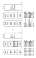
リソースユニットの帯域幅(あるいはサブキャリア数)は、各リソースユニットで共通でもよいし、リソースユニットごとに帯域幅(あるいはサブキャリア数)が異なってもよい。図3に、1つのチャネル内におけるリソースユニットの配置パターン例を模式的に示す。紙面に沿って横方向が周波数領域方向に対応する。図3(A)は、同じ帯域幅の複数のリソースユニット(RU#1、RU#2、・・・RU#K)を配置した例を示す。図3(B)は、図3(A)より大きな帯域幅の複数のリソースユニット(RU#11−1、RU#11−2、・・・、RU#11−L)を配置した例を示す。図3(C)は3種類以上の帯域幅のリソースユニットを配置した例を示す。リソースユニット(RU#12−1、RU#12−2)が最も大きな帯域幅を有し、リソースユニットRU#11−(L−1)は図3(B)のリソースユニットと同じ帯域幅、リソースユニット(RU#K−1、RU#K)は図3(A)のリソースユニットと同じ帯域幅を有する。
The bandwidth (or the number of subcarriers) of the resource unit may be common to each resource unit, or the bandwidth (or the number of subcarriers) may be different for each resource unit. FIG. 3 schematically shows an example of the arrangement pattern of resource units in one channel. The horizontal direction along the plane of the paper corresponds to the frequency domain direction. FIG. 3A shows an example in which a plurality of resource units (
一例として、20MHzチャネル幅全体を使う場合、20MHzチャネル幅内に配置される256個のサブキャリア(トーン)に対し、リソースユニットが26個で設定できる。つまり、20MHzチャネル幅では9つのリソースユニットが設定され、リソースユニットの帯域幅としては2.5MHz幅より小さくなる。40MHzチャネル幅では、一例として、リソースユニットは18個設定される。80MHzチャネル幅では、一例として、リソースユニットは、37個設定される。これを発展させると、例えば160MHzチャネル幅または80+80MHzチャネル幅では、74個のリソースユニットが設定される。もちろんリソースユニットの幅は特定の値に制限されず、様々なサイズのリソースユニットを配置することもできる。 As an example, when the entire 20 MHz channel width is used, 26 resource units can be set for 256 subcarriers (tones) arranged within the 20 MHz channel width. That is, nine resource units are set in the 20 MHz channel width, and the resource unit bandwidth is smaller than the 2.5 MHz width. In the 40 MHz channel width, 18 resource units are set as an example. In the 80 MHz channel width, as an example, 37 resource units are set. When this is developed, 74 resource units are set in the 160 MHz channel width or 80 + 80 MHz channel width, for example. Of course, the width of the resource unit is not limited to a specific value, and resource units of various sizes can be arranged.
なお、各端末が使用するリソースユニット数は、特定の値に制限されず、1つまたは複数のリソースユニットを用いてもよい。端末が複数のリソースユニットを用いる場合、周波数的に連続する複数のリソースユニットをボンディングして1つのリソースユニットとして用いてもよいし、離れた箇所にある複数のリソースユニットを用いることを許容してもよい。図3(B)のリソースユニット#11−1は、図3(A)のリソースユニット#1と#2をボンディングしたリソースユニットの一例と考えても良い。
Note that the number of resource units used by each terminal is not limited to a specific value, and one or a plurality of resource units may be used. When a terminal uses a plurality of resource units, a plurality of resource units that are continuous in frequency may be bonded to be used as one resource unit, or a plurality of resource units in remote locations may be used. Also good. The resource unit # 11-1 in FIG. 3B may be considered as an example of a resource unit obtained by bonding the
1つのリソースユニット内のサブキャリアは周波数領域で連続していてもよいし、非連続に配置された複数のサブキャリアからリソースユニットを定義してもよい。OFDMAで使用するチャネルは1つに限定されず、チャネルMに加えて、周波数領域で離れた位置に配置された別のチャネル(図2ではチャネルNを参照)内にも、チャネルMと同様にしてリソースユニットを確保し、チャネルMとチャネルNの両方内のリソースユニットを用いてもよい。チャネルMとチャネルNとでリソースユニットの配置方法は同じであっても、異なってもよい。1つのチャネルの帯域幅は、一例として、上述のように、20MHz、40MHz、80MHz、160MHzなどであるが、これらに限定されない。3つ以上のチャネルを用いることも可能である。なお、チャネルMとチャネルNをまとめて1つのチャネルとして考えることも可能である。 The subcarriers in one resource unit may be continuous in the frequency domain, or a resource unit may be defined from a plurality of subcarriers arranged discontinuously. The number of channels used in OFDMA is not limited to one. In addition to channel M, another channel (see channel N in FIG. 2) arranged at a position distant from the frequency domain may be used in the same manner as channel M. Resource units may be secured and resource units in both channel M and channel N may be used. The channel M and channel N may have the same or different resource unit arrangement method. As an example, the bandwidth of one channel is 20 MHz, 40 MHz, 80 MHz, 160 MHz, or the like as described above, but is not limited thereto. It is possible to use more than two channels. It is also possible to consider channel M and channel N as one channel.
なお、OFDMAを実施する端末は、少なくとも後方互換の対象となるレガシー端末での基本チャネル幅(IEEE802.11a/b/g/n/ac規格対応端末をレガシー端末とするなら20MHzチャネル幅)のチャネルで、フレームを含む物理パケットを受信および復号(復調および誤り訂正符号の復号等を含む)できるものとする。キャリアセンスに関しては、基本チャネル幅の単位で行うものとする。 A terminal that implements OFDMA has a channel with a basic channel width of at least a legacy terminal that is subject to backward compatibility (20 MHz channel width if a terminal that supports the IEEE 802.11a / b / g / n / ac standard is a legacy terminal). It is assumed that a physical packet including a frame can be received and decoded (including demodulation and decoding of an error correction code). Carrier sense is performed in units of basic channel width.
キャリアセンスは、CCA(Clear Channel Assessment)のビジー/アイドルに関する物理的なキャリアセンス(Physical Carrier Sense)と、受信したフレームの中に記載されている媒体予約時間に基づく仮想的なキャリアセンス(Virtual Carrier Sense)との両方を包含してもよい。後者のように、仮想的に媒体をビジーであると判定する仕組み、或いは、仮想的に媒体をビジーであるとする期間は、NAV(Network Allocation Vector)と呼ばれる。なお、チャネル単位で行ったCCAまたはNAVに基づくキャリアセンス情報は、チャネル内の全リソースユニットに共通に適用してもよい。例えばキャリアセンス情報がアイドルを示すチャネルに属するリソースユニットは、すべてアイドルと判断してもよい。 The carrier sense includes CCA (Clear Channel Accession) busy / idle physical carrier sense (Physical Carrier Sense) and virtual carrier sense (Virtual Carrier Sense) based on the medium reservation time described in the received frame. Sense) may be included. A mechanism for determining that a medium is virtually busy, such as the latter, or a period during which a medium is virtually busy is called a NAV (Network Allocation Vector). Note that the carrier sense information based on CCA or NAV performed for each channel may be commonly applied to all resource units in the channel. For example, all resource units belonging to a channel whose carrier sense information indicates idle may be determined as idle.
なお、OFDMAは、上述したリソースユニットベースのOFDMA以外に、チャネルベースでのOFDMAも可能である。この場合のOFDMAを、特にMU−MC(Multi−User Multi−Channel)と呼ぶことがある。MU−MCでは、クセスポイントが複数のチャネル(1つのチャネル幅は例えば20MHzなど)を複数の端末に割り当て、当該複数のチャネルを同時に用いて、複数端末宛て同時送信もしくは複数端末からの同時受信を行う。以降に説明するOFDMAでは、リソースユニットベースのOFDMAを想定するが、以降の説明のリソースユニットをチャネルに読み替えるなど、必要な読み替えを行うことで、チャネルベースのOFDMAの実施形態も実現可能である。 Note that OFDMA can be channel-based OFDMA in addition to the resource unit-based OFDMA described above. The OFDMA in this case is sometimes called MU-MC (Multi-User Multi-Channel). In MU-MC, the access point assigns a plurality of channels (one channel width is, for example, 20 MHz) to a plurality of terminals, and simultaneously uses the plurality of channels to simultaneously transmit to or receive from a plurality of terminals. Do. In the OFDMA described below, a resource unit-based OFDMA is assumed, but an embodiment of a channel-based OFDMA can be realized by performing necessary replacement such as replacing the resource unit described below with a channel.
以下の説明において、OFDMAを実施する能力を有する端末をOFDMA対応端末などと呼ぶことがある。当該能力を有さない端末をレガシー端末と呼ぶことがある。OFDMA通信を実施する能力を有効(Enable)または無効(Disable)に切り替え可能な場合、当該能力が有効になっている端末をOFDMA対応端末として考えればよい。 In the following description, a terminal having the ability to implement OFDMA may be referred to as an OFDMA compatible terminal. A terminal that does not have the capability may be referred to as a legacy terminal. When the capability of performing OFDMA communication can be switched between enabled (disabled) and disabled (disabled), a terminal with the enabled capability may be considered as an OFDMA compatible terminal.
図1に示されるように、端末(非基地局の端末及び基地局)に搭載される無線通信装置は、上位処理部90、MAC処理部10、PHY(Physical:物理)処理部50、MAC/PHY管理部60、アナログ処理部70(アナログ処理部1〜N)及びアンテナ80(アンテナ1〜N)を含む。Nは1以上の整数である。図では、N個のアナログ処理部と、N個のアンテナが、一対ずつ接続されているが、必ずしもこの構成に限定されるものではない。例えばアナログ処理部の個数が1つで、2つ以上のアンテナがこのアナログ処理部に共通に接続されてもよい。
As shown in FIG. 1, a wireless communication device mounted on a terminal (a non-base station terminal and a base station) includes a
MAC処理部10、MAC/PHY管理部60、及びPHY処理部50は、他の端末(基地局を含む)との通信に関する処理を行う制御部またはベースバンド集積回路の一形態に相当する。アナログ処理部70は、例えばアンテナ80を介して信号を送受信する無線通信部またはRF(Radio Frequency)集積回路の一形態に相当する。本実施形態に係る無線通信用集積回路は、当該ベースバンド集積回路(制御部)およびRF集積回路の少なくとも前者を含む。ベースバンド集積回路の機能は、CPU等のプロセッサで動作するソフトウェア(プログラム)によって行われてもよいし、ハードウェアによって行われてもよいし、ソフトウェアとハードウェアの両方によって行われてもよい。ソフトウェアはROM、RAM等のメモリ、ハードディスク、SSDなどの記憶媒体に格納してプロセッサにより読み出して実行してもよい。メモリはSRAM、DRAM等の揮発性メモリでも、NAND、MRAM等の不揮発性メモリでもよい。
The
上位処理部90は、MAC(Medium Access Control:媒体アクセス制御)層に対して上位層のための処理を行う。上位処理部90は、MAC処理部10との間で信号をやり取りできる。上位層としては、代表的なものとしては、TCP/IPやUDP/IP、さらにその上層のアプリケーション層などが挙げられるが、本実施形態はこれに限定されない。上位処理部90は、MAC層と上位層との間でデータをやり取りするためのバッファを備えていてもよい。上位処理部90を介して有線インフラに接続するようになっていてもよい。バッファは、メモリでもよいし、SSD、ハードディスク等でもよい。バッファがメモリの場合、当該メモリはSRAM、DRAM等の揮発性メモリでも、NAND、MRAM等の不揮発性メモリでもよい。
The
MAC処理部10は、MAC層のための処理を行う。前述のように、MAC処理部10は、上位処理部90との間で信号をやり取りできる。更に、MAC処理部10は、PHY処理部50との間で、信号をやり取りできる。MAC処理部10は、MAC共通処理部20と送信処理部30と受信処理部40を含む。
The
MAC共通処理部20は、MAC層での送受信に共通する処理を行う。MAC共通処理部20は、上位処理部90、送信処理部30、受信処理部40及びMAC/PHY管理部60と接続され、夫々との間で信号のやり取りをする。
The MAC
送信処理部30及び受信処理部40は、相互に接続している。また、送信処理部30及び受信処理部40は、それぞれMAC共通処理部20及びPHY処理部50に接続している。送信処理部30は、MAC層での送信処理を行う。受信処理部40は、MAC層での受信処理を行う。
The
PHY処理部50は、物理層(PHY層)のための処理を行う。前述のように、PHY処理部50は、MAC処理部10との間で信号をやり取りできる。PHY処理部50は、アナログ処理部70を介してアンテナ80に接続されている。
The
MAC/PHY管理部60は、上位処理部90、MAC処理部10(より詳細には、MAC共通処理部20)及びPHY処理部50の夫々と接続されている。MAC/PHY管理部60は、無線通信装置におけるMAC動作及びPHY動作を管理する。
The MAC /
アナログ処理部70は、アナログ/デジタル及びデジタル/アナログ(AD/DA)変換器およびRF(Radio Frequency)回路を含み、PHY処理部50からのデジタル信号を所望の周波数のアナログ信号に変換してアンテナ80から送信、またアンテナ80から受信した高周波のアナログ信号をデジタル信号に変換する。なお、ここでは、AD/DA変換をアナログ処理部70で行っているが、PHY処理部50にAD/DA変換機能を持たせる構成も可能である。
The
本実施形態に係る無線通信装置は、1チップ内にアンテナ80を構成要素として含む(一体化する)ことで、このアンテナ80の実装面積を小さく抑えることができる。更に、本実施形態に係る無線通信装置は、図1に示されるように、送信処理部30及び受信処理部40が、N本のアンテナ80を共用している。送信処理部30及び受信処理部40がN本のアンテナ80を共用することにより、図1の無線通信装置を小型化できる。なお、本実施形態に係る無線通信装置は、図1に例示されたものと異なる構成を備えても勿論よい。
The wireless communication apparatus according to the present embodiment includes (integrates) the
無線媒体からの信号受信に際して、アナログ処理部70は、アンテナ80が受信したアナログ信号を、PHY処理部50が処理可能な基底帯域(Baseband)の信号に変換し、さらにデジタル信号に変換する。PHY処理部50は、アナログ処理部70からデジタルの受信信号を受け取り、その受信レベルを検出する。検出した受信レベルを、キャリアセンスレベル(閾値)と比較し、受信レベルが、キャリアセンスレベル以上であれば、PHY処理部50は媒体(CCA:Clear Channel Assessment)がビジーであるということを示す信号を、MAC処理部10(より正確には、受信処理部40)へ出力する。受信レベルが、キャリアセンスレベル未満であれば、PHY処理部50は、媒体(CCA)がアイドルであるということを示す信号を、MAC処理部10(より正確には受信処理部40)へ出力する。
When receiving a signal from the wireless medium, the
PHY処理部50は、受信信号に対し、復号(復調および誤り訂正符号の復号等を含む)処理、プリアンブルを含む物理ヘッダ(PHYヘッダ)を取り除く処理などを行って、ペイロードを抽出する。IEEE802.11規格ではこのペイロードをPHY側ではPSDU(physical layer convergence procedure (PLCP) service data unit)と呼んでいる。PHY処理部50は、抽出したペイロードを受信処理部40に渡し、受信処理部40はこれをMACフレームとして扱う。IEEE802.11規格では、このMACフレームを、MPDU(medium access control (MAC) protocol data unit)と呼んでいる。加えて、PHY処理部50は、受信信号を受信開始した際に、その旨を受信処理部40に通知し、また受信信号を受信終了した際に、その旨を受信処理部40に通知する。また、PHY処理部50は、受信信号が正常に物理パケット(PHYパケット)として復号できた場合(エラーを検出しなければ)、受信信号の受信終了を通知すると共に、媒体がアイドルであるということを示す信号を、受信処理部40に渡す。PHY処理部50は、受信信号にエラーを検出した場合には、エラー種別に即した適切なエラーコードをもって、受信処理部40にエラーを検出したことを通知する。また、PHY処理部50は、媒体がアイドルになったと判定した時点で、媒体がアイドルであることを示す信号を受信処理部40に通知する。
The
MAC共通処理部20は、上位処理部90から送信処理部30への送信データの受け渡し、及び受信処理部40から上位処理部90への受信データの受け渡しを、夫々仲介する。IEEE802.11規格では、このMACデータフレームの中のデータを、MSDU(medium access control (MAC) service data unit)と呼んでいる。また、MAC共通処理部20は、MAC/PHY管理部60からの指示を一旦受け取り、当該指示を送信処理部30及び受信処理部40に、それぞれ適したものに変換して出力する。
The MAC
MAC/PHY管理部60は、例えばIEEE802.11規格におけるSME(Station Management Entity)に相当する。その場合、MAC/PHY管理部60とMAC共通処理部20との間のインターフェースは、IEEE802.11規格におけるMLME SAP(MAC subLayer Managament Entity Service Access Point)に相当し、MAC/PHY管理部60とPHY処理部50との間のインターフェースは、IEEE802.11無線LAN(Local Area Network)におけるPLME SAP(Physical Layer Management Entity Service Access Point)に相当する。
The MAC /
なお、図1において、MAC/PHY管理部60は、MAC管理のための機能部とPHY管理のための機能部とが一体であるかのように描かれているが、分けて実装されてもよい。
In FIG. 1, the MAC /
MAC/PHY管理部60は、管理情報ベース(Management Information Base:MIB)を保持する。MIBは、自端末の能力や各種機能が夫々有効か無効かなどの各種情報を保持する。例えば、自端末が、OFDMA対応か否か、また、OFDMA対応の場合にOFDMAを実施する能力の機能のオン/オフの情報も保持されていてもよい。MIBを保持・管理するためのメモリは、MAC/PHY管理部60に内包させてもよいし、MAC/PHY管理部60に内包せずに別に設けるようにしてもよい。MIBを保持・管理するためのメモリをMAC/PHY管理部60とは別に設ける場合に、MAC/PHY管理部60は、その別のメモリを参照でき、またメモリ内の書き換え可能なパラメータに関しては書き換えを行うことができる。メモリはSRAM、DRAM等の揮発性メモリでも、NAND、MRAM等の不揮発メモリでもよい。また、メモリでなく、SSDやハードディスク等の記憶装置でもよい。基地局では、非基地局としての他の端末のこれらの情報も、当該端末からの通知により、取得することができる。その場合、MAC/PHY管理部60は、他の端末に関する情報を参照・書き換えが可能になっている。あるいはこれらの他の端末に関する情報を記憶するためのメモリは、MIBとは別に保持・管理するようにしてもよい。その場合、MAC/PHY管理部60あるいはMAC共通処理部20が、その別のメモリを参照・書き換えが可能なようにする。また基地局のMAC/PHY管理部60は、OFDMA(UL−OFDMAまたはDL−OFDMA)の実施にあたり、非基地局としての端末に関する各種の情報、または端末からの要求に基づき、OFDMA用のリソースユニットを同時に割り当てる端末を選定する選定機能も備えていてもよい。また、MAC/PHY管理部60またはMAC処理部10は、送信するMACフレームおよび物理ヘッダに適用する伝送レートを管理してもよい。また基地局のMAC/PHY管理部60は、基地局がサポートするレートセットであるサポートレートセットを定義および管理してもよい。サポートレートセットは、基地局に接続する端末がサポートすることが必須であるレートと、オプションのレートを含んでもよい。
The MAC /
MAC処理部10は、データフレーム、制御フレーム及び管理フレームの3種類のMACフレームを扱い、MAC層において規定される各種処理を行う。ここで、3種類のMACフレームについて説明する。
The
管理フレームは、他の端末との間の通信リンクの管理のために用いられる。管理フレームとしては、例えば、IEEE802.11規格におけるBasic Service Set(BSS)である無線通信グループを形成するために、グループの属性及び同期情報を報知するビーコン(Beacon)フレームがある。また、認証のためにまたは通信リンク確立のために交換されるフレームなどもある。なお、ある端末が、もう一台の端末と互いに無線通信を実施するために必要な情報交換を済ませた状態を、通信リンクが確立していると、ここでは表現する。必要な情報交換として、例えば、自端末が対応する機能(例えばOFDMA方式への対応や各種能力など)の通知や、方式の設定に関するネゴシエーションなどがある。管理フレームは、送信処理部30が、MAC/PHY管理部60からMAC共通処理部20を介して受けた指示に基づいて生成する。
The management frame is used for management of communication links with other terminals. An example of the management frame is a beacon frame that broadcasts group attributes and synchronization information to form a wireless communication group that is a Basic Service Set (BSS) in the IEEE 802.11 standard. There are also frames exchanged for authentication or for establishing a communication link. Here, a state in which a certain terminal has exchanged information necessary for performing wireless communication with another terminal is expressed as an established communication link. Necessary information exchange includes, for example, notification of functions supported by the terminal (for example, support for OFDMA system, various capabilities, etc.) and negotiation for system setting. The management frame is generated based on an instruction received by the
管理フレームに関連して、送信処理部30は、他の端末に管理フレームを介して各種情報を通知する通知手段を有する。例えば。非基地局としての端末の通知手段は、OFDMA対応端末、IEEE802.11n対応端末、IEEE802.11ac対応端末のいずれに対応しているかの情報を、管理フレームに入れて送信することで、基地局に自端末の種別を通知してもよい。この管理フレームとしては、例えば端末が基地局との間で認証を行う手順の一つであるアソシエーションプロセスで用いられるAssociation Requestフレームや、あるいはリアエソシエーションプロセスで用いられるReassociation Requestフレームがある。基地局の通知手段は、非基地局の端末に、OFDMA通信への対応可否の情報を、管理フレームを介して通知してもよい。これに用いる管理フレームとしては、例えばBeaconフレームや、非基地局端末が送信したProbe Requestフレームに対する応答であるProbe Responseフレームがある。基地局は、自装置に接続している端末群をグループ化する機能を有していてもよい。基地局の上記の通知手段は、各端末にそれぞれが属するグループのグループ識別子であるグループIDを、管理フレームを介して通知してもよい。この管理フレームとしては、例えばGroup ID Managementフレームがある。グループIDは、例えばIEEE Std 802.11ac−2013でダウンリンクMU−MIMO(Multi−User Multi−Input Multi−Output)(DL−MU−MIMO)のために規定されたグループID(6ビット)をOFDMAの場合も包含するように拡張したものでもよいし、これとは別の方法で定義したグループIDでもよい。
In relation to the management frame, the
ここでアソシエーションID(AID)について説明する。AIDは、端末が基地局に接続し、基地局下のBSSでデータフレーム交換が行えるようにするためのアソシエーションプロセスで、基地局から割り当てられる端末の識別子(端末識別子)である。アソシエーションプロセスは具体的には、端末から基地局宛てにAssociation Requestフレームを送信し、基地局から端末宛てにAssociation Responseフレームを送信し、Association Responseフレームの中の端末Status Codeフィールドが”0”すなわちsuccessである場合に成功するプロセスである。Association Requestフレーム、Association Responseフレームの双方には、送信端末の通信能力(Capability)が入れられており、それにより、受信した双方が相手の通信能力を把握する。Association Responseフレームの中の端末Status Codeフィールドが”0”すなわちsuccessである場合には、同フレーム中のAIDフィールド(16ビット)からAIDを抽出し、送信先端末のAIDとして使われることになる。すなわち、この時点で、基地局から端末にAIDが割り当てられたことになり、端末としてはAIDが有効の状態となる。当該基地局が端末との間で接続(Association)している状態では、端末のAIDが有効である。一方、基地局から当該端末にDisassociationフレームを送信し、当該端末が受信すると、あるいは当該端末から基地局にDisassociationフレームを送信すると、当該端末のAIDは無効(null)となる。どの基地局ともアソシエーションプロセスを経ていない状態の端末でも当然、AIDは無効である。AIDが無効の状態は、AIDが未指定の状態とも言うこともできる。 Here, the association ID (AID) will be described. AID is an identifier (terminal identifier) of a terminal assigned from the base station in an association process for allowing the terminal to connect to the base station and exchange data frames with the BSS under the base station. Specifically, in the association process, an association request frame is transmitted from the terminal to the base station, an association response frame is transmitted from the base station to the terminal, and the terminal status code field in the association response frame is “0”, ie, success. Is a successful process. Both the Association Request frame and the Association Response frame contain the communication capability (capability) of the transmitting terminal, so that both sides receive the communication capability of the other party. When the terminal status code field in the association response frame is “0”, that is, success, the AID is extracted from the AID field (16 bits) in the frame and used as the AID of the transmission destination terminal. That is, at this time, an AID is assigned to the terminal from the base station, and the AID becomes valid for the terminal. In a state where the base station is connected to the terminal (Association), the AID of the terminal is valid. On the other hand, when a Dissociation frame is transmitted from the base station to the terminal and the terminal receives it, or when a Dissociation frame is transmitted from the terminal to the base station, the AID of the terminal becomes null. Of course, the AID is invalid for a terminal that has not undergone the association process with any base station. It can be said that the state where the AID is invalid is a state where the AID is not specified.
受信処理部40は、他の端末から管理フレームを介して各種情報を受信する受信手段を有する。一例として、基地局の受信手段は、非基地局としての端末からOFDMAの対応可否の情報を受信してもよい。また、当該非基地局としての端末がレガシー端末(IEEE802.11a/b/g/n/ac規格対応端末など)の場合に、対応可能なチャネル幅(利用可能な最大のチャネル幅)の情報を受信してもよい。当該端末の受信手段は、基地局からOFDMA対応可否の情報を受信してもよい。
The
上述した管理フレームを介して送受信する情報の例は、ほんの一例であり、その他種々の情報を、管理フレームを介して、端末(基地局を含む)間で送受信することが可能である。例えばOFDMA対応端末は、自身がUL−OFDMA送信で使用することを希望するリソースユニット、または、チャネル、またはこれらの両方を、キャリアセンスで非干渉のチャネル、または、非干渉のリソースユニット、またはこれらの両方から、選択してもよい。そして、選択したリソースユニットまたはチャネルまたはこれらの両方に関する情報を、基地局に通知してもよい。この場合、基地局は当該情報に基づき、UL−OFDMA通信のためのリソースユニット割り当てを各OFDMA対応端末に対して行ってもよい。なお、OFDMA通信で利用するチャネルは、無線通信システムとして利用可能な全てのチャネルであっても、一部(1つまたは複数)のチャネルであってもよい。 The example of the information transmitted / received via the management frame described above is only an example, and various other information can be transmitted / received between terminals (including base stations) via the management frame. For example, an OFDMA-capable terminal uses a resource unit or channel that it wants to use for UL-OFDMA transmission, or both, a channel that is non-interfering with carrier sense, or a non-interfering resource unit, or these You may choose from both. Then, the base station may be notified of information regarding the selected resource unit and / or channel. In this case, the base station may perform resource unit allocation for UL-OFDMA communication for each OFDMA-compatible terminal based on the information. Note that the channels used in OFDMA communication may be all channels that can be used as a wireless communication system or some (one or more) channels.
データフレームは、他の端末との間で通信リンクが確立した状態で、データを当該他の端末に送信するために用いられる。例えばユーザのアプリケーション操作によって、端末においてデータが生成され、当該データがデータフレームによって搬送される。具体的には、生成されたデータは、上位処理部90からMAC共通処理部20を介して送信処理部30に渡され、送信処理部30でデータをフレームボディフィールドに入れ、当該フレームボディフィールドにMACヘッダを付加してデータフレームが生成される。そして、PHY処理部50で、データフレームに物理ヘッダを付加して物理パケットが生成され、物理パケットが、アナログ処理部70及びアンテナ80を介して送信される。また、PHY処理部50で物理パケットを受信すると、物理ヘッダに基づき物理層の処理を行ってMACフレーム(ここではデータフレーム)を抽出し、データフレームを受信処理部40に渡す。受信処理部40は、データフレームを受けると(受信したMACフレームがデータフレームであると把握すると)、そのフレームボディフィールドの情報をデータとして抽出し、抽出したデータを、MAC共通処理部20を介して上位処理部90に渡す。この結果、データの書き込み、再生などのアプリケーション上の動作が生じる。
The data frame is used to transmit data to the other terminal in a state where a communication link is established with the other terminal. For example, data is generated in the terminal by a user's application operation, and the data is carried by a data frame. Specifically, the generated data is passed from the
制御フレームは、管理フレーム及びデータフレームを、他の無線通信装置との間で送受信(交換)するときの制御のために用いられる。制御フレームとしては、例えば、管理フレーム及びデータフレームの交換を開始する前に、無線媒体を予約するために他の無線通信装置との間で交換するRTS(Request to Send)フレーム、CTS(Clear to Send)フレームなどがある。また、他の制御フレームとして、受信した管理フレーム及びデータフレームの送達確認のための送達確認応答フレームがある。送達確認応答フレームの例として、ACK(Acknowledgement)フレーム、BA(BlockACK)フレームなどがある。CTSフレームも、RTSフレームの応答として送信するため、送達確認応答を表すフレームであるとも言える。CF−Endフレームも、制御フレームの1つである。CF−Endフレームは、CFP(Contention Free Period)の終了をアナウンスするフレーム、つまり、無線媒体へのアクセスを許可するフレームである。これらの制御フレームは送信処理部30で生成される。受信したMACフレームへの応答として送信される制御フレーム(CTSフレームやACKフレーム、BAフレームなど)に関しては、受信処理部40で応答フレーム(制御フレーム)の送信の必要を判断して、フレーム生成に必要な情報(制御フレームの種別、RA(Receiver Address)フィールド等に設定する情報など)を送信指示とともに送信処理部30に出す。送信処理部30は、当該フレーム生成に必要な情報と送信指示に基づき、適切な制御フレームを生成する。
The control frame is used for control when a management frame and a data frame are transmitted / received (exchanged) with another wireless communication apparatus. As the control frame, for example, before starting the exchange of the management frame and the data frame, an RTS (Request to Send) frame exchanged with another wireless communication device to reserve a wireless medium, a CTS (Clear to Send) frame. As another control frame, there is a delivery confirmation response frame for confirming delivery of the received management frame and data frame. Examples of the delivery confirmation response frame include an ACK (Acknowledgement) frame and a BA (BlockACK) frame. Since the CTS frame is also transmitted as a response to the RTS frame, it can be said that the CTS frame represents a delivery confirmation response. The CF-End frame is also one of the control frames. The CF-End frame is a frame that announces the end of CFP (Contents Free Period), that is, a frame that permits access to the wireless medium. These control frames are generated by the
MAC処理部10は、CSMA/CA(Carrier Sense Multiple Access with Carrier Avoidance)に基づきMACフレームを送信する場合、無線媒体上でのアクセス権(送信権)を獲得する必要がある。送信処理部30は、受信処理部40からのキャリアセンス情報に基づいて、送信タイミングを計る。送信処理部30は、係る送信タイミングに従って、PHY処理部50に送信指示を与えて、さらにMACフレームを渡す。送信指示に加えて、送信処理部30は、送信に使用される変調方式及び符号化方式を合わせて指示してもよい。これらに加えて、送信処理部30は、送信電力を指示してもよい。MAC処理部10は、アクセス権(送信権)獲得後、媒体を占有可能な時間(Transmission Opportunity;TXOP)が得られると、QoS(Quality of Service)属性などの制限を伴うものの、他の無線通信装置との間でMACフレームを連続して交換できる。TXOPは、例えば、無線通信装置がCSMA/CAに基づき所定のフレーム(例えばRTSフレーム)を送信し、他の無線通信装置から応答フレーム(例えばCTSフレーム)を正しく受信した場合に、獲得される。この所定のフレームが、当該他の無線通信装置によって受信されると、当該他の無線通信装置は、最小フレーム間隔(Short InterFrame Space;SIFS)後に、上記応答フレームを送信する。また、RTSフレームを用いないでTXOPを獲得する方法として、例えば直接ユニキャストで、送達確認応答フレームの送信を要求するデータフレーム(後述のようにフレームが連接された形状のフレーム、またはペイロードが連接された形状のフレームであってもよい)あるいは管理フレームを送信し、それに対する送達確認応答フレーム(ACKフレームやBlockACKフレーム)を正しく受信する場合がある。あるいは、他の無線通信装置に送達確認応答フレームの送信を要求しないフレームであって、そのフレームのDuration/IDフィールドに当該フレームの送信に要する時間以上の期間を設定したものを送信した場合には、当該フレームを送信した段階からDuration/IDフィールドに記載された期間のTXOPを獲得したと解釈してもよい。
When the
受信処理部40は、上述したキャリアセンス情報を管理する。このキャリアセンス情報は、PHY処理部50から入力される媒体(CCA)のビジー/アイドルに関する物理的なキャリアセンス(Physical Carrier Sense)情報と、受信フレームの中に記載されている媒体予約時間に基づく仮想的なキャリアセンス(Virtual Carrier Sense)情報との両方を包含する。いずれか一方のキャリアセンス情報がビジーを示すならば、媒体がビジーであるとみなされ、その間送信は禁止される。なお、IEEE802.11規格において、媒体予約時間は、MACヘッダの中のDuration/IDフィールドに記載される。MAC処理部10は、他の無線通信装置宛ての(自己宛てでない)MACフレームを受信した場合に、当該MACフレームを含む物理パケットの終わりから媒体予約時間に亘って、媒体が仮想的にビジーであると判定する。このような仮想的に媒体をビジーであると判定する仕組み、或いは、仮想的に媒体をビジーであるとする期間は、NAV(Network Allocation Vector)と呼ばれる。媒体予約時間は無線媒体へのアクセスの抑制を指示する期間の長さ、すなわち無線媒体へのアクセスを延期させる期間の長さを表しているといえる。
The
ここで、データフレームは、複数のMACフレームもしくは複数のMACフレームのペイロード部分を連接するようになっていてもよい。前者はIEEE802.11規格ではA(Aggregated)−MPDU、後者はA(Aggregated)−MSDU(MAC service data unit)と呼ばれる。A−MPDUの場合は、PSDUの中に複数のMPDUが連接されることになる。またデータフレームのみならず、管理フレームや制御フレームも連接対象となる。A−MSDUの場合には、1つのMPDUのフレームボディ中に、複数のデータペイロードであるMSDUが連接されることになる。A−MPDU、およびA−MSDUのいずれも、複数のMPDUの連接、および複数のMSDUの連接を、受信側端末で適切に分離できるように、データフレームに区切り情報(長さ情報など)が格納されている。A−MPDUおよびA−MSDUの両方を組み合わせて用いてもよい。またA−MPDUは、複数のMACフレームではなく、1つのMACフレームのみを対象としてもよく、この場合も区切り情報をデータフレームに格納する。また、A−MPDUなどを受信した場合は、連接されている複数のMACフレームに対する応答をまとめて送信する。この場合の応答には、ACKフレームではなく、BA(BlockACK)フレームが用いられる。以降の説明および図では、MPDUの表記を用いることがあるが、これは、上述したA−MPDUまたはA−MSDUの場合も含むものとする。 Here, the data frame may be configured to connect a plurality of MAC frames or payload portions of a plurality of MAC frames. The former is called A (Aggregated) -MPDU in the IEEE 802.11 standard, and the latter is called A (Aggregated) -MSDU (MAC service data unit). In the case of A-MPDU, a plurality of MPDUs are connected in the PSDU. In addition to data frames, management frames and control frames are also subject to concatenation. In the case of A-MSDU, a plurality of data payloads MSDU are concatenated in the frame body of one MPDU. For both A-MPDU and A-MSDU, delimiter information (length information, etc.) is stored in the data frame so that concatenation of a plurality of MPDUs and a concatenation of a plurality of MSDUs can be appropriately separated at the receiving terminal. Has been. Both A-MPDU and A-MSDU may be used in combination. In addition, the A-MPDU may target only one MAC frame instead of a plurality of MAC frames. In this case, the delimiter information is stored in the data frame. In addition, when A-MPDU or the like is received, responses to a plurality of connected MAC frames are collectively transmitted. In this case, a BA (BlockACK) frame is used instead of an ACK frame. In the following description and figures, the MPDU notation may be used, but this also includes the case of the above-described A-MPDU or A-MSDU.
IEEE802.11規格では、基地局が中心となり構成するBSS(これをインフラストラクチャ(Infrastructure)BSSと呼ぶ)に、非基地局の端末が加入し、BSS内でデータフレームの交換ができるようになるために経る手順(procedure)が、段階的に複数規定されている。例えば、アソシエーション(association)という手順があり、非基地局の端末から、当該端末が接続を要求する基地局に対して、アソシエーション要求(Association Request)フレームを送信する。基地局は、アソシエーション要求フレームに対するACKフレームを送信後、アソシエーション要求フレームに対する応答であるアソシエーション応答(Association Response)フレームを送信する。 According to the IEEE802.11 standard, a non-base station terminal joins a BSS (this is called an infrastructure BSS) formed mainly by a base station, and data frames can be exchanged within the BSS. A plurality of procedures are defined in stages. For example, there is a procedure called association, and an association request (Association Request) frame is transmitted from a terminal of a non-base station to a base station to which the terminal requests connection. The base station transmits an ACK frame for the association request frame, and then transmits an association response frame that is a response to the association request frame.
端末はアソシエーション要求フレームに自端末の能力(capability)を格納し、それを送信することで基地局に自端末の能力の通知をすることができる。例えば、端末はアソシエーション要求フレームの中に、自端末が対応可能なチャネルまたはリソースユニットまたはこれらの両方や、自端末が対応する規格を特定するための情報を入れて送信してもよい。他の基地局へ再接続するための再アソシエーション(reassociation)という手順で送信するフレームにも、この情報を設定するようにしてもよい。この再アソシエーションの手順では、端末から、再接続を要求する他の基地局に対して、再アソシエーション要求(Reassociation Request)フレームを送信する。当該他の基地局は、再アソシエーション要求フレームに対するACKフレームを送信後、再アソシエーション要求フレームに対する応答である再アソシエーション応答(Reassociation Response)フレームを送信する。 The terminal stores the capability of its own terminal in the association request frame, and can notify the base station of the capability of its own terminal by transmitting it. For example, the terminal may transmit the association request frame with information for specifying a channel and / or resource unit that can be supported by the terminal, and a standard that the terminal supports. You may make it set this information also to the flame | frame transmitted in the procedure of the reassociation (reassociation) for reconnecting to another base station. In this reassociation procedure, a terminal transmits a reassociation request (Reassociation Request) frame to another base station that requests reconnection. The other base station transmits an ACK frame for the re-association request frame, and then transmits a re-association response frame that is a response to the re-association request frame.
管理フレームとして、アソシエーション要求フレームおよび再アソシエーション要求フレーム以外にも、ビーコンフレーム、プローブ応答(Probe Response)フレームなどを用いてもよい。ビーコンフレームは基本的に基地局が送信するもので、BSSの属性を示すパラメータとともに、基地局自身の能力を通知するパラメータも格納できる。そこで、この基地局自身の能力を通知するパラメータとして、基地局がOFDMAへの対応可否の情報を加えるようにしてもよい。また他のパラメータとして、基地局のサポートレート(Supported Rate)の情報を通知してもよい。サポートレートは、基地局が形成するBSSに参加する端末が対応必須のレートと、オプションのレートとを含んでもよい。プローブ応答フレームは、ビーコンフレームを送信する端末からプローブ要求(Probe Request)フレームを受信すると、それに応答して送信するフレームである。プローブ応答フレームは、基本的にはビーコンフレームと同一の内容を通知するものであるため、プローブ応答フレームを用いても基地局は、プローブ要求フレームを送信した端末に、自局の能力を通知することができる。OFDMA対応端末にこの通知を行うことで、端末が例えば自端末のOFDMA通信の機能を有効にするといった動作を行ってもよい。 In addition to the association request frame and the reassociation request frame, a beacon frame, a probe response (Probe Response) frame, or the like may be used as the management frame. The beacon frame is basically transmitted by the base station, and can store a parameter indicating the BSS attribute and a parameter notifying the base station itself. Therefore, the base station may add information indicating whether or not the base station is capable of supporting OFDMA as a parameter for reporting the capability of the base station itself. Moreover, you may notify the information of the support rate (Supported Rate) of a base station as another parameter. The support rate may include a rate that is mandatory for terminals participating in the BSS formed by the base station and an optional rate. The probe response frame is a frame that is transmitted in response to reception of a probe request frame from a terminal that transmits a beacon frame. Since the probe response frame basically notifies the same content as the beacon frame, the base station notifies the terminal that transmitted the probe request frame of the capability of the own station even if the probe response frame is used. be able to. By performing this notification to the OFDMA compatible terminal, the terminal may perform an operation such as, for example, enabling the function of the OFDMA communication of the terminal itself.
なお、端末は自端末の能力について基地局へ通知する情報として、基地局のサポートレートのうち自端末が実行可能なレートの情報を通知してもよい。ただし、サポートレートのうち必須のレートについては、基地局へ接続する端末はその必須のレートを実行する能力を有するものとする。 In addition, a terminal may notify information on a rate that can be executed by the terminal among the support rates of the base station as information to notify the base station of the capability of the terminal. However, with regard to an indispensable rate among the support rates, it is assumed that a terminal connected to the base station has an ability to execute the essential rate.
なお、上記で扱った情報のうち、ある情報を通知することで、別の情報の内容が決まるものがあれば、通知を省略できる。例えば、ある新しい規格あるいは仕様に対応する能力を定義し、それに対応していれば自ずとOFDMA対応端末である、という場合を考える。この場合、上記ある情報として、規格あるいは仕様に対応する能力の有を通知し、上記別の情報として、OFDMA対応端末であることの通知を明示的に行わなくてもよい。 Of the information handled above, if there is information that determines the content of other information by notifying some information, the notification can be omitted. For example, let us consider a case where an ability corresponding to a certain new standard or specification is defined, and if it corresponds to this, it is an OFDMA compatible terminal. In this case, the presence of capability corresponding to the standard or specification may be notified as the certain information, and the notification that the terminal is an OFDMA-compatible terminal may not be explicitly performed as the other information.
図4に、本実施形態に従った無線通信システムを示す。このシステムは、基地局(AP:Access Point)100と、複数の端末(STA:STAtion)1〜8とを備える。基地局100と、配下の端末1〜8により、BSS(Basic Service Set)1が形成される。このシステムは、CSMA/CA(Carrier Sense Multiple Access with Carrier Avoidance)を用いるIEEE802.11規格に準じた無線LANシステムである。なお、BSS1内に本実施形態に係る端末(OFDMA対応端末)以外のレガシー端末(IEEE802.11a/b/g/n/ac規格対応端末など)が存在していてもかまわない。
FIG. 4 shows a wireless communication system according to the present embodiment. This system includes a base station (AP: Access Point) 100 and a plurality of terminals (STA: STATION) 1 to 8. The base station 100 and
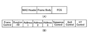
図5(A)は、MACフレームの基本的なフォーマット例を示す。本実施形態に係るデータフレーム、管理フレームおよび制御フレームは、このようなフレームフォーマットをベースとする。本フレームフォーマットは、MACヘッダ(MAC header)、フレームボディ(Frame body)及びFCSの各フィールドを含む。MACヘッダは、図5(B)に示すように、Frame Control、Duration/ID、Address1、Address2、Address3, Sequence Control、QoS Control及び HT(High Throughput) controlの各フィールドを含む。 FIG. 5A shows a basic format example of a MAC frame. The data frame, management frame, and control frame according to the present embodiment are based on such a frame format. This frame format includes fields of a MAC header, a frame body, and an FCS. 5B, each field of Frame Control, Duration / ID, Address1, Address2, Address3, Sequence Control, QoS Control, and HT (High Thruput) control is included.
これらのフィールドは必ずしもすべて存在する必要はなく、一部のフィールドが存在しない場合もあり得る。例えばAddress3フィールドが存在しない場合もある。また、QoS ControlおよびHT Controlフィールドの両方または一方が存在しない場合もある。またフレームボディフィールドが存在しない場合もあり得る。また図5には示されていない他のフィールドが存在してもよい。例えば、Address4フィールドがさらに存在してもよい。後述するトリガーフレームの場合、共通情報フィールドおよび端末情報フィールドが、フレームボディフィールドまたはMACヘッダに存在してもよい。 All of these fields need not be present, and some fields may not be present. For example, the Address3 field may not exist. In addition, there may be cases where both or one of the QoS Control and HT Control fields does not exist. There may also be no frame body field. There may also be other fields not shown in FIG. For example, an Address4 field may further exist. In the case of a trigger frame described later, a common information field and a terminal information field may be present in the frame body field or the MAC header.
Address1のフィールドには、受信先アドレス(Receiver Address;RA)が、Address2のフィールドには送信元アドレス(Transmitter Address;TA)が入り、Address3のフィールドにはフレームの用途に応じてBSSの識別子であるBSSID(Basic Service Set IDentifier)か、あるいはTAが入る。BSSIDは、全てのBSSIDを対象とするwildcard BSSID(全てのビットが1)の場合もある。
The
Frame Controlフィールドには、タイプ(Type)、サブタイプ(Subtype)という2つのフィールド等が含まれる。データフレームか、管理フレームか、制御フレームかの大別はTypeフィールドで行われ、大別されたフレームの中での細かい種別はSubtypeフィールドで行われる。例えば制御フレームには、BA(Block Ack)フレーム、BAR(Block Ack Request)フレーム、RTS(Request to Send)フレーム、CTS(Clear to Send)フレームといったフレームが存在するが、これらのフレームの識別はSubtypeフィールドで行われる。後述するトリガーフレームも、タイプおよびサブタイプの組み合わせで区別してもよい。一例としてトリガーフレームは制御フレーム(タイプが“制御”)に分類される。 The Frame Control field includes two fields such as a type (Type) and a subtype (Subtype). Data frames, management frames, and control frames are roughly classified in the Type field, and the fine classification in the roughly classified frames is performed in the Subtype field. For example, the control frame includes frames such as a BA (Block Ack) frame, a BAR (Block Ack Request) frame, an RTS (Request to Send) frame, and a CTS (Clear to Send) frame. The identification of these frames is Subtype. Done in the field. Trigger frames described later may also be distinguished by a combination of type and subtype. As an example, the trigger frame is classified into a control frame (type is “control”).
Duration/IDフィールドは媒体予約時間を記載し、他の端末宛てのMACフレームを受信した場合に、当該MACフレームを含む物理パケットの終わりから媒体予約時間に亘って、媒体が仮想的にビジーであると判定する。このような仮想的に媒体をビジーであると判定する仕組み、或いは、仮想的に媒体をビジーであるとする期間は、前述したように、NAV(Network Allocation Vector)と呼ばれる。QoSフィールドは、フレームの優先度を考慮して送信を行うQoS制御を行うために用いられる。HT Controlフィールドは、IEEE802.11nで導入されたフィールドである。 The Duration / ID field describes the medium reservation time. When a MAC frame addressed to another terminal is received, the medium is virtually busy from the end of the physical packet including the MAC frame to the medium reservation time. Is determined. Such a mechanism for virtually determining that a medium is busy, or a period during which a medium is virtually busy, is referred to as NAV (Network Allocation Vector) as described above. The QoS field is used for performing QoS control in which transmission is performed in consideration of frame priority. The HT Control field is a field introduced in IEEE 802.11n.
管理フレームでは、固有のElement ID(IDentifier)が割り当てられた情報エレメント(Information element;IE)をFrame
Bodyフィールドに設定する。フレームボディフィールドには、管理フレームの種類に応じた固有のフィールドの後に、1つまたは複数の情報エレメントを設定できる。情報エレメントは、図6に示すように、Element IDフィールド、Lengthフィールド、情報(Information)フィールドの各フィールドを有する。情報エレメントは、Element IDで識別される。情報フィールドは、通知する情報の内容を格納し、Lengthフィールドは、情報フィールドの長さ情報を格納する。
In the management frame, an information element (Information element; IE) to which a unique Element ID (IDentifier) is assigned is Frame.
Set in the Body field. In the frame body field, one or more information elements can be set after a unique field corresponding to the type of management frame. As shown in FIG. 6, the information element includes an Element ID field, a Length field, and an information (Information) field. The information element is identified by an Element ID. The information field stores the content of information to be notified, and the Length field stores length information of the information field.
FCSフィールドには、受信側でフレームの誤り検出のため用いられるチェックサム符号としてFCS(Frame Check Sequence)情報が設定される。FCS情報の例としては、CRC(Cyclic Redundancy Code)などがある。 In the FCS field, FCS (Frame Check Sequence) information is set as a checksum code used for frame error detection on the receiving side. Examples of FCS information include CRC (Cyclic Redundancy Code).
図7に、本実施形態に係る基地局(AP)101と、端末(STA)1〜端末(STA)8を含む複数の端末との動作シーケンス例を示す。端末1〜8はOFDMA対応端末である。図7では、本実施形態に係る基本的な動作シーケンスを示し、本実施形態の特徴に係る動作については、後に別の動作シーケンス例(図14参照)で説明する。
FIG. 7 shows an example of an operation sequence between the base station (AP) 101 according to the present embodiment and a plurality of terminals including the terminal (STA) 1 to the terminal (STA) 8.
本システムでは、前提として、基地局と端末1〜8の一部または全部との間でCSMA/CAベースで個別に通信(シングルユーザ通信)が行われている。シングルユーザ通信では、例えば基本チャネル幅(例えば20MHz)の1チャネルで基地局および端末間で通信が行われている。シングルユーザ通信の例として、端末でアップリンク送信用のデータが保持されている場合、CSMA/CAに従って、無線媒体へのアクセス権を獲得する。このため、端末はDIFS/AIFS[AC]と、ランダムに決定したバックオフ時間とのキャリアセンス時間(待機時間)の間、キャリアセンスを行い、媒体(CCA)がアイドルと判断されると、例えば1フレームを送信するアクセス権を獲得する。端末は、送信するデータを含むデータフレーム(より詳細にはデータフレームを含む物理パケット)を送信し、基地局がこのデータフレームを正常に受信すると、データフレームの受信完了からSIFS時間後に、送達確認応答フレームであるACKフレーム(より詳細にはACKフレームを含む物理パケット)を返す。端末はACKフレームを受信することで、データフレームの送信が成功したと判断する。なお、基地局に送信するデータフレームはアグリゲーションフレーム(A-MPDU等)でもよく、基地局が応答する送達確認応答フレームはBAフレームでもよい(以下同様)。なお、DIFS/AIFS[AC]時間は、DIFSおよびAIFS[AC]のいずれか一方の時間を意味する。QoS対応でない場合はDIFS時間を指し、QoS対応の場合は、送信するデータのアクセスカテゴリ(AC:Access Category)(後述)に応じて決まるAIFS[AC]時間を指す。なお、物理パケットの基本的な構成は、後述する図8に示すように、データフィールドに格納されるMACフレームに、物理ヘッダを付加したものである。
In this system, as a premise, communication (single user communication) is individually performed on a CSMA / CA basis between the base station and some or all of the
基地局が、任意のタイミングでUL−OFDMAの開始を決定する。本例ではUL−OFDMA送信をシングルユーザ通信と同じチャネル(基本チャネル幅20MHzの1チャネル)で行う場合を想定する。つまり、基本チャネル幅20MHzのチャネル内に定義された複数のリソースユニットを用いてUL−OFDMA送信を行う場合を想定する。ただし、40MHz、80MHzなど、他のチャネル幅でUL−OFDMA送信を行うことも可能である。 The base station determines the start of UL-OFDMA at an arbitrary timing. In this example, it is assumed that UL-OFDMA transmission is performed on the same channel (single channel with a basic channel width of 20 MHz) as single user communication. That is, it is assumed that UL-OFDMA transmission is performed using a plurality of resource units defined in a channel having a basic channel width of 20 MHz. However, it is also possible to perform UL-OFDMA transmission with other channel widths such as 40 MHz and 80 MHz.
基地局が、UL−OFDMAの開始を決定すると、UL−OFDMAのトリガーフレーム、より詳細には、ランダムアクセス用トリガーフレーム(より詳細にはランダムアクセス用トリガーフレームを含む物理パケット)501を送信する。 When the base station determines the start of UL-OFDMA, it transmits a UL-OFDMA trigger frame, more specifically, a random access trigger frame (more specifically, a physical packet including a random access trigger frame) 501.
ランダムアクセス用トリガーフレーム501は、UL−OFDMAで使用可能な複数のリソースユニットの全てまたは少なくとも一部について、任意の端末または複数の端末の使用を許容する。当該リソースユニットには特定の端末を割り当てない(使用する端末を特定の端末に限定しない)。そのようなリソースユニット(RU)を“STA未指定RU”と呼ぶことがある。なお、STA未指定RU以外のリソースユニットに対しては、特定の端末を割り当ててもよく、その場合、そのリソースユニットについては当該特定の端末のみが使用する。つまり、STA未指定RUは、端末がランダムに選択して使用(アップリンク送信)することを許容するリソースユニットである。少なくとも一部のリソースユニットについてSTA未指定RUの指定を含むトリガーフレームを、ランダムアクセス用トリガーフレームと呼んでいる。ランダムアクセス用トリガーフレームを図では、“TF−R”と表現している。
The random
ランダムアクセス用トリガーフレーム501を送信するにあたり、事前に基地局がCSMA/CAに従ってアクセス権を獲得しているものとする。ランダムアクセス用トリガーフレーム501は、シングルユーザ通信と同じチャネルの基本チャネル幅のチャネルで送信する。ランダムアクセス用トリガーフレームを含む物理パケットは、ランダムアクセス用トリガーフレームの先頭に物理ヘッダを付加したものである。物理ヘッダは、一例として、図8に示すように、IEEE802.11規格で定義されているL−STF(Legacy−Short Training Field)、L−LTF(Legacy−Long TrainingField)、L−SIG(Legacy Signal Field)、を含む。L−STF、L−LTF、L−SIGは、例えば、IEEE802.11aなどのレガシー規格の端末が認識可能なフィールド(レガシーフィールド)であり、それぞれ信号検出、周波数補正(伝搬路推定)、伝送速度などの情報が格納される。ここで述べた以外のフィールド(例えばレガシー規格の端末が認識できず、OFDMA対応端末が認識できるフィールド)が含まれていてもよい。なお、ランダムアクセス用トリガーフレーム501は、OFDMA対応端末の他、レガシー端末も受信および復号可能なフレームでよい。
In transmitting the random
図9にトリガーフレーム(ランダムアクセス用トリガーフレームの場合を含む)のフォーマット例を示す。図5に示した一般的なMACフレームのフォーマットをベースとしており、Frame Controlフィールド、Duration/IDフィールド、Address1フィールド、Address2フィールド、共通情報フィールド(Common Info.)フィールドと、複数の端末情報(STA Info.)フィールドと、FCSフィールドとを含んでいる。Frame ControlフィールドのTypeおよびSubtypeでトリガーフレームであることを指定する。Typeは、一例として“制御”であり、Subtypeはトリガーフレームに対応する新たな値を定義してもよい。ただし、Typeを“管理”または、“データ”にしたトリガーフレームを定義してもかまわない。なお、Subtypeとして新たな値に定義する代わりに、トリガーフレームであることを通知するフィールドをMACヘッダの予約フィールドを利用して表現してもよい。Address1フィールドには、RAとして、ブロードキャストアドレスまたはマルチキャストアドレスを設定すればよい。Address2フィールドにはTAとして、基地局のMACアドレス(BSSID)を設定すればよい。ただし、Address1フィールドまたはAddress2フィールドまたはこれらの両方が省略される場合もあり得る。共通情報フィールドには、複数の端末に共通に通知する情報を設定する。例えば端末情報フィールドのフォーマットを指定する情報、応答で送信するパケット長を指定する情報、トリガーフレームの目的を示す情報、応答で送信するフレームの種類を指定する情報を設定してもよい。また、端末情報フィールドの個数の情報を設定してもよい。複数の端末情報フィールドには、複数の端末に個々に通知する情報を設定する。端末情報フィールド1〜nの詳細な構成例を、図10に示す。端末情報フィールド1〜nは、それぞれRUフィールドとAIDフィールドとを含む。
FIG. 9 shows a format example of a trigger frame (including a case of a trigger frame for random access). It is based on the general MAC frame format shown in FIG. 5, and includes a Frame Control field, a Duration / ID field, an Address1 field, an Address2 field, a common information field (Common Info.) Field, and a plurality of terminal information (STA Info). .) Field and FCS field. The frame is designated as a trigger frame by Type and Subtype in the Frame Control field. Type is “control” as an example, and Subtype may define a new value corresponding to the trigger frame. However, a trigger frame in which Type is “management” or “data” may be defined. Instead of defining a new value as Subtype, a field for notifying that it is a trigger frame may be expressed using a reserved field in the MAC header. In the
端末情報フィールド1〜nは、一例として、それぞれRUフィールド(RU_1〜RU_n)とAIDフィールド(AID_1〜AID_n)との対(組)を含む。RUフィールドには、使用可能なリソースユニットの識別子を設定する。AIDフィールドには、当該リソースユニットを割り当てる端末の識別子(AID)の設定、または特定の端末に使用を指定しないことを示す情報の設定を行う。本実施形態では、特定の端末に使用を指定しないことの情報を、未使用のAIDの値である“X”により表現する。Xはどの端末にも割り当てていないAIDの値であり、予めシステムまたは規格で定義された値、または基地局が任意に定めた値とする。Xの値は、ビーコンフレーム等の管理フレームで事前に基地局から各端末に通知されていてもよい。“X”が設定されたリソースユニットは、どの端末が使用してもよいリソースユニット、すなわち、ランダムアクセス用のリソースユニットである。 As an example, the terminal information fields 1 to n include pairs (sets) of RU fields (RU_1 to RU_n) and AID fields (AID_1 to AID_n), respectively. In the RU field, identifiers of usable resource units are set. In the AID field, an identifier (AID) of a terminal to which the resource unit is allocated is set, or information indicating that use is not specified for a specific terminal is set. In the present embodiment, information indicating that use is not specified for a specific terminal is expressed by “X” which is an unused AID value. X is an AID value not assigned to any terminal, and is a value defined in advance by the system or standard, or a value arbitrarily determined by the base station. The value of X may be notified from the base station to each terminal in advance using a management frame such as a beacon frame. The resource unit in which “X” is set is a resource unit that can be used by any terminal, that is, a resource unit for random access.
なお、いずれかのAIDフィールドで自端末の識別子が設定されている端末は、使用を指定されているリソースユニットに加えて、ランダムアクセス用のリソースユニットの使用を許可してもよいし、許可しなくてもよい。本実施形態では、端末は、使用を指定されているリソースユニットが存在する場合は、ランダムアクセス用のリソースユニットを使用しない形態を記述するが、これに限定される必要はない。 In addition, a terminal in which the identifier of its own terminal is set in any AID field may permit or permit the use of a resource unit for random access in addition to the resource unit specified for use. It does not have to be. In the present embodiment, when there is a resource unit that is designated for use, the terminal describes a mode in which a resource unit for random access is not used, but the present invention is not limited to this.
なお、ランダムアクセス用のリソースユニットの使用を、特定の端末群または特定のグループIDをもつグループに限定する構成も可能である。後者の場合、AIDフィールドにグループIDを設定するようにしてもよい。前者の場合、RUフィールドに関連づけて、複数のAIDを設定するようにしてもよい。ここで述べた以外の方法でもよい。 A configuration in which the use of the resource unit for random access is limited to a specific terminal group or a group having a specific group ID is also possible. In the latter case, a group ID may be set in the AID field. In the former case, a plurality of AIDs may be set in association with the RU field. Other methods than those described here may be used.
なお、n(RUフィールドとAIDフィールドの組の個数)は固定でもよいし、可変でもよい。可変の場合、nの値を共通情報フィールドに設定してもよいし、RU/AIDフィールドの終わりを通知するフィールドを設けてもよい。終わりを通知するフィールドは、リソースユニットの識別子とAIDの組み合わせにない特別な値を設定したフィールドでもよい。端末情報フィールドには、RUフィールドおよびAIDフィールド以外のフィールドが存在してもよい。例えば、端末が使用する送信電力、MCS等を指定する情報を設定するフィールドが存在してもよい。 Note that n (the number of sets of RU fields and AID fields) may be fixed or variable. If variable, the value of n may be set in the common information field, or a field for notifying the end of the RU / AID field may be provided. The end notification field may be a field in which a special value not included in the combination of the resource unit identifier and the AID is set. In the terminal information field, fields other than the RU field and the AID field may exist. For example, there may be a field for setting information specifying transmission power, MCS, and the like used by the terminal.
以下では、このようなRU/AIDフィールドの構成を有するフレームフォーマットを利用して、複数の端末群にランダムにリソースユニットを選択させて、フレーム送信を行わせる例を示す。 In the following, an example is shown in which a frame unit having a structure of such an RU / AID field is used to cause a plurality of terminals to randomly select resource units and perform frame transmission.
基地局から送信されたランダムアクセス用トリガーフレーム(TF−R)501は端末1〜8で受信される。本例では、ランダムアクセス用トリガーフレーム501では、4つのリソースユニット(RU#1、RU#2、RU#3、RU#4)が指定され、いずれのリソースユニットもAIDとして“X”が設定されているとする。すなわち、RU#1〜RU#4は、STA未指定RUである。ただし、ランダムアクセス用トリガーフレーム501でより多くのリソースユニットが指定されていてもよいし、また一部のリソースユニットに特定の端末のAIDが指定されていてもよい。
The random access trigger frame (TF-R) 501 transmitted from the base station is received by the terminals 1-8. In this example, four resource units (
端末1〜8側では、ランダムアクセス用トリガーフレーム501を復号し、RU#1、RU#2、RU#3、RU#4の4つのリソースユニットのうち、自端末の使用が指定されているかものがあるかを検査し、ここでは、いずれかのリソースユニットにもAID“X”が設定されているため、すべてのリソースユニットがランダムアクセス用のリソースユニット(STA未指定RU)であると判断する。この判断は、MAC処理部10(例えば受信処理部30、またはMAC共通処理部20など)または、MAC/PHY管理部60が行う。
On the side of the
端末1〜8は、UL−OFDMA用のコンテンションウィンドウ(Contention Window for UL−OFDMA:CWO)値以下の範囲からランダムに選択したバックオフ値(UL−OFDMA Backoff(OBO) Count)を保持している。より詳細には、0以上CWO値以下の値範囲から選択したバックオフ値を保持している。CWOは値範囲に関する情報に相当する。この例では、値範囲の大きさは、CWO−0=CWOである。ただし、値範囲の下限値は0でなくてもよい。ここで、CWOの最小値を、CWOmin、CWOの最大値をCWOmaxと記載する。CWOは、CWOmin以上かつCWOmax以下の範囲から選択されている。ここでは、予め定めた初期値のCWOとして“31”を選択しているとする。CWO、バックオフ値(OBO値)、CWOmin、CWOmaxは、MAC処理部10またはMAC/PHY管理部60等で管理すればよく、MAC処理部10またはMAC/PHY管理部60等からアクセス可能なメモリにこれらの値が記憶されてもよい。
The
端末1〜8は、自端末のバックオフ値から、ランダムアクセス用トリガーフレーム501で指定されているSTA未指定RU数を減算することで、OBOを更新する。更新後のOBOが所定値に達した場合、選択権があるとして、STA未指定RUの選択を行う。これにより、選択したSTA未指定RUへのアクセス権を獲得する。本実施形態では所定値は0であるとする。減算の結果が0より小さくなる場合は、更新後のOBOを0に切り上げる。このように、更新後のOBO値が0に達した場合は、選択権を獲得する。換言すれば、ランダムアクセス用トリガーフレームを受信したときにOBO値から1を減算し(OBO値−1)、その値が、ランダムアクセス用トリガーフレームのSTA未指定RU数から1を減算した値(STA未指定RU数−1)以下であれば、選択権を獲得する。さらに言い換えれば、ランダムアクセス用トリガーフレームを受信したときのOBO値(減算前のOBO値)が、ランダムアクセス用トリガーフレームのSTA未指定RU数以下であれば、選択権を獲得する。OBOの更新および選択権の獲得判断は、MAC処理部10(例えばMAC共通処理部20、または受信処理部40など)、またはMAC/PHY管理部60が行う。
The
ここで端末1〜8は、いずれもアップリンクの送信要求を有しているとする。当該送信要求を有している端末は、CWO値以下の範囲から選択したバックオフ値を、上述したように保持している。バックオフ値の最初の選択は、ランダムアクセス用トリガーフレーム501を受信する前に、送信要求が発生した時点で行ってもよいし、ランダムアクセス用トリガーフレーム501の受信を契機として行ってもよい。ランダムアクセス用トリガーフレーム501の受信の前に、別のランダムアクセス用トリガーフレームを受信しているときは、そのときの減算後のOBO値を、今回のランダムアクセス用トリガーフレーム501を受信したときのOBO値(減算前のOBO値)としてそのまま用いてもよい。
Here, it is assumed that the
図11は、図7のシーケンスを説明するための補足図であり、紙面に沿って横方向は時間、縦方向は周波数に相当する。端末1〜8(STA1〜8)のOBO値はそれぞれ
STA 1 OBO =10
STA 2 OBO =3
STA 3 OBO =5
STA 4 OBO =4
STA 5 OBO =1
STA 6 OBO =8
STA 7 OBO =8
STA 8 OBO =10
であり、ランダムアクセス用トリガーフレーム501ではSTA未指定RU数は4であるため、それぞれから4を引いて、更新(減算)後のOBO値は、以下のようになる。0より小さい値は0に固定している。
STA 1 OBO =10−4=6
STA 2 OBO =3−4=−1(→0)
STA 3 OBO =5−4=1
STA 4 OBO =4−4=0
STA 5 OBO =1−4=−3(→0)
STA 6 OBO =8−4=4
STA 7 OBO =8−4=4
STA 8 OBO =10−4=6
FIG. 11 is a supplementary diagram for explaining the sequence of FIG. 7, and the horizontal direction corresponds to time and the vertical direction corresponds to frequency along the paper surface. The OBO values of the
Since the number of STA unspecified RUs is 4 in the random
更新後のOBO値が所定値(=0)に達したのは、端末2、4、5であるため、端末2、4、5が選択権を獲得する。端末2、4、5は、ランダムアクセス用トリガーフレーム501で指定されたSTA未指定RUであるRU#1〜RU#4からそれぞれランダムにリソースユニットを選択する。ここでは端末2はRU#4、端末4はRU#3、端末5はRU#1を選択したとする。選択するリソースユニットは1つであるとするが、2つ以上選択することを許容してもよい。端末2、4、5以外の端末は、更新後のOBO値が0より大きいため、選択権を獲得できず、次に送信されるランダムアクセス用トリガーフレームを待機する。なお、リソースユニットの選択処理は、MAC処理部10(例えばMAC共通処理部20、受信処理部40、または送信処理部30など)、またはMAC/PHY管理部60が行えばよい。
Since the updated OBO value reaches the predetermined value (= 0) in the
端末2、4、5は、ランダムアクセス用トリガーフレーム501の受信完了から予め定めた時間(T1とする)後にそれぞれRU#4、RU#3、RU#1を用いて、フレーム512、514、515を送信する。送信するフレームは事前に定めた種類のものでもよいし、各端末が任意に決定したフレームでもよい。事前に定めた種類のフレームの例として、UL−OFDMAの割り当て要求フレーム(トリガーフレームでリソースユニットの割り当てを自端末用に受けてデータ送信をする要求があることを通知するフレーム)でもよい。この場合、固定長のフレームとすることで、各端末が送信するフレーム長(より詳細には、フレームを含む物理パケットのパケット長)を統一できる。また、ランダムアクセス用トリガーフレーム501の端末情報フィールドまたは共通情報フィールド等に端末毎のパケット長、MCS等のパラメータ情報を指定し、当該端末は当該パラメータ情報に従ってフレームを生成し、当該フレーム(より詳細にはフレームを含む物理パケット)を送信してもよい。当該パケット長が指定された値に満たない場合は、パディングデータを付加してパケット長を調整してもよい。なお、RU#2は、どの端末にも選択されなかったため、RU#2では送信は行われない。もしRU#1〜RU#4以外のリソースユニットが存在して、当該リソースユニットがランダムアクセス用トリガーフレーム501で別の端末に指定されている場合は、当該端末は、指定されたリソースユニットでフレームを送信してもよい。この場合、当該端末と、端末2、4、5とが同時にアップリンク送信(UL−OFDMA送信)を行うことになる。なお、端末2、4、5が送信するフレームは、複数のデータフレーム等を集約したアグリゲーションフレーム(A−MPDU)でもよい。
The
なお、時間T1は、一例として、予め定義されたIFS時間[μs]を用いることができる。予め定義されたIFS時間は、IEEE802.11無線LANのMACプロトコル仕様で規定されているフレーム間のタイムインターバルであるSIFS時間(=16μs)でもよいし、これより大きな時間または小さな時間でもよい。時間T1の値をトリガーフレームの共通情報フィールドまたはMACヘッダ等に格納し、この値を端末が読み出して使用してもよい。その他、時間T1は、ビーコンフレームあるいはその他の管理フレームなど、別の方法で事前に通知されてもよい。 As the time T1, for example, a predefined IFS time [μs] can be used. The predefined IFS time may be a SIFS time (= 16 μs) which is a time interval between frames defined by the MAC protocol specification of the IEEE 802.11 wireless LAN, or may be a time larger or smaller than this. The value of time T1 may be stored in the common information field of the trigger frame, the MAC header, or the like, and this value may be read and used by the terminal. In addition, the time T1 may be notified in advance by another method such as a beacon frame or another management frame.
基地局は、RU#1、RU#3、RU#4で、端末5、4、2から送信されるフレーム515、514、512を受信および復号し、復号したフレームをFCS検査(CRC検査等)することでフレームの受信に成功したかを判断する。基地局は、各フレームの検査結果(受信の成功可否)に応じて、送達確認応答フレーム502を生成および送信(ダウンリンク応答)する。ここでは端末2、4、5のすべての送達確認を表す単一の送達確認応答フレーム502を送信する。このような送達確認応答フレームのフォーマットは新規に定義したものでもよいし、BA(Block Ack)フレームを流用したMulti−STA BAフレームを用いることも可能である。ここではMulti−STA BAフレームを送信するとする。
The base station receives and decodes
ここでMulti−STA BAフレームについて説明する。Multi−STA BAフレームは、複数の端末に対する送達確認を1フレームで行うためにBlock Ackフレーム(BAフレーム)を流用したものである。フレームタイプは、通常のBAフレームと同様、制御(Control)、フレームサブタイプはBlockAckとすればよい。図12(A)にMulti−STA BAフレームのフォーマット例を示す。図12(B)は、BAフレームにおけるBA Controlフィールドのフォーマットの例を示し、図12(C)は、BAフレームにおけるBA Informationフィールドのフォーマットの例を示す。BAフレームを再利用する場合、複数の端末に関する送達確認応答を通知するために拡張したBAフレームフォーマットであるということを、BA Controlフィールドの中で示してもよい。例えばIEEE802.11規格では、Multi−TIDサブフィールドが1、かつCompressed Bitmapサブフィールドが0の場合が、現状予約(Reserved)になっている。これを複数の端末に関する送達確認応答を通知するために拡張したBAフレームフォーマットであることを示すために用いるようにしてもよい。あるいは図12(B)ではビットB3−B8の領域が予約サブフィールドになっているが、この領域の一部または全てを、複数の端末に関する送達確認応答を通知するために拡張したBAフレームフォーマットであることを示すために定義してもよい。あるいは、このような通知を明示的に行わなくても良い。 Here, the Multi-STA BA frame will be described. The Multi-STA BA frame is a diversion of a Block Ack frame (BA frame) in order to confirm delivery to a plurality of terminals in one frame. The frame type may be control (Control), and the frame subtype may be BlockAck, as in a normal BA frame. FIG. 12A shows a format example of the Multi-STA BA frame. FIG. 12B shows an example of the format of the BA Control field in the BA frame, and FIG. 12C shows an example of the format of the BA Information field in the BA frame. When the BA frame is reused, it may be indicated in the BA Control field that the BA frame format is extended to notify the delivery confirmation response regarding a plurality of terminals. For example, in the IEEE 802.11 standard, when the Multi-TID subfield is 1 and the Compressed Bitmap subfield is 0, the current reservation is reserved. This may be used to indicate that the BA frame format is extended to notify delivery confirmation responses regarding a plurality of terminals. Alternatively, in FIG. 12B, the area of bits B3 to B8 is a reserved subfield, but part or all of this area is in a BA frame format expanded to notify delivery confirmation responses for a plurality of terminals. It may be defined to indicate that there is. Alternatively, such notification need not be explicitly performed.
BAフレームにおけるRAフィールドは、一例として、ブロードキャストアドレス、またはマルチキャストアドレスでもよい。BA ControlフィールドのMulti−Userサブフィールドには、BA Informationフィールドでレポートするユーザ数(端末数)を設定してもよい。BA Informationフィールドには、ユーザ(端末)ごとに、アソシエーションID用のサブフィールド、Block Ack開始シーケンスコントロール(Block Ack Starting Sequence Control)サブフィールドと、Block Ackビットマップ(Block Ack Bitmap)サブフィールドとを配置する。 As an example, the RA field in the BA frame may be a broadcast address or a multicast address. The number of users (number of terminals) to be reported in the BA Information field may be set in the Multi-User subfield of the BA Control field. In the BA Information field, for each user (terminal), an association ID subfield, a Block Ack starting sequence control (Block Ack Starting Sequence Control) subfield, and a Block Ack bitmap (Block Ack Bitmap) subfield are arranged. To do.
アソシエーションIDサブフィールドにはユーザ識別を行うためAIDを設定する。より詳細には、図12(C)に示すように、一例として、Per TID Infoフィールドの一部を、アソシエーションID用のサブフィールドとして使う。現状、12ビット(B0からB11)が予約領域となっている。この先頭の11ビット(B0−B10)をアソシエーションID用のサブフィールドとして使う。Block Ack開始シーケンスコントロールサブフィールドおよびBlock Ackビットマップサブフィールドは、端末が送信するフレームが単一のデータフレームである場合(アグリゲーションフレームではない場合)は、省略すればよい。端末が送信するフレームがアグリゲーションフレームのときは、Block Ack開始シーケンスコントロールサブフィールドには、当該BlockAckフレームが示す送達確認応答の最初のMSDU(medium access control (MAC) service data unit)のシーケンス番号を格納する。Block Ackビットマップサブフィールドには、Block Ack開始シーケンス番号以降の各シーケンス番号の受信成功可否のビットからなるビットマップ(Block Ackビットマップ)を入れればよい。 An AID is set in the association ID subfield for user identification. More specifically, as shown in FIG. 12C, as an example, a part of the Per TID Info field is used as a subfield for association ID. Currently, 12 bits (B0 to B11) are reserved areas. The first 11 bits (B0 to B10) are used as a subfield for the association ID. The Block Ack start sequence control subfield and the Block Ack bitmap subfield may be omitted when the frame transmitted by the terminal is a single data frame (not an aggregation frame). When the frame transmitted by the terminal is an aggregation frame, the Block Ack start sequence control subfield stores the sequence number of the first MSDU (medium access control (MAC) service data unit) of the delivery confirmation response indicated by the BlockAck frame. To do. In the Block Ack bitmap subfield, a bitmap (Block Ack bitmap) composed of bits indicating success / failure of reception of each sequence number after the Block Ack start sequence number may be entered.
Multi−STA BAフレーム502を受信した端末は、フレームコントロールフィールドのTypeおよびSubtypeを確認する。これらが、制御およびBlockAckであることを検出すると、次に、RAフィールドを確認し、この値がブロードキャストアドレス等であることから、自端末が送信したフレーム(アグリゲーションフレームの場合)内の各データフレームに対する送達確認応答(成功可否)の情報をBlock Ack Bitmapフィールドから特定し、各データフレームの送信成功の可否を判断する。例えば、自端末のAIDを格納しているTID Infoサブフィールドを、BA Informationフィールド内から特定し、特定したTID Infoサブフィールドに後続するBlock Ack Starting Sequence Controlサブフィールドに設定された値(開始シーケンス番号)を特定し、開始シーケンス番号以降の各シーケンス番号の送信成功の可否を、Block Ackビットマップから特定する。AIDのビット長は、TID Infoサブフィールド長より短くてよく、AIDは、例えば、上述したように、TID Infoサブフィールドの一部の領域(例えば2オクテット(16ビット)のうち先頭から11ビット(B0−B10))に格納されている。
The terminal that has received the
複数の端末が、UL−OFDMAでアグリゲーションフレームではなく、単一のフレームを送信した場合(図7のシーケンスではこの場合を想定)、例えば以下のようにすればよい。図12(C)に示すように、各BA情報フィールドのTID Infoサブフィールドにおける1つのビット(例えば2オクテット(16ビット)のうち、先頭から12ビット目(先頭をB0とすれば、B11))を、ACKかBAかを示すビット(ACK/BAビット)として用い、当該ビットにACKを示す値を設定する。ACKを示す値を設定した場合に、Block Ack Starting Sequence ControlサブフィールドおよびBlock Ack Bitmapサブフィールドは省略する。
これにより、1つのBAフレームで、複数の端末のACKを通知できる。検査結果が失敗の端末については、ACKを通知する必要はないため、Multi−STA BAフレームでは当該端末に関する通知は行わなくてよい。受信側の端末は、自端末のACKがないため、送信に失敗したと判断できる。このように、複数の端末がアグリゲーションフレームおよび単一のフレームのいずれを送信する場合においても、BAフレームを流用した単一の送達確認応答フレームで、複数の端末に対する送達確認を行うことができる。
When a plurality of terminals transmit a single frame instead of an aggregation frame by UL-OFDMA (this case is assumed in the sequence of FIG. 7), for example, the following may be performed. As shown in FIG. 12C, one bit in the TID Info subfield of each BA information field (for example, the 12th bit from the beginning of 2 octets (16 bits) (B11 if the beginning is B0)) Is used as a bit (ACK / BA bit) indicating ACK or BA, and a value indicating ACK is set in the bit. When a value indicating ACK is set, the Block Ack Starting Sequence Control subfield and the Block Ack Bitmap subfield are omitted.
Thereby, ACK of a some terminal can be notified with one BA frame. Since it is not necessary to notify the ACK of the terminal whose test result is unsuccessful, it is not necessary to notify the terminal in the Multi-STA BA frame. The terminal on the receiving side can determine that the transmission has failed because there is no ACK of the terminal itself. In this way, even when a plurality of terminals transmit either an aggregation frame or a single frame, it is possible to confirm delivery to the plurality of terminals with a single delivery confirmation response frame using the BA frame.
アクセスポイントは、Multi−STA BAフレーム502を送信する場合、例えばランダムアクセス用トリガーフレーム501またはUL−OFDMAと同じ周波数帯域、または20MHzの基本チャネル幅の帯域で、Multi−STA BAフレーム502を送信してもよい。
When transmitting the
Multi−STA BAフレームを送信する以外の方法として、端末ごとに個別に送達確認応答フレーム(ACKフレームまたはBAフレーム等)を送信してもよい。この際、 DL−OFDMAを利用して、複数の端末に同時に送達確認応答フレームを送信してもよい。 As a method other than transmitting a Multi-STA BA frame, a delivery confirmation response frame (such as an ACK frame or a BA frame) may be individually transmitted for each terminal. At this time, a delivery confirmation response frame may be simultaneously transmitted to a plurality of terminals using DL-OFDMA.
図13に、DL−OFDMAで複数の端末に送達確認応答フレームを送信する場合の物理パケットの構成例を示す。L−STF、L−LTF、L−SIGのフィールドは、一例として20MHzのチャネル幅で送信され、端末毎の送達確認応答フレームのいずれでも同じ値(同じシンボル)が設定される。SIG1フィールドは、複数の端末に対し共通の情報を設定し、例えば端末毎に受信に使用するリソースユニットを指定する。例えば、端末の識別子と、リソースユニットの番号(識別子)とを対応づけた情報を設定する。端末の識別子はアソシエーションID(AID)でもよいし、AIDの一部(Partial AID)でもよいし、MACアドレス等のその他の識別子でもよい。SIG1フィールドも、一例として、20MHzのチャネル幅で送信される。各端末のいずれもSIG1フィールドを復号可能である。SIG2フィールドはリソースユニット毎に個別に設定され、一例として、該当するデータフィールドの復号に必要なMCS等の情報が設定されてもよい。したがって、アクセスポイントからの信号を受信した各端末はSIG1フィールドを復号することで、自端末が復号すべきリソースユニットを把握できる。各端末は、それぞれ指定されたリソースユニットの信号を復号することで、送達確認応答フレームを受信する。なお、図13のフォーマット例では一例であり、1つまたは複数の他のフィールドがSIG2フィールドの前後、またはSIG1フィールドの前後に配置されてもよい。当該他のフィールドは、20MHz帯域幅でも、リソースユニット幅でもよい。当該他のフィールドの一部または全部は、L−STFおよびL−LTFと同様に、既知シンボルから構成されていてもよい。 FIG. 13 shows a configuration example of a physical packet when a delivery confirmation response frame is transmitted to a plurality of terminals by DL-OFDMA. The L-STF, L-LTF, and L-SIG fields are transmitted with a channel width of 20 MHz as an example, and the same value (same symbol) is set in any of the acknowledgment frames for each terminal. The SIG1 field sets common information for a plurality of terminals, and specifies, for example, a resource unit used for reception for each terminal. For example, information in which a terminal identifier is associated with a resource unit number (identifier) is set. The identifier of the terminal may be an association ID (AID), a part of the AID (Partial AID), or another identifier such as a MAC address. As an example, the SIG1 field is also transmitted with a channel width of 20 MHz. Any of the terminals can decode the SIG1 field. The SIG2 field is individually set for each resource unit. As an example, information such as MCS necessary for decoding the corresponding data field may be set. Therefore, each terminal that has received a signal from the access point can grasp the resource unit to be decoded by the terminal by decoding the SIG1 field. Each terminal receives the delivery confirmation response frame by decoding the signal of the designated resource unit. Note that the format example in FIG. 13 is an example, and one or more other fields may be arranged before and after the SIG2 field or before and after the SIG1 field. The other field may be a 20 MHz bandwidth or a resource unit width. Some or all of the other fields may be composed of known symbols as in the L-STF and L-LTF.
DL−OFDMAで複数の端末に送達確認応答フレームを送信する以外の方法として、ダウンリンクMU−MIMOで、複数の端末に送達確認応答フレームを送信してもよい。DL−MU−MIMOは、ビームフォーミングと呼ばれる技術を用いることで、複数の端末に対して空間的に直交したビームを形成して送信を行う。DL−MU−MIMOについては、IEEE802.11ac規格で定められており、これに従って実行してもよい。 As a method other than transmitting a delivery confirmation response frame to a plurality of terminals by DL-OFDMA, a delivery confirmation response frame may be transmitted to a plurality of terminals by downlink MU-MIMO. DL-MU-MIMO performs transmission by forming spatially orthogonal beams for a plurality of terminals by using a technique called beam forming. DL-MU-MIMO is defined in the IEEE 802.11ac standard, and may be executed in accordance with the standard.
基地局は、Multi−STA BAフレーム502を送信した後、予め定めたタイミングまたは任意のタイミングで、ランダムアクセス用トリガーフレーム503を送信する。ランダムアクセス用トリガーフレーム503の構成は、ランダムアクセス用トリガーフレーム501と同様に、RU#1〜RU#4をSTA未指定RUとして指定しているとする。Multi−STA BAフレーム502の送信と、ランダムアクセス用トリガーフレーム503の送信との間では、任意の通信が行われもよい。例えば、通常のトリガーフレーム(STA未指定RUの指定を含まないトリガーフレーム)を用いたUL−OFDMA通信が行われてもよい。
After transmitting the
端末1〜8は、前回のランダムアクセス用トリガーフレーム501の受信時に更新したOBO値(バックオフ値)を保持している。ただし、端末2、4、5については、ランダムアクセス用トリガーフレーム501に対して送信(ランダムアクセス)を行ったため、再度、0以上CWO以下の範囲からOBO値を取り直す。ここではCWO値は前回と同じ値31であるとする。そして、端末2、4、5は、[0、31]からそれぞれ23、7、18を選択したとする。したがって、端末1〜8(STA1〜8)の、OBO値はそれぞれ以下のようになる。
STA 1 OBO =6
STA 2 OBO =23
STA 3 OBO =1
STA 4 OBO =7
STA 5 OBO =18
STA 6 OBO =4
STA 7 OBO =4
STA 8 OBO =6
ランダムアクセス用トリガーフレーム503ではSTA未指定RU数は4であるため、各端末のOBO値からそれぞれから4を引いて、更新(減算)後のOBOは、以下のようになる。0より小さい値は0に固定している。
STA 1 OBO =6−4=2
STA 2 OBO =23−4=19
STA 3 OBO =1−4=−3(→0)
STA 4 OBO =7−4=3
STA 5 OBO =18−4=14
STA 6 OBO =4−4=0
STA 7 OBO =4−4=0
STA 8 OBO =6−4=2
The
In the random
更新後のOBO値が所定値(=0)に達したのは、端末3、6、7であるため、端末3、6、7が選択権を獲得する。端末3、6、7は、ランダムアクセス用トリガーフレーム503で指定されたSTA未指定RUであるRU#1〜RU#4からそれぞれランダムにリソースユニットを選択する。ここでは端末3はRU#2、端末6はRU#4、端末7はRU#1を選択したとする。選択するリソースユニットは1つであるとするが、2つ以上選択することを許容してもよい。端末3、6、7以外の端末は、更新後のOBO値が0より大きいため、選択権を獲得できず、次に送信されるランダムアクセス用トリガーフレームを待機する。
Since the updated OBO value reaches the predetermined value (= 0) in the
端末3、6、7は、ランダムアクセス用トリガーフレーム503の受信完了から予め定めた時間後にそれぞれRU#2、RU#4、RU#1を用いて、フレーム523、526、527を送信する。送信するフレームは事前に定めた種類のものでもよいし、各端末が任意に決定したフレームでもよい。なお、RU#3は、どの端末にも選択されなかったため、RU#3では送信は行われない。もしRU#1〜RU#4以外のリソースユニットがランダムアクセス用トリガーフレーム503で別の端末に指定されている場合は、当該端末は、指定されたリソースユニットでフレームを送信してもよい。この場合、当該端末と、端末3、6、7とが同時にアップリンク送信(UL−OFDMA送信)を行うことになる。なお、端末3、6、7が送信するフレームは、複数のデータフレーム等を集約したアグリゲーションフレーム(A−MPDU)でもよい。
基地局は、RU#1、RU#2、RU#4で、端末7、3、6から送信されるフレーム527、523、526を受信および復号し、復号したフレームをFCS検査(CRC検査等)することでフレームの受信に成功したかを判断する。基地局は、各フレームの検査結果(受信の成功可否)に応じて、送達確認応答フレームを生成および送信(ダウンリンク応答)する。前述同様ここでは端末3、6、7のすべての送達確認を表す単一の送達確認応答フレームとして、Multi−STA BAフレーム504を送信する。Multi−STA BAフレーム504を受信した端末の動作は、Multi−STA BAフレーム502の場合と同様である。
The base station receives and decodes
以上の説明を踏まえて、本実施形態の特徴に係る動作のシーケンスを説明する。図14に、本シーケンスの一例を示す。図7と同一または対応する要素には同一の符号を付してある。図15は、図14のシーケンスを説明するための補足図である。図7のシーケンス例では、STA未指定RUへの選択権を獲得した複数の端末がランダムにリソースユニットを選択する際、各端末で選択するリソースユニットが異なっていた。このため、各端末から送信するフレームは基地局で正常に受信された。これに対して、図14のシーケンス例では、複数の端末が同じリソースユニットを選択したため、基地局で当該複数の端末から送信されるフレームを正常に受信できない場合を想定する。このような場合、本実施形態では、送信に失敗した端末の選択権獲得の優先度を高くするように、CWO値を調整することを特徴の1つとする(図7のシーケンスではCWO値は31に固定されていた)。一例として、本シーケンスでは、送信に失敗した端末は、CWO値を前回のCWO値よりも小さくする。このような制御により、端末間の公平性を担保する。以下、図14のシーケンスについて詳細に説明する。図7との差分を中心に説明し、図7と重複する説明は省略する。 Based on the above description, an operation sequence according to the feature of the present embodiment will be described. FIG. 14 shows an example of this sequence. Elements identical or corresponding to those in FIG. FIG. 15 is a supplementary diagram for explaining the sequence of FIG. In the sequence example of FIG. 7, when a plurality of terminals that have acquired the right to select an STA unspecified RU randomly select a resource unit, the resource unit selected by each terminal is different. For this reason, the frame transmitted from each terminal was normally received by the base station. On the other hand, in the sequence example of FIG. 14, since a plurality of terminals have selected the same resource unit, it is assumed that the base station cannot normally receive frames transmitted from the plurality of terminals. In such a case, in this embodiment, one of the features is that the CWO value is adjusted so as to increase the priority of acquisition of the selection right of the terminal that has failed to transmit (the CWO value is 31 in the sequence of FIG. 7). To be fixed). As an example, in this sequence, the terminal that failed to transmit makes the CWO value smaller than the previous CWO value. Such control ensures fairness between terminals. Hereinafter, the sequence of FIG. 14 will be described in detail. The description will focus on the differences from FIG. 7, and the description overlapping with FIG. 7 will be omitted.
基地局が、UL−OFDMAの開始を決定すると、ランダムアクセス用トリガーフレーム(TF−R)501を送信する。ランダムアクセス用トリガーフレーム501では、4つのリソースユニット(RU#1、RU#2、RU#3、RU#4)が指定され、いずれのリソースユニットも、STA未指定RUとして、AIDフィールドにAID“X”が設定されている。
When the base station determines the start of UL-OFDMA, it transmits a random access trigger frame (TF-R) 501. In the random
端末1〜8は、ランダムアクセス用トリガーフレーム501を復号し、RU#1、RU#2、RU#3、RU#4の4つのリソースユニットのうち、自端末の使用が指定されているかものがあるかを判断し、ここでは、いずれかのリソースユニットにもAID“X”が設定されているため、すべてのリソースユニットがランダムアクセス用のリソースユニットであると判断する。
The
端末1〜8は、0以上CWO値以下の範囲からランダムに選択したバックオフ値(OBO値)を保持している。CWOは、CWOminとCWOmaxとの範囲から選択されている。ここではいずれの端末も初期値CWOini(=31)を選択しているとする。端末1〜8は、自端末のバックオフ値から、ランダムアクセス用トリガーフレーム501におけるSTA未指定RU数を減算することで、OBO値を更新する。更新後のOBO値が所定値(ここでは0)に達した場合、STA未指定RUへの選択権を獲得する。
ここでは端末1〜8(STA1〜8)の、OBO値はそれぞれ
STA 1 OBO =10
STA 2 OBO =3
STA 3 OBO =5
STA 4 OBO =4
STA 5 OBO =1
STA 6 OBO =8
STA 7 OBO =2
STA 8 OBO =10
であり、ランダムアクセス用トリガーフレーム501ではSTA未指定RU数は4であるため、それぞれから4を引いて、更新後のOBO値は、以下のようになる。0より小さい値は0に固定している。
STA 1 OBO =10−4=6
STA 2 OBO =3−4=−1(→0)
STA 3 OBO =5−4=1
STA 4 OBO =4−4=0
STA 5 OBO =1−4=−3(→0)
STA 6 OBO =8−4=4
STA 7 OBO =2−4=−2(→0)
STA 8 OBO =10−4=6
Here, the OBO values of
Since the number of STA unspecified RUs is 4 in the random
更新後のOBOが所定値(0)になったのは、端末2、4、5、7であるため、端末2、4、5、7が選択権を獲得する。端末2、4、5、7は、ランダムアクセス用トリガーフレーム501で指定されたSTA未指定RUであるRU#1〜RU#4からそれぞれランダムにリソースユニットを選択する。ここでは端末2はRU#4、端末4と端末7はRU#3、端末5はRU#1を選択したとする。端末4と端末7が同じリソースユニットを選択している。端末2、4、5、7以外の端末は、更新後のOBO値が0より大きいため、選択権を獲得できず、次に送信されるランダムアクセス用トリガーフレームを待機する。
Since the updated OBO has reached the predetermined value (0) in the
端末2、4、5、7は、ランダムアクセス用トリガーフレーム501の受信完了から予め定めた時間後にそれぞれRU#4、RU#3、RU#1、RU#3を用いて、フレーム512、514、515、517を送信する。端末4と端末7からは、同じリソースユニットでフレームが送信される(図15の斜線部分参照)。
The
基地局は、RU#1で端末5から送信されるフレーム515、RU#3で端末4、7から送信されるフレーム514、517、RU#4で端末2から送信されるフレーム512を受信および復号し、復号したフレームをFCS検査(CRC検査等)することでフレームの受信に成功したかを判断する。RU#1で受信した端末5のフレーム515と、RU#4で受信した端末2のフレーム512の受信に成功し、RU#3で受信した端末4、7のフレーム514、517の受信に失敗したとする。
The base station receives and decodes the
基地局は、各フレームの検査結果(受信の成功可否)に応じて、送達確認応答フレームとして、端末2、5から送信されたフレーム512、515の受信に成功したことを含むMulti−STA BAフレーム507を送信する。端末4、7から送信されたフレーム514、517の受信には失敗したため、端末4、7に対するACKは、Multi−STA BAフレーム507には含めない。なお、端末4、7から複数のデータフレームを含むアグリゲーションフレームが送信された場合は、アグリゲートされているすべてのデータフレームの受信に失敗した場合に、端末4、7に対する応答はMulti−STA
BAフレーム507には含めない。一部のデータフレームの受信に成功した場合は、Block Ack開始シーケンスコントロールサブフィールドおよびBlock Ackビットマップサブフィールドを介して一部受信に成功したデータフレームに関して通知を行えばよい。
The base station uses a Multi-STA BA frame including that the
It is not included in the
Multi−STA BAフレーム507を受信した端末のうち端末2、4、5、7は、自端末が送信したフレーム512、514、515、517に対するACKがMulti−STA BAフレーム507に含まれているかを確認する。端末2、5は、自端末の送信したフレーム512、515のACKが含まれていることを検出したが、端末4、7は、自端末が送信したフレーム514、517のACKが確認できないため、送信に失敗したと判断する。ここで送信に失敗したとは、同じリソースユニットで複数の端末がフレームを送信した基地局で正常に受信できなかった場合(本例の場合)の他、あるリソースユニットでは1台の端末のみがフレームを送信したが、電波環境が悪いことに起因して当該フレームの受信に基地局が失敗した場合も含む。フレーム512、514、515、517の送信完了から一定時間(SIFS時間等)以内にMulti−STA BAフレーム等のダウンリンク応答フレームを受信しない場合に、送信に失敗したと判断してもよい。なお、端末が、複数のデータフレームをアグリゲートしたアグリゲーションフレームを送信し、一部のデータフレームの送信に成功した場合は、一例として、端末は送信(ランダムアクセス)に成功したと判断し、すべてのデータフレームの送信に失敗した場合は、送信(ランダムアクセス)に失敗したと判断すればよい。
Among the terminals that have received the
基地局は、Multi−STA BAフレーム507を送信した後、予め定めたタイミング、または任意のタイミングで、ランダムアクセス用トリガーフレーム503を送信する。ランダムアクセス用トリガーフレーム503の構成は、ランダムアクセス用トリガーフレーム501と同様に、RU#1〜RU#4をSTA未指定RUとして指定しているとする。なお、Multi−STA BAフレーム505後からランダムアクセス用トリガーフレーム503の送信前の間は、任意の通信が行われていてもかまわない。例えば通常のトリガーフレーム(ソースユニット毎に端末を指定したトリガーフレーム)を基地局が送信して、各端末が指定されたリソースユニットを用いてアップリンク送信(UL−OFDMA)を行う通信が行われてもかまわない。
After transmitting the
端末1〜8は、前回のランダムアクセス用トリガーフレーム501の受信時に更新したOBO値(バックオフ値)を保持している。ただし、端末2、4、5、7については、ランダムアクセス用トリガーフレーム501に対してランダムアクセスを行ったため、再度、OBO値を、0以上CWO以下の範囲から選択する。ただし、端末2、5は送信に成功し、端末4、7は送信に失敗した。そこで、本実施形態ではCWOの選択を以下のように行うことを特徴とする。
The
送信に失敗した端末4,7は、CWOminおよびCWOmaxの範囲で、前回(CWO=31)よりも小さいCWOを選択する。送信に失敗するごとにCWOをCWOminまで徐々に小さくする。送信に成功したら、初期CWOini(例えば31)に戻る。
The
一例としてCWOmin=1、CWOmax=31とし、初期CWOiniが、CWOmaxである31とする。送信に失敗するごとに、CWOを、31から1まで徐々に小さくしていく。失敗するごとに31から一定値ずつ累積的に減算してもよいし、失敗数が増えるほど大きな値を累積的に減算してもよい。後者の例として、1回目の失敗では1、2回目の失敗では2、3回目の失敗では3を減算してもよい。この場合、開始時のCWOが31であれば、最初の失敗後のCWOは30(=31−1)、2回目の失敗後は28(=30−2)、3回目の失敗後は25(=28−3)・・・となる。どれだけCWOの値を調整(ここでは減少)させるかの調整量は基地局から端末に通知しておいてもよい。通知の方向は後述する各種の通知方法と同様の方法を用いてもよい。 As an example, CWOmin = 1 and CWOmax = 31, and the initial CWOini is 31 which is CWOmax. Each time transmission fails, the CWO is gradually reduced from 31 to 1. Each time a failure occurs, a fixed value may be cumulatively subtracted from 31, or a larger value may be cumulatively subtracted as the number of failures increases. As an example of the latter, 1 may be subtracted from the first failure, 2 may be subtracted from the second failure, and 3 may be subtracted from the third failure. In this case, if the CWO at the start is 31, the CWO after the first failure is 30 (= 31-1), 28 after the second failure (= 30-2), and 25 after the third failure ( = 28-3)... The amount of adjustment of how much the CWO value is adjusted (here, decreased) may be notified from the base station to the terminal. The notification direction may be the same as various notification methods described later.
別の方法として、べき数部分Pを用いてCWOの計算式を、例えば“2^P−1”のように定義し、失敗を重ねるごとにPの値を小さくしてもよい。一例として、CWOmaxの場合P=5とすると、CWOmax=2^5−1=31となる。CWOmin=1の場合P=1とすると、CWOmin=2^1−1=1となる。開始時は、CWOはCWOmaxに一致するとする。この場合、失敗を重ねるごとに、以下のようにCWOは更新される。
開始時31(=2^5−1)
−<失敗時>→15(=2^4−1)
−<失敗時>→7(=2^3−1)
−<失敗時>→3(=2^2−1)
−<失敗時>→1(=2^1−1)
この更新の様子を図16に模式的に示す。送信に成功した場合は、CWOは、CWOmax=31に戻る。Pの値は基地局から端末に通知しておいてもよい。通知の方向は後述する各種の通知方法と同様の方法を用いてもよい。Pの値も調整量の一例である。
As another method, the CWO calculation formula may be defined as, for example, “2 ^ P−1” using the power part P, and the value of P may be reduced every time a failure occurs. As an example, in the case of CWOmax, if P = 5, CWOmax = 2 ^ 5-1 = 31. When CWOmin = 1 and P = 1, CWOmin = 2 ^ 1-1 = 1. At the start, suppose CWO matches CWOmax. In this case, every time a failure occurs, the CWO is updated as follows.
Start time 31 (= 2 ^ 5-1)
-<Failure> → 15 (= 2 ^ 4-1)
-<Failure> → 7 (= 2 ^ 3-1)
-<Failure> → 3 (= 2 ^ 2-1)
-<Failure> → 1 (= 2 ^ 1-1)
The state of this update is schematically shown in FIG. If the transmission is successful, the CWO returns to CWOmax = 31. The value of P may be notified from the base station to the terminal. The notification direction may be the same as various notification methods described later. The value of P is also an example of the adjustment amount.
後者の方法を用いる場合、本シーケンスでは、端末4、7は、1回目の失敗であったとすると、それぞれCWOは、例えば15(=2^4−1)となる。端末2、5は送信に成功したため、依然として初期CWOini(=CWOmax)である31(=2^5−1)をCWOとして用いる。
In the case of using the latter method, in this sequence, if the
端末4、7は[0、15]からランダムにOBO値(バックオフ値)を選択し、端末4は7、端末7は4を選択したとする(図15参照)。端末2、5は、[0、31]からランダムにOBO値(バックオフ値)を選択し、端末2は23、端末5は18を選択したとする(図15参照)。これら以外の端末は、現時点で保持しているOBO値をそのまま用いる。
It is assumed that the
したがって、端末1〜8(STA1〜8)の、OBO値はそれぞれ以下のようになる(結果的に、各端末のOBO値は、図7のシーケンス例の場合と同じになっている)。
STA 1 OBO =6
STA 2 OBO =23
STA 3 OBO =1
STA 4 OBO =7
STA 5 OBO =18
STA 6 OBO =4
STA 7 OBO =4
STA 8 OBO =6
Accordingly, the OBO values of the
ランダムアクセス用トリガーフレーム503ではSTA未指定RU数は4であるため、各端末のOBO値からそれぞれから4を引いて、更新後のOBO値は、以下のようになる。0より小さい値は0に固定している(結果的に、各端末のOBO値は、図7のシーケンス例の場合と同じになっている)。
STA 1 OBO =6−4=2
STA 2 OBO =23−4=19
STA 3 OBO =1−4=−3(→0)
STA 4 OBO =7−4=3
STA 5 OBO =18−4=14
STA 6 OBO =4−4=0
STA 7 OBO =4−4=0
STA 8 OBO =6−4=2
Since the number of STA unspecified RUs is 4 in the random
更新後のOBO値が所定値(0)に達したのは、端末3、6、7であるため、端末3、6、7が選択権を獲得する。端末3、6、7は、ランダムアクセス用トリガーフレーム503で指定されたSTA未指定RUであるRU#1〜RU#4からそれぞれランダムにリソースユニットを選択する。ここでは端末3はRU#2、端末6はRU#4、端末7はRU#1を選択したとする。端末3、6、7以外の端末は、更新後のOBO値が0より大きいため、選択権を獲得できず、次に送信されるランダムアクセス用トリガーフレームを待機する。
Since the updated OBO value reaches the predetermined value (0) in the
端末3、6、7は、ランダムアクセス用トリガーフレーム503の受信完了から予め定めた時間後にそれぞれRU#2、RU#4、RU#1を用いて、フレーム523、526、527を送信する。なお、RU#3は、どの端末にも選択されなかったため、RU#3では送信は行われない。なお、端末3、6、7が送信するフレームは、複数のデータフレーム等を集約したアグリゲーションフレーム(A−MPDU)でもよい。
基地局は、RU#1、RU#2、RU#4で、端末7、3、6から送信されるフレーム527、523、526を受信および復号し、復号したフレームをFCS検査(CRC検査等)することでフレームの受信に成功したかを判断する。基地局は、各フレームの検査結果(受信の成功可否)に応じて、送達確認応答フレームを生成および送信(ダウンリンク応答)する。前述同様ここでは端末3、6、7のすべての送達確認を表す単一の送達確認応答フレームとして、Multi−STA BAフレーム504を送信する。Multi−STA BAフレーム504を受信した端末の動作は、Multi−STA BAフレーム502の場合と同様である。
The base station receives and decodes
CWOmax、CWOminの値は、ビーコンフレームまたはトリガーフレーム(ランダムアクセス用トリガーフレームを含む)等で基地局からBSSに属する端末群に通知してもよい。トリガーフレームで通知する場合、共通情報フィールドまたは端末情報フィールド等に、CWOmax、CWOminを設定するフィールドを設けてもよい。CWOの初期値(CWOini)も同様にして通知してもよいし、システムまたは規格で事前に定まっていてもよい。 The values of CWOmax and CWOmin may be notified from the base station to the terminal group belonging to the BSS by a beacon frame or a trigger frame (including a random access trigger frame). When notifying with a trigger frame, a field for setting CWOmax and CWOmin may be provided in the common information field or the terminal information field. The initial value (CWOini) of CWO may be notified in the same manner, or may be determined in advance by the system or standard.
本実施形態に係るCWO値の更新と、CSMA/CAのランダムバックオフ機構で用いるコンテンションウィンドウ(CW)の更新との違いについて説明する。ある端末が、CSMA/CAで、CWに基づく時間の間、バックオフ(キャリアセンス)を行い、キャリアセンスアイドルとして、送信したとする。この際、別の端末との送信がたまたま同一となった場合、当該端末は、ACK TimeoutによりACK応答がないことを判断し、CW値を指数的に増加させる。CW値の初期値はCWminであり、再送するにつれて、最大でCWmaxまで、CW値を増加させる。これは、競合する端末に対して使用したCW値では十分にばらつきを与えなかったという判断で、同時送信を回避するために、時間軸上でさらにばらつきを持たせるための措置である。これに対し、本実施形態のランダムアクセス用トリガーフレームの仕組みでは、同時に選択権を獲得した複数の端末で、STA未指定RUを獲得できる端末と、獲得できない端末との2種類が存在する(CSMA/CAのランダムバックオフ機構では同じ時刻で送信した端末は基本的にすべての端末の送信が失敗する(ACK応答がない))。この点が、時間軸上でのランダムバックオフ機構と異なる。その際に、STA未指定RUを獲得できた端末と獲得できなかった端末とで、次のランダムアクセス用トリガーフレームでのSTA未指定RUへの獲得に同じ条件を用いるのでは公平性を欠く。そこで、本実施形態では、獲得に失敗した端末のCWO値を、失敗を重ねるごとに小さくすることで、獲得に成功した端末よりも獲得の優先度を高くし、これにより端末間の公平性を確保する。 The difference between the CWO value update according to the present embodiment and the contention window (CW) update used in the CSMA / CA random backoff mechanism will be described. It is assumed that a certain terminal performs backoff (carrier sense) during CSMA / CA based on CW and transmits as carrier sense idle. At this time, if the transmission with another terminal happens to be the same, the terminal determines that there is no ACK response by ACK Timeout and increases the CW value exponentially. The initial value of the CW value is CWmin, and the CW value is increased up to CWmax as retransmission is performed. This is a measure for providing further variation on the time axis in order to avoid simultaneous transmission based on the determination that the CW value used for the competing terminals has not been sufficiently varied. On the other hand, in the mechanism of the trigger frame for random access according to the present embodiment, there are two types of terminals, that is, a terminal that can acquire a STA unspecified RU and a terminal that cannot acquire STA among a plurality of terminals that have acquired the selection right simultaneously (CSMA). In the / CA random backoff mechanism, terminals that have transmitted at the same time basically fail to transmit all terminals (no ACK response). This is different from the random back-off mechanism on the time axis. At that time, it is not fair to use the same conditions for acquiring the STA unspecified RU in the next random access trigger frame in the terminal that has acquired the STA unspecified RU and the terminal that has not acquired the STA unspecified RU. Therefore, in this embodiment, the CWO value of a terminal that has failed to be acquired is reduced with each failure, thereby increasing the priority of acquisition over the terminals that have been successfully acquired, thereby improving the fairness between terminals. Secure.
上述した実施形態では、送信に成功した(ランダムアクセスした)複数の端末に対するダウンリンク応答として送達確認応答フレーム(Multi−STA BAフレーム)を送信したが、送達確認応答フレームの送信に代えて、通常のトリガーフレームを送信する形態も可能である。この場合のシーケンス例を図17に示す。 In the above-described embodiment, a delivery confirmation response frame (Multi-STA BA frame) is transmitted as a downlink response to a plurality of terminals that have been successfully transmitted (randomly accessed). It is also possible to transmit the trigger frame. A sequence example in this case is shown in FIG.
図14のMulti−STA BAフレーム507、504が、トリガーフレーム541、542に代わっている。この場合のトリガーフレーム541、542では、リソースユニット毎に割り当てる端末を指定したものである。トリガーフレームのフォーマットは基本的に図9に示したものを用い、共通情報フィールドまたは端末情報フィールドまたはこれらの両方の構成を、ランダムアクセス用トリガーフレームと異ならせてもよい。当該トリガーフレーム541、542で指定された端末は、自端末に割り当てられたリソースユニットを用いて、トリガーフレーム541、542の受信完了から予め定めた時間後に、データフレーム等のフレームをアップリンク送信する。送信するフレームは、複数のデータフレーム等を集約したアグリゲーションフレームでもよい。 Multi-STA BA frames 507 and 504 in FIG. 14 are replaced with trigger frames 541 and 542. In the trigger frames 541 and 542 in this case, a terminal assigned for each resource unit is designated. The format of the trigger frame is basically the same as that shown in FIG. 9, and the configuration of the common information field and / or the terminal information field may be different from the trigger frame for random access. The terminal specified by the trigger frames 541 and 542 uses the resource unit assigned to the own terminal to uplink transmit a frame such as a data frame after a predetermined time from completion of reception of the trigger frames 541 and 542. . The frame to be transmitted may be an aggregation frame in which a plurality of data frames and the like are aggregated.
基地局は、トリガーフレーム541、542を送信する場合、ランダムアクセス用トリガーフレーム501、503に対するランダムアクセスで送信に成功した端末を指定するようにする。これにより、送信に成功した端末は、トリガーフレーム541、542で自端末が指定されることにより、ランダムアクセス用トリガーフレーム501、503に対するランダムアクセスが成功したことを把握できる。また、ランダムアクセスした端末のうち、トリガーフレーム541、542で指定されなかった端末は、自端末の送信が失敗したと判断できる。ランダムアクセスで送信するフレームは、トリガーフレーム541、542での割り当て要求を通知するフレームであってもよい。なお、ランダムアクセスしていない端末、または送信に失敗した端末をトリガーフレーム541、542で指定することも可能である。なお、トリガーフレーム541、542には、リソースユニットおよび端末を指定する情報の他に、端末が送信に必要な情報(パケット長、送信電力、またはMCS等)をさらに含めてもよい。なお、トリガーフレームで指定する端末の選定は、MAC処理部10(例えばMAC共通処理部20、受信処理部40、または送信処理部30など)またはMAC/PHY管理部60で行えばよい。
When transmitting the trigger frames 541 and 542, the base station designates a terminal that has succeeded in transmission by random access to the trigger frames 501 and 503 for random access. As a result, the terminal that has succeeded in transmission can recognize that the random access to the random access trigger frames 501 and 503 has been successful by designating its own terminal in the trigger frames 541 and 542. Further, among the terminals that are randomly accessed, the terminals that are not specified in the trigger frames 541 and 542 can be determined to have failed to transmit their own terminals. The frame transmitted by random access may be a frame for notifying the allocation request in the trigger frames 541 and 542. It is also possible to specify a terminal that has not been randomly accessed or a terminal that has failed to be transmitted in the trigger frames 541 and 542. The trigger frames 541 and 542 may further include information necessary for transmission by the terminal (packet length, transmission power, MCS, etc.) in addition to information specifying the resource unit and the terminal. The selection of the terminal specified by the trigger frame may be performed by the MAC processing unit 10 (for example, the MAC
(CWO更新の変形例1)
上述した実施形態では、送信に失敗するごとにその端末のCWO値を小さくしたが、変形例1では、これに加えて、成功するごとにCWO値を大きくする、CWOの初期値(CWOini)を、CWOminとCWOmaxとの間に定義しておく。CWOinitの値は、ビーコンフレームまたはトリガーフレーム等で基地局から端末に通知してもよい。
(
In the above-described embodiment, the CWO value of the terminal is reduced every time transmission fails. However, in
変形例1の動作を模式的に図18に示す。最初は、CWOの値をCWOinitに設定する。この例では2^3−1=7であり、これは、CWOminとCWOmaxの中間値(べき乗部分の中間値)である。成功した場合は1段上げ(べき乗部分Pを1加算)、失敗した場合は1段前に戻す(べき乗部分Pを1減算)。具体例を以下に示す。
開始時7
−<送信成功>→15
−<さらに送信成功>→31
−<送信失敗>→7
−<送信失敗>→3
The operation of the first modification is schematically shown in FIG. Initially, the value of CWO is set to CWOinit. In this example, 2 ^ 3-1 = 7, which is an intermediate value between CWOmin and CWOmax (an intermediate value of the power part). If successful, the level is increased by 1 (addition of 1 to the power part P). If unsuccessful, the level is returned to the previous level (the power part P is subtracted by 1). Specific examples are shown below.
-<Success in transmission> → 15
-<Successful transmission>-> 31
-<Transmission failure> → 7
-<Transmission failure> → 3
(CWO更新の変形例2)
初期CWOiniをCWOminから開始する。送信失敗の場合は、CWOを維持し、送信成功の場合は、CWOをCWOmaxまで徐々に増加させていく。変形例2に係る動作を模式的に図19に示す。
(CWO update modification 2)
Start the initial CWOini from CWOmin. In case of transmission failure, CWO is maintained, and in case of transmission success, CWO is gradually increased to CWOmax. The operation | movement which concerns on the
最初は、CWOの値をCWOminに設定する(この例では2^3−1=7)。成功した場合は1段上げ(べき乗部分Pを1加算)、CWO値を維持する(べき乗部分Pの値を維持)。具体例を以下に示す。
開始時7
−<送信成功>→15
−<さらに送信成功>→31
−<送信失敗>→15
−<送信失敗>→7
First, the value of CWO is set to CWOmin (in this example, 2 ^ 3-1 = 7). If successful, the value is increased by one (the power part P is incremented by 1), and the CWO value is maintained (the value of the power part P is maintained). Specific examples are shown below.
-<Success in transmission> → 15
-<Successful transmission>-> 31
-<Transmission failure> → 15
-<Transmission failure> → 7
この方法は、前述したCSMA/CAのランダムバックオフ機構でのCWの決定方法と類似しているが、以下の点で異なる。本変形例2では、成功するごとにCWO値を大きくするのに対し、CSMA/CAのランダムバックオフ機構では、失敗するごとにCWを大きくする。したがって、両者は、失敗と成功での動作が逆になっている。 This method is similar to the CW determination method in the CSMA / CA random backoff mechanism described above, but differs in the following points. In the second modification, the CWO value is increased every time it is successful, whereas in the CSMA / CA random backoff mechanism, the CW is increased every time it is failed. Therefore, both have the opposite behavior of failure and success.
(CWO更新の変形例3)
変形例3は、上述した実施形態および第1〜第2の変形例と組み合わせて用いる。変形例3では、N回連続で同じ判定(成功または失敗)になったときに、CWO値を変更する。そうでなければ、同じCWOを維持する。Nの値は、ビーコンフレームまたはトリガーフレーム等で、基地局からBSSに属する端末に通知する。一例としてNは2でもよいし、3以上でもよい。
(
例えば、本変形例3を、送信に失敗した場合にCWOを小さくする形態と組み合わせる場合、N回連続した失敗した場合に、CWO値を小さくする。N−1回目までに連続の失敗が途切れた(成功した)場合は、CWO値を変更しない。また、送信に成功した場合にCWO値を大きくする形態と組み合わせる場合、N回連続した成功した場合に、CWO値を大きくする。N−1回目までに連続の成功が途切れた(失敗した)場合は、CWO値を変更しない。
For example, when this
(CWO更新の変形例4)
基地局の動作として、ビーコンフレームで、次のランダムアクセス用トリガーフレーム(TF−R)の送信までの時間を、例えばtarget transmission timeとして通知する。当該次のランダムアクセス用トリガーフレームでは、さらに続けてランダムアクセス用トリガーフレームの送信があるかどうかを通知する。例えば、Frame Controlフィールドのmore dataフィールドをCascaded
Incidation ビットとして利用し、後続のランダムアクセス用トリガーフレームが存在する(予定されている)ことを通知する場合は当該ビットを1にする。後続のランダムアクセス用トリガーフレームは存在しない(予定されていない)ことを通知する場合は、当該ビットを0にする。ランダムアクセス用トリガーフレームの共通情報フィールド、端末情報フィールドまたはMACヘッダの予約領域等に、Cascaded Incidation ビットを設けてもよい。
(
As an operation of the base station, a time until transmission of the next random access trigger frame (TF-R) is notified in a beacon frame, for example, as a target transmission time. In the next random access trigger frame, it is further notified whether or not there is transmission of a random access trigger frame. For example, the More data field of the Frame Control field is Cascaded
This bit is set to 1 when it is used as an Indication bit to notify that there is a subsequent random access trigger frame (scheduled). When notifying that there is no subsequent random access trigger frame (not scheduled), the bit is set to 0. A Cascaded Indication bit may be provided in the common information field of the random access trigger frame, the terminal information field, the reserved area of the MAC header, or the like.
本変形例に係る基地局の動作のシーケンス例を図20に示す。ビーコンフレーム551で、次のランダムアクセス用トリガーフレーム561の開始までの時間を、target
transmission timeとして通知する。例えばtarget transmission timeを通知する情報エレメントを新規に定義してもよい。ランダムアクセス用トリガーフレーム561では、後続のランダムアクセス用トリガーフレーム562の送信が予定されているため、Cascaded Incidation ビットを1にする。ランダムアクセス用トリガーフレーム562では、後続のランダムアクセス用トリガーフレーム563が予定されているため、Cascaded Incidation ビットを1にする。ランダムアクセス用トリガーフレーム563では、後続のランダムアクセス用トリガーフレームは予定されていないため、Cascaded Incidation ビットを0にする。なお、図20では、基地局が送信するその他のフレームの図示(例えばMulti−STA BAフレームの図示)は省略している。
FIG. 20 shows a sequence example of the operation of the base station according to this modification. In the
Notify as transmission time. For example, a new information element for notifying the target transmission time may be defined. In the random
このようなシーケンスにおいて、Cascaded Incidation ビットが1のランダムアクセス用トリガーフレームを受信した場合(次のランダムアクセス用トリガーフレームが後続する)は、端末は、CWO値をこれまでの実施形態または変形例に従って、必要に応じて更新する。Cascaded Incidation ビットが0のランダムアクセス用トリガーフレームを受信した場合(次のランダムアクセス用トリガーフレームの受信までの時間が長いと考えられる場合)は、CWO値をリセットして、初期値(CWOini)に戻す。このシーケンス例では、パワーセーブモードの端末が存在する場合に、ビーコンフレーム551を受信した当該端末は、次のランダムアクセス用トリガーフレーム561までの時間を把握し、当該時間の間、スリープモードに遷移してもよい。また、Cascaded Incidation ビットが0のランダムアクセス用トリガーフレーム563を受信した後に、必要に応じてランダムアクセスし、その後、スリープモードに遷移してもよい。なお、本変形例はパワーセーブモードでない通常の端末も対応可能である。本変形例は、上述した実施形態または他の変形例と組み合わせて用いることができる。
In such a sequence, when a random access trigger frame with a Cascaded Indication bit of 1 is received (followed by the next random access trigger frame), the terminal sets the CWO value according to the previous embodiment or modification. Update as needed. When a random access trigger frame with a Cascaded Indication bit of 0 is received (when the time until reception of the next random access trigger frame is considered to be long), the CWO value is reset to the initial value (CWOini). return. In this sequence example, when there is a terminal in the power save mode, the terminal that has received the
(CWO更新の変形例5)
基地局が、ランダムアクセス用トリガーフレームに対する応答(UL−OFDMA)で送信に失敗している端末が多いと判断した場合に、強制的にCWO値をCWOmaxあるいはCWOinitに戻す指示をしてもよい。例えば、ランダムアクセス用トリガーフレームに、その通知用のビット(フィールド)を定義し、そのビットで、CWO値をCWOmaxあるいは初期値(CWOinit)に戻す指示を行う。当該ビットは共通情報フィールドまたは端末情報フィールド内に設けてもよいし、既存のフィールドの予約領域を利用してもよい。当該指示を受けた端末は、送信に失敗しても、次のランダムアクセス用トリガーフレームで当該通知用のビットが1であった場合は、CWOを初期値またはCWOmaxに戻す(どちらに戻すかは事前に決められているか、どちらを選択するかのビットを追加してもよい)。CWO値をCWOmaxあるいはCWOinitに戻すタイミングは、次にCWO値を更新するタイミング(送信に成功または失敗したタイミング)でもよいし、即時に変更して、変更後のCWO値でバックオフ値(OBO値)を取り直しても良い。なお、別の例として、CWO値を下げることを端末に禁止する指示も考えられる。本変形例のようにしてCWO値を調整することで、端末のランダムアクセスのタイミングをばらつかせることができる。なお、CWO値をCWOmaxあるいはCWOini以外の値、例えばCWOmaxとCWOminの中間に戻す指示でもよい。CWO値をCWOmaxあるいはCWOini等に変更することの指示は、送信に失敗した端末および成功した端末共通に適用してもよいし、少なくともいずれか一方にのみ適用するようにしてもよい。後者の場合、送信に失敗した端末への通知用のフィールド(通知フィールド)と、送信に成功した端末用の通知フィールドを定義し、それぞれ別々にCWO値の変更の指示を設定してもよい。
(
When the base station determines that there are many terminals that have failed to transmit in response to the trigger frame for random access (UL-OFDMA), an instruction to forcibly return the CWO value to CWOmax or CWOinit may be given. For example, a bit (field) for notification is defined in a trigger frame for random access, and an instruction to return the CWO value to CWOmax or an initial value (CWOinit) is performed with the bit. The bit may be provided in the common information field or the terminal information field, or a reserved area of an existing field may be used. Even if the terminal that has received the instruction fails in transmission, if the notification bit is 1 in the next random access trigger frame, the terminal returns the CWO to the initial value or CWOmax. You can add a bit that is pre-determined or which to choose). The timing for returning the CWO value to CWOmax or CWOinit may be the next timing for updating the CWO value (success or failure in transmission), or may be changed immediately and the back-off value (OBO value) with the changed CWO value. ) May be taken again. As another example, an instruction for prohibiting the terminal from lowering the CWO value may be considered. By adjusting the CWO value as in this modification, it is possible to vary the random access timing of the terminal. An instruction to return the CWO value to a value other than CWOmax or CWOini, for example, between CWOmax and CWOmin may be used. The instruction to change the CWO value to CWOmax, CWOini, or the like may be applied to a terminal that has failed to transmit and a terminal that has succeeded, or may be applied to at least one of them. In the latter case, a notification field (notification field) for a terminal that has failed in transmission and a notification field for a terminal that has successfully transmitted may be defined, and instructions for changing the CWO value may be set separately.
ここで、基地局おいて送信に失敗している端末数が多いことの判断は、当該失敗した端末数または送信に失敗したリソースユニット数が、閾値以上の場合でもよい。または、ランダムアクセス用トリガーフレームで指定したSTA未指定RU数(または受信に成功および失敗したリソースユニットの合計数)に対する、受信に失敗したリソースユニット数の割合が閾値以上の場合でもよいし、その他の方法でもよい。本変形例は、上述した実施形態または他の変形例と組み合わせて用いることができる。 Here, the determination that the number of terminals that have failed to transmit in the base station may be large when the number of terminals that have failed or the number of resource units that have failed to transmit is greater than or equal to a threshold value. Alternatively, the ratio of the number of resource units that failed to receive to the number of STA unspecified RUs specified in the trigger frame for random access (or the total number of resource units that succeeded and failed to receive) may be equal to or greater than a threshold, and others The method may be used. This modification can be used in combination with the above-described embodiment or other modifications.
(CWO更新の変形例6)
端末が、ランダムアクセス用トリガーフレームに対する応答送信(ランダムアクセス)後に、基地局からダウンリンク応答(Multi−STA BAフレーム等の送達確認応答フレームの応答)がなかった場合は、CWOをCWOmaxあるいは初期値(CWOinit)に戻してもよい。このような場合は、送信に失敗している端末が多いと判断されるため、CWO値をこのように変更することで、端末のランダムアクセスのタイミングをばらつかせることができる。なお、CWO値を、CWOmaxあるいは初期値(CWOinit)にする代わりに、先のCWO値をそのまま維持してもよい。本変形例は、上述した実施形態または他の変形例と組み合わせて用いることができる。
(
When the terminal does not receive a downlink response (response of a delivery confirmation response frame such as a Multi-STA BA frame) after transmitting a response to the trigger frame for random access (random access), CWO is set to CWOmax or an initial value. You may return to (CWOinit). In such a case, since it is determined that there are many terminals that have failed to transmit, changing the CWO value in this way can vary the random access timing of the terminals. Instead of setting the CWO value to CWOmax or the initial value (CWOinit), the previous CWO value may be maintained as it is. This modification can be used in combination with the above-described embodiment or other modifications.
なお、ダウンリンク応答として通常のトリガーフレーム(図17の541、542参照)の送信があったものの、当該通常のトリガーフレームでは、ランダムアクセス用トリガーフレームですでに指定された端末のみが指定されている場合も、端末は、基地局からダウンリンク応答がなかった場合に準じて動作するようにしてもよい。また、ランダムアクセス用トリガーフレームで指定された端末が存在しなかった場合、または当該指定された端末からのアップリンク送信がなかった場合は、基地局から通常のトリガーフレームの送信がない場合もある。このときも、ダウンリンク応答がなかった場合に準じて動作するようにしてもよい。 In addition, although a normal trigger frame (see 541 and 542 in FIG. 17) was transmitted as a downlink response, only the terminal already specified in the random access trigger frame is specified in the normal trigger frame. Also, the terminal may operate according to the case where there is no downlink response from the base station. Also, if there is no terminal specified in the trigger frame for random access, or if there is no uplink transmission from the specified terminal, there may be no normal trigger frame transmission from the base station . Also at this time, the operation may be performed according to the case where there is no downlink response.
また端末は、以下のように動作してもよい。基地局からダウンリンク応答(Multi−STA BAフレーム等)があった場合に、STA未指定RUでの送信に成功した端末数を計数する。自端末の送信が失敗の場合において、当該成功した端末数が閾値以上のとき、あるいはSTA未指定RU数に対する成功した端末数の割合が閾値以上のときは、CWO値を例えば下げるようにしてもよい。もしくは、基地局から送信するダウンリンク応答のフレームに、CWO値を下げることを指示する通知ビットのフィールドを設け、当該ビットでCWO値を下げることを基地局が指示してもよい。この場合、端末は、当該ビットに従ってCWO値を下げる。CWOを下げる方法は、上述した実施形態または変形例に従えばよい。 The terminal may operate as follows. When there is a downlink response (such as a Multi-STA BA frame) from the base station, the number of terminals that have succeeded in transmission with the STA unspecified RU is counted. When the transmission of the own terminal fails, if the number of successful terminals is equal to or greater than the threshold value, or the ratio of the number of successful terminals to the STA unspecified RU number is equal to or greater than the threshold value, the CWO value may be decreased, for example. Good. Alternatively, a notification bit field for instructing to lower the CWO value may be provided in a downlink response frame transmitted from the base station, and the base station may instruct to lower the CWO value with the bit. In this case, the terminal decreases the CWO value according to the bit. The method for lowering CWO may follow the above-described embodiment or modification.
(送信失敗時の動作の変形例)
端末は、STA未指定RUでの送信に失敗した時に用いたOBO値(STA未指定RU数を減算する前のOBO値)を、次回のランダムアクセス用トリガーフレームに対して維持して使用してもよい。
(Modification of operation when transmission fails)
The terminal maintains and uses the OBO value (OBO value before subtracting the number of STA unspecified RUs) used when transmission with the STA unspecified RU fails, for the next random access trigger frame. Also good.
一方、基地局側では、ランダムアクセス用トリガーフレームに対する応答(UL−OFDMA)で送信に失敗している端末が多いかを判断し、多いと判断したときは、次回のランダムアクセス用トリガーフレームで、STA未指定RU数を増やすようにしてもよい。
これは、新たに選択権を獲得する端末が追加的に発生する可能性を考慮したものである。もしくは、送信に失敗した端末のみをランダムアクセスの対象として指定するランダムアクセス用トリガーフレームを定義し、当該フレームを送信してもよい。例えば、送信に失敗した端末のみをランダムアクセスの対象として指定する通知ビットを、共通情報フィールド、端末情報フィールドまたはMACヘッダに設け、その通知ビットをオンにしたランダムアクセス用トリガーフレームを送信してもよい。通知ビットは、MACヘッダの任意のフィールドの予約領域を利用してもよいし、使用済みの領域をこの目的のために再利用してもよい。
On the other hand, on the base station side, it is determined whether there are many terminals that have failed to transmit in response to the trigger frame for random access (UL-OFDMA). The number of STA unspecified RUs may be increased.
This considers the possibility that a terminal that newly acquires a selection right will additionally occur. Alternatively, a trigger frame for random access that designates only a terminal that has failed to be transmitted as a target of random access may be defined, and the frame may be transmitted. For example, a notification bit for designating only a terminal that has failed to be transmitted as a target for random access may be provided in the common information field, the terminal information field or the MAC header, and a trigger frame for random access with the notification bit turned on may be transmitted. Good. The notification bit may use a reserved area of an arbitrary field of the MAC header, or a used area may be reused for this purpose.
(送信成功時の動作の変形例)
基地局は、送信に成功(ランダムアクセスに成功した)端末に対し、次回以降のランダムアクセス用トリガーフレームに応答できる(ランダムアクセスできる)ための待ち回数または待ち時間の制限を与えてもよい。
(Modification of operation when transmission is successful)
The base station may give a limit on the number of waiting times or waiting time for a terminal that has succeeded in transmission (successful random access) to respond to a random access trigger frame from the next time (can be randomly accessed).
この制限の情報は、基地局がランダムアクセス用トリガーフレームに対する応答(UL−OFDMA)受信後のダウンリンク応答に、受信に成功した端末の情報ととともに、当該成功した端末用の通知フィールドを介して通知すればよい。通知フィールドは、ダウンリンク応答がBA形式の場合(Multi−STA BAフレームを用いる場合など)は、BA形式のフレームの予約領域を利用または使用済み領域を再利用して構成すればよい。ダウンリンク応答としてトリガーフレームを用いる場合は、共通情報フィールド、端末情報フィールドまたはMACヘッダ等に、当該通知フィールドを設ければよい。トリガーフレームでは、上記送信に成功した端末をUL−OFDMAの対象として指定しているものとする。 This restriction information is transmitted to the downlink response after the base station receives the response to the trigger frame for random access (UL-OFDMA), along with the information on the terminal that has been successfully received, and the notification field for the successful terminal. Just notify. The notification field may be configured by using the reserved area of the BA format frame or reusing the used area when the downlink response is in the BA format (when using a Multi-STA BA frame). When a trigger frame is used as a downlink response, the notification field may be provided in the common information field, the terminal information field, the MAC header, or the like. In the trigger frame, it is assumed that a terminal that has succeeded in the transmission is designated as a target of UL-OFDMA.
端末は、ダウンリンク応答のフレームで自端末のACKまたは自端末の指定等があることで送信に成功したことを検出した場合、ダウンリンク応答のフレームの通知フィールドから、待機回数または待ち時間の制約を検出し、当該制約が適用される間は、送信(ランダムアクセス)を控えるように動作する。 When a terminal detects that its transmission has been successful due to its own ACK or its own designation in the downlink response frame, the terminal determines the number of waiting times or wait time from the notification field of the downlink response frame. Is detected and operation is performed to refrain from transmission (random access) while the restriction is applied.
当該制約が待ち回数の場合、ランダムアクセス用トリガーフレームを受信するごとに、待ち回数をデクリメントし、0になったら、その後のランダムアクセス用トリガーフレームの受信から、ランダムアクセスに関する動作(OBO値からSTA未指定RU数を減算する処理等)を開始する。また、当該制約が待ち時間の場合は、指定された時間の間待機し、その後のランダムアクセス用トリガーフレームの受信からランダムアクセスに関する動作を開始する。 When the restriction is the number of waiting times, every time a random access trigger frame is received, the number of waiting times is decremented, and when it reaches 0, from the subsequent reception of the random access trigger frame, the operation related to random access (from the OBO value to the STA The process of subtracting the number of unspecified RUs is started. If the constraint is a waiting time, the system waits for a specified time and starts an operation related to random access from the reception of a trigger frame for random access thereafter.
上記制約が適用されている間は、直前の送信に成功したときのOBO値(STA未指定RU数を減算する前のOBO値)を維持し、当該制約が解除された後のランダムアクセス用トリガーフレームの受信で、当該維持しているOBO値からSTA未指定RU数を減算し、0に達した場合は、選択権を獲得し、ランダムアクセスを行う。なお、OBO値を維持するのではなく、現在のCWOから新たにOBO値を取り直しても良い。 While the above restriction is applied, the OBO value (OBO value before subtracting the number of STA unspecified RUs) when the previous transmission is successful is maintained, and the trigger for random access after the restriction is released Upon reception of the frame, the number of STA unspecified RUs is subtracted from the maintained OBO value, and when it reaches 0, a selection right is acquired and random access is performed. Instead of maintaining the OBO value, a new OBO value may be obtained from the current CWO.
(基地局の応答方法についての変形例)
基地局は、ランダムアクセス用トリガーフレームに対する応答で送信に成功した端末の受信品質を、送信が行われたリソースユニットについて測定する。受信品質の例として、受信RSSI (Received Signal Strength Indicator)、または受信EVM (Error Vector Magnitude)などがあるが、これらに限定されない。例えば、SN比(Signal to Noise Ratio)でもよい。基地局は、使用する指標に応じて、測定値が一定値以下または一定値以上かを判断して、受信品質が、応答に必要な基準を満たすか否か(悪いか否か)を判断する。
(Modified example of base station response method)
The base station measures the reception quality of the terminal that has succeeded in transmission in response to the trigger frame for random access for the resource unit that has transmitted. Examples of the reception quality include, but are not limited to, a received RSSI (Received Signal Strength Indicator) or a received EVM (Error Vector Magnitude). For example, an SN ratio (Signal to Noise Ratio) may be used. The base station determines whether the measured value is below a certain value or above a certain value according to the index to be used, and judges whether the reception quality meets the criteria required for response (whether it is bad). .
基地局は、受信品質が悪い端末には、当該リソースユニットでの端末の電波環境が悪いと判断して、ダウンリンク応答しない(Multi−STA BAフレームに当該端末のACKを含めない、またはトリガーフレームで当該端末を指定しない等)。これにより、端末に、送信(ランダムアクセス)に失敗したと判断させる。なお、基地局は、受信品質が悪い端末にもダウンリンク応答するようにし、この際、受信品質を特定する情報を、ダウンリンク応答のフレームに追加してもよい。端末は、ダウンリンク応答のフレームに基づき、送信に成功したものの、基地局での受信品質が悪いと判断した場合は、次回は、別のリソースユニットの選択するようにしてもよい。基地局は、受信品質を特定する情報を、BA形式のフレームの予約領域を利用して通知してもよいし、当該フレーム内で使用済みの領域を、本目的のために再利用して通知してもよい。 The base station determines that a terminal having poor reception quality has a poor radio wave environment of the terminal in the resource unit, and does not respond to the downlink (the ACK of the terminal is not included in the Multi-STA BA frame or the trigger frame Do not specify that terminal). This causes the terminal to determine that transmission (random access) has failed. Note that the base station may make a downlink response to a terminal having poor reception quality, and at this time, information specifying the reception quality may be added to the downlink response frame. If the terminal succeeds in transmission based on the downlink response frame but determines that the reception quality at the base station is poor, the terminal may select another resource unit next time. The base station may notify the information specifying the reception quality using the reserved area of the frame in the BA format, or notify the used area in the frame by reusing for this purpose. May be.
ここで、端末が、基地局が受信に成功した場合には受信品質に拘わらず応答することを希望するか、受信品質が悪い場合は応答しないことを希望するかを、選択的に基地局に通知できるようにしてもよい。端末が送信するフレームのMACヘッダ等に、要求ビット(要求フィールド)を設け、受信品質が悪い場合は応答しないことを希望する場合はビットを1、受信品質に拘わらず応答を希望する場合はビットを0にしてもよい。ビットの1と0との関係は逆でもよい。基地局は、フレームに含まれる要求ビットに応じて、受信に成功した場合の応答動作を切り換えればよい。
Here, the base station selectively selects whether the terminal desires to respond regardless of the reception quality when the base station has successfully received, or does not wish to respond when the reception quality is poor. Notification may be made. A request bit (request field) is provided in the MAC header or the like of the frame transmitted by the terminal. If the reception quality is poor, the bit is set to 1 if no response is desired, and if the response is desired regardless of the reception quality, the bit is set. May be set to zero. The relationship between
(乱数の範囲指定と、STA未指定RUの選定についての変形例)
上述した実施形態または各変形例では、OBO値からSTA未指定RU数を減算した結果、OBO値が0以下になり、選択権を得た端末は、STA未指定RUの中から任意のリソースユニットを選択した。例えばランダムにリソースユニットを選択した。本変形例では、ランダムアクセス用トリガーフレーム待機時のOBO値に応じて、選択するリソースユニットを決定する。例えばOBO値が3の状態で、ランダムアクセス用トリガーフレームを受信し、STA未指定RU数が4であれば、OBO値は3−4=1(→0)になり選択権を獲得する。この場合、待機時のOBO値が3であったため、“3”に対応するリソースユニット(例えばRU#3)を選択する。OBOの値と、リソースユニットの対応付けは事前に定めておけばよい。1つの値に対して複数のリソースユニットが対応づけられてもよい。この場合、当該対応づけられた複数のリソースユニットの中からランダムに選択してもよい。
(Variation of random number range specification and STA unspecified RU selection)
In the embodiment or each modification described above, as a result of subtracting the number of STA unspecified RUs from the OBO value, the OBO value becomes 0 or less, and the terminal that has obtained the selection right can select any resource unit from among the STA unspecified RUs. Selected. For example, a resource unit was selected at random. In this modification, the resource unit to be selected is determined according to the OBO value at the time of waiting for the trigger frame for random access. For example, when the OBO value is 3 and a random access trigger frame is received and the number of STA unspecified RUs is 4, the OBO value becomes 3-4 = 1 (→ 0) and the selection right is acquired. In this case, since the OBO value at the time of standby is 3, a resource unit (for example, RU # 3) corresponding to “3” is selected. The association between the OBO value and the resource unit may be determined in advance. A plurality of resource units may be associated with one value. In this case, the resource units may be selected at random from the associated resource units.
また別の例として、ランダムアクセス用トリガーフレームを受信するごとに、STA未指定RU数のM(Mは1以上の整数)倍のCWOを設定する。つまり、STA未指定RU数に応じてCWOを設定する。例えばSTA未指定RU数が4、Mが2であれば、CWO=8である。そして、0から(CWO−1)の範囲から、乱数(OBO値)を選択する。
選択した乱数が、STA未指定RU数から1減算した値(すなわち“STA未指定RU数−1”)以下の値であれば、選択権を獲得し、STA未指定RUからリソースユニットを選択する。“STA未指定RU数−1”は一例であり、STA未指定RU数でもよいし、別の値でもよい。リソースユニットの選択は、OBO値とリソースユニットとを事前に対応付けておき、当該対応付けにしたがって行えばよい。ただし、ランダムに選択することも可能である。端末が選択したリソースユニットに基づき送信後、送信が成功したか成功したかに応じて、端末はMの値を初期値から調整してもよい。Mの値の最小値、最大値を定義し、その範囲内で調整してもよい。Mの調整方法は、上述した実施形態または各変形例においてCWOを変更するのと同様にして行えばよい。CWOを小さくする場合はMを小さくし、CWOを大きくする場合はMを大きくすることに相当する。なお、本段落で述べた、STA未指定RU数に応じてCWOを設定することは、他の変形例に適用してもよい。
As another example, every time a trigger frame for random access is received, a CWO that is M times the number of STA unspecified RUs (M is an integer equal to or greater than 1) is set. That is, CWO is set according to the number of STA unspecified RUs. For example, if the number of STA unspecified RUs is 4 and M is 2, CWO = 8. Then, a random number (OBO value) is selected from the range of 0 to (CWO-1).
If the selected random number is equal to or less than the value obtained by subtracting 1 from the number of STA unspecified RUs (ie, “number of STA unspecified RUs−1”), the selection right is acquired and a resource unit is selected from the STA unspecified RU . “STA unspecified number of RUs−1” is an example, and the number of STA unspecified RUs may be used, or another value may be used. The resource unit may be selected by associating the OBO value and the resource unit in advance and according to the association. However, it is also possible to select at random. After the transmission based on the resource unit selected by the terminal, the terminal may adjust the value of M from the initial value depending on whether the transmission is successful or successful. A minimum value and a maximum value of the value of M may be defined and adjusted within the range. The method of adjusting M may be performed in the same manner as changing the CWO in the above-described embodiment or each modification. When CWO is decreased, M is reduced, and when CWO is increased, M is increased. Note that setting the CWO according to the number of STA unspecified RUs described in this paragraph may be applied to other modified examples.
なお、Mの値(初期値、最小値、および最大値の少なくとも1つ)は、ビーコンフレームまたはトリガーフレーム(ランダムアクセス用トリガーフレームを含む)等で端末に通知すればよい。ビーコンフレームに、Mの値を通知する情報エレメントを設定してもよいし、ビーコンフレームの任意のフィールドの予約領域を利用して、Mの値を設定してもよい。また、トリガーフレームの共通情報フィールドまたは端末情報フィールドにMの値を通知するフィールドを設けてもよいし、またはMACヘッダの予約領域を利用して、またはMACヘッダ内の使用済みの領域を再利用して、Mの値を通知するようにしてもよい。 Note that the value of M (at least one of an initial value, a minimum value, and a maximum value) may be notified to the terminal by a beacon frame or a trigger frame (including a random access trigger frame) or the like. An information element that notifies the value of M may be set in the beacon frame, or the value of M may be set using a reserved area in an arbitrary field of the beacon frame. In addition, a field for notifying the value of M may be provided in the common information field or the terminal information field of the trigger frame, or a reserved area in the MAC header is used, or a used area in the MAC header is reused. Then, the value of M may be notified.
(その他の変形例)
上述した実施形態また各変形例では、送信に失敗した端末は自律的な判断でCWO値を調整したが、CWO値の調整を基地局が端末に指示してもよい。一例としてトリガーフレーム(図14の541、542参照)に、リソースユニット毎に端末を指定する情報に加えて、送信に失敗した端末への通知フィールドおよび送信に成功した端末への通知フィールドの少なくとも一方に、CWOの調整方法に関する情報を設定する。調整方法には、CWOを小さくする、大きくする、初期値に戻す、最大値にする、最小値にするなどの指示を設定する。CWOを小さくする、または大きくすることを指示する場合、前述した端末の動作と同様にして調整方法を決定すればよい。通知フィールドは、トリガーフレームの共通情報フィールドまたは端末情報フィールドに設けてもよい。または、MACヘッダの任意のフィールドの予約領域等を利用して、またはMACヘッダの使用済み領域を再利用して、通知フィールドを構成してもよい。例えば、端末は、トリガーフレームで自端末が指定されていないことを検出した場合は、失敗した端末用の通知フィールドで指定された調整方法に従って、CWO値の更新を行う。
(Other variations)
In the above-described embodiments and modifications, the terminal that failed to transmit has adjusted the CWO value by autonomous determination, but the base station may instruct the terminal to adjust the CWO value. As an example, in the trigger frame (see 541 and 542 in FIG. 14), in addition to the information specifying the terminal for each resource unit, at least one of the notification field to the terminal that failed to transmit and the notification field to the terminal that succeeded in transmission Information on the CWO adjustment method is set. In the adjustment method, instructions such as decreasing, increasing, returning to the initial value, setting to the maximum value, and setting to the minimum value are set. When instructing to reduce or increase CWO, the adjustment method may be determined in the same manner as the operation of the terminal described above. The notification field may be provided in the common information field or the terminal information field of the trigger frame. Alternatively, the notification field may be configured by using a reserved area of an arbitrary field of the MAC header or by reusing a used area of the MAC header. For example, when the terminal detects that its own terminal is not specified in the trigger frame, the terminal updates the CWO value according to the adjustment method specified in the notification field for the failed terminal.
図21に、本発明の実施形態に係る端末の動作の一例のフローチャートを示す。端末は、基地局から、複数のSTA未指定RU(ランダムアクセス用のリソースユニット)を指定したトリガーフレーム(ランダムアクセス用トリガーフレーム)を受信する(S101)。当該フレームで、一部のリソースユニットに対して、特定の端末の使用を指定していても良い。端末は、CWO値以下の範囲から選択したバックオフ値(OBO値)から、当該ランダムアクセス用トリガーフレームで指定されているSTA未指定RU数を減算し、減算後の値が所定値(例えば0)に達したかを確認する(S102)。所定値に達した場合は、STA未指定RUへの選択権を獲得したと判断し(YES)、所定値に達していない場合は、当該選択権を獲得していないと判断する(NO)。なお、実際に減算を行う必要はなく、前述したように、例えば、ランダムアクセス用トリガーフレーム受信時のOBO値と、STA未指定RU数との大小関係から選択権を獲得したかを判断してもよい。端末は、選択権を獲得した場合は、STA未指定RUから選択した任意のリソースユニットを用いて、フレームを送信する(S104)。送信するフレームの種類は任意でもよいし、事前に定められた種類のもの(例えばアップリンク送信の要求有無を通知するフレーム等)でもよい。ここで述べた動作はあくまで一例であり、前述した実施形態および各変形例に応じて、様々な動作が可能である。 FIG. 21 shows a flowchart of an example of the operation of the terminal according to the embodiment of the present invention. The terminal receives a trigger frame (random access trigger frame) specifying a plurality of STA unspecified RUs (random access resource units) from the base station (S101). Use of a specific terminal may be specified for some resource units in the frame. The terminal subtracts the number of STA unspecified RUs specified in the random access trigger frame from the backoff value (OBO value) selected from the range of the CWO value or less, and the value after the subtraction is a predetermined value (for example, 0). ) Is reached (S102). When the predetermined value is reached, it is determined that the selection right to the STA unspecified RU has been acquired (YES), and when the predetermined value is not reached, it is determined that the selection right has not been acquired (NO). In addition, it is not necessary to actually perform subtraction. As described above, for example, it is determined whether the selection right has been acquired from the magnitude relationship between the OBO value when the random access trigger frame is received and the number of STA unspecified RUs. Also good. When the terminal acquires the selection right, the terminal transmits a frame using an arbitrary resource unit selected from the STA unspecified RU (S104). The type of frame to be transmitted may be arbitrary, or may be a predetermined type (for example, a frame for notifying whether uplink transmission is requested). The operation described here is merely an example, and various operations are possible according to the above-described embodiment and each modification.
図22に、本発明の実施形態に係る基地局の動作の一例のフローチャートを示す。
基地局は、複数のSTA未指定RU(ランダムアクセス用のリソースユニット)を指定したトリガーフレーム(ランダムアクセス用トリガーフレーム)を送信する(S201)。当該フレームは、一部のリソースユニットについて、特定の端末の使用を指定していてもよい。基地局は、当該送信から一定時間内に、ランダムアクセス用トリガーフレームで指定したSTA未指定RUで、フレームが受信されたかを判断する(S202)。より詳細には、各STA未指定RUで受信された無線信号を復号し、フレームの検査を行うことで、フレームが正常に受信されたかを判断する。基地局は、フレームを正常に受信できた端末を指定する情報を含むフレームをダウンリンク送信する(S203)。当該フレームは、前述したようにMulti−STA BAフレームでもよいし、使用するリソースユニット毎に端末を割り当てたトリガーフレームでもよい。トリガーフレームの場合、正常に受信できた端末の指定を含めるものとする。ダウンリンク送信するフレームには、ランダムアクセス用トリガーフレームに対して端末が応答の可否(ランダムアクセス可否)の判断を制御するための値範囲(CWO値)の情報を含めてもよい。一例として、送信に成功した端末数(正常にフレームが受信されたリソースユニット数)を把握し、当該端末数(またはリソースユニット数)に応じて定めたCWO値に関する情報(初期値、最小値または最大値への設定指示など)を指定する情報を含めてもよい。CWO値に関する情報は、送信に成功した端末、失敗した端末用に別々に各々の通知フィールドに設定してもよいし、いずれか一方の端末みの通知フィールドを定義し、当該端末向けにのみ当該情報を設定してもよい。その他、ダウンリンク送信するフレームには、前述した各変形例に記載した情報を含めてもよい。
FIG. 22 shows a flowchart of an example of the operation of the base station according to the embodiment of the present invention.
The base station transmits a trigger frame (random access trigger frame) designating a plurality of STA unspecified RUs (random access resource units) (S201). The frame may specify the use of a specific terminal for some resource units. The base station determines whether a frame has been received by the STA undesignated RU designated by the random access trigger frame within a predetermined time from the transmission (S202). More specifically, the wireless signal received by each STA unspecified RU is decoded and the frame is inspected to determine whether the frame has been normally received. The base station performs downlink transmission of a frame including information specifying a terminal that has successfully received the frame (S203). The frame may be a Multi-STA BA frame as described above, or may be a trigger frame in which a terminal is allocated for each resource unit to be used. In the case of a trigger frame, the designation of a terminal that has been successfully received shall be included. The frame to be transmitted in the downlink may include information on a value range (CWO value) for controlling whether the terminal can respond to the random access trigger frame (random access availability). As an example, the number of terminals that have been successfully transmitted (the number of resource units that have successfully received a frame) is grasped, and information (initial value, minimum value, or CWO value) that is determined according to the number of terminals (or the number of resource units). Information for specifying a setting value to the maximum value) may be included. Information regarding the CWO value may be set in each notification field separately for a terminal that has succeeded in transmission and for a terminal that has failed, or a notification field for only one terminal is defined, and only for that terminal. Information may be set. In addition, information described in each of the above-described modifications may be included in a frame to be transmitted in downlink.
以上、本発明の実施形態によれば、ランダムアクセス用トリガーフレームに対する各端末の送信の失敗または成功に応じて、各端末のCWOを個別に調整することにより、端末間で公平な送信(ランダムアクセス)の機会を提供できる。 As described above, according to the embodiment of the present invention, fair transmission between terminals (random access) can be performed by individually adjusting the CWO of each terminal according to the failure or success of transmission of each terminal with respect to the trigger frame for random access. ) Opportunities.
本実施形態では、ランダムアクセス用トリガーフレームに対してUL−OFDMAを行う場合のランダムアクセスについて説明したが、UL−OFDMAとアップリンクMU−MIMO(UL−MU−MIMO)とを組み合わせた通信方式(UL−OFDMA&UL−MU−MIMO)を行う場合のランダムアクセスの場合も可能である。UL−MU−MIMOは、複数の端末が同じタイミングで、それぞれ同一周波数帯でフレームを基地局に送信(空間多重送信)することで、アップリンク送信の高効率化を図るものである。複数の端末から送信するフレームの物理ヘッダに互いに直交するプリアンブル信号を含めることで、基地局ではこれらのプリアンブル信号に基づき各端末とのアップリンクの伝搬路応答を推定し、これらのフレームを分離できる。UL-OFDMA&MU−MIMOは、リソースユニット毎に、複数の端末が同じリソースユニットを利用して、MU−MIMO送信を行う。この際、同じリソースユニットを利用する複数の端末は、それぞれ異なるプリアンブル信号を用いて送信を行う。このような方式にも本実施形態は適用可能である。 In the present embodiment, the random access when UL-OFDMA is performed on the trigger frame for random access has been described. However, the communication method (the UL-OFDMA and uplink MU-MIMO (UL-MU-MIMO) combination method) The case of random access when performing (UL-OFDMA & UL-MU-MIMO) is also possible. UL-MU-MIMO is intended to increase the efficiency of uplink transmission by transmitting a frame to a base station (spatial multiplexing transmission) in the same frequency band at a plurality of terminals at the same timing. By including preamble signals orthogonal to each other in the physical headers of frames transmitted from a plurality of terminals, the base station can estimate the uplink channel response with each terminal based on these preamble signals and separate these frames. . In UL-OFDMA & MU-MIMO, a plurality of terminals use the same resource unit for each resource unit to perform MU-MIMO transmission. At this time, a plurality of terminals using the same resource unit perform transmission using different preamble signals. This embodiment can also be applied to such a system.
(第2の実施形態)
図23は、第2の実施形態に係る基地局(アクセスポイント)400の機能ブロック図である。このアクセスポイントは、通信処理部401と、送信部402と、受信部403と、アンテナ42A、42B、42C、42Dと、ネットワーク処理部404と、有線I/F405と、メモリ406とを備えている。アクセスポイント400は、有線I/F405を介して、サーバ407と接続されている。通信処理部401は、第1の実施形態で説明した制御部101と同様な機能を有している。送信部402および受信部403は、第1の実施形態で説明した送信部102および受信部102と同様な機能を有している。ネットワーク処理部404は、第1の実施形態で説明した上位処理部と同様な機能を有している。ここで、通信処理部401は、ネットワーク処理部404との間でデータを受け渡しするためのバッファを内部に保有してもよい。このバッファは、DRAM等の揮発性メモリでもよいし、NAND、MRAM等の不揮発メモリでもよい。
(Second Embodiment)
FIG. 23 is a functional block diagram of a base station (access point) 400 according to the second embodiment. The access point includes a communication processing unit 401, a transmission unit 402, a reception unit 403, antennas 42A, 42B, 42C, and 42D, a network processing unit 404, a wired I / F 405, and a memory 406. . Access point 400 is connected to server 407 via wired I / F 405. The communication processing unit 401 has the same function as the control unit 101 described in the first embodiment. The transmission unit 402 and the reception unit 403 have functions similar to those of the transmission unit 102 and the reception unit 102 described in the first embodiment. The network processing unit 404 has the same function as the host processing unit described in the first embodiment. Here, the communication processing unit 401 may have a buffer for exchanging data with the network processing unit 404. This buffer may be a volatile memory such as a DRAM or a non-volatile memory such as a NAND or MRAM.
ネットワーク処理部404は、通信処理部401とのデータ交換、メモリ406とのデータ書き込み・読み出し、および、有線I/F405を介したサーバ407との通信を制御する。ネットワーク処理部404は、TCP/IPやUDP/IPなど、MAC層の上位の通信処理やアプリケーション層の処理を行ってもよい。ネットワーク処理部の動作は、CPU等のプロセッサによるソフトウェア(プログラム)の処理によって行われてもよいし、ハードウェアによって行われてもよいし、ソフトウェアとハードウェアの両方によって行われてもよい。 The network processing unit 404 controls data exchange with the communication processing unit 401, data writing / reading with the memory 406, and communication with the server 407 via the wired I / F 405. The network processing unit 404 may perform communication processing and application layer processing above the MAC layer, such as TCP / IP and UDP / IP. The operation of the network processing unit may be performed by software (program) processing by a processor such as a CPU, may be performed by hardware, or may be performed by both software and hardware.
一例として、通信処理部401は、ベースバンド集積回路に対応し、送信部402と受信部403は、フレームを送受信するRF集積回路に対応する。通信処理部401とネットワーク処理部404とが1つの集積回路(1チップ)で構成されてもよい。送信部402および受信部403のデジタル領域の処理を行う部分とアナログ領域の処理を行う部分とが異なるチップで構成されてもよい。また、通信処理部401が、TCP/IPやUDP/IPなど、MAC層の上位の通信処理を実行するようにしてもよい。また、アンテナの個数はここでは4つであるが、少なくとも1つのアンテナを備えていればよい。 As an example, the communication processing unit 401 corresponds to a baseband integrated circuit, and the transmission unit 402 and the reception unit 403 correspond to an RF integrated circuit that transmits and receives a frame. The communication processing unit 401 and the network processing unit 404 may be configured by one integrated circuit (one chip). The digital domain processing part and the analog domain processing part of the transmission unit 402 and the reception unit 403 may be configured by different chips. In addition, the communication processing unit 401 may execute communication processing at a higher level of the MAC layer such as TCP / IP and UDP / IP. Further, although the number of antennas is four here, it is sufficient that at least one antenna is provided.
メモリ406は、サーバ407から受信したデータや、受信部402で受信したデータの保存等を行う。メモリ406は、例えば、DRAM等の揮発性メモリでもよいし、NAND、MRAM等の不揮発メモリでもよい。また、SSDやHDD、SDカード、eMMC等であってもよい。メモリ406が、基地局400の外部にあってもよい。 The memory 406 stores data received from the server 407 and data received by the receiving unit 402. The memory 406 may be, for example, a volatile memory such as a DRAM or a non-volatile memory such as NAND or MRAM. Further, it may be an SSD, HDD, SD card, eMMC or the like. Memory 406 may be external to base station 400.
有線I/F405は、サーバ407とのデータの送受信を行う。本実施形態では、サーバ407との通信を有線で行っているが、サーバ407との通信を無線で実行するようにしてもよい。この場合、無線I/Fが、有線I/F405の代わりに用いればよい。 The wired I / F 405 transmits / receives data to / from the server 407. In this embodiment, communication with the server 407 is performed by wire, but communication with the server 407 may be performed wirelessly. In this case, the wireless I / F may be used instead of the wired I / F 405.
サーバ407は、データの送信を要求するデータ転送要求を受けて、要求されたデータを含む応答を返す通信装置であり、例えばHTTPサーバ(Webサーバ)、FTPサーバ等が想定される。ただし、要求されたデータを返す機能を備えている限り、これに限定されるものではない。PCやスマートフォン等のユーザが操作する通信装置でもよい。また、基地局400と無線で通信してもよい。 The server 407 is a communication device that receives a data transfer request for requesting data transmission and returns a response including the requested data. For example, an HTTP server (Web server), an FTP server, or the like is assumed. However, the present invention is not limited to this as long as it has a function of returning the requested data. A communication device operated by a user such as a PC or a smartphone may be used. Moreover, you may communicate with the base station 400 by radio | wireless.
基地局400のBSSに属するSTAが、サーバ407に対するデータの転送要求を発行した場合、このデータ転送要求に関するパケットが、基地局400に送信される。基地局400は、アンテナ42A〜42Dを介してこのパケットを受信し、受信部403で物理層の処理等を、通信処理部401でMAC層の処理等を実行する。 When a STA belonging to the BSS of the base station 400 issues a data transfer request to the server 407, a packet related to the data transfer request is transmitted to the base station 400. The base station 400 receives this packet via the antennas 42A to 42D, and the receiving unit 403 performs physical layer processing and the communication processing unit 401 performs MAC layer processing and the like.
ネットワーク処理部404は、通信処理部401から受信したパケットの解析を行う。具体的には、宛先IPアドレス、宛先ポート番号等を確認する。パケットのデータがHTTP GETリクエストのようなデータ転送要求である場合、ネットワーク処理部404は、このデータ転送要求で要求されたデータ(例えば、HTTP GETリクエストで要求されたURLに存在するデータ)が、メモリ406にキャッシュ(記憶)されているかを確認する。メモリ406には、URL(またはその縮小表現、例えばハッシュ値や、代替となる識別子)とデータとを対応づけたテーブルが格納されている。ここで、データがメモリ406にキャッシュされていることを、メモリ406にキャッシュデータが存在すると表現する。 The network processing unit 404 analyzes the packet received from the communication processing unit 401. Specifically, the destination IP address, the destination port number, etc. are confirmed. When the packet data is a data transfer request such as an HTTP GET request, the network processing unit 404 determines that the data requested by the data transfer request (for example, data existing in the URL requested by the HTTP GET request) Whether it is cached (stored) in the memory 406 is confirmed. The memory 406 stores a table in which a URL (or a reduced expression thereof, such as a hash value or an alternative identifier) is associated with data. Here, the fact that data is cached in the memory 406 is expressed as the presence of cache data in the memory 406.
メモリ406にキャッシュデータが存在しない場合、ネットワーク処理部404は、有線I/Fを405介して、サーバ407に対してデータ転送要求を送信する。つまり、ネットワーク処理部404は、STAの代理として、サーバ407へデータ転送要求を送信する。具体的には、ネットワーク処理部404は、HTTPリクエストを生成し、TCP/IPヘッダの付加などのプロトコル処理を行い、パケットを有線I/F405へ渡す。有線I/F405は、受け取ったパケットをサーバ407へ送信する。 When there is no cache data in the memory 406, the network processing unit 404 transmits a data transfer request to the server 407 via the wired I / F 405. That is, the network processing unit 404 transmits a data transfer request to the server 407 on behalf of the STA. Specifically, the network processing unit 404 generates an HTTP request, performs protocol processing such as addition of a TCP / IP header, and passes the packet to the wired I / F 405. The wired I / F 405 transmits the received packet to the server 407.
有線I/F405は、データ転送要求に対する応答であるパケットをサーバ407から受信する。ネットワーク処理部404は、有線I/F405を介して受信したパケットのIPヘッダから、STA宛のパケットであることを把握し、通信処理部401へパケットを渡す。通信処理部401はこのパケットに対するMAC層の処理等を、送信部402は物理層の処理等を実行し、STA宛のパケットをアンテナ42A〜42Dから送信する。ここで、ネットワーク処理部404は、サーバ407から受信したデータを、URL(またはその縮小表現)と対応づけて、メモリ406にキャッシュデータとして保存する。 The wired I / F 405 receives from the server 407 a packet that is a response to the data transfer request. The network processing unit 404 recognizes that the packet is addressed to the STA from the IP header of the packet received via the wired I / F 405 and passes the packet to the communication processing unit 401. The communication processing unit 401 performs MAC layer processing and the like on the packet, and the transmission unit 402 performs physical layer processing and the like, and transmits packets addressed to the STA from the antennas 42A to 42D. Here, the network processing unit 404 stores the data received from the server 407 as cache data in the memory 406 in association with the URL (or a reduced representation thereof).
メモリ406にキャッシュデータが存在する場合、ネットワーク処理部404は、データ転送要求で要求されたデータをメモリ406から読み出して、このデータを通信処理部401へ送信する。具体的には、メモリ406から読み出したデータにHTTPヘッダ等を付加して、TCP/IPヘッダの付加等のプロトコル処理を行い、通信処理部401へパケットを送信する。このとき、一例として、パケットの送信元IPアドレスは、サーバと同じIPアドレスに設定し、送信元ポート番号もサーバと同じポート番号(通信端末が送信するパケットの宛先ポート番号)に設定する。したがって、STAから見れば、あたかもサーバ407と通信をしているかのように見える。通信処理部401はこのパケットに対するMAC層の処理等を、送信部402は物理層の処理等を実行し、STA宛のパケットをアンテナ42A〜42Dから送信する。 When cache data exists in the memory 406, the network processing unit 404 reads data requested by the data transfer request from the memory 406 and transmits this data to the communication processing unit 401. Specifically, an HTTP header or the like is added to the data read from the memory 406, protocol processing such as addition of a TCP / IP header is performed, and the packet is transmitted to the communication processing unit 401. At this time, as an example, the source IP address of the packet is set to the same IP address as the server, and the source port number is also set to the same port number as the server (the destination port number of the packet transmitted by the communication terminal). Therefore, when viewed from the STA, it looks as if it is communicating with the server 407. The communication processing unit 401 performs MAC layer processing and the like on the packet, and the transmission unit 402 performs physical layer processing and the like, and transmits packets addressed to the STA from the antennas 42A to 42D.
このような動作により、頻繁にアクセスされるデータは、メモリ406に保存されたキャッシュデータに基づいて応答することになり、サーバ407と基地局400間のトラフィックを削減できる。なお、ネットワーク処理部404の動作は、本実施形態の動作に限定されるものではない。STAの代わりにサーバ407からデータを取得して、メモリ406にデータをキャッシュし、同一のデータに対するデータ転送要求に対しては、メモリ406のキャッシュデータから応答するような一般的なキャッシュプロキシであれば、別の動作でも問題はない。 By such an operation, frequently accessed data responds based on the cache data stored in the memory 406, and traffic between the server 407 and the base station 400 can be reduced. Note that the operation of the network processing unit 404 is not limited to the operation of this embodiment. A general cache proxy that obtains data from the server 407 instead of the STA, caches the data in the memory 406, and responds to the data transfer request for the same data from the cache data in the memory 406. In other words, there is no problem with other operations.
本実施形態の基地局(アクセスポイント)を、第1の実施形態の基地局として適用することが可能である。上述の第1の実施形態で使ったフレーム、データまたはパケットの送信を、メモリ406に保存されたキャッシュデータを用いて実行してもよい。また、第1の実施形態の基地局が受信したフレーム、データまたはパケットで得られた情報を、メモリ406にキャッシュしてもよい。第1の実施形態において、アクセスポイントが送信するフレームは、キャッシュされたデータまたは当該データに基づく情報を含んでもよい。データに基づく情報は、例えば端末宛のデータの有無の情報、データのサイズに関する情報、データの送信に必要なパケットのサイズに関する情報でもよい。またデータの送信に必要な変調方式等の情報でもよい。 The base station (access point) of this embodiment can be applied as the base station of the first embodiment. Transmission of the frame, data, or packet used in the first embodiment described above may be performed using cache data stored in the memory 406. In addition, information obtained from frames, data, or packets received by the base station of the first embodiment may be cached in the memory 406. In the first embodiment, the frame transmitted by the access point may include cached data or information based on the data. The information based on the data may be, for example, information on the presence / absence of data addressed to the terminal, information on the size of the data, and information on the size of the packet necessary for data transmission. Also, information such as a modulation method necessary for data transmission may be used.
本実施形態では、キャッシュ機能を備えた基地局について説明を行ったが、図23と同じブロック構成で、キャッシュ機能を備えた端末(STA)を実現することもできる。ここでいう端末は、非基地局の端末である(前述したように基地局も無線通信端末の一形態である)。この場合、有線I/F405を省略してもよい。上述の第1の実施形態における端末によるフレーム、データまたはパケットの送信を、メモリ406に保存されたキャッシュデータを用いて実行してもよい。また、第1の実施形態の端末が受信したフレーム、データまたはパケットで得られた情報を、メモリ406にキャッシュしてもよい。第1の実施形態において、端末が送信するフレームは、キャッシュされたデータまたは当該データに基づく情報を含んでもよい。データに基づく情報は、例えば送信するデータの有無の情報、データのサイズに関する情報、データの送信に必要なパケットのサイズに関する情報でもよい。またデータの送信に必要な変調方式等の情報でもよい。 In the present embodiment, a base station having a cache function has been described. However, a terminal (STA) having a cache function can be realized with the same block configuration as FIG. The terminal here is a terminal of a non-base station (the base station is also a form of a wireless communication terminal as described above). In this case, the wired I / F 405 may be omitted. Transmission of a frame, data, or packet by the terminal in the first embodiment described above may be performed using cache data stored in the memory 406. In addition, information obtained from frames, data, or packets received by the terminal according to the first embodiment may be cached in the memory 406. In the first embodiment, the frame transmitted by the terminal may include cached data or information based on the data. The information based on data may be, for example, information on the presence / absence of data to be transmitted, information on the size of data, and information on the size of a packet necessary for data transmission. Also, information such as a modulation method necessary for data transmission may be used.
(第3の実施形態)
図24は、端末(非基地局の端末)または基地局の全体構成例を示したものである。この構成例は一例であり、本実施形態はこれに限定されるものではない。端末または基地局は、1つまたは複数のアンテナ1〜n(nは1以上の整数)と、無線LANモジュール148と、ホストシステム149を備える。無線LANモジュール148は、第1の実施形態に係る無線通信装置に対応する。無線LANモジュール148は、ホスト・インターフェースを備え、ホスト・インターフェースで、ホストシステム149と接続される。接続ケーブルを介してホストシステム149と接続される他、ホストシステム149と直接接続されてもよい。また、無線LANモジュール148が基板にはんだ等で実装され、基板の配線を介してホストシステム149と接続される構成も可能である。ホストシステム149は、任意の通信プロトコルに従って、無線LANモジュール148およびアンテナ1〜nを用いて、外部の装置と通信を行う。通信プロトコルは、TCP/IPと、それより上位の層のプロトコルと、を含んでもよい。または、TCP/IPは無線LANモジュール148に搭載し、ホストシステム149は、それより上位層のプロトコルのみを実行してもよい。この場合、ホストシステム149の構成を簡単化できる。本端末は、例えば、移動体端末、TV、デジタルカメラ、ウェアラブルデバイス、タブレット、スマートフォン、ゲーム装置、ネットワークストレージ装置、モニタ、デジタルオーディオプレーヤ、Webカメラ、ビデオカメラ、プロジェクト、ナビゲーションシステム、外部アダプタ、内部アダプタ、セットトップボックス、ゲートウェイ、プリンタサーバ、モバイルアクセスポイント、ルータ、エンタープライズ/サービスプロバイダアクセスポイント、ポータブル装置、ハンドヘルド装置、自動車等でもよい。
無線LANモジュール148(または無線通信装置)は、IEEE802.11に加え、LTE(Long Term Evolution)またはLTE−Advanced(standards for mobile phones)のような他の無線通信規格の機能を備えていてもよい。
(Third embodiment)
FIG. 24 shows an example of the overall configuration of a terminal (non-base station terminal) or base station. This configuration example is an example, and the present embodiment is not limited to this. The terminal or base station includes one or
The wireless LAN module 148 (or wireless communication device) may have functions of other wireless communication standards such as LTE (Long Term Evolution) or LTE-Advanced (standards for mobile phones) in addition to IEEE 802.11. .
図25は、無線LANモジュールのハードウェア構成例を示す。この構成は、無線通信装置が非基地局の端末および基地局のいずれに搭載される場合にも適用可能である。つまり、図1に示した無線通信装置の具体的な構成の一例として適用できる。この構成例では、アンテナは1本のみであるが、2本以上のアンテナを備えていてもよい。この場合、各アンテナに対応して、送信系統(216、222〜225)、受信系統(217、232〜235)、PLL242、水晶発振器(基準信号源)243およびスイッチ245のセットが複数配置され、各セットがそれぞれ制御回路212に接続されてもよい。PLL242または水晶発振器243またはこれらの両方は、本実施形態に係る発振器に対応する。
FIG. 25 shows a hardware configuration example of the wireless LAN module. This configuration can be applied when the wireless communication apparatus is installed in either a non-base station terminal or a base station. That is, it can be applied as an example of a specific configuration of the wireless communication apparatus illustrated in FIG. In this configuration example, there is only one antenna, but two or more antennas may be provided. In this case, a plurality of sets of a transmission system (216, 222-225), a reception system (217, 232-235), a
無線LANモジュール(無線通信装置)は、ベースバンドIC(Integrated
Circuit)211と、RF(Radio Frequency)IC221と、バラン225と、スイッチ245と、アンテナ247とを備える。
A wireless LAN module (wireless communication device) is a baseband IC (Integrated).
Circuit) 211, RF (Radio Frequency)
ベースバンドIC211は、ベースバンド回路(制御回路)212、メモリ213、ホスト・インターフェース214、CPU215、DAC(Digital to Analog Conveter)216、およびADC(Analog to Digital Converter)217を備える。
The
ベースバンドIC211とRF IC221は同じ基板上に形成されてもよい。また、ベースバンドIC211とRF IC221は1チップで構成されてもよい。DAC216およびADC217の両方またはいずれか一方が、RF IC221に配置されてもよいし、別のICに配置されてもよい。またメモリ213およびCPU215の両方またはいずれか一方が、ベースバンドICとは別のICに配置されてもよい。
The
メモリ213は、ホストシステムとの間で受け渡しするデータを格納する。またメモリ213は、端末または基地局に通知する情報、または端末または基地局から通知された情報、またはこれらの両方を格納する。また、メモリ213は、CPU215の実行に必要なプログラムを記憶し、CPU215がプログラムを実行する際の作業領域として利用されてもよい。メモリ213はSRAM、DRAM等の揮発性メモリでもよいし、NAND、MRAM等の不揮発メモリでもよい。
The
ホスト・インターフェース214は、ホストシステムと接続するためのインターフェースである。インターフェースは、UART、SPI、SDIO、USB、PCI Expressなど何でも良い。
The
CPU215は、プログラムを実行することによりベースバンド回路212を制御するプロセッサである。ベースバンド回路212は、主にMAC層の処理および物理層の処理を行う。ベースバンド回路212、CPU215またはこれらの両方は、通信を制御する通信制御装置、または通信を制御する制御部に対応する。
The
ベースバンド回路212およびCPU215の少なくとも一方は、クロックを生成するクロック生成部を含み、当該クロック生成部で生成するクロックにより、内部時間を管理してもよい。
At least one of the
ベースバンド回路212は、送信するフレームに、物理層の処理として、物理ヘッダの付加、符号化、暗号化、変調処理など行い、例えば2種類のデジタルベースバンド信号(以下、デジタルI信号とデジタルQ信号)を生成する。
The
DAC216は、ベースバンド回路212から入力される信号をDA変換する。より詳細には、DAC216はデジタルI信号をアナログのI信号に変換し、デジタルQ信号をアナログのQ信号に変換する。なお、直交変調せずに一系統の信号のままで送信する場合もありうる。複数のアンテナを備え、一系統または複数系統の送信信号をアンテナの数だけ振り分けて送信する場合には、アンテナの数に応じた数のDAC等を設けてもよい。
The
RF IC221は、一例としてRFアナログICあるいは高周波IC、あるいはこれらの両方である。RF IC221は、フィルタ222、ミキサ223、プリアンプ(PA)224、PLL(Phase Locked Loop:位相同期回路)242、低雑音増幅器(LNA)、バラン235、ミキサ233、およびフィルタ232を備える。
これらの要素のいくつかが、ベースバンドIC211または別のIC上に配置されてもよい。フィルタ222、232は、帯域通過フィルタでも、低域通過フィルタでもよい。
The
Some of these elements may be located on the
フィルタ222は、DAC216から入力されるアナログI信号およびアナログQ信号のそれぞれから所望帯域の信号を抽出する。PLL242は、水晶発振器243から入力される発振信号を用い、発振信号を分周または逓倍またはこれらの両方を行うことで、入力信号の位相に同期した、一定周波数の信号を生成する。なお、PLL242は、VCO(Voltage Controlled Oscillator)を備え、水晶発振器243から入力される発振信号に基づき、VCOを利用してフィードバック制御を行うことで、当該一定周波数の信号を得る。生成した一定周波数の信号は、ミキサ223およびミキサ233に入力される。PLL242は、一定周波数の信号を生成する発振器の一例に相当する。
The
ミキサ223は、フィルタ222を通過したアナログI信号およびアナログQ信号を、PLL242から供給される一定周波数の信号を利用して、無線周波数にアップコンバートする。プリアンプ(PA)は、ミキサ223で生成された無線周波数のアナログI信号およびアナログQ信号を、所望の出力電力まで増幅する。バラン225は、平衡信号(差動信号)を不平衡信号(シングルエンド信号)に変換するための変換器である。RF IC221では平衡信号が扱われるが、RF IC221の出力からアンテナ247までは不平衡信号が扱われるため、バラン225で、これらの信号変換を行う。
The
スイッチ245は、送信時は、送信側のバラン225に接続され、受信時は、受信側のバラン234またはRF IC221に接続される。スイッチ245の制御はベースバンドIC211またはRF IC221により行われてもよいし、スイッチ245を制御する別の回路が存在し、当該回路からスイッチ245の制御を行ってもよい。
The
プリアンプ224で増幅された無線周波数のアナログI信号およびアナログQ信号は、バラン225で平衡−不平衡変換された後、アンテナ247から空間に電波として放射される。
The radio frequency analog I signal and analog Q signal amplified by the
アンテナ247は、チップアンテナでもよいし、プリント基板上に配線により形成したアンテナでもよいし、線状の導体素子を利用して形成したアンテナでもよい。
The
RF IC221におけるLNA234は、アンテナ247からスイッチ245を介して受信した信号を、雑音を低く抑えたまま、復調可能なレベルまで増幅する。バラン235は、低雑音増幅器(LNA)234で増幅された信号を、不平衡−平衡変換する。ミキサ233は、バラン235で平衡信号に変換された受信信号を、PLL242から入力される一定周波数の信号を用いてベースバンドにダウンコンバートする。より詳細には、ミキサ233は、PLL242から入力される一定周波数の信号に基づき、互いに90°位相のずれた搬送波を生成する手段を有し、バラン235で変換された受信信号を、互いに90°位相のずれた搬送波により直交復調して、受信信号と同位相のI(In−phase)信号と、これより90°位相が遅れたQ(Quad−phase)信号とを生成する。フィルタ232は、これらI信号とQ信号から所望周波数成分の信号を抽出する。フィルタ232で抽出されたI信号およびQ信号は、ゲインが調整された後に、RF IC221から出力される。
The
ベースバンドIC211におけるADC217は、RF IC221からの入力信号をAD変換する。より詳細には、ADC217はI信号をデジタルI信号に変換し、Q信号をデジタルQ信号に変換する。なお、直交復調せずに一系統の信号だけを受信する場合もあり得る。
The
複数のアンテナが設けられる場合には、アンテナの数に応じた数のADCを設けてもよい。ベースバンド回路212は、デジタルI信号およびデジタルQ信号に基づき、復調処理、誤り訂正符号処理、物理ヘッダの処理など、物理層の処理等を行い、フレームを得る。ベースバンド回路212は、フレームに対してMAC層の処理を行う。なお、ベースバンド回路212は、TCP/IPを実装している場合は、TCP/IPの処理を行う構成も可能である。
When a plurality of antennas are provided, the number of ADCs corresponding to the number of antennas may be provided. Based on the digital I signal and digital Q signal, the
上述した各部の処理の詳細は、図1の説明から自明であるため、重複する説明は省略する。 Details of the processing of each unit described above are self-explanatory from the description of FIG.
(第4の実施形態)
図26(A)および図26(B)は、それぞれ第4の実施形態に係る無線端末の斜視図である。図26(A)の無線端末はノートPC301であり、図26(B)の無線端末は移動体端末321である。ノートPC301および移動体端末321は、それぞれ無線通信装置305、315を搭載している。無線通信装置305、315として、これまで説明してきた無線端末に搭載されていた無線通信装置、または基地局11に搭載されていた無線通信装置、またはこれらの両方を用いることができる。無線通信装置を搭載する無線端末は、ノートPCや移動体端末に限定されない。例えば、TV、デジタルカメラ、ウェアラブルデバイス、タブレット、スマートフォン、ゲーム装置、ネットワークストレージ装置、モニタ、デジタルオーディオプレーヤ、Webカメラ、ビデオカメラ、プロジェクト、ナビゲーションシステム、外部アダプタ、内部アダプタ、セットトップボックス、ゲートウェイ、プリンタサーバ、モバイルアクセスポイント、ルータ、エンタープライズ/サービスプロバイダアクセスポイント、ポータブル装置、ハンドヘルド装置、自動車等にも搭載可能である。
(Fourth embodiment)
FIG. 26A and FIG. 26B are perspective views of a wireless terminal according to the fourth embodiment, respectively. The wireless terminal in FIG. 26A is a notebook PC 301, and the wireless terminal in FIG. 26B is a mobile terminal 321. The notebook PC 301 and the mobile terminal 321 are equipped with wireless communication devices 305 and 315, respectively. As the wireless communication devices 305 and 315, the wireless communication device mounted on the wireless terminal described so far, the wireless communication device mounted on the
また、無線端末または基地局11、またはこれらの両方に搭載されていた無線通信装置は、メモリーカードにも搭載可能である。当該無線通信装置をメモリーカードに搭載した例を図27に示す。メモリーカード331は、無線通信装置355と、メモリーカード本体332とを含む。メモリーカード331は、外部の装置(無線端末または基地局11、またはこれらの両方等)との無線通信のために無線通信装置335を利用する。なお、図27では、メモリーカード331内の他の要素(例えばメモリ等)の記載は省略している。
Further, the wireless communication device mounted on the wireless terminal or
(第5の実施形態)
第5の実施形態では、上述した実施形態に係る無線通信装置(基地局の無線通信装置または無線端末の無線通信装置、またはこれらの両方)の構成に加えて、バス、プロセッサ部、及び外部インターフェース部を備える。プロセッサ部及び外部インターフェース部は、バスを介して外部メモリ(バッファ)と接続される。プロセッサ部ではファームウエアが動作する。このように、ファームウエアを無線通信装置に含める構成とすることにより、ファームウエアの書き換えによって無線通信装置の機能の変更を容易に行うことが可能となる。ファームウエアが動作するプロセッサ部は、本実施形態に係る制御部または制御部の処理を行うプロセッサであってもよいし、当該処理の機能拡張または変更に係る処理を行う別のプロセッサであってもよい。ファームウエアが動作するプロセッサ部を、本実施形態に係る基地局あるいは無線端末あるいはこれらの両方が備えてもよい。または当該プロセッサ部を、基地局に搭載される無線通信装置内の集積回路、または無線端末に搭載される無線通信装置内の集積回路が備えてもよい。
(Fifth embodiment)
In the fifth embodiment, in addition to the configuration of the wireless communication device (base station wireless communication device or wireless terminal wireless communication device, or both) according to the above-described embodiment, a bus, a processor unit, and an external interface A part. The processor unit and the external interface unit are connected to an external memory (buffer) via a bus. Firmware operates in the processor unit. As described above, by configuring the firmware to be included in the wireless communication device, it is possible to easily change the function of the wireless communication device by rewriting the firmware. The processor unit on which the firmware operates may be a control unit according to the present embodiment or a processor that performs processing of the control unit, or may be another processor that performs processing related to function expansion or change of the processing. Good. The base station and / or wireless terminal according to the present embodiment may include a processor unit on which firmware operates. Alternatively, the processor unit may be provided in an integrated circuit in a wireless communication device mounted on a base station or an integrated circuit in a wireless communication device mounted on a wireless terminal.
(第6の実施形態)
第6の実施形態では、上述した実施形態に係る無線通信装置(基地局の無線通信装置または無線端末の無線通信装置、またはこれらの両方)の構成に加えて、クロック生成部を備える。クロック生成部は、クロックを生成して出力端子より無線通信装置の外部にクロックを出力する。このように、無線通信装置内部で生成されたクロックを外部に出力し、外部に出力されたクロックによってホスト側を動作させることにより、ホスト側と無線通信装置側とを同期させて動作させることが可能となる。
(Sixth embodiment)
In the sixth embodiment, a clock generation unit is provided in addition to the configuration of the radio communication device (base station radio communication device or radio terminal radio communication device, or both) according to the above-described embodiment. The clock generation unit generates a clock and outputs the clock from the output terminal to the outside of the wireless communication device. Thus, the host side and the wireless communication apparatus side can be operated in synchronization by outputting the clock generated inside the wireless communication apparatus to the outside and operating the host side with the clock output to the outside. It becomes possible.
(第7の実施形態)
第7の実施形態では、上述した実施形態に係る無線通信装置(基地局の無線通信装置または無線端末の無線通信装置)の構成に加えて、電源部、電源制御部、及び無線電力給電部を含む。電源制御部は、電源部と無線電力給電部とに接続され、無線通信装置に供給する電源を選択する制御を行う。このように、電源を無線通信装置に備える構成とすることにより、電源を制御した低消費電力化動作が可能となる。
(Seventh embodiment)
In the seventh embodiment, in addition to the configuration of the wireless communication device (base station wireless communication device or wireless terminal wireless communication device) according to the above-described embodiment, a power supply unit, a power supply control unit, and a wireless power supply unit are provided. Including. The power supply control unit is connected to the power supply unit and the wireless power supply unit, and performs control to select a power supply to be supplied to the wireless communication device. As described above, by providing the wireless communication apparatus with the power supply, it is possible to perform a low power consumption operation by controlling the power supply.
(第8の実施形態)
第8の実施形態では、上述した実施形態に係る無線通信装置の構成に加えて、SIMカードを含む。SIMカードは、例えば無線通信装置における制御部と接続される。このように、SIMカードを無線通信装置に備える構成とすることにより、容易に認証処理を行うことが可能となる。
(Eighth embodiment)
In the eighth embodiment, a SIM card is included in addition to the configuration of the wireless communication apparatus according to the above-described embodiment. The SIM card is connected to a control unit in, for example, a wireless communication device. As described above, by adopting a configuration in which the SIM card is provided in the wireless communication device, authentication processing can be easily performed.
(第9の実施形態)
第9の実施形態では、上述した実施形態に係る無線通信装置の構成に加えて、動画像圧縮/伸長部を含む。動画像圧縮/伸長部は、バスと接続される。このように、動画像圧縮/伸長部を無線通信装置に備える構成とすることにより、圧縮した動画像の伝送と受信した圧縮動画像の伸長とを容易に行うことが可能となる。
(Ninth embodiment)
The ninth embodiment includes a moving image compression / decompression unit in addition to the configuration of the wireless communication apparatus according to the above-described embodiment. The moving image compression / decompression unit is connected to the bus. As described above, by providing the wireless communication device with the moving image compression / decompression unit, it is possible to easily transmit the compressed moving image and expand the received compressed moving image.
(第10の実施形態)
第10の実施形態では、上述した実施形態に係る無線通信装置(基地局の無線通信装置または無線端末の無線通信装置、またはこれらの両方)の構成に加えて、LED部を含む。LED部は、送信部または受信部または制御部またはこれらのうちの複数と接続される。このように、LED部を無線通信装置に備える構成とすることにより、無線通信装置の動作状態をユーザに容易に通知することが可能となる。
(Tenth embodiment)
In the tenth embodiment, in addition to the configuration of the wireless communication device (base station wireless communication device or wireless terminal wireless communication device, or both) according to the above-described embodiment, an LED unit is included. The LED unit is connected to the transmission unit, the reception unit, the control unit, or a plurality of them. In this way, by providing the wireless communication device with the LED unit, it is possible to easily notify the user of the operating state of the wireless communication device.
(第11の実施形態)
第11の実施形態では、上述した実施形態に係る無線通信装置(基地局の無線通信装置または無線端末の無線通信装置、またはこれらの両方)の構成に加えて、バイブレータ部を含む。バイブレータ部は、例えば無線通信装置における制御部と接続される。このように、バイブレータ部を無線通信装置に備える構成とすることにより、無線通信装置の動作状態をユーザに容易に通知することが可能となる。
(Eleventh embodiment)
In the eleventh embodiment, a vibrator unit is included in addition to the configuration of the radio communication device (base station radio communication device or radio terminal radio communication device, or both) according to the above-described embodiment. The vibrator unit is connected to a control unit in the wireless communication device, for example. As described above, by providing the radio communication device with the vibrator unit, it is possible to easily notify the user of the operation state of the radio communication device.
(第12の実施形態)
第12の実施形態では、上述した実施形態に係る無線通信装置(基地局の無線通信装置または無線端末の無線通信装置、またはこれらの両方)の構成に加えて、ディスプレイを含む。ディスプレイは、図示しないバスを介して、無線通信装置の制御部に接続されてもよい。このようにディスプレイを備える構成とし、無線通信装置の動作状態をディスプレイに表示することで、無線通信装置の動作状態をユーザに容易に通知することが可能となる。
(Twelfth embodiment)
The twelfth embodiment includes a display in addition to the configuration of the wireless communication device (base station wireless communication device or wireless terminal wireless communication device, or both) according to the above-described embodiment. The display may be connected to the control unit of the wireless communication device via a bus (not shown). Thus, it is possible to easily notify the user of the operation state of the wireless communication device by providing the display and displaying the operation state of the wireless communication device on the display.
(第13の実施形態)
本実施形態では、[1]無線通信システムにおけるフレーム種別、[2]無線通信装置間の接続切断の手法、[3]無線LANシステムのアクセス方式、[4]無線LANのフレーム間隔について説明する。
[1]通信システムにおけるフレーム種別
一般的に無線通信システムにおける無線アクセスプロトコル上で扱うフレームは、前述したように、大別してデータ(data)フレーム、管理(management)フレーム、制御(control)フレームの3種類に分けられる。これらの種別は、通常、フレーム間で共通に設けられるヘッダ部で示される。フレーム種別の表示方法としては、1つのフィールドで3種類を区別できるようにしてあってもよいし、2つのフィールドの組み合わせで区別できるようにしてあってもよい。IEEE802.11規格では、フレーム種別の識別は、MACフレームのフレームヘッダ部にあるFrame Controlフィールドの中のType、Subtypeという2つのフィールドで行う。データフレームか、管理フレームか、制御フレームかの大別はTypeフィールドで行われ、大別されたフレームの中での細かい種別、例えば管理フレームの中のBeaconフレームといった識別はSubtypeフィールドで行われる。
(13th Embodiment)
In this embodiment, [1] a frame type in a wireless communication system, [2] a method of disconnecting connections between wireless communication apparatuses, [3] an access method of a wireless LAN system, and [4] a frame interval of the wireless LAN will be described.
[1] Frame type in communication system Generally, as described above, the frames handled on the radio access protocol in the radio communication system are roughly divided into three: data frame, management frame, and control frame. Divided into types. These types are usually indicated by a header portion provided in common between frames. As a display method of the frame type, three types may be distinguished by one field, or may be distinguished by a combination of two fields. In the IEEE 802.11 standard, the frame type is identified by two fields, Type and Subtype, in the Frame Control field in the frame header portion of the MAC frame. A data frame, a management frame, or a control frame is roughly classified in the Type field, and a detailed type in the roughly classified frame, for example, a Beacon frame in the management frame is identified in the Subtype field.
管理フレームは、他の無線通信装置との間の物理的な通信リンクの管理に用いるフレームである。例えば、他の無線通信装置との間の通信設定を行うために用いられるフレームや通信リンクをリリースする(つまり接続を切断する)ためのフレーム、無線通信装置でのパワーセーブ動作に係るフレームがある。 The management frame is a frame used for managing a physical communication link with another wireless communication apparatus. For example, there are a frame used for setting communication with another wireless communication device, a frame for releasing a communication link (that is, disconnecting), and a frame related to a power saving operation in the wireless communication device. .
データフレームは、他の無線通信装置と物理的な通信リンクが確立した上で、無線通信装置の内部で生成されたデータを他の無線通信装置に送信するフレームである。データは本実施形態の上位層で生成され、例えばユーザの操作によって生成される。 The data frame is a frame for transmitting data generated inside the wireless communication device to the other wireless communication device after establishing a physical communication link with the other wireless communication device. Data is generated in an upper layer of the present embodiment, for example, generated by a user operation.
制御フレームは、データフレームを他の無線通信装置との間で送受(交換)する際の制御に用いられるフレームである。無線通信装置がデータフレームや管理フレームを受信した場合にその送達確認のために送信される応答フレームは、制御フレームに属する。応答フレームは、例えばACKフレームやBlockACKフレームである。またRTSフレームやCTSフレームも制御フレームである。 The control frame is a frame used for control when a data frame is transmitted / received (exchanged) to / from another wireless communication apparatus. When the wireless communication apparatus receives a data frame or a management frame, the response frame transmitted for confirmation of delivery belongs to the control frame. The response frame is, for example, an ACK frame or a BlockACK frame. RTS frames and CTS frames are also control frames.
これら3種類のフレームは、物理層で必要に応じた処理を経て物理パケットとしてアンテナを経由して送出される。なお、IEEE802.11規格(前述のIEEE Std
802.11ac−2013などの拡張規格を含む)では接続確立の手順の1つとしてアソシエーション(association)プロセスがあるが、その中で使われるAssociation RequestフレームとAssociation Responseフレームが管理フレームであり、Association RequestフレームやAssociation Responseフレームはユニキャストの管理フレームであることから、受信側無線通信端末に応答フレームであるACKフレームの送信を要求し、このACKフレームは上述のように制御フレームである。
These three types of frames are sent out via the antenna as physical packets after undergoing processing as required in the physical layer. Note that the IEEE 802.11 standard (the aforementioned IEEE Std
(Including extended standards such as 802.11ac-2013), there is an association process as one of the procedures for establishing a connection. Since the frame and the Association Response frame are unicast management frames, the reception side wireless communication terminal is requested to transmit an ACK frame as a response frame, and the ACK frame is a control frame as described above.
[2]無線通信装置間の接続切断の手法
接続の切断(リリース)には、明示的な手法と暗示的な手法とがある。明示的な手法としては、接続を確立している無線通信装置間のいずれか一方が切断のためのフレームを送信する。IEEE802.11規格ではDeauthenticationフレームがこれに当たり、管理フレームに分類される。通常、接続を切断するフレームを送信する側の無線通信装置では当該フレームを送信した時点で、接続を切断するフレームを受信する側の無線通信装置では当該フレームを受信した時点で、接続の切断と判定する。その後、非基地局の無線通信端末であれば通信フェーズでの初期状態、例えば接続するBSS探索する状態に戻る。無線通信基地局がある無線通信端末との間の接続を切断した場合には、例えば無線通信基地局が自BSSに加入する無線通信端末を管理する接続管理テーブルを持っているならば当該接続管理テーブルから当該無線通信端末に係る情報を削除する。例えば、無線通信基地局が自BSSに加入する各無線通信端末に接続をアソシエーションプロセスで許可した段階で、AIDを割り当てる場合には、当該接続を切断した無線通信端末のAIDに関連づけられた保持情報を削除し、当該AIDに関してはリリースして他の新規加入する無線通信端末に割り当てられるようにしてもよい。
[2] Connection disconnection method between wireless communication devices There are an explicit method and an implicit method for disconnection (release) of a connection. As an explicit method, one of the wireless communication apparatuses that have established a connection transmits a frame for disconnection. In the IEEE 802.11 standard, a deauthentication frame is classified as a management frame. Normally, when a wireless communication device that transmits a frame for disconnecting a connection transmits the frame, the wireless communication device that receives a frame for disconnecting a connection disconnects the connection when the frame is received. judge. After that, if it is a non-base station wireless communication terminal, it returns to the initial state in the communication phase, for example, the state of searching for a connected BSS. When the connection between a wireless communication base station and a certain wireless communication terminal is disconnected, for example, if the wireless communication base station has a connection management table for managing the wireless communication terminal that subscribes to its own BSS, the connection management Delete information related to the wireless communication terminal from the table. For example, when assigning an AID to a wireless communication terminal that joins the BSS in the association process at the stage where the wireless communication base station has permitted the connection, the holding information associated with the AID of the wireless communication terminal that has disconnected the connection. May be deleted, and the AID may be released and assigned to another newly joined wireless communication terminal.
一方、暗示的な手法としては、接続を確立した接続相手の無線通信装置から一定期間フレーム送信(データフレーム及び管理フレームの送信、あるいは自装置が送信したフレームへの応答フレームの送信)を検知しなかった場合に、接続状態の切断の判定を行う。このような手法があるのは、上述のように接続の切断を判定するような状況では、接続先の無線通信装置と通信距離が離れて無線信号が受信不可あるいは復号不可になるなど物理的な無線リンクが確保できない状態が考えられるからである。すなわち、接続を切断するフレームの受信を期待できないからである。 On the other hand, as an implicit method, a frame transmission (transmission of a data frame and a management frame, or transmission of a response frame to a frame transmitted by the device itself) is detected from a wireless communication device of a connection partner with which a connection has been established. If not, it is determined whether the connection is disconnected. There is such a method in the situation where it is determined that the connection is disconnected as described above, such that the communication distance is away from the connection-destination wireless communication device, and the wireless signal cannot be received or decoded. This is because a wireless link cannot be secured. That is, it is impossible to expect reception of a frame for disconnecting the connection.
暗示的な方法で接続の切断を判定する具体例としては、タイマーを使用する。例えば、送達確認応答フレームを要求するデータフレームを送信する際、当該フレームの再送期間を制限する第1のタイマー(例えばデータフレーム用の再送タイマー)を起動し、第1のタイマーが切れるまで(つまり所望の再送期間が経過するまで)当該フレームへの送達確認応答フレームを受信しないと再送を行う。当該フレームへの送達確認応答フレームを受信すると第1のタイマーは止められる。 As a specific example of determining the disconnection by an implicit method, a timer is used. For example, when a data frame requesting a delivery confirmation response frame is transmitted, a first timer (for example, a retransmission timer for a data frame) that limits a retransmission period of the frame is started, and until the first timer expires (that is, If a delivery confirmation response frame is not received (until the desired retransmission period elapses), retransmission is performed. The first timer is stopped when a delivery confirmation response frame to the frame is received.
一方、送達確認応答フレームを受信せず第1のタイマーが切れると、例えば接続相手の無線通信装置がまだ(通信レンジ内に)存在するか(言い換えれば、無線リンクが確保できているか)を確認するための管理フレームを送信し、それと同時に当該フレームの再送期間を制限する第2のタイマー(例えば管理フレーム用の再送タイマー)を起動する。第1のタイマーと同様、第2のタイマーでも、第2のタイマーが切れるまで当該フレームへの送達確認応答フレームを受信しないと再送を行い、第2のタイマーが切れると接続が切断されたと判定する。接続が切断されたと判定した段階で、前記接続を切断するフレームを送信するようにしてもよい。 On the other hand, when the first timer expires without receiving the delivery confirmation response frame, for example, it is confirmed whether the other party's wireless communication device still exists (within the communication range) (in other words, the wireless link can be secured). And a second timer for limiting the retransmission period of the frame (for example, a retransmission timer for the management frame) is started at the same time. Similar to the first timer, the second timer also performs retransmission if it does not receive a delivery confirmation response frame to the frame until the second timer expires, and determines that the connection has been disconnected when the second timer expires. . When it is determined that the connection has been disconnected, a frame for disconnecting the connection may be transmitted.
あるいは、接続相手の無線通信装置からフレームを受信すると第3のタイマーを起動し、新たに接続相手の無線通信装置からフレームを受信するたびに第3のタイマーを止め、再び初期値から起動する。第3のタイマーが切れると前述と同様に接続相手の無線通信装置がまだ(通信レンジ内に)存在するか(言い換えれば、無線リンクが確保できているか)を確認するための管理フレームを送信し、それと同時に当該フレームの再送期間を制限する第2のタイマー(例えば管理フレーム用の再送タイマー)を起動する。この場合も、第2のタイマーが切れるまで当該フレームへの送達確認応答フレームを受信しないと再送を行い、第2のタイマーが切れると接続が切断されたと判定する。この場合も、接続が切断されたと判定した段階で、前記接続を切断するフレームを送信するようにしてもよい。後者の、接続相手の無線通信装置がまだ存在するかを確認するための管理フレームは、前者の場合の管理フレームとは異なるものであってもよい。また後者の場合の管理フレームの再送を制限するためのタイマーは、ここでは第2のタイマーとして前者の場合と同じものを用いたが、異なるタイマーを用いるようにしてもよい。 Alternatively, when a frame is received from the connection partner wireless communication device, the third timer is started. Whenever a new frame is received from the connection partner wireless communication device, the third timer is stopped and restarted from the initial value. When the third timer expires, a management frame is transmitted to confirm whether the other party's wireless communication device still exists (within the communication range) (in other words, whether the wireless link has been secured) as described above. At the same time, a second timer (for example, a management frame retransmission timer) that limits the retransmission period of the frame is started. Also in this case, if the acknowledgment response frame to the frame is not received until the second timer expires, retransmission is performed, and if the second timer expires, it is determined that the connection has been disconnected. In this case as well, a frame for disconnecting the connection may be transmitted when it is determined that the connection has been disconnected. The latter management frame for confirming whether the wireless communication apparatus of the connection partner still exists may be different from the management frame in the former case. In the latter case, the timer for limiting the retransmission of the management frame is the same as that in the former case as the second timer, but a different timer may be used.
[3]無線LANシステムのアクセス方式
例えば、複数の無線通信装置と通信または競合することを想定した無線LANシステムがある。IEEE802.11無線LANではCSMA/CA(Carrier Sense Multiple Access with Carrier Avoidance)をアクセス方式の基本としている。ある無線通信装置の送信を把握し、その送信終了から固定時間を置いて送信を行う方式では、その無線通信装置の送信を把握した複数の無線通信装置で同時に送信を行うことになり、その結果、無線信号が衝突してフレーム送信に失敗する。ある無線通信装置の送信を把握し、その送信終了からランダム時間待つことで、その無線通信装置の送信を把握した複数の無線通信装置での送信が確率的に分散することになる。よって、ランダム時間の中で最も早い時間を引いた無線通信装置が1つなら無線通信装置のフレーム送信は成功し、フレームの衝突を防ぐことができる。ランダム値に基づき送信権の獲得が複数の無線通信装置間で公平になることから、Carrier Avoidanceを採用した方式は、複数の無線通信装置間で無線媒体を共有するために適した方式であるということができる。
[3] Access method of wireless LAN system For example, there is a wireless LAN system that is assumed to communicate or compete with a plurality of wireless communication devices. The IEEE 802.11 wireless LAN uses CSMA / CA (Carrier Sense Multiple Access with Carrier Avoidance) as a basic access method. In the method of grasping the transmission of a certain wireless communication device and performing transmission after a fixed time from the end of the transmission, the transmission is performed simultaneously by a plurality of wireless communication devices grasping the transmission of the wireless communication device, and as a result The radio signal collides and frame transmission fails. By grasping the transmission of a certain wireless communication device and waiting for a random time from the end of the transmission, the transmissions by a plurality of wireless communication devices that grasp the transmission of the wireless communication device are stochastically dispersed. Therefore, if there is one wireless communication device that has drawn the earliest time in the random time, the frame transmission of the wireless communication device is successful, and frame collision can be prevented. Since acquisition of transmission rights is fair among a plurality of wireless communication devices based on a random value, the method employing Carrier Aviation is a method suitable for sharing a wireless medium between a plurality of wireless communication devices. be able to.
[4]無線LANのフレーム間隔
IEEE802.11無線LANのフレーム間隔について説明する。IEEE802.11無線LANで用いられるフレーム間隔は、distributed coordination function interframe space(DIFS)、arbitration interframe space(AIFS)、point coordination function interframe space(PIFS)、short interframe space(SIFS)、extended interframe space(EIFS)、reduced interframe space(RIFS)などがある。
[4] Wireless LAN Frame Interval The IEEE 802.11 wireless LAN frame interval will be described. Frame intervals used in IEEE 802.11 wireless LANs are distributed coordination function inter frame space (DIFS), arbitration inter frame speed (IFS), point co-indication frame interface (IFS), point co-indication function interface (IFS) , Reduced interface space (RIFS), and the like.
フレーム間隔の定義は、IEEE802.11無線LANでは送信前にキャリアセンスアイドルを確認して開けるべき連続期間として定義されており、厳密な前のフレームからの期間は議論しない。従ってここでのIEEE802.11無線LANシステムでの説明においてはその定義を踏襲する。IEEE802.11無線LANでは、CSMA/CAに基づくランダムアクセスの際に待つ時間を固定時間とランダム時間との和としており、固定時間を明確にするため、このような定義になっているといえる。 In the IEEE802.11 wireless LAN, the frame interval is defined as a continuous period to be opened after confirming carrier sense idle before transmission, and a strict period from the previous frame is not discussed. Therefore, in the description of the IEEE802.11 wireless LAN system here, the definition follows. In the IEEE802.11 wireless LAN, the waiting time for random access based on CSMA / CA is the sum of a fixed time and a random time, and it can be said that such a definition is used to clarify the fixed time.
DIFSとAIFSとは、CSMA/CAに基づき他の無線通信装置と競合するコンテンション期間にフレーム交換開始を試みるときに用いるフレーム間隔である。DIFSは、トラヒック種別による優先権の区別がないとき、AIFSはトラヒック種別(Traffic Identifier:TID)による優先権が設けられている場合に用いる。 DIFS and AIFS are frame intervals used when attempting to start frame exchange during a contention period competing with other wireless communication devices based on CSMA / CA. The DIFS is used when priority according to the traffic type (Traffic Identifier: TID) is provided when there is no distinction of the priority according to the traffic type.
DIFSとAIFSとで係る動作としては類似しているため、以降では主にAIFSを用いて説明する。IEEE802.11無線LANでは、MAC層でフレーム交換の開始などを含むアクセス制御を行う。さらに、上位層からデータを渡される際にQoS(Quality of Service)対応する場合には、データとともにトラヒック種別が通知され、トラヒック種別に基づいてデータはアクセス時の優先度のクラス分けがされる。このアクセス時のクラスをアクセスカテゴリ(Access Category:AC)と呼ぶ。従って、アクセスカテゴリごとにAIFSの値が設けられることになる。 Since operations related to DIFS and AIFS are similar, the following description will be mainly given using AIFS. In the IEEE802.11 wireless LAN, access control including the start of frame exchange is performed in the MAC layer. Further, when QoS (Quality of Service) is supported when data is passed from an upper layer, the traffic type is notified together with the data, and the data is classified according to the priority at the time of access based on the traffic type. This class at the time of access is called an access category (AC). Therefore, an AIFS value is provided for each access category.
PIFSは、競合する他の無線通信装置よりも優先権を持つアクセスができるようにするためのフレーム間隔であり、DIFS及びAIFSのいずれの値よりも期間が短い。SIFSは、応答系の制御フレームの送信時あるいは一旦アクセス権を獲得した後にバーストでフレーム交換を継続する場合に用いることができるフレーム間隔である。EIFSはフレーム受信に失敗した(受信したフレームがエラーであると判定した)場合に起動されるフレーム間隔である。 The PIFS is a frame interval for enabling access with priority over other competing wireless communication apparatuses, and has a shorter period than any value of DIFS and AIFS. SIFS is a frame interval that can be used when transmitting a control frame of a response system or when frame exchange is continued in a burst after acquiring an access right once. The EIFS is a frame interval that is activated when frame reception fails (it is determined that the received frame is an error).
RIFSは一旦アクセス権を獲得した後にバーストで同一無線通信装置に複数のフレームを連続して送信する場合に用いることができるフレーム間隔であり、RIFSを用いている間は送信相手の無線通信装置からの応答フレームを要求しない。 The RIFS is a frame interval that can be used when a plurality of frames are continuously transmitted to the same wireless communication device in bursts after acquiring the access right once. Do not request a response frame.
ここでIEEE802.11無線LANにおけるランダムアクセスに基づく競合期間のフレーム交換の一例を図28に示す。 Here, FIG. 28 shows an example of a frame exchange during a contention period based on random access in the IEEE 802.11 wireless LAN.
ある無線通信装置においてデータフレーム(W_DATA1)の送信要求が発生した際に、キャリアセンスの結果、媒体がビジーである(busy medium)と認識する場合を想定する。この場合、キャリアセンスがアイドルになった時点から固定時間のAIFSを空け、その後ランダム時間(random backoff)空いたところで、データフレームW_DATA1を通信相手に送信する。なお、キャリアセンスの結果、媒体がビジーではない、つまり媒体がアイドル(idle)であると認識した場合には、キャリアセンスを開始した時点から固定時間のAIFSを空けて、データフレームW_DATA1を通信相手に送信する。 It is assumed that when a transmission request for a data frame (W_DATA1) is generated in a certain wireless communication apparatus, the medium is recognized as busy as a result of carrier sense. In this case, a fixed time AIFS is released from the point when the carrier sense becomes idle, and then a data frame W_DATA1 is transmitted to the communication partner when a random time (random backoff) is available. As a result of carrier sense, when the medium is not busy, that is, it is recognized that the medium is idle, a fixed time AIFS is released from the time when carrier sense is started, and the data frame W_DATA1 is transferred to the communication partner. Send to.
ランダム時間は0から整数で与えられるコンテンションウィンドウ(Contention Window:CW)の間の一様分布から導かれる擬似ランダム整数にスロット時間をかけたものである。ここで、CWにスロット時間をかけたものをCW時間幅と呼ぶ。CWの初期値はCWminで与えられ、再送するたびにCWの値はCWmaxになるまで増やされる。CWminとCWmaxとの両方とも、AIFSと同様アクセスカテゴリごとの値を持つ。W_DATA1の送信先の無線通信装置では、データフレームの受信に成功し、かつ当該データフレームが応答フレームの送信を要求するフレームであるとそのデータフレームを内包する物理パケットの無線媒体上での占有終了時点からSIFS時間後に応答フレーム(W_ACK1)を送信する。W_DATA1を送信した無線通信装置は、W_ACK1を受信すると送信バースト時間制限内であればまたW_ACK1を内包する物理パケットの無線媒体上での占有終了時点からSIFS時間後に次のフレーム(例えばW_DATA2)を送信することができる。 The random time is obtained by multiplying a pseudo-random integer derived from a uniform distribution between a contention window (Content Window: CW) given by an integer from 0 to a slot time. Here, CW multiplied by slot time is referred to as CW time width. The initial value of CW is given by CWmin, and every time retransmission is performed, the value of CW is increased until it reaches CWmax. Both CWmin and CWmax have values for each access category, similar to AIFS. In the wireless communication apparatus that is the transmission destination of W_DATA1, if the data frame is successfully received and the data frame is a frame that requests transmission of a response frame, the occupation of the physical packet that includes the data frame on the wireless medium is completed. A response frame (W_ACK1) is transmitted after SIFS time from the time. The wireless communication apparatus that has transmitted W_DATA1 transmits the next frame (for example, W_DATA2) after SIFS time from the end of occupation of the physical packet containing W_ACK1 on the wireless medium if it is within the transmission burst time limit when W_ACK1 is received. can do.
AIFS、DIFS、PIFS及びEIFSは、SIFSとスロット時間との関数になるが、SIFSとスロット時間とは物理層ごとに規定されている。また、AIFS、CWmin及びCWmaxなどアクセスカテゴリごとに値が設けられるパラメータは、通信グループ(IEEE802.11無線LANではBasic Service Set(BSS))ごとに設定可能であるが、デフォルト値が定められている。 AIFS, DIFS, PIFS, and EIFS are functions of SIFS and slot time. SIFS and slot time are defined for each physical layer. Also, parameters such as AIFS, CWmin, and CWmax that can be set for each access category can be set for each communication group (Basic Service Set (BSS) in the IEEE802.11 wireless LAN), but default values are set. .
例えば、802.11acの規格策定では、SIFSは16μs、スロット時間は9μsであるとして、それによってPIFSは25μs、DIFSは34μs、AIFSにおいてアクセスカテゴリがBACKGROUND(AC_BK)のフレーム間隔はデフォルト値が79μs、BEST EFFORT(AC_BE)のフレーム間隔はデフォルト値が43μs、VIDEO(AC_VI)とVOICE(AC_VO)のフレーム間隔はデフォルト値が34μs、CWminとCWmaxとのデフォルト値は、各々AC_BKとAC_BEとでは31と1023、AC_VIでは15と31、AC_VOでは7と15になるとする。なお、EIFSは、基本的にはSIFSとDIFSと最も低速な必須の物理レートで送信する場合の応答フレームの時間長の和である。なお効率的なEIFSの取り方ができる無線通信装置では、EIFSを起動した物理パケットへの応答フレームを運ぶ物理パケットの占有時間長を推定し、SIFSとDIFSとその推定時間の和とすることもできる。 For example, in the 802.11ac standard formulation, the SIFS is 16 μs and the slot time is 9 μs. Accordingly, the PIFS is 25 μs, the DIFS is 34 μs, and the frame interval of the access category BACKGROUND (AC_BK) in AIFS is 79 μs by default. The frame interval of BEST EFFORT (AC_BE) has a default value of 43 μs, the frame interval of VIDEO (AC_VI) and VOICE (AC_VO) has a default value of 34 μs, and the default values of CWmin and CWmax are 31 and 1023 for AC_BK and AC_BE, respectively. , AC_VI is 15 and 31, and AC_VO is 7 and 15. Note that the EIFS is basically the sum of the time lengths of response frames in the case of transmission at SIFS and DIFS at the slowest required physical rate. Note that in a wireless communication apparatus capable of efficiently taking EIFS, the occupation time length of a physical packet carrying a response frame to the physical packet that activated EIFS is estimated, and the sum of SIFS, DIFS, and the estimated time may be used. it can.
なお、各実施形態で記載されているフレームは、Null Data Packetなど、IEEE802.11規格または準拠する規格で、パケットと呼ばれるものを指してもよい。 Note that the frame described in each embodiment may refer to what is called a packet in the IEEE 802.11 standard or a compliant standard such as Null Data Packet.
また、複数の端末が多重送信するフレームは、異なる内容のフレームであっても、同一の内容のフレームでもよい。一般的な表現として、複数の端末が第Xのフレームを送信または受信すると表現するとき、これらの第Xのフレームの内容は同じであっても、異なってもよい。Xは任意の値である。 In addition, frames that are multiplexed and transmitted by a plurality of terminals may be frames having different contents or frames having the same contents. As a general expression, when it is expressed that a plurality of terminals transmit or receive the Xth frame, the contents of these Xth frames may be the same or different. X is an arbitrary value.
本実施形態で用いられる用語は、広く解釈されるべきである。例えば用語“プロセッサ”は、汎用目的プロセッサ、中央処理装置(CPU)、マイクロプロセッサ、デジタル信号プロセッサ(DSP)、コントローラ、マイクロコントローラ、状態マシンなどを包含してもよい。状況によって、“プロセッサ”は、特定用途向け集積回路、フィールドプログラマブルゲートアレイ(FPGA)、プログラム可能論理回路 (PLD)などを指してもよい。“プロセッサ”は、複数のマイクロプロセッサのような処理装置の組み合わせ、DSPおよびマイクロプロセッサの組み合わせ、DSPコアと協働する1つ以上のマイクロプロセッサを指してもよい。 The terms used in this embodiment should be interpreted widely. For example, the term “processor” may include general purpose processors, central processing units (CPUs), microprocessors, digital signal processors (DSPs), controllers, microcontrollers, state machines, and the like. In some situations, a “processor” may refer to an application specific integrated circuit, a field programmable gate array (FPGA), a programmable logic circuit (PLD), or the like. “Processor” may refer to a combination of processing devices such as a plurality of microprocessors, a combination of a DSP and a microprocessor, and one or more microprocessors that cooperate with a DSP core.
別の例として、用語“メモリ”は、電子情報を格納可能な任意の電子部品を包含してもよい。“メモリ”は、ランダムアクセスメモリ(RAM)、読み出し専用メモリ(ROM)、プログラム可能読み出し専用メモリ(PROM)、消去可能プログラム可能読み出し専用メモリ(EPROM)、電気的消去可能PROM(EEPROM)、不揮発性ランダムアクセスメモリ(NVRAM)、フラッシュメモリ、磁気または光学データストレージを指してもよく、これらはプロセッサによって読み出し可能である。プロセッサがメモリに対して情報を読み出しまたは書き込みまたはこれらの両方を行うならば、メモリはプロセッサと電気的に通信すると言うことができる。メモリは、プロセッサに統合されてもよく、この場合も、メモリは、プロセッサと電気的に通信していると言うことができる。また、回路は、単一チップに配置された複数の回路でもよいし、複数のチップまたは複数の装置に分散して配置された1つ以上の回路でもよい。 As another example, the term “memory” may encompass any electronic component capable of storing electronic information. “Memory” means random access memory (RAM), read only memory (ROM), programmable read only memory (PROM), erasable programmable read only memory (EPROM), electrically erasable PROM (EEPROM), non-volatile It may refer to random access memory (NVRAM), flash memory, magnetic or optical data storage, which can be read by the processor. If the processor reads and / or writes information to the memory, the memory can be said to be in electrical communication with the processor. The memory may be integrated into the processor, which again can be said to be in electrical communication with the processor. The circuit may be a plurality of circuits arranged on a single chip, or may be one or more circuits distributed on a plurality of chips or a plurality of devices.
また本明細書において“a,bおよびcの少なくとも1つ”は、a,b,c,a−b, a−c,b−c,a−b−cの組み合わせだけでなく、a−a,a−b−b,a−a−b−b−c−cなどの同じ要素の複数の組み合わせも含む表現である。また、a−b−c−dの組み合わせのように、a,b,c以外の要素を含む構成もカバーする表現である。 In the present specification, “at least one of a, b and c” means not only a combination of a, b, c, ab, ac, bc, abc, but also aa , A-b-b, a-a-b-b-c-c, and the like. Moreover, it is also an expression that covers a configuration including elements other than a, b, and c, such as a combination of abcd.
なお、本発明は上記実施形態そのままに限定されるものではなく、実施段階ではその要旨を逸脱しない範囲で構成要素を変形して具体化できる。また、上記実施形態に開示されている複数の構成要素の適宜な組み合わせにより、種々の発明を形成できる。例えば、実施形態に示される全構成要素から幾つかの構成要素を削除してもよい。さらに、異なる実施形態にわたる構成要素を適宜組み合わせてもよい。 Note that the present invention is not limited to the above-described embodiment as it is, and can be embodied by modifying the components without departing from the scope of the invention in the implementation stage. In addition, various inventions can be formed by appropriately combining a plurality of components disclosed in the embodiment. For example, some components may be deleted from all the components shown in the embodiment. Furthermore, constituent elements over different embodiments may be appropriately combined.
Claims (8)
第1の値範囲から選択した任意の値である第1値と、前記第1情報で指定されている前記周波数成分の個数とに応じて、前記第1フレームへの応答可否を判断する制御部と、
前記第1フレームへの応答可が決定された場合に、前記複数の周波数成分から選択した前記周波数成分を用いて第2フレームを送信する送信部と、を備え、
前記受信部は、前記第2フレームの受信に応じて送信される第3フレームを受信し、
前記第3フレームは、前記第1の値範囲を更新するための第1更新値及び第2更新値の少なくとも1つを含み、
前記第1更新値及び前記第2更新値は、受信成功した前記第2フレームに基づき決定され、
前記制御部は、前記第2フレームの送信に失敗した合に、前記第1更新値に基づいて、前記第1の値範囲を更新し、
前記制御部は、前記第2フレームの送信に成功した場合に、前記第2更新値に基づいて、前記第1の値範囲を更新する
無線通信装置。 A receiving unit for receiving a first frame including first information designating a plurality of frequency components;
A control unit that determines whether or not to respond to the first frame according to a first value that is an arbitrary value selected from the first value range and the number of the frequency components specified by the first information. When,
If the response friendly to the first frame is determined, and a transmission unit that transmits the second frame by using the frequency components selected from the plurality of frequency components,
The receiving unit receives a third frame transmitted in response to receiving the second frame;
The third frame includes at least one of a first update value and a second update value for updating the first value range,
The first update value and the second update value are determined based on the second frame received successfully,
The control unit updates the first value range based on the first update value when transmission of the second frame fails,
The control unit updates the first value range based on the second update value when the transmission of the second frame is successful .
請求項1に記載の無線通信装置。 The wireless communication apparatus according to claim 1.
請求項2に記載の無線通信装置。 The wireless communication apparatus according to claim 2.
前記送信部は、前記第2情報で自装置が指定されている場合に、前記第2周波数成分を用いて前記第2フレームを送信する The transmission unit transmits the second frame using the second frequency component when the own apparatus is designated by the second information.
請求項1〜3のいずれか一項に記載の無線通信装置。 The radio | wireless communication apparatus as described in any one of Claims 1-3.
請求項1〜4のいずれか一項に記載の無線通信装置。 The radio | wireless communication apparatus as described in any one of Claims 1-4.
請求項1〜5のいずれか一項に記載の無線通信装置。 The radio | wireless communication apparatus as described in any one of Claims 1-5.
請求項1〜6のいずれか一項に記載の無線通信装置。 The radio | wireless communication apparatus as described in any one of Claims 1-6.
第1の値範囲から選択した任意の値である第1値と、前記第1情報で指定されている前記周波数成分の個数とに基づいて、前記第1フレームへの応答可否を決定し、 Based on the first value that is an arbitrary value selected from the first value range and the number of the frequency components specified by the first information, whether to respond to the first frame is determined,
前記第1フレームへの応答可を決定した場合に、前記複数の周波数成分から選択した前記周波数成分を用いて第2フレームを送信し、 When it is determined that the response to the first frame is possible, the second frame is transmitted using the frequency component selected from the plurality of frequency components,
前記第2フレームの受信に応じて送信される第3フレームを受信し、 Receiving a third frame transmitted in response to receiving the second frame;
前記第3フレームは、前記第1の値範囲を更新するための第1更新値及び第2更新値の少なくとも1つを含み、 The third frame includes at least one of a first update value and a second update value for updating the first value range,
前記第1更新値及び前記第2更新値は、受信成功した前記第2フレームに基づき決定され、 The first update value and the second update value are determined based on the second frame received successfully,
前記第2フレームの送信に失敗した場合に、前記第1更新値に基づいて、前記第1の値範囲を更新し、 If the transmission of the second frame fails, update the first value range based on the first update value;
前記第2フレームの送信に成功した場合に、前記第2更新値に基づいて、前記第1の値範囲を更新する When the transmission of the second frame is successful, the first value range is updated based on the second update value.
無線通信方法。 Wireless communication method.
Priority Applications (7)
| Application Number | Priority Date | Filing Date | Title |
|---|---|---|---|
| EP16189309.4A EP3163783B1 (en) | 2015-10-30 | 2016-09-16 | Wireless communication device and wireless communication method |
| US15/267,863 US10368358B2 (en) | 2015-10-30 | 2016-09-16 | Wireless communication device and wireless communication method for providing opportunity of fair transmission to terminals |
| EP19207334.4A EP3657723B1 (en) | 2015-10-30 | 2016-09-16 | Wireless communication device and wireless communication method |
| US16/410,359 US10966214B2 (en) | 2015-10-30 | 2019-05-13 | Wireless communication device and wireless communication method for providing opportunity of fair transmission to terminals |
| JP2019129416A JP6986052B2 (en) | 2015-10-30 | 2019-07-11 | Wireless communication device and wireless communication method |
| US17/213,687 US11700158B2 (en) | 2015-10-30 | 2021-03-26 | Wireless communication device and wireless communication method for providing opportunity of fair transmission to terminals |
| US18/325,224 US20230308328A1 (en) | 2015-10-30 | 2023-05-30 | Wireless communication device and wireless communication method for providing opportunity of fair transmission to terminals |
Applications Claiming Priority (2)
| Application Number | Priority Date | Filing Date | Title |
|---|---|---|---|
| JP2015214878 | 2015-10-30 | ||
| JP2015214878 | 2015-10-30 |
Related Child Applications (1)
| Application Number | Title | Priority Date | Filing Date |
|---|---|---|---|
| JP2019129416A Division JP6986052B2 (en) | 2015-10-30 | 2019-07-11 | Wireless communication device and wireless communication method |
Publications (3)
| Publication Number | Publication Date |
|---|---|
| JP2017085553A JP2017085553A (en) | 2017-05-18 |
| JP2017085553A5 JP2017085553A5 (en) | 2018-10-11 |
| JP6619311B2 true JP6619311B2 (en) | 2019-12-11 |
Family
ID=58712203
Family Applications (2)
| Application Number | Title | Priority Date | Filing Date |
|---|---|---|---|
| JP2016180866A Active JP6619311B2 (en) | 2015-10-30 | 2016-09-15 | Wireless communication apparatus and wireless communication method |
| JP2019129416A Active JP6986052B2 (en) | 2015-10-30 | 2019-07-11 | Wireless communication device and wireless communication method |
Family Applications After (1)
| Application Number | Title | Priority Date | Filing Date |
|---|---|---|---|
| JP2019129416A Active JP6986052B2 (en) | 2015-10-30 | 2019-07-11 | Wireless communication device and wireless communication method |
Country Status (2)
| Country | Link |
|---|---|
| US (3) | US10966214B2 (en) |
| JP (2) | JP6619311B2 (en) |
Families Citing this family (9)
| Publication number | Priority date | Publication date | Assignee | Title |
|---|---|---|---|---|
| US10966180B2 (en) | 2015-07-07 | 2021-03-30 | Kabushiki Kaisha Toshiba | Wireless device and wireless communication method |
| JP6619311B2 (en) * | 2015-10-30 | 2019-12-11 | 株式会社東芝 | Wireless communication apparatus and wireless communication method |
| EP3163965A1 (en) | 2015-10-30 | 2017-05-03 | Kabushiki Kaisha Toshiba | Wireless communication terminal and wireless communication method |
| EP3403347B1 (en) * | 2016-01-14 | 2021-07-21 | Interdigital Patent Holdings, Inc. | Control and operation in wireless local area network |
| WO2017196104A1 (en) | 2016-05-11 | 2017-11-16 | 주식회사 윌러스표준기술연구소 | Wireless communication terminal and wireless communication method for random access-based uplink multi-user transmission |
| JP6746805B2 (en) | 2016-12-27 | 2020-08-26 | ウィルス インスティテュート オブ スタンダーズ アンド テクノロジー インコーポレイティド | Wireless communication method using OFDMA random access and wireless communication terminal using the same |
| TWI823241B (en) * | 2017-02-21 | 2023-11-21 | 美商松下電器(美國)知識產權公司 | Communication device and communication method |
| MX2019013358A (en) * | 2017-05-16 | 2020-02-20 | Sony Corp | Communication device and communication method. |
| GB2577471B (en) * | 2018-07-11 | 2021-02-10 | Canon Kk | MAC/PHY interface of wireless stations compliant to direct link and downlink transmissions in trigger-based multi-user transmissions |
Family Cites Families (67)
| Publication number | Priority date | Publication date | Assignee | Title |
|---|---|---|---|---|
| WO2006000955A1 (en) | 2004-06-24 | 2006-01-05 | Philips Intellectual Property & Standards Gmbh | A method for signaling thestatus of a subcarrier in a mc network and a method for adaptively allocating the subcarriers in a mc network |
| JP4578206B2 (en) | 2004-11-02 | 2010-11-10 | パナソニック株式会社 | Communication device |
| JP4394590B2 (en) | 2005-02-22 | 2010-01-06 | 株式会社日立コミュニケーションテクノロジー | Packet relay apparatus and communication bandwidth control method |
| JP3762422B2 (en) | 2005-03-07 | 2006-04-05 | 富士通株式会社 | Communications system |
| US7224938B2 (en) | 2005-03-11 | 2007-05-29 | Freescale Semiconductor Inc. | Method of communicating with a network device |
| TWI259693B (en) | 2005-04-27 | 2006-08-01 | Inst Information Industry | Contention window adjustment methods capable of load-adaptive backoff in a local area network and machine-readable storage medium therefor |
| US8363578B1 (en) | 2007-04-23 | 2013-01-29 | Marvell International Ltd. | Bandwidth selection method and apparatus |
| US20090323602A1 (en) | 2008-06-30 | 2009-12-31 | Qinghua Li | Efficient bandwith request for broadband wireless networks |
| US8290503B2 (en) | 2009-02-01 | 2012-10-16 | Qualcomm Incorporated | Multichannel dynamic frequency selection |
| JP5655087B2 (en) | 2010-06-29 | 2015-01-14 | エルジー エレクトロニクス インコーポレイティド | Data frame transmission method and apparatus in wireless LAN system |
| WO2012002855A1 (en) | 2010-06-30 | 2012-01-05 | Telefonaktiebolaget L M Ericsson (Publ) | Method for channel estimation using cell specific reference symbols |
| US8761689B2 (en) | 2010-07-09 | 2014-06-24 | Blackberry Limited | Methods and apparatus for use in communicating data which includes the selection of an RF channel for communications |
| US9281928B2 (en) | 2011-04-18 | 2016-03-08 | Broadcom Corporation | Range extension within single user, multiple user, multiple access, and/or MIMO wireless communications |
| EP3706494A1 (en) | 2011-04-29 | 2020-09-09 | Samsung Electronics Co., Ltd. | Apparatus and method of resource allocation for data and control channels in a wireless communication system |
| US8811426B1 (en) | 2011-05-06 | 2014-08-19 | Marvell International Ltd. | Method and apparatus for dynamically switching an operating bandwidth of a wireless transceiver |
| US9241287B2 (en) | 2011-09-13 | 2016-01-19 | Qualcomm Incorporated | Narrow bandwidth operation in LTE |
| JP5677280B2 (en) | 2011-12-20 | 2015-02-25 | 株式会社東芝 | Wireless communication apparatus and wireless communication method |
| US9100984B2 (en) | 2012-04-04 | 2015-08-04 | Qualcomm Incorporated | Wireless channelization |
| JP2013219687A (en) | 2012-04-11 | 2013-10-24 | Sharp Corp | Radio communication device, and radio communication method |
| CN104871620B (en) | 2012-07-19 | 2019-04-16 | 日本电信电话株式会社 | Wireless communication system and wireless communications method |
| KR20150044875A (en) | 2012-08-13 | 2015-04-27 | 엘지전자 주식회사 | Channelization method in whitespace band and apparatus for the same |
| US9301319B2 (en) | 2013-01-14 | 2016-03-29 | Qualcomm Incorporated | Systems and methods for modifying carrier sense multiple access (CSMA) for dense networks |
| US9923822B2 (en) | 2013-08-28 | 2018-03-20 | Qualcomm Incorporated | Methods and apparatus for multiple user uplink |
| EP3068183A4 (en) | 2013-11-07 | 2017-06-28 | LG Electronics Inc. | Method and device for receiving multiuser uplink in wireless lan |
| US10257806B2 (en) | 2013-11-11 | 2019-04-09 | Marvell World Trade Ltd. | Medium access control for multi-channel OFDM in a wireless local area network |
| US9825678B2 (en) | 2013-11-26 | 2017-11-21 | Marvell World Trade Ltd. | Uplink multi-user multiple input multiple output for wireless local area network |
| CN104780618B (en) | 2014-01-13 | 2019-03-12 | 中兴通讯股份有限公司 | It is arbitrated using the contention of code division multiplexing |
| KR20160004950A (en) | 2014-07-04 | 2016-01-13 | 뉴라컴 인코포레이티드 | Frame transmitting method and frame receiving method |
| US9819460B2 (en) | 2014-07-04 | 2017-11-14 | Newracom, Inc. | Downlink physical layer protocol data unit format in a high efficiency wireless LAN |
| AU2015302487B2 (en) | 2014-08-10 | 2018-08-23 | Lg Electronics Inc. | Method and device for enabling station to receive signal in wireless communication system |
| EP3195676B1 (en) * | 2014-08-22 | 2022-04-13 | Samsung Electronics Co., Ltd. | Apparatus and method for operating resource in wireless local area network system supporting multi-user transmission scheme |
| CN106717053B (en) | 2014-08-29 | 2020-11-06 | 株式会社东芝 | Wireless communication device |
| KR102438318B1 (en) | 2014-10-10 | 2022-08-30 | 뉴라컴 인코포레이티드 | Dynamic resource allocation in a high efficiency wireless lan |
| US10531433B2 (en) | 2014-10-29 | 2020-01-07 | Qualcomm Incorporated | Methods and apparatus for multiple user uplink access |
| US9980292B2 (en) * | 2014-10-29 | 2018-05-22 | Mediatek Inc. | Contention based uplink orthogonal frequency-division multiple access (OFDMA) |
| US9699807B2 (en) | 2014-11-19 | 2017-07-04 | Intel IP Corporation | High-efficiency Wi-Fi (HEW) station and access point (AP) and method for random access contention |
| WO2016087917A1 (en) | 2014-11-19 | 2016-06-09 | 뉴라컴 인코포레이티드 | Method and apparatus for processing ppdu based on bbs identification information in high efficiency wireless lan |
| US10098151B2 (en) | 2014-11-26 | 2018-10-09 | Newracom, Inc. | Transmission method for multi user in wireless local area network |
| JPWO2016088726A1 (en) | 2014-12-01 | 2017-06-29 | 株式会社東芝 | Wireless communication apparatus and wireless communication method |
| EP3229543B1 (en) | 2014-12-01 | 2021-05-05 | Kabushiki Kaisha Toshiba | Wireless communication device |
| CN107431584B (en) | 2014-12-05 | 2020-11-03 | 马维尔国际有限公司 | Method and apparatus for communicating in a wireless communication network |
| US10091822B2 (en) * | 2014-12-23 | 2018-10-02 | Mediatek Inc. | Allocation of uplink resources in orthogonal frequency-division multiple access (OFDMA) wireless networks |
| WO2016105128A1 (en) | 2014-12-25 | 2016-06-30 | 엘지전자 주식회사 | Method for transmitting and receiving acknowledgement/negative acknowledgement signal for uplink multi-user data in wireless lan system, and apparatus therefor |
| WO2016108672A1 (en) | 2014-12-31 | 2016-07-07 | 주식회사 윌러스표준기술연구소 | Wireless communication terminal and wireless communication method for transmitting uplink by multiple users |
| US9930695B2 (en) | 2015-02-03 | 2018-03-27 | Intel IP Corporation | Orthogonal frequency-division multiple access distributed channel access |
| US10111258B2 (en) | 2015-02-13 | 2018-10-23 | Qualcomm Incorporated | Methods and systems for receiver initiated protection of a wireless communication exchange |
| CN107615867B (en) | 2015-03-27 | 2021-05-04 | 华为技术有限公司 | Multi-site access method, device and system |
| US10531380B2 (en) | 2015-04-09 | 2020-01-07 | Lg Electronics Inc. | Method and device for transmitting/receiving frame related to multi-user transmission in wireless LAN system |
| US10264602B2 (en) | 2015-04-15 | 2019-04-16 | Apple Inc. | Controlled OFDMA random access |
| WO2016172620A1 (en) | 2015-04-24 | 2016-10-27 | Newracom, Inc. | Preamble and payload for high efficiency (he) transmission |
| JP6482653B2 (en) | 2015-04-30 | 2019-03-13 | 株式会社東芝 | Wireless communication apparatus and wireless communication method |
| WO2016175328A1 (en) | 2015-04-30 | 2016-11-03 | 株式会社 東芝 | Wireless communication device |
| US20160330722A1 (en) | 2015-05-08 | 2016-11-10 | Spreadtrum Hong Kong Limited | Apparatus and method for providing a unifying identifier on wireless networks |
| CN113452494A (en) | 2015-05-15 | 2021-09-28 | 韦勒斯标准与技术协会公司 | Wireless communication terminal and wireless communication method for multi-user uplink transmission |
| EP3790349B1 (en) | 2015-05-27 | 2024-02-14 | Huawei Technologies Co., Ltd. | Channel access method and apparatus |
| US20160353435A1 (en) | 2015-05-28 | 2016-12-01 | Chittabrata Ghosh | Random access with multiple time slots in a high efficiency wireless local-area network |
| US9955459B2 (en) * | 2015-06-05 | 2018-04-24 | Intel IP Corporation | Orthogonal frequency division multiple access uplink resource allocation |
| WO2016204574A1 (en) | 2015-06-17 | 2016-12-22 | 주식회사 윌러스표준기술연구소 | Wireless communication method and wireless communication terminal for receiving data from plurality of wireless communication terminals |
| GB2539693B (en) | 2015-06-24 | 2019-06-19 | Canon Kk | Emission of a signal in unused resource units to increase energy detection of an 802.11 channel |
| JP6573290B2 (en) | 2015-07-02 | 2019-09-11 | 華為技術有限公司Huawei Technologies Co.,Ltd. | Association establishing method and apparatus |
| US10966180B2 (en) | 2015-07-07 | 2021-03-30 | Kabushiki Kaisha Toshiba | Wireless device and wireless communication method |
| US10225866B2 (en) | 2015-09-16 | 2019-03-05 | Qualcomm Incorporated | Systems, methods, and devices for enhanced OFDMA random access |
| JP6619311B2 (en) * | 2015-10-30 | 2019-12-11 | 株式会社東芝 | Wireless communication apparatus and wireless communication method |
| EP3163965A1 (en) | 2015-10-30 | 2017-05-03 | Kabushiki Kaisha Toshiba | Wireless communication terminal and wireless communication method |
| JP2017085508A (en) | 2015-10-30 | 2017-05-18 | 株式会社東芝 | Radio communication system and radio communication method |
| US20170188362A1 (en) | 2015-12-26 | 2017-06-29 | Intel IP Corporation | Orthogonal frequency-division multiple (OFDM) access distributed channel access with uplink OFDM multiple input multiple output (MIMO) |
| JP6402121B2 (en) | 2016-01-06 | 2018-10-10 | 株式会社東芝 | Wireless communication apparatus and wireless communication method |
-
2016
- 2016-09-15 JP JP2016180866A patent/JP6619311B2/en active Active
-
2019
- 2019-05-13 US US16/410,359 patent/US10966214B2/en active Active
- 2019-07-11 JP JP2019129416A patent/JP6986052B2/en active Active
-
2021
- 2021-03-26 US US17/213,687 patent/US11700158B2/en active Active
-
2023
- 2023-05-30 US US18/325,224 patent/US20230308328A1/en active Pending
Also Published As
| Publication number | Publication date |
|---|---|
| JP6986052B2 (en) | 2021-12-22 |
| US20210219307A1 (en) | 2021-07-15 |
| US10966214B2 (en) | 2021-03-30 |
| JP2017085553A (en) | 2017-05-18 |
| US11700158B2 (en) | 2023-07-11 |
| JP2019176525A (en) | 2019-10-10 |
| US20230308328A1 (en) | 2023-09-28 |
| US20190268914A1 (en) | 2019-08-29 |
Similar Documents
| Publication | Publication Date | Title |
|---|---|---|
| US11825522B2 (en) | Wireless communication device and wireless communication method | |
| JP6482653B2 (en) | Wireless communication apparatus and wireless communication method | |
| JP6482652B2 (en) | Wireless communication apparatus and wireless communication method | |
| JP6640670B2 (en) | Wireless communication device and wireless communication method | |
| JP6619311B2 (en) | Wireless communication apparatus and wireless communication method | |
| JP6402121B2 (en) | Wireless communication apparatus and wireless communication method | |
| JP6581652B2 (en) | Wireless communication device, wireless communication terminal, and wireless communication method | |
| WO2016080335A1 (en) | Wireless communication integrated circuit, wireless communication terminal and wireless communication method | |
| JP6568584B2 (en) | Wireless communication device, wireless communication terminal, and wireless communication method | |
| JP6335205B2 (en) | Wireless communication apparatus and wireless communication method | |
| JP2017085508A (en) | Radio communication system and radio communication method | |
| JP6876847B2 (en) | Wireless communication device and wireless communication method | |
| JP2020014215A (en) | Radio communication device | |
| JP7146042B2 (en) | Wireless communication device and wireless communication method | |
| JP2019165513A (en) | Radio communication device and radio communication method | |
| JP7130090B2 (en) | Wireless communication device and wireless communication method | |
| JP2016213568A (en) | Integrated circuit for wireless communication | |
| JP2017085504A (en) | Radio communication terminal and radio communication method | |
| JP2017085506A (en) | Radio communication terminal and radio communication method |
Legal Events
| Date | Code | Title | Description |
|---|---|---|---|
| A711 | Notification of change in applicant |
Free format text: JAPANESE INTERMEDIATE CODE: A712 Effective date: 20170907 |
|
| A711 | Notification of change in applicant |
Free format text: JAPANESE INTERMEDIATE CODE: A711 Effective date: 20170911 |
|
| A521 | Request for written amendment filed |
Free format text: JAPANESE INTERMEDIATE CODE: A523 Effective date: 20180903 |
|
| A621 | Written request for application examination |
Free format text: JAPANESE INTERMEDIATE CODE: A621 Effective date: 20180903 |
|
| A977 | Report on retrieval |
Free format text: JAPANESE INTERMEDIATE CODE: A971007 Effective date: 20190508 |
|
| A131 | Notification of reasons for refusal |
Free format text: JAPANESE INTERMEDIATE CODE: A131 Effective date: 20190517 |
|
| A521 | Request for written amendment filed |
Free format text: JAPANESE INTERMEDIATE CODE: A523 Effective date: 20190712 |
|
| TRDD | Decision of grant or rejection written | ||
| A01 | Written decision to grant a patent or to grant a registration (utility model) |
Free format text: JAPANESE INTERMEDIATE CODE: A01 Effective date: 20191018 |
|
| A61 | First payment of annual fees (during grant procedure) |
Free format text: JAPANESE INTERMEDIATE CODE: A61 Effective date: 20191114 |
|
| R150 | Certificate of patent or registration of utility model |
Ref document number: 6619311 Country of ref document: JP Free format text: JAPANESE INTERMEDIATE CODE: R150 |
|
| S111 | Request for change of ownership or part of ownership |
Free format text: JAPANESE INTERMEDIATE CODE: R313117 |
|
| R350 | Written notification of registration of transfer |
Free format text: JAPANESE INTERMEDIATE CODE: R350 |
|
| S111 | Request for change of ownership or part of ownership |
Free format text: JAPANESE INTERMEDIATE CODE: R313113 |
|
| R250 | Receipt of annual fees |
Free format text: JAPANESE INTERMEDIATE CODE: R250 |
|
| R350 | Written notification of registration of transfer |
Free format text: JAPANESE INTERMEDIATE CODE: R350 |
|
| R250 | Receipt of annual fees |
Free format text: JAPANESE INTERMEDIATE CODE: R250 |