JP6701484B2 - Amusement machine - Google Patents

Amusement machine Download PDF

Info

Publication number
JP6701484B2
JP6701484B2 JP2017012773A JP2017012773A JP6701484B2 JP 6701484 B2 JP6701484 B2 JP 6701484B2 JP 2017012773 A JP2017012773 A JP 2017012773A JP 2017012773 A JP2017012773 A JP 2017012773A JP 6701484 B2 JP6701484 B2 JP 6701484B2
Authority
JP
Japan
Prior art keywords
game
special
display
normal
state
Prior art date
Legal status (The legal status is an assumption and is not a legal conclusion. Google has not performed a legal analysis and makes no representation as to the accuracy of the status listed.)
Active
Application number
JP2017012773A
Other languages
Japanese (ja)
Other versions
JP2018023725A (en
Inventor
田中 勝巳
勝巳 田中
Original Assignee
株式会社サンセイアールアンドディ
Priority date (The priority date is an assumption and is not a legal conclusion. Google has not performed a legal analysis and makes no representation as to the accuracy of the date listed.)
Filing date
Publication date
Application filed by 株式会社サンセイアールアンドディ filed Critical 株式会社サンセイアールアンドディ
Publication of JP2018023725A publication Critical patent/JP2018023725A/en
Application granted granted Critical
Publication of JP6701484B2 publication Critical patent/JP6701484B2/en
Active legal-status Critical Current
Anticipated expiration legal-status Critical

Links

Images

Description

本発明は、パチンコ遊技機等に代表される遊技機に関する。   The present invention relates to a gaming machine represented by a pachinko gaming machine and the like.

パチンコ遊技機では、例えば下記特許文献1に記載のように、始動口(入球口)、大入賞口(特別入賞口)、普通入賞口といった様々な入賞口が設けられているものがある。始動口には、入球し易さが変わらない固定始動口と入球し易さが変化可能な可変始動口とがある。可変始動口は、普通電動役物(所謂電チュー)の作動に基づいて遊技球が入球し易くなるものである。大入賞口は、特別電動役物の作動に基づいて開放するものである。   Some pachinko game machines are provided with various winning openings such as a starting opening (ball entrance), a large winning opening (special winning opening), and a normal winning opening as described in Patent Document 1 below. The starting openings include a fixed starting opening that does not change the ease of entering the ball and a variable starting opening that allows the ease of entering the ball to change. The variable starting port is for making it easy for a game ball to enter based on the operation of a normal electric accessory (so-called electric chew). The special winning opening is opened based on the operation of the special electric accessory.

流下する遊技球が各入賞口に入球すれば、遊技者は賞球を獲得することができる。なお1つの遊技球が入球したときに遊技者が獲得する賞球数は、入賞口毎に予め定められている。一方、流下する遊技球が各入賞口とは異なるアウト口に入球すると、遊技者は賞球を獲得できないようになっている。   The player can win the prize ball if the flowing down game ball enters each winning opening. Note that the number of prize balls that a player obtains when one game ball is entered is predetermined for each winning opening. On the other hand, when the flowing down game ball enters an out port different from each winning port, the player cannot obtain the prize ball.

特開2015−208555号公報JP, 2005-208555, A

ところで、パチンコ遊技機では予め、ベースが正常範囲内であるか否か、出率が規定値を超えているか否か等が検査されるようになっている。ベース(特定割合値)は、遊技者が発射した遊技球の数である発射球数に対して遊技者が獲得した総賞球数の割合のことである。出率(特定割合値)は、遊技者が獲得した総賞球数のうち役物(普通電動役物、特別電動役物等)の作動に基づいて獲得した賞球数(役物作動賞球数)の割合のことである。ベースや出率が正常範囲外であると、遊技者に過剰な利益又は不利益を与え得るパチンコ遊技機になる。よってベースや出率が予め検査されることで、ホールには適正なパチンコ遊技機が設置されるようになっている。   By the way, in the pachinko gaming machine, it is designed to inspect whether the base is within a normal range, whether the output rate exceeds a specified value, or the like. The base (specific ratio value) is the ratio of the total number of prize balls obtained by the player to the number of balls to be emitted, which is the number of game balls to be emitted by the player. Proportion (specific ratio value) is the number of prize balls obtained based on the operation of a prize (ordinary electric prize, special electric prize, etc.) among the total prize balls obtained by the player Number). If the base or the outlying rate is out of the normal range, it becomes a pachinko game machine that can give excessive profits or disadvantages to the player. Therefore, an appropriate pachinko gaming machine is installed in the hall by previously inspecting the base and the rate.

しかしながら近年、ホールに設置されているパチンコ遊技機の中には、不正な改造が施されていたり、不具合や故障の発生によって、ベースや出率等の特定割合値が異常になっているものがあった。つまり、ベースや出率等の特定割合値が検査されたときの値と大幅に異なっているパチンコ遊技機があった。そこで上記した対策として、特定割合値を確認することが可能なパチンコ遊技機が求められている。   However, in recent years, some of the pachinko machines installed in the hall have been modified illegally, or due to the occurrence of malfunctions or malfunctions, the specific ratio values such as the base and proportion have become abnormal. there were. In other words, there was a pachinko gaming machine in which a specific percentage value such as a base or an outflow rate was significantly different from the value when it was inspected. Therefore, as a countermeasure for the above, a pachinko gaming machine capable of confirming a specific ratio value is required.

本発明は上記事情に鑑みてなされたものである。すなわちその課題とするところは、特定割合値を確認することが可能な遊技機を提供することにある。   The present invention has been made in view of the above circumstances. That is, the problem is to provide a gaming machine capable of confirming a specific ratio value.

本発明は、上記の課題を解決するために次のような手段をとる The present invention takes the following means in order to solve the above problems .

本発明は、
遊技の進行を制御可能な主制御基板を備え、
所定の制御条件の成立に基づいて遊技者に有利な特別遊技状態に制御する遊技機において、
通常遊技状態又は前記通常遊技状態よりも遊技者に有利な特典遊技状態に制御可能な遊技状態制御手段と、
前記通常遊技状態において遊技者により発射された遊技球が遊技領域を流下した通常発射球数を計測することが可能な発射球数計測手段と、
前記通常遊技状態において遊技者が獲得した通常総賞球数と前記通常発射球数との割合である通常ベースを演算することが可能なベース演算手段と、
前記ベース演算手段により演算された前記通常ベースを表示可能な特定表示器と、を備え、
前記特定表示器は、
前記主制御基板上に配置されていて、
第1表示領域と、第2表示領域と、を備え、
前記発射球数計測手段により計測された前記通常発射球数が予め定められた所定数未満である場合に、前記通常ベースを前記第1表示領域にて表示しつつ、当該通常ベースは前記通常発射球数が前記所定数未満である状況で演算された参考値であることを示す第1態様を前記第2表示領域にて表示可能である一方、
前記発射球数計測手段により計測された前記通常発射球数が前記所定数以上である場合に、前記通常ベースを前記第1表示領域にて表示しつつ、当該通常ベースは前記通常発射球数が前記所定数以上である状況で演算された有効値であることを示す第2態様を前記第2表示領域にて表示可能であり、
前記特別遊技状態で遊技者が獲得した総賞球数と前記特別遊技状態で遊技者により発射された遊技球が遊技領域を流下した発射球数との割合であるベース、及び前記特典遊技状態で遊技者が獲得した総賞球数と前記特典遊技状態で遊技者により発射された遊技球が遊技領域を流下した発射球数との割合であるベースの何れも表示することがないことを特徴とする遊技機である。
The present invention is
Equipped with a main control board that can control the progress of the game,
In a gaming machine that controls to a special game state advantageous to the player based on the establishment of a predetermined control condition,
A game state control means capable of controlling a normal game state or a privilege game state that is more advantageous to the player than the normal game state,
In the normal game state, a game ball shot by a player, a shooting ball number measuring means capable of measuring the number of normal shot balls flowing down the game area,
Base calculation means capable of calculating a normal base which is a ratio of the normal total prize ball number obtained by the player in the normal game state and the normal launch ball number ,
A specific display device capable of displaying the normal base calculated by the base calculation means,
The specific indicator is
Disposed on the main control board,
A first display area and a second display area,
Wherein when shot ball counting the normal firing counts measured by means is less than a predetermined number of predetermined while displaying the normal base in the first display area, the normal base the normal firing while the number of balls can be displayed the first embodiment shown in that the a computed reference value in a situation which is less than the predetermined number in said second display area,
When the number of normal firing balls measured by the number of firing balls measuring unit is equal to or more than the predetermined number, the normal base is displayed in the first display area while the number of normal firing balls is set to the normal base. Ri displayable der the second embodiment shown in that the a calculated effective value with a predetermined number or more in a situation at the second display area,
In the special game state, the base is the ratio of the total number of prize balls obtained by the player and the number of shot balls discharged by the player in the special game state that flow down the game area, and in the special game state. It is characterized in that neither of the bases, which is the ratio of the total number of prize balls obtained by the player and the number of balls released by the player in the bonus game state, flowing down the game area, is displayed. It is a game machine that does.

本発明の遊技機によれば、特定割合値を確認することが可能である。   According to the gaming machine of the present invention, it is possible to confirm the specific ratio value.

本発明の第1形態に係る遊技機の斜視図である。It is a perspective view of the game machine concerning the 1st form of the present invention. 同遊技機の遊技機枠が開放している状態を示す斜視図である。It is a perspective view showing a state in which a gaming machine frame of the gaming machine is opened. 同遊技機が備える遊技盤の正面図である。It is a front view of a game board provided in the same gaming machine. 同遊技機が備える第2大入賞装置を詳細に示す正面図である。It is a front view showing in detail a second big winning device included in the same gaming machine. 同遊技機が備える遊技表示器の拡大正面図である。It is an enlarged front view of a game display provided in the same gaming machine. 同遊技機が備える主制御基板と主基板ケースとの分解斜視図である。It is an exploded perspective view of a main control board and a main board case included in the same gaming machine. 同遊技機の背面側を示す斜視図である。It is a perspective view showing the back side of the gaming machine. 同遊技機が備える出率表示器の拡大正面図である。It is an enlarged front view of a rate display provided in the same gaming machine. 同遊技機の主制御基板側の電気的な構成を示すブロック図である。It is a block diagram showing an electrical configuration of the main control board side of the gaming machine. 同遊技機のサブ制御基板側の電気的な構成を示すブロック図である。It is a block diagram showing an electrical configuration of a sub-control board side of the same gaming machine. (A)は賞球数カウンタ加算テーブルであり、(B)は遊技用RAMの各記憶部及び各記憶領域を示す図であり、(C)は特別メモリの各カウンタ及び各記憶領域を示す図である。(A) is a prize ball number counter addition table, (B) is a diagram showing each storage unit and each storage region of the game RAM, (C) is a diagram showing each counter and each storage region of the special memory Is. 遊技表示器が備える各遊技用発光部の接続状態を示す図である。It is a figure which shows the connection state of each light-emitting part for games with which a game indicator is provided. 出率表示器が備える各出率用点灯部の接続状態を示す図である。It is a figure which shows the connection state of each lighting part for output ratio with which a power output indicator is provided. 遊技制御用マイコンの周りの配線を示す図である。It is a diagram showing the wiring around the game control microcomputer. 第1形態の駆動回路を示す図である。It is a figure which shows the drive circuit of a 1st form. 遊技表示器でのダイナミック点灯制御を示す図である。It is a figure showing dynamic lighting control in a game indicator. 各遊技用発光部の発光状態又は各出率用点灯部の点灯状態をクリアする場合を示す図である。It is a figure which shows the case where the light emission state of each game light emission part or the lighting state of each output lighting part is cleared. 第1発光領域を選択する場合を示す図である。It is a figure which shows the case where a 1st light emission area is selected. 第1発光領域の各遊技用発光部を発光させる場合を示す図である。It is a figure which shows the case where each game light-emitting part of a 1st light emission area is light-emitted. 第2発光領域を選択する場合を示す図である。It is a figure which shows the case where a 2nd light emission area is selected. 第2発光領域の各遊技用発光部を発光させる場合を示す図である。It is a figure which shows the case where each game light-emitting part of a 2nd light emission area is light-emitted. 第3発光領域を選択する場合を示す図である。It is a figure which shows the case where a 3rd light emission area is selected. 第3発光領域の各遊技用発光部を発光させる場合を示す図である。It is a figure which shows the case where each game light-emitting part of a 3rd light emission area is light-emitted. 第4発光領域を選択する場合を示す図である。It is a figure which shows the case where the 4th light emission area|region is selected. 第4発光領域の各遊技用発光部を発光させる場合を示す図である。It is a figure which shows the case where each game light-emitting part of a 4th light emission area is light-emitted. 出率表示器でのダイナミック点灯制御を示す図である。It is a figure which shows the dynamic lighting control in a power output indicator. 第1点灯領域を選択する場合を示す図である。It is a figure which shows the case where a 1st lighting area is selected. 第1点灯領域の各出率用点灯部を点灯させる場合を示す図である。It is a figure which shows the case where each output ratio lighting part of a 1st lighting area is lighted. 第2点灯領域を選択する場合を示す図である。It is a figure which shows the case where a 2nd lighting area is selected. 第2点灯領域の各出率用点灯部を点灯させる場合を示す図である。It is a figure which shows the case where each output lighting part of a 2nd lighting area is lighted. 第3点灯領域を選択する場合を示す図である。It is a figure which shows the case where a 3rd lighting area is selected. 第3点灯領域の各出率用点灯部を点灯させる場合を示す図である。It is a figure which shows the case where each lighting part for output ratio of a 3rd lighting area is lighted. 第4点灯領域を選択する場合を示す図である。It is a figure which shows the case where a 4th lighting area is selected. 第4点灯領域の各出率用点灯部を点灯させる場合を示す図である。It is a figure which shows the case where each lighting part for output ratio of a 4th lighting area is lighted. 第1比較例の駆動回路を示す図である。It is a figure which shows the drive circuit of a 1st comparative example. 第2比較例のダイナミック点灯制御を示す図である。It is a figure which shows the dynamic lighting control of a 2nd comparative example. 当たり種別判定テーブルである。It is a hit type determination table. 遊技制御用マイコンが取得する各種乱数を示す表である。It is a table showing various random numbers acquired by the game control microcomputer. (A)は大当たり判定テーブルであり、(B)はリーチ判定テーブルであり、(C)は普通図柄当たり判定テーブルであり、(D)は普通図柄変動パターン選択テーブルである。(A) is a big hit determination table, (B) is a reach determination table, (C) is a normal symbol hit determination table, (D) is a normal symbol variation pattern selection table. 特図変動パターン判定テーブルである。It is a special figure fluctuation pattern determination table. 電チューの開放パターン決定テーブルである。It is an opening pattern determination table of Den Chu. 主制御メイン処理のフローチャートである。It is a flow chart of main control main processing. 電源投入時処理のフローチャートである。It is a flow chart of power-on processing. メイン側タイマ割り込み処理のフローチャートである。It is a flow chart of main side timer interruption processing. 入力処理のフローチャートである。It is a flowchart of an input process. 賞球数カウンタ加算処理のフローチャートである。It is a flow chart of prize ball number counter addition processing. 出率演算処理のフローチャートである。It is a flow chart of proportion calculation processing. 始動口センサ検出処理のフローチャートである。It is a flowchart of a starting opening sensor detection process. 特別動作処理のフローチャートである。It is a flow chart of special operation processing. 特別図柄待機処理のフローチャートである。It is a flowchart of a special symbol standby process. 特別電動役物処理(大当たり遊技)のフローチャートである。It is a flowchart of special electric auditors product processing (big hit game). 出力処理のフローチャートである。It is a flowchart of an output process. 遊技表示処理のフローチャートである。It is a flowchart of a game display process. 出率表示処理のフローチャートである。It is a flow chart of proportion display processing. 出率表示処理のフローチャートである。It is a flow chart of proportion display processing. 電源断監視処理のフローチャートである。It is a flow chart of power failure monitoring processing. サブ制御メイン処理のフローチャートである。It is a flow chart of sub-control main processing. 受信割り込み処理のフローチャートである。It is a flowchart of a reception interruption process. 1msタイマ割り込み処理のフローチャートである。It is a flowchart of a 1 ms timer interrupt process. 10msタイマ割り込み処理のフローチャートである。It is a flowchart of a 10 ms timer interrupt process. 受信コマンド解析処理のフローチャートである。It is a flow chart of received command analysis processing. 表示画面に表示されるクリア画像を示す図である。It is a figure which shows the clear image displayed on a display screen. 第1形態の変形例のアウト口センサを示す図である。It is a figure which shows the outlet sensor of the modification of 1st form. 第1形態の変形例のアウト口センサの電気的な接続状態を示す図である。It is a figure which shows the electrical connection state of the outlet sensor of the modification of 1st form. (A)は第1形態の変形例の賞球数カウンタ加算テーブルを示す図であり、(B)は第1形態の変形例の遊技用RAMの各記憶部と各記憶領域を示す図であり、(C)は第1形態の変形例の各カウンタと各記憶領域を示す図である。(A) is a figure which shows the prize ball number counter addition table of the modification of a 1st form, (B) is a figure which shows each memory|storage part and each memory area of the game RAM of the modification of a 1st form. , (C) are diagrams showing each counter and each storage area of the modified example of the first embodiment. 第1形態の変形例の入力処理のフローチャートである。It is a flow chart of input processing of a modification of the 1st form. 第1形態の変形例のカウンタ加算処理のフローチャートである。It is a flow chart of counter addition processing of the modification of the 1st form. 第1形態の変形例のベース演算処理のフローチャートである。It is a flow chart of base operation processing of the modification of the 1st form. 第1形態の変形例の出力処理のフローチャートである。It is a flow chart of output processing of a modification of the 1st form. 第1形態の変形例のベース表示処理のフローチャートである。It is a flow chart of base display processing of the modification of the 1st form. 第1形態の変形例のベース表示処理のフローチャートである。It is a flow chart of base display processing of the modification of the 1st form. 第1形態の変形例のベース表示処理のフローチャートである。It is a flow chart of base display processing of the modification of the 1st form. 第1形態の変形例のベース表示処理のフローチャートである。It is a flow chart of base display processing of the modification of the 1st form. (A)は第2形態の遊技用RAMの各記憶部と各記憶領域と各カウンタを示す図であり、(B)は第2形態の特別メモリの各記憶領域を示す図である。(A) is a diagram showing each storage unit, each storage region, and each counter of the game RAM of the second mode, and (B) is a diagram showing each storage region of the special memory of the second mode. 第2形態の電源投入時処理のフローチャートである。It is a flowchart of a power-on process of the second form. 第2形態の賞球数カウンタ加算処理のフローチャートである。It is a flow chart of a prize ball number counter addition processing of the 2nd form. 第2形態の電源断監視処理のフローチャートである。It is a flow chart of the power failure monitoring processing of the second form. (A)は第2形態の変形例の遊技用RAMの各記憶部と各記憶領域と各カウンタを示す図であり、(B)は第2形態の変形例の特別メモリの各記憶領域を示す図である。(A) is a diagram showing each storage unit, each storage area, and each counter of the game RAM of the modification of the second embodiment, and (B) shows each storage area of the special memory of the modification of the second embodiment. It is a figure. 第2形態の変形例の電源投入時処理のフローチャートである。It is a flowchart of the power-on process of the modification of the 2nd form. 第3形態の後方側ケースが回転する状態を示す図である。It is a figure showing the state where the back side case of the 3rd form rotates. 第3形態の第1変形例の後方側ケースが回転する状態を示す図である。It is a figure showing the state where the back side case of the 1st modification of a 3rd form rotates. 第3形態の第2変形例の後方側ケースがスライドする状態を示す図である。It is a figure showing the state where the back side case of the 2nd modification of the 3rd form slides. 第3形態の第3変形例の後方側ケースがスライドする状態を示す図である。It is a figure showing the state where the back side case of the 3rd modification of the 3rd form slides. 第4形態の外部出率表示装置が主制御基板のコネクタに着脱可能な状態を示す図である。It is a figure which shows the state which the external appearance ratio display apparatus of 4th form can attach or detach to the connector of a main control board. 第4形態の主制御基板側の電気的な構成を示すブロック図である。It is a block diagram which shows the electric constitution by the side of the main control board of 4th form. 第4形態の駆動回路を示す図である。It is a figure which shows the drive circuit of a 4th form. 第4形態の入力処理のフローチャートである。It is a flow chart of the input processing of the 4th form. 第4形態の出力処理のフローチャートである。It is a flow chart of output processing of the 4th form. 第4形態の変形例の入力処理のフローチャートである。It is a flow chart of the input processing of the modification of the 4th form. 第5形態において出率表示器で出率を表示しない場合の表示態様を示す図である。It is a figure which shows the display mode when not displaying an output ratio on an output display in a 5th form. 第5形態の出力処理のフローチャートである。It is a flow chart of output processing of the 5th form. 第5形態の表示変更処理のフローチャートである。It is a flow chart of the display change processing of the 5th form. 第5形態の変形例の出力処理のフローチャートである。It is a flow chart of output processing of a modification of the 5th form. 第6形態の主制御基板と特別LEDの各態様を示す図である。It is a figure which shows each aspect of the main control board and special LED of a 6th form. 第6形態の出力処理のフローチャートである。It is a flow chart of output processing of the 6th form. 第6形態の特別LED処理のフローチャートである。It is a flow chart of special LED processing of the 6th form. 第6形態の変形例の出力処理のフローチャートである。It is a flow chart of output processing of a modification of the 6th form. 第6形態の変形例の特別LED処理のフローチャートである。It is a flow chart of special LED processing of the modification of the 6th form. 第7形態の主制御基板と特別LEDの各態様を示す図である。It is a figure which shows each aspect of the main control board and special LED of a 7th form. 第7形態の簡易異常判定テーブルである。It is a simple abnormality determination table of the 7th form. 第7形態の入力処理のフローチャートである。It is a flow chart of the input processing of the 7th form. 第7形態の簡易異常判定処理のフローチャートである。It is a flowchart of the simple abnormality determination processing of the seventh mode. 第7形態の出力処理のフローチャートである。It is a flow chart of the output processing of the 7th form. 第7形態の特別LED処理のフローチャートである。It is a flow chart of special LED processing of the 7th form. (A)は第7形態の変形例の通常簡易異常判定テーブルであり、(B)は第7形態の変形例の時短簡易異常判定テーブルであり、(C)は第7形態の変形例の大当たり簡易異常判定テーブルである。(A) is a normal simple abnormality determination table of the modification of the seventh mode, (B) is a time saving simple abnormality determination table of the modification of the seventh mode, (C) is a jackpot of the modification of the seventh mode. It is a simple abnormality determination table. 第7形態の変形例の入力処理のフローチャートである。It is a flow chart of input processing of a modification of the 7th form. 第7形態の変形例の簡易異常判定処理のフローチャートである。It is a flowchart of the simple abnormality determination processing of the modified example of the seventh mode. 第8形態の主制御基板側の電気的な構成を示すブロック図である。It is a block diagram which shows the electric constitution by the side of the main control board of 8th form. (A)は第8形態の賞球数カウンタ加算テーブルであり、(B)は第8形態の特別メモリの変動回数カウンタ及び各記憶領域を示す図であり、(C)は第8形態の払出用特別メモリの各カウンタを示す図である。(A) is an award ball number counter addition table of the eighth form, (B) is a diagram showing a variation number counter and each storage area of the special memory of the eighth form, (C) is a payout of the eighth form. It is a figure which shows each counter of the special memory for use. 第8形態の遊技制御用マイコンが実行する入力処理のフローチャートである。It is a flow chart of the input processing which the microcomputer for game control of the 8th form performs. 第8形態の払出側タイマ割り込み処理のフローチャートである。It is a flow chart of the paying-out side timer interruption processing of the 8th form. 第8形態の払出制御用マイコンが実行する入力処理のフローチャートである。It is a flow chart of input processing which a pay-out control microcomputer of the 8th form performs. 第8形態の第1変形例において遊技機の背面側を示す斜視図である。It is a perspective view showing the back side of a game machine in the 1st modification of the 8th form. 第8形態の第1変形例の主制御基板側の電気的な構成を示すブロック図である。It is a block diagram which shows the electric constitution by the side of the main control board of the 1st modification of an 8th form. 第8形態の第1変形例の払出制御基板が備える駆動回路を示す図である。It is a figure which shows the drive circuit with which the payout control board of the 1st modification of the 8th form is equipped. (A)は第8形態の第2変形例の賞球数カウンタ加算テーブルを示す図であり、(B)は第8形態の第2変形例の特別メモリの各記憶領域と変動回数カウンタを示す図であり、(C)は第8形態の第2変形例の払出用特別メモリの各カウンタを示す図である。(A) is a figure which shows the prize ball number counter addition table of the 2nd modification of an 8th form, (B) shows each storage area of the special memory of the 2nd modification of an 8th form, and a variation|count number counter. It is a figure and (C) is a figure showing each counter of special memory for payment of the 2nd modification of the 8th form. 第8形態の第2変形例の遊技制御用マイコンが実行する入力処理のフローチャートである。It is a flow chart of the input processing which the game control microcomputer of the 2nd modification of the 8th form performs. 第8形態の第2変形例の払出制御用マイコンが実行する入力処理のフローチャートである。It is a flowchart of the input processing which the microcomputer for payout control of the 2nd modification of the 8th form performs. 第9形態の駆動回路を示す図である。It is a figure which shows the drive circuit of 9th form. 第9形態の遊技表示処理のフローチャートである。It is a flow chart of the game display processing of the 9th form. 第9形態の出率表示処理のフローチャートである。It is a flow chart of proportion display processing of the 9th form. 第9形態の出率表示処理のフローチャートである。It is a flow chart of proportion display processing of the 9th form. 第10形態の駆動回路を示す図である。It is a figure which shows the drive circuit of 10th form. 第10形態の出率表示処理のフローチャートである。It is a flow chart of proportion display processing of the 10th form. 第10形態の出率表示処理のフローチャートである。It is a flow chart of proportion display processing of the 10th form. 第11形態の駆動回路を示す図である。It is a figure which shows the drive circuit of 11th form. 第11形態の出率表示処理のフローチャートである。It is a flow chart of proportion display processing of the 11th form. 第11形態の出率表示処理のフローチャートである。It is a flow chart of proportion display processing of the 11th form. 第12形態の駆動回路を示す図である。It is a figure which shows the drive circuit of the 12th form. 第12形態のスイッチ回路部を示す図である。It is a figure which shows the switch circuit part of the 12th form. 第12形態の出力処理のフローチャートである。It is a flow chart of the output processing of the 12th form. 第12形態の出率表示処理のフローチャートである。It is a flow chart of proportion display processing of the 12th form. 第12形態の出率表示処理のフローチャートである。It is a flow chart of proportion display processing of the 12th form. 第13形態の遊技表示器を示す図である。It is a figure showing the game indicator of the 13th form. 第13形態の出率表示処理のフローチャートである。It is a flow chart of proportion display processing of the 13th form. 第13形態の出率表示処理のフローチャートである。It is a flow chart of proportion display processing of the 13th form. 第14形態の出力処理のフローチャートである。It is a flow chart of the output processing of the 14th form. 第14形態の変形例の出力処理のフローチャートである。It is a flow chart of the output processing of the modification of the 14th form. その他の変形例の遊技表示器を示す図である。It is a figure which shows the game display of other modifications. その他の変形例の賞球数カウンタ加算テーブルである。It is a prize ball number counter addition table of other modifications. その他の変形例の遊技機の背面側を示す斜視図である。It is a perspective view showing the back side of a game machine of other modifications. その他の変形例の出率表示器がスライドする状態を示す図である。It is a figure which shows the state in which the ratio indicator of other modifications slides. その他の変形例の電源投入時処理のフローチャートである。It is a flowchart of the process at the time of power activation of other modifications. その他の変形例の遊技用RAMを示す図である。It is a figure which shows the RAM for games of other modifications. その他の変形例の排出口センサを示す図である。It is a figure which shows the discharge port sensor of other modifications.

1.遊技機の構成
本発明の各実施形態であるパチンコ遊技機について、図面に基づいて説明する。なお、以下の説明においてパチンコ遊技機の各部の左右方向は、そのパチンコ遊技機に対面する遊技者にとっての左右方向に一致させて説明する。また、パチンコ遊技機の各部の前方向をパチンコ遊技機に対面する遊技者に近づく方向とし、パチンコ遊技機の各部の後方向をパチンコ遊技機に対面する遊技者から離れる方向として、説明する。
1. Configuration of Gaming Machine A pachinko gaming machine that is each embodiment of the present invention will be described based on the drawings. In the following description, the left-right direction of each part of the pachinko gaming machine will be described as being the same as the left-right direction for the player facing the pachinko gaming machine. Further, the front direction of each part of the pachinko gaming machine will be described as a direction toward the player facing the pachinko gaming machine, and the rear direction of each part of the pachinko gaming machine will be described as a direction away from the player facing the pachinko gaming machine.

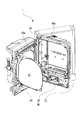
図1に示すように、パチンコ遊技機1は、遊技機枠50と、遊技機枠50内に取り付けられた遊技盤2(図3参照)とを備えている。遊技機枠50は、図1に示すように、パチンコ遊技機1の外郭部を構成するものであり、外枠51と内枠52と前枠(ガラス扉枠)53とを備えている。外枠(基枠部)51は、パチンコ遊技機1の外郭を形成する縦長方形状の枠体である。内枠(保持枠部)52は、外枠51の内側に配置されていて、遊技盤2を取付ける縦長方形状の枠体である。前枠(前扉部)53は、外枠51及び内枠52の前面側に配置されていて、遊技盤2を保護する縦長方形状のものである。   As shown in FIG. 1, the pachinko gaming machine 1 includes a gaming machine frame 50 and a gaming board 2 (see FIG. 3) mounted in the gaming machine frame 50. As shown in FIG. 1, the gaming machine frame 50 constitutes an outer shell of the pachinko gaming machine 1, and includes an outer frame 51, an inner frame 52, and a front frame (glass door frame) 53. The outer frame (base frame portion) 51 is a vertical rectangular frame body that forms the outer shell of the pachinko gaming machine 1. The inner frame (holding frame portion) 52 is a frame body that is arranged inside the outer frame 51 and has a vertically rectangular shape to which the game board 2 is attached. The front frame (front door portion) 53 is arranged on the front side of the outer frame 51 and the inner frame 52, and has a vertical rectangular shape that protects the game board 2.

図2に示すように、遊技機枠50は、左端側にヒンジ部54を備えて構成されている。このヒンジ部54により、前枠53は、外枠51及び内枠52に対してそれぞれ回動自在になっていて、内枠52は、外枠51及び前枠53に対してそれぞれ回動自在になっている。前枠53の中央部には開口部53aが形成されていて、遊技者が後述する遊技領域3を視認できるように透明のガラス板(窓部)55が開口部53aに取付けられている。   As shown in FIG. 2, the gaming machine frame 50 includes a hinge portion 54 on the left end side. By this hinge portion 54, the front frame 53 is rotatable with respect to the outer frame 51 and the inner frame 52, respectively, and the inner frame 52 is rotatable with respect to the outer frame 51 and the front frame 53, respectively. Is becoming An opening 53a is formed in the center of the front frame 53, and a transparent glass plate (window) 55 is attached to the opening 53a so that the player can visually recognize a game area 3 described later.

この遊技機枠50の内枠52には、その内枠52が外枠51に対して開放(回動)していることを検出可能な枠開放検出スイッチ(枠開放検出手段)50aが設けられている。そのため、内枠52が外枠51に対して閉鎖しているときには、枠開放検出スイッチ50aが内枠52の開放を検出していない状態(OFF状態)になる。一方、内枠52が外枠51に対して開放しているときには、枠開放検出スイッチ50aが内枠52の開放を検出している状態(ON状態)になり、検出信号を出力する。以下では、遊技機枠50の開放の検出を説明する際には、内枠52の開放の検出を意味することにする。   The inner frame 52 of the gaming machine frame 50 is provided with a frame opening detection switch (frame opening detection means) 50a capable of detecting that the inner frame 52 is open (rotated) with respect to the outer frame 51. ing. Therefore, when the inner frame 52 is closed with respect to the outer frame 51, the frame opening detection switch 50a does not detect the opening of the inner frame 52 (OFF state). On the other hand, when the inner frame 52 is open with respect to the outer frame 51, the frame opening detection switch 50a is in a state (ON state) in which the opening of the inner frame 52 is detected, and a detection signal is output. In the following, when the detection of the opening of the gaming machine frame 50 is described, it means the detection of the opening of the inner frame 52.

本形態の枠開放スイッチ(枠開放検出手段)50aは、フォトスイッチ(フォトセンサ)である。しかしながら、押しボタンとスプリングとによって物理的な接触を検出するスイッチや、圧力スイッチ(圧力センサ)、近接スイッチ(近接センサ)等であっても良く、適宜変更可能である。なお枠開放検出手段は、内枠52の外枠51に対する開放を検出するものに限られるわけではない。例えば、前枠53の内枠52に対する開放を検出するものであっても良く、内枠52の外枠51に対する開放と、前枠53の内枠52に対する開放の両方を検出できるものであっても良い。また枠開放検出手段の配置箇所は、内枠52に限られるものではなく、外枠51や前枠53であっても良く、適宜変更可能である。   The frame opening switch (frame opening detecting means) 50a of the present embodiment is a photo switch (photo sensor). However, a switch that detects physical contact by a push button and a spring, a pressure switch (pressure sensor), a proximity switch (proximity sensor), or the like may be used and can be appropriately changed. The frame opening detection means is not limited to the one that detects the opening of the inner frame 52 with respect to the outer frame 51. For example, the opening of the front frame 53 to the inner frame 52 may be detected, and both the opening of the inner frame 52 to the outer frame 51 and the opening of the front frame 53 to the inner frame 52 may be detected. Is also good. The location of the frame opening detection means is not limited to the inner frame 52, but may be the outer frame 51 or the front frame 53, and can be changed as appropriate.

図1に示すように、前枠53の右下方側には、回転角度に応じた発射強度で遊技球を発射させるためのハンドル(発射操作手段)60が設けられている。また前枠53の下方側には、遊技球(遊技媒体)を貯留する打球供給皿(上皿)61、及び打球供給皿61に収容しきれない遊技球を貯留する余剰球受皿(下皿)62が設けられている。また打球供給皿61の周辺には、遊技の進行に伴って実行される演出時などに遊技者が操作し得る演出ボタン63やセレクトボタン(十字キー)64が設けられている。なおセレクトボタン64は、上方向ボタンと下方向ボタンと左方向ボタンと右方向ボタンとによって構成されている。   As shown in FIG. 1, on the lower right side of the front frame 53, a handle (launching operation means) 60 for launching a game ball with a launching intensity according to a rotation angle is provided. Further, on the lower side of the front frame 53, a hit ball supply plate (upper plate) 61 for storing game balls (game medium), and a surplus ball receiving plate (lower plate) for storing game balls that cannot be stored in the hit ball supply plate 61. 62 is provided. In addition, around the hitting ball supply plate 61, an effect button 63 and a select button (cross key) 64 which can be operated by the player at the time of effect executed along with the progress of the game are provided. The select button 64 includes an up button, a down button, a left button, and a right button.

次に、図3に基づいて遊技盤2について説明する。図3に示すように、遊技盤2には、ハンドル60の操作により発射された遊技球が流下する遊技領域3が、レール部材4で囲まれて形成されている。また遊技盤2には、装飾用の盤ランプ5(図10参照)が設けられている。なお遊技盤2は、前側に配されている板状部材(遊技板)と、後側に配されている裏ユニット(後述する各種制御基板、画像表示装置7、ハーネス等を取付けるユニット)とが一体化されたものである。   Next, the game board 2 will be described with reference to FIG. As shown in FIG. 3, the game board 2 is formed with a game area 3 surrounded by a rail member 4 in which a game ball shot by operating a handle 60 flows down. The game board 2 is also provided with a decorative board lamp 5 (see FIG. 10). The game board 2 includes a plate-shaped member (game board) arranged on the front side and a back unit (a unit for mounting various control boards, an image display device 7, a harness, etc. described later) arranged on the rear side. It is an integrated one.

遊技領域3には、遊技球の流下する方向に変化を与える複数の遊技くぎが突設されている。また遊技領域3の中央付近には、液晶表示装置である画像表示装置7が配されている。画像表示装置7の表示画面7aには、後述の第1特別図柄および第2特別図柄の可変表示(変動表示)に同期した演出図柄(装飾図柄)8L,8C,8Rの可変表示(変動表示)を行う演出図柄表示領域がある。なお、演出図柄8L,8C,8Rを表示する演出を演出図柄変動演出という。演出図柄変動演出を「装飾図柄変動演出」や単に「変動演出」と称することもある。   The game area 3 is provided with a plurality of game nails that project in the direction in which the game balls flow down. An image display device 7, which is a liquid crystal display device, is arranged near the center of the game area 3. On the display screen 7a of the image display device 7, variable display (variable display) of effect symbols (decorative symbols) 8L, 8C, 8R synchronized with variable display (variable display) of a first special symbol and a second special symbol described later. There is an effect symbol display area for performing. The effect of displaying the effect symbols 8L, 8C, 8R is referred to as effect symbol variation effect. The effect symbol variation effect may be referred to as "decorative symbol variation effect" or simply "variation effect".

演出図柄表示領域は、例えば「左」「中」「右」の3つの図柄表示エリアからなる。左の図柄表示エリアには左演出図柄8Lが表示され、中の図柄表示エリアには中演出図柄8Cが表示され、右の図柄表示エリアには右演出図柄8Rが表示される。演出図柄はそれぞれ、例えば「1」〜「9」までの数字をあらわした複数の図柄からなる。画像表示装置7は、左、中、右の演出図柄の組み合わせによって、後述の第1特別図柄表示器41aおよび第2特別図柄表示器41b(図5参照)にて表示される第1特別図柄および第2特別図柄の可変表示の結果(つまりは大当たり抽選の結果)を、わかりやすく表示する。   The effect symbol display area is composed of, for example, three symbol display areas of "left", "middle", and "right". The left effect design 8L is displayed in the left symbol display area, the middle effect symbol 8C is displayed in the middle symbol display area, and the right effect symbol 8R is displayed in the right symbol display area. Each effect symbol is composed of a plurality of symbols representing numbers "1" to "9", for example. The image display device 7 is a combination of the left, middle, and right effect symbols, and the first special symbol displayed on the first special symbol display 41a and the second special symbol display 41b (see FIG. 5) described above and The result of the variable display of the second special symbol (that is, the result of the jackpot lottery) is displayed in an easy-to-understand manner.

例えば大当たりに当選した場合には「777」などのゾロ目で演出図柄を停止表示する。また、はずれであった場合には「637」などのバラケ目で演出図柄を停止表示する。これにより、遊技者による遊技の進行状況の把握が容易となる。つまり遊技者は、一般的には大当たり抽選の結果を第1特別図柄表示器41aや第2特別図柄表示器41bにより把握するのではなく、画像表示装置7にて把握する。なお、図柄表示エリアの位置は固定的でなくてもよい。また、演出図柄の変動表示の態様としては、例えば上下方向にスクロールする態様がある。   For example, when a big hit is won, the effect symbol is stopped and displayed with a doublet of "777" or the like. In addition, when it is out of alignment, the effect symbol is stopped and displayed with a variation such as "637". This makes it easy for the player to grasp the progress of the game. That is, the player generally grasps the result of the jackpot lottery on the image display device 7, not on the first special symbol display device 41a or the second special symbol display device 41b. The position of the symbol display area does not have to be fixed. In addition, as a mode of variable display of effect symbols, for example, there is a mode of scrolling vertically.

画像表示装置7は、上記のような演出図柄を用いた演出図柄変動演出のほか、大当たり遊技に並行して行われる大当たり演出や、客待ち用のデモ演出(客待ち演出)などを表示画面7aに表示する。なお演出図柄変動演出では、数字等の演出図柄のほか、背景画像やキャラクタ画像などの演出図柄以外の演出画像も表示される。   The image display device 7 displays, in addition to the effect design variation effect using the effect design as described above, a big hit effect performed in parallel with the big hit game, a demonstration effect for waiting for a customer (customer waiting effect), and the like. To display. In the effect design variation effect, in addition to effect patterns such as numbers, effect images other than effect patterns such as background images and character images are also displayed.

また画像表示装置7の表示画面7aには、後述する第1特図保留の記憶数に応じて演出保留画像9Aを表示する第1演出保留表示エリアと、後述する第2特図保留の記憶数に応じて演出保留画像9Bを表示する第2演出保留表示エリアとがある。演出保留画像9A,9Bの表示により、後述の第1特図保留表示器43a(図5参照)にて表示される第1特図保留の記憶数や、第2特図保留表示器43b(図5参照)にて表示される第2特図保留の記憶数を、遊技者にわかりやすく示すことができる。   In addition, on the display screen 7a of the image display device 7, a first effect hold display area for displaying an effect hold image 9A according to the number of first special figure reservations described later, and a number of second special figure reservations described later. There is a second effect hold display area for displaying the effect hold image 9B. Due to the display of the effect holding images 9A and 9B, the number of memories of the first special figure reserved displayed on the later-described first special figure reserved indicator 43a (see FIG. 5) and the second special figure reserved indicator 43b (Fig. The number of stored second special figure reservations displayed in (5) can be easily shown to the player.

遊技領域3の中央付近であって画像表示装置7の前方には、センター装飾体10が配されている。センター装飾体10の下部には、上面を転動する遊技球を、後述の第1始動口20へと誘導可能なステージ部11が形成されている。またセンター装飾体10には、画像表示装置7の表示画面7aよりも前方で移動可能な盤可動体15が設けられている。盤可動体15は初期状態において、図3に示すように前方からほとんど視認できない退避位置にある。そして盤可動体15は、退避位置から表示画面7aの大部分を隠す露出位置(図示省略)へ移動可能になっている。この盤可動体15は、盤可動体駆動モータ15a(図10参照)によって駆動される。   A center ornament 10 is arranged near the center of the game area 3 and in front of the image display device 7. At the lower part of the center ornament 10, a game ball rolling on the upper surface is formed with a stage part 11 capable of guiding the game ball to a first starting opening 20 described later. In addition, the center ornament 10 is provided with a movable board 15 that is movable in front of the display screen 7a of the image display device 7. In the initial state, the movable board 15 is in a retracted position where it is almost invisible from the front as shown in FIG. The movable board 15 can be moved from the retracted position to an exposed position (not shown) that hides most of the display screen 7a. The movable board body 15 is driven by a movable board drive motor 15a (see FIG. 10).

遊技領域3における画像表示装置7の下方には、遊技球の入球し易さが常に変わらない第1始動口(第1入球口や、第1始動入賞口、固定入球口ともいう)20を備える第1始動入賞装置(第1入球手段や固定入球手段ともいう)19が設けられている。第1始動口20への遊技球の入賞は、第1特別図柄の抽選(大当たり抽選、すなわち大当たり乱数等の取得と判定)の契機となっている。   Below the image display device 7 in the game area 3, the first starting opening (also referred to as the first starting winning opening, the first starting winning opening, or the fixed entrance) in which the easiness of entering the game ball is not always changed. A first starting winning device (also referred to as a first ball entering device or a fixed ball entering device) 19 including 20 is provided. The winning of the game ball to the first starting opening 20 is an opportunity for the lottery of the first special symbol (the big hit lottery, that is, the acquisition and the determination of the big hit random numbers and the like).

また遊技領域3における第1始動口20の下方には、第2始動口(第2入球口や、第2始動入賞口、可変入球口ともいう)21を備える普通可変入賞装置(いわゆる電チュー)22が設けられている。電チュー22を、可変入球手段や、第2入球手段、第2始動入賞装置ともいう。第2始動口21への遊技球の入賞は、第2特別図柄の抽選(大当たり抽選)の契機となっている。電チュー22は、開閉部材(可動部材)23を備え、開閉部材23の作動によって第2始動口21を開閉する普通電動役物である。開閉部材23は、電チューソレノイド24(図9参照)により駆動される。開閉部材23が開状態にあるときには、第2始動口21への遊技球の入球が可能となり、閉状態にあるときには、第2始動口21への遊技球の入球が不可能となる。つまり、第2始動口21は、遊技球の入球し易さが変化可能な始動口である。なお、電チューは、開閉部材が開状態にあるときの方が閉状態にあるときよりも第2始動口への入球を容易にするものであれば、閉状態にあるときに第2始動口への入球を不可能とするものでなくてもよい。   Further, below the first starting opening 20 in the game area 3, a normal variable winning device (so-called electric power) having a second starting opening (also referred to as a second entrance opening, a second starting prize opening, or a variable entrance) 21. (Chew) 22 is provided. The electric ball 22 is also referred to as a variable ball entering means, a second ball entering means, and a second starting prize device. The winning of the game ball into the second starting opening 21 is an opportunity for the lottery of the second special symbol (the big hit lottery). The power tube 22 is an ordinary electric accessory that includes an opening/closing member (movable member) 23 and opens/closes the second starting port 21 by the operation of the opening/closing member 23. The opening/closing member 23 is driven by an electric power solenoid 24 (see FIG. 9). When the opening/closing member 23 is in the open state, the game ball can enter the second starting opening 21, and when the opening/closing member 23 is in the closing state, the game ball cannot enter the second starting opening 21. In other words, the second starting opening 21 is a starting opening in which the ease of entering the game ball can be changed. In addition, if the electric chute makes it easier to enter the second starting port when the opening/closing member is in the open state than when the opening/closing member is in the closed state, the second start is performed in the closed state. It does not have to make it impossible to enter the mouth.

また、遊技領域3における第1始動口20の右方には、第1大入賞口(第1特別入賞口)30を備えた第1大入賞装置(第1特別入賞手段や第1特別可変入賞装置ともいう)31が設けられている。第1大入賞装置31は、開状態と閉状態とをとる開閉部材(第1特別入賞口開閉部材)32を備え、開閉部材32の作動により第1大入賞口30を開閉する特別電動役物である。開閉部材32は、第1大入賞口ソレノイド33(図9参照)により駆動される。第1大入賞口30は、開閉部材32が開状態であるときだけ遊技球が入球可能となる。   Further, on the right side of the first start opening 20 in the game area 3, a first big winning device (first special winning means or first special variable winning) having a first big winning opening (first special winning opening) 30. (Also referred to as a device) 31 is provided. The first special winning device 31 includes an opening/closing member (first special winning opening opening/closing member) 32 that opens and closes, and a special electric accessory that opens and closes the first special winning opening 30 by operating the opening/closing member 32. Is. The opening/closing member 32 is driven by the first special winning opening solenoid 33 (see FIG. 9). The first special winning opening 30 can enter the game ball only when the opening/closing member 32 is in the open state.

また、遊技領域3における第1大入賞口30の上方には、第2大入賞口(第2特別入賞口)35を備えた第2大入賞装置(第2特別入賞手段や第2特別可変入賞装置ともいう)36が設けられている。第2大入賞装置36は、開状態と閉状態とをとる開閉部材(第2特別入賞口開閉部材)37を備え、開閉部材37の作動により第2大入賞口35を開閉する特別電動役物である。開閉部材37は、第2大入賞口ソレノイド38(図9参照)により駆動される。第2大入賞口35は、開閉部材37が開状態であるときだけ遊技球が入球可能となる。   Further, above the first special winning opening 30 in the game area 3, a second special winning device (second special winning means or second special variable winning) having a second special winning opening (second special winning opening) 35. 36). The second special winning device 36 includes an opening/closing member (second special winning opening/closing member) 37 that opens and closes, and a special electric accessory that opens and closes the second special winning opening 35 by operating the opening/closing member 37. Is. The opening/closing member 37 is driven by the second special winning opening solenoid 38 (see FIG. 9). The second special winning opening 35 can enter the game ball only when the opening/closing member 37 is in the open state.

また、図4(A),(B)に示すように、第2大入賞装置36の内部には、第2大入賞口35を通過した遊技球が通過可能な特定領域(V領域)39および非特定領域70が形成されている。なお、第2大入賞装置36において、特定領域39および非特定領域70の上流には、第2大入賞口35への遊技球の入賞を検知する第2大入賞口センサ35aが配されている。また、特定領域39には、特定領域39への遊技球の通過を検知する特定領域センサ39aが配されている。また、非特定領域70には、非特定領域70への遊技球の通過を検知する非特定領域センサ70aが配されている。第2大入賞装置36は、第2大入賞口35を通過した遊技球を特定領域39または非特定領域70のいずれかに振り分ける振分部材71と、振分部材71を駆動する振分部材ソレノイド73とを備えている。   As shown in FIGS. 4(A) and 4(B), inside the second special winning device 36, a specific area (V area) 39 through which the game balls that have passed through the second special winning opening 35 can pass, and A non-specific area 70 is formed. In addition, in the second special winning device 36, a second special winning opening sensor 35a for detecting the winning of the game ball into the second special winning opening 35 is arranged upstream of the specific area 39 and the non-specific area 70. .. Further, in the specific area 39, a specific area sensor 39a for detecting passage of a game ball to the specific area 39 is arranged. Further, in the non-specific area 70, a non-specific area sensor 70a for detecting passage of a game ball to the non-specific area 70 is arranged. The second big winning device 36, the distribution member 71 that distributes the game balls that have passed through the second special winning opening 35 to either the specific region 39 or the non-specific region 70, and the distribution member solenoid that drives the distribution member 71. And 73.

図4(A)は、振分部材ソレノイド73の通電時を示している。図4(A)に示すように、振分部材ソレノイド73の通電時には、振分部材71は特定領域39への遊技球の通過を許容する第1の状態(通過許容状態)にある。振分部材71が第1の状態にあるときは、第2大入賞口35に入賞した遊技球は、第2大入賞口センサ35aを通過したあと特定領域39を通過する。この遊技球のルートを第1のルートという。   FIG. 4A shows the distribution member solenoid 73 when energized. As shown in FIG. 4(A), when the distribution member solenoid 73 is energized, the distribution member 71 is in the first state (passage permitted state) in which the game ball is allowed to pass through the specific area 39. When the distribution member 71 is in the first state, the game ball that has won the second special winning opening 35 passes through the specific area 39 after passing through the second special winning opening sensor 35a. The route of this game ball is called the first route.

図4(B)は、振分部材ソレノイド73の非通電時を示している。図4(B)に示すように、振分部材ソレノイド73の非通電時には、振分部材71は特定領域39への遊技球の通過を妨げる第2の状態(通過阻止状態)にある。振分部材71が第2の状態にあるときは、第2大入賞口35に入賞した遊技球は、第2大入賞口センサ35aを通過したあと非特定領域70を通過する。この遊技球のルートを第2のルートという。   FIG. 4B shows the distribution member solenoid 73 when it is not energized. As shown in FIG. 4B, when the distribution member solenoid 73 is not energized, the distribution member 71 is in the second state (passage blocking state) that prevents the game ball from passing to the specific area 39. When the distribution member 71 is in the second state, the game ball winning the second special winning opening 35 passes through the second special winning opening sensor 35a and then passes through the non-specific area 70. The route of this game ball is called the second route.

なお本パチンコ遊技機1では、特定領域39への遊技球の通過が後述の高確率状態への移行の契機となっている。つまり特定領域39は、確変作動口となっている。これに対して非特定領域70は、確変作動口ではない。また、第1大入賞装置31には、確変作動口としての特定領域は設けられていない。すなわち非特定領域しか設けられていない。   In the pachinko gaming machine 1, the passage of the game ball to the specific area 39 serves as a trigger for the transition to the high probability state described later. That is, the specific area 39 is a probability variation operating port. On the other hand, the non-specific area 70 is not the probability variation operating port. In addition, the first special winning device 31 is not provided with a specific area as a probability variation operating port. That is, only the non-specific area is provided.

図3に戻り、遊技領域3における第1大入賞口30の上方には、遊技球が通過可能なゲート(通過口、通過領域ともいう)28が設けられている。ゲート28への遊技球の通過は、電チュー22を開放するか否かを決める普通図柄抽選(すなわち普通図柄乱数(当たり乱数)の取得と判定)の実行契機となっている。さらに遊技領域3の下部には、普通入賞口27が設けられている。また遊技領域3の最下部には、遊技領域3へ打ち込まれたもののいずれの入賞口にも入賞しなかった遊技球を遊技領域3外へ排出するアウト口16が設けられている。   Returning to FIG. 3, above the first special winning opening 30 in the game area 3, there is provided a gate 28 (also called a passage opening or passage area) through which a game ball can pass. The passage of the game ball to the gate 28 is an execution trigger of a normal symbol lottery (that is, acquisition and determination of a normal symbol random number (per random number)) that determines whether to open the electric Chu 22. Further, at the lower part of the game area 3, a normal winning opening 27 is provided. Further, at the bottom of the game area 3, there is provided an outlet 16 for ejecting a game ball that has been hit in the game area 3 but has not won any prize hole to the outside of the game area 3.

このように各種の入賞口等が配されている遊技領域3には、左右方向の中央より左側の左遊技領域(第1遊技領域)3Aと、右側の右遊技領域(第2遊技領域)3Bとがある。左遊技領域3Aを遊技球が流下するように遊技球を発射する打方を、左打ちという。一方、右遊技領域3Bを遊技球が流下するように遊技球を発射する打方を、右打ちという。本形態のパチンコ遊技機1では、左打ちにて遊技したときに遊技球が流下する流路を、第1流路R1といい、右打ちにて遊技したときに遊技球が流下する流路を、第2流路R2という。   In this way, in the game area 3 in which various winning holes and the like are arranged, the left game area (first game area) 3A on the left side of the center in the left-right direction and the right game area (second game area) 3B on the right side. There is. The batting method of launching the game ball so that the game ball flows down the left game area 3A is referred to as left hitting. On the other hand, the batting method of launching the game ball so that the game ball flows down the right game area 3B is called right hitting. In the pachinko gaming machine 1 of the present embodiment, the flow path through which the game ball flows down when playing by left-handing is called the first flow path R1, and the flow path through which the game ball flows down when playing by right-handing. , Second flow path R2.

第1流路R1上には、第1始動口20と、普通入賞口27と、アウト口16とが設けられている。遊技者は第1流路R1を流下するように遊技球を打ち込むことで、第1始動口20や普通入賞口27への入賞を狙うことができる。なお、第1流路R1上にゲート28は配されていない。よって、左打ちをしている場合に電チュー22が開放されることはない。   A first starting opening 20, a normal winning opening 27, and an outlet 16 are provided on the first flow path R1. By hitting the game ball so as to flow down the first flow path R1, the player can aim for winning at the first starting opening 20 and the normal winning opening 27. The gate 28 is not arranged on the first flow path R1. Therefore, the electric tube 22 is not opened when the player is left-handed.

一方、第2流路R2上には、第2大入賞装置36と、ゲート28と、第1大入賞装置31と、電チュー22と、アウト口16とが設けられている。遊技者は第2流路R2を流下するように遊技球を打ち込むことで、ゲート28への通過や、第2大入賞口35、第1大入賞口30、及び第2始動口21への入賞を狙うことができる。   On the other hand, a second big winning device 36, a gate 28, a first big winning device 31, a power tube 22, and an outlet 16 are provided on the second flow path R2. The player hits the game ball so as to flow down the second flow path R2 to pass through the gate 28 and win the second big winning opening 35, the first big winning opening 30, and the second starting opening 21. Can be aimed at.

また遊技盤2の右側には、遊技表示器40が配置されている。遊技表示器40は、後述する遊技制御用マイコン81の制御処理に基づく遊技情報を表示するものである。図5に示すように、遊技表示器40には、第1特別図柄を変動表示する第1特別図柄表示器41aと、第2特別図柄を変動表示する第2特別図柄表示器41bとが含まれている。第1特別図柄表示器41aは、8個の遊技用発光部(LED素子)LA1〜LA8で構成されている。第2特別図柄表示器41bは、8個の遊技用発光部(LED素子)LA9〜LA16で構成されている。   A game display 40 is arranged on the right side of the game board 2. The game display 40 displays game information based on the control processing of the game control microcomputer 81 described later. As shown in FIG. 5, the game display device 40 includes a first special symbol display device 41a that variably displays the first special symbol and a second special symbol display device 41b that variably displays the second special symbol. ing. The first special symbol display device 41a is composed of eight gaming light emitting portions (LED elements) LA1 to LA8. The second special symbol display device 41b is composed of eight gaming light emitting portions (LED elements) LA9 to LA16.

また遊技表示器40には、普通図柄を変動表示する普通図柄表示器42と、第1特別図柄表示器41aの作動保留(第1特図保留)の記憶数を表示する第1特図保留表示器43aと、第2特別図柄表示器41bの作動保留(第2特図保留)の記憶数を表示する第2特図保留表示器43bと、普通図柄表示器42の作動保留(普図保留)の記憶数を表示する普図保留表示器44とが含まれている。普通図柄表示器42は、2個の遊技用発光部(LED素子)LA17,LA18で構成されている。第1特図保留表示器43aは、2個の遊技用発光部(LED素子)LA19,LA20で構成されている。第2特図保留表示器43bは、2個の遊技用発光部(LED素子)LA21,LA22で構成されている。普図保留表示器44は、2個の遊技用発光部(LED素子)LA23,LA24で構成されている。   Further, the game display device 40, the normal symbol display device 42 which displays the normal symbol in a variable manner, and the first special symbol reservation display which displays the number of memories of the operation suspension (first special symbol reservation) of the first special symbol display device 41a. Device 43a, the second special figure hold display 43b that displays the number of memories of the operation hold (second special figure hold) of the second special symbol display 41b, and the operation hold of the normal symbol display 42 (general figure hold) And a universal figure hold indicator 44 for displaying the number of stored items. The normal symbol display 42 is composed of two gaming light emitting parts (LED elements) LA17, LA18. The 1st special figure reservation indicator 43a is formed with two game light-emitting parts (LED elements) LA19, LA20. The second special figure reservation indicator 43b is composed of two game light emitting portions (LED elements) LA21 and LA22. The universal figure reservation indicator 44 is composed of two game light emitting portions (LED elements) LA23 and LA24.

また遊技表示器40には、右打ちすべき状態であることを表示する右打ち表示器45と、現時点での遊技状態を表示する遊技状態表示器46と、大当たり遊技でのラウンド数を表示するラウンド表示器47とが含まれている。右打ち表示器45は、2個の遊技用発光部(LED素子)LA25,LA26で構成されている。遊技状態表示器46は、3個の遊技用発光部(LED素子)LA27〜LA29で構成されている。ラウンド表示器47は、3個の遊技用発光部(LED素子)LA30〜LA32で構成されている。遊技表示器40における合計32個の遊技用発光部LA1〜LA32は、遊技用LED基板40aに実装されている。   Further, the game display device 40 displays a right-handed display device 45 that indicates that the player is in a right-handed state, a game state display device 46 that displays the current game state, and the number of rounds in the jackpot game. A round indicator 47 and is included. The right-handed indicator 45 is composed of two gaming light emitting portions (LED elements) LA25 and LA26. The game status indicator 46 is composed of three gaming light emitting units (LED elements) LA27 to LA29. The round indicator 47 is composed of three gaming light emitting portions (LED elements) LA30 to LA32. A total of 32 gaming light emitting units LA1 to LA32 in the gaming display 40 are mounted on the gaming LED board 40a.

第1特別図柄の変動表示は、第1始動口20への遊技球の入賞を契機として行われる。第2特別図柄の可変表示は、第2始動口21への遊技球の入賞を契機として行われる。なお以下の説明では、第1特別図柄および第2特別図柄を総称して特別図柄ということがある。また、第1特別図柄表示器41aおよび第2特別図柄表示器41bを総称して特別図柄表示器41ということがある。また、第1特図保留および第2特図保留を総称して特図保留ということがある。また、第1特図保留表示器43aおよび第2特図保留表示器43bを総称して特図保留表示器43ということがある。   The variable display of the first special symbol is performed upon the winning of the game ball into the first starting opening 20. The variable display of the second special symbol is triggered by the winning of the game ball into the second starting opening 21. In the following description, the first special symbol and the second special symbol may be collectively referred to as a special symbol. Further, the first special symbol display device 41a and the second special symbol display device 41b may be collectively referred to as the special symbol display device 41. The first special figure hold and the second special figure hold may be collectively referred to as special figure hold. In addition, the first special figure reservation indicator 43a and the second special figure reservation indicator 43b may be collectively referred to as the special figure reservation indicator 43.

特別図柄表示器41では、特別図柄を可変表示(変動表示)したあと停止表示することにより、第1始動口20又は第2始動口21への入賞に基づく抽選(特別図柄抽選、大当たり抽選)の結果を報知する。停止表示される特別図柄(停止図柄、変動表示の表示結果として導出表示される特別図柄)は、特別図柄抽選によって複数種類の特別図柄の中から選択された一つの特別図柄である。停止図柄が予め定めた特定特別図柄(特定の停止態様の特別図柄すなわち大当たり図柄)である場合には、停止表示された大当たり図柄の種類(つまり当選した大当たりの種類)に応じた開放パターンにて大入賞口(第1大入賞口30及び第2大入賞口35)を開放させる大当たり遊技(特別遊技の一例)が行われる。なお、大当たり遊技における大入賞口の開放パターンについては後述する。   In the special symbol display device 41, the special symbol is variably displayed (variable display) and then stopped to display a lottery (special symbol lottery, jackpot lottery) based on the winning of the first starting opening 20 or the second starting opening 21. Notify the result. The special symbol that is stopped and displayed (stop symbol, a special symbol that is derived and displayed as a display result of variable display) is one special symbol that is selected from a plurality of types of special symbols by the special symbol lottery. If the stop symbol is a predetermined special symbol (a special symbol in a specific stop mode, that is, a jackpot symbol), in an open pattern according to the type of jackpot symbol stopped and displayed (that is, the type of jackpot that was won) A jackpot game (an example of a special game) for opening the special winning openings (the first special winning opening 30 and the second special winning opening 35) is performed. The opening pattern of the special winning opening in the jackpot game will be described later.

具体的に第1特別図柄表示器41a又は第2特別図柄表示器41bは、遊技用発光部LA1〜LA8、LA9〜LA16の発光態様によって大当たり抽選の結果に応じた第1特別図柄又は第2特別図柄を表示するものである。例えば第1特別図柄の抽選で大当たり(後述の複数種類の大当たりのうちの一つ)に当選した場合には、第1特別図柄表示器41aで遊技用発光部LA1,LA2,LA5,LA6が発光した大当たり図柄を表示する(図16(A)参照)。また第2特別図柄の抽選でハズレである場合には、第2特別図柄表示器41bで遊技用発光部LA15のみが発光したハズレ図柄を表示する(図16(B)参照)。ハズレ図柄として第1特別図柄表示器41aの全ての遊技用発光部LA1〜LA8や、第2特別図柄表示器41bの全ての遊技用発光部LA9〜LA16を発光しない態様を採用しても良い。なおハズレ図柄は、特定特別図柄ではない。   Specifically, the first special symbol display 41a or the second special symbol display 41b is the first special symbol or the second special symbol according to the result of the jackpot lottery depending on the light emitting mode of the game light emitting units LA1 to LA8 and LA9 to LA16. The pattern is displayed. For example, when the big hit (one of a plurality of kinds of big hits described later) is won in the lottery for the first special symbol, the gaming light emitting portions LA1, LA2, LA5, LA6 emit light on the first special symbol display 41a. The hit jackpot pattern is displayed (see FIG. 16(A)). If the second special symbol is lost in the lottery, the second special symbol display 41b displays the lost symbol emitted only by the game light emitting section LA15 (see FIG. 16(B)). As a lost symbol, all the game light emitting units LA1 to LA8 of the first special symbol display 41a and all the game light emitting units LA9 to LA16 of the second special symbol display 41b may not be emitted. The lost design is not a special special design.

また、特別図柄(第1特別図柄又は第2特別図柄)が停止表示される前には所定の変動時間にわたって特別図柄の変動表示がなされるが、その変動表示の態様は、例えば第1特別図柄表示器41a又は第2特別図柄表示器41bで光が繰り返し流れるように各遊技用発光部LA1〜LA8、LA9〜LA16が発光するという態様である。なお変動表示の態様は、各遊技用発光部LA1〜LA8、LA9〜LA16が停止表示(特定の態様での発光表示)されていなければ、各遊技用発光部LA1〜LA8、LA9〜LA16が一斉に点滅するなどなんでもよい。   Also, before the special symbol (the first special symbol or the second special symbol) is stopped and displayed, the variation display of the special symbol is performed for a predetermined variation time, but the mode of the variation display is, for example, the first special symbol. It is a mode in which each of the gaming light emitting portions LA1 to LA8 and LA9 to LA16 emits light so that light repeatedly flows on the display device 41a or the second special symbol display device 41b. In addition, the mode of the variable display is such that if the gaming light emitting units LA1 to LA8 and LA9 to LA16 are not stopped (light emitting display in a specific mode), the gaming light emitting units LA1 to LA8 and LA9 to LA16 are simultaneously performed. Anything, such as blinking, can be used.

本パチンコ遊技機1では、第1始動口20または第2始動口21への遊技球の入球(入賞)があると、その入球に対して取得した大当たり乱数等の各種乱数の値(入球情報)は、特図保留記憶部85(図9参照)に一旦記憶される。詳細には、第1始動口20への入球であれば第1特図保留として第1特図保留記憶部85a(図9参照)に記憶され、第2始動口21への入球であれば第2特図保留として第2特図保留記憶部85b(図9参照)に記憶される。各々の特図保留記憶部85に記憶可能な特図保留の数には上限があり、本形態における上限値はそれぞれ4個となっている。   In the pachinko gaming machine 1, when a game ball enters the first start opening 20 or the second start opening 21 (prize), various random numbers such as jackpot random numbers (input The sphere information) is temporarily stored in the special figure reservation storage unit 85 (see FIG. 9). Specifically, if the ball enters the first starting opening 20, it is stored in the first special drawing reservation storage unit 85a (see FIG. 9) as the first special drawing reservation, and if it is entering the second starting opening 21. For example, it is stored in the second special figure reservation storage unit 85b (see FIG. 9) as the second special figure reservation. There is an upper limit to the number of special figure reservations that can be stored in each special figure reservation storage unit 85, and the upper limit value in this embodiment is four.

特図保留記憶部85に記憶された特図保留は、その特図保留に基づく特別図柄の可変表示が可能となったときに消化される。特図保留の消化とは、その特図保留に対応する大当たり乱数等を判定して、その判定結果を示すための特別図柄の変動表示を実行することをいう。従って本パチンコ遊技機1では、第1始動口20または第2始動口21への遊技球の入球に基づく特別図柄の変動表示がその入賞後にすぐに行えない場合、すなわち特別図柄の変動表示の実行中や大当たり遊技の実行中に入球があった場合であっても、所定個数を上限として、その入球に対する大当たり抽選の権利を留保することができるようになっている。   The special figure reservation stored in the special figure reservation storage unit 85 is exhausted when the variable display of the special symbol based on the special figure reservation becomes possible. The digestion of the special figure hold means that the jackpot random number or the like corresponding to the special figure hold is determined, and the variable display of the special symbol for indicating the determination result is executed. Therefore, in this pachinko gaming machine 1, when the variable display of the special symbol based on the entry of the game ball into the first starting opening 20 or the second starting opening 21 cannot be performed immediately after the winning, that is, the variable display of the special symbol is displayed. Even if there is a ball entered during the execution or during the jackpot game, the right of the lottery for the entered ball can be reserved with a predetermined number as the upper limit.

そしてこのような特図保留の数は、特図保留表示器43に表示される。例えば第1特図保留表示器43a又は第2特図保留表示器43bは、特図保留(第1特図保留又は第2特図保留)の数が「1」の場合には、右側の遊技用発光部LA19、LA21のみを発光(点灯)させて、特図保留の数が「2」の場合には、左側の遊技用発光部LA20、LA22のみを発光させて、特図保留の数が「3」の場合には、2つの遊技用発光部LA19,LA20、LA21,LA22を点滅させて、特図保留の数が「4」の場合には、2つの遊技用発光部LA19,LA20、LA21,LA22を発光させる。なお本形態では、第2特図保留が第1特図保留よりも優先して消化される。即ち、第2特別図柄の可変表示が第1特別図柄の可変表示よりも優先して実行されるように構成されている。   The number of special figure reservations is displayed on the special figure reservation display 43. For example, the 1st special figure reservation indicator 43a or the 2nd special figure reservation indicator 43b, when the number of special figure reservations (1st special figure reservation or 2nd special figure reservation) is “1”, the game of the right side If only the special light emission units LA19 and LA21 emit light (light up) and the number of special figure reservations is "2", only the left game light emission units LA20 and LA22 emit light to determine the number of special figure reservations. In the case of "3", the two game light emitting units LA19, LA20, LA21, LA22 are made to blink, and in the case of the number of special figure reservations being "4", the two game light emitting units LA19, LA20, The LA21 and LA22 are caused to emit light. In addition, in this embodiment, the second special figure reservation is given priority over the first special figure reservation. That is, the variable display of the second special symbol is configured to be executed with priority over the variable display of the first special symbol.

普通図柄の可変表示は、ゲート28への遊技球の通過を契機として行われる。普通図柄表示器42では、普通図柄を可変表示(変動表示)したあと停止表示することにより、ゲート28への遊技球の通過に基づく普通図柄抽選の結果を報知する。停止表示される普通図柄(普図停止図柄、可変表示の表示結果として導出表示される普通図柄)は、普通図柄抽選によって複数種類の普通図柄の中から選択された一つの普通図柄である。停止表示された普通図柄が予め定めた特定普通図柄(所定の停止態様の普通図柄すなわち普通当たり図柄)である場合には、現在の遊技状態に応じた開放パターンにて第2始動口21を開放させる補助遊技が行われる。なお、第2始動口21の開放パターンについては後述する。   The variable display of the normal symbols is triggered by the passage of the game ball to the gate 28. In the normal symbol display device 42, the normal symbol is variably displayed (variable display) and then stopped to notify the result of the normal symbol lottery based on the passage of the game ball to the gate 28. The normal symbol that is stopped and displayed (ordinary symbol stopped symbol, the ordinary symbol that is derived and displayed as the display result of the variable display) is one ordinary symbol selected from a plurality of ordinary symbols by the ordinary symbol lottery. When the normal symbol displayed in a stopped state is a predetermined specific ordinary symbol (ordinary symbol in a predetermined stop mode, that is, a normal hit symbol), the second starting opening 21 is opened in an opening pattern according to the current game state. Auxiliary game to be performed is performed. The opening pattern of the second starting port 21 will be described later.

具体的に普通図柄表示器42は、遊技用発光部LA17,LA18の発光態様によって普通図柄抽選の結果に応じた普通図柄を表示するものである。例えば抽選結果が当たりである場合には、遊技用発光部LA17,LA18が発光した普通当たり図柄を表示する。また抽選結果がハズレである場合には、下側の遊技用発光部LA17のみが発光した普通ハズレ図柄を表示する(図16(C)参照)。普通ハズレ図柄として遊技用発光部LA17,LA18を発光させない態様を採用してもよい。なお普通ハズレ図柄は、特定普通図柄ではない。普通図柄が停止表示される前には所定の変動時間にわたって普通図柄の変動表示がなされるが、その変動表示の態様は、例えば遊技用発光部LA17,LA18が交互に発光するという態様である。なお変動表示の態様は、遊技用発光部LA17,LA18が停止表示(特定の態様での点灯表示)されていなければ、一斉に点滅するなどなんでもよい。   Specifically, the normal symbol display device 42 displays a normal symbol corresponding to the result of the normal symbol lottery by the light emitting mode of the game light emitting units LA17, LA18. For example, when the lottery result is a win, the normal winning symbols emitted by the game light emitting units LA17 and LA18 are displayed. If the result of the lottery is loss, the normal loss pattern emitted only by the lower game light emitting portion LA17 is displayed (see FIG. 16C). A mode in which the gaming light emitting portions LA17, LA18 are not caused to emit light may be adopted as the normal lost pattern. Note that the normal lost design is not a specific normal design. Before the normal symbol is stopped and displayed, the variable display of the normal symbol is performed for a predetermined fluctuation time, but the mode of the variable display is, for example, a mode in which the gaming light emitting units LA17, LA18 alternately emit light. Note that the mode of variable display may be any mode such as flashing all at once unless the game light emitting units LA17, LA18 are not stopped (displayed in a specific mode).

また本パチンコ遊技機1では、ゲート28への遊技球の通過があると、その通過に対して取得した普通図柄乱数(当たり乱数)の値は、普図保留記憶部86(図9参照)に普図保留として一旦記憶される。普図保留記憶部86に記憶可能な普図保留の数には上限があり、本形態における上限値は4個となっている。   Further, in the pachinko gaming machine 1, when a game ball passes through the gate 28, the value of the normal symbol random number (per random number) acquired for the passage is stored in the universal figure holding storage unit 86 (see FIG. 9). It is temporarily stored as a universal figure reservation. There is an upper limit to the number of universal figure reservations that can be stored in the universal figure reservation storage unit 86, and the upper limit value in this embodiment is four.

普図保留記憶部86に記憶された普図保留は、その普図保留に基づく普通図柄の変動表示が可能となったときに消化される。普図保留の消化とは、その普図保留に対応する普通図柄乱数(当たり乱数)を判定して、その判定結果を示すための普通図柄の変動表示を実行することをいう。従って本パチンコ遊技機1では、ゲート28への遊技球の通過に基づく普通図柄の変動表示がその通過後にすぐに行えない場合、すなわち普通図柄の変動表示の実行中や補助遊技の実行中に入賞があった場合であっても、所定個数を上限として、その通過に対する普通図柄抽選の権利を留保することができるようになっている。   The universal figure hold stored in the universal figure hold storage unit 86 is consumed when the variable display of the ordinary symbol based on the universal figure hold becomes possible. Digesting the universal figure hold means determining a normal symbol random number (per random number) corresponding to the universal figure hold, and executing a variable display of the ordinary symbol to show the determination result. Therefore, in this pachinko gaming machine 1, when the variation display of the normal symbol based on the passage of the game ball to the gate 28 cannot be performed immediately after the passage, that is, the variation display of the ordinary symbol or the execution of the auxiliary game is won. Even if there is, it is possible to reserve the right of the ordinary symbol lottery for the passage with the predetermined number as the upper limit.

そしてこのような普図保留の数は、普図保留表示器44に表示される。例えば普図保留表示器44は、普図保留の数が「1」の場合には、右側の遊技用発光部LA23のみを発光(点灯)させて、普図保留の数が「2」の場合には、左側の遊技用発光部LA24のみを発光させて、普図保留の数が「3」の場合には、2つの遊技用発光部LA23,LA24を点滅させて、普図保留の数が「4」の場合には、2つの遊技用発光部LA23,LA24を発光させる。   The number of such public figure reservations is displayed on the general figure reservation indicator 44. For example, when the number of public figure reservations is "1", the public figure hold indicator 44 causes only the light emitting section LA23 on the right side to emit light (lights), and the number of public figure hold is "2". In the case, the left game light emitting section LA24 is made to emit light, and when the figure holding number is "3", the two game light emitting sections LA23, LA24 are made to blink, and the figure holding number is changed. In the case of "4", the two game light emitting portions LA23 and LA24 are caused to emit light.

また本パチンコ遊技機1では、大当たり遊技が実行されたり、後述するように遊技状態が高確率状態や時短状態に制御され得る。大当たり遊技の実行中(大当たり遊技状態)や、高確率状態又は時短状態では、左打ちよりも右打ちを行った方が遊技者に付与される特典が多くなるため、右打ち表示器45が右打ちすべき状態であることを表示するようになっている。例えば右打ち表示器45は、右打ちすべき状態の表示として、2つの遊技用発光部LA25,LA26を発光させる(図16(D)参照)。なお通常遊技状態では、右打ちよりも左打ちを行った方が遊技者に付与される特典が多くなり易いため、右打ち表示器45は、2つの遊技用発光部LA25,LA26を発光させないようになっている。   Further, in the pachinko gaming machine 1, a jackpot game can be executed, and the gaming state can be controlled to a high probability state or a time saving state as described later. When the big hit game is being executed (big hit game state), in the high probability state or in the short time state, the right-handed indicator 45 is right because the right-handed player has more privileges than the left-handed player. It is designed to display that it is in a state to be hit. For example, the right-handed indicator 45 causes the two gaming light-emitting portions LA25, LA26 to emit light as an indication of the state where the player should right-handed (see FIG. 16D). In the normal game state, the left-handed player is more likely to be given more privileges to the right-handed player than to the right-handed player. Therefore, the right-handed indicator 45 does not cause the two gaming light emitting units LA25 and LA26 to emit light. It has become.

また現時点での遊技状態が、遊技状態表示器46に表示される。例えば高確率状態では、遊技状態表示器46は、2つの遊技用発光部LA27,LA28を発光させる。また時短状態では、遊技状態表示器46は、遊技用発光部LA29を発光させる。従って、高確率状態且つ時短状態では3つの遊技用発光部LA27,LA28,LA29が発光し、通常確率状態且つ時短状態では遊技用発光部LA29のみが発光する。なお通常遊技状態(通常確率状態且つ非時短状態)では、遊技状態表示器46は、3つの遊技用発光部LA27,LA28,LA29を発光させないようになっている(図16(D)参照)。   Further, the current game state is displayed on the game state display 46. For example, in the high probability state, the gaming state indicator 46 causes the two gaming light emitting portions LA27, LA28 to emit light. Further, in the time saving state, the game state indicator 46 causes the game light emitting section LA29 to emit light. Therefore, the three gaming light emitting units LA27, LA28, LA29 emit light in the high probability state and the time saving state, and only the gaming light emitting unit LA29 emits light in the normal probability state and the time saving state. In the normal game state (normal probability state and non-time saving state), the game state indicator 46 does not cause the three game light emitting portions LA27, LA28, LA29 to emit light (see FIG. 16D).

また大当たり遊技でのラウンド数が、ラウンド表示器47に表示される。但し本形態では、大当たり遊技でのラウンド数が16Rのみに設定されている(図37参照)。よってラウンド表示器47は、大当たり遊技の実行中にラウンド数(16R)の表示として、3つの遊技用発光部LA30,LA31,LA32を発光させる(図16(D)参照)。   In addition, the number of rounds in the jackpot game is displayed on the round display 47. However, in this embodiment, the number of rounds in the jackpot game is set to 16R only (see FIG. 37). Therefore, the round display 47 causes the three gaming light emitting portions LA30, LA31, LA32 to emit light as an indication of the number of rounds (16R) during execution of the jackpot game (see FIG. 16D).

ところで本形態のパチンコ遊技機1は、出率を表示することが可能な点に特徴がある。出率(特定割合値)は、電源が投入された時点(所定の開始時点)から遊技者が現時点までに獲得した総賞球数のうち役物(普通電動役物、特別電動役物)の作動に基づいて獲得した賞球数(役物作動賞球数,特定遊技球数)の割合のことである。但し、出率の中には役物比率と連続役物比率とがあって、役物作動賞球数の中には役物賞球数と連続役物賞球数とがある。役物比率は、総賞球数のうち、普通電動役物及び特別電動役物を含む全ての役物の作動に基づいて獲得した賞球数(役物賞球数)の割合である。連続役物比率は、総賞球数のうち、特別電動役物を連続して作動させることに基づいて獲得した賞球数(連続役物賞球数)の割合のことである。つまり連続役物比率は、総賞球数のうち、大当たり遊技の実行のみに基づいて獲得した賞球数の割合のことである。なお総賞球数は、出率を演算する前の分母となる値(分母計測値)であり、役物作動賞球数(役物賞球数、連続役物賞球数)は、出率を演算する前の分子となる値(分子計測値)である。   By the way, the pachinko gaming machine 1 of the present embodiment is characterized in that it is possible to display the percentage. The percentage (specific percentage value) is the number of prizes (normal electric auditors, special electric auditors) out of the total number of prize balls that the player has acquired from the moment the power is turned on (predetermined start time). It is the ratio of the number of prize balls (the number of prize ball operation prize balls, the number of specific game balls) acquired based on the operation. However, there is a character ratio and a continuous character ratio in the proportion, and a number of character prize balls and a number of continuous character prize balls in the number of character operation prize balls. The character ratio is the ratio of the number of prize balls (the number of character prize balls) obtained based on the operation of all characters including the normal electric prize and the special electric prize, out of the total prize balls. The continuous prize ratio is the ratio of the number of prize balls (the number of continuous prize balls) acquired based on the continuous operation of the special electric auditors, out of the total prize balls. That is, the continuous winning character ratio is the ratio of the number of prize balls obtained based on only the execution of the jackpot game to the total number of prize balls. Note that the total number of prize balls is a value (denominator measurement value) that is the denominator before calculating the proportion, and the number of accessory action prize balls (number of prize prize balls, number of consecutive prize balls) is the proportion. Is a value (molecule measurement value) that is a numerator before calculating.

ここでパチンコ遊技機は、ホールに設置される前に、遊技球の試射試験が十時間行われるようになっている。このとき、役物比率が7割(70%)を超えていないことが検査されると共に、連続役物比率が6割(60%)を超えていないことが検査される。つまり、出率が正常範囲内であるか否かが検査される。仮に、役物比率が7割を超えていたり、連続役物比率が6割を超えていれば、遊技者に過剰な特典を付与し得るパチンコ遊技機になっていることになる。こうして、検査で正常範囲内と判断されたパチンコ遊技機がホールに設置されている。しかしながら従来において、検査された後に不正な改造が施されていたり、故障や不具合によって、役物比率が7割を超えていたり、連続役物比率が6割を超えているようなパチンコ遊技機になっている可能性を完全に否定できるものではなかった。   Here, the pachinko game machine is configured such that a test shooting test of a game ball is performed for 10 hours before being installed in a hall. At this time, it is inspected that the duty ratio does not exceed 70% (70%), and that the continuous duty ratio does not exceed 60% (60%). That is, it is inspected whether the output rate is within the normal range. If the duty ratio exceeds 70% or the continuous duty ratio exceeds 60%, it means that the pachinko gaming machine can give an excessive privilege to the player. In this way, pachinko gaming machines that are judged to be within the normal range by inspection are installed in the hall. However, in the past, due to improper modification after inspection, due to breakdowns or defects, the ratio of character roles exceeds 70%, or the ratio of continuous character roles exceeds 60%. It was not possible to completely deny the possibility that it has become.

そこで本形態のパチンコ遊技機1は、不正な改造が施されていたり、故障や不具合が発生しているか否かを判別可能にすべく、出率を表示可能な出率表示器(特定表示器)300を備えている。この出率表示器(表示手段)300は、図6に示すように、主制御基板80の後面側に一体的に取付けられている。主制御基板(主基板)80は、後に詳述するが、遊技の進行に係る制御処理を実行可能な遊技制御用マイコン81を実装した基板である。この遊技制御用マイコン81の制御処理によって、出率表示器300で出率(役物比率又は連続役物比率)の表示が行われる。このように、出率表示器300が主制御基板80上に配されていて、出率の表示が遊技制御用マイコン81によって行われるのは、以下の理由に基づく。   Therefore, in the pachinko gaming machine 1 of the present embodiment, an output ratio display device (specific display device) capable of displaying the output ratio so as to be able to determine whether or not an unauthorized modification has been made, or a failure or malfunction has occurred. ) 300 is provided. This output indicator (display means) 300 is integrally attached to the rear surface side of the main control board 80, as shown in FIG. The main control board (main board) 80, which will be described in detail later, is a board on which a game control microcomputer 81 capable of executing control processing relating to the progress of the game is mounted. By the control processing of the game control microcomputer 81, the output rate display 300 displays the output rate (characteristic ratio or continuous character ratio). In this way, the ratio display 300 is arranged on the main control board 80, and the ratio display is performed by the game control microcomputer 81 for the following reason.

主制御基板80(遊技制御用マイコン81)は、後述するサブ制御基板90等と異なり、試験において適正動作の検査対象になっている。つまり、遊技制御用マイコン81による制御処理は適正であることが保証されるようになっている。従って、遊技制御用マイコン81によって出率の表示が行われるのであれば、出率の表示の信頼性が高い。要するに、出率の表示自体が不正に行われるのを回避するために、出率表示器300を主制御基板80上に配して、出率の表示を遊技制御用マイコン81に行わせている。その結果、出率を確認する人に対して、信頼性のある情報としての出率を把握させることが可能である。   The main control board 80 (game control microcomputer 81) is an inspection target for proper operation in a test, unlike a sub-control board 90, which will be described later. That is, it is ensured that the control processing by the game control microcomputer 81 is proper. Therefore, if the gaming control microcomputer 81 displays the proportion, the reliability of the proportion display is high. In short, in order to prevent the display of the proportion itself from being illegally performed, the proportion display device 300 is arranged on the main control board 80, and the gaming control microcomputer 81 is made to display the proportion. .. As a result, it is possible to make a person who confirms the output rate grasp the output rate as reliable information.

図6に示すように、主制御基板80は、主基板ケース400の内部に収容されている。主基板ケース400は、主制御基板80上の電子部品(集積回路等)の見通しを妨げないように透明な合成樹脂で構成されている。この主基板ケース400は、後方側に配される後方側ケース401と、前方側の前方側ケース402とによって2分割される構造である。主制御基板80の後面側の上方には、コネクタCN2が取付けられている。また図5に示すように、遊技表示器40の遊技用LED基板40aには、コネクタCN1が取付けられている。よって、図示しないハーネスの一端側に取付けられているコネクタが、遊技用LED基板40aのコネクタCN1に接続され、図示しないハーネスの他端側に取付けられているコネクタが、主制御基板80のコネクタCN2に接続される。これにより、遊技制御用マイコン81は、制御処理に基づく信号をハーネスを介して遊技表示器40に出力可能になる。その結果、遊技表示器40は、各遊技用発光部LA1〜LA32を発光させることにより、遊技情報を表示するようになっている。   As shown in FIG. 6, the main control board 80 is housed inside the main board case 400. The main board case 400 is made of transparent synthetic resin so as not to interfere with the visibility of electronic components (such as integrated circuits) on the main control board 80. The main board case 400 has a structure in which it is divided into two by a rear case 401 arranged on the rear side and a front case 402 on the front side. A connector CN2 is attached above the rear surface of the main control board 80. Further, as shown in FIG. 5, a connector CN1 is attached to the game LED board 40a of the game display 40. Therefore, the connector attached to one end side of the harness (not shown) is connected to the connector CN1 of the gaming LED board 40a, and the connector attached to the other end side of the harness (not shown) is the connector CN2 of the main control board 80. Connected to. As a result, the game control microcomputer 81 can output a signal based on the control processing to the game display 40 via the harness. As a result, the game display 40 is adapted to display game information by causing each of the game light emitting units LA1 to LA32 to emit light.

図7に示すように、主制御基板80及び主基板ケース400は、遊技機枠50の裏側に配されている。具体的に、主制御基板80を収容した主基板ケース400は、遊技機枠50の内部にて遊技盤2の裏ユニット(図示省略)の後側に脱着可能に取付けられている。そのため、パチンコ遊技機1がホールに設置されている状態において、遊技機枠50が閉鎖(内枠52が外枠51に対して閉鎖)されていれば、主制御基板80及び出率表示器300を視認することが不可能である。これに対して、遊技機枠50を開放(内枠52を外枠51に対して開放)させれば、透明な後方側ケース401を介して、主制御基板80及び出率表示器300を視認することが可能である。こうして、出率表示器300で表示される出率を確認するためには、遊技機枠50を開放させてから行うようになっている。   As shown in FIG. 7, the main control board 80 and the main board case 400 are arranged on the back side of the gaming machine frame 50. Specifically, the main board case 400 accommodating the main control board 80 is detachably attached to the rear side of the back unit (not shown) of the game board 2 inside the gaming machine frame 50. Therefore, in the state where the pachinko gaming machine 1 is installed in the hall, if the gaming machine frame 50 is closed (the inner frame 52 is closed with respect to the outer frame 51), the main control board 80 and the proportion indicator 300 Is impossible to see. On the other hand, if the gaming machine frame 50 is opened (the inner frame 52 is opened with respect to the outer frame 51), the main control board 80 and the ratio indicator 300 are visually recognized through the transparent rear case 401. It is possible to In this way, in order to confirm the proportion displayed on the proportion display device 300, the gaming machine frame 50 is opened and then performed.

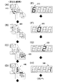
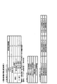
図8に示すように、出率表示器300は、所謂4連7セグであり、遊技表示器40(図5参照)と同様に、合計で32個の点灯(発光)する部分を備えている。具体的に、出率表示器300は、左から右に向かって順番に、第1点灯領域310と第2点灯領域320と第3点灯領域330と第4点灯領域340とを備えている。そして4つの点灯領域(表示領域)310、320、330、340は、それぞれ「0」〜「9」までの数字を表すことができるように、8個の出率用点灯部(LED素子)LB1〜LB8、LB9〜LB16、LB17〜LB24、LB25〜LB32を有している。なお4連7セグは市場に多く流通している流通品であるため、4連7セグを用いることで出率表示器300を安価に構成することが可能である。   As shown in FIG. 8, the proportion indicator 300 is a so-called four-series 7-segment, and like the game indicator 40 (see FIG. 5), is provided with a total of 32 lighted (emitted) portions. .. Specifically, the output indicator 300 includes a first lighting region 310, a second lighting region 320, a third lighting region 330, and a fourth lighting region 340 in order from left to right. The four lighting areas (display areas) 310, 320, 330, and 340 are eight lighting sections (LED elements) LB1 for output ratio so that each of them can represent a number from “0” to “9”. -LB8, LB9-LB16, LB17-LB24, LB25-LB32. Note that since the 4-series 7-segment is a circulation product that is widely distributed in the market, the proportion display device 300 can be inexpensively configured by using the 4-series 7-segment.

次に、出率表示器300での表示について説明する。第1点灯領域310では、出率(役物比率又は連続役物比率)をパーセント(百分率)で表示する場合の十の位の数字を表示することができる。例えば出率が60%である場合には、第1点灯領域310では、出率用点灯部LB1,LB3,LB4,LB5,LB6,LB7が点灯して、「6」を表示する(図26(A)参照)。第2点灯領域320では、出率をパーセント(百分率)で表示する場合の一の位の数字を表示することができる。例えば出率が60%である場合には、第2点灯領域320では、出率用点灯部LB9,LB10,LB11,LB12,LB13,LB14が点灯して、「0」を表示する(図26(B)参照)。   Next, the display on the ratio display 300 will be described. In the first lighting region 310, a tens digit when displaying the output rate (characteristics ratio or continuous character ratio) in percent (percentage) can be displayed. For example, when the proportion is 60%, in the first lighting region 310, the proportion lighting units LB1, LB3, LB4, LB5, LB6, LB7 are lit, and "6" is displayed (Fig. 26 ( See A)). In the second lighting area 320, a digit of ones digit when the output rate is displayed in percent (percentage) can be displayed. For example, when the proportion is 60%, in the second lighting region 320, the proportion lighting units LB9, LB10, LB11, LB12, LB13, and LB14 are lit, and "0" is displayed (Fig. 26 ( See B)).

第3点灯領域330では、第1点灯領域310及び第2点灯領域320で表示している出率が、役物比率又は連続役物比率のどちらであるかを示すようになっている。本形態では、役物比率を表示している場合には、第3点灯領域330で「1」を表示する。つまり、出率用点灯部LB18,LB19が点灯していれば、役物比率を表示していることになる。一方、連続役物比率を表示している場合には、第3点灯領域330で「2」を表示する(図26(C)参照)。つまり、出率用点灯部LB17,LB18,LB20,LB21,LB23が点灯していれば、連続役物比率を表示していることになる。   In the third lighting region 330, the output ratio displayed in the first lighting region 310 and the second lighting region 320 indicates whether the character ratio or the continuous character ratio. In the present embodiment, when the accessory ratio is displayed, “1” is displayed in the third lighting area 330. That is, if the proportion lighting units LB18 and LB19 are lit, it means that the accessory ratio is displayed. On the other hand, when the continuous accessory ratio is displayed, “2” is displayed in the third lighting area 330 (see FIG. 26C). That is, if the proportion lighting units LB17, LB18, LB20, LB21, LB23 are lit, it means that the continuous winning role ratio is displayed.

第4点灯領域340では、第1点灯領域310及び第2点灯領域320で表示している出率が、有効値又は参考値のどちらであるかを示すようになっている。ここで有効値又は参考値の意味について説明する。上述したように、出率は電源が投入された時点から現時点までに獲得した総賞球数のうち役物の作動に基づいて獲得した賞球数の割合であるが、電源が投入された時点から遊技者による遊技が行われた時間が短い場合には、出率が収束していない可能性がある。そのため出率を確認する人にとっては、ある程度収束した値としての出率が表示されていなければ正しく判断できないことになる。   The fourth lighting region 340 is configured to indicate whether the output rate displayed in the first lighting region 310 and the second lighting region 320 is an effective value or a reference value. Here, the meaning of the valid value or the reference value will be described. As described above, the proportion is the ratio of the number of prize balls obtained based on the operation of the winning character to the total number of prize balls acquired from the time the power is turned on to the present time. If the time during which the game is played by the player is short, the output rate may not have converged. Therefore, a person who confirms the participation rate cannot correctly judge unless the distribution rate as a value that converges to some extent is displayed.

そこで本形態では、電源が投入されてから現時点までに獲得した総賞球数が「10000」(所定賞球数)発以上であるという第1条件、又は電源が投入されてから現時点までに特別図柄の変動表示が実行された変動回数が「3000」(所定回転数)回以上であるという第2条件の何れかの条件が満たされていれば、出率がある程度収束した値(有効値)とみなすようにしている。その反対に、上記した第1条件又は第2条件の何れも満たしていなければ、出率がある程度収束していない値(参考値)とみなすようにしている。   Therefore, in this embodiment, the first condition that the total number of prize balls acquired from the time the power is turned on to the present time is “10000” (predetermined number of prize balls) or more, or the special condition from the time the power is turned on to the present time If any of the second conditions that the number of fluctuations in which the variable display of the symbol is executed is “3000” (predetermined number of rotations) or more is satisfied, the value at which the output rate converges to some extent (effective value) I try to regard it as. On the contrary, if neither the above-mentioned first condition nor the above-mentioned second condition is satisfied, it is considered that the output rate has not converged to some extent (reference value).

以上により本形態では、有効値としての出率を表示している場合には、第4点灯領域340で「1」(特定の数字)を表示する(図26(D)参照)。つまり、出率用点灯部LB26,LB27が点灯していれば、上記した第1条件又は第2条件の何れかが満たされていることになる。よって、第4点灯領域340で「1」が表示されていれば、ある程度収束した有効値として出率を正しく判断することが可能である。一方、参考値としての出率を表示する場合には、第4点灯領域340で「0」を表示する。つまり、出率用点灯部LB25,LB26,LB27,LB28,LB29,LB30が点灯していれば、上記した第1条件又は第2条件の何れも満たしていないことになる。よって、第4点灯領域340で「0」が表示されていれば、未だ収束していない可能性がある参考値として出率を確認することが可能である。   As described above, in the present embodiment, when the output rate as the effective value is displayed, “1” (specific number) is displayed in the fourth lighting region 340 (see FIG. 26D). That is, if the output lighting units LB26 and LB27 are lit, it means that either the first condition or the second condition described above is satisfied. Therefore, if "1" is displayed in the fourth lighting region 340, it is possible to correctly determine the output rate as an effective value that has converged to some extent. On the other hand, when displaying the percentage as the reference value, “0” is displayed in the fourth lighting region 340. That is, if the output lighting sections LB25, LB26, LB27, LB28, LB29, and LB30 are lit, none of the above-described first condition or second condition is satisfied. Therefore, if “0” is displayed in the fourth lighting region 340, it is possible to confirm the output ratio as a reference value that may not yet converge.

2.遊技機の電気的構成
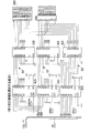
次に図9及び図10に基づいて、本パチンコ遊技機1における電気的な構成を説明する。図9及び図10に示すようにパチンコ遊技機1は、大当たり抽選や遊技状態の移行などの遊技利益に関する制御を行う主制御基板(遊技制御基板)80、遊技の進行に伴って実行する演出に関する制御を行うサブ制御基板(演出制御基板)90、遊技球の払い出しに関する制御を行う払出制御基板110等を備えている。主制御基板80と払出制御基板110はそれぞれ、遊技の結果に影響を及ぼし得る主基板に相当する。主制御基板80と払出制御基板110は、メイン制御部を構成し、サブ制御基板90は、後述する画像制御基板100、サブ駆動基板107、および音声制御基板106とともにサブ制御部を構成する。なお、サブ制御部は、少なくともサブ制御基板90を備え、演出手段(画像表示装置7やスピーカ67、枠ランプ66、盤ランプ5、盤可動体15等)を用いた遊技演出を制御可能であればよい。
2. Electrical Configuration of Gaming Machine Next, the electrical configuration of the pachinko gaming machine 1 will be described with reference to FIGS. 9 and 10. As shown in FIG. 9 and FIG. 10, the pachinko gaming machine 1 relates to a main control board (game control board) 80 that controls the game profit such as a big hit lottery and a transition of the game state, and an effect executed as the game progresses. It is provided with a sub-control board (production control board) 90 for performing control, a payout control board 110 for performing control regarding payout of game balls, and the like. Each of the main control board 80 and the payout control board 110 corresponds to a main board that can influence the result of the game. The main control board 80 and the payout control board 110 form a main control section, and the sub control board 90 forms a sub control section together with an image control board 100, a sub drive board 107, and a voice control board 106, which will be described later. It should be noted that the sub control unit includes at least a sub control board 90, and is capable of controlling the game effect using effect means (image display device 7, speaker 67, frame lamp 66, board lamp 5, board movable body 15, etc.). Good.

またパチンコ遊技機1は、電源基板150を備えている。電源基板150には電源スイッチ155が接続されていて、電源スイッチ155のON/OFF操作により、電源の投入/遮断が切替えられる。なお電源とは、図7に示す電源プラグ160を遊技場(ホール)のコンセントに接続した状態で、電源プラグ160から電源基板150に供給されるAC24Vの電力のことである。電源基板(電源投入手段)150は、AC−DCコンバータやDC−DCコンバータを備え、主制御基板80、サブ制御基板90、及び払出制御基板110の作動に対して必要な電力(DC37V、DC32V、DC12V、DC5V等の電力)を供給可能であると共に、これらの基板を介してその他の機器に対して必要な電力を供給可能である。   The pachinko gaming machine 1 also includes a power supply board 150. A power switch 155 is connected to the power board 150, and turning on/off of the power is switched by turning on/off the power switch 155. Note that the power source means 24V AC power supplied from the power source plug 160 to the power source board 150 in a state where the power source plug 160 shown in FIG. 7 is connected to an outlet of a game hall (hall). The power supply board (power-on means) 150 includes an AC-DC converter and a DC-DC converter, and has power (DC37V, DC32V, DC32V, DC37V, DC32V, etc.) necessary for operating the main control board 80, the sub-control board 90, and the payout control board 110. It is possible to supply electric power (DC 12V, DC 5V, etc.) and to supply necessary electric power to other devices via these substrates.

また電源基板150には、バックアップ電源回路151が設けられている。バックアップ電源回路(バックアップ電源供給手段)151は、営業終了や停電等の電断によって本パチンコ遊技機1に必要な電源が供給されない場合に、後述する主制御基板80のRAM84及び特別メモリ89、サブ制御基板90のRAM94に対して電力を供給することができる。従って、主制御基板80のRAM84及び特別メモリ89、サブ制御基板90のRAM94に記憶されている情報(記憶内容)は、パチンコ遊技機1の電断時であっても保持される。なお主制御基板80のRAM(揮発性メモリ)84及びサブ制御基板90のRAM94は、揮発性の記憶手段(DRAM)である。バックアップ電源回路151は、電解コンデンサのような大容量のコンデンサを備えるものである。なお、主制御基板80のRAM84及び特別メモリ89に対するバックアップ電源回路を主制御基板80に設けたり、サブ制御基板90のRAM94に対するバックアップ電源回路をサブ制御基板90に設けたりしてもよい。   A backup power supply circuit 151 is provided on the power supply board 150. The backup power supply circuit (backup power supply means) 151 is a RAM 84 and a special memory 89 of the main control board 80, a sub memory 89, and a sub memory 89, which will be described later, when the power required for the pachinko gaming machine 1 is not supplied due to power interruption such as business closing or power failure. Power can be supplied to the RAM 94 of the control board 90. Therefore, the information (stored contents) stored in the RAM 84 and the special memory 89 of the main control board 80 and the RAM 94 of the sub control board 90 are retained even when the pachinko gaming machine 1 is powered off. The RAM (volatile memory) 84 of the main control board 80 and the RAM 94 of the sub control board 90 are volatile storage means (DRAM). The backup power supply circuit 151 includes a large-capacity capacitor such as an electrolytic capacitor. A backup power supply circuit for the RAM 84 of the main control board 80 and the special memory 89 may be provided in the main control board 80, or a backup power supply circuit for the RAM 94 of the sub control board 90 may be provided in the sub control board 90.

また電源基板150には、主制御基板80に対してRAM84に記憶されている情報をCPU82にクリアさせるためのRAMクリアスイッチ(RAMクリア操作手段)152が実装されている。図7に示すように主制御基板80が本パチンコ遊技機1の裏側(後面側)に配されている他、電源基板150を含むその他の各種制御基板も本パチンコ遊技機1の裏側に配されている。そのため、遊技機枠50を開放可能なホールの従業員や出率を確認(検査)する人等でなければ、RAMクリアスイッチ152や電源スイッチ155を操作することはできない。すなわち、RAMクリアスイッチ152や電源スイッチ155は、実質的に遊技者による操作が不可能な操作手段といえる。RAMクリアスイッチ152の操作に基づく信号は、電源基板150から主制御基板80に出力される。なおRAMクリアスイッチ152の配置箇所は、電源基板150に限られるものではなく、適宜変更可能であり、例えば主制御基板80であっても良い。   A RAM clear switch (RAM clear operation means) 152 for causing the CPU 82 to clear the information stored in the RAM 84 for the main control board 80 is mounted on the power supply board 150. As shown in FIG. 7, the main control board 80 is arranged on the back side (rear surface side) of the pachinko gaming machine 1, and other various control boards including the power supply board 150 are also arranged on the back side of the pachinko gaming machine 1. ing. Therefore, the RAM clear switch 152 and the power switch 155 can be operated only by an employee in a hall that can open the gaming machine frame 50 or a person who confirms (inspects) the proportion. That is, it can be said that the RAM clear switch 152 and the power switch 155 are operation means that cannot be substantially operated by the player. A signal based on the operation of the RAM clear switch 152 is output from the power supply board 150 to the main control board 80. The location of the RAM clear switch 152 is not limited to the power supply board 150, but can be changed as appropriate, and may be the main control board 80, for example.

図9に示すように、主制御基板80には、プログラムに従ってパチンコ遊技機1の遊技の進行を制御する遊技制御用ワンチップマイコン(以下「遊技制御用マイコン」)81が実装されている。遊技制御用マイコン(主制御手段)81には、遊技の進行を制御するためのプログラム等を記憶したROM83、ROM83に記憶されたプログラムを実行するCPU82、ワークメモリとしてCPU82の処理情報を格納するRAM84、データや信号の入出力を行うためのI/Oポート部(入出力回路)87、及び出率を演算するためのワークメモリとして使用される特別メモリ89が含まれている。   As shown in FIG. 9, on the main control board 80, a game control one-chip microcomputer (hereinafter, “game control microcomputer”) 81 for controlling the progress of the game of the pachinko gaming machine 1 according to a program is mounted. The game control microcomputer (main control means) 81 has a ROM 83 that stores programs for controlling the progress of the game, a CPU 82 that executes the programs stored in the ROM 83, and a RAM 84 that stores processing information of the CPU 82 as a work memory. An I/O port (input/output circuit) 87 for inputting/outputting data and signals, and a special memory 89 used as a work memory for calculating the output rate are included.

RAM84には、図9に示すように、特図保留記憶部85(第1特図保留記憶部85aおよび第2特図保留記憶部85b)と普図保留記憶部86とが設けられている。更にRAM84には、図11(B)に示すように、遊技表示器40に遊技情報を表示するためのデータ情報を記憶する第1遊技データ記憶領域、第2遊技データ記憶領域、第3遊技データ記憶領域、第4遊技データ記憶領域が設けられている。ROM83は外付けであってもよい。   As shown in FIG. 9, the RAM 84 is provided with a special figure reservation storage section 85 (first special figure reservation storage section 85a and second special figure reservation storage section 85b) and a general figure reservation storage section 86. Further, in the RAM 84, as shown in FIG. 11B, a first game data storage area, a second game data storage area, and a third game data that store data information for displaying the game information on the game display 40. A storage area and a fourth game data storage area are provided. The ROM 83 may be externally attached.

特別メモリ(特別記憶手段)89は、出率を演算するための処理情報を格納する専用のメモリである。図11(C)に示すように、特別メモリ89には、100球用カウンタと、実総賞球数カウンタと、役物賞球数カウンタと、連続役物賞球数カウンタと、変動回数カウンタと、役物比率記憶領域と、連続役物比率記憶領域と、チェックサム記憶領域が設けられている。   The special memory (special storage means) 89 is a dedicated memory for storing processing information for calculating the output rate. As shown in FIG. 11C, in the special memory 89, a 100-ball counter, an actual total prize ball number counter, a character prize ball count counter, a continuous character prize ball count counter, and a variation counter. A role ratio storage area, a continuous role ratio storage area, and a checksum storage area are provided.

100球用カウンタ(第1カウンタ)は、遊技者が獲得した賞球数を1球ずつカウントするものであり、100球カウントすると(100球以上のカウントに達すると)「0」の値にリセットされるようになっている。実総賞球数カウンタ(第2カウンタ)は、100球用カウンタにより100球がカウントされると1つカウントするものである。つまり、実総賞球数カウンタは、賞球数が100球に達する度に1つずつ増えていくカウンタである。こうして、100球用カウンタ及び実総賞球数カウンタは、電源が投入された時点から現時点までに払い出された賞球数の合計を百球単位で1つとして計測するもの(百球用計測手段)である。   The 100-ball counter (first counter) counts the number of prize balls acquired by the player, one by one, and resets to a value of "0" when 100 balls are counted (when the number of 100 balls or more is reached). It is supposed to be done. The actual total prize ball number counter (second counter) counts one when 100 balls are counted by the 100-ball counter. That is, the actual total prize ball number counter is a counter that increases by one each time the number of prize balls reaches 100. In this way, the 100-ball counter and the actual total prize ball number counter measure the total number of prize balls paid out from the time the power is turned on until the present time as one hundred-ball unit (one-hundred-ball measurement). Means).

役物賞球数カウンタは、電源が投入された時点から現時点までに役物の作動に基づいて払い出された賞球数の合計を計測するものである。連続役物賞球数カウンタは、電源が投入された時点から大当たり遊技の実行のみに基づいて払い出された賞球数の合計を計測するものである。変動回数カウンタは、電源が投入された時点から現時点までに特別図柄の変動表示が実行された変動回数を計測するものである。役物比率記憶領域は、演算された役物比率を記憶しておくものである。連続役物比率記憶領域は、演算された連続役物比率を記憶しておくものである。チェックサム記憶領域は、後述するように特別メモリ89の記憶内容に関して算出したチェックサムの値を記憶しておくものである。   The prize ball number counter measures the total number of prize balls paid out based on the operation of the accessory from the time when the power is turned on to the present time. The continuous prize prize ball number counter measures the total number of prize balls paid out based on only the execution of the jackpot game from the time the power is turned on. The variation counter is for measuring the number of variations in which the variation display of the special symbol is executed from the time the power is turned on to the present time. The character ratio storage area stores the calculated character ratio. The continuous role ratio storage area stores the calculated continuous role ratio. The checksum storage area stores the value of the checksum calculated for the storage content of the special memory 89 as described later.

本形態では、出率表示器300にて、出率(役物比率又は連続役物比率)を百分率(パーセント)の2桁の整数(例えば「60」)で表示するようになっている。これは仮に、出率を例えば「0.60」のように小数点を用いた表示にすると、整数である「0」と小数点の表示も必要になって、表示する桁数が増えるためである。また3桁以上表示しないのは、出率を確認する人が3桁以上の詳細な値までは把握する必要がほとんどないからである。   In the present embodiment, the output ratio display unit 300 displays the output ratio (characteristic ratio or continuous character ratio) as a two-digit integer (eg, "60") of a percentage (percentage). This is because, if the output rate is displayed using a decimal point such as "0.60", it is necessary to display the integer "0" and the decimal point, and the number of digits to be displayed increases. Also, the reason why the three digits or more is not displayed is that the person who confirms the output rate hardly needs to grasp the detailed values of three digits or more.

ところで、百分率の値としての役物比率を演算しようとする場合、一般的には、役物賞球数に対して1球単位で計測した値である総賞球数で除算した後、100倍する方法が考えられる。しかしながら除算の処理は、「0」で割っていないかを確認したり、桁位置のずれがないかを確認するプログラムが必要であって、四則演算(加算、減算、乗算、除算)の中で負荷が大きい処理である。特に上記した方法の場合では、分母である総賞球数の値が分子である役物賞球数の値よりも大きいことにより、除算の際の桁位置の調整がソフト的に煩雑になる。つまりソフト的に除算の処理では、減算の処理を繰り返し行うことになり、分母の値が分子の値よりも大きいと桁位置の調整によって処理が複雑になる。   By the way, when trying to calculate the character ratio as a percentage value, in general, after dividing the number of character prize balls by the total number of prize balls, which is a value measured in units of 100, 100 times There are possible ways to do it. However, the division process requires a program that confirms whether it is not divided by "0" and whether there is a shift in the digit position, and among the four arithmetic operations (addition, subtraction, multiplication, division) This is a heavy load process. Particularly in the case of the above method, the value of the total number of prize balls, which is the denominator, is larger than the value of the number of accessory prize balls, which is the numerator, so that the adjustment of the digit position at the time of division becomes complicated in terms of software. In other words, in the software division process, the subtraction process is repeated, and if the value of the denominator is larger than the value of the numerator, the process becomes complicated by adjusting the digit position.

そこで本形態では、100球用カウンタ及び実総賞球数カウンタを用いて、総賞球数を百球単位で1つとして計測する。これにより、百分率の値としての役物比率を演算する場合、役物賞球数カウンタの値(役物賞球数)に対して実総賞球数カウンタの値(総賞球数を百球単位で1つとして計測した値)で除算することにしている。その結果、分母の値が分子の値よりも小さくなって、除算の際のソフト的な処理を簡易にすることが可能である。更に、100倍するという乗算の処理を省くことが可能である。   Therefore, in the present embodiment, the total number of prize balls is counted as one in hundreds using the counter for 100 balls and the actual total number of prize balls. Thus, when calculating the character ratio as a percentage value, the value of the actual total prize balls counter (total prize balls is 100 It is decided to divide by one). As a result, the value of the denominator becomes smaller than the value of the numerator, and it is possible to simplify the software processing at the time of division. Furthermore, it is possible to omit the multiplication process of multiplying by 100.

また本形態では上述したように、100球をカウントすると「0」の値にリセット可能な100球用カウンタ(第1カウンタ)と、100球用カウンタによる100球のカウントで1つカウント可能な実総賞球数カウンタ(第2カウンタ)とを用いている。そのため、2バイトの値のまま出率の演算処理を行うことが可能である。即ち、通常のパチンコ遊技機で用いられるカウンタは、2バイトの値(0から65535までの値)をカウント可能なものである。しかしながら、1つのカウンタだけを用いて1球単位で総賞球数をカウントしようとすると、遊技の経過に伴って総賞球数が65535球を超えてしまい、2バイトの値として扱うことができなくなる。よって、100球用カウンタと実総賞球数カウンタという2つのカウンタを用いることにより、実質的に総賞球数を100倍である6553500球までカウントすることが可能である。その結果、出率の演算の上では2バイトの値のまま扱うことが可能である。こうして、遊技制御用マイコン81にとって扱い易い単位(2バイト)のまま出率を演算することが可能であり、演算の処理が複雑になるのを回避することが可能である。   Further, in the present embodiment, as described above, when 100 balls are counted, a 100-ball counter (first counter) that can be reset to a value of “0” and a 100-ball counter that counts 100 balls can count one. A total prize ball number counter (second counter) is used. Therefore, it is possible to perform the calculation processing of the output rate with the value of 2 bytes. That is, the counter used in a normal pachinko gaming machine can count a 2-byte value (value from 0 to 65535). However, if you try to count the total number of prize balls in units of one ball using only one counter, the total number of prize balls exceeds 65535 balls as the game progresses, and it can be treated as a 2-byte value. Disappear. Therefore, by using two counters, that is, a counter for 100 balls and a counter for actual total prize balls, it is possible to substantially count the total prize balls up to 6553500. As a result, it is possible to handle the value of 2 bytes as it is when calculating the output rate. In this way, the output rate can be calculated in a unit (2 bytes) that is easy for the game control microcomputer 81 to handle, and it is possible to prevent the calculation process from becoming complicated.

なお上記では、役物比率を演算する場合に、役物賞球数カウンタの値に対して実総賞球数カウンタの値で除算することについて説明したが、連続役物比率を演算する場合には、連続役物賞球数の値に対して実総賞球数カウンタの値で除算するだけである。従って、上述した作用効果と同様の作用効果を奏することが可能であり、同様の説明を省略する。遊技制御用マイコン81は、演算した役物比率を百分率の値として特別メモリ89の役物比率記憶領域に記憶し、演算した連続役物比率を百分率の値として特別メモリ89の連続役物比率記憶領域に記憶するようになっている。   In the above description, when calculating the character ratio, the value of the character prize ball number counter is divided by the value of the actual total prize ball number counter, but when calculating the continuous character ratio, Is only divided by the value of the actual total prize ball number counter with respect to the value of the number of consecutive prize balls. Therefore, it is possible to achieve the same effect as the above-described effect, and the same description is omitted. The game control microcomputer 81 stores the calculated character ratio as a percentage value in the character ratio storage area of the special memory 89, and stores the calculated continuous character ratio as a percentage value in the continuous character ratio storage of the special memory 89. It is designed to be stored in the area.

ここで本形態では、特別メモリ89に記憶されている情報を、RAM84に記憶されている情報と異なり、電源投入時のRAMクリアスイッチ152の操作によって、消去しないようにしている。つまり、特別メモリ89に記憶されている情報は、本パチンコ遊技機1に対して初めて電源が投入されてから基本的には消去されることがない。従って、本形態において演算される出率(役物比率又は連続役物比率)とは、本パチンコ遊技機1に対して初めて電源が投入されてから現時点までの総賞球数のうち役物作動賞球数(役物賞球数、連続役物賞球数)の割合の意味になる。こうして既存のRAM84とは別に特別メモリ89を設けて、特別メモリ89の記憶内容を消去しないようにしたのは、以下の理由に基づく。   Here, in this embodiment, unlike the information stored in the RAM 84, the information stored in the special memory 89 is not erased by the operation of the RAM clear switch 152 when the power is turned on. That is, the information stored in the special memory 89 is basically not erased after the pachinko gaming machine 1 is powered on for the first time. Therefore, in the present embodiment, the output rate (characteristic ratio or continuous character ratio) is defined as the number of prize balls actuated in the total number of prize balls from the moment the power was first turned on to the pachinko gaming machine 1. It means the ratio of the number of prize balls (number of prize prize balls, number of consecutive prize prize balls). The reason why the special memory 89 is provided separately from the existing RAM 84 so that the stored contents of the special memory 89 are not erased is as follows.

上述したように、出率がある程度収束した値(有効値)になるまでには、遊技者による遊技が十分に行われて、総賞球数及び役物作動賞球数が大きな値になっている必要がある。しかしながら例えば1日経過しても、変動回数が3000回転未満であり且つ総賞球数が10000発未満である場合は十分にあり得る。この場合、翌日に電源投入時のRAMクリアスイッチ152の操作によって、仮に出率を演算するための情報(総賞球数、役物賞球数、連続役物賞球数、変動回数等)がクリアされてしまうと、いつまでも有効値としての出率が算出できないおそれがある。そこで本形態では、電源投入時のRAMクリアスイッチ152の操作でも特別メモリ89の記憶内容を消去しないことにより、有効値としての出率を算出可能にしている。特に、特別メモリ89に記憶されている情報は基本的には消去されることがないため、遊技期間が例えば1か月以上のように長くなれば長くなるほど、より収束した値としての出率を算出することが可能である。   As described above, by the time the participation rate reaches a value that has converged to some extent (effective value), the game is sufficiently played by the player, and the total prize ball number and the accessory working prize ball number become large values. Need to be However, for example, even if one day has passed, it is possible that the number of fluctuations is less than 3000 revolutions and the total number of prize balls is less than 10,000. In this case, the information (total number of prize balls, number of prize prize balls, number of continuous prize prize balls, number of changes, etc.) for temporarily calculating the output rate is obtained by operating the RAM clear switch 152 when the power is turned on the next day. If it is cleared, there is a possibility that the rate as an effective value cannot be calculated forever. Therefore, in the present embodiment, even if the RAM clear switch 152 is operated when the power is turned on, the stored content of the special memory 89 is not erased, so that the output rate as an effective value can be calculated. In particular, since the information stored in the special memory 89 is basically not erased, the longer the game period is, for example, one month or more, the longer the game rate becomes as the value converges. It is possible to calculate.

本形態の特別メモリ89は、電力が供給されなくなると記憶内容を保持することができない揮発性の記憶手段(DRAM)である。しかしながら上述したように、営業終了や停電等の電断が生じているとき、電源基板150のバックアップ電源回路151から特別メモリ89に対して電力(バックアップ電源)を供給可能である。そのため数日程度の電断であれば、特別メモリ89に記憶されている記憶内容が消去されないようになっている。   The special memory 89 of the present embodiment is a volatile storage unit (DRAM) that cannot hold the stored contents when power is cut off. However, as described above, power (backup power supply) can be supplied from the backup power supply circuit 151 of the power supply board 150 to the special memory 89 when power is cut off due to business closing or power failure. Therefore, if the power is cut off for several days, the contents stored in the special memory 89 are not erased.

図9に示す主制御基板80側の電気的な構成の説明に戻る。図9に示すように、主制御基板80には、駆動回路200が設けられている。駆動回路200は、遊技制御用マイコン81から出力される信号(データ情報)に基づいて、遊技表示器40にて遊技情報を表示させるための回路であると共に、出率表示器300にて出率を表示させるための回路である。駆動回路200の構成については、後に詳述する。   Returning to the description of the electrical configuration on the main control board 80 side shown in FIG. As shown in FIG. 9, a drive circuit 200 is provided on the main control board 80. The drive circuit 200 is a circuit for displaying the game information on the game display 40 based on the signal (data information) output from the game control microcomputer 81, and the proportion display 300 Is a circuit for displaying. The configuration of the drive circuit 200 will be described later in detail.

また主制御基板80には、中継基板88を介して各種センサやソレノイドが接続されている。そのため、主制御基板80には各センサから信号が入力され、各ソレノイドには主制御基板80から信号が出力される。具体的にはセンサ類としては、第1始動口センサ20a、第2始動口センサ21a、ゲートセンサ28a、第1大入賞口センサ30a、第2大入賞口センサ35a、特定領域センサ39a、非特定領域センサ70a、および普通入賞口センサ27aが接続されている。更に主制御基板80には、枠開放検出スイッチ50aが接続されていて、枠開放検出スイッチ50aによる検出信号が遊技制御用マイコン81に入力され得る。   Various sensors and solenoids are connected to the main control board 80 via a relay board 88. Therefore, a signal is input from each sensor to the main control board 80, and a signal is output from the main control board 80 to each solenoid. Specifically, the sensors include a first starting opening sensor 20a, a second starting opening sensor 21a, a gate sensor 28a, a first big winning opening sensor 30a, a second big winning opening sensor 35a, a specific area sensor 39a, and a non-specification. The area sensor 70a and the normal winning opening sensor 27a are connected. Further, the frame opening detection switch 50a is connected to the main control board 80, and the detection signal from the frame opening detection switch 50a can be input to the game control microcomputer 81.

第1始動口センサ20aは、第1始動口20内に設けられて、第1始動口20に入賞した遊技球を検出するものである。第2始動口センサ21aは、第2始動口21内に設けられて、第2始動口21に入賞した遊技球を検出するものである。ゲートセンサ28aは、ゲート28内に設けられてゲート28を通過した遊技球を検出するものである。第1大入賞口センサ30aは、第1大入賞口30内に設けられて第1大入賞口30に入賞した遊技球を検出するものである。第2大入賞口センサ35aは、第2大入賞口35内に設けられて第2大入賞口35に入賞した遊技球を検出するものである。特定領域センサ39aは、第2大入賞口35内の特定領域39に設けられて特定領域39を通過した遊技球を検出するものである。非特定領域センサ70aは、第2大入賞口35内の非特定領域70に設けられて非特定領域70を通過した遊技球を検出するものである。普通入賞口センサ27aは、各普通入賞口27内に設けられて普通入賞口27に入賞した遊技球を検出するものである。   The first starting opening sensor 20a is provided in the first starting opening 20 and detects a game ball that has won the first starting opening 20. The second starting port sensor 21a is provided in the second starting port 21 and detects a game ball that has won the second starting port 21. The gate sensor 28a is provided in the gate 28 and detects a game ball that has passed through the gate 28. The first special winning opening sensor 30a is provided in the first special winning opening 30 and detects a game ball that has won the first big winning opening 30. The second special winning opening sensor 35a is provided in the second special winning opening 35 and detects a game ball that has won the second special winning opening 35. The specific area sensor 39a is provided in the specific area 39 inside the second special winning opening 35 and detects a game ball that has passed through the specific area 39. The non-specific area sensor 70a is provided in the non-specific area 70 in the second special winning opening 35 and detects a game ball that has passed through the non-specific area 70. The normal winning opening sensor 27a is provided in each of the normal winning openings 27 and detects a game ball that has won the normal winning opening 27.

またソレノイド類としては、電チューソレノイド24、第1大入賞口ソレノイド33、第2大入賞口ソレノイド38、および振分部材ソレノイド73が接続されている。電チューソレノイド24は、電チュー22の開閉部材23を駆動するものである。第1大入賞口ソレノイド33は、第1大入賞装置31の開閉部材32を駆動するものである。第2大入賞口ソレノイド38は、第2大入賞装置36の開閉部材37を駆動するものである。振分部材ソレノイド73は、第2大入賞装置36の振分部材71を駆動するものである。   Further, as solenoids, an electric power solenoid 24, a first special winning opening solenoid 33, a second special winning opening solenoid 38, and a distribution member solenoid 73 are connected. The electric Chu solenoid 24 drives the opening/closing member 23 of the electric Chu 22. The first special winning opening solenoid 33 drives the opening/closing member 32 of the first special winning device 31. The second special winning opening solenoid 38 drives the opening/closing member 37 of the second special winning device 36. The distribution member solenoid 73 drives the distribution member 71 of the second big winning device 36.

さらに主制御基板80には、遊技表示器40(第1特別図柄表示器41a、第2特別図柄表示器41b、普通図柄表示器42、第1特図保留表示器43a、第2特図保留表示器43b、普図保留表示器44、右打ち表示器45、遊技状態表示器46、ラウンド表示器47)が接続されている。また主制御基板80は、払出制御基板110に各種コマンドを送信するとともに、払い出し監視のために払出制御基板110から信号を受信する。   Further, on the main control board 80, the game display 40 (first special symbol display 41a, second special symbol display 41b, normal symbol display 42, first special symbol reservation display 43a, second special symbol reservation display The device 43b, the universal figure reservation display 44, the right hitting display 45, the game state display 46, and the round display 47) are connected. Further, the main control board 80 sends various commands to the payout control board 110 and receives signals from the payout control board 110 for payout monitoring.

払出制御基板110には、賞球払出装置120、貸球払出装置130およびカードユニット135(パチンコ遊技機1に隣接して設置され、挿入されているプリペイドカード等の情報に基づいて球貸しを可能にするもの)が接続されているとともに、発射制御回路111を介して発射装置112が接続されている。発射装置112には、ハンドル60(図1参照)が含まれる。なお払出制御基板110は、図7に示すように、主制御基板80よりも下方に配されていて、透明の合成樹脂で構成された払出基板ケース500に囲われている。   On the payout control board 110, a prize ball payout device 120, a ball rental payout device 130, and a card unit 135 (installed adjacent to the pachinko gaming machine 1 and capable of lending a ball based on information of a prepaid card or the like inserted therein) (Not shown) is connected, and the launch device 112 is also connected via the launch control circuit 111. The firing device 112 includes a handle 60 (see FIG. 1). As shown in FIG. 7, the payout control board 110 is arranged below the main control board 80 and is surrounded by a payout board case 500 made of transparent synthetic resin.

払出制御基板(主基板)110は、プログラムに従って遊技球の払い出しに係る制御処理を実行可能な払出制御用ワンチップマイコン(以下「払出制御用マイコン」)116を実装している。払出制御用マイコン(払出制御手段)116には、払い出しを制御するためのプログラムを記憶したROM118、ワークメモリとして使用されるRAM119、ROM118に記憶されたプログラムを実行するCPU117、データや信号の入出力を行うためのI/Oポート部(入出力回路)109が含まれている。なお、ROM118は外付けであってもよい。   The payout control board (main board) 110 is equipped with a payout control one-chip microcomputer (hereinafter, “payout control microcomputer”) 116 capable of executing control processing related to payout of game balls according to a program. The payout control microcomputer (payout control means) 116 includes a ROM 118 storing a program for controlling payout, a RAM 119 used as a work memory, a CPU 117 for executing the program stored in the ROM 118, and input/output of data and signals. An I/O port unit (input/output circuit) 109 for performing the above is included. The ROM 118 may be externally attached.

払出制御用マイコン116は、遊技制御用マイコン81からの信号(賞球コマンド)に基づいて、賞球払出装置120の賞球モータ121を駆動して賞球の払い出しを行う。払い出される賞球は、その計数のため賞球センサ122により検出され、賞球センサ122による検出信号が払出制御基板110に出力される。本形態では、普通入賞口27への入賞による賞球数は8球である。また、第1始動口20への入賞による賞球数は3球であり、第2始動口21への入賞による賞球数は7球である。そして、第1大入賞口30への入賞による賞球数は15球であり、第2大入賞口35への入賞による賞球数は15球である(図11(A)参照)。なお各入賞口への入賞による賞球数は、上記したものに限られず、適宜変更可能である。   The payout control microcomputer 116 drives the prize ball motor 121 of the prize ball payout device 120 based on a signal (prize ball command) from the game control microcomputer 81 to pay out prize balls. The prize balls to be paid out are detected by the prize ball sensor 122 for counting, and a detection signal from the prize ball sensor 122 is output to the payout control board 110. In the present embodiment, the number of prize balls due to the winning in the normal winning opening 27 is eight. Further, the number of prize balls due to winning in the first starting port 20 is 3 and the number of prize balls due to winning in the second starting port 21 is 7. Then, the number of prize balls due to winning in the first major winning opening 30 is 15, and the number of prize balls due to winning in the second major winning opening 35 is 15 (see FIG. 11A). The number of prize balls to be won in each prize hole is not limited to the above number and can be changed as appropriate.

また払出制御用マイコン116は、パチンコ遊技機1に接続されたカードユニット135からの信号に基づいて、貸球払出装置130の球貸モータ131を駆動して貸球の払い出しを行う。払い出される貸球は、その計数のため球貸センサ132により検出され、球貸センサ132による検出信号が払出制御基板110に出力される。なお遊技者による発射装置112のハンドル60(図1参照)への操作があった場合には、タッチスイッチ114がハンドル60への接触を検知し、発射ボリューム115がハンドル60の回転量を検知する。そして、発射ボリューム115の検知信号の大きさに応じた強さで遊技球が発射されるよう発射モータ113が駆動されることとなる。本パチンコ遊技機1においては、0.6秒程度で一発の遊技球が発射されるようになっている。   Further, the payout control microcomputer 116 drives the ball lending motor 131 of the ball lending device 130 based on a signal from the card unit 135 connected to the pachinko gaming machine 1 to pay out the ball. The balls to be paid out are detected by the ball lending sensor 132 for counting, and a detection signal from the ball lending sensor 132 is output to the payout control board 110. When the player operates the handle 60 (see FIG. 1) of the firing device 112, the touch switch 114 detects contact with the handle 60, and the firing volume 115 detects the rotation amount of the handle 60. .. Then, the launch motor 113 is driven so that the game ball is launched with a strength corresponding to the magnitude of the detection signal of the launch volume 115. In the pachinko gaming machine 1, one game ball is shot in about 0.6 seconds.

また主制御基板80は、サブ制御基板90に対し各種コマンドを送信する。主制御基板80とサブ制御基板90との接続は、主制御基板80からサブ制御基板90への信号の送信のみが可能な単方向通信接続となっている。すなわち、主制御基板80とサブ制御基板90との間には、通信方向規制手段としての図示しない単方向性回路(例えばダイオードを用いた回路)が介在している。   Further, the main control board 80 transmits various commands to the sub control board 90. The connection between the main control board 80 and the sub control board 90 is a unidirectional communication connection in which only signals can be transmitted from the main control board 80 to the sub control board 90. That is, between the main control board 80 and the sub control board 90, a unidirectional circuit (for example, a circuit using a diode) (not shown) serving as a communication direction restricting means is interposed.

図10に示すように、サブ制御基板90には、プログラムに従ってパチンコ遊技機1の演出を制御する演出制御用ワンチップマイコン(以下「演出制御用マイコン」)91が実装されている。演出制御用マイコン(演出制御手段)91には、遊技の進行に伴って演出を制御するためのプログラム等を記憶したROM93、ワークメモリとして使用されるRAM94、ROM93に記憶されたプログラムを実行するCPU92、データや信号の入出力を行うためのI/Oポート部(入出力回路)97が含まれている。なお、ROM93は外付けであってもよい。   As shown in FIG. 10, on the sub-control board 90, a one-chip microcomputer for effect control (hereinafter referred to as “effect control microcomputer”) 91 for controlling the effect of the pachinko game machine 1 according to a program is mounted. In the effect control microcomputer (effect control means) 91, a ROM 93 storing a program for controlling the effect as the game progresses, a RAM 94 used as a work memory, and a CPU 92 executing the program stored in the ROM 93. , An I/O port unit (input/output circuit) 97 for inputting/outputting data and signals. The ROM 93 may be externally attached.

サブ制御基板90には、画像制御基板100、音声制御基板106、サブ駆動基板107が接続されている。サブ制御基板90の演出制御用マイコン91は、主制御基板80から受信したコマンドに基づいて、画像制御基板100のCPU102に画像表示装置7の制御を行わせる。   An image control board 100, a sound control board 106, and a sub drive board 107 are connected to the sub control board 90. The effect control microcomputer 91 of the sub control board 90 causes the CPU 102 of the image control board 100 to control the image display device 7 based on the command received from the main control board 80.

画像制御基板100は、画像表示等の制御のためのプログラム等を記憶したROM103、ワークメモリとして使用されるRAM104、及びROM103に記憶されたプログラムを実行するCPU102を備えている。なお、ROM103には、画像表示装置7に表示される静止画データや動画データ、具体的にはキャラクタ、アイテム、図形、文字、数字および記号等(演出図柄を含む)や背景画像等の画像データが格納されている。   The image control board 100 includes a ROM 103 that stores a program for controlling image display and the like, a RAM 104 that is used as a work memory, and a CPU 102 that executes the program stored in the ROM 103. The ROM 103 stores still image data and moving image data displayed on the image display device 7, specifically, image data such as characters, items, figures, characters, numbers and symbols (including effect patterns) and background images. Is stored.

また演出制御用マイコン91は、主制御基板80から受信したコマンドに基づいて、音声制御基板106を介してスピーカ67から音声、楽曲、効果音等を出力する。スピーカ67から出力する音声等の音響データは、サブ制御基板90のROM93に格納されている。なお、音声制御基板106にCPUを実装してもよく、その場合、そのCPUに音声制御を実行させてもよい。さらにこの場合、音声制御基板106にROMを実装してもよく、そのROMに音響データを格納してもよい。また、スピーカ67を画像制御基板100に接続し、画像制御基板100のCPU102に音声制御を実行させてもよい。さらにこの場合、画像制御基板100のROM103に音響データを格納してもよい。   In addition, the effect control microcomputer 91 outputs a voice, a song, a sound effect, etc. from the speaker 67 via the voice control board 106 based on the command received from the main control board 80. Acoustic data such as voice output from the speaker 67 is stored in the ROM 93 of the sub control board 90. A CPU may be mounted on the voice control board 106, and in that case, the CPU may be caused to execute voice control. Further, in this case, a ROM may be mounted on the voice control board 106, and the acoustic data may be stored in the ROM. Alternatively, the speaker 67 may be connected to the image control board 100, and the CPU 102 of the image control board 100 may be caused to execute voice control. Further, in this case, the acoustic data may be stored in the ROM 103 of the image control board 100.

また演出制御用マイコン91は、主制御基板80から受信したコマンドに基づいて、サブ駆動基板107及び中継基板108を介して、枠ランプ66(遊技機枠50に設けられている発光手段)や盤ランプ5等のランプの点灯制御を行う。詳細には演出制御用マイコン91は、各ランプ(LED素子)の発光態様を決める発光パターンデータ(点灯/消灯や発光色等を決めるデータ、ランプデータともいう)を作成し、発光パターンデータに従って各ランプ(LED素子)の発光を制御する。なお、発光パターンデータの作成にはサブ制御基板90のROM93に格納されているデータを用いる。   Further, the effect control microcomputer 91, in accordance with the command received from the main control board 80, via the sub drive board 107 and the relay board 108, a frame lamp 66 (light emitting means provided in the gaming machine frame 50) and a board. Lighting control of the lamps such as the lamp 5 is performed. Specifically, the production control microcomputer 91 creates light emission pattern data (data for determining lighting/extinguishment, light emission color, etc., lamp data) that determines the light emission mode of each lamp (LED element), and according to each light emission pattern data. It controls the light emission of the lamp (LED element). Note that the data stored in the ROM 93 of the sub control board 90 is used to create the light emission pattern data.

さらに演出制御用マイコン91は、主制御基板80から受信したコマンドに基づいて、サブ駆動基板107及び中継基板108を介して盤可動体15の駆動制御を行う。詳細には演出制御用マイコン91は、盤可動体15の動作態様を決める動作パターンデータ(駆動データともいう)を作成し、動作パターンデータに従って盤可動体駆動モータ15aの駆動制御を行う。動作パターンデータの作成にはサブ制御基板90のROM93に格納されているデータを用いる。   Further, the effect control microcomputer 91 performs drive control of the movable board 15 via the sub drive board 107 and the relay board 108 based on the command received from the main control board 80. Specifically, the effect control microcomputer 91 creates operation pattern data (also referred to as drive data) that determines the operation mode of the movable board 15, and controls the driving of the movable body drive motor 15a according to the operation pattern data. The data stored in the ROM 93 of the sub control board 90 is used to create the operation pattern data.

またサブ制御基板90には、演出ボタン検出スイッチ(SW)63a及びセレクトボタン検出スイッチ64aが接続されている。演出ボタン検出スイッチ63aは、演出ボタン63(図1参照)が押下操作されたことを検出するものである。演出ボタン63が押下操作されると演出ボタン検出スイッチ63aからサブ制御基板90に対して検知信号が出力される。また、セレクトボタン検出スイッチ64aは、セレクトボタン64(図1参照)が押下操作されたことを検出するものである。セレクトボタン64が押下操作されるとセレクトボタン検出スイッチ64aからサブ制御基板90に対して検知信号が出力される。   The sub-control board 90 is also connected to a production button detection switch (SW) 63a and a select button detection switch 64a. The effect button detection switch 63a is for detecting that the effect button 63 (see FIG. 1) has been pressed. When the effect button 63 is pressed, a detection signal is output from the effect button detection switch 63a to the sub control board 90. The select button detection switch 64a detects that the select button 64 (see FIG. 1) has been pressed. When the select button 64 is pressed, the select button detection switch 64a outputs a detection signal to the sub control board 90.

なお図9及び図10は、あくまで本パチンコ遊技機1における電気的な構成を説明するための機能ブロック図であり、図9及び図10に示す基板だけが設けられているわけではない。主制御基板80を除いて、図9又は図10に示す何れか複数の基板を1つの基板として構成しても良く、図9又は図10に示す1つの基板を複数の基板として構成しても良い。   9 and 10 are merely functional block diagrams for explaining the electrical configuration of the pachinko gaming machine 1, and not only the boards shown in FIGS. 9 and 10 are provided. Except for the main control board 80, any of a plurality of boards shown in FIG. 9 or 10 may be configured as one board, or one board shown in FIG. 9 or 10 may be configured as a plurality of boards. good.

3.遊技表示器40及び出率表示器300と遊技制御用マイコン81との接続状態
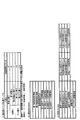
次に、遊技表示器40及び出率表示器300と遊技制御用マイコン81との接続状態について、図12〜図15に基づいて説明する。そこで先ず、図12に基づいて、遊技表示器40の各遊技用発光部(発光部)LA1〜LA32の電気的な接続状態について説明する。図12に示すように、遊技表示器40に設けられているコネクタCN1には、12個のピンが設けられている。
3. Connection state between the game display 40 and the ratio display 300 and the game control microcomputer 81 Next, regarding the connection between the game display 40 and the ratio display 300 and the game control microcomputer 81, FIGS. It will be explained based on. Then, first, based on FIG. 12, an electrical connection state of each of the gaming light emitting portions (light emitting portions) LA1 to LA32 of the gaming display 40 will be described. As shown in FIG. 12, the connector CN1 provided in the game display 40 is provided with 12 pins.

コネクタCN1の1番ピンから4番ピンまでには、第1コモン信号ラインA1、第2コモン信号ラインA2、第3コモン信号ラインA3、第4コモン信号ラインA4がそれぞれつながっている。コネクタCN1の5番ピンから12番ピンまでには、第1データ信号ラインAa、第2データ信号ラインAb、第3データ信号ラインAc、第4データ信号ラインAd、第5データ信号ラインAe、第6データ信号ラインAf、第7データ信号ラインAg、第8データ信号ラインAhがそれぞれつながっている。   The first common signal line A1, the second common signal line A2, the third common signal line A3, and the fourth common signal line A4 are connected to pins 1 to 4 of the connector CN1. From the 5th pin to the 12th pin of the connector CN1, the first data signal line Aa, the second data signal line Ab, the third data signal line Ac, the fourth data signal line Ad, the fifth data signal line Ae, the The sixth data signal line Af, the seventh data signal line Ag, and the eighth data signal line Ah are connected to each other.

なお以下では、第1特別図柄表示器41aの各遊技用発光部LA1〜LA8が設けられている領域を、「第1発光領域410」と呼ぶことにする。また第2特別図柄表示器41bの各遊技用発光部LA9〜LA16が設けられている領域を、「第2発光領域420」と呼ぶことにする。また、普通図柄表示器42の各遊技用発光部LA17,LA18と、特図保留表示器43の各遊技用発光部LA19〜LA22と、普図保留表示器44の各遊技用発光部LA23,LA24とが設けられている領域を、「第3発光領域430」と呼ぶことにする。また、右打ち表示器45の各遊技用発光部LA25,LA26と、遊技状態表示器46の各遊技用発光部LA27〜LA29と、ラウンド表示器47の各遊技用発光部LA30〜LA32とが設けられている領域を、「第4発光領域440」と呼ぶことにする。   In the following, the area where the gaming light emitting portions LA1 to LA8 of the first special symbol display device 41a are provided is referred to as a "first light emitting area 410". Moreover, the area|region where each game light-emitting part LA9-LA16 of the 2nd special symbol display 41b is provided is called "the 2nd light-emitting area 420." In addition, each game light emitting section LA17, LA18 of the normal symbol display 42, each game light emitting section LA19-LA22 of the special figure reservation display 43, and each game light emitting section LA23, LA24 of the general figure reservation display 44. The region where and are provided will be referred to as a “third light emitting region 430”. In addition, the gaming light emitting portions LA25 and LA26 of the right-handed indicator 45, the gaming light emitting portions LA27 to LA29 of the gaming state indicator 46, and the gaming light emitting portions LA30 to LA32 of the round indicator 47 are provided. The area provided is referred to as a “fourth light emitting area 440”.

第1コモン信号ラインA1は、第1発光領域410の各遊技用発光部LA1〜LA8につながっている。第2コモン信号ラインA2は、第2発光領域420の各遊技用発光部LA9〜LA16につながっている。第3コモン信号ラインA3は、第3発光領域430の各遊技用発光部LA17〜LA24につながっている。第4コモン信号ラインA4は、第4発光領域440の各遊技用発光部LA25〜LA32につながっている。そして、第1データ信号ラインAaから第8データ信号ラインAhまでの8個のデータ信号ラインAa〜Ahは、第1発光領域410の8個の遊技用発光部LA1〜LA8と、第2発光領域420の8個の遊技用発光部LA9〜LA16と、第3発光領域430の8個の遊技用発光部LA17〜LA24と、第4発光領域440の8個の遊技用発光部LA25〜LA32にそれぞれつながっている。   The first common signal line A1 is connected to the gaming light emitting portions LA1 to LA8 of the first light emitting area 410. The second common signal line A2 is connected to the gaming light emitting portions LA9 to LA16 in the second light emitting area 420. The third common signal line A3 is connected to the gaming light emitting portions LA17 to LA24 in the third light emitting area 430. The fourth common signal line A4 is connected to the gaming light emitting portions LA25 to LA32 in the fourth light emitting region 440. The eight data signal lines Aa to Ah from the first data signal line Aa to the eighth data signal line Ah are the eight game light emitting portions LA1 to LA8 of the first light emitting area 410 and the second light emitting area. Eight 420 game light emitting units LA9 to LA16, eight game light emitting units LA17 to LA24 in the third light emitting region 430, and eight game light emitting units LA25 to LA32 in the fourth light emitting region 440, respectively. linked.

上述した接続により、遊技制御用マイコン81は、32個の遊技用発光部LA1〜LA32に対してダイナミック点灯制御を行うことになる。即ち、仮に32個の遊技用発光部LA1〜LA32に対してそれぞれ1つずつ(合計32個の)信号ラインを接続して、スタティック点灯制御を行うと、信号ラインの数が多くなり過ぎて、8ビットマイコンである遊技制御用マイコン81では、点灯制御することができない。よって、8個の遊技用発光部を有する発光領域410,420,430,440毎に、それぞれコモン信号ラインA1,A2,A3,A4を接続することで、信号ラインの数を減らすようにしている。その上で、本形態では4ms毎に、4つの発光領域410,420,430,440のうち発光させ得る発光領域を順次切替える。これにより、残像現象を利用して、人間の目には4つの発光領域410,420,430,440で同時に発光しているように見せることが可能である。   By the connection described above, the game control microcomputer 81 will perform dynamic lighting control for the 32 game light emitting units LA1 to LA32. That is, if one signal line (32 in total) is connected to each of the 32 game light emitting units LA1 to LA32 and static lighting control is performed, the number of signal lines becomes too large. The game control microcomputer 81, which is an 8-bit microcomputer, cannot control lighting. Therefore, the number of signal lines is reduced by connecting the common signal lines A1, A2, A3, A4 to each of the light emitting areas 410, 420, 430, 440 having the eight game light emitting portions. .. Then, in the present embodiment, the light emitting regions capable of emitting light among the four light emitting regions 410, 420, 430, 440 are sequentially switched every 4 ms. Thus, by utilizing the afterimage phenomenon, it is possible for the human eye to appear to simultaneously emit light in the four light emitting regions 410, 420, 430, 440.

ダイナミック点灯制御の概要について説明する。例えば、32個の全ての遊技用発光部LA1〜LA32が発光しているように見せることにする。この場合には、先ず第1コモン信号ラインA1の電圧を「H」レベル(上限閾値電圧よりも高い電圧)にして、その他のコモン信号ラインA2,A3,A4の電圧を「L」レベル(下限閾値電圧よりも低い電圧)にする。そして、各データ信号ラインAa〜Ahの電圧を「H」レベルにする。これにより、第1発光領域410にある全ての遊技用発光部LA1〜LA8に駆動電流が流れて、遊技用発光部LA1〜LA8が発光する。続いて4ms後に、第2コモン信号ラインA2の電圧を「H」レベルにして、その他のコモン信号ラインA1,A3,A4の電圧を「L」レベルにする。そして、各データ信号ラインAa〜Ahの電圧を「H」レベルにする。これにより、第2発光領域420にある全ての遊技用発光部LA9〜LA16に駆動電流が流れて、遊技用発光部LA9〜LA16が発光する。   The outline of the dynamic lighting control will be described. For example, all of the 32 game light emitting units LA1 to LA32 are made to appear to be emitting light. In this case, first, the voltage of the first common signal line A1 is set to the “H” level (voltage higher than the upper limit threshold voltage), and the voltages of the other common signal lines A2, A3, A4 are set to the “L” level (lower limit). Voltage lower than the threshold voltage). Then, the voltage of each data signal line Aa-Ah is set to the “H” level. As a result, a driving current flows through all the gaming light emitting portions LA1 to LA8 in the first light emitting area 410, and the gaming light emitting portions LA1 to LA8 emit light. Then, 4 ms later, the voltage of the second common signal line A2 is set to "H" level, and the voltages of the other common signal lines A1, A3, A4 are set to "L" level. Then, the voltage of each data signal line Aa-Ah is set to the “H” level. As a result, a driving current flows through all the gaming light emitting portions LA9 to LA16 in the second light emitting area 420, and the gaming light emitting portions LA9 to LA16 emit light.

続いて4ms後に、第3コモン信号ラインA3の電圧を「H」レベルにして、その他のコモン信号ラインA1,A2,A4の電圧を「L」レベルにする。そして、各データ信号ラインAa〜Ahの電圧を「H」レベルにする。これにより、第3発光領域430にある全ての遊技用発光部LA17〜LA24に駆動電流が流れて、遊技用発光部LA17〜LA24が発光する。続いて4ms後に、第4コモン信号ラインA4の電圧を「H」レベルにして、その他のコモン信号ラインA1,A2,A3の電圧を「L」レベルにする。そして、各データ信号ラインAa〜Ahの電圧を「H」レベルにする。これにより、第4発光領域440にある全ての遊技用発光部LA25〜LA32に駆動電流が流れて、遊技用発光部LA25〜LA32が発光する。以後同様に、第1発光領域410での発光から第4発光領域440までの発光を4ms毎に繰り返す。こうして或る瞬間においては、4つの発光領域410〜440のうち何れかの発光領域のみで遊技用発光部が発光しているものの、人間の目には4つの発光領域410〜440にある全ての遊技用発光部LA1〜LA32が発光して見えることになる。   Then, 4 ms later, the voltage of the third common signal line A3 is set to "H" level, and the voltages of the other common signal lines A1, A2, A4 are set to "L" level. Then, the voltage of each data signal line Aa-Ah is set to the “H” level. As a result, a driving current flows through all the gaming light emitting portions LA17 to LA24 in the third light emitting area 430, and the gaming light emitting portions LA17 to LA24 emit light. Then, 4 ms later, the voltage of the fourth common signal line A4 is set to "H" level, and the voltages of the other common signal lines A1, A2, A3 are set to "L" level. Then, the voltage of each data signal line Aa-Ah is set to the “H” level. As a result, a drive current flows through all the gaming light emitting portions LA25 to LA32 in the fourth light emitting area 440, and the gaming light emitting portions LA25 to LA32 emit light. Thereafter, similarly, the light emission from the first light emitting region 410 to the fourth light emitting region 440 is repeated every 4 ms. Thus, at a certain moment, the gaming light emitting section emits light only in any one of the four light emitting areas 410 to 440, but to the human eye, all the light emitting areas 410 to 440 are in the four light emitting areas. The gaming light emitting portions LA1 to LA32 are seen to emit light.

次に、図13に基づいて、出率表示器300の各出率用点灯部(点灯部)LB1〜LB32の電気的な接続状態について説明する。図13に示すように、出率表示器300には、第1コモン信号ラインB1、第2コモン信号ラインB2、第3コモン信号ラインB3、第4コモン信号ラインB4、第1データ信号ラインBa、第2データ信号ラインBb、第3データ信号ラインBc、第4データ信号ラインBd、第5データ信号ラインBe、第6データ信号ラインBf、第7データ信号ラインBg、第8データ信号ラインBhがつながっている。これら信号ラインB1〜B4、Ba〜Bhは、主制御基板80上に設けられている。   Next, based on FIG. 13, an electrical connection state of each of the proportion lighting units (lighting units) LB1 to LB32 of the proportion display 300 will be described. As shown in FIG. 13, the output ratio indicator 300 includes a first common signal line B1, a second common signal line B2, a third common signal line B3, a fourth common signal line B4, a first data signal line Ba, and The second data signal line Bb, the third data signal line Bc, the fourth data signal line Bd, the fifth data signal line Be, the sixth data signal line Bf, the seventh data signal line Bg, and the eighth data signal line Bh are connected. ing. These signal lines B1 to B4 and Ba to Bh are provided on the main control board 80.

具体的に、第1コモン信号ラインB1は、第1点灯領域310の各出率用点灯部LB1〜LB8につながっている。第2コモン信号ラインB2は、第2点灯領域320の各出率用点灯部LB9〜LB16につながっている。第3コモン信号ラインB3は、第3点灯領域330の各出率用点灯部LB17〜LB24につながっている。第4コモン信号ラインB4は、第4点灯領域340の各出率用点灯部LB25〜LB32につながっている。そして、第1データ信号ラインBaから第8データ信号ラインBhまでの8個のデータ信号ラインBa〜Bhは、第1点灯領域310の8個の出率用点灯部LB1〜LB8と、第2点灯領域320の8個の出率用点灯部LB9〜LB16と、第3点灯領域330の8個の出率用点灯部LB17〜LB24と、第4点灯領域340の8個の出率用点灯部LB25〜LB32にそれぞれつながっている。   Specifically, the first common signal line B1 is connected to the output lighting units LB1 to LB8 in the first lighting region 310. The second common signal line B2 is connected to the output lighting units LB9 to LB16 in the second lighting region 320. The third common signal line B3 is connected to the output lighting units LB17 to LB24 in the third lighting region 330. The fourth common signal line B4 is connected to the output lighting units LB25 to LB32 in the fourth lighting region 340. Then, the eight data signal lines Ba to Bh from the first data signal line Ba to the eighth data signal line Bh are connected to the eight emission lighting units LB1 to LB8 of the first lighting region 310 and the second lighting. Eight proportion lighting sections LB9 to LB16 in the area 320, eight proportion lighting sections LB17 to LB24 in the third lighting area 330, and eight proportion lighting sections LB25 in the fourth lighting area 340. ~ Each is connected to LB32.

上述した接続により、遊技制御用マイコン81は、32個の出率用点灯部LB1〜LB32に対してダイナミック点灯制御を行うことになる。出率用点灯部LB1〜LB32に対するダイナミック点灯制御については、上述した遊技用発光部LA1〜LA32に対するダイナミック点灯制御と同様であるため、説明を省略する。   By the above-mentioned connection, the game control microcomputer 81 will perform dynamic lighting control for the 32 output ratio lighting sections LB1 to LB32. The dynamic lighting control for the proportion lighting units LB1 to LB32 is the same as the dynamic lighting control for the gaming light emitting units LA1 to LA32 described above, and thus the description thereof is omitted.

次に、図14に基づいて、遊技制御用マイコン81の電気的な接続状態について説明する。遊技制御用マイコン81は、図14に示すように、8ビット分の入出力端子D0〜D7と、出力端子PO11と、出力端子PO12と、出力端子PO13と、その他の多数の端子(例えばバックアップ電源端子VBB端子)とを備えている。遊技制御用マイコン81の入出力端子D0〜D7は、バスラインBLに接続されていて、データ情報D[0],D[1],D[2],D[3],D[4],D[5],D[6],D[7]をそれぞれ入出力可能である。つまり遊技制御用マイコン81は、入出力端子D0〜D7からバスラインBLに8ビット分のデータ情報D[0]〜D[7]を出力可能である。   Next, the electrical connection state of the game control microcomputer 81 will be described with reference to FIG. As shown in FIG. 14, the game control microcomputer 81 has 8-bit input/output terminals D0 to D7, an output terminal PO11, an output terminal PO12, an output terminal PO13, and many other terminals (for example, a backup power supply). Terminal VBB terminal). The input/output terminals D0 to D7 of the game control microcomputer 81 are connected to the bus line BL, and data information D[0], D[1], D[2], D[3], D[4], D[5], D[6], D[7] can be input/output respectively. That is, the game control microcomputer 81 can output 8-bit data information D[0] to D[7] from the input/output terminals D0 to D7 to the bus line BL.

なお以下では、データ情報D[0]〜D[7]についてデータ情報D[0…7]と呼び、データ情報D[0]〜D[3]についてデータ情報D[0…3]と呼ぶこととする。そして、例えばデータ情報D[0]について括弧を省略して、単にデータ情報D0と適宜呼ぶことにする。また本形態において、データ情報D0=「1」とは、「H」レベルの信号(データ情報D0)が出力されていることとし、データ情報D0=「0」とは、「L」レベルの信号(データ情報D0)が出力されていることにする。   Hereinafter, the data information D[0] to D[7] will be referred to as data information D[0...7], and the data information D[0] to D[3] will be referred to as data information D[0...3]. And Then, for example, the parentheses of the data information D[0] will be omitted and the data information will be simply referred to as the data information D0. Further, in the present embodiment, the data information D0="1" means that the signal of the "H" level (data information D0) is output, and the data information D0="0" means the signal of the "L" level. (Data information D0) is output.

遊技制御用マイコン81は、出力端子PO11からセレクト信号XCSE0を出力可能であり、出力端子PO12からセレクト信号XCSE1を出力可能であり、出力端子PO13からセレクト信号XCSE10を出力可能である。出力されるセレクト信号XCSE0,XCSE1,XCSE10のレベルは、遊技制御用マイコン81により、「H」レベル(上限閾値電圧よりも高い電圧)又は「L」レベル(下限閾値電圧よりも低い電圧)の何れかに設定される。   The game control microcomputer 81 can output the select signal XCSE0 from the output terminal PO11, can output the select signal XCSE1 from the output terminal PO12, and can output the select signal XCSE10 from the output terminal PO13. The level of the output select signals XCSE0, XCSE1, XCSE10 is either "H" level (voltage higher than upper limit threshold voltage) or "L" level (voltage lower than lower limit threshold voltage) by the game control microcomputer 81. Crab is set.

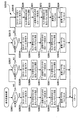
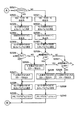
次に、図15に基づいて、本形態(第1形態)の駆動回路200の電気的な接続状態について説明する。図15に示すように、駆動回路200は、遊技表示器40に遊技情報を表示させるために、発光選択回路部210と発光駆動回路部220とを備えている。そして本形態の駆動回路200は、出率表示器300に出率を表示させるために、点灯選択回路部230を備えている点に特徴がある。   Next, based on FIG. 15, an electrical connection state of the drive circuit 200 of the present embodiment (first embodiment) will be described. As shown in FIG. 15, the drive circuit 200 includes a light emission selection circuit unit 210 and a light emission drive circuit unit 220 in order to display game information on the game display 40. The drive circuit 200 of the present embodiment is characterized in that it has a lighting selection circuit section 230 for displaying the output ratio on the output display 300.

発光選択回路部210は、データ情報D[0…3]に基づいて、遊技表示器40が有する4つの発光領域410〜440のうち発光させ得る発光領域を選択するための回路である。この発光選択回路部210は、フリップフロップ(IC1)と、トランジスタアレイ(IC2)とを備えて構成されている。   The light emission selection circuit unit 210 is a circuit for selecting a light emission region that can emit light from the four light emission regions 410 to 440 included in the game display 40, based on the data information D[0... 3]. The light emission selection circuit section 210 includes a flip-flop (IC1) and a transistor array (IC2).

IC1は、8ビット分の入力端子1D〜8Dと、8ビット分の出力端子1Q〜8Qと、クロック入力端子CLKと、クリア入力端子CLRと、その他の端子(VCC端子、GND端子)とを備えている。IC1の入力端子1D〜4Dには、バスラインBLが接続されていて、データ情報D0,D1,D2,D3がそれぞれ入力されるようになっている。またIC1の入力端子5D〜8Dは、グランドに接続されている。これに対して、IC1の出力端子1Q〜4Qには、それぞれ4つの信号伝送ラインS1が接続されている。またIC1の出力端子5Q〜8Qは、未接続になっている。IC1のクリア入力端子CLRには、リセット信号RSTが入力され得る。そしてIC1のクロック入力端子CLKには、遊技制御用マイコン81からのセレクト信号XCSE0(図14参照)が入力されるようになっている。   The IC 1 includes 8-bit input terminals 1D to 8D, 8-bit output terminals 1Q to 8Q, a clock input terminal CLK, a clear input terminal CLR, and other terminals (VCC terminal, GND terminal). ing. The bus line BL is connected to the input terminals 1D to 4D of the IC1 so that the data information D0, D1, D2 and D3 are input respectively. Moreover, the input terminals 5D to 8D of the IC1 are connected to the ground. On the other hand, four signal transmission lines S1 are connected to the output terminals 1Q to 4Q of the IC1, respectively. The output terminals 5Q to 8Q of the IC1 are not connected. The reset signal RST can be input to the clear input terminal CLR of the IC1. The select signal XCSE0 (see FIG. 14) from the game control microcomputer 81 is input to the clock input terminal CLK of IC1.

このIC1は、D型フリップフロップであり、セレクト信号XCSE0の立ち上がりエッジのときに、入力端子1D〜4Dから入力するデータ情報D[0…3]を保持(ラッチ)して、保持した状態のデータ情報D[0…3]を出力端子1Q〜4Qから出力するものである。なおIC1には、例えばテキサスインスツルメント製「SN74HC273N」などの汎用ICを好適に使用できる。   This IC1 is a D-type flip-flop, which holds (latches) the data information D[0...3] input from the input terminals 1D to 4D at the rising edge of the select signal XCSE0, and holds the data. The information D[0...3] is output from the output terminals 1Q to 4Q. A general-purpose IC such as "SN74HC273N" manufactured by Texas Instruments can be preferably used as the IC1.

IC2は、微小入力電流で大電流駆動ができるドライバであり、8ビット分の入力端子IN1〜IN8と、8ビット分の出力端子O1〜O8と、その他の端子(Vs端子、GND端子)とを備えている。IC2の入力端子IN1〜IN4には、4つの信号伝送ラインS1が接続されている。またIC2の入力端子IN5〜IN8は、グランドに接続されている。これに対して、IC2の出力端子O1〜O4には、第1コモン信号ライン(第1発光コモン線)A1と第2コモン信号ライン(第2発光コモン線)A2と第3コモン信号ラインA3と第4コモン信号ラインA4が接続されている。これらコモン信号ラインA1〜A4は、コネクタCN2の1番ピンから4番ピンにつながっていて、上述した遊技表示器40のコモン信号ラインA1〜A4(図12参照)と同じ伝送路になる。またIC2の出力端子O5〜O8は、未接続になっている。なおIC2には、例えばテキサスインスツルメント製「M54562WP」などの汎用ICを好適に使用できる。   The IC2 is a driver that can drive a large current with a minute input current, and has 8-bit input terminals IN1 to IN8, 8-bit output terminals O1 to O8, and other terminals (Vs terminal, GND terminal). I have it. Four signal transmission lines S1 are connected to the input terminals IN1 to IN4 of the IC2. Further, the input terminals IN5 to IN8 of the IC2 are connected to the ground. On the other hand, the output terminals O1 to O4 of the IC2 have a first common signal line (first light emitting common line) A1, a second common signal line (second light emitting common line) A2, and a third common signal line A3. The fourth common signal line A4 is connected. These common signal lines A1 to A4 are connected from the first pin to the fourth pin of the connector CN2 and serve as the same transmission path as the common signal lines A1 to A4 (see FIG. 12) of the game display 40 described above. The output terminals O5 to O8 of the IC2 are unconnected. For the IC2, a general-purpose IC such as "M54562WP" manufactured by Texas Instruments can be preferably used.

発光駆動回路部220は、データ情報D[0…7]に基づいて、4つの発光領域410〜440のうち発光選択回路部210により選択された発光領域にて、8つの遊技用発光部を発光可能にするための回路である。この発光駆動回路部220は、フリップフロップ(IC3)と、トランジスタアレイ(IC4)とを備えて構成されている。   The light emission drive circuit unit 220 emits eight gaming light emission units in the light emission region selected by the light emission selection circuit unit 210 among the four light emission regions 410 to 440 based on the data information D[0... 7]. It is a circuit to enable. The light emission drive circuit unit 220 includes a flip-flop (IC3) and a transistor array (IC4).

IC3は、8ビット分の入力端子1D〜8Dと、8ビット分の出力端子1Q〜8Qと、クロック入力端子CLKと、クリア入力端子CLRと、その他の端子(VCC端子、GND端子)とを備えている。IC3の入力端子1D〜8Dには、バスラインBLが接続されていて、データ情報D0,D1,D2,D3,D4,D5,D6,D7がそれぞれ入力されるようになっている。これに対して、IC3の出力端子1Q〜8Qには、それぞれ8つの信号伝送ラインS2が接続されている。IC3のクリア入力端子CLRには、リセット信号RSTが入力され得る。そしてIC3のクロック入力端子CLKには、遊技制御用マイコン81からのセレクト信号XCSE1(図14参照)が入力されるようになっている。   The IC 3 includes 8-bit input terminals 1D to 8D, 8-bit output terminals 1Q to 8Q, a clock input terminal CLK, a clear input terminal CLR, and other terminals (VCC terminal, GND terminal). ing. The bus line BL is connected to the input terminals 1D to 8D of the IC3, and the data information D0, D1, D2, D3, D4, D5, D6, D7 is input respectively. On the other hand, eight signal transmission lines S2 are connected to the output terminals 1Q to 8Q of the IC3, respectively. The reset signal RST can be input to the clear input terminal CLR of the IC3. The select signal XCSE1 (see FIG. 14) from the game control microcomputer 81 is input to the clock input terminal CLK of the IC3.

このIC3は、D型フリップフロップであり、セレクト信号XCSE1の立ち上がりエッジのときに、入力端子1D〜8Dから入力するデータ情報D[0…7]を保持(ラッチ)して、保持した状態のデータ情報D[0…7]を出力端子1Q〜8Qから出力するものである。なおIC3には、例えばテキサスインスツルメント製「SN74HC273N」などの汎用ICを好適に使用できる。   This IC3 is a D-type flip-flop, which holds (latches) the data information D[0...7] input from the input terminals 1D to 8D at the rising edge of the select signal XCSE1 and holds the data. Information D[0...7] is output from the output terminals 1Q to 8Q. A general-purpose IC such as "SN74HC273N" manufactured by Texas Instruments can be preferably used as the IC3.

IC4は、微小入力電流で大電流駆動ができるドライバであり、8ビット分の入力端子IN1〜IN8と、8ビット分の出力端子O1〜O8と、その他の端子(COM端子、GND端子)とを備えている。IC4の入力端子IN1〜IN8には、8つの信号伝送ラインS2が接続されている。これに対して、IC4の出力端子O1〜O8には、第1データ信号ラインAaから第8データ信号ラインAhまでの各データ信号ラインAa〜Ahが接続されている。これらデータ信号ラインAa〜Ahは、電流制限抵抗RRを介してコネクタCN2の5番ピンから12番ピンにつながっていて、上述した遊技表示器40のデータ信号ラインAa〜Ah(図12参照)と同じ伝送路になる。なおIC4には、例えばテキサスインスツルメント製「M54585WP」などの汎用ICを好適に使用できる。   The IC4 is a driver capable of driving a large current with a minute input current, and has 8-bit input terminals IN1 to IN8, 8-bit output terminals O1 to O8, and other terminals (COM terminal, GND terminal). I have it. Eight signal transmission lines S2 are connected to the input terminals IN1 to IN8 of the IC4. On the other hand, the respective data signal lines Aa to Ah from the first data signal line Aa to the eighth data signal line Ah are connected to the output terminals O1 to O8 of the IC4. These data signal lines Aa to Ah are connected to the 5th to 12th pins of the connector CN2 via the current limiting resistor RR, and are connected to the above-mentioned data signal lines Aa to Ah (see FIG. 12) of the game display 40. It becomes the same transmission line. A general-purpose IC such as "M54585WP" manufactured by Texas Instruments can be preferably used as the IC4.

点灯選択回路部230は、データ情報D[0…3]に基づいて、出率表示器300が有する4つの点灯領域310〜340のうち点灯させ得る点灯領域を選択するための回路である。この点灯選択回路部230は、フリップフロップ(IC5)と、トランジスタアレイ(IC6)とを備えて構成されている。   The lighting selection circuit unit 230 is a circuit for selecting a lighting area that can be turned on among the four lighting areas 310 to 340 included in the output ratio indicator 300, based on the data information D[0... 3]. The lighting selection circuit unit 230 includes a flip-flop (IC5) and a transistor array (IC6).

IC5は、8ビット分の入力端子1D〜8Dと、8ビット分の出力端子1Q〜8Qと、クロック入力端子CLKと、クリア入力端子CLRと、その他の端子(VCC端子、GND端子)とを備えている。IC5の入力端子1D〜4Dには、バスラインBLが接続されていて、データ情報D0,D1,D2,D3がそれぞれ入力されるようになっている。またIC5の入力端子5D〜8Dは、グランドに接続されている。これに対して、IC5の出力端子1Q〜4Qには、それぞれ4つの信号伝送ラインS3が接続されている。またIC5の出力端子5Q〜8Qは、未接続になっている。IC5のクリア入力端子CLRには、リセット信号RSTが入力され得る。そしてIC5のクロック入力端子CLKには、遊技制御用マイコン81からのセレクト信号XCSE10(図14参照)が入力されるようになっている。   The IC 5 includes 8-bit input terminals 1D to 8D, 8-bit output terminals 1Q to 8Q, a clock input terminal CLK, a clear input terminal CLR, and other terminals (VCC terminal, GND terminal). ing. The bus line BL is connected to the input terminals 1D to 4D of the IC 5 so that the data information D0, D1, D2 and D3 are input respectively. Moreover, the input terminals 5D to 8D of the IC 5 are connected to the ground. On the other hand, four signal transmission lines S3 are connected to the output terminals 1Q to 4Q of the IC 5, respectively. Moreover, the output terminals 5Q to 8Q of the IC 5 are not connected. The reset signal RST can be input to the clear input terminal CLR of the IC5. The select signal XCSE10 (see FIG. 14) from the game control microcomputer 81 is input to the clock input terminal CLK of the IC5.

このIC5は、D型フリップフロップであり、セレクト信号XCSE10の立ち上がりエッジのときに、入力端子1D〜4Dから入力するデータ情報D[0…3]を保持(ラッチ)して、保持した状態のデータ情報D[0…3]を出力端子1Q〜4Qから出力するものである。なおIC5には、例えばテキサスインスツルメント製「SN74HC273N」などの汎用ICを好適に使用できる。   The IC 5 is a D-type flip-flop, which holds (latches) the data information D[0...3] input from the input terminals 1D to 4D at the rising edge of the select signal XCSE10 and holds the data. The information D[0...3] is output from the output terminals 1Q to 4Q. A general-purpose IC such as "SN74HC273N" manufactured by Texas Instruments can be preferably used as the IC5.

IC6は、微小入力電流で大電流駆動ができるドライバであり、8ビット分の入力端子IN1〜IN8と、8ビット分の出力端子O1〜O8と、その他の端子(Vs端子、GND端子)とを備えている。IC6の入力端子IN1〜IN4には、4つの信号伝送ラインS3が接続されている。またIC6の入力端子IN5〜IN8は、グランドに接続されている。これに対して、IC6の出力端子O1〜O4には、第1コモン信号ライン(第1点灯コモン線)B1と第2コモン信号ライン(第2点灯コモン線)B2と第3コモン信号ラインB3と第4コモン信号ラインB4が接続されている。これらコモン信号ラインB1〜B4は、上述した出率表示器300のコモン信号ラインB1〜B4(図13参照)と同じ伝送路になる。またIC6の出力端子O5〜O8は、未接続になっている。なおIC6には、例えばテキサスインスツルメント製「M54562WP」などの汎用ICを好適に使用できる。   The IC 6 is a driver that can drive a large current with a minute input current, and has input terminals IN1 to IN8 for 8 bits, output terminals O1 to O8 for 8 bits, and other terminals (Vs terminal, GND terminal). I have it. Four signal transmission lines S3 are connected to the input terminals IN1 to IN4 of the IC6. Further, the input terminals IN5 to IN8 of the IC6 are connected to the ground. On the other hand, the output terminals O1 to O4 of the IC 6 have a first common signal line (first lighting common line) B1, a second common signal line (second lighting common line) B2, and a third common signal line B3. The fourth common signal line B4 is connected. These common signal lines B1 to B4 are the same transmission lines as the common signal lines B1 to B4 (see FIG. 13) of the output ratio indicator 300 described above. The output terminals O5 to O8 of the IC6 are not connected. For the IC 6, a general-purpose IC such as "M54562WP" manufactured by Texas Instruments can be preferably used.

そして本形態では、IC4とコネクタCN2との間に配されている8つのデータ信号ライン(データ線)Aa〜Ahからそれぞれ分岐するように、データ信号ライン(分岐データ線)Ba〜Bhが設けられている。これらデータ信号ラインBa〜Bhは、上述した出率表示器300のデータ信号ラインBa〜Bh(図13参照)と同じ伝送路になる。こうして、IC4の出力端子O1〜O8から出力される信号を、データ信号ラインAa〜Ahによって遊技表示器40に送信できると共に、データ信号ラインBa〜Bhによって出率表示器300にも送信できるようになっている。   In this embodiment, the data signal lines (branch data lines) Ba to Bh are provided so as to branch from the eight data signal lines (data lines) Aa to Ah arranged between the IC 4 and the connector CN2. ing. These data signal lines Ba to Bh serve as the same transmission paths as the data signal lines Ba to Bh (see FIG. 13) of the output ratio indicator 300 described above. In this way, the signals output from the output terminals O1 to O8 of the IC4 can be transmitted to the game display 40 via the data signal lines Aa to Ah, and can also be transmitted to the proportion display device 300 via the data signal lines Ba to Bh. Is becoming

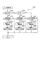
4.遊技制御用マイコン81によるダイナミック点灯制御
次に、遊技制御用マイコン81によるダイナミック点灯制御について、図16〜図34に基づいて説明する。そこで先ず、図16〜図25に基づいて、遊技表示器40に対してダイナミック点灯制御を行う場合について説明する。ここでは一例として、図16(A)に示すように、第1発光領域410にて遊技用発光部LA1,LA2,LA5,LA6を発光させる。即ち、第1特別図柄表示器41aにて大当たり図柄を表示する。次に、図16(B)に示すように、第2発光領域420にて遊技用発光部LA15を発光させる。即ち、第2特別図柄表示器41bにてハズレ図柄を表示する。次に、図16(C)に示すように、第3発光領域430にて遊技用発光部LA17,LA20を発光させる。即ち、普通図柄表示器42に普通ハズレ図柄を表示すると共に、第1特図保留表示器43aにて第1特図保留が1個であることを表示する。次に、図16(D)に示すように、第4発光領域440にて遊技用発光部LA25,LA26,LA30,LA31,LA32を発光させる。即ち、右打ち表示器45にて右打ちすべき状態であることを表示すると共に、ラウンド表示器47にてラウンド数が16Rであることを表示する。
4. Dynamic Lighting Control by Game Control Microcomputer 81 Next, dynamic lighting control by the game control microcomputer 81 will be described with reference to FIGS. 16 to 34. Therefore, first, based on FIGS. 16 to 25, a case where dynamic lighting control is performed on the game display 40 will be described. Here, as an example, as shown in FIG. 16A, the game light emitting portions LA1, LA2, LA5, LA6 are caused to emit light in the first light emitting region 410. That is, the jackpot symbol is displayed on the first special symbol indicator 41a. Next, as shown in FIG. 16B, the gaming light emitting portion LA15 is caused to emit light in the second light emitting region 420. That is, the lost symbol is displayed on the second special symbol display device 41b. Next, as shown in FIG. 16C, the game light emitting portions LA17, LA20 are caused to emit light in the third light emitting region 430. That is, the normal symbol display is displayed on the normal symbol display unit 42, and the first special symbol reservation display unit 43a displays that the first special symbol reservation is one. Next, as shown in FIG. 16D, the game light emitting portions LA25, LA26, LA30, LA31, LA32 are caused to emit light in the fourth light emitting region 440. That is, the right-handed indicator 45 indicates that the state should be right-handed, and the round indicator 47 indicates that the number of rounds is 16R.

なお図17では、各遊技用発光部の発光状態を一旦クリアする場合を示している。これは、遊技表示器40のうち或る発光領域の各遊技用発光部を発光させる場合に、前回(4ms前)の発光領域で発光させた各遊技用発光部の発光状態を反映しないようにするためである。この場合、遊技制御用マイコン81は、図17に示すように、データ情報D[0…7]=D[00000000]を出力する。そして、セレクト信号XCSE1のレベルを「H」レベルに切替える。これにより、IC3によって、データ情報D[00000000]が保持され、8つ全ての信号伝送ラインS2の電圧が「L」レベルになる。その結果、IC4は、8つ全てのデータ信号ラインAa〜Ahの電圧を「L」レベルに切替えて、8個の遊技用発光部に駆動電流を流さない。こうして、各遊技用発光部の発光状態がクリアされる。なお、各出率用点灯部の点灯状態を一旦クリアする場合において、遊技制御用マイコン81の動作も同様であるため、説明を省略する。   Note that FIG. 17 shows a case where the light emitting state of each game light emitting unit is once cleared. This does not reflect the light emitting state of each gaming light emitting unit that was illuminated in the previous (4 ms before) light emitting region when each gaming light emitting unit of the game display 40 emits light. This is because In this case, the game control microcomputer 81 outputs data information D[0...7]=D[00000000], as shown in FIG. Then, the level of the select signal XCSE1 is switched to the "H" level. As a result, the IC 3 holds the data information D[00000000], and the voltage of all eight signal transmission lines S2 becomes “L” level. As a result, the IC 4 switches the voltages of all the eight data signal lines Aa to Ah to the “L” level and does not pass the drive current to the eight game light emitting units. In this way, the light emitting state of each gaming light emitting section is cleared. In the case of once clearing the lighting state of each of the proportion lighting units, the operation of the game control microcomputer 81 is also the same, so description thereof will be omitted.

上述した一例において、遊技制御用マイコン81は、4つの発光領域410〜440のうち発光させ得る発光領域を第1発光領域410にする場合、前回(4ms前)の第4発光領域440での発光状態を反映しないように、先ず図17に示すように発光状態をクリアしておく。次に図18に示すように、データ情報D[0…3]=D[1000]を出力する。そして、セレクト信号XCSE0のレベルを「H」レベルに切替える。これにより、IC1によって、データ情報D[1000]が保持され、4つの信号伝送ラインS1の電圧が上から順番に[HLLL]になる。その結果、IC2は、4つのコモン信号ラインA1〜A4の電圧を[HLLL]に切替える。こうして、第1発光領域410が選択される。   In the above-described example, when the game control microcomputer 81 sets the first light emitting region 410 as the light emitting region that can emit light among the four light emitting regions 410 to 440, it emits light in the fourth light emitting region 440 of the previous time (4 ms ago). First, the light emitting state is cleared as shown in FIG. 17 so as not to reflect the state. Next, as shown in FIG. 18, data information D[0...3]=D[1000] is output. Then, the level of the select signal XCSE0 is switched to the "H" level. As a result, the IC1 holds the data information D[1000], and the voltages of the four signal transmission lines S1 become [HLLL] in order from the top. As a result, the IC2 switches the voltages of the four common signal lines A1 to A4 to [HLLL]. In this way, the first light emitting region 410 is selected.

続いて図19に示すように、遊技制御用マイコン81は、データ情報D[0〜7]=D[11001100]を出力する。そして、セレクト信号XCSE1のレベルを「H」レベルに切替える。これにより、IC3によって、データ情報D[11001100]が保持され、8つの信号伝送ラインS2の電圧が上から順番に[HHLLHHLL]になる。その結果、IC4は、8つのデータ信号ラインAa〜Ahの電圧を[HHLLHHLL]に切替えて、駆動電流を流す。こうして第1発光領域410にて、遊技用発光部LA1,LA2,LA5,LA6が発光する(図16(A)参照)。   Subsequently, as shown in FIG. 19, the game control microcomputer 81 outputs data information D[0-7]=D[11001100]. Then, the level of the select signal XCSE1 is switched to the "H" level. As a result, the IC 3 holds the data information D[11001100], and the voltages of the eight signal transmission lines S2 become [HHLLHHLL] in order from the top. As a result, the IC 4 switches the voltage of the eight data signal lines Aa to Ah to [HHLLHHLL] and passes the drive current. In this way, the game light emitting portions LA1, LA2, LA5, LA6 emit light in the first light emitting region 410 (see FIG. 16A).

その後(4ms後)、遊技制御用マイコン81は、4つの発光領域410〜440のうち発光させ得る発光領域を第2発光領域420にする。この場合、前回(4ms前)の第1発光領域410での発光状態を反映しないように、先ず図17に示すように発光状態をクリアしておく。次に図20に示すように、データ情報D[0…3]=D[0100]を出力する。そして、セレクト信号XCSE0のレベルを「H」レベルに切替える。これにより、IC1によって、データ情報D[0100]が保持され、4つの信号伝送ラインS1の電圧が上から順番に[LHLL]になる。その結果、IC2は、4つのコモン信号ラインA1〜A4の電圧を[LHLL]に切替える。こうして、第2発光領域420が選択される。   After that (after 4 ms), the game control microcomputer 81 sets the second light emitting region 420 as a light emitting region that can emit light among the four light emitting regions 410 to 440. In this case, first, the light emitting state is cleared as shown in FIG. 17 so as not to reflect the light emitting state in the first light emitting region 410 of the previous time (4 ms before). Next, as shown in FIG. 20, data information D[0...3]=D[0100] is output. Then, the level of the select signal XCSE0 is switched to the "H" level. Thereby, the IC1 holds the data information D[0100], and the voltages of the four signal transmission lines S1 become [LHLL] in order from the top. As a result, the IC2 switches the voltages of the four common signal lines A1 to A4 to [LHLL]. In this way, the second light emitting region 420 is selected.

続いて図21に示すように、遊技制御用マイコン81は、データ情報D[0〜7]=D[00001000]を出力する。そして、セレクト信号XCSE1のレベルを「H」レベルに切替える。これにより、IC3によって、データ情報D[00001000]が保持され、8つの信号伝送ラインS2の電圧が上から順番に[LLLLHLLL]になる。その結果、IC4は、8つのデータ信号ラインAa〜Ahの電圧を[LLLLHLLL]に切替えて、駆動電流を流す。こうして第2発光領域420にて、遊技用発光部LA15が発光する(図16(B)参照)。   Then, as shown in FIG. 21, the game control microcomputer 81 outputs data information D[0-7]=D[00001000]. Then, the level of the select signal XCSE1 is switched to the "H" level. As a result, the IC 3 holds the data information D [00001000], and the voltages of the eight signal transmission lines S2 become [LLLLHLLL] in order from the top. As a result, the IC 4 switches the voltage of the eight data signal lines Aa to Ah to [LLLLHLLLL] and supplies a drive current. In this way, the game light emitting section LA15 emits light in the second light emitting area 420 (see FIG. 16B).

その後(4ms後)、遊技制御用マイコン81は、4つの発光領域410〜440のうち発光させ得る発光領域を第3発光領域430にする。この場合、前回(4ms前)の第2発光領域420での発光状態を反映しないように、先ず図17に示すように発光状態をクリアしておく。次に図22に示すように、データ情報D[0…3]=D[0010]を出力する。そして、セレクト信号XCSE0のレベルを「H」レベルに切替える。これにより、IC1によって、データ情報D[0010]が保持され、4つの信号伝送ラインS1の電圧が上から順番に[LLHL]になる。その結果、IC2は、4つのコモン信号ラインA1〜A4の電圧を[LLHL]に切替える。こうして、第3発光領域430が選択される。   After that (after 4 ms), the game control microcomputer 81 sets the third light emitting region 430 as a light emitting region that can emit light among the four light emitting regions 410 to 440. In this case, the light emitting state is first cleared as shown in FIG. 17 so as not to reflect the light emitting state in the second light emitting region 420 of the previous time (4 ms before). Next, as shown in FIG. 22, data information D[0...3]=D[0010] is output. Then, the level of the select signal XCSE0 is switched to the "H" level. As a result, the IC1 holds the data information D[0010], and the voltages of the four signal transmission lines S1 become [LLHL] in order from the top. As a result, the IC2 switches the voltages of the four common signal lines A1 to A4 to [LLHL]. In this way, the third light emitting region 430 is selected.

続いて図23に示すように、遊技制御用マイコン81は、データ情報D[0〜7]=D[10010000]を出力する。そして、セレクト信号XCSE1のレベルを「H」レベルに切替える。これにより、IC3によって、データ情報D[10010000]が保持され、8つの信号伝送ラインS2の電圧が上から順番に[HLLHLLLL]になる。その結果、IC4は、8つのデータ信号ラインAa〜Ahの電圧を[HLLHLLLL]に切替えて、駆動電流を流す。こうして第3発光領域430にて、遊技用発光部LA17,LA20が発光する(図16(C)参照)。   Subsequently, as shown in FIG. 23, the game control microcomputer 81 outputs data information D[0-7]=D[10010000]. Then, the level of the select signal XCSE1 is switched to the "H" level. As a result, the IC 3 holds the data information D [10010000], and the voltages of the eight signal transmission lines S2 become [HLLHLLLL] in order from the top. As a result, the IC 4 switches the voltage of the eight data signal lines Aa to Ah to [HLLHLLLL] and passes the drive current. In this way, the game light emitting units LA17 and LA20 emit light in the third light emitting region 430 (see FIG. 16C).

その後(4ms後)、遊技制御用マイコン81は、4つの発光領域410〜440のうち発光させ得る発光領域を第4発光領域440にする。この場合、前回(4ms前)の第3発光領域430での発光状態を反映しないように、先ず図17に示すように発光状態をクリアしておく。次に図24に示すように、データ情報D[0…3]=D[0001]を出力する。そして、セレクト信号XCSE0のレベルを「H」レベルに切替える。これにより、IC1によって、データ情報D[0001]が保持され、4つの信号伝送ラインS1の電圧が上から順番に[LLLH]になる。その結果、IC2は、4つのコモン信号ラインA1〜A4の電圧を[LLLH]に切替える。こうして、第4発光領域440が選択される。   After that (4 ms later), the game control microcomputer 81 sets the light emitting area that can emit light among the four light emitting areas 410 to 440 to the fourth light emitting area 440. In this case, the light emitting state is first cleared as shown in FIG. 17 so as not to reflect the light emitting state in the third light emitting region 430 of the previous time (4 ms before). Next, as shown in FIG. 24, the data information D[0...3]=D[0001] is output. Then, the level of the select signal XCSE0 is switched to the "H" level. As a result, the IC1 holds the data information D[0001], and the voltages of the four signal transmission lines S1 sequentially become [LLLH] from the top. As a result, the IC2 switches the voltages of the four common signal lines A1 to A4 to [LLLH]. Thus, the fourth light emitting area 440 is selected.

続いて図25に示すように、遊技制御用マイコン81は、データ情報D[0〜7]=D[11000111]を出力する。そして、セレクト信号XCSE1のレベルを「H」レベルに切替える。これにより、IC3によって、データ情報D[11000111]が保持され、8つの信号伝送ラインS2の電圧が上から順番に[HHLLLHHH]になる。その結果、IC4は、8つのデータ信号ラインAa〜Ahの電圧を[HHLLLHHH]に切替えて、駆動電流を流す。こうして第4発光領域440にて、遊技用発光部LA25,LA26,LA30,LA31,LA32が発光する(図16(D)参照)。以後、遊技制御用マイコン81は、4ms毎に上述したように、第1発光領域410での発光制御、第2発光領域420での発光制御、第3発光領域430での発光制御、第4発光領域440での発光制御を繰り返すことになる。   Subsequently, as shown in FIG. 25, the game control microcomputer 81 outputs data information D[0-7]=D[110011111]. Then, the level of the select signal XCSE1 is switched to the "H" level. As a result, the IC 3 holds the data information D[11000111], and the voltages of the eight signal transmission lines S2 become [HHLLLLHHH] in order from the top. As a result, the IC 4 switches the voltage of the eight data signal lines Aa to Ah to [HHLLLLHHH] and supplies a drive current. In this way, the game light emitting portions LA25, LA26, LA30, LA31, LA32 emit light in the fourth light emitting region 440 (see FIG. 16D). Thereafter, the game control microcomputer 81, every 4 ms, as described above, the emission control in the first emission region 410, the emission control in the second emission region 420, the emission control in the third emission region 430, the fourth emission. The light emission control in the area 440 is repeated.

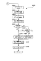
次に、図26〜図34に基づいて、出率表示器300に対してダイナミック点灯制御を行う場合について説明する。ここでは一例として、図26(A)に示すように、第1点灯領域310にて出率用点灯部LB1,LB3,LB4,LB5,LB6,LB7を点灯させる。即ち、第1点灯領域310にて「6」を表示する。次に、図26(B)に示すように、第2点灯領域320にて出率用点灯部LB9,LB10,LB11,LB12,LB13,LB14を点灯させる。即ち、第2点灯領域320にて「0」を表示する。次に、図26(C)に示すように、第3点灯領域330にて出率用点灯部LB17,LB18,LB20,LB21,LB23を点灯させる。即ち、第3点灯領域330にて「2」を表示する。次に、図26(D)に示すように、第4点灯領域340にて出率用点灯部LB26,LB27を点灯させる。即ち、第4点灯領域340にて「1」を表示する。   Next, a case where the dynamic lighting control is performed on the output ratio indicator 300 will be described with reference to FIGS. 26 to 34. Here, as an example, as shown in FIG. 26A, in the first lighting region 310, the output lighting units LB1, LB3, LB4, LB5, LB6, LB7 are lit. That is, “6” is displayed in the first lighting area 310. Next, as shown in FIG. 26B, the output lighting units LB9, LB10, LB11, LB12, LB13, LB14 are lit in the second lighting region 320. That is, “0” is displayed in the second lighting area 320. Next, as shown in FIG. 26(C), the output lighting units LB17, LB18, LB20, LB21, LB23 are lit in the third lighting region 330. That is, “2” is displayed in the third lighting area 330. Next, as shown in FIG. 26(D), the proportion lighting units LB26 and LB27 are lit in the fourth lighting region 340. That is, “1” is displayed in the fourth lighting area 340.

上述した一例において、遊技制御用マイコン81は、4つの点灯領域310〜340のうち点灯させ得る点灯領域を第1点灯領域310にする場合、前回(4ms前)の第4点灯領域340での点灯状態を反映しないように、先ず図17に示すように点灯状態をクリアしておく。次に図27に示すように、データ情報D[0…3]=D[1000]を出力する。そして、セレクト信号XCSE10のレベルを「H」レベルに切替える。これにより、IC5によって、データ情報D[1000]が保持され、4つの信号伝送ラインS3の電圧が上から順番に[HLLL]になる。その結果、IC6は、4つのコモン信号ラインB1〜B4の電圧を[HLLL]に切替える。こうして、第1点灯領域310が選択される。   In the above-described example, when the gaming control microcomputer 81 sets the lighting region that can be lighted among the four lighting regions 310 to 340 as the first lighting region 310, the previous lighting (4 ms before) in the fourth lighting region 340. First, the lighting state is cleared as shown in FIG. 17 so that the state is not reflected. Next, as shown in FIG. 27, data information D[0...3]=D[1000] is output. Then, the level of the select signal XCSE10 is switched to the "H" level. As a result, the IC 5 holds the data information D[1000] and the voltages of the four signal transmission lines S3 become [HLLL] in order from the top. As a result, the IC 6 switches the voltages of the four common signal lines B1 to B4 to [HLLL]. In this way, the first lighting region 310 is selected.

続いて図28に示すように、遊技制御用マイコン81は、データ情報D[0〜7]=D[10111110]を出力する。そして、セレクト信号XCSE1のレベルを「H」レベルに切替える。これにより、IC3によって、データ情報D[10111110]が保持され、8つの信号伝送ラインS2の電圧が上から順番に[HLHHHHHL]になる。その結果、IC4は、8つのデータ信号ラインBa〜Bhの電圧を[HLHHHHHL]に切替えて、駆動電流を流す。こうして第1点灯領域310にて、出率用点灯部LB1,LB3,LB4,LB5,LB6,LB7が点灯する(図26(A)参照)。   Subsequently, as shown in FIG. 28, the game control microcomputer 81 outputs data information D[0-7]=D[10111110]. Then, the level of the select signal XCSE1 is switched to the "H" level. As a result, the IC 3 holds the data information D[10111110], and the voltages of the eight signal transmission lines S2 become [HLHHHHHL] in order from the top. As a result, the IC 4 switches the voltages of the eight data signal lines Ba to Bh to [HLHHHHHL] and supplies a drive current. In this way, in the 1st lighting area|region 310, the lighting part LB1, LB3, LB4, LB5, LB6, LB7 is lighted (refer FIG. 26(A)).

その後(4ms後)、遊技制御用マイコン81は、4つの点灯領域310〜340のうち点灯させ得る点灯領域を第2点灯領域320にする。この場合、前回(4ms前)の第1点灯領域310での点灯状態を反映しないように、先ず図17に示すように点灯状態をクリアしておく。次に図29に示すように、データ情報D[0…3]=D[0100]を出力する。そして、セレクト信号XCSE10のレベルを「H」レベルに切替える。これにより、IC5によって、データ情報D[0100]が保持され、4つの信号伝送ラインS3の電圧が上から順番に[LHLL]になる。その結果、IC6は、4つのコモン信号ラインB1〜B4の電圧を[LHLL]に切替える。こうして、第2点灯領域320が選択される。   After that (4 ms later), the game control microcomputer 81 sets a lighting region that can be lighted among the four lighting regions 310 to 340 as the second lighting region 320. In this case, the lighting state is first cleared as shown in FIG. 17 so that the lighting state in the first lighting region 310 of the previous time (4 ms before) is not reflected. Next, as shown in FIG. 29, data information D[0...3]=D[0100] is output. Then, the level of the select signal XCSE10 is switched to the "H" level. As a result, the IC 5 holds the data information D[0100], and the voltages of the four signal transmission lines S3 sequentially become [LHLL] from the top. As a result, the IC 6 switches the voltages of the four common signal lines B1 to B4 to [LHLL]. In this way, the second lighting region 320 is selected.

続いて図30に示すように、遊技制御用マイコン81は、データ情報D[0〜7]=D[11111100]を出力する。そして、セレクト信号XCSE1のレベルを「H」レベルに切替える。これにより、IC3によって、データ情報D[11111100]が保持され、8つの信号伝送ラインS2の電圧が上から順番に[HHHHHHLL]になる。その結果、IC4は、8つのデータ信号ラインBa〜Bhの電圧を[HHHHHHLL]に切替えて、駆動電流を流す。こうして第2点灯領域320にて、出率用点灯部LB9,LB10,LB11,LB12,LB13,LB14が点灯する(図26(B)参照)。   Subsequently, as shown in FIG. 30, the game control microcomputer 81 outputs data information D[0-7]=D[11111100]. Then, the level of the select signal XCSE1 is switched to the "H" level. As a result, the IC 3 holds the data information D[11111100], and the voltages of the eight signal transmission lines S2 become [HHHHHHLL] in order from the top. As a result, the IC 4 switches the voltages of the eight data signal lines Ba to Bh to [HHHHHHLL] and supplies a drive current. In this way, in the second lighting region 320, the output lighting units LB9, LB10, LB11, LB12, LB13, LB14 are lit (see FIG. 26B).

その後(4ms後)、遊技制御用マイコン81は、4つの点灯領域310〜340のうち点灯させ得る点灯領域を第3点灯領域330にする。この場合、前回(4ms前)の第2点灯領域320での点灯状態を反映しないように、先ず図17に示すように点灯状態をクリアしておく。次に図31に示すように、データ情報D[0…3]=D[0010]を出力する。そして、セレクト信号XCSE10のレベルを「H」レベルに切替える。これにより、IC5によって、データ情報D[0010]が保持され、4つの信号伝送ラインS3の電圧が上から順番に[LLHL]になる。その結果、IC6は、4つのコモン信号ラインB1〜B4の電圧を[LLHL]に切替える。こうして、第3点灯領域330が選択される。   After that (after 4 ms), the game control microcomputer 81 sets a lighting region that can be lighted among the four lighting regions 310 to 340 as the third lighting region 330. In this case, the lighting state is first cleared as shown in FIG. 17 so as not to reflect the lighting state in the second lighting region 320 of the previous time (4 ms before). Next, as shown in FIG. 31, the data information D[0...3]=D[0010] is output. Then, the level of the select signal XCSE10 is switched to the "H" level. As a result, the IC 5 holds the data information D[0010], and the voltages of the four signal transmission lines S3 become [LLHL] in order from the top. As a result, the IC 6 switches the voltages of the four common signal lines B1 to B4 to [LLHL]. In this way, the third lighting region 330 is selected.

続いて図32に示すように、遊技制御用マイコン81は、データ情報D[0〜7]=D[11011010]を出力する。そして、セレクト信号XCSE1のレベルを「H」レベルに切替える。これにより、IC3によって、データ情報D[11011010]が保持され、8つの信号伝送ラインS2の電圧が上から順番に[HHLHHLHL]になる。その結果、IC4は、8つのデータ信号ラインBa〜Bhの電圧を[HHLHHLHL]に切替えて、駆動電流を流す。こうして第3点灯領域330にて、出率用点灯部LB17,LB18,LB20,LB21,LB23が点灯する(図26(C)参照)。   Subsequently, as shown in FIG. 32, the game control microcomputer 81 outputs data information D[0-7]=D[11011010]. Then, the level of the select signal XCSE1 is switched to the "H" level. As a result, the IC 3 holds the data information D[11011010], and the voltages of the eight signal transmission lines S2 become [HHLHHLHL] in order from the top. As a result, the IC 4 switches the voltages of the eight data signal lines Ba to Bh to [HHLHHLHL] and supplies a drive current. In this way, in the 3rd lighting area 330, the lighting parts LB17, LB18, LB20, LB21, LB23 for ratio lights up (refer FIG.26(C)).

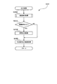
その後(4ms後)、遊技制御用マイコン81は、4つの点灯領域310〜340のうち点灯させ得る点灯領域を第4点灯領域340にする。この場合、前回(4ms前)の第3点灯領域330での点灯状態を反映しないように、先ず図17に示すように点灯状態をクリアしておく。次に図33に示すように、データ情報D[0…3]=D[0001]を出力する。そして、セレクト信号XCSE10のレベルを「H」レベルに切替える。これにより、IC5によって、データ情報D[0001]が保持され、4つの信号伝送ラインS3の電圧が上から順番に[LLLH]になる。その結果、IC6は、4つのコモン信号ラインB1〜B4の電圧を[LLLH]に切替える。こうして、第4点灯領域340が選択される。   After that (4 ms later), the game control microcomputer 81 sets a lighting region that can be lighted among the four lighting regions 310 to 340 to the fourth lighting region 340. In this case, the lighting state is first cleared as shown in FIG. 17 so as not to reflect the lighting state in the third lighting region 330 of the previous time (4 ms before). Next, as shown in FIG. 33, the data information D[0...3]=D[0001] is output. Then, the level of the select signal XCSE10 is switched to the "H" level. As a result, the IC 5 holds the data information D[0001], and the voltages of the four signal transmission lines S3 become [LLLH] in order from the top. As a result, the IC 6 switches the voltages of the four common signal lines B1 to B4 to [LLLH]. In this way, the fourth lighting region 340 is selected.

続いて図34に示すように、遊技制御用マイコン81は、データ情報D[0〜7]=D[01100000]を出力する。そして、セレクト信号XCSE1のレベルを「H」レベルに切替える。これにより、IC3によって、データ情報D[01100000]が保持され、8つの信号伝送ラインS2の電圧が上から順番に[LHHLLLLL]になる。その結果、IC4は、8つのデータ信号ラインBa〜Bhの電圧を[LHHLLLLL]に切替えて、駆動電流を流す。こうして第4点灯領域340にて、出率用点灯部LB26,LB27が点灯する(図26(D)参照)。以後、遊技制御用マイコン81は、4ms毎に上述したように、第1点灯領域310での点灯制御、第2点灯領域320での点灯制御、第3点灯領域330での点灯制御、第4点灯領域340での点灯制御を繰り返すことになる。   Subsequently, as shown in FIG. 34, the game control microcomputer 81 outputs data information D[0-7]=D[01100000]. Then, the level of the select signal XCSE1 is switched to the "H" level. As a result, the IC 3 holds the data information D[01100000], and the voltages of the eight signal transmission lines S2 become [LHHLLLLLL] sequentially from the top. As a result, the IC 4 switches the voltage of the eight data signal lines Ba to Bh to [LHHLLLLLL] and passes the drive current. In this way, in the 4th lighting area 340, the lighting parts LB26 and LB27 for output lights (refer FIG.26(D)). Thereafter, the game control microcomputer 81, every 4 ms, as described above, lighting control in the first lighting region 310, lighting control in the second lighting region 320, lighting control in the third lighting region 330, fourth lighting. The lighting control in the area 340 is repeated.

5.駆動回路200の技術的意義
次に、本形態の駆動回路200(図15参照)の技術的意義について説明する。そこで第1比較例及び第2比較例と比較しながら説明する。第1比較例として、図35に示すような駆動回路200Xが考えられる。この駆動回路200Xは、上述した発光選択回路部210と発光駆動回路部220という既存の回路の他、出率表示器300の4つの点灯領域310〜340のうち点灯させ得る点灯領域を選択する点灯選択回路部210Xと、選択された点灯領域にて8つの各出率用点灯部を点灯可能にする点灯駆動回路部220Xとを備えている。
5. Technical Meaning of Drive Circuit 200 Next, the technical meaning of the drive circuit 200 (see FIG. 15) of the present embodiment will be described. Therefore, description will be made while comparing with the first comparative example and the second comparative example. As a first comparative example, a drive circuit 200X as shown in FIG. 35 can be considered. This drive circuit 200X is a lighting circuit that selects a lighting region that can be lighted from among the four lighting regions 310 to 340 of the output indicator 300, in addition to the existing circuits of the light emission selection circuit unit 210 and the light emission driving circuit unit 220 described above. The selection circuit unit 210X and the lighting drive circuit unit 220X that enables lighting of each of the eight emission ratio lighting units in the selected lighting region are provided.

点灯選択回路部210Xは、発光選択回路部210と同じ構成であり、フリップフロップ(IC1X)とトランジスタアレイ(ICX2)とを備えている。また点灯駆動回路部220Xは、発光駆動回路部220と同じ構成であり、フリップフロップ(IC3X)とトランジスタアレイ(IC4X)とを備えている。そして、点灯選択回路部210X及び点灯駆動回路部220Xと出率表示器300との接続は、発光選択回路部210及び発光駆動回路部220と遊技表示器40との接続と全く同じになっている。従って、第1比較例の駆動回路200Xでは、遊技表示器40を発光させるための既存の4個のIC(集積回路)に対して、4個のICを新たに追加していることになる。   The lighting selection circuit unit 210X has the same configuration as the light emission selection circuit unit 210, and includes a flip-flop (IC1X) and a transistor array (ICX2). The lighting drive circuit unit 220X has the same configuration as the light emission drive circuit unit 220, and includes a flip-flop (IC3X) and a transistor array (IC4X). Then, the connection between the lighting selection circuit unit 210X and the lighting drive circuit unit 220X and the output ratio indicator 300 is exactly the same as the connection between the light emission selection circuit unit 210 and the light emission drive circuit unit 220 and the game display 40. . Therefore, in the drive circuit 200X of the first comparative example, four ICs are newly added to the existing four ICs (integrated circuits) for causing the game display 40 to emit light.

ところで主制御基板80は、技術的制約が大きいものであり、各メーカーではその技術的制約の中で最大限の性能を発揮できるように主制御基板80を設計している。そのため主制御基板80には、出率表示器300やその駆動回路を新たに配置するためのスペースの余裕があまり無い。そこで既存の主制御基板80よりも大きな主制御基板を用いることが考えられるが、主制御基板の大きさ等による設計変更は、その他の制御基板の設計にも影響を与えてしまい、莫大な費用がかかってしまう。よって、既存の主制御基板80上の各部品を寄せてスペースを作ることが現実的である。しかしながら、あまりに部品が密集し過ぎると今度はノイズに対して弱くなってしまう。即ち、主制御基板の各部品が密集し過ぎると、グランドが少なくなってしまい、ノイズに弱い設計になってしまう。以上の観点により、主制御基板80に配置する新たな部品はできるだけ少ないことが望ましい。   By the way, the main control board 80 has large technical restrictions, and each manufacturer designs the main control board 80 so as to exhibit the maximum performance within the technical restrictions. Therefore, the main control board 80 does not have enough space for newly disposing the proportion indicator 300 and its drive circuit. Therefore, it is conceivable to use a main control board larger than the existing main control board 80, but a design change due to the size of the main control board or the like also affects the design of other control boards, resulting in enormous cost. It will cost you. Therefore, it is realistic to bring the parts on the existing main control board 80 close together to make a space. However, if the parts are too close together, it becomes vulnerable to noise. That is, if the parts of the main control board are too close together, the ground will be reduced and the design will be weak against noise. From the above viewpoints, it is desirable that the number of new components to be arranged on the main control board 80 be as small as possible.

そこで本形態の駆動回路200によれば、図15に示すように、遊技表示器40を発光させるための既存の4個のIC(集積回路)に対して、2個のIC(点灯選択回路部230)だけを追加している。つまり、データ信号ラインAa〜Ahから分岐するデータ信号ラインBa〜Bhを出率表示器300につなぐことで、第1比較例のような点灯駆動回路部220X(図35参照)を省くことにしている。従って、図35に示す第1比較例の駆動回路200Xよりも、追加するICの数を少なくすることが可能であり、配置スペースの観点において主制御基板80に実装し易くすることが可能である。そして、主制御基板80上の各部品が密集し過ぎるのを回避して、ノイズに弱い設計になるのをできるだけ防ぐことが可能である。   Therefore, according to the drive circuit 200 of the present embodiment, as shown in FIG. 15, two ICs (lighting selection circuit unit) are provided to four existing ICs (integrated circuits) for causing the game display 40 to emit light. 230) is added. That is, by connecting the data signal lines Ba to Bh branched from the data signal lines Aa to Ah to the output ratio indicator 300, the lighting drive circuit unit 220X (see FIG. 35) as in the first comparative example is omitted. There is. Therefore, the number of ICs to be added can be reduced as compared with the drive circuit 200X of the first comparative example shown in FIG. 35, and it is possible to facilitate mounting on the main control board 80 from the viewpoint of arrangement space. . Then, it is possible to prevent the respective components on the main control board 80 from becoming too close to each other and prevent the design from being susceptible to noise as much as possible.

また第2比較例として、図36に示すようなダイナミック点灯制御を行うことが考えられる。即ち、第2比較例では、先ず図36(A)に示すように、遊技表示器40の第1発光領域410での発光制御を行う。続いて4ms後に図36(B)に示すように、第2発光領域420での発光制御を行う。続いて4ms後に図36(C)に示すように、第3発光領域430での発光制御を行う。続いて4ms後に図36(D)に示すように、第4発光領域440での発光制御を行う。続いて4ms後に図36(E)に示すように、出率表示器300の第1点灯領域310での点灯制御を行う。続いて4ms後に図36(F)に示すように、第2点灯領域320での点灯制御を行う。続いて4ms後に図36(G)に示すように、第3点灯領域330での点灯制御を行う。続いて4ms後に図36(H)に示すように、第4点灯領域340での点灯制御を行う。その後同様に、図36(A)〜(H)に示すダイナミック点灯制御を繰り返す。従って、第2比較例では、或る発光領域又は点灯領域に着目すれば、32msの周期で発光制御又は点灯制御がなされていることになる。   As a second comparative example, it is possible to perform dynamic lighting control as shown in FIG. That is, in the second comparative example, first, as shown in FIG. 36(A), light emission control is performed in the first light emitting area 410 of the game display 40. Subsequently, after 4 ms, as shown in FIG. 36B, light emission control in the second light emitting region 420 is performed. Subsequently, after 4 ms, as shown in FIG. 36C, light emission control in the third light emitting region 430 is performed. Subsequently, after 4 ms, as shown in FIG. 36D, light emission control in the fourth light emitting region 440 is performed. Subsequently, after 4 ms, as shown in FIG. 36(E), the lighting control in the first lighting region 310 of the output indicator 300 is performed. Subsequently, 4 ms later, as shown in FIG. 36(F), lighting control in the second lighting region 320 is performed. Subsequently, 4 ms later, as shown in FIG. 36(G), lighting control in the third lighting region 330 is performed. Subsequently, 4 ms later, as shown in FIG. 36(H), lighting control in the fourth lighting region 340 is performed. Thereafter, similarly, the dynamic lighting control shown in FIGS. 36(A) to (H) is repeated. Therefore, in the second comparative example, if attention is paid to a certain light emitting region or a light emitting region, the light emitting control or the light emitting control is performed in a cycle of 32 ms.

しかしながら第2比較例のダイナミック点灯制御では、発光制御(点灯制御)の周期が長くて、遊技表示器40での表示及び出率表示器300での表示が瞬くおそれがあった。つまり、遊技表示器40で発光し続けている状態を見せる状況にも拘わらず、点滅しているように見えたり、出率表示器300で点灯し続けている状態を見せる状況にも拘わらず、点滅しているように見えるおそれがあった。   However, in the dynamic lighting control of the second comparative example, the cycle of the light emission control (lighting control) is long, and the display on the game display 40 and the display on the proportion display 300 may be blinking. That is, in spite of the situation in which the gaming display 40 shows the state of continuing to emit light, in spite of the situation in which it appears to be blinking or the state of the proportion display 300 shows in the state of continuously lighting, There was a risk that it would seem to be blinking.

そこで本形態の駆動回路200によれば、或る発光領域又は点灯領域において、16msの周期で発光制御又は点灯制御がなされるように構成されている。つまり、遊技表示器40の発光領域410〜440での発光制御と、出率表示器300の点灯領域310〜340での点灯制御とを択一的に実行するようにして、従来と同じ周期(16ms)のままダイナミック点灯制御を可能にしている。従って、遊技表示器40での表示及び出率表示器300での表示が瞬くのを防ぐことが可能である。以上要するに、本形態の駆動回路200の技術的意義は、遊技表示器40又は出率表示器300でダイナミック点灯制御の周期を従来よりも長くなるのを回避しつつ、主制御基板80に実装する際の省スペース化を実現できることにある。   Therefore, according to the drive circuit 200 of the present embodiment, the light emission control or the light emission control is performed at a cycle of 16 ms in a certain light emission region or a light emission region. In other words, the light emission control in the light emission regions 410 to 440 of the game display 40 and the light emission control in the light emission regions 310 to 340 of the output ratio display 300 are selectively executed, and the same cycle as the conventional cycle ( 16 ms), the dynamic lighting control is enabled. Therefore, it is possible to prevent the display on the game display 40 and the display on the proportion display 300 from blinking. In short, the technical significance of the drive circuit 200 of the present embodiment is to be mounted on the main control board 80 while avoiding that the cycle of dynamic lighting control in the game display 40 or the proportion display 300 becomes longer than in the past. In that case, it is possible to save space.

6.大当たり等の説明
本形態のパチンコ遊技機1では、大当たり抽選(特別図柄抽選)の結果として、「大当たり」と「はずれ」がある。「大当たり」のときには、特別図柄表示器41に「大当たり図柄」が停止表示される。「はずれ」のときには、特別図柄表示器41に「ハズレ図柄」が停止表示される。大当たりに当選すると、停止表示された特別図柄の種類(大当たりの種類)に応じた開放パターンにて、大入賞口(第1大入賞口30および第2大入賞口35)を開放させる「大当たり遊技」が実行される。大当たり遊技を特別遊技ともいう。
6. Explanation of big hit etc. In the pachinko gaming machine 1 of the present embodiment, there are "big hit" and "off" as a result of the big hit lottery (special symbol lottery). At the time of "big hit", the "big hit symbol" is stopped and displayed on the special symbol display 41. In the case of "disappear", the "missing symbol" is stopped and displayed on the special symbol display 41. If you win the jackpot, you open the special winning opening (first big winning opening 30 and second big winning opening 35) in an opening pattern according to the type of special symbol that is stopped (type of big winning) Is executed. The jackpot game is also called a special game.

大当たり遊技は、本形態では、複数回のラウンド遊技(単位開放遊技)と、初回のラウンド遊技が開始される前のオープニング(OPとも表記する)と、最終回のラウンド遊技が終了した後のエンディング(EDとも表記する)とを含んでいる。各ラウンド遊技は、OPの終了又は前のラウンド遊技の終了によって開始し、次のラウンド遊技の開始又はEDの開始によって終了する。ラウンド遊技間の大入賞口の閉鎖の時間(インターバル時間)は、その閉鎖前の開放のラウンド遊技に含まれる。   In the present embodiment, the jackpot game is a plurality of round games (a unit opening game), an opening (also referred to as OP) before the first round game is started, and an ending after the final round game is finished. (Also referred to as ED). Each round game starts by the end of OP or the end of the previous round game, and ends by the start of the next round game or the start of ED. The closing time (interval time) of the special winning opening between round games is included in the opening round game before the closing.

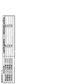
大当たりには複数の種別がある。大当たりの種別は図37に示す通りである。図37に示すように、本形態では大きく分けて2つの種別がある。特定大当たりと通常大当たりである。特定大当たりを「Vロング大当たり」ともいい、通常大当たりを「Vショート大当たり」ともいう。「Vロング大当たり」は、その大当たり遊技中に特定領域39への遊技球の通過が容易に可能な第1開放パターン(Vロング開放パターン)で開閉部材32及び開閉部材37を作動させる大当たりである。「Vショート大当たり」は、その大当たり遊技中に特定領域39への遊技球の通過が不可能又は困難な第2開放パターン(Vショート開放パターン)で開閉部材32及び開閉部材37を作動させる大当たりである。   There are multiple types of jackpots. The types of jackpots are as shown in FIG. As shown in FIG. 37, in this embodiment, there are roughly two types. It is a specific jackpot and a regular jackpot. The specific jackpot is also called “V long jackpot”, and the regular jackpot is also called “V short jackpot”. The “V long jackpot” is a jackpot that operates the opening/closing member 32 and the opening/closing member 37 in a first opening pattern (V long opening pattern) that allows the game ball to easily pass to the specific area 39 during the jackpot game. .. The "V short jackpot" is a jackpot that operates the opening/closing member 32 and the opening/closing member 37 in a second opening pattern (V short opening pattern) in which it is impossible or difficult for the game ball to pass to the specific area 39 during the jackpot game. is there.

より具体的には、特図1の抽選(第1特別図柄の抽選)にて当選可能な「Vロング大当たり」は、1Rから8Rまでは第1大入賞口30を1R当たり最大29.5秒にわたって開放し、9Rから15Rまでは第1大入賞口30を1R当たり最大0.1秒にわたって開放し、16R(最終ラウンド)では第2大入賞口35を1R当たり最大29.5秒にわたって開放する大当たりである。つまり、この大当たりの総ラウンド数は16Rであるものの、実質的なラウンド数は9Rである。実質的なラウンド数とは、1ラウンド当たりの入賞上限個数(本形態では8個)まで遊技球が入賞可能なラウンド数のことである。このVロング大当たりでは9Rから15Rまでは、大入賞口の開放時間が極めて短く、賞球の見込めないラウンドとなっている。なお、16Rでは、第2大入賞口35内の特定領域39への通過が容易に可能である。また、特図1の抽選によって「特定大当たり」に当選した場合には、第1特別図柄表示器41aに「特図1_特定図柄」が停止表示される。   More specifically, the "V long jackpot" that can be won in the lottery of the special map 1 (the lottery of the first special symbol) is a maximum of 29.5 seconds per 1R for the first special winning opening 30 from 1R to 8R. The first big winning opening 30 is opened for a maximum of 0.1 seconds per 1R from 9R to 15R, and the second large winning opening 35 is opened for a maximum of 29.5 seconds per 1R in 16R (final round). It's a big hit. That is, the total number of rounds for this jackpot is 16R, but the actual number of rounds is 9R. The substantial number of rounds is the number of rounds in which game balls can win up to the maximum number of winnings per round (8 in this embodiment). In this V long jackpot, from 9R to 15R, the opening time of the special winning opening is extremely short, and it is a round in which no prize ball can be expected. In 16R, the passage to the specific area 39 in the second special winning opening 35 is easily possible. Further, when the "specific jackpot" is won by the lottery of special figure 1, "special figure 1_specific symbol" is stopped and displayed on the first special symbol display 41a.

また、特図2の抽選(第2特別図柄の抽選)にて当選可能な「Vロング大当たり」は、1Rから15Rまでは第1大入賞口30を1R当たり最大29.5秒にわたって開放し、16R(最終ラウンド)では第2大入賞口35を1R当たり最大29.5秒にわたって開放する大当たりである。つまり、この大当たりは実質的なラウンド数も16Rである。もちろん、16Rでは、第2大入賞口35内の特定領域39への通過が容易に可能である。特図2の抽選によって「特定大当たり」に当選した場合には、第2特別図柄表示器41bに「特図2_特定図柄」が停止表示される。   In addition, the "V long jackpot" that can be won in the lottery of special map 2 (lottery of the second special symbol) is to open the first big winning opening 30 for a maximum of 29.5 seconds per 1R from 1R to 15R, In the 16R (final round), the second special winning opening 35 is a big jackpot that opens for a maximum of 29.5 seconds per 1R. In other words, the actual number of rounds for this jackpot is 16R. Of course, with 16R, it is possible to easily pass to the specific area 39 in the second special winning opening 35. When the "specific jackpot" is won by the lottery of special figure 2, "special figure 2_specific symbol" is stopped and displayed on the second special symbol display 41b.

これに対して、特図1の抽選にて当選可能な「Vショート大当たり」は、1Rから8Rまでは第1大入賞口30を1R当たり最大29.5秒にわたって開放し、9Rから15Rまでは第1大入賞口30を1R当たり最大0.1秒にわたって開放し、16R(最終ラウンド)では第2大入賞口35を1R当たり最大0.1秒にわたって開放する大当たりである。つまり、この大当たりの総ラウンド数は16Rであるものの、実質的なラウンド数は8Rである。   On the other hand, the "V short jackpot" that can be won in the lottery of Special Figure 1 opens the 1st special winning opening 30 for a maximum of 29.5 seconds per 1R from 1R to 8R, and from 9R to 15R It is a jackpot in which the first special winning opening 30 is opened for a maximum of 0.1 seconds per 1R, and the second special winning opening 35 is opened for a maximum of 0.1 seconds per 1R in 16R (final round). That is, the total number of rounds for this jackpot is 16R, but the actual number of rounds is 8R.

このVショート大当たりにおける16Rでは、第2大入賞口35の開放時間が極めて短く、第2大入賞口35内の特定領域39に遊技球が通過することはほぼ不可能となっている。なお、Vショート大当たりにおける16Rでは、第2大入賞口35の開放時間が短いことだけでなく、第2大入賞口35の開放タイミングと振分部材71の作動タイミング(第2の状態(図4(B)参照)から第1の状態(図4(A)参照)に制御されるタイミング)との関係からも、特定領域39に遊技球が通過することはほぼ不可能となっている。特図1の抽選によって「通常大当たり」に当選した場合には、第1特別図柄表示器41aに「特図1_通常図柄」が停止表示される。   At 16R in this V-short jackpot, the opening time of the second special winning opening 35 is extremely short, and it is almost impossible for the game ball to pass through the specific area 39 in the second special winning opening 35. In 16R in the V short jackpot, not only the opening time of the second special winning opening 35 is short, but also the opening timing of the second special winning opening 35 and the operation timing of the distributing member 71 (second state (FIG. 4). From the relationship between (see (B)) and the first state (see FIG. 4(A)), it is almost impossible for the game ball to pass through the specific area 39. When the "normal jackpot" is won by the lottery of special figure 1, "special figure 1_normal symbol" is stopped and displayed on the first special symbol display 41a.

本形態のパチンコ遊技機1では、大当たり遊技中の特定領域39への遊技球の通過に基づいて、その大当たり遊技の終了後の遊技状態を、後述の高確率状態に移行させる。従って、上記のVロング大当たりに当選した場合には、大当たり遊技の実行中に特定領域39へ遊技球を通過させることで、大当たり遊技後の遊技状態を高確率状態に移行させ得る。これに対して、Vショート大当たりに当選した場合には、その大当たり遊技の実行中に特定領域39へ遊技球を通過させることができないため、その大当たり遊技後の遊技状態は、後述の通常確率状態(非高確率状態)となる。   In the pachinko gaming machine 1 of the present embodiment, based on the passage of the game ball to the specific area 39 during the big hit game, the game state after the end of the big hit game is shifted to a high probability state described later. Therefore, when the above V long jackpot is won, by passing the game ball to the specific area 39 during the jackpot game, the gaming state after the jackpot game can be shifted to a high probability state. On the other hand, when the V short jackpot is won, the gaming ball cannot be passed to the specific area 39 during the jackpot game, so the gaming state after the jackpot is the normal probability state described later. (Non-high probability state).

但し、通常確率状態に制御された場合であっても、後述する時短状態には制御される。なお、この場合の時短回数は100回に設定される。時短回数とは、時短状態における特別図柄の変動表示の上限実行回数のことである。   However, even if it is controlled to the normal probability state, it is controlled to the time saving state described later. In this case, the number of shortening times is set to 100 times. The number of times saved is the maximum number of times of execution of variable display of special symbols in the time saved state.

なお、図37に示すように、特図1の抽選における大当たりの振分率は、Vロング大当たり(特定大当たり)が50%、Vショート大当たり(通常大当たり)が50%となっている。これに対して、特図2の抽選において当選した大当たりは、全てVロング大当たり(特定大当たり)となっている。このように本パチンコ遊技機1では、第1始動口20に遊技球が入賞して行われる大当たり抽選(特図1の抽選)よりも、第2始動口21に遊技球が入賞して行われる大当たり抽選(特図2の抽選)の方が、遊技者にとって有利となるように設定されている。   As shown in FIG. 37, the distribution ratio of the jackpot in the lottery of the special drawing 1 is 50% for the V long jackpot (specific jackpot) and 50% for the V short jackpot (normal jackpot). On the other hand, the jackpots won in the lottery of Toku-zu 2 are all V long jackpots (specific jackpots). As described above, in the pachinko gaming machine 1, the game ball is won in the second starting port 21 rather than the jackpot lottery (lottery of special figure 1) in which the game ball is won in the first starting port 20. The jackpot lottery (lottery of special figure 2) is set to be more advantageous to the player.

ここで本パチンコ遊技機1では、大当たりか否かの抽選は「大当たり乱数」に基づいて行われ、当選した大当たりの種別の抽選は「当たり種別乱数」に基づいて行われる。図38(A)に示すように、大当たり乱数は0〜65535までの範囲で値をとる。当たり種別乱数は、0〜9までの範囲で値をとる。なお、第1始動口20又は第2始動口21への入賞に基づいて取得される乱数には、大当たり乱数および当たり種別乱数の他に、「リーチ乱数」および「変動パターン乱数」がある。   Here, in the present pachinko gaming machine 1, the lottery of whether or not it is a big hit is performed based on the "big hit random number", and the lottery of the winning jackpot type is performed based on the "hit type random number". As shown in FIG. 38(A), the jackpot random number takes a value in the range of 0 to 65535. The hit type random number takes a value in the range of 0 to 9. In addition to the jackpot random number and the hit type random number, there are "reach random number" and "fluctuation pattern random number" as the random numbers acquired based on the winning in the first starting port 20 or the second starting port 21.

リーチ乱数は、大当たり判定の結果がはずれである場合に、その結果を示す演出図柄変動演出においてリーチを発生させるか否かを決める乱数である。リーチとは、複数の演出図柄のうち変動表示されている演出図柄が残り一つとなっている状態であって、変動表示されている演出図柄がどの図柄で停止表示されるか次第で大当たり当選を示す演出図柄の組み合わせとなる状態(例えば「7↓7」の状態)のことである。なお、リーチ状態において停止表示されている演出図柄は、表示画面7a内で多少揺れているように表示されていたり、拡大と縮小を繰り返すように表示されていたりしてもよい。このリーチ乱数は、0〜255までの範囲で値をとる。   The reach random number is a random number that determines whether or not a reach is generated in the effect design variation effect showing the result when the result of the jackpot determination is out. Reach is a state in which there is only one effect symbol that is variably displayed out of a plurality of effect symbols, and depending on which symbol the effect symbol that is variably displayed is stopped and displayed, the jackpot is won. It is a state (for example, a state of “7↓7”) that is a combination of the effect symbols shown. The effect symbols that are stopped and displayed in the reach state may be displayed as if they are slightly shaking in the display screen 7a, or may be displayed so as to be repeatedly enlarged and reduced. This reach random number takes a value in the range of 0 to 255.

また、変動パターン乱数は、特別図柄の変動時間を含む変動パターンを決めるための乱数である。変動パターン乱数は、0〜99までの範囲で値をとる。また、ゲート28への通過に基づいて取得される乱数には、図38(B)に示す普通図柄乱数(当たり乱数)がある。普通図柄乱数は、電チュー22を開放させる補助遊技を行うか否かの抽選(普通図柄抽選)のための乱数である。普通図柄乱数は、0〜65535までの範囲で値をとる。   The variation pattern random number is a random number for determining a variation pattern including the variation time of the special symbol. The fluctuation pattern random number takes a value in the range of 0 to 99. In addition, as the random number acquired based on the passage to the gate 28, there is a normal symbol random number (per random number) shown in FIG. 38(B). The normal symbol random number is a random number for a lottery (normal symbol lottery) as to whether or not to perform an auxiliary game for opening the electric Chu 22. The normal symbol random number takes a value in the range of 0 to 65535.

7.遊技状態の説明
次に、本形態のパチンコ遊技機1の遊技状態に関して説明する。パチンコ遊技機1の特別図柄表示器41および普通図柄表示器42には、それぞれ、確率変動機能と変動時間短縮機能がある。特別図柄表示器41の確率変動機能が作動している状態を「高確率状態」といい、作動していない状態を「通常確率状態(非高確率状態)」という。高確率状態では、大当たり確率が通常確率状態よりも高くなっている。すなわち、大当たりと判定される大当たり乱数の値が通常確率状態で用いる大当たり判定テーブルよりも多い大当たり判定テーブルを用いて、大当たり判定を行う(図39(A)参照)。つまり、特別図柄表示器41の確率変動機能が作動すると、作動していないときに比して、特別図柄表示器41による特別図柄の変動表示の表示結果(すなわち停止図柄)が大当たり図柄となる確率が高くなる。
7. Description of gaming state Next, a gaming state of the pachinko gaming machine 1 of the present embodiment will be described. The special symbol display 41 and the ordinary symbol display 42 of the pachinko gaming machine 1 each have a probability variation function and a variation time shortening function. The state in which the probability variation function of the special symbol display 41 is operating is called "high probability state", and the state in which it is not operating is called "normal probability state (non-high probability state)". In the high probability state, the jackpot probability is higher than in the normal probability state. That is, the jackpot determination is performed using a jackpot determination table in which the value of the jackpot random number determined to be a jackpot is larger than the jackpot determination table used in the normal probability state (see FIG. 39(A)). That is, when the probability variation function of the special symbol display device 41 is activated, the display result of the variation display of the special symbol by the special symbol display device 41 (that is, the stop symbol) is a jackpot symbol compared to when it is not activated. Becomes higher.

また、特別図柄表示器41の変動時間短縮機能が作動している状態を「時短状態」といい、作動していない状態を「非時短状態」という。時短状態では、特別図柄の変動時間(変動表示開始時から表示結果の導出表示時までの時間)が、非時短状態よりも短くなっている。すなわち、変動時間の短い変動パターンが選択されることが非時短状態よりも多くなるように定められた特図変動パターンテーブルを用いて、変動パターンの判定を行う(図40参照)。つまり、特別図柄表示器41の変動時間短縮機能が作動すると、作動していないときに比して、特別図柄の可変表示の変動時間として短い変動時間が選択されやすくなる。その結果、時短状態では、特図保留の消化のペースが速くなり、始動口への有効な入賞(特図保留として記憶され得る入賞)が発生しやすくなる。そのため、スムーズな遊技の進行のもとで大当たりを狙うことができる。   Further, a state in which the variable time shortening function of the special symbol display 41 is operating is called a "time saving state", and a state in which it is not operating is called a "non-time saving state". In the time saving state, the variation time of the special symbol (the time from the start of variation display to the time of derivation display of the display result) is shorter than the non-time reduction state. That is, the fluctuation pattern is determined using the special figure fluctuation pattern table that is determined such that the fluctuation pattern having a short fluctuation time is selected more frequently than the non-time saving state (see FIG. 40 ). That is, when the variation time shortening function of the special symbol display 41 operates, it becomes easier to select a shorter variation time as the variation time of the variable display of the special symbol than when it does not operate. As a result, in the time saving state, the pace of digesting the special figure reservation becomes faster, and an effective prize (a prize that can be stored as the special figure reservation) to the starting opening is likely to occur. Therefore, it is possible to aim for a big hit under the smooth progress of the game.

特別図柄表示器41の確率変動機能と変動時間短縮機能とは同時に作動することもあるし、片方のみが作動することもある。そして、普通図柄表示器42の確率変動機能および変動時間短縮機能は、特別図柄表示器41の変動時間短縮機能に同期して作動するようになっている。すなわち、普通図柄表示器42の確率変動機能および変動時間短縮機能は、時短状態において作動し、非時短状態において作動しない。よって、時短状態では、普通図柄抽選における当選確率が非時短状態よりも高くなっている。すなわち、当たりと判定される普通図柄乱数(当たり乱数)の値が非時短状態で用いる普通図柄当たり判定テーブルよりも多い普通図柄当たり判定テーブルを用いて、当たり判定(普通図柄の判定)を行う(図39(C)参照)。つまり、普通図柄表示器42の確率変動機能が作動すると、作動していないときに比して、普通図柄表示器42による普通図柄の可変表示の表示結果が、普通当たり図柄となる確率が高くなる。   The probability variation function and the variation time shortening function of the special symbol display 41 may operate at the same time, or only one of them may operate. And the probability variation function and the variation time shortening function of the normal symbol display device 42 are adapted to operate in synchronization with the variation time shortening function of the special symbol display device 41. That is, the probability variation function and the variation time reduction function of the normal symbol display 42 operate in the time saving state, but do not operate in the non-time saving state. Therefore, in the time saving state, the winning probability in the normal symbol lottery is higher than in the non-time saving state. That is, the value of the normal symbol random number (hit random number) that is determined to be a hit is greater than the normal symbol hit determination table that is used in the non-time saving state, and the hit determination (ordinary symbol determination) is performed (determination of a normal symbol) ( See FIG. 39(C). That is, when the probability change function of the normal symbol display device 42 is activated, the display result of the variable display of the normal symbol by the normal symbol display device 42 is higher than that when it is not activated, and the probability that it is a normal hit symbol is high. ..

また時短状態では、普通図柄の変動時間が非時短状態よりも短くなっている。本形態では、普通図柄の変動時間は非時短状態では4秒であるが、時短状態では1秒である(図39(D)参照)。さらに時短状態では、補助遊技における電チュー22の開放時間が、非時短状態よりも長くなっている(図41参照)。すなわち、電チュー22の開放時間延長機能が作動している。加えて時短状態では、補助遊技における電チュー22の開放回数が非時短状態よりも多くなっている(図41参照)。すなわち、電チュー22の開放回数増加機能が作動している。   Further, in the time saving state, the variation time of the normal symbol is shorter than in the non-time saving state. In this embodiment, the variation time of the normal symbol is 4 seconds in the non-time saving state, but is 1 second in the time saving state (see FIG. 39(D)). Further, in the time saving state, the opening time of the electric chew 22 in the auxiliary game is longer than in the non-time saving state (see FIG. 41). That is, the opening time extension function of the power cable 22 is operating. In addition, in the time saving state, the number of times of opening the electric chew 22 in the auxiliary game is larger than in the non-time saving state (see FIG. 41). That is, the function of increasing the number of times of opening the power cable 22 is operating.

普通図柄表示器42の確率変動機能と変動時間短縮機能、および電チュー22の開放時間延長機能と開放回数増加機能が作動している状況下では、これらの機能が作動していない場合に比して、電チュー22が頻繁に開放され、第2始動口21へ遊技球が頻繁に入賞することとなる。その結果、発射球数に対する賞球数の割合であるベースが高くなる。従って、これらの機能が作動している状態を「高ベース状態」といい、作動していない状態を「低ベース状態」という。高ベース状態では、手持ちの遊技球を大きく減らすことなく大当たりを狙うことができる。なお、高ベース状態とは、いわゆる電サポ制御(電チュー22により第2始動口21への入賞をサポートする制御)が実行されている状態である。よって、高ベース状態を電サポ制御状態や入球容易状態ともいう。これに対して、低ベース状態を非電サポ制御状態や非入球容易状態ともいう。   Normally, the probability changing function and the changing time shortening function of the symbol display device 42, and the opening time extending function and the opening number increasing function of the power cable 22 are operating in a situation as compared with the case where these functions are not operating. As a result, the electric power chute 22 is frequently opened, and the game ball is frequently won in the second starting opening 21. As a result, the base, which is the ratio of the number of prize balls to the number of shot balls, increases. Therefore, a state in which these functions are operating is called a "high base state", and a state in which these functions are not operating is called a "low base state". In the high base state, you can aim for a big hit without significantly reducing the number of game balls you have. It should be noted that the high base state is a state in which so-called electric support control (control for supporting the winning of the second starting opening 21 by the electric tube 22) is being executed. Therefore, the high base state is also referred to as a power assist control state or an easy ball entry state. On the other hand, the low base state is also called a non-electric power assist control state or a non-ball entry easy state.

高ベース状態は、上記の全ての機能が作動するものでなくてもよい。すなわち、普通図柄表示器42の確率変動機能、普通図柄表示器42の変動時間短縮機能、電チュー22の開放時間延長機能、および電チュー22の開放回数増加機能のうち一つ以上の機能の作動によって、その機能が作動していないときよりも電チュー22が開放され易くなっていればよい。また、高ベース状態は、時短状態に付随せずに独立して制御されるようにしてもよい。   The high base state need not operate all of the above functions. That is, the operation of one or more functions of the probability variation function of the normal symbol display device 42, the variation time shortening function of the ordinary symbol display device 42, the opening time extension function of the electric chew 22, and the opening frequency increasing function of the electric chew 22. Therefore, it suffices that the electric tube 22 is opened more easily than when the function is not operating. Further, the high base state may be independently controlled without being associated with the time saving state.

本形態のパチンコ遊技機1では、Vロング大当たりへの当選による大当たり遊技後の遊技状態は、その大当たり遊技中に特定領域39への通過がなされていれば、高確率状態かつ時短状態かつ高ベース状態である。この遊技状態を特に、「高確高ベース状態」という。高確高ベース状態は、所定回数(本形態では160回)の特別図柄の可変表示が実行されるか、又は、大当たりに当選してその大当たり遊技が実行されることにより終了する。   In the pachinko gaming machine 1 of the present embodiment, the gaming state after the jackpot game by winning the V long jackpot is a high probability state, a time saving state, and a high base if the passage to the specific area 39 is made during the jackpot game. It is in a state. This gaming state is particularly referred to as "highly accurate and high base state". The high-probability-high base state ends when a variable display of special symbols is executed a predetermined number of times (160 times in the present embodiment), or a jackpot is won and the jackpot game is executed.

また、Vショート大当たりへの当選による大当たり遊技後の遊技状態は、その大当たり遊技中に特定領域39の通過がなされていなければ(なされることは略ない)、通常確率状態(非高確率状態すなわち低確率の状態)かつ時短状態かつ高ベース状態である。この遊技状態を特に、「低確高ベース状態」という。低確高ベース状態は、所定回数(本形態では100回)の特別図柄の可変表示が実行されるか、又は、大当たりに当選してその大当たり遊技が実行されることにより終了する。   Further, the gaming state after the jackpot game by winning the V-short jackpot is a normal probability state (a non-high probability state, that is, a non-high probability state, unless the specific area 39 is passed during the jackpot game). It is a state of low probability), a time saving state and a high base state. This gaming state is particularly called a "low accurate high base state". The low-probability-high base state ends when a predetermined number of times (100 times in the present embodiment) the variable display of the special symbol is executed, or when the jackpot is won and the jackpot game is executed.

なお、パチンコ遊技機1を初めて遊技する場合において電源投入後の遊技状態は、通常確率状態かつ非時短状態かつ低ベース状態である。この遊技状態を特に、「低確低ベース状態」という。低確低ベース状態を「通常遊技状態」と称することもある。また、特別遊技(大当たり遊技)の実行中の状態を「特別遊技状態(大当たり遊技状態)」と称することとする。さらに、高確率状態および高ベース状態のうち少なくとも一方の状態に制御されている状態を、「特典遊技状態」と称することとする。   In the case of playing the pachinko gaming machine 1 for the first time, the gaming state after the power is turned on is the normal probability state, the non-time saving state, and the low base state. This gaming state is particularly referred to as "low accurate low base state". The low accurate low base state may be referred to as a "normal game state". Further, a state in which the special game (big hit game) is being executed will be referred to as a "special game state (big hit game state)". Furthermore, the state controlled to at least one of the high probability state and the high base state will be referred to as a “privilege gaming state”.

高確高ベース状態や低確高ベース状態といった高ベース状態では、右打ちにより右遊技領域3B(図3参照)へ遊技球を進入させた方が有利に遊技を進行できる。電サポ制御により低ベース状態と比べて電チュー22が開放されやすくなっており、第1始動口20への入賞よりも第2始動口21への入賞の方が容易となっているからである。そのため、普通図柄抽選の契機となるゲート28へ遊技球を通過させつつ、第2始動口21へ遊技球を入賞させるべく右打ちを行う。これにより左打ちをするよりも、多数の始動入賞(始動口への入賞)を得ることができる。なお本パチンコ遊技機1では、大当たり遊技中も右打ちにて遊技を行う。   In a high-base state such as a high-probability-high base state or a low-probability-high base state, it is advantageous to advance the game by entering the game ball into the right game area 3B (see FIG. 3) by right-handing. This is because the electric support control makes it easier to open the electric Chu 22 than in the low base state, and it is easier to win the second starting port 21 than to win the first starting port 20. . Therefore, while passing the game ball to the gate 28 which is the trigger of the normal symbol lottery, right-handing is performed to win the game ball to the second starting opening 21. This makes it possible to obtain a large number of starting winnings (winnings at the starting opening) rather than hitting left. In the pachinko gaming machine 1, the right-handed game is played even during the big hit game.

これに対して、低ベース状態では、左打ちにより左遊技領域3A(図3参照)へ遊技球を進入させた方が有利に遊技を進行できる。電サポ制御が実行されていないため、高ベース状態と比べて電チュー22が開放されにくくなっており、第2始動口21への入賞よりも第1始動口20への入賞の方が容易となっているからである。そのため、第1始動口20へ遊技球を入賞させるべく左打ちを行う。これにより右打ちするよりも、多数の始動入賞を得ることができる。   On the other hand, in the low base state, it is advantageous to advance the game by allowing the game ball to enter the left game area 3A (see FIG. 3) by left-handing. Since the electric support control is not executed, the electric Chu 22 is less likely to be opened than in the high base state, and the winning of the first starting opening 20 is easier than the winning of the second starting opening 21. Because it has become. Therefore, a left-hand hit is performed in order to win the game ball to the first starting opening 20. As a result, it is possible to obtain a large number of starting prizes rather than hitting right.

8.遊技制御用マイコン81の動作
[主制御メイン処理]次に図42〜図56に基づいて遊技制御用マイコン81の動作について説明する。なお、遊技制御用マイコン81の動作説明にて登場する主なカウンタ、タイマ、フラグ、ステータス、バッファ等は、RAM84に設けられている。カウンタの初期値は「0」であり、フラグの初期値は「0」つまり「OFF」であり、ステータスの初期値は「1」である。主制御基板80に備えられた遊技制御用マイコン81は、パチンコ遊技機1の電源が投入されると、ROM83から図42に示した主制御メイン処理のプログラムを読み出して実行する。同図に示すように、主制御メイン処理では、まず後述する電源投入時処理を行う(S001)。
8. Operation of Game Control Microcomputer 81 [Main Control Main Processing] Next, the operation of the game control microcomputer 81 will be described with reference to FIGS. 42 to 56. The main counters, timers, flags, statuses, buffers, etc. appearing in the explanation of the operation of the game control microcomputer 81 are provided in the RAM 84. The initial value of the counter is “0”, the initial value of the flag is “0”, that is, “OFF”, and the initial value of the status is “1”. When the power of the pachinko gaming machine 1 is turned on, the game control microcomputer 81 provided on the main control board 80 reads out and executes the main control main processing program shown in FIG. 42 from the ROM 83. As shown in the figure, in the main control main process, first, a power-on process described below is performed (S001).

そして、電源投入時処理(S001)に次いで、割り込みを禁止し(S002)、普通図柄・特別図柄主要乱数更新処理を実行する(S003)。この普通図柄・特別図柄主要乱数更新処理(S003)では、図38に示した種々の乱数カウンタ値を1加算して更新する。各乱数カウンタ値は上限値に至ると「0」に戻って再び加算される。なお各乱数カウンタの初期値は「0」以外の値であってもよく、ランダムに変更されるものであってもよい。また各乱数は、カウンタIC等からなる公知の乱数生成回路を利用して生成される所謂ハードウェア乱数であってもよい。   Then, after the power-on process (S001), interrupts are prohibited (S002), and a normal symbol/special symbol main random number updating process is executed (S003). In this normal symbol/special symbol main random number updating process (S003), the various random number counter values shown in FIG. 38 are incremented by 1 and updated. When each random number counter value reaches the upper limit value, it returns to "0" and is added again. The initial value of each random number counter may be a value other than “0”, or may be randomly changed. Further, each random number may be a so-called hardware random number generated by using a known random number generation circuit such as a counter IC.

普通図柄・特別図柄主要乱数更新処理(S003)が終了すると、割り込みを許可する(S004)。割り込み許可中は、メイン側タイマ割り込み処理(S005)の実行が可能となる。メイン側タイマ割り込み処理(S005)は、4msec周期でCPU82に繰り返し入力される割り込みパルスに基づいて実行される。そして、メイン側タイマ割り込み処理(S005)が終了してから、次にメイン側タイマ割り込み処理(S005)が開始されるまでの間に、普通図柄・特別図柄主要乱数更新処理(S003)による各種カウンタ値の更新処理が繰り返し実行される。なお、割り込み禁止状態のときにCPU82に割り込みパルスが入力された場合は、メイン側タイマ割り込み処理(S005)はすぐには開始されず、割り込み許可(S004)がされてから開始される。   When the normal symbol/special symbol main random number updating process (S003) is completed, the interrupt is permitted (S004). While interrupts are enabled, main-side timer interrupt processing (S005) can be executed. The main timer interrupt process (S005) is executed based on the interrupt pulse repeatedly input to the CPU 82 at a cycle of 4 msec. Then, after the main-side timer interrupt process (S005) is finished, until the next main-side timer interrupt process (S005) is started, various counters by normal symbol/special symbol main random number updating process (S003) The value update process is repeatedly executed. When an interrupt pulse is input to the CPU 82 in the interrupt disabled state, the main timer interrupt processing (S005) is not started immediately, but is started after the interrupt is enabled (S004).

ここで電源投入時処理(S001)を説明する前に、本形態の特徴の一つである特別メモリ89の記憶内容が正しいか否かをチェックする点について説明する。本形態では営業終了や停電等による電断時に、RAM84(以下「遊技用RAM84」と呼ぶ)のチェックサムを算出して記憶しておくだけでなく、特別メモリ89のチェックサムを算出して記憶しておくようになっている。チェックサムは、記憶されている各データ(コマンド等)の信頼性を検査するために算出する誤り検出符号の一つである。本形態では、遊技用RAM84又は特別メモリ89に記憶されている各データを16進数の数値とみなして、それら各数値の合計をチェックサムとしている。但しチェックサムを、その他の方法で算出した値としても良い。   Before explaining the power-on process (S001), a point of checking whether or not the stored contents of the special memory 89, which is one of the features of this embodiment, is checked. In the present embodiment, not only is the checksum of the RAM 84 (hereinafter referred to as "gaming RAM 84") calculated and stored at the time of business interruption or power failure such as power failure, but also the checksum of the special memory 89 is calculated and stored. It is supposed to be done. The checksum is one of error detection codes calculated to check the reliability of each stored data (command, etc.). In the present embodiment, each data stored in the game RAM 84 or the special memory 89 is regarded as a hexadecimal value, and the sum of the respective values is used as a checksum. However, the checksum may be a value calculated by another method.

本形態では、電断後に再び電源が投入された際に、特別メモリ89のチェックサムを算出する。そして、このときに算出した特別メモリ89のチェックサムの値が、電断時に記憶しておいたチェックサムの値と一致するか否かを照合する。その結果、チェックサムの値が一致していれば、特別メモリ89の記憶内容(100球用カウンタの値、実総賞球数カウンタの値、役物賞球数カウンタの値、連続役物賞球数カウンタの値、変動回数カウンタの値等)が正常であると判断する。これにより、特別メモリ89の正しい記憶内容で、出率を表示することが可能である。一方、チェックサムの値が一致していなければ、特別メモリ89の記憶内容が異常であると判断する。これにより、特別メモリ89の記憶内容を消去して、誤っている記憶内容で出率を表示するのを回避することが可能である。   In the present embodiment, the checksum of the special memory 89 is calculated when the power is turned on again after the power is cut off. Then, it is checked whether or not the checksum value of the special memory 89 calculated at this time matches the checksum value stored at the time of power interruption. As a result, if the checksum values match, the contents stored in the special memory 89 (the value of the counter for 100 balls, the value of the actual total prize ball number counter, the value of the prize prize ball counter, the continuous prize prize) The value of the sphere counter, the value of the variation counter, etc.) is determined to be normal. Thereby, the output rate can be displayed with the correct storage content of the special memory 89. On the other hand, if the checksum values do not match, it is determined that the storage content of the special memory 89 is abnormal. This makes it possible to erase the stored contents of the special memory 89 and avoid displaying the percentage with incorrect stored contents.

[電源投入時処理]図43に示すように、電源投入時処理(S001)では、まず遊技用RAM84及び特別メモリ89へのアクセスの許可設定を行う(S011)。これにより、遊技用RAM84及び特別メモリ89に対する情報の書き込みや読み出しが可能になる。続いて、遊技制御用マイコン81は、RAMクリアスイッチ152が操作されたか否か(ONか否か)を判定する(S012)。即ち、電源基板150からRAMクリアスイッチ152の操作に基づく信号を受信したか否かを判定する。RAMクリアスイッチ152が操作されていれば(S012でYES)、ステップS018に進む。これに対して、操作されていなければ(S012でNO)、続いて電源断フラグがONであるか否かを判定する(S013)。電源断フラグは、電断の発生を示すフラグであり、後述する電源断監視処理(図56参照)でONにされるフラグである。   [Power-On Process] As shown in FIG. 43, in the power-on process (S001), access permission to the gaming RAM 84 and the special memory 89 is first set (S011). As a result, it becomes possible to write and read information to and from the gaming RAM 84 and the special memory 89. Subsequently, the game control microcomputer 81 determines whether the RAM clear switch 152 has been operated (ON or not) (S012). That is, it is determined whether or not a signal based on the operation of the RAM clear switch 152 is received from the power supply board 150. If the RAM clear switch 152 is operated (YES in S012), the process proceeds to step S018. On the other hand, if it is not operated (NO in S012), then it is determined whether or not the power-off flag is ON (S013). The power failure flag is a flag that indicates the occurrence of power failure, and is a flag that is turned on in a power failure monitoring process (see FIG. 56) described later.

電源断フラグがONでなければ(S013でNO)、正常に電源が遮断されていない可能性があるため、ステップS018に進む。一方、電源断フラグがONであれば(S013でYES)、遊技用RAM84のチェックサムを算出して(S014)、これを電断時に格納(記憶)しておいた遊技用RAM84のチェックサム(図56のステップS2903参照)と照合する(S015)。これらチェックサムの値が一致しなければ(S015でNO)、遊技用RAM84の記憶内容が異常であると判断し、ステップS018に進む。これに対して、チェックサムの値が一致すれば(S015でYES)、遊技用RAM84の記憶内容が正常であると判断し、ステップS016に進む。   If the power-off flag is not ON (NO in S013), the power may not have been shut off normally, so the process proceeds to step S018. On the other hand, if the power-off flag is ON (YES in S013), the checksum of the gaming RAM 84 is calculated (S014), and the checksum of the gaming RAM 84 stored (stored) at the time of power interruption ( 56 (refer to step S2903 in FIG. 56) (S015). If these checksum values do not match (NO in S015), it is determined that the contents stored in the game RAM 84 are abnormal, and the flow proceeds to step S018. On the other hand, if the checksum values match (YES in S015), it is determined that the contents stored in the gaming RAM 84 are normal, and the process proceeds to step S016.

ステップS016では、復電時における遊技用RAM84の作業領域の設定管理を行う。この設定処理では、ROM83から復電時情報を読み出し、この復電時情報を遊技用RAM84の作業領域にセットする。その後、遊技制御用マイコン81は、電源断フラグをOFFして(S017)、ステップS021に進む。   In step S016, setting management of the work area of the game RAM 84 at the time of power recovery is performed. In this setting process, power recovery information is read from the ROM 83, and this power recovery information is set in the work area of the game RAM 84. After that, the game control microcomputer 81 turns off the power-off flag (S017), and proceeds to step S021.

一方、ステップS018では、遊技用RAM84に記憶されている全ての情報をクリアする(S018)。但しこのときには、特別メモリ89の記憶内容(100球用カウンタの値、実総賞球数カウンタの値、役物賞球数カウンタの値、連続役物賞球数カウンタの値、変動回数カウンタの値、役物比率、連続役物比率(図11(C)参照))についてはクリアしない。こうして上述したように、電源投入時にRAMクリアスイッチ152の操作があっても、特別メモリ89の記憶内容をクリアしないことで、出率を収束した値として算出することが可能である。その後、遊技制御用マイコン81は、遊技用RAM84の作業領域の初期設定を行う(S019)。この初期設定の処理では、ROM83から読み出された初期設定情報が遊技用RAM84の作業領域にセットされる。続いて遊技制御用マイコン81は、サブ制御基板90に遊技用RAM84の記憶内容のクリアを通知するためのRAMクリア通知コマンドを出力バッファにセットして(S020)、ステップS021に進む。   On the other hand, in step S018, all the information stored in the game RAM 84 is cleared (S018). However, at this time, the contents stored in the special memory 89 (the value of the counter for 100 balls, the value of the actual total prize ball number counter, the value of the character prize ball number counter, the value of the continuous character prize ball number counter, the variation count counter). The values, character ratio, and continuous character ratio (see FIG. 11C) are not cleared. Thus, as described above, even if the RAM clear switch 152 is operated when the power is turned on, it is possible to calculate the output rate as a converged value by not clearing the stored contents of the special memory 89. After that, the game control microcomputer 81 initializes the work area of the game RAM 84 (S019). In this initial setting process, the initial setting information read from the ROM 83 is set in the work area of the game RAM 84. Subsequently, the game control microcomputer 81 sets a RAM clear notification command for notifying the sub control board 90 that the contents stored in the game RAM 84 have been cleared in the output buffer (S020), and proceeds to step S021.

ステップS021では、遊技制御用マイコン81は、特別メモリ89のチェックサムを算出して、これを電断時に格納(記憶)しておいた特別メモリ89のチェックサム記憶領域のチェックサム(図56のステップS2905参照)と照合する(S022)。これらチェックサムの値が一致しなければ(S022でNO)、特別メモリ89の記憶内容が異常であると判断し、特別メモリ89に記憶されている全ての情報をクリアする(S023)。つまり、図11(C)に示す各カウンタの値を「0」にリセットすると共に、各記憶領域に記憶されている情報を消去する。こうして上述したように、誤っている特別メモリ89の記憶内容で出率を表示してしまうのを回避することが可能である。そして、サブ制御基板90に特別メモリ89の記憶内容のクリアを通知するための特別メモリクリアコマンドを出力バッファにセットして(S024)、ステップS025に進む。一方、ステップS022でチェックサムの値が一致していれば、特別メモリ89の記憶内容が正常であると判断し、ステップS023及びS024の処理をパスして、ステップS025に進む。   In step S021, the game control microcomputer 81 calculates the checksum of the special memory 89, and checks the checksum of the checksum storage area of the special memory 89 that was stored (stored) at the time of power interruption (see FIG. 56). (See step S2905) (S022). If these checksum values do not match (NO in S022), it is determined that the storage content of the special memory 89 is abnormal, and all the information stored in the special memory 89 is cleared (S023). That is, the value of each counter shown in FIG. 11C is reset to “0” and the information stored in each storage area is erased. In this way, as described above, it is possible to avoid displaying the percentage with the wrong stored contents of the special memory 89. Then, a special memory clear command for notifying the sub control board 90 of the clearing of the storage contents of the special memory 89 is set in the output buffer (S024), and the process proceeds to step S025. On the other hand, if the checksum values match in step S022, it is determined that the stored contents of the special memory 89 are normal, the processes of steps S023 and S024 are passed, and the process proceeds to step S025.

ステップS025では、遊技制御用マイコン81は、その他の初期設定として、例えばCPU82の設定、SIO、PIO、CTC(割り込み時間の管理のための回路)の設定等を行って、本処理を終える。   In step S025, the game control microcomputer 81 performs other initial settings, for example, CPU 82 settings, SIO, PIO, and CTC (circuits for interrupt time management) settings, and ends this processing.

[メイン側タイマ割り込み処理]次に、メイン側タイマ割り込み処理(S005)について説明する。図44に示すように、メイン側タイマ割り込み処理(S005)では、先ず後述する入力処理を実行する(S101)。そして図42の主制御メイン処理で行う普通図柄・特別図柄主要乱数更新処理(S003)と同じように、普通図柄・特別図柄主要乱数更新処理を実行する(S102)。次に、後述する始動口センサ検出処理を実行し(S103)、普通動作処理を実行する(S104)。   [Main Timer Interrupt Processing] Next, the main timer interrupt processing (S005) will be described. As shown in FIG. 44, in the main timer interrupt process (S005), first, the input process described later is executed (S101). Then, in the same way as the normal symbol/special symbol main random number updating process (S003) performed in the main control main process of FIG. 42, the normal symbol/special symbol main random number updating process is executed (S102). Next, a starting opening sensor detection process described later is executed (S103), and a normal operation process is executed (S104).

普通動作処理(S104)では、主に、始動口センサ処理(S103)にて取得した普通図柄乱数を判定し、その判定結果を示す普通図柄の表示(変動表示と停止表示)を行うための処理を実行する。具体的に、遊技制御用マイコン81は、普通図柄の変動表示を開始するタイミングで、普通図柄の変動表示を行うためのデータ情報(発光データ)を作成して、そのデータ情報を遊技用RAM84の第3遊技データ記憶領域(図11(B)参照)にセットする。遊技用RAM84の第3遊技データ記憶領域は、普通図柄表示器42を含む第3発光領域430(図12参照)の各遊技用発光部LA17〜LA24を発光させるためのデータ情報を記憶する記憶領域である。また遊技制御用マイコン81は、普通図柄の停止表示を開始するタイミングで、普通図柄抽選の判定結果を示す普通図柄(普通当たり図柄又は普通ハズレ図柄)の停止表示を行うためのデータ情報(発光データ)を作成して、そのデータ情報を遊技用RAM84の第3遊技データ記憶領域にセットする。   In the normal operation process (S104), mainly, the normal symbol random number acquired in the starting mouth sensor process (S103) is determined, the process for displaying the normal symbol indicating the determination result (variable display and stop display) To execute. Specifically, the game control microcomputer 81 creates data information (light emission data) for performing the variable display of the normal symbols at the timing of starting the variable display of the normal symbols, and the data information is stored in the game RAM 84. Set in the third game data storage area (see FIG. 11B). The third gaming data storage area of the gaming RAM 84 is a storage area for storing data information for causing the gaming light emitting portions LA17 to LA24 of the third light emitting area 430 (see FIG. 12) including the normal symbol display 42 to emit light. Is. Further, the game control microcomputer 81, at the timing to start the stop display of the normal symbol, the data information (light emission data) for performing the stop display of the normal symbol (ordinary hit symbol or ordinary lost symbol) indicating the determination result of the ordinary symbol ) Is created and its data information is set in the third game data storage area of the game RAM 84.

遊技制御用マイコン81は、普通動作処理(S104)の後、後述する特別動作処理を実行する(S105)。次に、特定領域センサ検出処理を実行する(S106)。特定領域センサ検出処理(S106)では、特定領域センサ39aによる遊技球の検知があったか否かを判定し、検知があれば高確率状態への移行を示すVフラグをONにする。またVフラグをONにすることに伴って、サブ制御基板90にV通過の報知を行わせるためのV通過コマンドを遊技用RAM84の出力バッファにセットする。   After the normal operation process (S104), the game control microcomputer 81 executes a special operation process described later (S105). Next, a specific area sensor detection process is executed (S106). In the specific area sensor detection processing (S106), it is determined whether or not the game ball is detected by the specific area sensor 39a, and if detected, the V flag indicating the transition to the high probability state is turned on. Further, as the V flag is turned on, a V passage command for causing the sub control board 90 to notify the V passage is set in the output buffer of the game RAM 84.

遊技制御用マイコン81は、特定領域センサ検出処理(S106)の後、後述する出力処理(S107)、後述する電源断監視処理(S108)を実行する。その後、その他の処理(S109)を実行して、メイン側タイマ割り込み処理(S005)を終了する。そして、次にCPU82に割り込みパルスが入力されるまでは主制御メイン処理のステップS002〜S004の処理が繰り返し実行され(図42参照)、割り込みパルスが入力されると(約4msec後)、再びメイン側タイマ割り込み処理(S005)が実行される。   After the specific area sensor detection processing (S106), the game control microcomputer 81 executes output processing (S107) described later and power-off monitoring processing (S108) described later. After that, other processing (S109) is executed, and the main timer interrupt processing (S005) ends. Then, steps S002 to S004 of the main control main processing are repeatedly executed until the interrupt pulse is next input to the CPU 82 (see FIG. 42), and when the interrupt pulse is input (after about 4 msec), the main again. The side timer interrupt process (S005) is executed.

[入力処理]図45に示すように、入力処理(S101)ではまず、主にパチンコ遊技機1に取付けられている各種センサ(第1始動口センサ20a,第2始動口センサ21a、第1大入賞口センサ30a、第2大入賞口センサ35a、普通入賞口センサ27a等(図9参照))が検知した検出信号を読み込む(S110)。そして、検出信号が賞球の払い出しに係る入賞検知信号であるか否かを判定する(S111)。入賞検知信号でなければ(S111でNO)、その他の処理(S122)を実行して、ステップS118に進む。例えば磁気センサや衝撃センサ等の検出による不正検知信号であれば、その他の処理(S122)として不正報知を行うための処理を実行する。   [Input processing] As shown in FIG. 45, in the input processing (S101), first, various sensors (first starting opening sensor 20a, second starting opening sensor 21a, first large opening sensor) mainly attached to the pachinko gaming machine 1 are firstly installed. The detection signals detected by the winning hole sensor 30a, the second big winning hole sensor 35a, the normal winning hole sensor 27a, etc. (see FIG. 9) are read (S110). Then, it is determined whether or not the detection signal is a winning detection signal relating to payout of prize balls (S111). If it is not the winning detection signal (NO in S111), other processing (S122) is executed, and the process proceeds to step S118. For example, if it is a fraud detection signal detected by a magnetic sensor, an impact sensor, or the like, a process for making a fraud notification is executed as another process (S122).

一方、入賞検知信号であれば(S111でYES)、図11(A)に示す賞球数カウンタ加算テーブルを参照する(S112)。賞球数カウンタ加算テーブルは、図11(A)に示すように、入賞口の種類に応じた賞球数を示すと共に、100球用カウンタ、役物賞球数カウンタ、連続役物賞球数カウンタの何れに賞球数をカウントアップ(加算)するのかを示すテーブルである。賞球数カウンタ加算テーブルを参照した後(S112)、入賞口の種類に応じた賞球数を払い出すための賞球コマンドを遊技用RAM84の出力バッファにセットする。なおこの賞球コマンドは、後述する出力処理(S107)により払出制御基板110に送信される。   On the other hand, if it is a winning detection signal (YES in S111), the award ball number counter addition table shown in FIG. 11(A) is referred to (S112). As shown in FIG. 11(A), the prize ball number counter addition table indicates the number of prize balls according to the type of the winning opening, and also has a 100-ball counter, a character prize ball counter, and a continuous character prize ball number. It is a table showing which of the counters the number of prize balls is counted up (added to). After referring to the prize ball counter addition table (S112), a prize ball command for paying out the number of prize balls according to the type of the winning opening is set in the output buffer of the game RAM 84. The prize ball command is transmitted to the payout control board 110 by an output process (S107) described later.

ステップS113の後、遊技制御用マイコン81は、参照した賞球数カウンタ加算テーブルに基づき、後述する賞球数カウンタ加算処理を実行する(S114)。そして、遊技機枠50が(内枠52が外枠51に対して)開放しているか否か、即ち枠開放検出スイッチ50aによる検出があるか否かを判定する(S115)。検出があれば(S115でYES)、続いて客待ちフラグがONであるか否かを判定する(S116)。客待ちフラグは、特別図柄の変動表示が実行されておらず且つ大当たり遊技が実行されていない客待ち状態であることを示すフラグである。客待ちフラグがONであれば(S116でYES)、後述する出率演算処理を実行して(S117)、ステップS118に進む。一方、枠開放検出スイッチ50aによる検出がない(S115でNO)、又は客待ちフラグがOFFであれば(S116でNO)、出率演算処理(S117)を実行せずに、ステップS118に進む。   After step S113, the game control microcomputer 81 executes prize ball number counter addition processing, which will be described later, based on the referred prize ball number counter addition table (S114). Then, it is determined whether or not the gaming machine frame 50 is opened (the inner frame 52 is with respect to the outer frame 51), that is, whether or not there is detection by the frame opening detection switch 50a (S115). If detected (YES in S115), it is subsequently determined whether or not the customer waiting flag is ON (S116). The customer waiting flag is a flag indicating that the customer waiting state in which the variable display of the special symbol is not executed and the jackpot game is not executed. If the customer waiting flag is ON (YES in S116), the proportion calculation process described later is executed (S117), and the process proceeds to step S118. On the other hand, if there is no detection by the frame opening detection switch 50a (NO in S115) or if the customer waiting flag is OFF (NO in S116), the proportion calculation process (S117) is not executed and the process proceeds to step S118.

つまり本形態では、遊技機枠50が開放していて且つ客待ち状態であるという表示条件が成立する場合に限って、出率演算処理(S117,特定演算処理)を行う。これは以下の理由に基づく。即ち、パチンコ遊技機1の遊技制御用マイコン81には、処理能力に制限がある。そして、特別図柄の変動表示の実行中や大当たり遊技状態への制御中(遊技制御状態)では、客待ち状態に比べて、遊技制御用マイコン81にとって、負荷が大きい制御処理の実行中になる。従って、仮に遊技制御用マイコン81が特別図柄の変動表示に関わる制御処理(特定の制御処理)又は大当たり遊技状態の制御中での制御処理(特定の制御処理)に加えて、負荷が大きい除算の処理を行う出率演算処理(S117)まで実行することになると、過大な処理負担になる可能性がある。以上のことから、制御処理の負担が大きい遊技制御状態では、出率演算処理(S117)を行わず、制御処理の負担が小さい客待ち状態では、出率演算処理(S117)を行うことにより、遊技制御用マイコン81の制御処理の負担を分散させることが可能である。また後述するように、遊技機枠50が閉鎖している又は客待ち状態でない場合(表示条件が成立しない場合)には、出率表示器300に出率(役物比率、連続役物比率)を表示しない。そのため、出率を表示しないときには出率演算処理(S117)を実行しないことで、無駄な制御処理を行わないようにしている。   That is, in the present embodiment, the proportion calculation processing (S117, specific calculation processing) is performed only when the display condition that the gaming machine frame 50 is open and is in the customer waiting state is satisfied. This is based on the following reasons. That is, the game control microcomputer 81 of the pachinko gaming machine 1 has a limited processing capacity. Then, during execution of variable display of special symbols or during control to the big hit game state (game control state), compared to the customer waiting state, the game control microcomputer 81 is under heavy control processing. Therefore, in addition to the control processing relating to the variable display of the special symbol (specific control processing) or the control processing during the control of the jackpot gaming state (specific control processing), the game control microcomputer 81 temporarily divides the load. If the processing for calculating the proportion calculation processing (S117) is to be executed, there is a possibility that an excessive processing load will be imposed. From the above, in the game control state where the burden of control processing is large, the proportion calculation processing (S117) is not performed, and in the customer waiting state where the burden of control processing is small, by performing the proportion calculation processing (S117), It is possible to disperse the control processing load of the game control microcomputer 81. Further, as will be described later, when the gaming machine frame 50 is closed or is not in the customer waiting state (when the display condition is not satisfied), the output rate indicator 300 shows the output rate (characteristic ratio, continuous character ratio). Is not displayed. Therefore, when the proportion is not displayed, the proportion calculation processing (S117) is not executed, so that unnecessary control processing is not performed.

ステップS118では、RAMクリアスイッチ152が操作されたか否かを判定する。操作されていなければ(S118でNO)、本処理を終える。一方、操作されていれば(S118でYES)、現時点での表示フラグが「1」であるか否かを判定する(S119)。表示フラグは、「1」又は「2」の何れかの値を示すものである。表示フラグが「1」であれば(S119でYES)、表示フラグを「2」に切替えて(S120)、本処理を終える。これに対して、表示フラグが「1」でなければ(S119でNO)、表示フラグを「1」に切替えて(S121)、本処理を終える。つまり、RAMクリアスイッチ152を操作する度に、表示フラグが「1」又は「2」に切替わることになる。   In step S118, it is determined whether the RAM clear switch 152 has been operated. If not operated (NO in S118), this process ends. On the other hand, if it is operated (YES in S118), it is determined whether or not the display flag at present is "1" (S119). The display flag indicates a value of either "1" or "2". If the display flag is "1" (YES in S119), the display flag is switched to "2" (S120), and this processing is finished. On the other hand, if the display flag is not "1" (NO in S119), the display flag is switched to "1" (S121), and this processing is ended. That is, each time the RAM clear switch 152 is operated, the display flag is switched to "1" or "2".

ここで、表示フラグとRAMクリアスイッチ152の操作との関係について説明する。後述するように出率を表示する際には、表示フラグが「1」であれば役物比率を表示して、表示フラグが「2」であれば連続役物比率を表示するようになっている。そのため、出率を確認する人がRAMクリアスイッチ152を操作する度に、役物比率の表示と連続役物比率の表示とを切替えることが可能である。なお従来では、RAMクリアスイッチ152は電源投入時に操作されるだけのものであった。そこで本形態では、新たなスイッチを設けることなく、既存のRAMクリアスイッチ152を役物比率の表示と連続役物比率の表示とを切替えるための操作手段として有効利用している。   Here, the relationship between the display flag and the operation of the RAM clear switch 152 will be described. As will be described later, when displaying the proportion, if the display flag is "1", the character ratio is displayed, and if the display flag is "2", the continuous character ratio is displayed. There is. Therefore, each time a person who confirms the proportion operates the RAM clear switch 152, it is possible to switch between the display of the accessory ratio and the display of the continuous accessory ratio. In the past, the RAM clear switch 152 was only operated when the power was turned on. Therefore, in the present embodiment, the existing RAM clear switch 152 is effectively used as an operating means for switching between the display of the character role ratio and the display of the continuous character ratio without providing a new switch.

[賞球数カウンタ加算処理]図46に示すように、賞球数カウンタ加算処理(S114)ではまず、図45のステップS110で読み込んだ入賞検知信号の種類と、図11(A)に示す賞球数カウンタ加算テーブルとに基づいて、100球用カウンタの値を加算させる(S201)。例えば、普通入賞口27への入賞であれば、100球用カウンタの値を「8」だけ加算して、第1大入賞口30への入賞であれば、100球用カウンタの値を「15」だけ加算する。次に、100球用カウンタの値が「100」以上であるか否かを判定する(S202)。「100」未満であれば(S202でNO)、ステップS205に進む。一方、「100」以上であれば(S202でYES)、実総賞球数カウンタの値を「1」だけ加算すると共に、100球用カウンタの値を「100」だけ減算して、ステップS205に進む。このようにして、遊技者が獲得した総賞球数を百球単位で1つとして計測することが可能である。   [Award Ball Number Counter Addition Processing] As shown in FIG. 46, in the award ball number counter addition processing (S114), first, the types of winning detection signals read in step S110 of FIG. 45 and the awards shown in FIG. 11(A). The value of the 100-ball counter is added based on the sphere counter addition table (S201). For example, in the case of winning in the normal winning opening 27, the value of the counter for 100 balls is incremented by “8”, and in the case of winning in the first big winning opening 30, the value of the counter for 100 balls is set to “15”. "Add only Next, it is determined whether or not the value of the 100-ball counter is “100” or more (S202). If it is less than "100" (NO in S202), the process proceeds to step S205. On the other hand, if it is "100" or more (YES in S202), the value of the actual total award ball counter is incremented by "1", and the value of the counter for 100 balls is decremented by "100", and the process proceeds to step S205. move on. In this way, it is possible to measure the total number of prize balls acquired by the player as one in 100-ball units.

ステップS205では、大入賞口(第1大入賞口30又は第2大入賞口35)への入賞であるか否かを判定する。大入賞口への入賞であれば(S205でYES)、役物賞球数カウンタの値を「15」だけ加算すると共に(S206)、連続役物賞球数カウンタの値を「15」だけ加算して(S207)、本処理を終える。一方、大入賞口への入賞でなければ(S205でNO)、続いて電チュー22(第2始動口21)への入賞であるか否かを判定する(S208)。電チュー22への入賞であれば(S208でYES)、役物賞球数カウンタの値を「7」だけ加算して(S209)、本処理を終える。これに対して、電チュー22への入賞でなければ(S208)、普通入賞口27又は第1始動口20への入賞であるため、役物賞球数カウンタ又は連続役物賞球数カウンタを加算することなく、本処理を終える。   In step S205, it is determined whether or not the winning is to the special winning opening (the first special winning opening 30 or the second special winning opening 35). If it is a prize in the special winning opening (YES in S205), the value of the accessory prize ball number counter is incremented by "15" (S206), and the value of the continuous accessory prize ball number counter is incremented by "15". Then (S207), the present process ends. On the other hand, if the winning is not in the special winning opening (NO in S205), then it is determined whether or not the winning is in the electric Chu 22 (second starting opening 21) (S208). If it is a prize to the electric power chute 22 (YES in S208), the value of the accessory prize ball number counter is incremented by "7" (S209), and this processing is finished. On the other hand, if the winning is not in the electric Chu 22 (S208), since it is the winning in the normal winning opening 27 or the first starting opening 20, the prize prize ball counter or the continuous prize prize ball counter is set. This process ends without adding.

[出率演算処理]図47に示すように、出率演算処理(S117)ではまず、実総賞球数カウンタの値が「1」以上であるか否かを判定する(S301)。「1」以上であれば(S301でYES)、役物比率演算処理を実行する(S302)。具体的には、役物賞球数カウンタの値を実総賞球数カウンタの値で除算する。これにより、100倍するという乗算の処理を行うことなく、百分率の値としての役物比率を簡易に演算することが可能である。なお演算された役物比率では、小数第1位の値が四捨五入されるようになっている。そして役物比率の値を特別メモリ89の役物比率記憶領域(図11(C)参照)に記憶する(S303)。   [Proportion Calculation Processing] As shown in FIG. 47, in the proportion calculation processing (S117), first, it is determined whether or not the value of the actual total prize ball counter is “1” or more (S301). If it is "1" or more (YES in S301), character product ratio calculation processing is executed (S302). Specifically, the value of the accessory prize ball number counter is divided by the value of the actual total prize ball number counter. This makes it possible to easily calculate the accessory ratio as a percentage value without performing the multiplication process of multiplying by 100. In addition, in the calculated accessory ratio, the value of the first decimal place is rounded off. Then, the value of the character ratio is stored in the character ratio storage area of the special memory 89 (see FIG. 11C) (S303).

続いて、連続役物比率演算処理を実行する(S304)。具体的には、連続役物賞球数カウンタの値を実総賞球数カウンタの値で除算する。これにより、100倍という乗算の処理を行うことなく、百分率の値としての連続役物比率を簡易に演算することが可能である。なお演算された連続役物比率では、小数第1位の値が四捨五入されるようになっている。そして連続役物比率の値を、特別メモリの連続役物比率記憶領域(図11(C)参照)に記憶して(S305)、本処理を終える。一方、ステップS301で実総賞球数カウンタの値が「1」以上でなければ、「0」であることになり、本処理を終える。つまり、実総賞球数カウンタの値が「0」である場合には、ステップS302又はS304の処理において「0」である分母の値により除算ができないため、直ちに本処理を終える。   Then, a continuous winning role ratio calculation process is executed (S304). Specifically, the value of the continuous winning prize ball number counter is divided by the value of the actual total prize ball number counter. As a result, it is possible to easily calculate the continuous accessory ratio as a percentage value without performing a multiplication process of 100 times. In addition, in the calculated continuous character ratio, the value of the first decimal place is rounded off. Then, the value of the continuous character ratio is stored in the continuous character ratio storage area of the special memory (see FIG. 11C) (S305), and the present process ends. On the other hand, if the value of the actual total award ball number counter is not "1" or more in step S301, it is "0", and this processing ends. That is, when the value of the actual total prize ball number counter is "0", it is not possible to divide by the value of the denominator which is "0" in the processing of step S302 or S304, so this processing is immediately ended.

[始動口センサ検出処理]図48に示すように、始動口センサ検出処理(S103)ではまず、ゲート28に遊技球が通過したか否か、即ち、ゲートセンサ28aによって遊技球が検出されたか否か判定する(S401)。ゲート28を遊技球が通過していれば(S401でYES)、ゲート通過処理(S402)を行う。一方、遊技球がゲート28を通過していなければ(S401でNO)、ゲート通過処理(S402)をパスしてステップS403に進む。ゲート通過処理(S402)では、ゲートセンサ28aがONしていれば、すでに記憶されている普通図柄乱数が4個未満であることを条件に普通図柄乱数(図38(B)参照)を取得し、普図保留記憶部86に格納する。このとき遊技制御用マイコン81は、普図保留の表示の変更を行うためのデータ情報(発光データ)を作成して、そのデータ情報を遊技用RAM84の第3遊技データ記憶領域にセットする。   [Starting Port Sensor Detection Process] As shown in FIG. 48, in the starting port sensor detection process (S103), first, it is determined whether or not the game ball has passed through the gate 28, that is, whether or not the game ball is detected by the gate sensor 28a. It is determined (S401). If the game ball has passed through the gate 28 (YES in S401), a gate passage process (S402) is performed. On the other hand, if the game ball has not passed through the gate 28 (NO in S401), the process passes through the gate passage process (S402) and proceeds to step S403. In the gate passage process (S402), if the gate sensor 28a is ON, the normal symbol random number (see FIG. 38(B)) is acquired on condition that the already stored ordinary symbol random number is less than four. , Are stored in the universal figure reservation storage unit 86. At this time, the game control microcomputer 81 creates data information (light emission data) for changing the display of the universal figure reservation, and sets the data information in the third game data storage area of the game RAM 84.

ステップS403では、第2始動口21に遊技球が入賞したか否か、即ち、第2始動口センサ21aによって遊技球が検出されたか否か判定する(S403)。第2始動口21に遊技球が入賞していない場合(S403でNO)にはステップS407に進むが、第2始動口21に遊技球が入賞した場合には(S403でYES)、特図2保留球数(第2特図保留の数、具体的には遊技用RAM84に設けた第2特図保留の数をカウントするカウンタの数値)が「4」(上限記憶数)に達しているか否か判定する(S404)。そして、特図2保留球数が「4」に達している場合(S404でYES)には、ステップS407に進むが、特図2保留球数が「4」未満である場合には(S404でNO)、特図2保留球数に1を加算する(S405)。このとき遊技制御用マイコン81は、第2特図保留の表示の変更を行うためのデータ情報(発光データ)を作成して、そのデータ情報を遊技用RAM84の第3遊技データ記憶領域にセットする。   In step S403, it is determined whether or not a game ball has been won in the second starting port 21, that is, whether or not the game ball has been detected by the second starting port sensor 21a (S403). If the game ball has not won in the second starting port 21 (NO in S403), the process proceeds to step S407, but if the game ball has won in the second starting port 21 (YES in S403), the special figure 2 Whether or not the number of reserved balls (the number of second special figure reservations, specifically, the value of the counter for counting the number of second special figure reservations provided in the game RAM 84) has reached "4" (maximum storage number) It is determined (S404). If the special map 2 number of reserved balls has reached "4" (YES in S404), the process proceeds to step S407, but if the special figure 2 number of reserved balls is less than "4" (in S404, NO), 1 is added to the special figure 2 number of reserved balls (S405). At this time, the game control microcomputer 81 creates data information (light emission data) for changing the display of the second special figure reservation, and sets the data information in the third game data storage area of the game RAM 84. .

続いて特図2関係乱数取得処理(S406)を行う。特図2関係乱数取得処理(S406)では、大当たり乱数カウンタ値(ラベル−TRND−A)、当たり種別乱数カウンタ値(ラベル−TRND−AS)、リーチ乱数カウンタ値(ラベル−TRND−RC)及び変動パターン乱数カウンタ値(ラベル−TRND−T1)を取得し(つまり図38(A)に示す乱数値群を取得し)、それら取得乱数値を第2特図保留記憶部85bのうち現在の特図2保留球数に応じた第2特図保留記憶部85bの記憶領域に格納する。   Then, special figure 2 relation random number acquisition processing (S406) is performed. In special figure 2 relation random number acquisition processing (S406), big hit random number counter value (label-TRND-A), hit classification random number counter value (label-TRND-AS), reach random number counter value (label-TRND-RC) and fluctuation The pattern random number counter value (label-TRND-T1) is obtained (that is, the random number group shown in FIG. 38A is obtained), and the obtained random numbers are the current special figure in the second special figure reservation storage unit 85b. 2 The number is stored in the storage area of the second special figure reservation storage unit 85b according to the number of reserved balls.

続いて始動口センサ検出処理(S103)では、第1始動口20に遊技球が入賞したか否か、即ち、第1始動口センサ20aによって遊技球が検出されたか否かを判定する(S407)。第1始動口20に遊技球が入賞していない場合(S407でNO)には処理を終えるが、第1始動口20に遊技球が入賞した場合には(S407でYES)、特図1保留球数(第1特図保留の数、具体的には遊技用RAM84に設けた第1特図保留の数をカウントするカウンタの数値)が「4」(上限記憶数)に達しているか否か判定する(S408)。そして、特図1保留球数が「4」に達している場合(S408でYES)には、処理を終えるが、特図1保留球数が「4」未満である場合には(S408でNO)、特図1保留球数に「1」を加算する(S409)。このとき遊技制御用マイコン81は、第1特図保留の表示の変更を行うためのデータ情報(発光データ)を作成して、そのデータ情報を遊技用RAM84の第3遊技データ記憶領域にセットする。   Subsequently, in the starting opening sensor detection process (S103), it is determined whether or not a game ball is won in the first starting opening 20, that is, whether or not the gaming ball is detected by the first starting opening sensor 20a (S407). . If the game ball has not been won in the first starting opening 20 (NO in S407), the process is ended, but if the game ball has been won in the first starting opening 20 (YES in S407), the special map 1 is reserved. Whether or not the number of balls (the number of the 1st special figure reservation, specifically, the value of the counter for counting the number of the 1st special figure reservation provided in the game RAM 84) has reached “4” (upper limit memory number) A determination is made (S408). Then, if the special map 1 number of reserved balls has reached "4" (YES in S408), the processing is ended, but if the special figure 1 number of reserved balls is less than "4" (NO in S408). ), and "1" is added to the special figure 1 number of reserved balls (S409). At this time, the game control microcomputer 81 creates data information (light emission data) for changing the display of the first special figure reservation, and sets the data information in the third game data storage area of the game RAM 84. .

続いて特図1関係乱数取得処理(S410)を行う。特図1関係乱数取得処理(S410)では、特図2関係乱数取得処理(S406)と同様に、大当たり乱数カウンタ値(ラベル−TRND−A)、当たり種別乱数カウンタ値(ラベル−TRND−AS)、リーチ乱数カウンタ値(ラベル−TRND−RC)及び変動パターン乱数カウンタ値(ラベル−TRND−T1)を取得し(つまり図38(A)に示す乱数値群を取得し)、それら取得乱数値を第1特図保留記憶部85aのうち現在の特図1保留球数に応じた第1特図保留記憶部85aの記憶領域に格納する。   Subsequently, the special figure 1-related random number acquisition process (S410) is performed. In the special figure 1 related random number acquisition process (S410), as in the special figure 2 related random number acquisition process (S406), the jackpot random number counter value (label-TRND-A), the hit type random number counter value (label-TRND-AS) , The reach random number counter value (label-TRND-RC) and the variation pattern random number counter value (label-TRND-T1) are obtained (that is, the random number group shown in FIG. 38(A) is obtained), and the obtained random number values are obtained. It stores in the storage area of the first special figure reservation storage section 85a of the first special figure reservation storage section 85a corresponding to the current special figure 1 reservation number of balls.

[特別動作処理]図49に示すように特別動作処理(S105)では、特別図柄表示器41および大入賞装置(第1大入賞装置31および第2大入賞装置36)に関する処理を4つの段階に分け、それらの各段階に「特別動作ステータス1,2,3,4」を割り当てている。そして、遊技制御用マイコン81は、「特別動作ステータス」が「1」である場合には(S1301でYES)、特別図柄待機処理(S1302)を行い、「特別動作ステータス」が「2」である場合には(S1301でNO、S1303でYES)、特別図柄変動中処理(S1304)を行い、「特別動作ステータス」が「3」である場合には(S1301,S1303で共にNO、S1305でYES)、特別図柄確定処理(S1306)を行い、「特別動作ステータス」が「4」である場合には(S1301,S1303,S1305の全てがNO)、特別電動役物処理(S1307)を行う。なお特別動作ステータスは、初期設定では「1」である。   [Special operation processing] As shown in FIG. 49, in the special operation processing (S105), the processing relating to the special symbol display 41 and the special winning device (the first big winning device 31 and the second big winning device 36) is divided into four stages. The "special operation statuses 1, 2, 3, 4" are assigned to the respective stages. Then, when the "special operation status" is "1" (YES in S1301), the game control microcomputer 81 performs special symbol standby processing (S1302), and the "special operation status" is "2". In the case (NO in S1301, YES in S1303), the special symbol changing process (S1304) is performed, and when the "special operation status" is "3" (NO in S1301 and S1303, YES in S1305) The special symbol determination process (S1306) is performed, and when the "special operation status" is "4" (S1301, S1303, and S1305 are all NO), the special electric auditors product process (S1307) is performed. The special operation status is "1" by default.

[特別図柄待機処理]図50に示すように、特別図柄待機処理(S1302)ではまず、第2始動口21の保留球数(即ち特図2保留球数)が「0」であるか否かを判定する(S1401)。特図2保留球数が「0」である場合(S1401でYES)、第1始動口20の保留球数(即ち特図1保留球数)が「0」であるか否かを判定する(S1407)。そして、特図1保留球数も「0」である場合(S1407でYES)、客待ちフラグがONか否かを判定する(S1416)。ONであれば(S1416でYES)本処理を終え、ONでなければ(S1416でNO)、客待ちフラグをONにして(S1417)本処理を終える。   [Special symbol standby process] As shown in FIG. 50, in the special symbol standby process (S1302), first, whether or not the number of reserved balls of the second starting port 21 (that is, the number of special figure 2 reserved balls) is "0". Is determined (S1401). When the special map 2 number of reserved balls is "0" (YES in S1401), it is determined whether or not the number of reserved balls of the first starting opening 20 (that is, the special number 1 reserved ball number) is "0" ( S1407). If the special map 1 number of reserved balls is also “0” (YES in S1407), it is determined whether or not the customer waiting flag is ON (S1416). If it is ON (YES in S1416), this processing is ended. If it is not ON (NO in S1416), the customer waiting flag is turned ON (S1417), and this processing is ended.

ステップS1401において特図2保留球数が「0」でない場合(S1401でNO)、特図2大当たり判定処理を実行する(S1402)。特図2大当たり判定処理(S1402)では、大当たり乱数カウンタ値(図38(A)参照)を読み出して、大当たりであるか否かを判定する。そして大当たりであれば、大当たりフラグをONにすると共に、当たり種別乱数カウンタ値(図38(A)参照)を読み出して、当たり種別を判定する。次に特図2変動パターン選択処理(S1403)では、図40に示す特図変動パターン判定テーブルと変動パターン乱数カウンタ値(図38(A)参照)とにより、特図2の変動パターンを選択する。   When the special figure 2 reservation sphere number is not "0" in step S1401 (NO in S1401), the special figure 2 jackpot determination process is executed (S1402). In the special figure 2 jackpot determination process (S1402), the jackpot random number counter value (see FIG. 38(A)) is read to determine whether or not it is a jackpot. If it is a big hit, the big hit flag is turned on, and the hit type random number counter value (see FIG. 38A) is read to determine the hit type. Next, in the special figure 2 fluctuation pattern selection process (S1403), the fluctuation pattern of the special figure 2 is selected by the special figure fluctuation pattern determination table and the fluctuation pattern random number counter value (see FIG. 38A) shown in FIG. .

続いて、遊技制御用マイコン81は、特図2保留球数を1ディクリメントする(S1404)。このとき第2特図保留の表示の変更を行うためのデータ情報(発光データ)を作成して、そのデータ情報を遊技用RAM84の第3遊技データ記憶領域にセットする。そして、第2特図保留記憶部85bにおける各種カウンタ値の格納場所(記憶領域)を、現在の位置から読み出される側に一つシフトするとともに、第2特図保留記憶部85bにおける保留1個目に対応する記憶領域をクリアする(S1405)。続いて遊技制御用マイコン81は、特図2変動開始処理(S1406)を実行して、ステップS1413に進む。特図2変動開始処理(S1406)では、特別動作ステータスを「2」にセットするとともに変動開始コマンドを遊技用RAM84の出力バッファにセットする。このとき遊技制御用マイコン81は、第2特別図柄の変動表示を行うためのデータ情報(発光データ)を作成して、そのデータ情報を遊技用RAM84の第2遊技データ記憶領域(図11(B)参照)にセットする。遊技用RAM84の第2遊技データ記憶領域は、第2特別図柄表示器41b(図12参照)の各遊技用発光部LA9〜LA16を発光させるためのデータ情報を記憶する記憶領域である。   Subsequently, the game control microcomputer 81 decrements the special figure 2 number of reserved balls by 1 (S1404). At this time, data information (light emission data) for changing the display of the second special figure reservation is created, and the data information is set in the third game data storage area of the game RAM 84. Then, the storage location (storage area) of various counter values in the second special figure reservation storage unit 85b is shifted by one to the side where it is read from the current position, and the first reservation in the second special figure reservation storage unit 85b is performed. The storage area corresponding to is cleared (S1405). Subsequently, the game control microcomputer 81 executes the special figure 2 fluctuation start process (S1406), and proceeds to step S1413. In the special figure 2 fluctuation start processing (S1406), the special operation status is set to "2" and the fluctuation start command is set to the output buffer of the game RAM 84. At this time, the game control microcomputer 81 creates data information (light emission data) for performing variable display of the second special symbol, and the data information is stored in the second game data storage area of the game RAM 84 (FIG. 11 (B )See)). The second game data storage area of the game RAM 84 is a storage area for storing data information for causing each of the game light emitting portions LA9 to LA16 of the second special symbol display 41b (see FIG. 12) to emit light.

また、特図2保留球数が「0」であるが特図1保留球数が「0」でない場合(S1401でYES且つS1407でNO)、特図1大当たり判定処理を実行する(S1408)。特図1大当たり判定処理(S1408)では、大当たり乱数カウンタ値(図38(A)参照)を読み出して、大当たりであるか否かを判定する。そして大当たりであれば、大当たりフラグをONにすると共に、当たり種別乱数カウンタ値(図38(A)参照)を読み出して、当たり種別を判定する。次に特図1変動パターン選択処理(S1409)では、図40に示す特図変動パターン判定テーブルと変動パターン乱数カウンタ値(図38(A)参照)とにより、特図1の変動パターンを選択する。   If the special map 2 number of reserved balls is "0" but the special map 1 number of reserved balls is not "0" (YES in S1401 and NO in S1407), the special map 1 jackpot determination process is executed (S1408). In the special figure 1 jackpot determination process (S1408), the jackpot random number counter value (see FIG. 38(A)) is read to determine whether or not it is a jackpot. If it is a big hit, the big hit flag is turned ON, and the hit type random number counter value (see FIG. 38A) is read to determine the hit type. Next, in the special figure 1 fluctuation pattern selection processing (S1409), the fluctuation pattern of special figure 1 is selected by the special figure fluctuation pattern determination table and the fluctuation pattern random number counter value (see FIG. 38A) shown in FIG. ..

続いて、遊技制御用マイコン81は、特図1保留球数を1ディクリメントする(S1410)。このとき第1特図保留の表示の変更を行うためのデータ情報(発光データ)を作成して、そのデータ情報を遊技用RAM84の第3遊技データ記憶領域にセットする。そして、第1特図保留記憶部85aにおける各種カウンタ値の格納場所(記憶領域)を、現在の位置から読み出される側に一つシフトするとともに、第1特図保留記憶部85aにおける保留1個目に対応する記憶領域をクリアする(S1411)。続いて遊技制御用マイコン81は、特図1変動開始処理(S1412)を実行して、ステップS1413に進む。特図1変動開始処理(S1412)では、特別動作ステータスを「2」にセットするとともに変動開始コマンドを遊技用RAM84の出力バッファにセットする。このとき遊技制御用マイコン81は、第1特別図柄の変動表示を行うためのデータ情報(発光データ)を作成して、そのデータ情報を遊技用RAM84の第1遊技データ記憶領域(図11(B)参照)にセットする。遊技用RAM84の第1遊技データ記憶領域は、第1特別図柄表示器41a(図12参照)の各遊技用発光部LA1〜LA8を発光させるためのデータ情報を記憶する記憶領域である。   Subsequently, the game control microcomputer 81 decrements the special figure 1 reserved ball number by 1 (S1410). At this time, data information (light emission data) for changing the display of the first special figure reservation is created, and the data information is set in the third game data storage area of the game RAM 84. Then, the storage location (storage area) of the various counter values in the first special figure reservation storage unit 85a is shifted by one toward the side where the current position is read out, and the first reservation in the first special figure reservation storage unit 85a is performed. The storage area corresponding to is cleared (S1411). Subsequently, the game control microcomputer 81 executes special figure 1 variation start processing (S1412), and proceeds to step S1413. In the special figure 1 fluctuation start process (S1412), the special operation status is set to "2" and the fluctuation start command is set to the output buffer of the RAM 84 for game. At this time, the game control microcomputer 81 creates data information (light emission data) for performing variable display of the first special symbol, and the data information is stored in the first game data storage area of the game RAM 84 (FIG. 11(B )See)). The first game data storage area of the game RAM 84 is a storage area for storing data information for causing each of the game light emitting portions LA1 to LA8 of the first special symbol display 41a (see FIG. 12) to emit light.

ステップS1413では、特別メモリ89の変動回数カウンタの値を「1」だけ増加させる。こうして本パチンコ遊技機1に初めて電源が投入されてからの変動回数(特別図柄の変動表示の回数)がカウントされる。続いて、客待ちフラグがONであるか否かを判定し(S1414)、ONであれば(S1414でYES)、客待ちフラグをOFFにして(S1415)、本処理を終える。   In step S1413, the value of the variation counter of the special memory 89 is incremented by "1". In this way, the number of fluctuations (the number of fluctuation display of special symbols) since the power was first turned on for the pachinko gaming machine 1 is counted. Subsequently, it is determined whether or not the customer waiting flag is ON (S1414). If the customer waiting flag is ON (YES in S1414), the customer waiting flag is turned OFF (S1415), and this processing is finished.

図49に示す特別図柄変動中処理(S1304)では、特別図柄(第1特別図柄又は第2特別図柄)の変動時間が経過したか否かを判定する。変動時間が経過していれば、特別図柄を停止表示するとともに、変動停止コマンドを出力バッファにセットして、特別動作ステータスを「3」にセットする。このとき遊技制御用マイコン81は、第1特別図柄を停止表示するタイミングであれば、特図1の抽選の結果を示す第1特別図柄の停止表示を行うためのデータ情報(発光データ)を作成して、そのデータ情報を遊技用RAM84の第1遊技データ記憶領域にセットする。一方、第2特別図柄を停止表示するタイミングであれば、特図2の抽選の結果を示す第2特別図柄の停止表示を行うためのデータ情報(発光データ)を作成して、そのデータ情報を遊技用RAM84の第2遊技データ記憶領域にセットする。   In the special symbol changing process (S1304) shown in FIG. 49, it is determined whether the change time of the special symbol (the first special symbol or the second special symbol) has elapsed. If the variable time has elapsed, the special symbol is stopped and displayed, and the variable stop command is set in the output buffer, and the special operation status is set to "3". At this time, the game control microcomputer 81 creates data information (light emission data) for performing the stop display of the first special symbol indicating the result of the lottery of the special diagram 1 if it is the timing to stop and display the first special symbol. Then, the data information is set in the first game data storage area of the game RAM 84. On the other hand, if it is the timing to stop and display the second special symbol, the data information (light emission data) for performing the stop display of the second special symbol showing the result of the lottery of the special symbol 2 is created, and the data information is displayed. It is set in the second game data storage area of the game RAM 84.

図49に示す特別図柄確定処理(S1306)では停止した特別図柄が大当たり図柄か否かを判定して、大当たり図柄であれば、特別電動役物処理(S1307)を実行するために特別動作ステータスを「4」にセットする。このときに大当たりのオープニングコマンドを出力バッファにセットする。大当たり図柄でなければ、再び特別図柄待機処理(S1302)を実行するために特別動作ステータスを「1」にセットする。なお、特別図柄確定処理(S1306)では、高確率状態の制御期間を管理するために、確変フラグがONであれば確変カウンタの値を1ディクリメントして、「0」になれば確変フラグをOFFする。また、時短状態(つまりは高ベース状態)の制御期間を管理するために、時短フラグがONであれば時短カウンタの値を1ディクリメントして、「0」になれば時短フラグをOFFする。また、特別動作ステータスを「4」にする際に、確変フラグや時短フラグがONであればOFFに戻す。つまり、大当たり遊技中は低確低ベース状態に制御される。   In the special symbol determination process (S1306) shown in FIG. 49, it is determined whether or not the stopped special symbol is a big hit symbol. Set to "4". At this time, the jackpot opening command is set in the output buffer. If it is not a big hit symbol, the special operation status is set to "1" to execute the special symbol waiting process (S1302) again. In the special symbol determination process (S1306), in order to manage the control period in the high probability state, if the probability variation flag is ON, the value of the probability variation counter is decremented by 1, and if it is "0", the probability variation flag is set. Turn off. Further, in order to manage the control period of the time saving state (that is, the high base state), the value of the time saving counter is decremented by 1 when the time saving flag is ON, and the time saving flag is turned OFF when it becomes “0”. Further, when the special operation status is set to "4", if the probability variation flag or the time saving flag is ON, it is returned to OFF. In other words, during the big hit game, it is controlled to a low accurate low base state.

この特別図柄確定処理(S1306)において、遊技制御用マイコン81は、遊技状態を変更する場合には、遊技状態を表示するためのデータ情報を(発光データ)を作成して、そのデータ情報を遊技用RAM84の第4遊技データ記憶領域(図11(B)参照)にセットする。遊技用RAM84の第4遊技データ記憶領域は、遊技状態表示器46を含む第4発光領域440(図12参照)の各遊技用発光部LA25〜LA32を発光させるためのデータ情報を記憶する記憶領域である。また遊技制御用マイコン81は、大当たり遊技を開始する場合には、右打ちすべき状態であることを表示するためのデータ情報(発光データ)を作成して、そのデータ情報を遊技用RAM84の第4遊技データ記憶領域にセットする。更に、大当たり遊技でのラウンド数を表示するためのデータ情報(発光データ)を作成して、そのデータ情報を遊技用RAM84の第4遊技データ記憶領域にセットする。   In this special symbol determination process (S1306), the game control microcomputer 81, when changing the game state, creates data information (light emission data) for displaying the game state, and uses that data information for the game. Set in the fourth game data storage area of the RAM 84 for use (see FIG. 11B). The fourth game data storage area of the game RAM 84 is a storage area for storing data information for causing each of the game light emitting portions LA25 to LA32 of the fourth light emitting area 440 (see FIG. 12) including the game status indicator 46 to emit light. Is. Further, the game control microcomputer 81 creates data information (light emission data) for displaying that it is in a state where the player should hit the right when starting the big hit game, and stores the data information in the RAM 84 for the game. 4 Set in the game data storage area. Furthermore, the data information (light emission data) for displaying the number of rounds in the jackpot game is created, and the data information is set in the fourth game data storage area of the game RAM 84.

[特別電動役物処理(大当たり遊技)]図51に示すように、特別電動役物処理(S1307)ではまず、大当たり終了フラグがONであるか否かを判定する(S2201)。大当たり終了フラグは、実行中の大当たり遊技において大入賞口(第1大入賞口30又は第2大入賞口35)の開放が全て終了したことを示すフラグである。   [Special electric auditors product processing (big hit game)] As shown in FIG. 51, in the special electric auditors product processing (S1307), first, it is determined whether or not the jackpot end flag is ON (S2201). The jackpot completion flag is a flag indicating that the opening of the jackpot (the first jackpot 30 or the second jackpot 35) has been completed in the jackpot game being executed.

大当たり終了フラグがONでなければ(S2201でNO)、大入賞口の開放中か否かを判定する(S2202)。開放中でなければ(S2202でNO)、大入賞口を開放させる時間に至ったか否か、すなわち大当たり遊技のオープニングの時間が経過して初回のラウンド遊技における開放開始の時間に至ったか、又は、一旦閉鎖した大入賞口を再び開放させるまでのインターバル時間(閉鎖時間)が経過して開放開始の時間に至ったか否かを判定する(S2203)。   If the jackpot end flag is not ON (NO in S2201), it is determined whether or not the special winning opening is open (S2202). If it is not open (NO in S2202), whether it is time to open the special winning opening, that is, whether the opening time of the jackpot game has elapsed and the opening start time in the first round game has been reached, or It is determined whether or not the interval time (closing time) until the once-closed special winning opening is opened has reached the opening start time (S2203).

ステップS2203の判定結果がNOであれば、そのまま処理を終える。一方、ステップS2203の判定結果がYESであれば、現在実行中の大当たり遊技がVロング大当たりとしての大当たり遊技か否かを判定する(S2204)。Vロング大当たりでなければステップS2207に進むが、Vロング大当たりであれば、特定領域39への遊技球の通過が可能な第16ラウンドを開始するタイミングであるか否かを判定する(S2205)。第16ラウンドを開始するタイミングでなければ(S2205でNO)、そのままステップS2207に進む。これに対して、第16ラウンドを開始するタイミングであれば(S2205でYES)、V有効期間設定処理(S2206)を行う。   If the decision result in the step S2203 is NO, the process is ended as it is. On the other hand, if the decision result in the step S2203 is YES, it is determined whether or not the jackpot game currently being executed is a jackpot game as a V long jackpot (S2204). If it is not the V-long jackpot, the process proceeds to step S2207, but if it is the V-long jackpot, it is determined whether it is the timing to start the 16th round in which the game ball can pass to the specific area 39 (S2205). If it is not the timing to start the 16th round (NO in S2205), the process directly proceeds to step S2207. On the other hand, if it is the timing to start the 16th round (YES in S2205), the V valid period setting process (S2206) is performed.

V有効期間設定処理(S2206)では、第16ラウンドにおける第2大入賞口35の開放中及び第2大入賞口35の閉塞後の数秒間を、特定領域センサ39aによる遊技球の検知を有効と判定するV有効期間に設定する。なお本形態ではこれ以外の期間(大当たり遊技を実行していないときも含む)を、特定領域センサ39aによる遊技球の検知を無効と判定するV無効期間に設定している。   In the V valid period setting process (S2206), during the opening of the second special winning opening 35 in the 16th round and for several seconds after the second special winning opening 35 is closed, the detection of the game ball by the specific area sensor 39a is valid. Set to the V valid period to be judged. In the present embodiment, the other period (including the case where the big hit game is not executed) is set as the V invalid period in which the detection of the game ball by the specific area sensor 39a is determined to be invalid.

ステップS2207では、大当たりの種類に応じた開放パターン(図37参照)に従って大入賞口(第1大入賞口30又は第2大入賞口35)を開放させる。なお、振分部材71は、ラウンド遊技(又は大当たり遊技)の開始から常に一定の動作で動いている。   In step S2207, the special winning opening (the first special winning opening 30 or the second special winning opening 35) is opened in accordance with the opening pattern (see FIG. 37) according to the type of big hit. In addition, the distribution member 71 is always moving in a constant motion from the start of the round game (or the jackpot game).

続くステップS2208では、ラウンド指定コマンド送信判定処理を行う。ラウンド指定コマンド送信判定処理(S2208)では、ステップS2207での大入賞口の開放が1回のラウンド遊技中での初めての開放か否かを判定し、そうであれば、実行中の大当たり遊技のラウンド数の情報を含むラウンド指定コマンドを、遊技用RAM84の出力バッファにセットする。   In subsequent step S2208, round designation command transmission determination processing is performed. In the round designation command transmission determination processing (S2208), it is determined whether the opening of the special winning opening in step S2207 is the first opening in one round game, and if so, the A round designation command including information on the number of rounds is set in the output buffer of the game RAM 84.

特別電動役物処理(S1307)のステップS2202において、大入賞口の開放中であれば(S2202でYES)、大入賞口の閉鎖条件が成立しているか否かを判定する(S2209)。本形態では、閉鎖条件は、そのラウンド遊技における大入賞口への入賞個数が規定の最大入賞個数(本形態では1R当たり8個)に達したこと、又は、大入賞口を閉鎖させる時間に至ったこと(すなわち大入賞口を開放してから所定の開放時間(図37参照)が経過したこと)のいずれかが満たされていることである。そして、大入賞口の閉鎖条件が成立していなければ(S2209でNO)、処理を終える。   In step S2202 of the special electric auditors product processing (S1307), if the special winning opening is open (YES in S2202), it is determined whether or not the condition for closing the special winning opening is satisfied (S2209). In the present embodiment, the closing condition is that the number of winning prizes to the special winning opening in the round game has reached the specified maximum winning prize (8 pieces per 1R in the present embodiment) or the time for closing the special winning opening is reached. That is, one of the things (that is, a predetermined opening time (see FIG. 37) has elapsed after opening the special winning opening) is satisfied. Then, if the condition for closing the special winning opening is not satisfied (NO in S2209), the process is ended.

これに対して、大入賞口の閉鎖条件が成立している場合(S2209でYES)には、大入賞口を閉鎖(閉塞)する(S2210)。そしてステップS2210の閉鎖によって1回のラウンド遊技が終了する場合には(S2211でYES)、ラウンドカウンタの値を1ディクリメントし(S2212)、ラウンドカウンタの値が「0」であるか否か判定する(S2213)。「0」でなければ(S2013でNO)、次のラウンド遊技を開始するためにそのまま処理を終える。   On the other hand, if the conditions for closing the special winning opening are satisfied (YES in S2209), the special winning opening is closed (blocked) (S2210). Then, when one round game is finished by closing the step S2210 (YES in S2211), the value of the round counter is decremented by 1 (S2212), and it is determined whether or not the value of the round counter is "0". Yes (S2213). If it is not "0" (NO in S2013), the process is finished as it is to start the next round game.

一方「0」であれば(S2213でYES)、大当たり遊技を終了させる大当たり終了処理として、大当たりのエンディングコマンドをセットするとともに(S2214)、大当たりのエンディングを開始する(S2215)。そして、大当たり終了フラグをセットして(S2216)、本処理を終える。   On the other hand, if it is "0" (YES in S2213), as a jackpot ending process for ending the jackpot game, a jackpot ending command is set (S2214) and the jackpot ending is started (S2215). Then, the jackpot end flag is set (S2216), and this processing ends.

またステップS2201において大当たり終了フラグがONであれば(S2201でYES)、最終ラウンドが終了しているので、大当たりのエンディング時間が経過したか否かを判定し(S2217)、エンディング時間が経過していなければ(S2217でNO)処理を終える。一方、エンディング時間が経過していれば(S2217でYES)、大当たり終了フラグをOFFするとともに(S2218)、大当たりフラグをOFFし(S2219)、特別動作ステータスを「1」にセットする(S2220)。その後、遊技状態設定処理(S2221)を行って、本処理を終える。   If the jackpot end flag is ON in step S2201 (YES in S2201), the final round has ended, so it is determined whether the jackpot ending time has elapsed (S2217), and the ending time has passed. If not (NO in S2217), the process ends. On the other hand, if the ending time has elapsed (YES in S2217), the jackpot end flag is turned off (S2218), the jackpot flag is turned off (S2219), and the special operation status is set to "1" (S2220). After that, the game state setting process (S2221) is performed, and this process ends.

遊技状態設定処理(S2221)では、上述したVフラグがONであるか否かを判定し、VフラグがONでなければ、時短フラグをONにして、時短カウンタに「100」をセットする。これにより、今回の大当たり遊技後の遊技状態が、時短回数が100回に設定される低確高ベース状態に制御される。一方、VフラグがONであれば、確変フラグ及び時短フラグをONにして、確変カウンタ及び時短カウンタに「160」をセットする。これにより、今回の大当たり遊技後の遊技状態が、所謂ST回数が160回に設定される高確高ベース状態になる。   In the gaming state setting process (S2221), it is determined whether or not the above-mentioned V flag is ON. If the V flag is not ON, the time saving flag is turned ON and the time saving counter is set to "100". As a result, the game state after the big hit game this time is controlled to a low certainty high base state in which the number of time saving is set to 100 times. On the other hand, if the V flag is ON, the probability variation flag and the time saving flag are turned ON, and "160" is set in the probability variation counter and the time saving counter. As a result, the game state after the big hit game this time becomes a highly accurate high base state in which the so-called ST count is set to 160 times.

この遊技状態設定処理(S2221)において、遊技制御用マイコン81は、遊技状態を変更するため、変更後の遊技状態を表示するためのデータ情報を(発光データ)を作成して、そのデータ情報を遊技用RAM84の第4遊技データ記憶領域にセットする。また大当たり遊技を終了させるため、ラウンド数の表示を消すためのデータ情報を作成して、そのデータ情報を遊技用RAM84の第4遊技データ記憶領域にセットする。   In this game state setting process (S2221), the game control microcomputer 81 creates data information (light emission data) for displaying the changed game state in order to change the game state, and the data information It is set in the fourth game data storage area of the game RAM 84. Further, in order to end the jackpot game, data information for erasing the display of the number of rounds is created, and the data information is set in the fourth game data storage area of the RAM 84 for game.

[出力処理]遊技制御用マイコン81は、上述した特別動作処理(S105)、特定領域センサ検出処理(S106)の後に、出力処理(S107)を実行する(図44参照)。出力処理(S107)では、図52に示すように、まず遊技機枠50が(内枠52が外枠51に対して)開放しているか否か、即ち枠開放検出スイッチ50aによる検出があるか否かを判定する(S2301)。遊技機枠50が閉鎖している(S2301でNO)、即ち枠開放検出スイッチ50aによる検出がなければ、後述する遊技表示処理を実行して(S2303)、ステップS2305に進む。遊技表示処理(S2303)は、遊技の進行に係る遊技情報(大当たり図柄や遊技状態等)を遊技表示器40に表示させるための処理である。   [Output Processing] The game control microcomputer 81 executes output processing (S107) after the above-described special operation processing (S105) and specific area sensor detection processing (S106) (see FIG. 44). In the output processing (S107), as shown in FIG. 52, first, it is determined whether or not the gaming machine frame 50 is opened (the inner frame 52 is relative to the outer frame 51), that is, whether there is a detection by the frame opening detection switch 50a. It is determined whether or not (S2301). If the gaming machine frame 50 is closed (NO in S2301), that is, if there is no detection by the frame opening detection switch 50a, a game display process described later is executed (S2303) and the process proceeds to step S2305. The game display process (S2303) is a process for displaying on the game display 40 the game information (big hit symbol, game state, etc.) relating to the progress of the game.

一方、遊技機枠50が開放していれば(S2301でYES)、続いて、客待ちフラグがONであるか否か、即ち客待ち状態であるか否かを判定する(S2302)。客待ちフラグがOFFであれば(S2302でNO)、遊技表示処理を実行して(S2303)、ステップS2305に進む。これに対して、客待ちフラグがONであれば(S2302でYES)、後述する出率表示処理(特定表示処理)を実行して(S2304)、ステップS2305に進む。出率表示処理(S2304)は、出率を出率表示器300に表示させるための処理である。ステップS2305では、その他の出力設定処理として、主制御基板80の遊技用RAM84に設けられた出力バッファにセットされたコマンド等を、サブ制御基板90や払出制御基板110等に出力して、本処理を終える。   On the other hand, if the gaming machine frame 50 is open (YES in S2301), then it is determined whether or not the customer waiting flag is ON, that is, the customer waiting state (S2302). If the customer waiting flag is OFF (NO in S2302), the game display processing is executed (S2303), and the process proceeds to step S2305. On the other hand, if the customer waiting flag is ON (YES in S2302), a proportion display process (specific display process) described later is executed (S2304), and the process proceeds to step S2305. The proportion display processing (S2304) is processing for displaying the proportion on the proportion display device 300. In step S2305, as other output setting processing, the command set in the output buffer provided in the game RAM 84 of the main control board 80 is output to the sub control board 90, the payout control board 110, etc., and the main processing is performed. To finish.

こうして本形態では、遊技機枠50が閉鎖していたり、特別図柄の変動表示や大当たり遊技の実行中であれば、遊技表示処理(S2303)を実行する。一方、遊技機枠が開放していて、特別図柄の変動表示及び大当たり遊技が実行されていなければ、出率表示処理(S2304)を実行する。言い換えると、出率表示器300に出率を表示させるための表示条件(以下、単に「表示条件」ともいう)を、遊技機枠50が開放していて且つ客待ち状態であることに制限している。このように表示条件を制限しているのは、以下の理由に基づく。   In this way, in the present embodiment, if the gaming machine frame 50 is closed, or the variable display of the special symbol or the big hit game is being executed, the game display processing (S2303) is executed. On the other hand, if the gaming machine frame is open and the variable display of the special symbol and the big hit game are not executed, the proportion display processing (S2304) is executed. In other words, the display condition (hereinafter, also simply referred to as “display condition”) for displaying the output ratio on the output ratio display 300 is limited to that the gaming machine frame 50 is open and is in the waiting state for customers. ing. The reason for limiting the display conditions in this way is as follows.

先ず、上述したように、出率を確認する人に信頼性のある情報としての出率を確認させるべく、出率表示器300は主制御基板80に配されている。そのため、遊技機枠50を開放しなければ出率表示器300を視認できないことになる。従って、表示条件を、出率表示器が視認できるようになる遊技機枠50の開放とするのは、好適である。即ち本形態の駆動回路200(図15参照)によれば、ICの増加をできるだけ回避すると共に、ダイナミック点灯制御での瞬きを防止するという観点により、設計上、遊技表示器40での表示と出率表示器300での表示は択一的になってしまう。よって、遊技機枠50が開放しているときには、基本的に遊技者による遊技が行われていないことして、遊技表示器40に遊技情報を表示させなくても良いという点で好適である。   First, as described above, the proportion display device 300 is arranged on the main control board 80 so that the person who confirms the proportion can confirm the proportion as reliable information. Therefore, the proportion display device 300 cannot be visually recognized unless the gaming machine frame 50 is opened. Therefore, it is preferable to set the display condition to open the gaming machine frame 50 so that the proportion indicator can be visually recognized. That is, according to the drive circuit 200 (see FIG. 15) of the present embodiment, from the viewpoint of avoiding the increase of IC as much as possible and preventing the blink in the dynamic lighting control, the display on the game display 40 is displayed. The display on the rate display 300 becomes alternative. Therefore, when the gaming machine frame 50 is open, it is preferable that the game information is not displayed on the game display 40 because the game is not basically played by the player.

但し、遊技機枠50が開放された直後において、未だ特別図柄の変動表示が実行されていたり、遊技球が始動口20,21に入球して特別図柄の変動表示が開始されてしまう場合はあり得る。この場合には、遊技表示器40に遊技情報を表示しなければならない。即ち、出率表示器300で出率を表示しないようにする必要がある。こうして、表示条件を遊技機枠50の開放中であることに加えて、客待ち状態であることに制限している。なお、出率は遊技者に対して見せるものではなく、本パチンコ遊技機1に不正な改造が施されているか否かを検査する人に対して見せるものであり、基本的に検査時だけに表示されていれば十分である。従って、遊技中に出率を表示する必要はなく、表示条件を上記したように制限しても全く問題にならない。   However, immediately after the gaming machine frame 50 is opened, the variable display of the special symbol is still being executed, or when the gaming ball enters the starting openings 20 and 21 and the variable display of the special symbol is started. possible. In this case, the game information must be displayed on the game display 40. That is, it is necessary not to display the output ratio on the output display 300. In this way, the display condition is restricted to the waiting state for the customer in addition to the opening of the gaming machine frame 50. It should be noted that the proportion is not shown to the player, but to a person who inspects whether or not the pachinko gaming machine 1 is illegally modified, and is basically only shown at the time of inspection. It is enough if it is displayed. Therefore, it is not necessary to display the participation rate during the game, and there is no problem even if the display conditions are limited as described above.

[遊技表示処理]遊技表示処理(S2303)では、図53に示すように、まずコモンフラグが「1」であるか否かを判定する。コモンフラグは「1」又は「2」或いは「3」若しくは「4」の何れかの値に設定されるものであり、遊技表示器40の4つの発光領域410〜440のうち何れの発光領域で発光制御を行うのかを示すものである。   [Game Display Processing] In the game display processing (S2303), as shown in FIG. 53, first, it is determined whether or not the common flag is “1”. The common flag is set to any value of “1” or “2” or “3” or “4”, and in any one of the four light emitting areas 410 to 440 of the game display 40. This indicates whether or not light emission control is performed.

コモンフラグが「1」であれば(S2401でYES)、先ず入出力端子D0〜D7からデータ情報D[0…7]=D[0…0]を出力する(S2402)。そして、セレクト信号XCSE1の出力レベルを「H」レベルに切替える(設定する)(S2403)(図17参照)。これにより、前回(4ms前)の第4発光領域440での発光状態を反映しないようにしておく。次に、入出力端子D0〜D3からデータ情報D[0…3]=D[1000]を出力する(S2404)。そして、セレクト信号XCSE0の出力レベルを「H」レベルに切替える(S2405)(図18参照)。これにより、発光させ得る発光領域が第1発光領域410になる。続いて、遊技用RAM84の第1遊技データ記憶領域に記憶されているデータ情報(発光データ)に基づいて、入出力端子D0〜D7からデータ情報D[0…7]を出力する(S2406)。そして、セレクト信号XCSE1の出力レベルを「H」レベルに切替える(S2407)(図19参照)。これにより、第1発光領域410にて表示すべき発光態様(例えば大当たり図柄)で遊技用発光部LA1〜LA8を発光させることが可能である。そして、コモンフラグを「2」に切替えて(S2408)、本処理を終える。   If the common flag is "1" (YES in S2401), the data information D[0...7]=D[0...0] is first output from the input/output terminals D0 to D7 (S2402). Then, the output level of the select signal XCSE1 is switched (set) to the “H” level (S2403) (see FIG. 17). As a result, the light emitting state in the fourth light emitting region 440 of the previous time (4 ms before) is not reflected. Next, the data information D[0...3]=D[1000] is output from the input/output terminals D0 to D3 (S2404). Then, the output level of the select signal XCSE0 is switched to the "H" level (S2405) (see FIG. 18). As a result, the light emitting region capable of emitting light becomes the first light emitting region 410. Then, based on the data information (light emission data) stored in the first game data storage area of the game RAM 84, the data information D[0...7] is output from the input/output terminals D0 to D7 (S2406). Then, the output level of the select signal XCSE1 is switched to the "H" level (S2407) (see FIG. 19). As a result, it is possible to cause the gaming light emitting portions LA1 to LA8 to emit light in a light emitting mode (for example, a jackpot pattern) to be displayed in the first light emitting area 410. Then, the common flag is switched to "2" (S2408), and this processing ends.

ステップS2401でコモンフラグが「1」でなければ、ステップS2409に進み、コモンフラグが「2」であるか否かを判定する。コモンフラグが「2」であれば(S2409でYES)、先ず入出力端子D0〜D7からデータ情報D[0…7]=D[0…0]を出力する(S2410)。そして、セレクト信号XCSE1の出力レベルを「H」レベルに切替える(S2411)(図17参照)。これにより、前回(4ms前)の第1発光領域410での発光状態を反映しないようにしておく。次に、入出力端子D0〜D3からデータ情報D[0…3]=D[0100]を出力する(S2412)。そして、セレクト信号XCSE0の出力レベルを「H」レベルに切替える(S2413)(図20参照)。これにより、発光させ得る発光領域が第2発光領域420になる。続いて、遊技用RAM84の第2遊技データ記憶領域に記憶されているデータ情報(発光データ)に基づいて、入出力端子D0〜D7からデータ情報D[0…7]を出力する(S2414)。そして、セレクト信号XCSE1の出力レベルを「H」レベルに切替える(S2415)(図21参照)。これにより、第2発光領域420にて表示すべき発光態様(例えばハズレ図柄)で遊技用発光部LA9〜LA16を発光させることが可能である。そして、コモンフラグを「3」に切替えて(S2416)、本処理を終える。   If the common flag is not "1" in step S2401, the flow advances to step S2409 to determine whether the common flag is "2". If the common flag is "2" (YES in S2409), the data information D[0...7]=D[0...0] is first output from the input/output terminals D0 to D7 (S2410). Then, the output level of the select signal XCSE1 is switched to the "H" level (S2411) (see FIG. 17). As a result, the light emitting state of the first light emitting region 410 of the previous time (4 ms before) is not reflected. Next, the data information D[0...3]=D[0100] is output from the input/output terminals D0 to D3 (S2412). Then, the output level of the select signal XCSE0 is switched to the "H" level (S2413) (see FIG. 20). As a result, the light emitting region that can emit light becomes the second light emitting region 420. Subsequently, based on the data information (light emission data) stored in the second game data storage area of the game RAM 84, the data information D[0...7] is output from the input/output terminals D0 to D7 (S2414). Then, the output level of the select signal XCSE1 is switched to the "H" level (S2415) (see FIG. 21). As a result, it is possible to cause the gaming light emitting portions LA9 to LA16 to emit light in a light emitting mode (for example, a lost pattern) to be displayed in the second light emitting region 420. Then, the common flag is switched to "3" (S2416), and this processing ends.

ステップS2409でコモンフラグが「2」でなければ、ステップS2417に進み、コモンフラグが「3」であるか否かを判定する。コモンフラグが「3」であれば(S2417でYES)、先ず入出力端子D0〜D7からデータ情報D[0…7]=D[0…0]を出力する(S2418)。そして、セレクト信号XCSE1の出力レベルを「H」レベルに切替える(S2419)(図17参照)。これにより、前回(4ms前)の第2発光領域420での発光状態を反映しないようにしておく。次に、入出力端子D0〜D3からデータ情報D[0…3]=D[0010]を出力する(S2420)。そして、セレクト信号XCSE0の出力レベルを「H」レベルに切替える(S2421)(図22参照)。これにより、発光させ得る発光領域が第3発光領域430になる。続いて、遊技用RAM84の第3遊技データ記憶領域に記憶されているデータ情報(発光データ)に基づいて、入出力端子D0〜D7からデータ情報D[0…7]を出力する(S2422)。そして、セレクト信号XCSE1の出力レベルを「H」レベルに切替える(S2423)(図23参照)。これにより、第3発光領域430にて表示すべき発光態様で遊技用発光部LA17〜LA24を発光させることが可能である。そして、コモンフラグを「4」に切替えて(S2424)、本処理を終える。   If the common flag is not "2" in step S2409, the flow advances to step S2417 to determine whether the common flag is "3". If the common flag is "3" (YES in S2417), first, the data information D[0...7]=D[0...0] is output from the input/output terminals D0 to D7 (S2418). Then, the output level of the select signal XCSE1 is switched to the "H" level (S2419) (see FIG. 17). As a result, the light emitting state in the second light emitting region 420 of the previous time (4 ms before) is not reflected. Next, the data information D[0...3]=D[0010] is output from the input/output terminals D0 to D3 (S2420). Then, the output level of the select signal XCSE0 is switched to the "H" level (S2421) (see FIG. 22). As a result, the light emitting region that can emit light becomes the third light emitting region 430. Then, based on the data information (light emission data) stored in the third game data storage area of the game RAM 84, the data information D[0...7] is output from the input/output terminals D0 to D7 (S2422). Then, the output level of the select signal XCSE1 is switched to the “H” level (S2423) (see FIG. 23). As a result, it is possible to cause the gaming light emitting portions LA17 to LA24 to emit light in the light emitting manner to be displayed in the third light emitting area 430. Then, the common flag is switched to "4" (S2424), and this processing ends.

ステップS2417でコモンフラグが「3」でなければ、コモンフラグが「4」に設定されていることになり、ステップS2425に進む。ステップS2425では、入出力端子D0〜D7からデータ情報D[0…7]=D[0…0]を出力する。そして、セレクト信号XCSE1の出力レベルを「H」レベルに切替える(S2426)(図17参照)。これにより、前回(4ms前)の第3発光領域430での発光状態を反映しないようにしておく。次に、入出力端子D0〜D3からデータ情報D[0…3]=D[0001]を出力する(S2427)。そして、セレクト信号XCSE0の出力レベルを「H」レベルに切替える(S2428)(図24参照)。これにより、発光させ得る発光領域が第4発光領域440になる。続いて、遊技用RAM84の第4遊技データ記憶領域に記憶されているデータ情報(発光データ)に基づいて、入出力端子D0〜D7からデータ情報D[0…7]を出力する(S2429)。そして、セレクト信号XCSE1の出力レベルを「H」レベルに切替える(S2430)(図25参照)。これにより、第4発光領域440にて表示すべき発光態様で遊技用発光部LA25〜LA32を発光させることが可能である。そして、コモンフラグを「1」に切替えて(S2431)、本処理を終える。   If the common flag is not "3" in step S2417, it means that the common flag is set to "4", and the flow advances to step S2425. In step S2425, the data information D[0...7]=D[0...0] is output from the input/output terminals D0 to D7. Then, the output level of the select signal XCSE1 is switched to the "H" level (S2426) (see FIG. 17). As a result, the light emitting state in the third light emitting region 430 of the previous time (4 ms before) is not reflected. Next, the data information D[0...3]=D[0001] is output from the input/output terminals D0 to D3 (S2427). Then, the output level of the select signal XCSE0 is switched to the "H" level (S2428) (see FIG. 24). As a result, the light emitting region capable of emitting light becomes the fourth light emitting region 440. Subsequently, based on the data information (light emission data) stored in the fourth game data storage area of the game RAM 84, the data information D[0...7] is output from the input/output terminals D0 to D7 (S2429). Then, the output level of the select signal XCSE1 is switched to the "H" level (S2430) (see FIG. 25). As a result, it is possible to cause the gaming light emitting portions LA25 to LA32 to emit light in the light emitting manner to be displayed in the fourth light emitting area 440. Then, the common flag is switched to "1" (S2431), and this processing ends.

[出率表示処理]出率表示処理(S2304)では、図54に示すように、まずコモンフラグが「1」であるか否かを判定する(S2501)。コモンフラグは上述した遊技表示処理(S2303)でも用いたが、出率表示器300の4つの点灯領域310〜340のうち何れの点灯領域で点灯制御を行うのかを示すものである。   [Proportion Display Processing] In the display processing (S2304), as shown in FIG. 54, first, it is determined whether or not the common flag is “1” (S2501). The common flag is also used in the game display process (S2303) described above, but it indicates which lighting region of the four lighting regions 310 to 340 of the proportion display device 300 performs the lighting control.

コモンフラグが「1」であれば(S2501でYES)、先ず入出力端子D0〜D7からデータ情報D[0…7]=D[0…0]を出力する(S2502)。そして、セレクト信号XCSE1の出力レベルを「H」レベルに切替える(S2503)(図17参照)。これにより、前回(4ms前)の第4点灯領域340での点灯状態を反映しないようにしておく。次に、入出力端子D0〜D3からデータ情報D[0…3]=D[1000]を出力する(S2504)。そして、セレクト信号XCSE10の出力レベルを「H」レベルに切替える(S2505)(図27参照)。これにより、点灯させ得る点灯領域が第1点灯領域310になる。続いて、表示フラグが「1」であるか否かを判定する(S2506)。上述したように、表示フラグはRAMクリアスイッチ152の操作によって「1」又は「2」の何れかに切替わって(図45参照)、「1」であれば役物比率の表示を示し、「2」であれば連続役物比率の表示を示すものである。表示フラグが「1」であれば(S2506でYES)、入出力端子D0〜D7から、特別メモリ89の役物比率記憶領域に記憶されている役物比率の十の位を表示するためのデータ情報D[0…7]を出力する(S2507)。一方、表示フラグが「1」でなければ(S2506でNO)、入出力端子D0〜D7から、特別メモリ89の連続役物比率記憶領域に記憶されている連続役物比率の十の位を表示するためのデータ情報D[0…7]を出力する(S2508)。そして、セレクト信号XCSE1の出力レベルを「H」レベルに切替える(S2509)(図28参照)。これにより、第1点灯領域310にて表示すべき点灯態様(例えば「6」)で出率用点灯部LB1〜LB8を点灯させることが可能である。そして、コモンフラグを「2」に切替えて(S2510)、本処理を終える。   If the common flag is "1" (YES in S2501), the data information D[0...7]=D[0...0] is first output from the input/output terminals D0 to D7 (S2502). Then, the output level of the select signal XCSE1 is switched to the "H" level (S2503) (see FIG. 17). As a result, the lighting state in the fourth lighting region 340 of the previous time (4 ms before) is not reflected. Next, the data information D[0...3]=D[1000] is output from the input/output terminals D0 to D3 (S2504). Then, the output level of the select signal XCSE10 is switched to the "H" level (S2505) (see FIG. 27). As a result, the lighting area that can be turned on becomes the first lighting area 310. Then, it is determined whether the display flag is "1" (S2506). As described above, the display flag is switched to either "1" or "2" by the operation of the RAM clear switch 152 (see FIG. 45), and if "1", the display of the accessory ratio is displayed. If it is "2", it indicates the display of the ratio of continuous character parts. If the display flag is "1" (YES in S2506), the data for displaying the tens digit of the character ratio stored in the character ratio storage area of the special memory 89 from the input/output terminals D0 to D7. Information D[0...7] is output (S2507). On the other hand, if the display flag is not "1" (NO in S2506), the tens digit of the continuous character ratio stored in the continuous character ratio storage area of the special memory 89 is displayed from the input/output terminals D0 to D7. The data information D[0...7] for performing the output is output (S2508). Then, the output level of the select signal XCSE1 is switched to the "H" level (S2509) (see FIG. 28). Accordingly, it is possible to light the output lighting units LB1 to LB8 in the lighting mode (for example, “6”) to be displayed in the first lighting region 310. Then, the common flag is switched to "2" (S2510), and this processing ends.

ステップS2501でコモンフラグが「1」でなければ、ステップS2511に進み、コモンフラグが「2」であるか否かを判定する。コモンフラグが「2」であれば(S2511でYES)、先ず入出力端子D0〜D7からデータ情報D[0…7]=D[0…0]を出力する(S2512)。そして、セレクト信号XCSE1の出力レベルを「H」レベルに切替える(S2513)(図17参照)。これにより、前回(4ms前)の第1点灯領域310での点灯状態を反映しないようにしておく。次に、入出力端子D0〜D3からデータ情報D[0…3]=D[0100]を出力する(S2514)。そして、セレクト信号XCSE10の出力レベルを「H」レベルに切替える(S2515)(図29参照)。これにより、点灯させ得る点灯領域が第2点灯領域320になる。続いて、表示フラグが「1」であるか否かを判定する(S2516)。表示フラグが「1」であれば(S2516でYES)、入出力端子D0〜D7から、特別メモリ89の役物比率記憶領域に記憶されている役物比率の一の位を表示するためのデータ情報D[0…7]を出力する(S2517)。一方、表示フラグが「1」でなければ(S2516でNO)、入出力端子D0〜D7から、特別メモリ89の連続役物比率記憶領域に記憶されている連続役物比率の一の位を表示するためのデータ情報D[0…7]を出力する(S2518)。そして、セレクト信号XCSE1の出力レベルを「H」レベルに切替える(S2519)(図30参照)。これにより、第2点灯領域320にて表示すべき点灯態様(例えば「0」)で出率用点灯部LB9〜LB16を点灯させることが可能である。そして、コモンフラグを「3」に切替えて(S2520)、本処理を終える。   If the common flag is not "1" in step S2501, the flow advances to step S2511 to determine whether the common flag is "2". If the common flag is "2" (YES in S2511), first, data information D[0...7]=D[0...0] is output from the input/output terminals D0 to D7 (S2512). Then, the output level of the select signal XCSE1 is switched to the "H" level (S2513) (see FIG. 17). As a result, the lighting state in the first lighting region 310 of the previous time (4 ms ago) is not reflected. Next, the data information D[0...3]=D[0100] is output from the input/output terminals D0 to D3 (S2514). Then, the output level of the select signal XCSE10 is switched to the "H" level (S2515) (see FIG. 29). As a result, the lighting area that can be turned on becomes the second lighting area 320. Then, it is determined whether the display flag is "1" (S2516). If the display flag is "1" (YES in S2516), data for displaying the ones digit of the accessory ratio stored in the accessory ratio storage area of the special memory 89 from the input/output terminals D0 to D7. Information D[0...7] is output (S2517). On the other hand, if the display flag is not "1" (NO in S2516), the first digit of the continuous character ratio stored in the continuous character ratio storage area of the special memory 89 is displayed from the input/output terminals D0 to D7. Then, the data information D[0...7] for outputting is output (S2518). Then, the output level of the select signal XCSE1 is switched to the "H" level (S2519) (see FIG. 30). Thereby, it is possible to light the output lighting units LB9 to LB16 in the lighting mode (for example, “0”) to be displayed in the second lighting region 320. Then, the common flag is switched to "3" (S2520), and this processing ends.

ステップS2511でコモンフラグが「2」でなければ、図55に示すようにステップS2521に進み、コモンフラグが「3」であるか否かを判定する。コモンフラグが「3」であれば(S2521でYES)、先ず入出力端子D0〜D7からデータ情報D[0…7]=D[0…0]を出力する(S2522)。そして、セレクト信号XCSE1の出力レベルを「H」レベルに切替える(S2523)(図17参照)。これにより、前回(4ms前)の第2点灯領域320での点灯状態を反映しないようにしておく。次に、入出力端子D0〜D3からデータ情報D[0…3]=D[0010]を出力する(S2524)。そして、セレクト信号XCSE10の出力レベルを「H」レベルに切替える(S2525)(図31参照)。これにより、点灯させ得る点灯領域が第3点灯領域330になる。続いて、表示フラグが「1」であるか否かを判定する(S2526)。   If the common flag is not "2" in step S2511, the process proceeds to step S2521 as shown in FIG. 55, and it is determined whether the common flag is "3". If the common flag is "3" (YES in S2521), first, data information D[0...7]=D[0...0] is output from the input/output terminals D0 to D7 (S2522). Then, the output level of the select signal XCSE1 is switched to the "H" level (S2523) (see FIG. 17). As a result, the lighting state in the second lighting region 320 of the previous time (4 ms before) is not reflected. Next, the data information D[0...3]=D[0010] is output from the input/output terminals D0 to D3 (S2524). Then, the output level of the select signal XCSE10 is switched to the "H" level (S2525) (see FIG. 31). As a result, the lighting area that can be turned on becomes the third lighting area 330. Subsequently, it is determined whether the display flag is "1" (S2526).

表示フラグが「1」であれば(S2526でYES)、入出力端子D0〜D7から、「1」を表示するためのデータ情報D[0…7]を出力する(S2527)。つまり、データ情報D[0…7]=[01100000]を出力する。そして、セレクト信号XCSE1の出力レベルを「H」レベルに切替えると(S2529)、第3点灯領域330の出率用点灯部LB18,LB19が点灯して、「1」が表示される。このようにして本形態では、第3点灯領域330で「1」が表示されていれば、出率を確認する人に、第1点灯領域310及び第2点灯領域320で表示されている2桁の数字(出率)が役物比率であることを把握させる。   If the display flag is "1" (YES in S2526), the data information D[0...7] for displaying "1" is output from the input/output terminals D0 to D7 (S2527). That is, the data information D[0...7]=[01100000] is output. Then, when the output level of the select signal XCSE1 is switched to the “H” level (S2529), the proportion lighting units LB18 and LB19 in the third lighting region 330 are lit, and “1” is displayed. In this way, in the present embodiment, if “1” is displayed in the third lighting region 330, the person who confirms the output rate will see the two digits displayed in the first lighting region 310 and the second lighting region 320. Make them understand that the number (proportion) is the ratio of character goods.

一方、表示フラグが「1」でなければ(S2526でNO)、入出力端子D0〜D7から、「2」を表示するためのデータ情報D[0…7]を出力する(S2528)。つまり、データ情報D[0…7]=[11011010]を出力する。そして、セレクト信号XCSE1の出力レベルを「H」レベルに切替えると(S2529)(図32参照)、第3点灯領域330の出率用点灯部LB17,LB18,LB20,LB21,LB23が点灯して、「2」が表示される。このようにして本形態では、第3点灯領域330で「2」が表示されていれば、出率を確認する人に、第1点灯領域310及び第2点灯領域320で表示されている2桁の数字(出率)が連続役物比率であることを把握させる。ステップS2530では、コモンフラグを「4」に切替えて、本処理を終える。   On the other hand, if the display flag is not "1" (NO in S2526), the data information D[0...7] for displaying "2" is output from the input/output terminals D0 to D7 (S2528). That is, the data information D[0...7]=[11011010] is output. Then, when the output level of the select signal XCSE1 is switched to the “H” level (S2529) (see FIG. 32), the proportion lighting units LB17, LB18, LB20, LB21, LB23 of the third lighting region 330 are lit, "2" is displayed. In this way, in the present embodiment, if “2” is displayed in the third lighting area 330, the person who confirms the output rate will see the two digits displayed in the first lighting area 310 and the second lighting area 320. Make them understand that the number (proportion) of is the ratio of continuous roles. In step S2530, the common flag is switched to "4", and this processing ends.

ステップS2521でコモンフラグが「3」でなければ、コモンフラグが「4」であることになり、ステップS2531に進む。ステップS2531では、入出力端子D0〜D7からデータ情報D[0…7]=D[0…0]を出力する。そして、セレクト信号XCSE1の出力レベルを「H」レベルに切替える(S2532)(図17参照)。これにより、前回(4ms前)の第3点灯領域330での点灯状態を反映しないようにしておく。次に、入出力端子D0〜D3からデータ情報D[0…3]=D[0001]を出力する(S2533)。そして、セレクト信号XCSE10の出力レベルを「H」レベルに切替える(S2534)(図33参照)。これにより、点灯させ得る点灯領域が第4点灯領域340になる。   If the common flag is not "3" in step S2521, it means that the common flag is "4", and the process proceeds to step S2531. In step S2531, the data information D[0...7]=D[0...0] is output from the input/output terminals D0 to D7. Then, the output level of the select signal XCSE1 is switched to the "H" level (S2532) (see FIG. 17). As a result, the lighting state in the third lighting region 330 of the previous time (4 ms before) is not reflected. Next, the data information D[0...3]=D[0001] is output from the input/output terminals D0 to D3 (S2533). Then, the output level of the select signal XCSE10 is switched to the "H" level (S2534) (see FIG. 33). As a result, the lighting area that can be turned on becomes the fourth lighting area 340.

続いて、特別メモリ89の実総賞球数カウンタの値が「100」以上であるか否かを判定する(S2535)。つまり本パチンコ遊技機1に初めて電源が投入されてからの総賞球数が「10000」発に達したか否かを判定する。「100」以上であれば(S2535でYES)、ステップS2536に進む。一方、「100」以上でなければ(S2535でNO)、続いて、特別メモリ89の変動回数カウンタの値が「3000」以上であるか否かを判定する(S2537)。つまり本パチンコ遊技機1に初めて電源が投入されてからの変動回数が「3000」回に達したか否かを判定する。「3000」以上であれば(S2537でYES)、ステップS2536に進む。ステップS2536では、「1」を表示するためのデータ情報D[0…7]を出力する。つまり、データ情報D[0…7]=D[01100000]を出力する。そして、セレクト信号XCSE1の出力レベルを「H」レベルに切替えると(S2539)(図34参照)、第4点灯領域340の出率用点灯部LB26,LB27が点灯して、「1」が表示される。このようにして本形態では、第4点灯領域340で「1」が表示されていれば、出率を確認する人に、表示中の出率(役物比率又は連続役物比率)がある程度収束した有効値であることを把握させる。   Subsequently, it is determined whether or not the value of the actual total prize ball counter of the special memory 89 is "100" or more (S2535). That is, it is determined whether or not the total number of prize balls has reached "10000" since the power was first turned on to the pachinko gaming machine 1. If "100" or more (YES in S2535), the process advances to step S2536. On the other hand, if it is not "100" or more (NO in S2535), then it is determined whether or not the value of the variation counter of the special memory 89 is "3000" or more (S2537). That is, it is determined whether or not the number of fluctuations after the power is first turned on for the pachinko gaming machine 1 has reached “3000” times. If it is "3000" or more (YES in S2537), the process proceeds to step S2536. In step S2536, data information D[0...7] for displaying "1" is output. That is, the data information D[0...7]=D[01100000] is output. Then, when the output level of the select signal XCSE1 is switched to the “H” level (S2539) (see FIG. 34), the proportion lighting units LB26 and LB27 of the fourth lighting region 340 are lit, and “1” is displayed. It In this way, in the present embodiment, if "1" is displayed in the fourth lighting region 340, the person who confirms the output ratio will have the output ratio (characteristic ratio or continuous character ratio) converged to some extent. Make sure that it is a valid value.

これに対して、実総賞球数カウンタの値が「100」未満であり(S2535でNO)、且つ変動回数カウンタの値が「3000」未満であれば(S2537でNO)、ステップS2538に進む。ステップS2538では、「0」を表示するためのデータ情報D[0…7]を出力する。つまり、データ情報D[0…7]=[11111100]を出力する。そして、セレクト信号XCSE1の出力レベルを「H」レベルに切替えると(S2539)、第4点灯領域340の出率用点灯部LB25,LB26,LB27,LB28,LB29,LB30が点灯して、「0」が表示される。このようにして本形態では、第4点灯領域340で「0」が表示されていれば、出率を確認する人に、表示中の出率(役物比率又は連続役物比率)が未だ収束していない可能性がある参考値であることを把握させる。ステップS2540では、コモンフラグを「1」に切替えて、本処理を終える。   On the other hand, if the value of the actual total prize ball number counter is less than "100" (NO in S2535) and the value of the variation number counter is less than "3000" (NO in S2537), the process proceeds to step S2538. .. In step S2538, the data information D[0...7] for displaying "0" is output. That is, the data information D[0...7]=[11111100] is output. Then, when the output level of the select signal XCSE1 is switched to the "H" level (S2539), the proportion lighting parts LB25, LB26, LB27, LB28, LB29, LB30 of the fourth lighting region 340 are lit, and "0". Is displayed. In this way, in the present embodiment, if “0” is displayed in the fourth lighting region 340, the person who confirms the output rate is still converged on the displayed output rate (characteristic ratio or continuous character ratio). Make them understand that they are reference values that may not have been applied. In step S2540, the common flag is switched to "1", and this processing ends.

[電源断監視処理]遊技制御用マイコン81は、上述した出力処理(S107)の後に、電源断監視処理(S108)を実行する(図44参照)。電源断監視処理(S108)では、図56に示すように、まず電源断信号の入力の有無を判定し(S2901)、入力がなければ(S2901でNO)処理を終了する。電源断信号は、監視している電源の電圧が電断により低下し始めたときに遊技制御用マイコン81が入力する信号である。具体的には電源基板150が、生成した32Vの電圧を監視していて、その電圧が17V(所定電圧値)以下になると、遊技制御用マイコン81に電源断信号を出力し、その時点から所定時間経過後にリセット信号を出力するようになっている。なお監視する電圧及び電源断信号が出力される際の電圧値(所定電圧値)は適宜変更可能である。   [Power Shutdown Monitoring Process] The game control microcomputer 81 executes the power shutoff monitoring process (S108) after the above-described output process (S107) (see FIG. 44). In the power-off monitoring process (S108), as shown in FIG. 56, first, it is determined whether or not a power-off signal is input (S2901), and if there is no input (NO in S2901), the process ends. The power-off signal is a signal input by the game control microcomputer 81 when the voltage of the monitored power source starts to drop due to power interruption. Specifically, the power supply board 150 monitors the generated voltage of 32V, and when the voltage becomes 17V (predetermined voltage value) or less, outputs a power-off signal to the game control microcomputer 81, and from that time onward, a predetermined value. A reset signal is output after a lapse of time. The voltage to be monitored and the voltage value (predetermined voltage value) when the power-off signal is output can be changed as appropriate.

ステップS2901において電源断信号の入力があれば(S2901でYES)、遊技用RAM84のチェックサムを算出して(S2902)、算出したチェックサムを遊技用RAM84の所定の記憶領域に格納する(S2903)。次いで、特別メモリ89のチェックサムを算出して(S2904)、算出したチェックサムを特別メモリ89のチェックサム記憶領域(図11(C)参照)に格納する(S2905)。続いて、電源断フラグをONにして(S2906)、遊技用RAM84及び特別メモリ89へのアクセスの禁止設定を行う(S2907)。これにより、遊技用RAM84及び特別メモリ89に対する情報の書き込みや読み出しが不可能になる。その後はメイン側タイマ割り込み処理(図44参照)に戻ることなくループ処理を行う。   If the power-off signal is input in step S2901 (YES in S2901), the checksum of the gaming RAM 84 is calculated (S2902), and the calculated checksum is stored in a predetermined storage area of the gaming RAM 84 (S2903). . Next, the checksum of the special memory 89 is calculated (S2904), and the calculated checksum is stored in the checksum storage area of the special memory 89 (see FIG. 11C) (S2905). Subsequently, the power-off flag is turned on (S2906), and the access to the game RAM 84 and the special memory 89 is prohibited (S2907). This makes it impossible to write or read information to or from the gaming RAM 84 and the special memory 89. After that, loop processing is performed without returning to the main timer interrupt processing (see FIG. 44).

9.演出制御用マイコン91の動作
[サブ制御メイン処理]次に図57〜図61に基づいて演出制御用マイコン91の動作について説明する。なお、演出制御用マイコン91の動作説明にて登場するカウンタ、タイマ、フラグ、ステータス、バッファ等は、RAM94に設けられている。サブ制御基板90に備えられた演出制御用マイコン91は、パチンコ遊技機1の電源がオンされると、ROM93から図57に示したサブ制御メイン処理のプログラムを読み出して実行する。
9. Operation of Performance Control Microcomputer 91 [Sub-Control Main Processing] Next, the operation of the performance control microcomputer 91 will be described with reference to FIGS. 57 to 61. A counter, a timer, a flag, a status, a buffer, and the like that appear in the description of the operation of the production control microcomputer 91 are provided in the RAM 94. When the power of the pachinko gaming machine 1 is turned on, the effect control microcomputer 91 provided on the sub control board 90 reads out and executes the sub control main processing program shown in FIG. 57 from the ROM 93.

同図に示すように、サブ制御メイン処理では、サブ側電源断フラグ(電断時にONされるフラグ)がONで且つRAM94の内容が正常であるか否かを判定する(S4001)。そしてこの判定結果がNOであれば、つまり、サブ側電源断フラグがONでない場合、又はサブ側電源断フラグがONであってもRAM94の内容が異常である場合には、RAM94の初期化をして(S4002)、ステップS4003に進む。   As shown in the figure, in the sub-control main processing, it is determined whether the sub-side power-off flag (a flag that is turned on at the time of power-off) is ON and the contents of the RAM 94 are normal (S4001). If the determination result is NO, that is, if the sub-side power-off flag is not ON, or if the contents of the RAM 94 are abnormal even if the sub-side power-off flag is ON, the RAM 94 is initialized. Then (S4002), the process proceeds to step S4003.

一方、判定結果がYESであれば(S4001でYES)、つまり、電断によりサブ側電源断フラグがONとなったがRAM94の内容が正常に保たれている場合には、続いて、RAMクリア通知コマンドを受信しているか否かを判定する(S4011)。RAMクリア通知コマンドを受信していれば(S4011でYES)、主制御基板80の遊技用RAM84の記憶内容はクリアされている。そのため、サブ制御基板90のRAM94の記憶内容をクリアして(S4002)、ステップS4003に進む。これに対して、RAMクリア通知コマンドを受信していなければ(S4011でNO)、RAM94の記憶内容をクリアすることなく、ステップS4003に進む。   On the other hand, if the determination result is YES (YES in S4001), that is, if the sub-side power-off flag has been turned on due to power interruption but the contents of the RAM 94 are normally maintained, then the RAM is cleared. It is determined whether the notification command is received (S4011). If the RAM clear notification command is received (YES in S4011), the contents stored in the game RAM 84 of the main control board 80 are cleared. Therefore, the contents stored in the RAM 94 of the sub control board 90 are cleared (S4002) and the process proceeds to step S4003. On the other hand, if the RAM clear notification command has not been received (NO in S4011), the process proceeds to step S4003 without clearing the stored contents of the RAM 94.

ステップS4003では、その他の初期設定を行う。その他の初期設定では例えば、CPU92の設定、SIO、PIO、CTC(割り込み時間の管理のための回路)等の設定等を行う。また、サブ側電源断フラグがONであればOFFにする。   In step S4003, other initial settings are made. In other initial settings, for example, settings of the CPU 92, SIO, PIO, CTC (circuit for managing interrupt time), and the like are performed. If the sub-side power-off flag is ON, it is turned OFF.

ステップS4004では、割り込みを禁止する。次いで、乱数シード更新処理を実行する(S4005)。乱数シード更新処理(S4005)では、種々の演出決定用乱数カウンタの値を更新する。なお演出決定用乱数には、演出図柄を決定するための演出図柄決定用乱数、変動演出パターンを決定するための変動演出パターン決定用乱数、種々の予告演出を決定するための予告演出決定用乱数等がある。乱数の更新方法は、前述の主制御基板80が行う乱数更新処理と同様の方法をとることができる。更新に際して乱数値を1ずつ加算するのではなく、2ずつ加算するなどしてもよい。これは、前述の主制御基板80が行う乱数更新処理においても同様である。   In step S4004, interrupts are prohibited. Next, random number seed update processing is executed (S4005). In the random number seed update process (S4005), the values of various effect determination random number counters are updated. The random numbers for effect determination include random numbers for effect symbol determination for determining effect symbols, random numbers for determining variable effect pattern for determining variable effect patterns, and random numbers for predictor effect determination for determining various notice effects. Etc. The method of updating the random number can be the same method as the random number updating process performed by the main control board 80 described above. When updating, the random number values may be added not by one, but by two. This is the same in the random number updating process performed by the main control board 80 described above.

乱数シード更新処理(S4005)が終了すると、コマンド送信処理を実行する(S4006)。コマンド送信処理(S4006)では、サブ制御基板90のRAM94内の出力バッファに格納されている各種のコマンドを、画像制御基板100に送信する。コマンドを受信した画像制御基板100は、コマンドに従い画像表示装置7を用いて各種の演出(変動演出や、オープニング演出とラウンド演出とエンディング演出からなる大当たり演出等)を実行する。なお、画像制御基板100による各種の演出の実行に伴ってサブ制御基板90は、音声制御基板106を介してスピーカ67から音声を出力する。また、サブ駆動基板107及び中継基板108を介して盤ランプ5や枠ランプ66を発光させたり、盤可動体15を駆動させたりする。演出制御用マイコン91は続いて、割り込みを許可する(S4007)。以降、ステップS4004〜S4007をループさせる。割り込み許可中においては、受信割り込み処理(S4008)、1msタイマ割り込み処理(S4009)および10msタイマ割り込み処理(S4010)の実行が可能となる。   When the random number seed update processing (S4005) is completed, command transmission processing is executed (S4006). In the command transmission process (S4006), various commands stored in the output buffer in the RAM 94 of the sub control board 90 are transmitted to the image control board 100. Upon receiving the command, the image control board 100 executes various effects (variation effect, jackpot effect including opening effect, round effect, and ending effect) using the image display device 7 in accordance with the command. Note that the sub-control board 90 outputs sound from the speaker 67 via the sound control board 106 as the image control board 100 executes various effects. Further, the board lamp 5 and the frame lamp 66 are caused to emit light and the board movable body 15 is driven through the sub-driving board 107 and the relay board 108. The production control microcomputer 91 subsequently permits interruption (S4007). After that, steps S4004 to S4007 are looped. While interrupts are enabled, reception interrupt processing (S4008), 1 ms timer interrupt processing (S4009) and 10 ms timer interrupt processing (S4010) can be executed.

[受信割り込み処理] 受信割り込み処理(S4008)は、ストローブ信号(STB信号)がONになると、すなわち主制御基板80から送られたストローブ信号が演出制御用マイコン91の外部INT入力部に入力されると、他の割り込み処理(S4009、S4010)に優先して実行される処理である。図41に示すように、受信割り込み処理(S4008)では、主制御基板80から送信されてきた各種のコマンドをRAM94の受信バッファに格納する(S4101)。   [Reception Interrupt Processing] In the reception interrupt processing (S4008), when the strobe signal (STB signal) is turned on, that is, the strobe signal sent from the main control board 80 is input to the external INT input unit of the production control microcomputer 91. And the other interrupt processing (S4009, S4010) is executed with priority. As shown in FIG. 41, in the reception interrupt processing (S4008), various commands transmitted from the main control board 80 are stored in the reception buffer of the RAM 94 (S4101).

[1msタイマ割り込み処理]1msタイマ割り込み処理(S4009)は、サブ制御基板90に1msec周期の割り込みパルスが入力される度に実行される。図59に示すように、1msタイマ割り込み処理(S4009)ではまず、入力処理(S4201)を行う。入力処理(S4201)では、演出ボタン検出スイッチ63a(図10参照)やセレクトボタン検出スイッチ64a(図10参照)からの検知信号に基づいてスイッチデータ(エッジデータ及びレベルデータ)を作成する。   [1 ms timer interrupt process] The 1 ms timer interrupt process (S4009) is executed every time an interrupt pulse of 1 msec cycle is input to the sub control board 90. As shown in FIG. 59, in the 1 ms timer interrupt process (S4009), first, the input process (S4201) is performed. In the input process (S4201), switch data (edge data and level data) is created based on detection signals from the effect button detection switch 63a (see FIG. 10) and the select button detection switch 64a (see FIG. 10).

続いて、ランプデータ出力処理(S4202)を行う。ランプデータ出力処理(S4202)では、演出に合うタイミングで盤ランプ5や枠ランプ66を発光させるべく、後述の10msタイマ割り込み処理におけるその他の処理(S4304)で作成したランプデータをサブ駆動基板107に出力する。つまり、ランプデータに従って盤ランプ5や枠ランプ66を所定の発光態様で発光させる。   Then, a lamp data output process (S4202) is performed. In the lamp data output process (S4202), the lamp data created in the other process (S4304) in the 10 ms timer interrupt process, which will be described later, is transmitted to the sub-driving substrate 107 in order to cause the panel lamp 5 and the frame lamp 66 to emit light at a timing suitable for the effect. Output. That is, the panel lamp 5 and the frame lamp 66 are caused to emit light in a predetermined light emitting manner according to the lamp data.

次いで、駆動制御処理(S4203)を行う。駆動制御処理(S4203)では、演出に合うタイミングで盤可動体15を駆動させるべく、駆動データ(盤可動体駆動モータ15aを駆動させるためのデータ)を作成したり、出力したりする。つまり、駆動データに従って、盤可動体15を所定の動作態様で駆動させる。   Next, drive control processing (S4203) is performed. In the drive control process (S4203), drive data (data for driving the panel movable body drive motor 15a) is created or output so as to drive the panel movable body 15 at a timing suitable for the performance. That is, the movable board 15 is driven in a predetermined operation mode according to the drive data.

そして、ウォッチドッグタイマのリセット設定を行うウォッチドッグタイマ処理(S4204)を行って、本処理を終える。   Then, the watchdog timer process (S4204) for resetting the watchdog timer is performed, and the process is finished.

[10msタイマ割り込み処理]10msタイマ割り込み処理(S4010)は、サブ制御基板90に10msec周期の割り込みパルスが入力される度に実行される。図60に示すように、10msタイマ割り込み処理(S4010)ではまず、後述する受信コマンド解析処理を行う(S4301)。次いで、1msタイマ割り込み処理で作成したスイッチデータを10msタイマ割り込み処理用のスイッチデータとしてRAM94に格納するスイッチ状態取得処理を行う(S4302)。続いて、スイッチ状態取得処理(S4302)にて格納したスイッチデータに基づいて表示画面7aの表示内容等を設定するスイッチ処理を行う(S4303)。   [10 ms Timer Interrupt Processing] The 10 ms timer interrupt processing (S4010) is executed every time an interrupt pulse of 10 msec cycle is input to the sub control board 90. As shown in FIG. 60, in the 10 ms timer interrupt process (S4010), first, a received command analysis process described later is performed (S4301). Next, a switch state acquisition process is performed in which the switch data created by the 1 ms timer interrupt process is stored in the RAM 94 as switch data for the 10 ms timer interrupt process (S4302). Subsequently, a switch process for setting the display contents of the display screen 7a based on the switch data stored in the switch state acquisition process (S4302) is performed (S4303).

その後、演出制御用マイコン91は、ランプデータ(盤ランプ5や枠ランプ66の点灯を制御するデータ)を作成したり、音声データ(スピーカ67からの音声の出力を制御するデータ)の作成及び音声制御基板106への出力をしたり、各種の演出決定用乱数を更新したりするなどのその他の処理を実行して(S4304)、本処理を終える。   After that, the production control microcomputer 91 creates lamp data (data for controlling lighting of the panel lamp 5 and the frame lamp 66), and also creates and produces voice data (data for controlling output of voice from the speaker 67). Other processing such as outputting to the control board 106 and updating various effect determination random numbers is executed (S4304), and this processing ends.

[受信コマンド解析処理]図61に示すように、受信コマンド解析処理(S4301)ではまず、演出制御用マイコン91は、主制御基板80から変動開始コマンドを受信したか否か判定し(S4401)、受信していれば変動演出開始処理を行う(S4402)。変動演出開始処理(S4402)では、変動開始コマンドを解析し、その解析結果に基づいて変動演出パターンを選択する。また、停止図柄としての演出図柄や、予告演出も選択する。そして、選択した演出内容にて変動演出を開始するための変動演出開始コマンドをRAM94の出力バッファにセットする。   [Reception Command Analysis Process] As shown in FIG. 61, in the reception command analysis process (S4301), the effect control microcomputer 91 first determines whether or not a variation start command is received from the main control board 80 (S4401), If it has been received, variation effect start processing is performed (S4402). In the fluctuation effect start process (S4402), the fluctuation effect command is analyzed, and the fluctuation effect pattern is selected based on the analysis result. In addition, a production design as a stop design and a notice production are also selected. Then, the fluctuation effect start command for starting the fluctuation effect with the selected effect contents is set in the output buffer of the RAM 94.

続いて、演出制御用マイコン91は、主制御基板80から変動停止コマンドを受信したか否か判定し(S4403)、受信していれば変動演出終了処理を行う(S4404)。変動演出終了処理(S4404)では、変動停止コマンドを解析し、その解析結果に基づいて、変動演出を終了させるための変動演出終了コマンドをRAM94の出力バッファにセットする。   Next, the effect control microcomputer 91 determines whether or not the fluctuation stop command has been received from the main control board 80 (S4403), and if it has received the fluctuation effect end processing (S4404). In the fluctuation effect ending process (S4404), the fluctuation stop command is analyzed, and based on the analysis result, the fluctuation effect ending command for ending the fluctuation effect is set in the output buffer of the RAM 94.

続いて、演出制御用マイコン91は、主制御基板80からオープニングコマンドを受信したか否か判定し(S4405)、受信していればオープニング演出選択処理を行う(S4406)。オープニング演出選択処理(S4406)では、オープニングコマンドを解析して、その解析結果に基づいて、大当たり遊技のオープニング中に実行するオープニング演出のパターン(内容)を選択する。そして、選択したオープニング演出パターンにてオープニング演出を開始するためのオープニング演出開始コマンドをRAM94の出力バッファにセットする。   Subsequently, the effect control microcomputer 91 determines whether or not an opening command is received from the main control board 80 (S4405), and if it is received, performs an opening effect selection process (S4406). In the opening effect selection process (S4406), the opening command is analyzed, and based on the analysis result, the pattern (content) of the opening effect executed during the opening of the jackpot game is selected. Then, an opening effect start command for starting the opening effect with the selected opening effect pattern is set in the output buffer of the RAM 94.

続いて、演出制御用マイコン91は、主制御基板80からラウンド指定コマンドを受信したか否か判定し(S4407)、受信していればラウンド演出選択処理を行う(S4408)。ラウンド演出選択処理(S4408)では、ラウンド指定コマンドを解析して、その解析結果に基づいて、大当たり遊技のラウンド遊技中に実行するラウンド演出のパターン(内容)を選択する。そして、選択したラウンド演出パターンにてラウンド演出を開始するためのラウンド演出開始コマンドをRAM94の出力バッファにセットする。   Next, the effect control microcomputer 91 determines whether or not a round designation command has been received from the main control board 80 (S4407), and if it has received the round effect selection processing (S4408). In the round effect selection processing (S4408), the round designation command is analyzed, and based on the analysis result, the pattern (content) of the round effect to be executed during the round game of the jackpot game is selected. Then, a round effect start command for starting the round effect with the selected round effect pattern is set in the output buffer of the RAM 94.

続いて、演出制御用マイコン91は、主制御基板80からエンディングコマンドを受信したか否か判定し(S4409)、受信していればエンディング演出選択処理を行う(S4410)。エンディング演出選択処理(S4410)では、エンディングコマンドを解析して、その解析結果に基づいて、大当たり遊技のエンディング中に実行するエンディング演出のパターン(内容)を選択する。そして、選択したエンディング演出パターンにてエンディング演出を開始するためのエンディング演出開始コマンドをRAM94の出力バッファにセットする。   Next, the effect control microcomputer 91 determines whether or not the ending command is received from the main control board 80 (S4409), and if it is received, the ending effect selection processing is performed (S4410). In the ending effect selection process (S4410), the ending command is analyzed, and based on the analysis result, the ending effect pattern (content) to be executed during the ending of the jackpot game is selected. Then, the ending effect start command for starting the ending effect with the selected ending effect pattern is set in the output buffer of the RAM 94.

続いて、演出制御用マイコン91は、主制御基板80から特別メモリクリアコマンドを受信したか否かを判定し(S4411)、受信していれば特別メモリクリア報知処理を行う(S4412)。特別メモリクリア報知処理(S4412)では、特別メモリ89の記憶内容が消去されたことの報知を行うための特別メモリクリア報知コマンドをRAM94の出力バッファにセットする。これにより、特別メモリクリア報知コマンドがコマンド送信処理(S4006)により画像制御基板100に送信されると、画像制御基板100のCPU102は、図62(A)に示すように、表示画面7aにて「特別メモリをクリアしました」の文字を示すクリア画像CL1を表示する。またこのときには、特別メモリ89の記憶内容が消去されたことを示唆する特殊な音声がスピーカ67から出力される。こうして、特別メモリ89の記憶内容が消去されたこと、即ち出率が初期化されたことを認識し易くすることが可能である。なお、特別メモリ89の記憶内容が消去されたことを示す報知態様は適宜変更可能である。例えば図62(B)に示すように、表示画面7aにて「出率を初期化しました」の文字を示すクリア画像CL2を表示したり、所定のランプ(枠ランプ66や盤ランプ5)を特殊な発光態様で発光させるようにしても良い。   Subsequently, the effect control microcomputer 91 determines whether or not the special memory clear command is received from the main control board 80 (S4411), and if the special memory clear command is received, the special memory clear notification process is performed (S4412). In the special memory clear notifying process (S4412), a special memory clear notifying command for notifying that the contents stored in the special memory 89 have been erased is set in the output buffer of the RAM 94. As a result, when the special memory clear notification command is transmitted to the image control board 100 by the command transmission process (S4006), the CPU 102 of the image control board 100 displays "" on the display screen 7a as shown in FIG. A clear image CL1 indicating the character "Special memory has been cleared" is displayed. At this time, a special sound indicating that the stored contents of the special memory 89 has been erased is output from the speaker 67. In this way, it is possible to easily recognize that the storage content of the special memory 89 has been erased, that is, the output rate has been initialized. The notification mode indicating that the stored contents of the special memory 89 have been erased can be changed as appropriate. For example, as shown in FIG. 62(B), a clear image CL2 indicating the words "The ratio has been initialized" is displayed on the display screen 7a, or a predetermined lamp (frame lamp 66 or panel lamp 5) is turned on. The light may be emitted in a special light emitting mode.

ステップS4413では、その他の処理として、上記のコマンド以外の受信コマンドに基づく処理(例えば、特定領域39への通過を示すV通過コマンドに基づいてV通過報知を行う処理等)を行う。そして、受信コマンド解析処理(S4301)を終える。   In step S4413, as other processing, processing based on a received command other than the above-mentioned commands (for example, processing for performing V-pass notification based on a V-pass command indicating passage to the specific area 39) is performed. Then, the received command analysis process (S4301) ends.

10.本形態の効果
以上詳細に説明したように、本形態(第1形態)のパチンコ遊技機1によれば、主制御基板80の制御処理によって、図26に示すように、出率表示器300に出率を表示させることが可能である。つまり、主な遊技制御を行う主制御基板80によって出率が表示され、例えばサブ制御基板90によって出率が表示されているわけではない。従って、出率を確認(検査)する人に対して、信頼性のある情報としての出率を把握させることが可能である。その結果、本パチンコ遊技機1に不正な改造が施されているか、又は不具合や故障によって出率が異常になっているかを正しく判断させることが可能である。
10. Effects of Present Embodiment As described in detail above, according to the pachinko gaming machine 1 of the present embodiment (first embodiment), by the control process of the main control board 80, as shown in FIG. It is possible to display the percentage. That is, the proportion is not displayed by the main control board 80 which performs the main game control, and is not displayed by the sub control board 90, for example. Therefore, it is possible to make a person who confirms (examines) the output rate grasp the output rate as reliable information. As a result, it is possible to correctly determine whether the pachinko gaming machine 1 has been tampered with, or the proportion is abnormal due to a malfunction or failure.

また本形態のパチンコ遊技機1によれば、遊技表示器40での表示と出率表示器300での表示を択一的に行うことにしている。これにより遊技制御用マイコン81による表示制御が複雑になるのを回避することが可能である。そして、出率表示器300に出率を表示させる表示条件を、遊技機枠50が開放していて且つ客待ち状態であることにしている。そのため、遊技機枠50が開放しているときに、始動口20,21に遊技球が入球して特別図柄の変動表示が開始されるという場合が生じても、表示条件が成立しない。従って、上記した場合には、遊技表示器40に遊技の進行に係る遊技情報(特別図柄等)が表示されて、遊技中であるにも拘わらず遊技情報の表示の機能が失われるのを防ぐことが可能である。   Further, according to the pachinko gaming machine 1 of the present embodiment, the display on the game display 40 and the display on the proportion display 300 are selectively performed. This makes it possible to prevent the display control by the game control microcomputer 81 from becoming complicated. The display condition for displaying the output ratio on the output ratio display 300 is that the gaming machine frame 50 is open and is in a customer waiting state. Therefore, when the gaming machine frame 50 is open, even if the gaming ball enters the starting ports 20 and 21 and the variable display of the special symbol is started, the display condition is not satisfied. Therefore, in the above case, the game display 40 displays the game information (special symbol, etc.) relating to the progress of the game, and prevents the display of the game information from being lost even though the game is being played. It is possible.

11.変更例
以下、変更例について説明する。なお、変更例の説明において、上記形態のパチンコ遊技機1と同様の構成については、同じ符号を付して説明を省略する。
11. Modification Example Hereinafter, a modification example will be described. In addition, in the description of the modified example, the same configurations as those of the pachinko gaming machine 1 of the above-described embodiment are denoted by the same reference numerals, and description thereof will be omitted.

<第1形態の変形例>
図63〜図73に基づいて第1形態の変形例のパチンコ遊技機1について説明する。上記第1形態では、出率表示器300に出率を表示できるように構成した。これに対して第1形態の変形例では、ベース表示器にベースを表示できように構成されている。ベース(特定割合値)は、遊技者が発射した遊技球の数である発射球数(総発射球数,特定遊技球数)に対して遊技者が獲得した総賞球数の割合のことである。ベースを表示するベース表示器は、4連7セグで構成されていて、上記した出率表示器300(図8参照)とハード的に全く同じ構成である。そのため、以下では「ベース表示器(特定表示器)300」と呼ぶことにする。なお発射球数は、ベースを演算する前の分母となる値(分母計測値)であり、総賞球数は、ベースを演算する前の分子となる値(分子計測値)である。
<Modification of First Embodiment>
A pachinko gaming machine 1 of a modified example of the first embodiment will be described based on FIGS. 63 to 73. In the said 1st form, it was comprised so that the output ratio could be displayed on the output display 300. On the other hand, the modification of the first embodiment is configured so that the base can be displayed on the base display. The base (specific ratio value) is the ratio of the total number of prize balls acquired by the player to the number of balls (total number of balls, specific number of balls) that are the number of game balls that the player has shot. is there. The base display for displaying the base is composed of four consecutive 7-segments, and has exactly the same hardware configuration as the output ratio display 300 (see FIG. 8). Therefore, hereinafter, it will be referred to as a "base display (specific display) 300". The number of shot balls is a value (denominator measurement value) which is a denominator before calculating the base, and the total prize ball number is a value (numerator measurement value) which is a numerator before calculating the base.

ベースを演算するためには、発射球数をカウントする必要がある。ここで本形態では、遊技領域3に設けられている全ての入球口(第1始動口20、第2始動口21、第1大入賞口30、第2大入賞口35、普通入賞口27、アウト口16)に入球した遊技球の数をカウントする。これによりカウントされた遊技球数を、発射球数とみなすことにしている。但し上記第1形態では、アウト口16に入球した遊技球を検出するセンサが配されていない。   In order to calculate the base, it is necessary to count the number of shot balls. Here, in this embodiment, all the entrances (first starting opening 20, second starting opening 21, first big winning opening 30, second big winning opening 35, normal winning opening 27) provided in the game area 3 , The number of game balls that have entered the outlet 16) is counted. The number of game balls counted in this way is regarded as the number of shot balls. However, in the first embodiment described above, a sensor for detecting a game ball that has entered the outlet 16 is not provided.

そこでこの変形例では、図63に示すように、アウト口16から遊技領域3外へ延びるアウト口排出経路HKにアウト口センサ16aが配されている。アウト口センサ16aは、アウト口16に入球した遊技球を検出するものである。なお第1始動口20、第2始動口21、第1大入賞口30、第2大入賞口35、又は普通入賞口27に入球した遊技球は、アウト口センサ16aを通過することなく、遊技領域3外へ排出されるようになっている。つまりこの変形例のアウト口センサ16aは、何れの入賞口にも入賞しなかった遊技球を検出するものである。図64に示すように、主制御基板80には中継基板88を介してアウト口センサ16aに接続されている。従って、アウト口センサ16aによる検出信号は、遊技制御用マイコン81に入力される。   Therefore, in this modified example, as shown in FIG. 63, the out-port sensor 16a is arranged in the out-port discharge path HK extending from the out-port 16 to the outside of the game area 3. The out mouth sensor 16a detects a game ball that has entered the out mouth 16. The game balls that have entered the first starting opening 20, the second starting opening 21, the first big winning opening 30, the second big winning opening 35, or the normal winning opening 27 do not pass through the out opening sensor 16a. It is designed to be discharged to the outside of the game area 3. That is, the out-mouth sensor 16a of this modification detects a game ball that has not won any winning hole. As shown in FIG. 64, the main control board 80 is connected to the outlet sensor 16a via a relay board 88. Therefore, the detection signal from the outlet sensor 16a is input to the game control microcomputer 81.

ここで発射球数をカウントするために、レール部材4(図1参照)の付近にて遊技領域3に向けて発射される遊技球を検出するセンサを設ける方法が考えられる。しかしながらこの方法では、そのセンサが発射された遊技球を検出した後に、勢いが弱くて戻ってきた遊技球を再び検出するおそれがあり、正確な発射球数をカウントできない可能性がある。そこでこの変形例では、遊技領域3外へ排出される遊技球を全てカウントすることで、できるだけ正確な発射球数をカウントできるようにしている。   Here, in order to count the number of shot balls, a method of providing a sensor for detecting the game balls shot toward the game area 3 near the rail member 4 (see FIG. 1) can be considered. However, in this method, the sensor may detect a game ball that has been fired and then detect a game ball that has returned with a weak momentum, and thus the accurate number of fired balls may not be counted. Therefore, in this modified example, by counting all the game balls discharged to the outside of the game area 3, it is possible to count the number of shot balls as accurately as possible.

ところでパチンコ遊技機は、ホール設置する前に、ベース(出玉率)の試射試験が行われる。1時間の試射試験においては、ベースが3(300%)以上でないことが検査される。また10時間の試射試験においては、ベースが0.5(50%)を超えていて且つ2(200%)以上でないことが検査される。しかしながら従来において、検査された後に不正な改造が施されていたり、故障や不具合によって、ベースが正常範囲外になっている可能性を完全に否定できるものではなかった。そこでこの変形例では、ベースをベース表示器300に表示可能にしている。   By the way, in the pachinko game machine, a test firing test of the base (ball output rate) is performed before installing the hall. In the 1-hour test shooting test, it is inspected that the base is not more than 3 (300%). In the 10-hour test shooting test, it is inspected that the base exceeds 0.5 (50%) and is not 2 (200%) or more. However, in the past, it was not possible to completely deny the possibility that the base was out of the normal range due to improper modification after the inspection or due to a failure or a defect. Therefore, in this modification, the base can be displayed on the base display 300.

この変形例において、ベースには3種類ある。通常遊技状態(非時短状態)でのベースと、時短状態(高確率状態且つ時短状態、又は低確率状態且つ時短状態)でのベースと、大当たり遊技状態(大当たり遊技の開始から終了までの)でのベースである。通常遊技状態でのベースは、通常遊技状態に限ってカウントされた発射球数に対する総賞球数の割合である。時短状態でのベースは、時短状態に限ってカウントされた発射球数に対する総賞球数の割合である。大当たり遊技状態でのベースは、大当たり遊技状態に限ってカウントされた発射球数に対する総賞球数の割合である。こうして遊技状態毎に区切った各ベースを確認できることにより、全ての遊技状態に対するベースだけを確認できる場合に比べて、パチンコ遊技機1の異常をより正確に判断することが可能である。   In this modification, there are three types of bases. In the base in the normal game state (non-time saving state), in the time saving state (high probability state and time saving state, or in the low probability state and time saving state), in the jackpot game state (from the start to the end of the jackpot game) Is the base of. The base in the normal game state is the ratio of the total number of prize balls to the number of shot balls counted only in the normal game state. The base in the time saving state is the ratio of the total number of prize balls to the number of shot balls counted only in the time saving state. The base in the jackpot gaming state is the ratio of the total number of prize balls to the number of shot balls counted only in the jackpot gaming state. By thus confirming each base divided for each gaming state, it is possible to more accurately determine the abnormality of the pachinko gaming machine 1, as compared with the case where only the bases for all gaming states can be confirmed.

次に、ベース表示器300での表示について説明する。第1点灯領域310では、通常遊技状態でのベース(以下「通常ベース」と呼ぶ)、又は時短状態でのベース(以下「時短ベース」と呼ぶ)をパーセント(百分率)で表示する場合の十の位の数字を表示させる。但し、通常ベース及び時短ベースは1(100%)を超えることがほぼあり得ないが、大当たり遊技状態でのベース(以下「大当たりベース(出玉率)」と呼ぶ)はほぼ1を超えることになる。従って、第1点灯領域310では、大当たりベースをパーセントで表示する場合の百の位を表示させる。   Next, the display on the base display 300 will be described. In the first lighting region 310, the base in the normal game state (hereinafter referred to as “normal base”) or the base in the short-time state (hereinafter referred to as “time-short base”) is displayed as a percentage (percentage). Display the number of place. However, it is almost impossible for the normal base and the time saving base to exceed 1 (100%), but the base in the jackpot gaming state (hereinafter referred to as the "jackpot base (ball-out rate)") will almost exceed 1. Become. Therefore, in the first lighting region 310, the hundreds position when the jackpot base is displayed as a percentage is displayed.

第2点灯領域320では、通常ベース又は時短ベースをパーセントで表示する場合の一の位の数字を表示させるのに対して、大当たりベースをパーセントで表示する場合の十の位を表示させる。なおこの変形例では、ベース表示器300において、大当たりベースをパーセントで表示する場合の一の位を表示させることはない。大当たりベースのうち有効数字の3桁目まで確認するのはほとんど無意味であるためである。   In the second lighting area 320, while the number of ones digit is displayed when the normal base or the time saving base is displayed in percent, the tenth digit is displayed when the jackpot base is displayed in percent. In this modified example, the base indicator 300 does not display the ones digit when the jackpot base is displayed as a percentage. This is because it is almost meaningless to confirm up to the third significant digit of the jackpot base.

第3点灯領域330では、第1点灯領域310及び第2点灯領域320で表示しているベースが、通常ベースと時短ベースと大当たりベースの何れであるかを示すようになっている。この変形例では、通常ベースを表示している場合には、第3点灯領域330で「1」を表示する。また時短ベースを表示している場合には、第3点灯領域330で「2」を表示する。また大当たりベースを表示している場合には、第3点灯領域330で「3」を表示する。   In the third lighting region 330, the base displayed in the first lighting region 310 and the second lighting region 320 is a normal base, a time saving base, or a jackpot base. In this modification, when the normal base is displayed, “1” is displayed in the third lighting area 330. Further, when the time saving base is displayed, “2” is displayed in the third lighting area 330. When the jackpot base is displayed, “3” is displayed in the third lighting area 330.

第4点灯領域340では、第1点灯領域310及び第2点灯領域320で表示しているベースが、有効値又は参考値のどちらであるかを示すようになっている。有効値又は参考値の意味は、上記第1形態の意味と同様、ベースがある程度収束した値になっているか否かを示すことである。この変形例では、電源が投入されてから現時点までの総発射球数(通常遊技状態での発射球数と時短状態での発射球数と大当たり遊技状態での発射球数の合計)が「100000」発以上であるという第1条件、又は電源が投入されてから現時点までに特別図柄の変動表示が実行された変動回数が「3000」(所定回転数)回以上であるという第2条件の何れかの条件が満たされていれば、ベースがある程度収束した値(有効値)とみなすようにしている。その反対に、上記した第1条件又は第2条件の何れも満たしていなければ、ベースがある程度収束していない値(参考値)とみなすようにしている。   The fourth lighting region 340 is configured to indicate whether the base displayed in the first lighting region 310 and the second lighting region 320 is an effective value or a reference value. The meaning of the effective value or the reference value is to indicate whether or not the base has a converged value to some extent, like the meaning of the first embodiment. In this modified example, the total number of shot balls (the total of the number of shot balls in the normal game state, the number of shot balls in the time saving state, and the number of shot balls in the jackpot gaming state) from the moment the power is turned on to the present time is “100,000”. Any of the first condition that the number of fluctuations is more than or equal to the number of times that the variation display of the special symbol is executed from the moment the power is turned on to the present time is "3000" (predetermined number of revolutions) or more If the above condition is satisfied, it is considered that the base has converged to some extent (effective value). On the contrary, if neither the above-mentioned first condition nor the above-mentioned second condition is satisfied, it is considered that the base has not converged to some extent (reference value).

図65(C)に示すように、変形例の特別メモリ89は、ベースを演算するための処理情報を格納する専用のメモリである。具体的に特別メモリ89には、通常100球用カウンタ、通常発射球数カウンタ、通常総賞球数カウンタ、通常ベース記憶領域、時短100球用カウンタ、時短発射球数カウンタ、時短総賞球数カウンタ、時短ベース記憶領域、大当たり100球用カウンタ、大当たり発射球数カウンタ、大当たり総賞球数カウンタ、大当たりベース記憶領域、変動回数カウンタ、チェックサム記憶領域が設けられている。変形例の特別メモリ89は、上記第1形態の特別メモリ89と同様、電源が供給されなくなると記憶内容を保持することができない揮発性の記憶手段(DRAM)である。しかしながら特別メモリ89の記憶内容は、上記第1形態と同様、電源投入時のRAMクリアスイッチ152の操作で消去されないようになっている。   As shown in FIG. 65(C), the special memory 89 of the modified example is a dedicated memory for storing the processing information for calculating the base. Specifically, the special memory 89 includes a normal 100 ball counter, a normal shot ball number counter, a normal total prize ball number counter, a normal base storage area, a time saving 100 ball counter, a time saving fire ball number counter, and a time saving total prize ball number. A counter, a time saving base storage area, a jackpot 100 ball counter, a jackpot launch ball number counter, a jackpot total prize ball number counter, a jackpot base storage area, a variation count counter, and a checksum storage area are provided. The special memory 89 of the modified example is a volatile storage means (DRAM) that cannot hold the stored contents when power is not supplied, like the special memory 89 of the first embodiment. However, the stored contents of the special memory 89 are not erased by the operation of the RAM clear switch 152 when the power is turned on, as in the first embodiment.

通常100球用カウンタ(第1カウンタ)は、通常遊技状態にて遊技者が発射した発射球数を1球ずつカウントするものであり、100球カウントすると「0」の値にリセットされるようになっている。通常発射球数カウンタは(第2カウンタ)は、通常100球用カウンタにより100球がカウントされると1つカウントするものである。これら通常100球用カウンタと通常発射球数カウンタは、電源が投入された時点から現時点までの通常遊技状態での発射球数を百球単位で1つとして計測するもの(百球用計測手段)である。こうして通常100球用カウンタと通常発射球数カウンタを用いて通常ベースを演算することで、上記第1形態で説明したように、除算の際のソフト的な処理を簡易にすることが可能であると共に、100倍するという乗算の処理を省くことが可能である。通常総賞球数カウンタは、電源が投入されてから現時点までの通常遊技状態での賞球数の合計をカウントするものである。通常ベース記憶領域は、演算された通常ベースを記憶しておくものである。   The normal 100-ball counter (first counter) counts the number of balls fired by the player in the normal game state, one by one, and is reset to "0" when 100 balls are counted. Has become. The normal firing ball number counter (second counter) counts one when 100 balls are normally counted by the 100-ball counter. The normal 100-ball counter and the normal launch ball number counter measure the number of launch balls in the normal gaming state from the time the power is turned on to the present time as one hundred-ball unit (hundred-ball measuring means). Is. In this way, by calculating the normal base using the normal 100-ball counter and the normal shot-ball number counter, it is possible to simplify the software processing at the time of division, as described in the first embodiment. At the same time, it is possible to omit the multiplication process of multiplying by 100. The normal total prize ball number counter counts the total number of prize balls in the normal game state from the moment the power is turned on to the present time. The normal base storage area stores the calculated normal base.

時短100球用カウンタ(第1カウンタ)は、時短状態にて遊技者が発射した発射球数を1球ずつカウントするものであり、100球カウントすると「0」の値にリセットされるようになっている。時短発射球数カウンタは(第2カウンタ)は、時短100球用カウンタにより100球がカウントされると1つカウントするものである。これら時短100球用カウンタと時短発射球数カウンタは、電源が投入された時点から現時点までの時短状態での発射球数を百球単位で1つとして計測するもの(百球用計測手段)である。こうして時短100球用カウンタと時短発射球数カウンタを用いて時短ベースを演算することで、上記第1形態で説明したように、除算の際のソフト的な処理を簡易にすることが可能であると共に、100倍するという乗算の処理を省くことが可能である。時短総賞球数カウンタは、電源が投入されてから現時点までの時短状態での賞球数の合計をカウントするものである。時短ベース記憶領域は、演算された時短ベースを記憶しておくものである。   The time saving 100 ball counter (first counter) counts the number of shot balls shot by the player in the time saving state one by one, and is reset to a value of "0" when 100 balls are counted. ing. The time reduction firing ball number counter (second counter) counts one when 100 balls are counted by the time reduction 100 ball counter. The hour-shortening 100-ball counter and the hour-shortening ball-counting counter measure the number of balls to be shot in the hour-shortening state from the moment the power is turned on to the present time as one hundred-ball unit (hundred-ball measuring means). is there. By calculating the time saving base by using the time saving 100 ball counter and the time saving firing ball number counter in this way, it is possible to simplify the software process at the time of division, as described in the first embodiment. At the same time, it is possible to omit the multiplication process of multiplying by 100. The time saving total prize ball number counter counts the total number of prize balls in the time saving state from when the power is turned on to the present time. The time saving base storage area stores the calculated time saving base.

大当たり100球用カウンタ(第1カウンタ)は、大当たり遊技状態にて遊技者が発射した発射球数を1球ずつカウントするものであり、100球カウントすると「0」の値にリセットされるようになっている。大当たり発射球数カウンタは(第2カウンタ)は、大当たり100球用カウンタにより100球がカウントされると1つカウントするものである。これら大当たり100球用カウンタと大当たり発射球数カウンタは、電源が投入された時点から現時点までの大当たり遊技状態での発射球数を百球単位で1つとして計測するもの(百球用計測手段)である。こうして大当たり100球用カウンタと大当たり発射球数カウンタを用いて大当たりベースを演算することで、上記第1形態で説明したように、除算の際のソフト的な処理を簡易にすることが可能であると共に、100倍するという乗算の処理を省くことが可能である。大当たり総賞球数カウンタは、電源が投入されてから現時点までの大当たり遊技状態での賞球数の合計をカウントするものである。大当たりベース記憶領域は、演算された大当たりベースを記憶しておくものである。変動回数カウンタとチェックサム記憶領域については、上記第1形態と同様であるため、説明を省略する。   The jackpot 100-ball counter (first counter) counts the number of balls shot by the player in the jackpot game state one by one, and when 100 balls are counted, the value is reset to "0". Has become. The jackpot firing ball number counter (second counter) counts one when 100 balls are counted by the jackpot 100 ball counter. These jackpot 100-ball counter and jackpot launch ball number counter measure the number of shot balls in the jackpot gaming state from the moment the power is turned on to the present time as one hundred-ball unit (hundred-ball measuring means) Is. In this way, the jackpot base is calculated using the jackpot 100-ball counter and the jackpot launch counter, so that the software process at the time of division can be simplified as described in the first embodiment. At the same time, it is possible to omit the multiplication process of multiplying by 100. The jackpot total prize ball number counter counts the total number of prize balls in the jackpot gaming state from the moment the power is turned on to the present time. The jackpot base storage area stores the calculated jackpot base. Since the variation counter and the checksum storage area are the same as those in the first embodiment, the description thereof will be omitted.

[入力処理]図66に示す変形例の入力処理(S101)では、図45に示す第1形態の入力処理(S101)に対して、ステップS111に換えてステップS150が設けられ、ステップS117に換えてステップS152が設けられ、ステップS119〜S121に換えてステップS153〜S157が設けられている。図66に示すように、遊技制御用マイコン81は、ステップS110で各センサによる検出信号を読み込んだ後、ステップS150にて入球検知信号であるか否かを判定する。つまり、第1始動口センサ20aによる検出信号、第2始動口センサ21aによる検出信号、第1大入賞口センサ30aによる検出信号、第2大入賞口センサ35aによる検出信号、普通入賞口センサ27aによる検出信号、又はアウト口センサ16aによる検出信号であるか否かを判定する。入球検知信号であれば(S150でYES)、ステップS112及びS113の後、後述するカウンタ加算処理を実行する(S151)。但しこの変形例において、アウト口センサ16aによる検出信号である場合には、ステップS113で賞球コマンドがセットされることはない。そして、遊技機枠50が開放されていて(S115でYES)、且つ客待ち状態であれば(S116でYES)、後述するベース演算処理を実行する(S152)。   [Input Processing] In the input processing (S101) of the modified example shown in FIG. 66, step S150 is provided instead of step S111 in the input processing (S101) of the first embodiment shown in FIG. 45, and replaced with step S117. Step S152 is provided, and Steps S153 to S157 are provided instead of Steps S119 to S121. As shown in FIG. 66, the game control microcomputer 81 reads the detection signal from each sensor in step S110, and then determines in step S150 whether or not it is a ball entry detection signal. That is, the detection signal from the first starting opening sensor 20a, the detection signal from the second starting opening sensor 21a, the detection signal from the first big winning opening sensor 30a, the detection signal from the second big winning opening sensor 35a, and the normal winning opening sensor 27a. It is determined whether or not it is a detection signal or a detection signal from the out-port sensor 16a. If it is a ball-in detection signal (YES in S150), after steps S112 and S113, a counter addition process described later is executed (S151). However, in this modified example, in the case of the detection signal from the out-port sensor 16a, the prize ball command is not set in step S113. Then, if the gaming machine frame 50 is opened (YES in S115) and is in the customer waiting state (YES in S116), base calculation processing described later is executed (S152).

またステップS118において、RAMクリアスイッチ152が操作されたと判定すれば、ステップS153に進む。ステップS153では、現時点での表示フラグが「1」であるか否かを判定する。変形例の表示フラグは「1」又は「2」或いは「3」の何れかの値を示すものである。表示フラグが「1」であれば(S153でYES)、表示フラグを「2」に切替えて(S154)、本処理を終える。一方、「1」でなければ(S153でNO)、続いて表示フラグが「2」であるか否かを判定する(S155)。「2」であれば(S155でYES)、表示フラグを「3」に切替えて(S156)、本処理を終える。これに対して「2」でなければ(S155でNO)、「3」であることになり、表示フラグを「1」に切替えて(S157)、本処理を終える。   If it is determined in step S118 that the RAM clear switch 152 has been operated, the process proceeds to step S153. In step S153, it is determined whether or not the display flag at present is "1". The display flag of the modification shows a value of "1", "2", or "3". If the display flag is "1" (YES in S153), the display flag is switched to "2" (S154), and this processing is ended. On the other hand, if it is not "1" (NO in S153), then it is determined whether the display flag is "2" (S155). If it is "2" (YES in S155), the display flag is switched to "3" (S156), and this processing is finished. On the other hand, if it is not "2" (NO in S155), it means "3", the display flag is switched to "1" (S157), and this processing is finished.

この変形例では、後述するようにベースを表示する際には、表示フラグが「1」であれば通常ベースを表示して、表示フラグが「2」であれば時短ベースを表示して、表示フラグが「3」であれば大当たりベースを表示するようになっている。そのため、ベースを確認する人がRAMクリアスイッチ152を操作する度に、通常ベースの表示と時短ベースの表示と大当たりベースの表示とを切替えることが可能である。   In this modified example, when the base is displayed, the normal base is displayed if the display flag is “1”, and the time saving base is displayed if the display flag is “2”, as will be described later. If the flag is "3", the jackpot base is displayed. Therefore, every time a person who confirms the base operates the RAM clear switch 152, it is possible to switch between the normal base display, the time saving base display and the jackpot base display.

[カウンタ加算処理]図67に示すように、カウンタ加算処理(S151)ではまず、通常遊技状態(通常確率状態且つ非時短状態)であるか否かを判定する(S160)。即ち、高確率状態であることを示す高確フラグがOFFであり且つ時短状態であることを示す時短フラグがOFFであるか否かを判定する。通常遊技状態であれば(S160でYES)、通常100球用カウンタの値を「1」だけ加算する(S161)。そして、通常100球用カウンタの値が「100」以上になったか否かを判定する(S162)。「100」未満であれば(S162でNO)、ステップS165に進む。一方、「100」以上であれば(S162でYES)、通常発射球数カウンタの値を「1」だけ加算すると共に(S163)、通常100球用カウンタの値を「100」だけ減算して(S164)、ステップS165に進む。このようにして、通常遊技状態での発射球数を百球単位で1つとして計測することが可能である。   [Counter Addition Processing] As shown in FIG. 67, in the counter addition processing (S151), first, it is determined whether or not it is the normal game state (normal probability state and non-time saving state) (S160). That is, it is determined whether the high-probability flag indicating the high probability state is OFF and the time saving flag indicating the time saving state is OFF. If it is in the normal game state (YES in S160), the value of the normal 100-ball counter is incremented by "1" (S161). Then, it is determined whether or not the value of the normal 100-ball counter has become "100" or more (S162). If it is less than "100" (NO in S162), the process proceeds to step S165. On the other hand, if "100" or more (YES in S162), the value of the normal firing ball number counter is incremented by "1" (S163), and the value of the normal 100-ball counter is decremented by "100" ( S164), and proceeds to step S165. In this way, it is possible to measure the number of shot balls in the normal gaming state as one in hundreds.

ステップS165では、アウト口16への入球であるか否かを判定する。つまり、図66のステップS110で読み込んだ入球検知信号がアウト口センサ16aによる検出信号であるか否かを判定する。アウト口16への入球であれば(S165でYES)、本処理を終える。一方、アウト口への入球でなければ(S165でNO)、入賞口(第1始動口20、第2始動口21、第1大入賞口30、第2大入賞口35、普通入賞口27)への入賞であることになる。この場合には、図66のステップS110で読み込んだ入球検知信号の種類と、図65(A)に示す賞球数カウンタ加算テーブルとに基づいて、通常総賞球数カウンタの値を加算させて(S166)、本処理を終える。例えば、通常遊技状態で普通入賞口27への入賞であれば、通常総賞球カウンタの値を「8」だけ加算する。   In step S165, it is determined whether or not the ball is entering the outlet 16. That is, it is determined whether or not the incoming ball detection signal read in step S110 of FIG. 66 is a detection signal from the out-port sensor 16a. If the ball is entering the out port 16 (YES in S165), this process ends. On the other hand, if the ball does not enter the out mouth (NO in S165), the winning openings (first starting opening 20, second starting opening 21, first big winning opening 30, second big winning opening 35, ordinary winning opening 27) ) Will be a prize. In this case, the value of the normal total prize ball counter is added based on the type of incoming ball detection signal read in step S110 of FIG. 66 and the prize ball counter addition table shown in FIG. 65(A). (S166), and this processing ends. For example, in the normal gaming state, if the winning is in the normal winning opening 27, the value of the normal total prize ball counter is incremented by "8".

またステップS160で通常遊技状態でないと判定すれば、続いて、時短状態(高確率確率状態且つ時短状態、又は通常確率状態且つ時短状態)であるか否かを判定する(S167)。即ち、時短フラグがONであるか否かを判定する。時短状態であれば(S167でYES)、時短100球用カウンタの値を「1」だけ加算する(S168)。そして、時短100球用カウンタの値が「100」以上になったか否かを判定する(S169)。「100」未満であれば(S169でNO)、ステップS172に進む。一方、「100」以上であれば(S169でYES)、時短発射球数カウンタの値を「1」だけ加算すると共に(S170)、時短100球用カウンタの値を「100」だけ減算して(S171)、ステップS172に進む。このようにして、時短状態での発射球数を百球単位で1つとして計測することが可能である。   If it is determined in step S160 that the game is not in the normal gaming state, then it is determined whether or not it is in the time saving state (high probability probability state and time saving state, or normal probability state and time saving state) (S167). That is, it is determined whether or not the time saving flag is ON. If it is in the time saving state (YES in S167), the value of the time saving 100 ball counter is incremented by "1" (S168). Then, it is determined whether or not the value of the hour/hour 100 ball counter is equal to or greater than "100" (S169). If it is less than "100" (NO in S169), the process proceeds to step S172. On the other hand, if it is "100" or more (YES in S169), the value of the hourly firing ball number counter is incremented by "1" (S170), and the value of the hourly 100-ball counter is decremented by "100" ( S171), and proceeds to step S172. In this way, it is possible to measure the number of shot balls in the time-saving state as one in hundreds.

ステップS172では、アウト口16への入球であるか否かを判定する。つまり、図66のステップS110で読み込んだ入球検知信号がアウト口センサ16aによる検出信号であるか否かを判定する。アウト口16への入球であれば(S172でYES)、本処理を終える。一方、アウト口への入球でなければ(S172でNO)、図66のステップS110で読み込んだ入球検知信号の種類と、図65(A)に示す賞球数カウンタ加算テーブルとに基づいて、時短総賞球数カウンタの値を加算させて(S173)、本処理を終える。例えば、時短状態で普通入賞口27への入賞であれば、時短総賞球カウンタの値を「8」だけ加算する。   In step S172, it is determined whether or not the ball is entering the outlet 16. That is, it is determined whether or not the incoming ball detection signal read in step S110 of FIG. 66 is a detection signal from the out-port sensor 16a. If the ball is entering the out-port 16 (YES in S172), this process ends. On the other hand, if the ball does not enter the out mouth (NO in S172), based on the type of the ball detection signal read in step S110 of FIG. 66 and the prize ball number counter addition table shown in FIG. 65(A). Then, the value of the time saving total award ball number counter is added (S173), and this processing ends. For example, in the case of winning the regular winning opening 27 in the time saving state, the value of the time saving general award ball counter is incremented by "8".

またステップS167で時短状態でないと判定すれば、大当たり遊技状態であることになり、ステップS174に進む。ステップS174では、大当たり100球用カウンタの値を「1」だけ加算する。そして、大当たり100球用カウンタの値が「100」以上になったか否かを判定する(S175)。「100」未満であれば(S175でNO)、ステップS178に進む。一方、「100」以上であれば(S175でYES)、大当たり発射球数カウンタの値を「1」だけ加算すると共に(S176)、大当たり100球用カウンタの値を「100」だけ減算して(S177)、ステップS178に進む。このようにして、大当たり遊技状態での発射球数を百球単位で1つとして計測することが可能である。   If it is determined in step S167 that it is not in the time saving state, it means that it is in the jackpot gaming state, and the process proceeds to step S174. In step S174, the value of the jackpot 100-ball counter is incremented by "1". Then, it is determined whether or not the value of the jackpot 100 balls counter is equal to or larger than "100" (S175). If it is less than "100" (NO in S175), the process proceeds to step S178. On the other hand, if it is "100" or more (YES in S175), the value of the jackpot firing number counter is incremented by "1" (S176), and the value of the jackpot 100-ball counter is decremented by "100" ( S177), and proceeds to step S178. In this way, it is possible to measure the number of shot balls in the jackpot gaming state as one in hundreds of balls.

ステップS178では、アウト口16への入球であるか否かを判定する。つまり、図66のステップS110で読み込んだ入球検知信号がアウト口センサ16aによる検出信号であるか否かを判定する。アウト口16への入球であれば(S178でYES)、本処理を終える。一方、アウト口への入球でなければ(S178でNO)、図66のステップS110で読み込んだ入球検知信号の種類と、図65(A)に示す賞球数カウンタ加算テーブルとに基づいて、大当たり総賞球数カウンタの値を加算させて(S179)、本処理を終える。例えば、大当たり遊技状態で第1大入賞口30への入賞であれば、大当たり総賞球カウンタの値を「15」だけ加算する。   In step S178, it is determined whether or not the ball is entering the outlet 16. That is, it is determined whether or not the incoming ball detection signal read in step S110 of FIG. 66 is a detection signal from the out-port sensor 16a. If the ball is entering the out-port 16 (YES in S178), this process ends. On the other hand, if the ball does not enter the out mouth (NO in S178), based on the type of the ball detection signal read in step S110 of FIG. 66 and the prize ball number counter addition table shown in FIG. 65(A). Then, the value of the jackpot total prize ball number counter is added (S179), and this processing ends. For example, in the case of a jackpot game state, if the prize is to the first big winning opening 30, the value of the jackpot total prize ball counter is incremented by "15".

[ベース演算処理]図68に示すように、ベース演算処理(S152,特定演算処理)ではまず、通常遊技状態(通常確率状態且つ非時短状態)であるか否かを判定する(S180)。通常遊技状態であれば(S180でYES)、通常発射球数カウンタの値が「1」以上であるか否かを判定する(S181)。「1」以上であれば(S181でYES)、通常ベース演算処理を実行する(S182)。具体的には、通常総賞球数カウンタの値を通常発射球数カウンタの値で除算する。これにより、100倍するという乗算の処理を行うことなく、百分率の値としての通常ベースを簡易に演算することが可能である。なお演算された通常ベースでは、小数第1位の値が四捨五入されるようになっている。そして通常ベースの値を特別メモリ89の通常ベース記憶領域(図65(C)参照)に記憶して(S183)、本処理を終える。一方、ステップS181で通常発射球数カウンタの値が「1」以上でなければ「0」であることになり、通常ベースを演算できないため、本処理を終える。   [Base Calculation Processing] As shown in FIG. 68, in the base calculation processing (S152, specific calculation processing), it is first determined whether or not it is in the normal game state (normal probability state and non-time saving state) (S180). If it is in the normal gaming state (YES in S180), it is determined whether or not the value of the normal firing ball number counter is "1" or more (S181). If it is "1" or more (YES in S181), normal base arithmetic processing is executed (S182). Specifically, the value of the normal total prize ball number counter is divided by the value of the normal shot ball number counter. As a result, it is possible to easily calculate the normal base as a percentage value without performing the multiplication process of multiplying by 100. In addition, in the calculated normal base, the value of the first decimal place is rounded off. Then, the value of the normal base is stored in the normal base storage area of the special memory 89 (see FIG. 65C) (S183), and this processing ends. On the other hand, in step S181, if the value of the normal firing ball number counter is not "1" or more, it means "0", and the normal base cannot be calculated, so this processing ends.

またステップS180で通常遊技状態でないと判定すれば、続いて、時短状態(高確率確率状態且つ時短状態、又は通常確率状態且つ時短状態)であるか否かを判定する(S184)。時短状態であれば(S184でYES)、時短発射球数カウンタの値が「1」以上であるか否かを判定する(S185)。「1」以上であれば(S185でYES)、時短ベース演算処理を実行する(S186)。具体的には、時短総賞球数カウンタの値を時短発射球数カウンタの値で除算する。これにより、100倍するという乗算の処理を行うことなく、百分率の値としての時短ベースを簡易に演算することが可能である。なお演算された時短ベースでは、小数第1位の値が四捨五入されるようになっている。そして時短ベースの値を特別メモリ89の時短ベース記憶領域(図65(C)参照)に記憶して(S187)、本処理を終える。一方、ステップS185で時短発射球数カウンタの値が「1」以上でなければ「0」であることになり、時短ベースを演算できないため、本処理を終える。   If it is determined in step S180 that the game is not in the normal game state, then it is determined whether or not it is in the time saving state (high probability probability state and time saving state, or normal probability state and time saving state) (S184). If it is in the time saving state (YES in S184), it is determined whether or not the value of the time saving firing ball number counter is "1" or more (S185). If it is "1" or more (YES in S185), the time saving base arithmetic processing is executed (S186). Specifically, the value of the time saving total prize ball number counter is divided by the value of the time saving firing ball number counter. As a result, it is possible to easily calculate the time saving base as a percentage value without performing the multiplication process of multiplying by 100. In the calculated time saving base, the value of the first decimal place is rounded off. Then, the value of the time saving base is stored in the time saving base storage area of the special memory 89 (see FIG. 65(C)) (S187), and the present processing ends. On the other hand, in step S185, if the value of the hour-and-short firing ball number counter is not "1" or more, it is "0", and the hour-and-hour base cannot be calculated, so this processing ends.

またステップS184で時短状態でないと判定すれば、大当たり遊技状態であることになり、ステップS188に進む。ステップS188では、大当たり発射球数カウンタの値が「1」以上であるか否かを判定する(S188)。「1」以上であれば(S188でYES)、大当たりベース演算処理を実行する(S189)。具体的には、大当たり総賞球数カウンタの値を大当たり発射球数カウンタの値で除算する。これにより、100倍するという乗算の処理を行うことなく、百分率の値としての大当たりベースを簡易に演算することが可能である。なお演算された時短ベースでは、1の位の値が四捨五入されるようになっている。そして大当たりベースの値を特別メモリ89の大当たりベース記憶領域(図65(C)参照)に記憶して(S190)、本処理を終える。一方、ステップS188で大当たり発射球数カウンタの値が「1」以上でなければ「0」であることになり、大当たりベースを演算できないため、本処理を終える。   If it is determined in step S184 that it is not in the time saving state, it means that the jackpot is in the gaming state, and the process proceeds to step S188. In step S188, it is determined whether or not the value of the jackpot launch counter is "1" or more (S188). If it is "1" or more (YES in S188), the jackpot base calculation process is executed (S189). Specifically, the value of the jackpot total prize ball number counter is divided by the value of the jackpot launch ball number counter. This makes it possible to easily calculate the jackpot base as a percentage value without performing a multiplication process of multiplying by 100. In addition, on the calculated time saving base, the value of the ones digit is rounded off. Then, the value of the jackpot base is stored in the jackpot base storage area of the special memory 89 (see FIG. 65C) (S190), and this processing is finished. On the other hand, in step S188, if the value of the jackpot firing number counter is not "1" or more, it is "0", and the jackpot base cannot be calculated. Therefore, this processing ends.

[出力処理]図69に示す変形例の出力処理(S107)では、図52に示す第1形態の出力処理(S107)に対して、ステップS2304に換えてステップS2340が設けられている。図69に示すように、遊技制御用マイコン81は、遊技機枠が開放されていて(S2301でYES)、且つ客待ち状態であれば(S2302でYES)、後述するベース表示処理(特定表示処理)を実行する(S2340)。ベース表示処理は、ベースをベース表示器300に表示させるための処理である。   [Output Processing] In the output processing (S107) of the modification shown in FIG. 69, step S2340 is provided instead of step S2304 in the output processing (S107) of the first embodiment shown in FIG. As shown in FIG. 69, the game control microcomputer 81, if the gaming machine frame is open (YES in S2301) and in the customer waiting state (YES in S2302), a base display process (specific display process) described later. ) Is executed (S2340). The base display process is a process for displaying the base on the base display 300.

[ベース表示処理]ベース表示処理(S2340)では、図70に示すように、まずコモンフラグが「1」であるか否かを判定する(S2601)。コモンフラグは、ベース表示器300の4つの点灯領域310〜340のうち何れの点灯領域で点灯制御を行うのかを示すものである。   [Base Display Processing] In the base display processing (S2340), first, as shown in FIG. 70, it is determined whether the common flag is “1” (S2601). The common flag indicates in which of the four lighting areas 310 to 340 of the base display 300 the lighting control is performed.

コモンフラグが「1」であれば(S2601でYES)、先ず入出力端子D0〜D7からデータ情報D[0…7]=D[0…0]を出力する(S2602)。そして、セレクト信号XCSE1の出力レベルを「H」レベルに切替える(S2603)(図17参照)。これにより、前回(4ms前)の第4点灯領域340での点灯状態を反映しないようにしておく。次に、入出力端子D0〜D3からデータ情報D[0…3]=D[1000]を出力する(S2604)。そして、セレクト信号XCSE10の出力レベルを「H」レベルに切替える(S2605)。これにより、点灯させ得る点灯領域が第1点灯領域310になる。続いて、表示フラグが「1」であるか否かを判定する(S2606)。上述したように、表示フラグはRAMクリアスイッチ152の操作によって「1」又は「2」或いは「3」の何れかに切替わって(図66参照)、「1」であれば通常ベースの表示を示し、「2」であれば時短ベースの表示を示し、「3」であれば大当たりベースの表示を示すものである。   If the common flag is "1" (YES in S2601), the data information D[0...7]=D[0...0] is first output from the input/output terminals D0 to D7 (S2602). Then, the output level of the select signal XCSE1 is switched to the "H" level (S2603) (see FIG. 17). As a result, the lighting state in the fourth lighting region 340 of the previous time (4 ms before) is not reflected. Next, the data information D[0...3]=D[1000] is output from the input/output terminals D0 to D3 (S2604). Then, the output level of the select signal XCSE10 is switched to the "H" level (S2605). As a result, the lighting area that can be turned on becomes the first lighting area 310. Then, it is determined whether the display flag is "1" (S2606). As described above, the display flag is switched to "1" or "2" or "3" by the operation of the RAM clear switch 152 (see FIG. 66), and if it is "1", the normal base display is displayed. "2" indicates a time saving base display, and "3" indicates a jackpot base display.

表示フラグが「1」であれば(S2606でYES)、入出力端子D0〜D7から、特別メモリ89の通常ベース記憶領域に記憶されている通常ベースの十の位を表示するためのデータ情報D[0…7]を出力する(S2607)。一方、表示フラグが「1」でなければ(S2606でNO)、続いて、表示フラグが「2」であるか否かを判定する(S2608)。表示フラグが「2」であれば(S2608でYES)、入出力端子D0〜D7から、特別メモリ89の時短ベース記憶領域に記憶されている時短ベースの十の位を表示するためのデータ情報D[0…7]を出力する(S2609)。これに対して、表示フラグが「2」でなければ(S2608でNO)、「3」であることになり、入出力端子D0〜D7から、特別メモリ89の大当たりベース記憶領域に記憶されている大当たりベースの百の位を表示するためのデータ情報D[0…7]を出力する(S2610)。ステップS2607又はS2609或いはS2610の後、セレクト信号XCSE1の出力レベルを「H」レベルに切替える(S2511)。これにより、第1点灯領域310にて表示すべき点灯態様で点灯させることが可能である。そして、コモンフラグを「2」に切替えて(S2612)、本処理を終える。   If the display flag is "1" (YES in S2606), the data information D for displaying the tens digit of the normal base stored in the normal base storage area of the special memory 89 from the input/output terminals D0 to D7. [0...7] is output (S2607). On the other hand, if the display flag is not "1" (NO in S2606), it is subsequently determined whether the display flag is "2" (S2608). If the display flag is "2" (YES in S2608), the data information D for displaying the tens digit of the time saving base stored in the time saving base storage area of the special memory 89 from the input/output terminals D0 to D7. [0...7] is output (S2609). On the other hand, if the display flag is not "2" (NO in S2608), it means "3" and is stored in the jackpot base storage area of the special memory 89 from the input/output terminals D0 to D7. Data information D[0...7] for displaying the hundreds place of the jackpot base is output (S2610). After step S2607 or S2609 or S2610, the output level of the select signal XCSE1 is switched to the "H" level (S2511). Accordingly, it is possible to light the first lighting region 310 in the lighting manner to be displayed. Then, the common flag is switched to "2" (S2612), and this processing ends.

ステップS2601でコモンフラグが「1」でなければ、図71に示すように、ステップS2621に進み、コモンフラグが「2」であるか否かを判定する。コモンフラグが「2」であれば(S2621でYES)、先ず入出力端子D0〜D7からデータ情報D[0…7]=D[0…0]を出力する(S2622)。そして、セレクト信号XCSE1の出力レベルを「H」レベルに切替える(S2623)(図17参照)。これにより、前回(4ms前)の第1点灯領域310での点灯状態を反映しないようにしておく。次に、入出力端子D0〜D3からデータ情報D[0…3]=D[0100]を出力する(S2624)。そして、セレクト信号XCSE10の出力レベルを「H」レベルに切替える(S2625)。これにより、点灯させ得る点灯領域が第2点灯領域320になる。   If the common flag is not "1" in step S2601, the process proceeds to step S2621, as shown in FIG. 71, and it is determined whether the common flag is "2". If the common flag is "2" (YES in S2621), the data information D[0...7]=D[0...0] is first output from the input/output terminals D0 to D7 (S2622). Then, the output level of the select signal XCSE1 is switched to the “H” level (S2623) (see FIG. 17). As a result, the lighting state in the first lighting region 310 of the previous time (4 ms ago) is not reflected. Next, the data information D[0...3]=D[0100] is output from the input/output terminals D0 to D3 (S2624). Then, the output level of the select signal XCSE10 is switched to the "H" level (S2625). As a result, the lighting area that can be turned on becomes the second lighting area 320.

続いて、表示フラグが「1」であるか否かを判定する(S2626)。表示フラグが「1」であれば(S2626でYES)、入出力端子D0〜D7から、特別メモリ89の通常ベース記憶領域に記憶されている通常ベースの一の位を表示するためのデータ情報D[0…7]を出力する(S2627)。一方、表示フラグが「1」でなければ(S2626でNO)、続いて、表示フラグが「2」であるか否かを判定する(S2628)。表示フラグが「2」であれば(S2628でYES)、入出力端子D0〜D7から、特別メモリ89の時短ベース記憶領域に記憶されている時短ベースの一の位を表示するためのデータ情報D[0…7]を出力する(S2629)。これに対して、表示フラグが「2」でなければ(S2628でNO)、「3」であることになり、入出力端子D0〜D7から、特別メモリ89の大当たりベース記憶領域に記憶されている大当たりベースの十の位を表示するためのデータ情報D[0…7]を出力する(S2630)。ステップS2627又はS2629或いはS2630の後、セレクト信号XCSE1の出力レベルを「H」レベルに切替える(S2531)。これにより、第2点灯領域320にて表示すべき点灯態様で点灯させることが可能である。そして、コモンフラグを「3」に切替えて(S2632)、本処理を終える。   Subsequently, it is determined whether the display flag is "1" (S2626). If the display flag is "1" (YES in S2626), the data information D for displaying the first digit of the normal base stored in the normal base storage area of the special memory 89 from the input/output terminals D0 to D7. [0...7] is output (S2627). On the other hand, if the display flag is not "1" (NO in S2626), it is subsequently determined whether or not the display flag is "2" (S2628). If the display flag is "2" (YES in S2628), the data information D for displaying the first digit of the time saving base stored in the time saving base storage area of the special memory 89 from the input/output terminals D0 to D7. [0...7] is output (S2629). On the other hand, if the display flag is not "2" (NO in S2628), it means "3" and is stored in the jackpot base storage area of the special memory 89 from the input/output terminals D0 to D7. Data information D[0...7] for displaying the tens place of the jackpot base is output (S2630). After step S2627 or S2629 or S2630, the output level of the select signal XCSE1 is switched to the "H" level (S2531). Accordingly, it is possible to light the second lighting region 320 in a lighting manner to be displayed. Then, the common flag is switched to "3" (S2632), and this processing ends.

ステップS2621でコモンフラグが「2」でなければ、図72に示すように、ステップS2641に進み、コモンフラグが「3」であるか否かを判定する。コモンフラグが「3」であれば(S2641でYES)、先ず入出力端子D0〜D7からデータ情報D[0…7]=D[0…0]を出力する(S2642)。そして、セレクト信号XCSE1の出力レベルを「H」レベルに切替える(S2643)(図17参照)。これにより、前回(4ms前)の第2点灯領域320での点灯状態を反映しないようにしておく。次に、入出力端子D0〜D3からデータ情報D[0…3]=D[0010]を出力する(S2644)。そして、セレクト信号XCSE10の出力レベルを「H」レベルに切替える(S2645)。これにより、点灯させ得る点灯領域が第3点灯領域330になる。   If the common flag is not "2" in step S2621, the process proceeds to step S2641 as shown in FIG. 72, and it is determined whether the common flag is "3". If the common flag is "3" (YES in S2641), the data information D[0...7]=D[0...0] is first output from the input/output terminals D0 to D7 (S2642). Then, the output level of the select signal XCSE1 is switched to the “H” level (S2643) (see FIG. 17). As a result, the lighting state in the second lighting region 320 of the previous time (4 ms before) is not reflected. Next, the data information D[0...3]=D[0010] is output from the input/output terminals D0 to D3 (S2644). Then, the output level of the select signal XCSE10 is switched to the "H" level (S2645). As a result, the lighting area that can be turned on becomes the third lighting area 330.

続いて、表示フラグが「1」であるか否かを判定する(S2646)。表示フラグが「1」であれば(S2646でYES)、入出力端子D0〜D7から、「1」を表示するためのデータ情報D[0…7]を出力する(S2647)。つまり、データ情報D[0…7]=[01100000]を出力する。そして、セレクト信号XCSE1の出力レベルを「H」レベルに切替えると(S2651)、第3点灯領域330で「1」が表示される。このようにして本形態では、第3点灯領域330で「1」が表示されていれば、ベースを確認する人に、第1点灯領域310及び第2点灯領域320で表示されている2桁の数字(ベース)が通常ベースであることを把握させる。   Subsequently, it is determined whether the display flag is "1" (S2646). If the display flag is "1" (YES in S2646), the data information D[0...7] for displaying "1" is output from the input/output terminals D0 to D7 (S2647). That is, the data information D[0...7]=[01100000] is output. Then, when the output level of the select signal XCSE1 is switched to the “H” level (S2651), “1” is displayed in the third lighting area 330. In this way, in the present embodiment, if “1” is displayed in the third lighting region 330, the person who confirms the base can use the two-digit number displayed in the first lighting region 310 and the second lighting region 320. Make them understand that the numbers (base) are normal.

一方、表示フラグが「1」でなければ(S2646でNO)、続いて、表示フラグが「2」であるか否かを判定する(S2648)。表示フラグが「2」であれば(S2648でYES)、入出力端子D0〜D7から、「2」を表示するためのデータ情報D[0…7]を出力する(S2549)。つまり、データ情報D[0…7]=[11011010]を出力する。そして、セレクト信号XCSE1の出力レベルを「H」レベルに切替えると(S2651)、第3点灯領域330で「2」が表示される。このようにして本形態では、第3点灯領域330で「2」が表示されていれば、ベースを確認する人に、第1点灯領域310及び第2点灯領域320で表示されている2桁の数字(ベース)が時短ベースであることを把握させる。   On the other hand, if the display flag is not "1" (NO in S2646), it is subsequently determined whether or not the display flag is "2" (S2648). If the display flag is "2" (YES in S2648), the data information D[0...7] for displaying "2" is output from the input/output terminals D0 to D7 (S2549). That is, the data information D[0...7]=[11011010] is output. Then, when the output level of the select signal XCSE1 is switched to the “H” level (S2651), “2” is displayed in the third lighting area 330. In this way, in the present embodiment, if “2” is displayed in the third lighting area 330, the person who confirms the base can use the two-digit number displayed in the first lighting area 310 and the second lighting area 320. Make the number (base) understand that it is a time saving base.

これに対してステップS2648で、表示フラグが「2」でなければ、「3」であることになる。この場合には、入出力端子D0〜D7から、「3」を表示するためのデータ情報D[0…7]を出力する(S2650)。つまり、データ情報D[0…7]=[11110010]を出力する。そして、セレクト信号XCSE1の出力レベルを「H」レベルに切替えると(S2651)、第3点灯領域330で「3」が表示される。このようにして本形態では、第3点灯領域330で「3」が表示されていれば、ベースを確認する人に、第1点灯領域310及び第2点灯領域320で表示されている2桁の数字(ベース)が大当たりベースであることを把握させる。ステップS2651の後、コモンフラグを「4」に切替えて(S2652)、本処理を終える。   On the other hand, if the display flag is not "2" in step S2648, it is "3". In this case, the data information D[0...7] for displaying "3" is output from the input/output terminals D0 to D7 (S2650). That is, the data information D[0...7]=[11110010] is output. Then, when the output level of the select signal XCSE1 is switched to the “H” level (S2651), “3” is displayed in the third lighting area 330. In this way, in the present embodiment, if “3” is displayed in the third lighting area 330, the person who confirms the base can use the two-digit number displayed in the first lighting area 310 and the second lighting area 320. Make them understand that the numbers (base) are jackpots. After step S2651, the common flag is switched to "4" (S2652), and this processing ends.

ステップS2641でコモンフラグが「3」でなければ、コモンフラグが「4」であることになり、図73に示すように、ステップS2661に進む。ステップS2661では、入出力端子D0〜D7からデータ情報D[0…7]=D[0…0]を出力する。そして、セレクト信号XCSE1の出力レベルを「H」レベルに切替える(S2662)(図17参照)。これにより、前回(4ms前)の第3点灯領域330での点灯状態を反映しないようにしておく。次に、入出力端子D0〜D3からデータ情報D[0…3]=D[0001]を出力する(S2663)。そして、セレクト信号XCSE10の出力レベルを「H」レベルに切替える(S2664)。これにより、点灯させ得る点灯領域が第4点灯領域340になる。   If the common flag is not "3" in step S2641, the common flag is "4", and the process proceeds to step S2661 as shown in FIG. In step S2661, data information D[0...7]=D[0...0] is output from the input/output terminals D0 to D7. Then, the output level of the select signal XCSE1 is switched to the "H" level (S2662) (see FIG. 17). As a result, the lighting state in the third lighting region 330 of the previous time (4 ms ago) is not reflected. Next, the data information D[0...3]=D[0001] is output from the input/output terminals D0 to D3 (S2663). Then, the output level of the select signal XCSE10 is switched to the "H" level (S2664). As a result, the lighting area that can be turned on becomes the fourth lighting area 340.

続いて、電源が投入されてから現時点までの総発射球数(通常遊技状態での発射球数と時短状態での発射球数と大当たり遊技状態での発射球数との合計(特定計測値))が「100000」発以上であるか否かを判定する。具体的には、通常発射球数カウンタの値と時短発射球数カウンタの値と大当たり発射球数カウンタの値との合計が「1000」以上であるか否かを判定する。総発射球数が「100000」発以上であれば(S2665でYES)、ステップS2666に進む。一方、「100000」発以上でなければ(S2665でNO)、続いて、特別メモリ89の変動回数カウンタの値が「3000」以上であるか否かを判定する(S2667)。つまり本パチンコ遊技機1に初めて電源が投入されてからの変動回数が「3000」回に達したか否かを判定する。「3000」以上であれば(S2667でYES)、ステップS2666に進む。ステップS2666では、「1」を表示するためのデータ情報D[0…7]を出力する。つまり、データ情報D[0…7]=D[01100000]を出力する。そして、セレクト信号XCSE1の出力レベルを「H」レベルに切替えると(S2669)、第4点灯領域340で「1」が表示される。このようにして本形態では、第4点灯領域340で「1」が表示されていれば、ベースを確認する人に、表示中のベース(通常ベース、時短ベース、大当たりベース)がある程度収束した有効値であることを把握させる。   Next, the total number of shot balls since the power was turned on until the present time (the total of the number of shot balls in the normal game state, the number of shot balls in the time saving state, and the number of shot balls in the jackpot gaming state (specific measurement value) ) Is "100000" or more. Specifically, it is determined whether the sum of the value of the normal firing ball number counter, the value of the short-time firing ball number counter, and the value of the jackpot firing ball counter is "1000" or more. If the total number of fired balls is “100000” or more (YES in S2665), the process proceeds to step S2666. On the other hand, if it is not "100,000" or more (NO in S2665), it is subsequently determined whether or not the value of the variation counter of the special memory 89 is "3000" or more (S2667). That is, it is determined whether or not the number of fluctuations after the power is first turned on for the pachinko gaming machine 1 has reached “3000” times. If it is "3000" or more (YES in S2667), the process proceeds to step S2666. In step S2666, data information D[0...7] for displaying "1" is output. That is, the data information D[0...7]=D[01100000] is output. Then, when the output level of the select signal XCSE1 is switched to the “H” level (S2669), “1” is displayed in the fourth lighting area 340. In this way, in the present embodiment, if “1” is displayed in the fourth lighting area 340, it is effective that the base being displayed (normal base, time saving base, jackpot base) has converged to a person who confirms the base to some extent. Let them know that it is a value.

これに対して、総発射球数が「100000」発未満であり(S2665でNO)、且つ変動回数カウンタの値が「3000」未満であれば(S2667でNO)、ステップS2668に進む。ステップS2668では、「0」を表示するためのデータ情報D[0…7]を出力する。つまり、データ情報D[0…7]=[11111100]を出力する。そして、セレクト信号XCSE1の出力レベルを「H」レベルに切替えると(S2669)、第4点灯領域340で「0」が表示される。このようにして本形態では、第4点灯領域340で「0」が表示されていれば、ベースを確認する人に、表示中のベース(通常ベース、時短ベース、大当たりベース)が未だ収束していない可能性がある参考値であることを把握させる。ステップS2669の後、コモンフラグを「1」に切替えて(S2670)、本処理を終える。   On the other hand, if the total number of fired balls is less than "100000" (NO in S2665) and the value of the variation counter is less than "3000" (NO in S2667), the process proceeds to step S2668. In step S2668, the data information D[0...7] for displaying "0" is output. That is, the data information D[0...7]=[11111100] is output. Then, when the output level of the select signal XCSE1 is switched to the “H” level (S2669), “0” is displayed in the fourth lighting area 340. In this way, in the present embodiment, if “0” is displayed in the fourth lighting area 340, the person who is confirming the base is still converging on the displayed base (normal base, time saving base, jackpot base). Make them understand that it is a reference value that may not exist. After step S2669, the common flag is switched to "1" (S2670), and this processing ends.

以上、第1形態の変形例によれば、ベース表示器300にてベースを確認することが可能である。特に、通常ベース(通常遊技状態でのベース)と時短ベース(時短状態でのベース)と大当たりベース(大当たり遊技状態でのベース)のように、遊技状態毎に区切ってベースを確認することができるため、ベースに基づく本パチンコ遊技機1の異常の判断を正しく行うことが可能である。なお通常ベースであれば、例えば30%〜39%の範囲であれば正常範囲内として判断すれば良く、時短ベースであれば例えば84%〜99%の範囲であれば正常範囲内として判断すれば良く、大当たりベースであれば例えば600%〜800%の範囲であれば正常範囲内として判断すれば良い。その他の変形例の作用効果は、上記した第1形態の作用効果に対して、出率をベースに換えただけであるため、詳細な説明を省略する。   As described above, according to the modified example of the first embodiment, it is possible to confirm the base on the base display 300. In particular, you can check the base for each game state, such as the normal base (base in the normal game state), the short-time base (base in the short-time state), and the big hit base (base in the big hit game state). Therefore, it is possible to correctly determine the abnormality of the pachinko gaming machine 1 based on the base. If it is a normal base, for example, if it is in the range of 30% to 39%, it may be judged to be within the normal range, and if it is a time saving base, it may be judged to be in the normal range if it is in the range of 84% to 99%. If it is a big hit base, for example, it may be determined that it is within the normal range in the range of 600% to 800%. The operational effects of the other modified examples are the same as the operational effects of the first embodiment described above except that the output rate is changed to the base, and therefore detailed description thereof will be omitted.

なお上記した第1形態では、特別メモリ89の記憶内容が消去された場合に、図62(A)に示すように、表示画面7aにて「特別メモリをクリアしました」の文字を示すクリア画像CL1を表示した。これに対して第1形態の変形例では、例えば図62(C)に示すように、表示画面7aにて「ベースを初期化しました」の文字を示すクリア画像CL3を表示するようにしても良い。またこのときには、ベースが初期化されたことを示唆する特殊な音声をスピーカ67から出力しても良い。又は、所定のランプ(枠ランプ66や盤ランプ5)を特殊な発光態様で発光させるようにしても良い。   In the first embodiment described above, when the stored contents of the special memory 89 are erased, as shown in FIG. 62(A), a clear image showing the characters "Special memory has been cleared" on the display screen 7a. CL1 is displayed. On the other hand, in the modification of the first embodiment, as shown in FIG. 62(C), for example, a clear image CL3 showing the characters "Base has been initialized" may be displayed on the display screen 7a. good. At this time, a special sound indicating that the base has been initialized may be output from the speaker 67. Alternatively, a predetermined lamp (frame lamp 66 or board lamp 5) may be caused to emit light in a special light emitting mode.

<第2形態>
図74〜図77に基づいて第2形態のパチンコ遊技機1について説明する。上記第1形態の特別メモリ89は、揮発性の記憶手段(DRAM)であった。これに対して第2形態では、特別メモリ89Aが不揮発性の記憶手段(EEPROM)である。なお特別メモリ89Aは、EEPROM以外の不揮発性の記憶手段であっても良く、例えばフラッシュメモリであっても良い。以下、第1形態と異なる点を中心に説明する。
<Second form>
The pachinko gaming machine 1 of the second embodiment will be described based on FIGS. 74 to 77. The special memory 89 of the first embodiment is a volatile storage means (DRAM). On the other hand, in the second embodiment, the special memory 89A is a non-volatile storage means (EEPROM). The special memory 89A may be a non-volatile storage means other than the EEPROM, for example, a flash memory. Hereinafter, the points different from the first embodiment will be mainly described.

第2形態の特別メモリ89Aには、図74(B)に示すように、100球用記憶領域と、実総賞球数記憶領域と、役物賞球数記憶領域と、連続役物賞球数記憶領域と、変動回数記憶領域が設けられている。100球用記憶領域は、電断時までに計測されていた100球用カウンタの値を記憶しておくものである。実総賞球数記憶領域は、電断時までに計測されていた実総賞球数カウンタの値を記憶しておくものである。役物賞球数記憶領域は、電断時までに計測されていた役物賞球数カウンタの値を記憶しておくものである。連続役物賞球数記憶領域は、電断時までに計測されていた連続役物賞球数カウンタの値を記憶しておくものである。変動回数記憶領域は、電断時までに計測されていた変動回数カウンタの値を記憶しておくものである。これらの各値(以下「出率表示用計測値」と呼ぶ)を特別メモリ89Aに記憶しておくのは、以下の理由に基づく。   In the special memory 89A of the second mode, as shown in FIG. 74(B), a storage area for 100 balls, an actual total prize ball count storage area, a prize prize ball count storage area, and a continuous prize prize ball. A number storage area and a fluctuation number storage area are provided. The 100-ball storage area stores the value of the 100-ball counter that has been measured by the time of power interruption. The actual total prize ball number storage area stores the value of the actual total prize ball number counter that has been measured by the time of power interruption. The character prize ball number storage area stores the value of the character prize ball number counter that has been measured by the time of the power interruption. The continuous character prize ball number storage area stores the value of the continuous character prize ball number counter that has been measured by the time of power interruption. The fluctuation frequency storage area stores the value of the fluctuation frequency counter that has been measured by the time of power interruption. The reason for storing each of these values (hereinafter, referred to as “measured value for displaying rate”) in the special memory 89A is based on the following reasons.

上述したように、第1形態の特別メモリ89(揮発性の記憶手段)には、バックアップ電源回路151からバックアップ電源を供給可能であるため、数日程度の電断であれば、特別メモリ89に記憶されている記憶内容を保持しておくことができる。しかしながら、断線や接触不良等により、バックアップ電源でさえ特別メモリ89に供給できずに、特別メモリ89の記憶内容が消去されてしまう事態は考えられる。また意図的に電源プラグ160(図7参照)を抜いて、数日間電断を生じさせることにより、特別メモリ89の記憶内容を消去させてしまう事態も生じかねない。   As described above, the backup power can be supplied from the backup power supply circuit 151 to the special memory 89 (volatile storage means) of the first embodiment. The stored memory contents can be retained. However, it is conceivable that even the backup power supply cannot be supplied to the special memory 89 and the stored contents of the special memory 89 are erased due to disconnection, poor contact, or the like. In addition, the power plug 160 (see FIG. 7) may be intentionally pulled out and the power may be cut off for several days, thereby causing a situation in which the stored contents of the special memory 89 may be erased.

そこで第2形態では、上記した問題に対処すべく、不揮発性の記憶手段である特別メモリ(不揮発性メモリ)89Aを設けて、電断時に出率表示用計測値を特別メモリ89Aに記憶させるようにしている。これにより、万一バックアップ電源が供給されなくなっても、特別メモリ89Aの記憶内容(出率表示用計測値)が消去されるのを回避することが可能である。これにより復電時には、電断が生じる直前に記憶しておいた出率表示用計測値から計測を再開することが可能である。   Therefore, in the second embodiment, in order to deal with the above-described problem, a special memory (nonvolatile memory) 89A that is a non-volatile storage means is provided so that the measured value for displaying the output ratio is stored in the special memory 89A when the power is cut off. I have to. As a result, even if the backup power is not supplied, it is possible to avoid erasing the stored contents (measured value for displaying ratio) of the special memory 89A. Thus, at the time of power recovery, it is possible to restart the measurement from the output rate display measurement value stored immediately before the power failure.

ここで、出率表示用計測値を計測する度に、特別メモリ89Aに直接記憶(格納)させる方法が考えられる。しかしながらこの方法の場合、不揮発性の記憶手段である特別メモリ89Aへのアクセスが頻繁になるため、特別メモリ89Aが早く劣化してしまう。即ち、不揮発性の記憶手段は、揮発性の記憶手段のように高頻度の読み書きに対応できるものではない。   Here, a method of directly storing (storing) in the special memory 89A each time the proportion display measurement value is measured can be considered. However, in this method, since the special memory 89A, which is a non-volatile storage means, is frequently accessed, the special memory 89A deteriorates quickly. That is, the non-volatile storage means cannot support high-frequency reading and writing as does the volatile storage means.

そこで第2形態では、図74(A)に示すように、揮発性の記憶手段である遊技用RAM(揮発性メモリ)84Aに100球用カウンタ、実総賞球数カウンタ、役物賞球数カウンタ、連続役物賞球数カウンタ、変動回数カウンタ、役物比率記憶領域、連続役物比率記憶領域を設けている。これにより、電断が生じていない通常時(監視している電圧が17Vよりも大きいとき)には、出率表示用計測値を計測しても、遊技用RAM84Aにアクセスするのであって、特別メモリ89Aにアクセスするわけではない。よって、特別メモリ89Aの使用頻度(劣化)を抑えることが可能である。   Therefore, in the second embodiment, as shown in FIG. 74(A), a game RAM (volatile memory) 84A, which is a volatile storage means, has a 100-ball counter, an actual total prize ball counter, and a prize prize ball number. A counter, a continuous prize prize ball number counter, a fluctuation counter, a character ratio storage area, and a continuous character ratio storage area are provided. As a result, in a normal time (when the monitored voltage is higher than 17V) in which no power interruption occurs, the gaming RAM 84A is accessed even if the proportion display measurement value is measured. It does not access the memory 89A. Therefore, the frequency of use (deterioration) of the special memory 89A can be suppressed.

そして電断時に限って、それまでに計測した出率表示用計測値を特別メモリ89Aに移行(コピー)させる。つまり、遊技用RAM84Aの100球用カウンタの値と、実総賞球数カウンタの値と、役物賞球数カウンタの値と、連続役物賞球数カウンタの値と、変動回数カウンタの値とを、特別メモリ89Aの100球用記憶領域、実総賞球数記憶領域、役物賞球数記憶領域、連続役物賞球数記憶領域、変動回数記憶領域にそれぞれ記憶させる。これにより、断線や接触不良、又は意図的に数日間電断が生じるという異常事態が生じても、出率表示用計測値が消去されてしまうのを回避することが可能である。   Then, only when the power is cut off, the measured value for displaying the ratio measured up to that time is transferred (copied) to the special memory 89A. That is, the value of the 100-ball counter of the game RAM 84A, the value of the actual total prize ball number counter, the value of the character prize ball number counter, the value of the continuous character prize ball number counter, and the value of the number of fluctuations counter. And are stored in the storage area for 100 balls, the actual total prize ball count storage area, the prize prize ball count storage area, the continuous prize prize ball count storage area, and the variation count storage area of the special memory 89A, respectively. This makes it possible to avoid erasing the proportion display measurement value even if a wire breakage, a contact failure, or an abnormal situation in which the power is intentionally cut off for several days.

その後の電源投入時(復電時)に、遊技用RAM84Aの記憶内容が全てクリアされれば、特別メモリ89Aに記憶されている出率表示用計測値を遊技用RAM84Aに移行(コピー)するようになっている。つまり電源投入時にRAMクリアスイッチ152が操作されても、電断時に記憶しておいた出率表示用計測値から計測を再開することが可能である。一方、電源投入時に遊技用RAM84Aの記憶内容がクリアされなければ、遊技用RAM84Aに記憶されている出率表示用計測値(100球用カウンタの値、実総賞球数カウンタの値、役物賞球数カウンタの値、連続役物賞球数カウンタの値、変動回数カウンタの値)と、特別メモリ89Aに記憶されている出率表示用計測値(100球用記憶領域に記憶されている値、役物賞球数記憶領域に記憶されている値、連続役物賞球数記憶領域に記憶されている値、変動回数記憶領域に記憶されている値)とを照合する。   Then, when the power is turned on (at the time of power recovery), if all the stored contents of the game RAM 84A are cleared, the proportion display measurement value stored in the special memory 89A is transferred (copied) to the game RAM 84A. It has become. That is, even if the RAM clear switch 152 is operated when the power is turned on, it is possible to restart the measurement from the rate display measurement value stored when the power was cut off. On the other hand, if the contents stored in the game RAM 84A are not cleared when the power is turned on, the percentage display measurement value (the value of the counter for 100 balls, the value of the actual total prize ball number counter, the accessory) stored in the game RAM 84A is not cleared. The value of the prize ball number counter, the value of the continuous prize prize ball number counter, the value of the number of fluctuations counter, and the proportion display measurement value (stored in the 100 ball storage area) stored in the special memory 89A. The value, the value stored in the character prize ball number storage area, the value stored in the continuous character prize ball number storage area, and the value stored in the variation count memory area) are compared.

そして上記した照合の結果が一致であれば、遊技用RAM84Aに記憶されている出率表示用計測値は正常であると判断して、その出率表示用計測値から計測を再開する。これに対して、上記した照合の結果が不一致であれば、遊技用RAM84Aに記憶されている出率表示用計測値は異常であると判断して、特別メモリ89Aに記憶されている出率表示用計測値を遊技用RAM84Aに移行(コピー)する。その結果、正常である可能性が高い方の特別メモリ89Aに記憶されている出率表示用計測値から計測を再開することが可能である。以上により電源投入時には、遊技用RAM84Aに記憶されている出率表示用計測値が正常であるか否かをチェックしながら、計測を再開することが可能である。   If the result of the above collation is a match, it is determined that the proportion display measurement value stored in the gaming RAM 84A is normal, and the measurement is restarted from the proportion display measurement value. On the other hand, if the results of the above-mentioned collation do not match, it is determined that the proportion display measurement value stored in the gaming RAM 84A is abnormal, and the proportion display value stored in the special memory 89A is displayed. The measured value for use is transferred (copied) to the game RAM 84A. As a result, it is possible to restart the measurement from the proportion display measurement value stored in the special memory 89A that is more likely to be normal. As described above, when the power is turned on, it is possible to restart the measurement while checking whether or not the proportion display measurement value stored in the gaming RAM 84A is normal.

[電源投入時処理]図75に示す第2形態の電源投入時処理(S001)では、図43に示す第1形態の電源投入時処理(S001)のステップS021〜S024に換えて、ステップS026,S027が設けられている。図75に示すように、遊技制御用マイコン81は、ステップS018にて遊技用RAM84Aに記憶されている全ての情報をクリアする場合には、ステップS019,S020を経て、ステップS026に進む。ステップS026では、特別メモリ89Aに記憶している出率表示用計測値を遊技用RAM84Aに移行(コピー)して、ステップS025に進む。これにより、電源投入時に遊技用RAM84Aの記憶内容を消去しても、電断時に特別メモリ89Aに移行させた出率表示用計測値から計測を再開できる。よって、収束した値としての出率を表示することが可能である。   [Power-on Processing] In the power-on processing (S001) of the second embodiment shown in FIG. 75, instead of steps S021 to S024 of the power-on processing (S001) of the first embodiment shown in FIG. 43, step S026, S027 is provided. As shown in FIG. 75, when clearing all the information stored in the game RAM 84A in step S018, the game control microcomputer 81 proceeds to step S026 via steps S019 and S020. In step S026, the measured value for displaying the ratio stored in the special memory 89A is transferred (copied) to the game RAM 84A, and the process proceeds to step S025. As a result, even if the contents stored in the game RAM 84A are erased when the power is turned on, the measurement can be restarted from the proportion display measurement value that was transferred to the special memory 89A when the power was cut off. Therefore, it is possible to display the output rate as a converged value.

一方、ステップS015にて遊技用RAM84Aのチェックサムの値が一致すると判定すれば、ステップS016,S017を経て、ステップS027に進む。ステップS027では、遊技用RAM84Aに記憶されている出率表示用計測値と、特別メモリ89Aに記憶されている出率表示用計測値とを照合する。各出率表示用計測値の値がそれぞれ一致すれば(S027でYES)、遊技用RAM84Aに記憶されている出率表示用計測値は正常であると判断して、ステップS026に進むことなく、ステップS025に進む。これに対して、各出率表示用計測値の値が1つでも一致しなければ(S027でNO)、遊技用RAM84Aに記憶されている出率表示用計測値は異常であると判断して、特別メモリ89Aに記憶してある出率表示用計測値を遊技用RAM84Aに移行する(S026)。以上、遊技用RAM84Aのチェックサムの照合と出率表示用計測値の照合という2重のチェックにより、特別メモリ89Aに記憶している出率表示用計測値を用いるか否かを決めることが可能である。   On the other hand, if it is determined in step S015 that the checksum values in the game RAM 84A match, the process proceeds to step S027 via steps S016 and S017. In step S027, the proportion display measurement value stored in the game RAM 84A is compared with the proportion display measurement value stored in the special memory 89A. If the values of the respective proportion display measurement values match (YES in S027), it is determined that the proportion display measurement values stored in the game RAM 84A are normal, and the process does not proceed to step S026. Proceeds to step S025. On the other hand, if any one of the measured values for displaying the proportion does not match (NO in S027), it is determined that the measured value for displaying the proportion stored in the game RAM 84A is abnormal. The transfer rate display measurement value stored in the special memory 89A is transferred to the game RAM 84A (S026). As described above, it is possible to determine whether or not to use the proportion display measurement value stored in the special memory 89A by the double check of the check sum of the gaming RAM 84A and the proportion display measurement value. Is.

[賞球数カウンタ加算処理]図76に示す第2形態の賞球数カウンタ加算処理(S114)では、図46に示す第1形態の賞球数カウンタ加算処理(S114)のステップS201〜S204,S206,S207,S209に換えて、ステップS210〜S213,S215,S216,S218が設けられている。第1形態のステップS201〜S204,S206,S207,S209は、特別メモリ89に設けた各カウンタ(図11(C)参照)に関する処理であるのに対して、第2形態のステップS210〜S213,S215,S216,S218は、遊技用RAM84Aに設けた各カウンタ(図74(A)参照)に関する処理である。第1形態の賞球数カウンタ加算処理(S114)に対する変更点は上記の点だけであるため、詳細な説明を省略する。   [Award Ball Number Counter Addition Process] In the second type award ball number counter addition process (S114) shown in FIG. 76, steps S201 to S204 of the first type award ball number counter addition process (S114) shown in FIG. Instead of S206, S207, S209, steps S210 to S213, S215, S216, S218 are provided. The steps S201 to S204, S206, S207, and S209 of the first mode are processes relating to the respective counters (see FIG. 11C) provided in the special memory 89, while the steps S210 to S213 of the second mode are. S215, S216, S218 are processes relating to each counter (see FIG. 74(A)) provided in the game RAM 84A. Since the only changes to the prize ball number counter addition processing (S114) of the first embodiment are the above points, detailed description will be omitted.

[電源断監視処理]図77に示す第2形態の電源断監視処理(S108)では、図56に示す第1形態の電源断監視処理(S108)のステップS2904,S2905に換えて、ステップS2908が設けられている。図77に示すように、遊技制御用マイコン81は、ステップS2901において電源断信号の入力があれば(S2901でYES)、ステップS2902,S2903を経て、ステップS2908に進む。ステップS2908では、遊技用RAM84Aに設けた各カウンタにて電断時までに計測した出率表示用計測値を、特別メモリ89Aに設けた各記憶領域(図74(B)参照)に移行(コピー)させる。こうして電断時に、出率表示用計測値を特別メモリ89Aに保持させておく。   [Power Cutoff Monitoring Process] In the power cutoff monitoring process (S108) of the second embodiment shown in FIG. 77, step S2908 is executed instead of steps S2904 and S2905 of the power cutoff monitoring process (S108) of the first embodiment shown in FIG. It is provided. As shown in FIG. 77, if the power-off signal is input in step S2901 (YES in S2901), the game control microcomputer 81 proceeds to step S2908 via steps S2902 and S2903. In step S2908, the proportion display measurement value measured by the respective counters provided in the game RAM 84A up to the time of power interruption is transferred (copied) to each storage area (see FIG. 74(B)) provided in the special memory 89A. ) Let me. In this way, when the power is cut off, the measured value for displaying the proportion is held in the special memory 89A.

以上、第2形態のパチンコ遊技機1によれば、電断時に不揮発性の記憶手段である特別メモリ89Aに出率表示用計測値を記憶しておくことで、万一バックアップ電源が供給されなくなっても、出率表示用計測値が消去されてしまうのを回避することが可能である。そして、その後の電源投入時には、前の電断時に特別メモリ89Aに記憶させた出率表示用計測値を揮発性の記憶手段である遊技用RAM84Aに移行させることが可能である。その結果、電断時に記憶していた出率表示用計測値と同じ値から計測を再開することが可能である。   As described above, according to the pachinko gaming machine 1 of the second embodiment, by storing the measured value for displaying the proportion in the special memory 89A which is a non-volatile storage means at the time of power interruption, the backup power is not supplied by any chance. However, it is possible to avoid erasing the measured value for displaying the ratio. Then, when the power is turned on thereafter, it is possible to transfer the proportion display measurement value stored in the special memory 89A at the previous power interruption to the gaming RAM 84A which is a volatile storage means. As a result, it is possible to restart the measurement from the same value as the measured value for displaying the output ratio that was stored when the power was cut off.

また第2形態のパチンコ遊技機1によれば、電断が生じていない通常時では、計測した出率表示用計測値を揮発性の記憶手段である遊技用RAM84Aに格納しておき、電断時に限って出率表示用計測値を不揮発性の記憶手段である特別メモリ89Aに記憶(移行)させる。従って、特別メモリ89Aに頻繁にアクセスするわけではないため、特別メモリ89Aの使用頻度(劣化)を抑えつつ、断線や接触不良、又は意図的に数日間電断が生じるという異常事態で出率表示用計測値が消去されてしまうのを回避することが可能である。第2形態のその他の作用効果は、上述した第1形態の作用効果と実質的に同様であるため、説明を省略する。   Further, according to the pachinko gaming machine 1 of the second embodiment, during normal time when no power interruption occurs, the measured proportion display measurement value is stored in the game RAM 84A which is a volatile storage unit, and the power interruption occurs. Only for a limited time, the measured value for displaying the ratio is stored (shifted) in the special memory 89A which is a non-volatile storage means. Therefore, since the special memory 89A is not frequently accessed, while the frequency of use (deterioration) of the special memory 89A is suppressed, disconnection, contact failure, or an abnormal situation in which the power is intentionally cut off for several days is displayed. It is possible to prevent the measurement value for use from being erased. Since the other operational effects of the second mode are substantially the same as the operational effects of the above-described first mode, description thereof will be omitted.

<第2形態の変形例>
図78及び図79に基づいて第2形態の変形例のパチンコ遊技機1について説明する。上記第2形態では、電断時において、出率を演算するために計測された各値(出率表示用計測値)を、不揮発性の記憶手段である特別メモリ89Aに記憶させた。これに対して、第2形態の変形例では、電断時において、ベースを演算するために計測された各値(ベース表示用計測値)を、不揮発性の記憶手段である特別メモリ89Aに記憶させるようになっている。
<Modification of Second Embodiment>
A pachinko gaming machine 1 of a modified example of the second embodiment will be described based on FIGS. 78 and 79. In the second embodiment, each value (measurement value for displaying the output rate) measured for calculating the output rate at the time of power interruption is stored in the special memory 89A which is a non-volatile storage unit. On the other hand, in the modification of the second embodiment, each value (measurement value for base display) measured for calculating the base at the time of power interruption is stored in the special memory 89A which is a non-volatile storage means. It is designed to let you.

第2形態の変形例の特別メモリ89Aには、図78(B)に示すように、通常100球用記憶領域と、通常発射球数記憶領域と、通常総賞球数記憶領域と、時短100球用記憶領域と、時短発射球数記憶領域と、時短総賞球数記憶領域と、大当たり100球用記憶領域と、大当たり発射球数記憶領域と、大当たり総賞球数記憶領域と、変動回数記憶領域が設けられている。   In the special memory 89A of the modified example of the second embodiment, as shown in FIG. 78(B), a storage area for 100 normal balls, a normal shot number storage area, a normal total prize ball number storage area, and a time saving 100. Storage area for balls, storage area for number of short-term shot balls, storage area for total number of short-term prize balls, storage area for 100 big hits, storage area for jackpot launch balls, storage area for total jackpot prize balls, number of fluctuations A storage area is provided.

通常100球用記憶領域は、電断時までに計測されていた通常100球用カウンタの値を記憶しておくものである。通常発射球数記憶領域は、電断時までに計測されていた通常発射球数カウンタの値を記憶しておくものである。通常総賞球数記憶領域は、電断時までに計測されていた通常総賞球数カウンタの値を記憶しておくものである。時短100球用記憶領域は、電断時までに計測されていた時短100球用カウンタの値を記憶しておくものである。時短発射球数記憶領域は、電断時までに計測されていた時短発射球数カウンタの値を記憶しておくものである。時短総賞球数記憶領域は、電断時までに計測されていた時短総賞球数カウンタの値を記憶しておくものである。大当たり100球用記憶領域は、電断時までに計測されていた大当たり100球用カウンタの値を記憶しておくものである。大当たり発射球数記憶領域は、電断時までに計測されていた大当たり発射球数カウンタの値を記憶しておくものである。大当たり総賞球数記憶領域は、電断時までに計測されていた大当たり総賞球数カウンタの値を記憶しておくものである。変動回数記憶領域は、上記第2形態と同様、電断時までに計測されていた変動回数カウンタの値を記憶しておくものである。これらの各値(以下「ベース表示用計測値」と呼ぶ)を特別メモリ89Aに記憶しておくのは、上記第2形態で出率表示用計測値を特別メモリ89Aに記憶させた理由と同様であるため、説明を適宜省略する。   The normal 100-ball storage area stores the value of the normal 100-ball counter that has been measured by the time of power interruption. The normal firing ball number storage area stores the value of the normal firing ball number counter that has been measured by the time of the power interruption. The normal total prize ball number storage area stores the value of the normal total prize ball number counter that has been measured by the time of the power interruption. The storage area for 100 hour/hour balls stores the value of the counter for 100 hour/hour balls that has been measured by the time of power interruption. The hourly short-fired ball number storage area stores the value of the hourly short-fired ball counter that has been measured by the time of the power interruption. The time saving total prize ball number storage area stores the value of the time saving total prize ball number counter that has been measured by the time of power interruption. The jackpot 100-ball storage area stores the value of the jackpot 100-ball counter that has been measured by the time of power interruption. The jackpot launch ball number storage area stores the value of the jackpot launch ball number counter that has been measured by the time of power interruption. The jackpot total prize ball number storage area stores the value of the jackpot total prize ball number counter that has been measured by the time of power interruption. The number-of-changes storage area stores the value of the number-of-changes counter measured up to the time of power interruption, as in the second embodiment. Storing each of these values (hereinafter referred to as “base display measurement value”) in the special memory 89A is the same as the reason why the proportion display measurement value is stored in the special memory 89A in the second embodiment. Therefore, the description is omitted as appropriate.

第2形態の変形例では、図78(A)に示すように、揮発性の記憶手段である遊技用RAM(揮発性メモリ)84Aに、通常100球用カウンタ、通常発射球数カウンタ、通常総賞球数カウンタ、通常ベース記憶領域、時短100球用カウンタ、時短発射球数カウンタ、時短総賞球数カウンタ、時短ベース記憶領域、大当たり100球用カウンタ、大当たり発射球数カウンタ、大当たり総賞球数カウンタ、大当たりベース記憶領域、変動回数カウンタを設けている。これにより、電断が生じていない通常時(監視している電圧が17Vよりも大きいとき)には、ベース表示用計測値を計測しても、遊技用RAM84Aにアクセスするのであって、特別メモリ89Aにアクセスするわけではない。よって、特別メモリ89Aの使用頻度(劣化)を抑えることが可能である。   In the modification of the second embodiment, as shown in FIG. 78(A), a game RAM (volatile memory) 84A, which is a volatile storage unit, has a normal 100-ball counter, a normal shot-ball number counter, and a normal total ball count. Prize ball number counter, normal base memory area, 100 hour/hour ball counter, hour/short firing ball number counter, hour/short total prize ball number counter, hour/short base memory area, jackpot 100 ball counter, jackpot firing ball number counter, jackpot total prize ball A number counter, a jackpot base storage area, and a variation counter are provided. As a result, in the normal time (when the monitored voltage is higher than 17V) in which no power interruption occurs, the game RAM 84A is accessed even if the base display measurement value is measured, and the special memory is used. It does not access 89A. Therefore, the frequency of use (deterioration) of the special memory 89A can be suppressed.

そして電断時に限って、それまでに計測したベース表示用計測値を特別メモリ89Aに移行(コピー)させる。つまり、遊技用RAM84Aの通常100球用カウンタの値と、通常発射球数カウンタの値と、通常総賞球数カウンタの値と、時短100球用カウンタの値と、時短発射球数カウンタの値と、時短総賞球数カウンタの値と、大当たり100球用カウンタの値と、大当たり発射球数カウンタの値と、大当たり総賞球数カウンタの値と、変動回数カウンタの値とを、特別メモリ89Aの通常100球用記憶領域、通常発射球数記憶領域、通常総賞球数記憶領域、時短100球用記憶領域、時短発射球数記憶領域、時短総賞球数記憶領域、大当たり100球用記憶領域、大当たり発射球数記憶領域、大当たり総賞球数記憶領域、変動回数記憶領域にそれぞれ記憶させる。これにより、断線や接触不良、又は意図的に数日間電断が生じるという異常事態が生じても、ベース表示用計測値が消去されてしまうのを回避することが可能である。   Then, only when the power is cut off, the base display measurement value measured up to that point is transferred (copied) to the special memory 89A. That is, the value of the normal 100 ball counter of the game RAM 84A, the value of the normal firing ball number counter, the value of the normal total prize ball number counter, the value of the time saving 100 ball counter, and the value of the time saving firing ball number counter. , A special short-term total prize ball count value, a jackpot 100 ball counter value, a jackpot launch ball counter value, a jackpot total prize ball number counter value, and a variation counter value 89A normal 100 ball storage area, normal shot ball number storage area, normal total award ball number storage area, 100 hour/hour storage area, hour/short shot ball number storage area, hour/short award ball number storage area, jackpot 100 ball It is stored in a storage area, a large hitting ball number storage area, a big hit total prize ball number storage area, and a variation count storage area, respectively. This makes it possible to prevent the measured value for base display from being erased even if an abnormal situation occurs such as disconnection, poor contact, or intentional power interruption for several days.

その後の電源投入時(復電時)に、遊技用RAM84Aの記憶内容が全てクリアされれば、特別メモリ89Aに記憶されているベース表示用計測値を遊技用RAM84Aに移行(コピー)するようになっている。つまり電源投入時にRAMクリアスイッチ152が操作されても、電断時に記憶しておいたベース表示用計測値から計測を再開することが可能である。一方、電源投入時に遊技用RAM84Aの記憶内容がクリアされなければ、遊技用RAM84Aに記憶されているベース表示用計測値と、特別メモリ89Aに記憶されているベース表示用計測値とを照合する。   Then, when the power is turned on (when the power is restored), if all the stored contents of the game RAM 84A are cleared, the base display measurement values stored in the special memory 89A are transferred (copied) to the game RAM 84A. Has become. That is, even if the RAM clear switch 152 is operated when the power is turned on, it is possible to restart the measurement from the base display measurement value stored when the power was cut off. On the other hand, if the stored contents of the game RAM 84A are not cleared when the power is turned on, the base display measured value stored in the game RAM 84A is compared with the base display measured value stored in the special memory 89A.

そして上記した照合の結果が一致であれば、遊技用RAM84Aに記憶されているベース表示用計測値は正常であると判断して、そのベース表示用計測値から計測を再開する。これに対して、上記した照合の結果が不一致であれば、遊技用RAM84Aに記憶されているベース表示用計測値は異常であると判断して、特別メモリ89Aに記憶されている出率表示用計測値を遊技用RAM84Aに移行(コピー)する。その結果、正常である可能性が高い方の特別メモリ89Aに記憶されているベース表示用計測値から計測を再開することが可能である。以上により電源投入時には、遊技用RAM84Aに記憶されているベース表示用計測値が正常であるか否かをチェックしながら、計測を再開することが可能である。   If the results of the above-mentioned collation match, it is determined that the base display measurement value stored in the game RAM 84A is normal, and the measurement is restarted from the base display measurement value. On the other hand, if the results of the above-mentioned collation do not match, it is determined that the base display measurement value stored in the game RAM 84A is abnormal, and the ratio display display value stored in the special memory 89A is displayed. The measured value is transferred (copied) to the game RAM 84A. As a result, it is possible to restart the measurement from the base display measurement value stored in the special memory 89A that is more likely to be normal. As described above, when the power is turned on, it is possible to restart the measurement while checking whether or not the base display measurement value stored in the game RAM 84A is normal.

[電源投入時処理]図79に示す第2形態の変形例の電源投入時処理(S001)では、図75に示す第2形態の電源投入時処理(S001)に対して、ステップS027に換えてステップS028が設けられている。ステップS015にて遊技用RAM84Aのチェックサムの値が一致すると判定すれば、ステップS016,S017を経て、ステップS028に進む。ステップS028では、遊技用RAM84Aに記憶されているベース表示用計測値と、特別メモリ89Aに記憶されているベース表示用計測値とを照合する。各ベース表示用計測値の値がそれぞれ一致すれば(S028でYES)、遊技用RAM84Aに記憶されている出率表示用計測値は正常であると判断して、ステップS026に進むことなく、ステップS025に進む。これに対して、各ベース表示用計測値の値が1つでも一致しなければ(S028でNO)、遊技用RAM84Aに記憶されているベース表示用計測値は異常であると判断して、特別メモリ89Aに記憶してあるベース表示用計測値を遊技用RAM84Aに移行する(S026)。以上、遊技用RAM84Aのチェックサムの照合とベース表示用計測値の照合という2重のチェックにより、特別メモリ89Aに記憶しているベース表示用計測値を用いるか否かを決めることが可能である。   [Power-on process] In the power-on process (S001) of the modification of the second embodiment shown in FIG. 79, step S027 is replaced with the power-on process (S001) of the second form shown in FIG. Step S028 is provided. If it is determined in step S015 that the checksum values in the gaming RAM 84A match, the process proceeds to step S028 via steps S016 and S017. In step S028, the base display measurement value stored in the game RAM 84A is compared with the base display measurement value stored in the special memory 89A. If the values of the respective base display measurement values match (YES in S028), it is determined that the proportion display measurement value stored in the gaming RAM 84A is normal, and the process proceeds to step S026 Proceed to S025. On the other hand, if any one of the base display measurement values does not match (NO in S028), the base display measurement value stored in the gaming RAM 84A is determined to be abnormal, and The base display measurement values stored in the memory 89A are transferred to the game RAM 84A (S026). As described above, it is possible to determine whether or not to use the base display measurement value stored in the special memory 89A by the double check of the check sum of the game RAM 84A and the base display measurement value. ..

なお第1形態の変形例では、特別メモリ89に設けた各カウンタを加算する処理として、図67に示すカウンタ加算処理(S151)を実行した。これに対して、第2形態の変形例では、遊技用RAM84Aに設けた各カウンタを加算する処理として、図67に示すカウンタ加算処理(S151)と実質的に同様の処理を実行するようになっている。また第2形態の電源監視処理(S108)では、ステップS2908において出率表示用計測値を、特別メモリ89Aに設けた各記憶領域に移行(コピー)させた。これに対して、第2形態の変形例の電源断監視処理(S108)では、上記したステップS2908の処理に換えて、ベース表示用計測値を、特別メモリ89Aに設けた各記憶領域に移行させるようになっている。   In the modification of the first embodiment, the counter addition process (S151) shown in FIG. 67 is executed as the process of adding each counter provided in the special memory 89. On the other hand, in the modification of the second embodiment, substantially the same processing as the counter addition processing (S151) shown in FIG. 67 is executed as the processing of adding each counter provided in the game RAM 84A. ing. In addition, in the power supply monitoring process (S108) of the second embodiment, in step S2908, the proportion display measurement value is transferred (copied) to each storage area provided in the special memory 89A. On the other hand, in the power-off monitoring process (S108) of the modification of the second embodiment, the base display measurement value is transferred to each storage area provided in the special memory 89A instead of the process of step S2908 described above. It is like this.

以上、第2形態の変形例によれば、電断時に不揮発性の記憶手段である特別メモリ89Aにベース表示用計測値を記憶しておくことで、万一バックアップ電源が供給されなくなっても、ベース表示用計測値が消去されてしまうのを回避することが可能である。そして、その後の電源投入時には、前の電断時に特別メモリ89Aに記憶させたベース表示用計測値を揮発性の記憶手段である遊技用RAM84Aに移行させることが可能である。その結果、電断時に記憶していたベース表示用計測値と同じ値から計測を再開することが可能である。その他の変形例の作用効果は、上記した第2形態の作用効果に対して、出率をベースに換えただけであるため、詳細な説明を省略する。   As described above, according to the modified example of the second embodiment, by storing the base display measurement value in the special memory 89A, which is a non-volatile storage unit when the power is cut off, even if the backup power is not supplied, It is possible to prevent the base display measurement value from being erased. Then, when the power is turned on thereafter, the base display measurement value stored in the special memory 89A at the previous power interruption can be transferred to the game RAM 84A which is a volatile storage means. As a result, it is possible to restart the measurement from the same value as the base display measurement value stored at the time of power interruption. The operational effects of the other modified examples are different from the operational effects of the above-described second embodiment only in that the output rate is changed to a base, and thus detailed description thereof will be omitted.

<第3形態>
図67に基づいて第3形態のパチンコ遊技機1について説明する。上記第1形態の出率表示器300は、図6に示すように、主制御基板80上に配されていた。これに対して第3形態では、出率表示器300が、図80に示すように、主基板ケース400Aの後方側ケース401Aに配されている。以下、第1形態と異なる点を中心に説明する。
<Third form>
A pachinko gaming machine 1 of the third embodiment will be described based on FIG. 67. The output indicator 300 of the first embodiment is arranged on the main control board 80, as shown in FIG. On the other hand, in the third embodiment, the proportion indicator 300 is arranged in the rear case 401A of the main board case 400A as shown in FIG. Hereinafter, the points different from the first embodiment will be mainly described.

第3形態の出率表示器300は、図80(A)に示すように、後方側ケース401Aの左下部に一体的に取付けられていて、フレキシブルケーブルFC1を介して主制御基板80に接続されている。従って第1形態と同様、出率表示器300の点灯制御は、遊技制御用マイコン81によって行われる。ここで第3形態の出率表示器300は、図80(A)に示すように、主制御基板80の実装面(後面)80aに平行に配されていて、集積回路IC9に対向する対向位置にある。従って、出率表示器300が実装面80aの左下部の見通しを妨げていて、特に集積回路ICの品番等を確認し難くなっている。なお実装面80aとは、遊技制御用マイコン81や集積回路IC9等の多数の集積回路が実装されている主制御基板80の板面のことである。   As shown in FIG. 80(A), the proportion indicator 300 of the third embodiment is integrally attached to the lower left portion of the rear case 401A and is connected to the main control board 80 via the flexible cable FC1. ing. Therefore, similarly to the first embodiment, the lighting control of the proportion display device 300 is performed by the game control microcomputer 81. Here, as shown in FIG. 80(A), the proportion display device 300 of the third embodiment is arranged in parallel with the mounting surface (rear surface) 80a of the main control board 80 and faces the integrated circuit IC9 at a facing position. It is in. Therefore, the ratio indicator 300 obstructs the visibility of the lower left part of the mounting surface 80a, and it is particularly difficult to confirm the product number of the integrated circuit IC. The mounting surface 80a is a plate surface of the main control board 80 on which a large number of integrated circuits such as the game control microcomputer 81 and the integrated circuit IC9 are mounted.

そこで第3形態では、出率表示器300を取付けている後方側ケース401Aが移動可能に構成されている。具体的に後方側ケース401Aは、その左端側の上部で回転ピンP1を介して前方側ケース402Aの左端側の上部に回転可能に支持されている。また後方側ケース401Aは、左端側の下部で回転ピンP2を介して前方側ケース402Aの左端側の下部に回転可能に支持されている。これにより、後方側ケース401Aは、図80(A)(B)(C)に示すように、左端側にて上下方向に延びる回転軸Q1周りに回転可能である。言い換えると、出率表示器300は、実装面80aと対向する領域を小さくするように回転可能である。後方側ケース401Aが図80(C)に示す位置まで回転したときには、出率表示器300は実装面80aの全体に対向しない非対向位置になっている。第3形態において、後方側ケース401Aと回転ピンP1,P2が移動機構部に相当する。   Therefore, in the third embodiment, the rear case 401A to which the proportion indicator 300 is attached is configured to be movable. Specifically, the rear case 401A is rotatably supported on the left end of the front case 402A via a rotary pin P1. Further, the rear case 401A is rotatably supported at the lower part on the left end side via a rotary pin P2 on the lower part on the left end side of the front case 402A. As a result, the rear case 401A can rotate around the rotation axis Q1 that extends in the up-down direction on the left end side, as shown in FIGS. 80(A), (B), and (C). In other words, the ratio indicator 300 is rotatable so as to reduce the area facing the mounting surface 80a. When the rear case 401A is rotated to the position shown in FIG. 80C, the output indicator 300 is in a non-opposing position that does not oppose the entire mounting surface 80a. In the third embodiment, the rear case 401A and the rotating pins P1 and P2 correspond to the moving mechanism section.

以上、第3形態のパチンコ遊技機1によれば、図80(A)(B)(C)に示すように、出率表示器300を主制御基板80の実装面80aに対して移動させることができる。そのため、出率表示器300により実装面80aの左下部が隠れたままになるのを防ぐことが可能である。更に、出率表示器300を主制御基板80上に配さないことにより、第1形態のように主制御基板80上の各部品を寄せて出率表示器300の配置スペースを確保しなければならない問題を解決することが可能である。   As described above, according to the pachinko gaming machine 1 of the third mode, as shown in FIGS. 80(A), (B), and (C), the proportion indicator 300 is moved with respect to the mounting surface 80a of the main control board 80. You can Therefore, it is possible to prevent the lower left portion of the mounting surface 80a from being hidden by the proportion display device 300. Further, by not disposing the proportion indicator 300 on the main control board 80, each component on the main control board 80 must be brought closer to secure the arrangement space for the proportion indicator 300 as in the first embodiment. It is possible to solve a problem that does not happen.

また第3形態のパチンコ遊技機1によれば、後方側ケース401Aと回転ピンP1,P2を用いた回転機構により、実装面80aの左下部を見えるようにする構造を簡易に実現可能である。そして、出率表示器300を、集積回路IC9に対向する対向位置(図80(A)参照)から、実装面80aの全体に対向しない非対向位置(図80(C)参照)まで回転させることができる。よって、集積回路IC9に対する視認性を確保することが可能であり、更に実装面80aに実装されている全ての集積回路の視認性が確保されている状態にすることが可能である。第3形態のその他の作用効果は、上述した第1形態の作用効果と実質的に同様であるため、説明を省略する。   Further, according to the pachinko gaming machine 1 of the third embodiment, it is possible to easily realize the structure in which the lower left portion of the mounting surface 80a can be seen by the rotating mechanism using the rear case 401A and the rotating pins P1 and P2. Then, the ratio indicator 300 is rotated from a facing position (see FIG. 80A) facing the integrated circuit IC9 to a non-facing position (see FIG. 80C) not facing the entire mounting surface 80a. You can Therefore, the visibility of the integrated circuit IC9 can be ensured, and the visibility of all the integrated circuits mounted on the mounting surface 80a can be ensured. The other operational effects of the third mode are substantially the same as the operational effects of the above-described first mode, and therefore description thereof will be omitted.

次に図81に基づいて、第3形態の第1変形例について説明する。図81(A)に示すように、出率表示器300は、主基板ケース400Bの後方側ケース401Bの左下部に取付けられていて、フレキシブルケーブルFC2を介して主制御基板80に接続されている。後方側ケース401Bは、その左端側の上部で回転ピンP3を介して前方側ケース402Bの左端側の上部に回転可能に支持されている。また後方側ケース401Bは、右端側の上部で回転ピンP4を介して前方側ケース402Bの右端側の上部に回転可能に支持されている。   Next, a first modification of the third mode will be described based on FIG. 81. As shown in FIG. 81(A), the output indicator 300 is attached to the lower left part of the rear case 401B of the main board case 400B and is connected to the main control board 80 via a flexible cable FC2. . The rear case 401B is rotatably supported on the left end of the front case 402B via a rotation pin P3. The rear case 401B is rotatably supported on the right end of the front case 402B via a rotation pin P4.

これにより、後方側ケース401Bは、図81(A)(B)(C)に示すように、上端側にて左右方向に延びる回転軸Q2周りに回転可能である。この後方側ケース401Bが回転することで、出率表示器300は、集積回路IC9に対向する対向位置(図81(A)参照)から、実装面80aの全体に対向しない非対向位置(図81(C)参照)まで回転可能である。この第1変形例において、後方側ケース401Aと回転ピンP3,P4が移動機構部に相当する。以上により上述した第3形態とこの第1変形例とでは、主に後方側ケース401A,401Bの回転方向が異なるだけである。従って第1変形例の作用効果は、上述した第3形態の作用効果と実質的に同様であり、説明を省略する。   As a result, the rear case 401B can rotate around the rotation axis Q2 extending in the left-right direction on the upper end side, as shown in FIGS. 81(A) (B) (C). As the rear case 401B rotates, the output indicator 300 moves from the facing position facing the integrated circuit IC9 (see FIG. 81A) to the non-facing position not facing the entire mounting surface 80a (FIG. 81). (See (C)). In the first modification, the rear case 401A and the rotating pins P3 and P4 correspond to the moving mechanism section. As described above, the third embodiment described above and the first modification mainly differ only in the rotation direction of the rear cases 401A and 401B. Therefore, the operation and effect of the first modification is substantially the same as the operation and effect of the third embodiment described above, and the description thereof will be omitted.

次に図82に基づいて、第3形態の第2変形例について説明する。図82(A)に示すように、出率表示器300は、主基板ケース400Cの後方側ケース401Cの左下部に取付けられていて、フレキシブルケーブルFC3を介して主制御基板80に接続されている。後方側ケース401Cの下面部401Caは、前方側ケース402Cの下面部402Caの上側に載置されていて、左右方向にスライド(摺動)可能になっている。   Next, a second modification of the third embodiment will be described based on FIG. As shown in FIG. 82(A), the ratio indicator 300 is attached to the lower left part of the rear side case 401C of the main board case 400C and is connected to the main control board 80 via a flexible cable FC3. .. The lower surface portion 401Ca of the rear case 401C is placed on the upper side of the lower surface portion 402Ca of the front case 402C and is slidable (sliding) in the left-right direction.

但し、後方側ケース401Cの左端面の上部は、前方側ケース402Cの左上部に設けられた上側係止片402aに係止されている。また後方側ケース401Cの左端面の下部は、前方側ケース402Cの左下部に設けられた下側係止片402bに係止されている。これらの係止により、後方側ケース401Cの左右方向のスライドが規制されている。一方、これらの係止を解除すれば、図82(B)に示すように、後方側ケース401Cの下面部401Caは、前方側ケース402Cの下面部402Caに対して左方向にスライド可能になる。この第2変形例において、後方側ケース401Cと前方側ケース402Cが移動機構部に相当する。   However, the upper part of the left end surface of the rear case 401C is locked to the upper locking piece 402a provided at the upper left part of the front case 402C. The lower part of the left end surface of the rear case 401C is locked by a lower locking piece 402b provided at the lower left part of the front case 402C. The locking of the rear case 401C restricts the lateral slide of the rear case 401C. On the other hand, when these locks are released, as shown in FIG. 82(B), the lower surface portion 401Ca of the rear case 401C can be slid leftward with respect to the lower surface portion 402Ca of the front case 402C. In the second modification, the rear case 401C and the front case 402C correspond to the moving mechanism section.

第3形態の第2変形例によれば、後方側ケース401Cと前方側ケース402Cとを用いたスライド機構により、実装面80aの左下部を見えるようにする構造を簡易に実現可能である。そして、出率表示器300を、集積回路IC9に対向する対向位置(図82(A)参照)から、実装面80aの全体に対向しない非対向位置(図82(B)参照)まで左方向へスライドさせることができる。よって、集積回路IC9に対する視認性を確保することが可能であり、更に実装面80aに実装されている全ての集積回路の視認性が確保されている状態にすることが可能である。第2変形例のその他の作用効果は、上述した第3形態の作用効果と実質的に同様であるため、説明を省略する。   According to the second modified example of the third mode, it is possible to easily realize a structure in which the lower left portion of the mounting surface 80a can be seen by the slide mechanism using the rear case 401C and the front case 402C. Then, the output indicator 300 is moved leftward from a facing position (see FIG. 82A) facing the integrated circuit IC9 to a non-facing position (see FIG. 82B) not facing the entire mounting surface 80a. Can be slid. Therefore, the visibility of the integrated circuit IC9 can be ensured, and the visibility of all the integrated circuits mounted on the mounting surface 80a can be ensured. The other operational effects of the second modified example are substantially the same as the operational effects of the above-described third embodiment, and therefore description thereof will be omitted.

次に図83に基づいて、第3形態の第3変形例について説明する。図83(A)に示すように、出率表示器300は、主基板ケース400Dの後方側ケース401Dの左下部に取付けられていて、フレキシブルケーブルFC4を介して主制御基板80に接続されている。後方側ケース401Dの左端部401Daは、前方側ケース402Dの左端部402Daに対して凹凸状に嵌り合っていて、上下方向にスライド(摺動)可能になっている。また後方側ケース401Dの右端部401Dbは、前方側ケース402Dの右端部402Dbに対して凹凸状に嵌り合っていて、上下方向にスライド可能になっている。   Next, a third modification example of the third mode will be described based on FIG. 83. As shown in FIG. 83(A), the ratio indicator 300 is attached to the lower left part of the rear case 401D of the main board case 400D and is connected to the main control board 80 via the flexible cable FC4. . The left end portion 401Da of the rear side case 401D fits into the left end portion 402Da of the front side case 402D in an uneven shape, and is slidable in the vertical direction. Further, the right end portion 401Db of the rear case 401D is fitted into the right end portion 402Db of the front case 402D in a concave-convex shape, and is vertically slidable.

但し、後方側ケース401Dの左端部401Daの下面は、前方側ケース402Dの左端部402Daの下側に設けられた左側係止片402cに係止されている。また後方側ケース401Dの右端部401Dbの下面は、前方側ケース402Dの右端部402Dbの下側に設けられた右側係止片402dに係止されている。これらの係止により、後方側ケース401Dの上下方向へのスライドが規制されている。一方、これらの係止を解除すれば、図83(B)に示すように、後方側ケース401Dの左端部401Da及び右端部401Dbは、前方側ケース402Dの左端部402Da及び右端部402Dbに対して上下方向にスライド可能になる。この第3変形例において、後方側ケース401Dと前方側ケース402Dが移動機構部に相当する。以上により上述した第2変形例と第3変形例とでは、主に後方側ケース401C,401Dのスライド方向が異なるだけである。従って第3変形例の作用効果は、上述した第2変形例の作用効果と実質的に同様であり、説明を省略する。   However, the lower surface of the left end portion 401Da of the rear side case 401D is locked to the left side locking piece 402c provided below the left end portion 402Da of the front side case 402D. Further, the lower surface of the right end portion 401Db of the rear side case 401D is locked to a right side locking piece 402d provided below the right end portion 402Db of the front side case 402D. By these locking, the vertical sliding of the rear case 401D is restricted. On the other hand, if these locks are released, as shown in FIG. 83(B), the left end portion 401Da and the right end portion 401Db of the rear case 401D are different from the left end portion 402Da and the right end portion 402Db of the front case 402D. It can slide up and down. In the third modification, the rear case 401D and the front case 402D correspond to the moving mechanism section. As described above, the above-described second modified example and the third modified example mainly differ only in the sliding direction of the rear side cases 401C and 401D. Therefore, the operation and effect of the third modification is substantially the same as the operation and effect of the second modification described above, and a description thereof will be omitted.

なお上述した第3形態(図80参照)と、第3形態の第1変形例(図81参照)と、第3形態の第2変形例(図82参照)と、第3形態の第3変形例(図83参照)とでは、出率表示器300を移動可能に構成した。しかしながら出率表示器300に換えて、第1形態の変形例又は第2形態の変形例で説明したようなベース表示器300を移動可能に構成しても良い。この場合の作用効果は、上述した第3形態又はその各変形例の作用効果に対して、出率をベースに換えただけであるため、詳細な説明を省略する。   In addition, the 3rd form (refer FIG. 80) mentioned above, the 1st modification (refer FIG. 81) of the 3rd form, the 2nd modification (refer FIG. 82) of the 3rd form, and the 3rd modification of the 3rd form. In the example (see FIG. 83), the output indicator 300 is configured to be movable. However, instead of the proportion indicator 300, the base indicator 300 as described in the modification of the first embodiment or the modification of the second embodiment may be configured to be movable. The operational effect in this case is different from the operational effect of the above-described third embodiment or each modified example thereof only in that the output rate is changed to a base, and thus detailed description thereof will be omitted.

<第4形態>
図84〜図88に基づいて第4形態のパチンコ遊技機1について説明する。上記第1形態では、図7に示すように、パチンコ遊技機1が備える構成部品としての出率表示器300に出率を表示可能にした。これに対して第4形態では、図84に示すように、パチンコ遊技機1が備える構成部品ではない外部出率表示装置(外部装置)900が出率を表示可能になっている。以下、第1形態と異なる点を中心に説明する。
<Fourth form>
The pachinko gaming machine 1 of the fourth embodiment will be described based on FIGS. 84 to 88. In the first embodiment, as shown in FIG. 7, the ratio can be displayed on the ratio indicator 300 as a component of the pachinko gaming machine 1. On the other hand, in the fourth embodiment, as shown in FIG. 84, an external proportion display device (external device) 900, which is not a component of the pachinko gaming machine 1, can display the proportion. Hereinafter, the points different from the first embodiment will be mainly described.

外部出率表示装置900は、図84(A)に示すように、表示部910と、切替スイッチ920と、接続ケーブル930と、コネクタCN4とを備えている。表示部910は、上述した出率表示器300と同様に、4つの点灯領域を有する所謂4連7セグで構成されている。切替スイッチ920は、外部出率表示装置900のON状態とOFF状態とを切替えるものである。接続ケーブル930は、一端にコネクタCN4を備えていて、コネクタCN4を接続し易くするためにある程度の長さを有する可撓性のケーブルである。コネクタCN4は、後述する主制御基板80に設けられたコネクタCN3に接続するものである。   As shown in FIG. 84A, the external output rate display device 900 includes a display unit 910, a changeover switch 920, a connection cable 930, and a connector CN4. The display unit 910 is configured by a so-called 4-unit 7-segment that has four lighting regions, similarly to the output ratio indicator 300 described above. The changeover switch 920 switches between the ON state and the OFF state of the external output ratio display device 900. The connection cable 930 is a flexible cable having a connector CN4 at one end and having a certain length to facilitate connection of the connector CN4. The connector CN4 connects to a connector CN3 provided on the main control board 80 described later.

この第4形態では、主制御基板80に設けられているコネクタ(接続部)CN3により、外部出率表示装置900に対して出率表示信号が出力されるように構成されている。出率表示信号は、外部出率表示装置900に出率を表示させるための信号である。なおコネクタCN3は、既存の主制御基板80に設けられている各コネクタとは別に専用に設けたコネクタである。但し、既存のコネクタを利用して、そのコネクタから出率表示信号が出力されるように構成しても良い。   In the fourth mode, a connector (connecting portion) CN3 provided on the main control board 80 is configured to output a proportion display signal to the external proportion display device 900. The proportion display signal is a signal for causing the external proportion display device 900 to display the proportion. The connector CN3 is a dedicated connector provided separately from each connector provided on the existing main control board 80. However, it is also possible to use an existing connector and output the proportion display signal from the connector.

図84(B)に示すように、外部出率表示装置900のコネクタCN4を主制御基板80のコネクタCN3に接続して、切替スイッチ920への操作により外部出率表示装置900をON状態にする。これにより、主制御基板80からコネクタCN3を介して外部出率表示装置900に出率表示信号が出力される。その結果、出率表示信号を入力した外部出率表示装置900は、表示部910の4つの点灯領域にて第1形態と同様(図26参照)、出率や、表示されている出率が役物比率又は連続役物比率のどちらであるか、表示されている出率が有効値又は参考値のどちらであるかを示すことが可能である。   As shown in FIG. 84(B), the connector CN4 of the external output ratio display device 900 is connected to the connector CN3 of the main control board 80, and the external switch ratio display device 900 is turned on by operating the changeover switch 920. . As a result, the proportion display signal is output from the main control board 80 to the external proportion display device 900 via the connector CN3. As a result, in the external proportion display device 900 to which the proportion display signal is input, the proportion and the proportion displayed are the same in the four lighting regions of the display unit 910 as in the first embodiment (see FIG. 26). It is possible to indicate whether it is a character role ratio or a continuous character ratio, and whether the displayed output rate is an effective value or a reference value.

また図85に示すように、主制御基板80にはシリアル通信回路170が設けられている。このシリアル通信回路170は、コネクタCN3に接続されている外部出率表示装置900とシリアル通信を行うためのものであり、遊技制御用マイコン81に接続されている。なお外部出率表示装置900にも、シリアル通信回路が設けられている。これらシリアル通信回路によって、遊技制御用マイコン81から外部出率表示装置900へ出率表示信号(シリアル信号)をシリアル通信により送信することが可能である。   Further, as shown in FIG. 85, the main control board 80 is provided with a serial communication circuit 170. The serial communication circuit 170 is for performing serial communication with the external output ratio display device 900 connected to the connector CN3, and is connected to the game control microcomputer 81. The external output ratio display device 900 is also provided with a serial communication circuit. By these serial communication circuits, it is possible to transmit a rate display signal (serial signal) from the game control microcomputer 81 to the external rate display device 900 by serial communication.

また図86に示すように、第4形態の駆動回路200Fは、遊技情報を表示する既存の駆動回路と同じに構成されている。つまり、第1形態の駆動回路200(図15参照)のように、出率を表示するための回路部が新たに追加されていない。出率を表示するための回路部は、外部出率表示装置900に設けられているためである。よって、遊技情報を表示する既存の駆動回路200Fに対して設計変更を行うことなく、外部出率表示装置900に出率を表示させることが可能である。   Further, as shown in FIG. 86, the drive circuit 200F of the fourth embodiment has the same configuration as an existing drive circuit that displays game information. That is, unlike the drive circuit 200 (see FIG. 15) of the first embodiment, a circuit unit for displaying the output rate is not newly added. This is because the circuit unit for displaying the proportion is provided in the external proportion display device 900. Therefore, it is possible to display the proportion on the external proportion display device 900 without changing the design of the existing drive circuit 200F displaying the game information.

[入力処理]図87に示す第4形態の入力処理(S101)では、図45に示す第1形態の入力処理(S101)に対して、ステップS123,S124が新たに設けられている。図87に示すように、遊技制御用マイコン81は、ステップS111にて入賞検知信号でないと判断すれば(S111でNO)、ステップS123に進む。ステップS123では、外部出率表示装置900からコネクタCN3及びシリアル通信回路170を介して接続信号を入力したか否かを判定する。なお接続信号は、外部出率表示装置900がON状態で、コネクタCN4がコネクタCN3に接続されているときに、外部出率表示装置900から主制御基板80に出力される信号である。接続信号を入力していれば(S123でYES)、シリアル通信回路170に外部出率表示装置900とシリアル通信を行わせるシリアル通信回路設定処理を実行して(S124)、ステップS122に進む。一方、接続信号を入力していなければ(S123でNO)、ステップS124をパスして、ステップS122に進む。   [Input Processing] In the input processing (S101) of the fourth embodiment shown in FIG. 87, steps S123 and S124 are newly provided in addition to the input processing (S101) of the first embodiment shown in FIG. As shown in FIG. 87, when the game control microcomputer 81 determines in step S111 that the signal is not the winning detection signal (NO in S111), the process proceeds to step S123. In step S123, it is determined whether or not a connection signal is input from the external output ratio display device 900 via the connector CN3 and the serial communication circuit 170. The connection signal is a signal output from the external output ratio display device 900 to the main control board 80 when the external output ratio display device 900 is in the ON state and the connector CN4 is connected to the connector CN3. If the connection signal is input (YES in S123), a serial communication circuit setting process for causing the serial communication circuit 170 to perform serial communication with the external output ratio display device 900 is executed (S124), and the process proceeds to step S122. On the other hand, if the connection signal is not input (NO in S123), the process skips step S124 and proceeds to step S122.

[出力処理]図88に示す第4形態の出力処理(S107)ではまず、遊技制御用マイコン81は、遊技表示処理を実行する(S2303、図53参照)。つまり、第4形態の出力処理(S107)では、図52に示す第1形態の出力処理(S107)と異なり、遊技表示処理(S2303)と出率表示処理(S2304)とを択一的に行うわけではないため、常に遊技表示処理(S2303)を実行する。従って、外部出率表示装置900に出率を表示させながら、遊技表示器40に遊技情報を表示させることが可能である。ステップS2303の後、上述した接続信号を入力しているか否かを判定する(S2315)。入力していなければ(S2315でNO)、ステップS2305に進む。   [Output Processing] In the output processing (S107) of the fourth embodiment shown in FIG. 88, first, the game control microcomputer 81 executes game display processing (S2303, see FIG. 53). That is, in the output process (S107) of the fourth mode, unlike the output process (S107) of the first mode shown in FIG. 52, the game display process (S2303) and the proportion display process (S2304) are alternatively performed. Since this is not the case, the game display processing (S2303) is always executed. Therefore, it is possible to display the game information on the game display 40 while displaying the external ratio on the external ratio display device 900. After step S2303, it is determined whether the above-mentioned connection signal is input (S2315). If not input (NO in S2315), the flow proceeds to step S2305.

一方、入力していれば(S2315でYES)、信号出力処理を実行して(S2316)、ステップS2305に進む。信号出力処理(S2316)では、シリアル通信回路170を介してコネクタCN3に出率表示信号を出力する。この出率表示信号には、出率演算処理(S117、図47参照)により演算された出率(役物比率、連続役物比率)の情報(具体的には役物比率記憶領域に記憶されている値、連続役物比率記憶領域に記憶されている値)、変動回数カウンタの値の情報、実総賞球数カウンタの値の情報等が含まれている。これにより、コネクタCN3に接続されている外部出率表示装置900は、入力した出率表示信号に基づいて、表示部910に出率や、役物比率又は連続役物比率のどちらであるか、有効値又は参考値のどちらであるか等を示すことが可能である。   On the other hand, if it is input (YES in S2315), a signal output process is executed (S2316), and the process proceeds to step S2305. In the signal output process (S2316), the output rate display signal is output to the connector CN3 via the serial communication circuit 170. The output ratio display signal stores information on the output ratio (characteristic ratio, continuous character ratio) calculated by the ratio calculation processing (S117, see FIG. 47) (specifically, in the character ratio storage area). Value, the value stored in the continuous accessory ratio storage area), information on the value of the variation counter, information on the value of the actual total prize ball number counter, and the like. As a result, the external proportion display device 900 connected to the connector CN3 indicates whether the proportion, role ratio, or continuous role ratio is displayed on the display unit 910 based on the input rate display signal. It is possible to indicate whether the value is a valid value or a reference value.

以上、第4形態のパチンコ遊技機1によれば、図84(B)に示すように、外部出率表示装置900の表示部910に出率を表示させることにより、出率を確認することが可能である。更に、出率を確認する場合にだけ外部出率表示装置900のコネクタCN4をコネクタCN3に接続しておき、出率を確認しない場合には図84(A)に示すように、外部出率表示装置900のコネクタCN4をコネクタCN3から取外すことが可能である。つまり、上記した第1形態のように、出率を表示するための出率表示器300を常時パチンコ遊技機1に設けているわけではない。従って、出率を確認することが可能な構成を、既存のパチンコ遊技機に対する設計変更を小さくして実現することが可能である。   As described above, according to the pachinko gaming machine 1 of the fourth embodiment, as shown in FIG. 84(B), the proportion can be confirmed by displaying the proportion on the display unit 910 of the external proportion display device 900. It is possible. Further, the connector CN4 of the external proportion display device 900 is connected to the connector CN3 only when confirming the proportion, and when the proportion is not confirmed, as shown in FIG. It is possible to remove the connector CN4 of the device 900 from the connector CN3. That is, unlike the first embodiment described above, the proportion display device 300 for displaying the proportion is not always provided in the pachinko gaming machine 1. Therefore, it is possible to realize a configuration capable of confirming the proportion with a small design change to the existing pachinko gaming machine.

要するに、出率表示器300及び出率を表示するための回路部を主制御基板80上に配さなくて済むため、第1形態のように主制御基板80上の各部品を寄せて配置スペースを確保しなければならない問題を解決することが可能である。そして全てのパチンコ遊技機に対して出率表示器300を設けるのはコストが増大するのに対して、第4形態のようにコネクタCN3だけを設けるようにすればコストの増大を抑えることが可能である。つまり、出率を確認する場合、パチンコ遊技機を1台ずつ確認すれば良く、複数のパチンコ遊技機を同時に確認する必要はない。従って、第4形態の複数のパチンコ遊技機1に対して1つの外部出率表示装置900を用意すれば済むため、安価に実施することが可能である。なお外部出率表示装置900は外置きの装置であるため、外部装置として種類(バリエーション)を多く揃えることが可能である。   In short, since it is not necessary to dispose the proportion display unit 300 and the circuit section for displaying the proportion on the main control board 80, the parts on the main control board 80 are arranged close to each other as in the first embodiment, and thus the arrangement space is small. It is possible to solve the problem that must be secured. And, while providing the ratio indicator 300 for all the pachinko gaming machines increases cost, it is possible to suppress the cost increase by providing only the connector CN3 as in the fourth embodiment. Is. In other words, when checking the proportion, it is sufficient to check one pachinko gaming machine at a time, and it is not necessary to check a plurality of pachinko gaming machines at the same time. Therefore, it suffices to prepare one external proportion display device 900 for the plurality of pachinko gaming machines 1 of the fourth embodiment, and thus it is possible to carry out at low cost. Since the external power ratio display device 900 is an external device, it is possible to arrange many types (variations) as external devices.

また第4形態のパチンコ遊技機1によれば、出率表示信号には、出率演算処理(S117)により演算された出率(役物比率、連続役物比率)の情報が含まれている。つまり、パチンコ遊技機1の方で出率が演算され、外部出率表示装置900の方で出率が演算されるわけではない。従って、外部装置として出率を演算できる特別の装置を用意しないで、表示機能があるだけの装置で実施することが可能である。   According to the pachinko gaming machine 1 of the fourth aspect, the proportion display signal includes information on the proportion (role ratio, continuous duty ratio) calculated by the proportion calculation processing (S117). . That is, the proportion is not calculated by the pachinko gaming machine 1 but by the external proportion display device 900. Therefore, it is possible to carry out with a device having only a display function without preparing a special device as an external device capable of calculating the output rate.

また第4形態のパチンコ遊技機1によれば、図85に示すように、主制御基板80はシリアル通信回路170を備えているため、シリアル通信によりコネクタCN3に接続されている外部出率表示装置900に出率を表示させることが可能である。従って、パラレル通信により外部出率表示装置900に出率を表示させる場合に比べて、出率を表示させるための配線(信号)の数を減らすことが可能である。つまり、主制御基板80と外部出率表示装置900とをつなぐ配線の数を減らすことにより、主制御基板80に対する設計変更を小さくすることが可能である。   Further, according to the pachinko gaming machine 1 of the fourth mode, as shown in FIG. 85, the main control board 80 includes the serial communication circuit 170, and thus the external output ratio display device connected to the connector CN3 by serial communication. It is possible to display the percentage on 900. Therefore, it is possible to reduce the number of wirings (signals) for displaying the output ratio as compared with the case of displaying the output ratio on the external output display device 900 by parallel communication. That is, by reducing the number of wirings that connect the main control board 80 and the external output ratio display device 900, it is possible to reduce the design change of the main control board 80.

なお上記第4形態では、出率表示信号に、出率演算処理(S117)により演算された出率(役物比率、連続役物比率)の情報を含めた。しかしながら以下のように変更しても良い。即ち、出率表示信号には、出率の情報を含めずに、実総賞球数カウンタの値(総賞球数)の情報と役物賞球数カウンタの値(役物賞球数)の情報と連続役物賞球数カウンタの値(連続役物賞球数)の情報とを含むようにする。この場合に、コネクタCN3に接続された外部出率表示装置が、その出率表示信号を入力すると、総賞球数の情報と役物賞球数の情報と連続役物賞球数の情報とに基づいて、出率を演算する。そして外部出率表示装置が、演算した出率を表示部に表示する。このようにすれば上記第4形態と異なり、パチンコ遊技機1の方で出率を演算しないことが可能であり、遊技制御用マイコン81による制御処理の負担を減らすことが可能である。つまり、出率演算処理(117)を設けないようにすることが可能である。   In the fourth embodiment, the proportion display signal includes information on the proportion (characteristic ratio, continuous character ratio) calculated by the ratio calculation processing (S117). However, you may change as follows. That is, the proportion display signal does not include the information on the proportion, but the information of the value of the actual total prize ball number counter (total prize ball number) and the value of the character prize ball number counter (number of character prize ball) Information and the value of the continuous winning prize ball number counter (the number of consecutive winning prize balls). In this case, when the external proportion display device connected to the connector CN3 inputs the proportion display signal, information on the total number of prize balls, information on the number of character prize balls, and information on the number of continuous character prize balls is obtained. Based on, the output rate is calculated. Then, the external proportion display device displays the calculated proportion on the display unit. In this way, unlike the fourth embodiment, the pachinko gaming machine 1 can not calculate the output rate, and the load of control processing by the game control microcomputer 81 can be reduced. That is, it is possible not to provide the proportion calculation processing (117).

<第4形態の変形例>
図89に基づいて第4形態の変形例のパチンコ遊技機1について説明する。上記第4形態では、パチンコ遊技機1が備える構成部品ではない外部出率表示装置(外部装置)900が出率を表示可能になっている。これに対して第4形態の変形例では、パチンコ遊技機1が備える構成部品ではない外部ベース表示装置(外部装置)900がベースを表示可能になっている。なお外部ベース表示装置900は、上述した外部出率表示装置900(図84参照)とハード的に全く同じ構成であり、単に名称を変更したものである。
<Modification of Fourth Embodiment>
A pachinko gaming machine 1 of a modified example of the fourth embodiment will be described based on FIG. 89. In the fourth mode, the external proportion display device (external device) 900, which is not a component of the pachinko gaming machine 1, can display the proportion. On the other hand, in the modified example of the fourth embodiment, the external base display device (external device) 900, which is not a component provided in the pachinko gaming machine 1, can display the base. The external base display device 900 has exactly the same hardware configuration as the external output display device 900 (see FIG. 84) described above, and the name is simply changed.

第4形態の変形例では、主制御基板80に設けられているコネクタ(接続部)CN3により、外部ベース表示装置900に対してベース表示信号が出力されるように構成されている。ベース表示信号は、外部ベース表示装置900にベースを表示させるための信号である。このベース表示信号には、ベース演算処理(S152,図68参照)により演算された通常ベース、時短ベース、大当たりベースの情報が含まれると共に、カウンタ加算処理(S161,図67参照)によりカウントされた通常発射球数カウンタの値、時短発射球数カウンタの値、大当たり発射球数カウンタの値の情報が含まれている。更に、変動回数カウンタの値の情報も含まれている。   In the modification of the fourth embodiment, the base display signal is output to the external base display device 900 by the connector (connecting portion) CN3 provided on the main control board 80. The base display signal is a signal for causing the external base display device 900 to display a base. The base display signal includes information on the normal base, the time saving base, and the jackpot base calculated by the base calculation process (S152, see FIG. 68), and is counted by the counter addition process (S161, see FIG. 67). The information includes the value of the normal firing ball number counter, the value of the short-time firing ball number counter, and the value of the jackpot firing ball number counter. Further, information on the value of the variation counter is also included.

こうして上述した第4形態のように、外部ベース表示装置900のコネクタCN4(図84(B)参照)を主制御基板80のコネクタCN3に接続することで、主制御基板80からコネクタCN3を介して外部ベース表示装置900にベース表示信号が出力され得る。その結果、ベース表示信号を入力した外部ベース表示装置900は、表示部910(図84(B)参照)の4つの点灯領域にて、ベースや、表示されているベースが通常ベース、時短ベース、大当たりベースの何れであるか、表示されているベースが有効値又は参考値のどちらであるかを示すことが可能である。   By connecting the connector CN4 (see FIG. 84(B)) of the external base display device 900 to the connector CN3 of the main control board 80 as in the above-described fourth embodiment, the main control board 80 is connected via the connector CN3. A base display signal may be output to the external base display device 900. As a result, the external base display device 900 to which the base display signal is input has four bases in the four lighting areas of the display unit 910 (see FIG. 84(B)). It is possible to indicate whether it is a jackpot base or whether the displayed base is a valid value or a reference value.

なお主制御基板80には、第4形態で説明したようにシリアル通信回路170(図85参照)が設けられている。このシリアル通信回路170は、コネクタCN3に接続されている外部ベース表示装置900とシリアル通信を行うためのものであり、遊技制御用マイコン81に接続されている。また外部ベース表示装置900にも、シリアル通信回路が設けられている。これらシリアル通信回路によって、遊技制御用マイコン81から外部ベース表示装置900へベース表示信号(シリアル信号)をシリアル通信により送信することが可能である。   The main control board 80 is provided with the serial communication circuit 170 (see FIG. 85) as described in the fourth embodiment. The serial communication circuit 170 is for performing serial communication with the external base display device 900 connected to the connector CN3, and is connected to the game control microcomputer 81. The external base display device 900 is also provided with a serial communication circuit. With these serial communication circuits, it is possible to transmit a base display signal (serial signal) from the game control microcomputer 81 to the external base display device 900 by serial communication.

[入力処理]図89に示す第4形態の変形例の入力処理(S101)では、図66に示す第1形態の変形例の入力処理(S101)に対して、ステップS158,S159が新たに設けられている。図89に示すように、遊技制御用マイコン81は、ステップS150にて入球検知信号でないと判断すれば(S150でNO)、ステップS158に進む。ステップS158では、外部ベース表示装置900からコネクタCN3及びシリアル通信回路170を介して接続信号を入力したか否かを判定する。なお接続信号は、外部ベース表示装置900がON状態で、コネクタCN4がコネクタCN3に接続されているときに、外部ベース表示装置900から主制御基板80に出力される信号である。接続信号を入力していれば(S158でYES)、シリアル通信回路170に外部ベース表示装置900とシリアル通信を行わせるシリアル通信回路設定処理を実行して(S159)、ステップS122に進む。一方、接続信号を入力していなければ(S158でNO)、ステップS159をパスして、ステップS122に進む。   [Input Processing] In the input processing (S101) of the modification of the fourth embodiment shown in FIG. 89, steps S158 and S159 are newly added to the input processing (S101) of the modification of the first embodiment shown in FIG. Has been. As shown in FIG. 89, if the game control microcomputer 81 determines in step S150 that it is not the entry detection signal (NO in S150), the process proceeds to step S158. In step S158, it is determined whether or not a connection signal is input from the external base display device 900 via the connector CN3 and the serial communication circuit 170. The connection signal is a signal output from the external base display device 900 to the main control board 80 when the external base display device 900 is in the ON state and the connector CN4 is connected to the connector CN3. If the connection signal is input (YES in S158), a serial communication circuit setting process for causing the serial communication circuit 170 to perform serial communication with the external base display device 900 is executed (S159), and the process proceeds to step S122. On the other hand, if the connection signal is not input (NO in S158), the process skips step S159 and proceeds to step S122.

以上、第4形態の変形例によれば、外部ベース表示装置900の表示部910にベースを表示させることにより(図84(B)参照)、ベースを確認することが可能である。更に、ベースを確認する場合にだけ外部ベース表示装置900のコネクタCN4をコネクタCN3に接続しておき、ベースを確認しない場合には外部ベース表示装置900のコネクタCN4をコネクタCN3から取外すことが可能である(図84(A)参照)。従って、ベースを確認することが可能な構成を、既存のパチンコ遊技機に対する設計変更を小さくして実現することが可能である。その他の変形例の作用効果は、上記した第4形態の作用効果に対して、出率をベースに換えただけであるため、詳細な説明を省略する。   As described above, according to the modified example of the fourth embodiment, the base can be confirmed by displaying the base on the display unit 910 of the external base display device 900 (see FIG. 84B). Further, it is possible to connect the connector CN4 of the external base display device 900 to the connector CN3 only when confirming the base, and detach the connector CN4 of the external base display device 900 from the connector CN3 when not confirming the base. Yes (see FIG. 84(A)). Therefore, it is possible to realize the configuration capable of confirming the base with a small design change to the existing pachinko gaming machine. The operational effects of the other modified examples are different from the operational effects of the above-described fourth embodiment only in that the output rate is changed to the base, and thus detailed description thereof will be omitted.

なお上記第4形態の変形例では、ベース表示信号に、ベース演算処理(S152,図68参照)により演算された通常ベース、時短ベース、大当たりベースの情報を含めた。しかしながら以下のように変更しても良い。即ち、ベース表示信号には、ベースの情報を含めずに、カウンタ加算処理(S161,図67参照)によりカウントされた通常発射球数カウンタの値、時短発射球数カウンタの値、大当たり発射球数カウンタの値の情報の他に、通常総賞球数カウンタの値、時短総賞球数カウンタの値、大当たり総賞球数カウンタの値を含むようにする。この場合に、コネクタCN3に接続された外部ベース表示装置が、そのベース表示信号を入力すると、上述した各カウンタの値に基づいて、ベース(通常ベース、時短ベース、大当たりベース)を演算する。そして外部ベース表示装置が、演算したベースを表示部に表示する。このようにすれば上記第4形態の変形例と異なり、パチンコ遊技機1の方でベースを演算しないことが可能であり、遊技制御用マイコン81による制御処理の負担を減らすことが可能である。つまり、ベース演算処理(S152)を設けないようにすることが可能である。   In the modification of the fourth embodiment, the base display signal includes the information on the normal base, the time saving base, and the jackpot base calculated by the base calculation process (S152, see FIG. 68). However, you may change as follows. That is, the base display signal does not include the information about the base, but the value of the normal firing ball number counter, the value of the time-saving firing ball number counter, and the number of jackpot firing balls counted by the counter addition processing (S161, see FIG. 67). In addition to the information on the value of the counter, the value of the normal total prize ball number counter, the value of the time saving total prize ball number counter, and the jackpot total prize ball number counter are included. In this case, when the external base display device connected to the connector CN3 inputs the base display signal, the base (normal base, time saving base, jackpot base) is calculated based on the values of the respective counters described above. Then, the external base display device displays the calculated base on the display unit. By doing so, unlike the modification of the fourth embodiment, the base of the pachinko gaming machine 1 can be not calculated, and the load of the control processing by the game control microcomputer 81 can be reduced. That is, it is possible not to provide the base calculation process (S152).

<第5形態>
図90〜図92に基づいて第5形態のパチンコ遊技機1について説明する。上記第1形態では、出率表示器300に出率を表示しない場合でも、前に表示していた出率が出率表示器300にそのまま表示されているようになっていた。これに対して第5形態では、出率表示器300に出率を表示しない場合には、図90に示すように、出率表示器300に「−−−−」を表示するようになっている。つまり、第1点灯領域310で出率用点灯部LB7を点灯させ、第2点灯領域320で出率用点灯部LB15を点灯させ、第3点灯領域330で出率用点灯部LB23を点灯させ、第4点灯領域340で出率用点灯部LB31を点灯させるようになっている。以下、第1形態と異なる点を中心に説明する。
<Fifth form>
The pachinko gaming machine 1 of the fifth embodiment will be described based on FIGS. 90 to 92. In the said 1st form, even if it does not display the proportion on the proportion indicator 300, the proportion previously displayed was displayed on the proportion indicator 300 as it is. On the other hand, in the fifth embodiment, when the proportion display unit 300 does not display the proportion, as shown in FIG. 90, “---” is displayed on the proportion display unit 300. There is. That is, the proportion lighting unit LB7 is lit in the first lighting region 310, the proportion lighting unit LB15 is lit in the second lighting region 320, and the proportion lighting unit LB23 is lit in the third lighting region 330. The output lighting unit LB31 is lit in the fourth lighting region 340. Hereinafter, the points different from the first embodiment will be mainly described.

[出力処理]図91に示す第5形態の出力処理(S107)では、図52に示す第1形態の出力処理(S107)に対して、ステップS2311,S2312,S2313が新たに設けられている。図91に示すように、遊技制御用マイコン81は、遊技機枠50が開放していて(S2301でYES)、且つ客待ちフラグがONであれば(S2302でYES)、出率表示処理を経て(S2304)、変更完了フラグをOFFにする(S2311)。変更完了フラグは、後述するように出率表示器300で「−−−−」の表示が完了したことを示すものである。   [Output Processing] In the output processing (S107) of the fifth embodiment shown in FIG. 91, steps S2311, S2312, S2313 are newly provided in addition to the output processing (S107) of the first embodiment shown in FIG. As shown in FIG. 91, when the gaming machine frame 50 is open (YES in S2301) and the customer waiting flag is ON (YES in S2302), the gaming control microcomputer 81 goes through the proportion display processing. (S2304), the change completion flag is turned off (S2311). The change completion flag indicates that the display of "---" on the proportion display 300 is completed, as will be described later.

一方、遊技機枠50が閉鎖していて(S2301でNO)、又は客待ちフラグがOFFであれば(S2302でNO)、出率表示器300に出率を表示しない場合である。この場合には、ステップS2312で変更完了フラグがONであるか否かを判定する。ONでなければ(S2312でNO)、出率表示器300で「−−−−」の表示を行うため、後述する表示変更処理を実行する(S2313)。一方、変更完了フラグがONであれば(S2312でYES)、出率表示器300で「−−−−」の表示が完了しているため、上述したように遊技表示処理を実行する(S2303)。   On the other hand, if the gaming machine frame 50 is closed (NO in S2301) or the customer waiting flag is OFF (NO in S2302), the proportion display unit 300 does not display the proportion. In this case, it is determined in step S2312 whether the change completion flag is ON. If it is not ON (NO in S2312), “−−−−” is displayed on the proportion display device 300, so that the display changing process described later is executed (S2313). On the other hand, if the change completion flag is ON (YES in S2312), the display of "---" on the proportion display device 300 is completed, and thus the game display process is executed as described above (S2303). ..

[表示変更処理]図92に示すように、表示変更処理(S2313)ではまず、変更フラグが「1」であるか否かを判定する(S2801)。変更フラグは、「1」又は「2」或いは「3」若しくは「4」の何れかの値に設定されるものであり、出率表示器300の4つの点灯領域310〜340のうち何れの点灯領域で「―」の表示を行うのかを示すものである。変更フラグが「1」であれば(S2801でYES)、入出力端子D0〜D3からデータ情報D[0…3]=D[1000]を出力し(S2802)、セレクト信号XCSE10の出力レベルを「H」に切替える(S2803)。続いて、「―」を表示するため、入出力端子D0〜D7からデータ情報D[0…7]=D[00000010]を出力し(S2804)、セレクト信号XCSE1の出力レベルを「H」に切替える(S2805)。これにより、第1点灯領域310では、出率用点灯部LB7のみが点灯して、「―」が表示される。そして、変更フラグを「2」にして(S2806)、本処理を終える。   [Display Change Processing] As shown in FIG. 92, in the display change processing (S2313), first, it is determined whether the change flag is “1” (S2801). The change flag is set to any value of "1" or "2" or "3" or "4", and any one of the four lighting areas 310 to 340 of the proportion display 300 is lit. It indicates whether "-" is displayed in the area. If the change flag is "1" (YES in S2801), the data information D[0...3]=D[1000] is output from the input/output terminals D0 to D3 (S2802), and the output level of the select signal XCSE10 is set to " Switch to "H" (S2803). Subsequently, in order to display "-", data information D[0...7]=D[00000010] is output from the input/output terminals D0 to D7 (S2804), and the output level of the select signal XCSE1 is switched to "H". (S2805). As a result, in the first lighting region 310, only the proportion lighting unit LB7 is lit, and "-" is displayed. Then, the change flag is set to "2" (S2806), and this processing ends.

ステップS2801で変更フラグが「1」でなければ、続いて変更フラグが「2」であるか否かを判定する(S2807)。変更フラグが「2」であれば(S2807でYES)、入出力端子D0〜D3からデータ情報D[0…3]=D[0100]を出力し(S2808)、セレクト信号XCSE10の出力レベルを「H」に切替える(S2809)。続いて、「―」を表示するため、入出力端子D0〜D7からデータ情報D[0…7]=D[00000010]を出力し(S2810)、セレクト信号XCSE1の出力レベルを「H」に切替える(S2811)。これにより、第2点灯領域320では、出率用点灯部LB15のみが点灯して、「―」が表示される。そして、変更フラグを「3」にして(S2812)、本処理を終える。   If the change flag is not "1" in step S2801, then it is determined whether the change flag is "2" (S2807). If the change flag is "2" (YES in S2807), the data information D[0...3]=D[0100] is output from the input/output terminals D0 to D3 (S2808), and the output level of the select signal XCSE10 is set to " Switch to "H" (S2809). Then, to display "-", data information D[0...7]=D[00000010] is output from the input/output terminals D0 to D7 (S2810), and the output level of the select signal XCSE1 is switched to "H". (S2811). As a result, in the second lighting region 320, only the proportion lighting unit LB15 is lit, and "-" is displayed. Then, the change flag is set to "3" (S2812), and this processing ends.

ステップS2807で変更フラグが「2」でなければ、続いて変更フラグが「3」であるか否かを判定する(S2813)。変更フラグが「3」であれば(S2813でYES)、入出力端子D0〜D3からデータ情報D[0…3]=D[0010]を出力し(S2814)、セレクト信号XCSE10の出力レベルを「H」に切替える(S2815)。続いて、「―」を表示するため、入出力端子D0〜D7からデータ情報D[0…7]=D[00000010]を出力し(S2816)、セレクト信号XCSE1の出力レベルを「H」に切替える(S2817)。これにより、第3点灯領域330では、出率用点灯部LB23のみが点灯して、「―」が表示される。そして、変更フラグを「4」にして(S2818)、本処理を終える。   If the change flag is not "2" in step S2807, it is subsequently determined whether the change flag is "3" (S2813). If the change flag is "3" (YES in S2813), the data information D[0...3]=D[0010] is output from the input/output terminals D0 to D3 (S2814), and the output level of the select signal XCSE10 is set to " Switch to "H" (S2815). Subsequently, in order to display "-", data information D[0...7]=D[00000010] is output from the input/output terminals D0 to D7 (S2816), and the output level of the select signal XCSE1 is switched to "H". (S2817). As a result, in the third lighting region 330, only the proportion lighting unit LB23 is lit, and "-" is displayed. Then, the change flag is set to "4" (S2818), and this processing ends.

ステップS2813で変更フラグが「3」でなければ、変更フラグが「4」であることになり、ステップS2819に進む。ステップS2819では、入出力端子D0〜D3からデータ情報D[0…3]=D[0001]を出力し、続いてセレクト信号XCSE10の出力レベルを「H」に切替える(S2820)。続いて、「―」を表示するため、入出力端子D0〜D7からデータ情報D[0…7]=D[00000010]を出力し(S2821)、セレクト信号XCSE1の出力レベルを「H」に切替える(S2822)。これにより、第4点灯領域340では、出率用点灯部LB31のみが点灯して、「―」が表示される。そして、変更完了フラグをONにすると共に(S2823)、変更フラグを「1」にして(S2824)、本処理を終える。   If the change flag is not "3" in step S2813, it means that the change flag is "4", and the process advances to step S2819. In step S2819, the data information D[0...3]=D[0001] is output from the input/output terminals D0 to D3, and then the output level of the select signal XCSE10 is switched to "H" (S2820). Then, to display "-", data information D[0...7]=D[00000010] is output from the input/output terminals D0 to D7 (S2821), and the output level of the select signal XCSE1 is switched to "H". (S2822). As a result, in the fourth lighting region 340, only the proportion lighting unit LB31 is lit, and "-" is displayed. Then, the change completion flag is set to ON (S2823), the change flag is set to "1" (S2824), and this processing is ended.

以上、第5形態のパチンコ遊技機1によれば、遊技機枠50が開放していて且つ客待ち状態であるという表示条件が成立する場合には、出率表示器300の第1点灯領域310及び第2点灯領域320(表示領域)の態様が出率を示す数字態様(例えば「60」、図26参照)になる。これにより、出率を確認することが可能である。一方、表示条件が成立しない場合(遊技の進行中)には、出率表示器300の第1点灯領域310及び第2点灯領域320の態様が、「−−」(非数字態様)になる。そのため、出率が表示されていないことを確実に認識することが可能である。こうして遊技の進行中に、表示条件が成立していたときの出率がそのまま残って表示されてしまい、現時点での出率であると誤認するのを回避することが可能である。特に、遊技機枠50を開放させて出率表示器300を見る場合でも、未だ特別図柄の変動表示中であったり、遊技球が始動口20,21に入球して遊技が続いていることはあり得る。このときに出率を確認する人が、前に残って表示されていた出率によって異常であるか否かを判断するのを防ぐことが可能である。   As described above, according to the pachinko gaming machine 1 of the fifth embodiment, when the display condition that the gaming machine frame 50 is opened and is in the customer waiting state is satisfied, the first lighting region 310 of the proportion display device 300. The mode of the second lighting area 320 (display area) is a numerical mode (for example, “60”, see FIG. 26) indicating the output rate. By this, it is possible to confirm the outflow rate. On the other hand, when the display condition is not satisfied (the game is in progress), the modes of the first lighting region 310 and the second lighting region 320 of the proportion display device 300 are "-" (non-numeric mode). Therefore, it is possible to surely recognize that the proportion is not displayed. In this way, it is possible to avoid erroneously recognizing that the proportion when the display condition is satisfied is displayed as it is while the game is in progress, and the proportion is the present proportion. In particular, even when the gaming machine frame 50 is opened and the proportion display device 300 is viewed, the special symbols are still being displayed in a variable display, or the game ball enters the starting openings 20 and 21 and the game continues. Is possible. At this time, it is possible to prevent a person who confirms the proportion from judging whether or not there is an abnormality based on the proportion that was left and displayed before.

また、第5形態のパチンコ遊技機1によれば、特別図柄の変動表示の実行中や大当たり遊技状態への制御中(遊技制御状態であるとき)に、出率を演算しないで、出率表示器300の第1点灯領域310及び第2点灯領域320の態様を「−−」にする。つまり、出率表示器300に出率を表示しないときには、出率を演算するという無駄な制御処理を行わない。そして、遊技制御状態では客待ち状態に比べて、制御処理の負担が大きい。従って、制御処理の負担が大きい遊技制御状態において、出率の演算及び表示を行わないようにすることで、主制御基板80(遊技制御用マイコン81)による制御処理の負担を軽減することが可能である。第5形態のその他の作用効果は、上述した第1形態の作用効果と実質的に同様であるため、説明を省略する。   Further, according to the pachinko gaming machine 1 of the fifth mode, during the execution of the variable display of the special symbol or during the control to the jackpot gaming state (when the gaming control state), the proportion display is not calculated. The mode of the first lighting region 310 and the second lighting region 320 of the container 300 is set to “−−”. That is, when the output ratio is not displayed on the output display 300, the wasteful control process of calculating the output ratio is not performed. In the game control state, the burden of control processing is heavier than in the customer waiting state. Therefore, in the game control state where the burden of control processing is large, by not performing the calculation and display of the output rate, it is possible to reduce the burden of control processing by the main control board 80 (game control microcomputer 81). Is. The other operational effects of the fifth mode are substantially the same as the above-described operational effects of the first mode, and therefore description thereof will be omitted.

なお上記第5形態では、表示条件が成立しない(出率表示処理(S2304)を実行しない)場合には、図90に示すように、出率が表示され得る表示領域(第1点灯領域310及び第2点灯領域320)に「−−」を表示した。しかしながら、出率が表示されていないと認識できれば、「−−」以外の表示態様にしても良く、適宜変更可能である。例えば、出率が表示され得る表示領域を、何も表示されていない非表示態様(各出率用点灯部が消灯している態様)としても良く、「77」のように予め定められた特定の数字態様(出率を示す数字態様と異なる態様)としても良い。   In the fifth embodiment, when the display condition is not satisfied (the proportion display processing (S2304) is not executed), as shown in FIG. 90, the display area (first lighting area 310 and "---" is displayed in the second lighting region 320). However, if it can be recognized that the proportion is not displayed, a display mode other than “−−” may be used and can be changed as appropriate. For example, the display area in which the proportion may be displayed may be a non-display mode in which nothing is displayed (a mode in which each proportion lighting unit is turned off), and a predetermined identification such as “77” is set. The number mode (a mode different from the number mode indicating the rate) may be used.

<第5形態の変形例>
図93に基づいて第5形態の変形例のパチンコ遊技機1について説明する。上記第5形態では、出率表示器300に出率を表示しない場合には、出率表示器300に「−−−−」を表示するようにした(図90参照)。これに対して、第5形態の変形例では、ベース表示器300にベースを表示しない場合には、ベース表示器300に「−−−−」を表示するように構成されている。
<Modification of Fifth Embodiment>
A pachinko gaming machine 1 of a modified example of the fifth mode will be described based on FIG. 93. In the fifth embodiment, when the output ratio is not displayed on the output ratio display 300, "---" is displayed on the output ratio display 300 (see FIG. 90). On the other hand, in the modified example of the fifth embodiment, when the base is not displayed on the base display 300, “−−−” is displayed on the base display 300.

[出力処理]図93に示す第5形態の変形例の出力処理(S107)では、図69に示す第1形態の変形例の出力処理(S107)に対して、ステップS2311,S2312,S2313が新たに設けられている。図93に示すように、遊技制御用マイコン81は、遊技機枠50が開放していて(S2301でYES)、且つ客待ちフラグがONであれば(S2302でYES)、ベース表示処理を経て(S2340)、変更完了フラグをOFFにする(S2311)。一方、遊技機枠50が閉鎖していて(S2301でNO)、又は客待ちフラグがOFFであれば(S2302でNO)、ベース表示器300にベースを表示しない場合である。この場合には、ステップS2312で変更完了フラグがONであるか否かを判定する。ONでなければ(S2312でNO)、ベース表示器300で「−−−−」の表示を行うため、上述した表示変更処理を実行する(S2313,図92参照)。一方、変更完了フラグがONであれば(S2312でYES)、ベース表示器300で「−−−−」の表示が完了しているため、上述したように遊技表示処理を実行する(S2303)。   [Output Processing] In the output processing (S107) of the modification of the fifth embodiment shown in FIG. 93, steps S2311, S2312, S2313 are added to the output processing (S107) of the modification of the first embodiment shown in FIG. It is provided in. As shown in FIG. 93, if the gaming machine frame 50 is open (YES in S2301) and the customer waiting flag is ON (YES in S2302), the gaming control microcomputer 81 goes through the base display process ( (S2340), the change completion flag is turned off (S2311). On the other hand, when the gaming machine frame 50 is closed (NO in S2301) or the customer waiting flag is OFF (NO in S2302), the base is not displayed on the base display 300. In this case, it is determined in step S2312 whether the change completion flag is ON. If it is not ON (NO in S2312), “−−−−” is displayed on the base display 300, so the above-described display change processing is executed (S2313, see FIG. 92). On the other hand, if the change completion flag is ON (YES in S2312), since the display of "---" is completed on the base display 300, the game display processing is executed as described above (S2303).

以上、第5形態の変形例によれば、遊技機枠50が開放していて且つ客待ち状態であるという表示条件が成立する場合には、ベース表示器300の第1点灯領域310及び第2点灯領域320(表示領域)の態様がベースを示す数字態様になる。これにより、ベースを確認することが可能である。一方、表示条件が成立しない場合(遊技の進行中)には、ベース表示器300の第1点灯領域310及び第2点灯領域320の態様が、「−−」(非数字態様)になる。そのため、ベースが表示されていないことを確実に認識することが可能である。こうして遊技の進行中に、表示条件が成立していたときのベースがそのまま残って表示されてしまい、現時点でのベースであると誤認するのを回避することが可能である。その他の変形例の作用効果は、上記した第5形態の作用効果に対して、出率をベースに換えただけであるため、詳細な説明を省略する。   As described above, according to the modified example of the fifth embodiment, when the display condition that the gaming machine frame 50 is open and is in the customer waiting state is satisfied, the first lighting region 310 and the second lighting region 310 of the base display 300 and the second The lighting area 320 (display area) is in the form of numbers indicating the base. This makes it possible to confirm the base. On the other hand, when the display condition is not satisfied (the game is in progress), the modes of the first lighting region 310 and the second lighting region 320 of the base display 300 are “-” (non-numeric mode). Therefore, it is possible to surely recognize that the base is not displayed. In this way, it is possible to avoid erroneously recognizing that the base at the time when the display condition is satisfied is displayed as it is during the progress of the game, and is the current base. The operational effects of the other modified examples are the same as the operational effects of the fifth embodiment described above except that the output rate is changed to the base, and thus detailed description thereof will be omitted.

なお上記第5形態の変形例では、表示条件が成立しない(ベース表示処理(S2340)を実行しない)場合には、ベースが表示され得る表示領域(第1点灯領域310及び第2点灯領域320)に「−−」を表示した。しかしながら、ベースが表示されていないと認識できれば、「−−」以外の表示態様にしても良く、適宜変更可能である。例えば、ベースが表示され得る表示領域を、何も表示されていない非表示態様(消灯している態様)としても良く、「77」のように予め定められた特定の数字態様(ベースを示す数字態様と異なる態様)としても良い。   In the modified example of the fifth embodiment, when the display condition is not satisfied (the base display process (S2340) is not executed), the display area where the base can be displayed (first lighting area 310 and second lighting area 320). "--" is displayed on the screen. However, if it can be recognized that the base is not displayed, a display mode other than “−−” may be used, and the display mode can be appropriately changed. For example, the display area in which the base can be displayed may be a non-display mode in which nothing is displayed (a mode in which the base is turned off), and a predetermined specific number mode (a number indicating the base) such as “77”. (Aspect different from the aspect).

<第6形態>
図94〜図96に基づいて第6形態のパチンコ遊技機1について説明する。上記第1形態では、役物比率が7割(70%)を超えていないこと又は連続役物比率が6割(60%)を超えていないことについて、出率表示器300で表示される出率で確認するようになっている。これに対して第6形態では、役物比率が7割を超えていないこと又は連続役物比率が6割を超えていないことについて、特別LED350の発光態様で確認するようになっている。以下、第1形態と異なる点を中心に説明する。
<Sixth form>
The pachinko gaming machine 1 of the sixth embodiment will be described based on FIGS. 94 to 96. In the first embodiment, the output ratio indicator 300 indicates that the character ratio does not exceed 70% (70%) or the continuous character ratio does not exceed 60% (60%). It is supposed to be confirmed by rate. On the other hand, in the sixth embodiment, it is confirmed by the light emission mode of the special LED 350 that the accessory ratio does not exceed 70% or the continuous accessory ratio does not exceed 60%. Hereinafter, the points different from the first embodiment will be mainly described.

図94に示すように、特別LED(異常報知手段、報知手段、発光手段)350は、主制御基板80に配されていて、発光態様を変えることが可能なものである。主制御基板80の遊技制御用マイコン81は、特別LED350の態様を、図94(A)に示す消灯態様と、図94(B)に示す点灯態様(第1発光態様)と、図94(C)に示す点滅態様(第2発光態様)とに切替えることが可能である。   As shown in FIG. 94, the special LED (abnormality notification means, notification means, light emitting means) 350 is arranged on the main control board 80 and can change the light emitting mode. The game control microcomputer 81 of the main control board 80, the mode of the special LED 350, extinguishing mode shown in FIG. 94 (A), lighting mode (first light emitting mode) shown in FIG. 94 (B), FIG. It is possible to switch to the blinking mode (second light emitting mode) shown in FIG.

第6形態では、出率を表示するとき、電源が初めて投入された時点から現時点までに獲得した総賞球数が10000発未満であり、且つ、電源が初めて投入された時点から現時点までに特別図柄の変動表示が実行された変動回数が3000回未満である場合には、特別LED350の態様を消灯態様にする。これにより、消灯態様の特別LED350を見た人に対して、出率が未だ収束していない可能性があるのを把握させるようにしている。   In the sixth mode, when displaying the participation rate, the total number of prize balls acquired from the time the power is first turned on to the present time is less than 10,000, and the special award from the time the power is first turned on to the present time. When the number of times the variation display of the symbols is performed is less than 3000, the special LED 350 is turned off. In this way, the person who sees the special LED 350 in the extinguished mode can be made aware of the possibility that the output rate has not yet converged.

また出率を表示するとき、総賞球数が10000発以上、又は変動回数が3000回以上である場合に、役物比率が7割を超えていない又は連続役物比率が6割を超えていなければ、特別LED350の態様を点灯態様にする。これにより、点灯態様の特別LED350を見た人に対して、ある程度収束した出率の結果として本パチンコ遊技機1に不正な改造が施されていないのを把握させるようにしている。一方、総賞球数が10000発以上、又は変動回数が3000回以上である場合に、役物比率が7割(規定値)を超えている又は連続役物比率が6割(規定値)を超えていれば、特別LED350の態様を点滅態様にする。これにより、点滅態様の特別LED350を見た人に対して、ある程度収束した出率の結果として本パチンコ遊技機1に不正な改造や故障等が生じているのを把握させるようにしている。   When displaying the percentage, if the total number of prize balls is 10,000 or more, or if the number of fluctuations is 3000 or more, the character ratio does not exceed 70% or the continuous character ratio exceeds 60%. If not, the special LED 350 is turned on. This allows the person who sees the special LED 350 in the lighting mode to understand that the pachinko gaming machine 1 has not been tampered with as a result of the convergence rate to some extent. On the other hand, if the total number of prize balls is 10,000 or more or the number of fluctuations is 3000 or more, the character ratio exceeds 70% (specified value) or the continuous character ratio exceeds 60% (specified value). If it exceeds, the special LED 350 is changed to a blinking mode. This allows the person who sees the special LED 350 in the blinking mode to understand that the pachinko gaming machine 1 is improperly modified or broken as a result of the convergence rate to some extent.

[出力処理]図95に示す第6形態の出力処理(S107)では、図52に示す第1形態の出力処理(S107)に対して、ステップS2308,S2309,S2310が新たに設けられている。図95に示すように、遊技制御用マイコン81は、遊技機枠50が閉鎖している(S2301でNO)、又は客待ちフラグがOFFであれば(S2302でNO)、遊技用RAM84の所定の記憶領域に点灯態様データ又は点滅態様データがセットされているか否かを判定する(S2308)。点灯態様データは、特別LED350を点灯態様にするためのデータであり、点滅態様データは、特別LED350を点滅態様にするためのデータである。これらのデータがセットされていれば(S2308でYES)、遊技用RAM84の所定の記憶領域に消灯態様データをセットして(S2309)、遊技表示処理を実行する(S2303)。消灯態様データは、特別LED350を消灯態様にするためのデータである。こうして、遊技の進行に係る遊技情報を遊技表示器40に表示する場合には、特別LED350は常に消灯態様になり、消費電力を抑えることが可能である。一方、遊技機枠50が開放していて(S2301でYES)、且つ客待ちフラグがONであれば(S2302でYES)、出率表示処理を実行した後(S2304)、特別LED処理を実行する(S2310)。   [Output Processing] In the output processing (S107) of the sixth embodiment shown in FIG. 95, steps S2308, S2309, S2310 are newly added to the output processing (S107) of the first embodiment shown in FIG. As shown in FIG. 95, when the gaming machine frame 50 is closed (NO in S2301) or the customer waiting flag is OFF (NO in S2302), the gaming control microcomputer 81 determines a predetermined value in the gaming RAM 84. It is determined whether lighting mode data or blinking mode data is set in the storage area (S2308). The lighting mode data is data for setting the special LED 350 in the lighting mode, and the blinking mode data is data for setting the special LED 350 in the blinking mode. If these data are set (YES in S2308), turn-off mode data is set in a predetermined storage area of the game RAM 84 (S2309), and game display processing is executed (S2303). The extinguishing mode data is data for turning off the special LED 350. In this way, when displaying the game information related to the progress of the game on the game display device 40, the special LED 350 is always in the off state, and the power consumption can be suppressed. On the other hand, if the gaming machine frame 50 is open (YES in S2301) and the customer waiting flag is ON (YES in S2302), after performing the proportion display processing (S2304), the special LED processing is executed. (S2310).

[特別LED処理]図96に示すように、特別LED処理(S2310)では、特別メモリ89の実総賞球数カウンタの値が「100」以上(総賞球数が10000発以上)であるか否かを判定する(S2701)。「100」未満であれば(S2701でNO)、続いて、特別メモリ89の変動回数カウンタの値が「3000」以上であるか否かを判定する(S2702)。「3000」未満であれば(S2702でNO)、遊技用RAM84の所定の記憶領域に消灯態様データをセットして(S2708)、本処理を終える。こうして総賞球数が10000発未満であり、且つ変動回数が3000回未満である場合に、特別LED350が消灯態様になる。   [Special LED processing] As shown in FIG. 96, in the special LED processing (S2310), is the value of the actual total prize ball number counter of the special memory 89 "100" or more (total prize ball number is 10,000 or more)? It is determined whether or not (S2701). If it is less than "100" (NO in S2701), it is subsequently determined whether or not the value of the variation counter of the special memory 89 is "3000" or more (S2702). If it is less than "3000" (NO in S2702), the extinguishing mode data is set in a predetermined storage area of the gaming RAM 84 (S2708), and this processing ends. In this way, when the total number of prize balls is less than 10,000 and the number of fluctuations is less than 3000, the special LED 350 is turned off.

これらに対して、実総賞球数カウンタの値が「100」以上である(S2701でYES)、又は変動回数カウンタの値が「3000」以上であれば(S2702でYES)、続いて、表示フラグが「1」であるか否かを判定する(S2703)。「1」であれば(S2703でYES)、続いて特別メモリ89の役物比率記憶領域に記憶されている役物比率の値が「70」を超えているか否かを判定する(S2704)。超えていなければ(S2704でNO)、遊技用RAM84の所定の記憶領域に点灯態様データをセットして(S2707)、本処理を終える。また表示フラグが「1」でなければ(S2703でNO)、特別メモリ89の連続役物比率記憶領域に記憶されている連続役物比率の値が「60」を超えているか否かを判定する(S2705)。超えていなければ(S2705でNO)、点灯態様データをセットして(S2707)、本処理を終える。こうして、出率がある程度収束した有効値であることを条件に、役物比率が7割を超えていない又は連続役物比率が6割を超えていない場合に、特別LED350の態様が点灯態様になる。   On the other hand, if the value of the actual total prize ball number counter is "100" or more (YES in S2701), or if the value of the variation number counter is "3000" or more (YES in S2702), then the display is continued. It is determined whether the flag is "1" (S2703). If it is "1" (YES in S2703), then it is determined whether or not the value of the character ratio stored in the character ratio storage area of the special memory 89 exceeds "70" (S2704). If it does not exceed (NO in S2704), the lighting mode data is set in a predetermined storage area of the gaming RAM 84 (S2707), and the present processing ends. If the display flag is not "1" (NO in S2703), it is determined whether the value of the continuous character ratio stored in the continuous character ratio storage area of the special memory 89 exceeds "60". (S2705). If it does not exceed (NO in S2705), the lighting mode data is set (S2707), and this processing ends. Thus, the condition of the special LED 350 becomes the lighting mode when the character ratio does not exceed 70% or the continuous character ratio does not exceed 60% on the condition that the output ratio is an effective value that has converged to some extent. Become.

一方、ステップS2704で役物比率の値が「70」を超えている場合、又はステップS2705で連続役物比率の値が「60」を超えている場合には、遊技用RAM84の所定の記憶領域に点滅態様データをセットして(S2706)、本処理を終える。こうして、出率がある程度収束した有効値であることを条件に、役物比率が7割を超えている又は連続役物比率が6割を超えている場合に、特別LED350の態様が点滅態様になる。   On the other hand, if the value of the role ratio exceeds "70" in step S2704, or if the value of the continuous role ratio exceeds "60" in step S2705, a predetermined storage area of the game RAM 84. The blinking mode data is set to (S2706), and this processing ends. In this way, the condition of the special LED 350 becomes a blinking condition when the character ratio exceeds 70% or the continuous character ratio exceeds 60% on the condition that the output rate is an effective value that has converged to some extent. Become.

以上、第6形態のパチンコ遊技機1によれば、役物比率が7割を超える又は連続役物比率が6割を超えると、特別LED350が点灯態様又は消灯態様から、点滅態様に切替わる。そのため、出率を確認する人は、特別LED350が点滅態様になっているのを把握することで、出率表示器300で出率を確認する場合よりも、簡易且つ即座に当該パチンコ遊技機1に不正な改造や故障等が生じていると判断(出率の異常を確認)することが可能である。また、特別LED350が点灯態様になっているのを見れば、出率がある程度収束した結果として当該パチンコ遊技機1に不正な改造や故障等が生じていないと簡易且つ即座に判断することが可能である。これらに対して、特別LED350が消灯態様になっているのを見れば、出率が未だ収束していないと簡易且つ即座に判断することが可能である。第6形態のその他の作用効果は、上述した第1形態の作用効果と実質的に同様であるため、説明を省略する。   As described above, according to the pachinko gaming machine 1 of the sixth embodiment, when the accessory ratio exceeds 70% or the continuous accessory ratio exceeds 60%, the special LED 350 is switched from the lighting mode or the extinguishing mode to the blinking mode. Therefore, a person who confirms the proportion can grasp the special LED 350 in a blinking manner, and thus the pachinko gaming machine 1 can be more easily and promptly compared to the case where the proportion is displayed on the proportion indicator 300. It is possible to judge that there has been an unauthorized modification or failure of the device (confirm abnormalities in the rate). In addition, if the special LED 350 is turned on, it is possible to easily and immediately determine that the pachinko gaming machine 1 has not been tampered with or modified as a result of the convergence of the proportion to some extent. Is. On the other hand, if the special LED 350 is turned off, it is possible to easily and immediately determine that the output rate has not yet converged. Since other operational effects of the sixth mode are substantially the same as the operational effects of the above-described first mode, description thereof will be omitted.

<第6形態の変形例>
図97及び図98に基づいて第6形態の変形例のパチンコ遊技機1について説明する。上記第6形態では、出率が正常範囲内であるか(役物比率が7割を超えておらず且つ連続役物比率が6割を超えていないこと)を特別LED350の発光態様で確認するようにした。これに対して、第6形態の変形例では、ベースが正常範囲内であるかを特別LED350の発光態様で確認するようになっている。
<Modification of sixth embodiment>
A pachinko gaming machine 1 of a modified example of the sixth embodiment will be described based on FIGS. 97 and 98. In the sixth embodiment, whether or not the output rate is within the normal range (the role ratio does not exceed 70% and the continuous role ratio does not exceed 60%) is confirmed by the light emission mode of the special LED 350. I did it. On the other hand, in the modification of the sixth embodiment, whether the base is within the normal range is confirmed by the light emitting mode of the special LED 350.

ここでベースが正常範囲内である場合について説明する。第6形態の変形例では、通常ベースが30%以上であり且つ39%以下であれば、通常ベースが正常範囲内としている。また時短ベースが84%以上であり且つ99%以下であれば、時短ベースが正常範囲内としている。また大当たりベースが600%以上で且つ800%以下であれば、大当たりベースが正常範囲内としている。そして、通常ベースと時短ベースと大当たりベースの何れもが正常範囲内であれば、ベースが正常範囲内と判定する。これに対して、通常ベースと時短ベースと大当たりベースの何れか1つでも正常範囲外(異常範囲)であれば、ベースが正常範囲外と判定する。   Here, a case where the base is within the normal range will be described. In the modified example of the sixth mode, if the normal base is 30% or more and 39% or less, the normal base is within the normal range. If the time saving base is 84% or more and 99% or less, the time saving base is within the normal range. If the jackpot base is 600% or more and 800% or less, the jackpot base is within the normal range. Then, if all of the normal base, the time saving base, and the jackpot base are within the normal range, it is determined that the base is within the normal range. On the other hand, if any one of the normal base, the time saving base and the big hit base is outside the normal range (abnormal range), the base is determined to be outside the normal range.

また第6形態の変形例では、ベース(通常ベース、時短ベース、大当たりベース)を表示するとき、電源が投入されてから現時点までの総発射球数が100000発未満であり、且つ、電源が投入されてから現時点までに特別図柄の変動表示が実行された変動回数が3000回未満である場合には、特別LEDの態様を消灯態様にする。これにより、消灯態様の特別LED350を見た人に対して、ベースが未だ収束していない可能性があるのを把握させるようにしている。   Further, in the modified example of the sixth mode, when the base (normal base, time saving base, jackpot base) is displayed, the total number of shot balls from the time the power is turned on to the present time is less than 100,000, and the power is turned on. If the number of variations in which the variation display of the special symbol has been performed is less than 3000 times since then, the aspect of the special LED is turned off. This allows the person who sees the special LED 350 in the off mode to understand that the base may not yet converge.

またベースを表示するとき、総発射球数が100000発以上、又は変動回数が3000回以上である場合に、ベースが正常範囲内であれば、特別LED350の態様を点灯態様にする。これにより、点灯態様の特別LED350を見た人に対して、ある程度収束したベースの結果として本パチンコ遊技機1に不正な改造や故障等が生じていないのを把握させるようにしている。一方、総発射球数が100000発以上、又は変動回数が3000回以上である場合に、ベースが正常範囲外(異常範囲)であれば、特別LED350の態様を点滅態様にする。これにより、点滅態様の特別LED350を見た人に対して、ある程度収束した結果として本パチンコ遊技機1に不正な改造や故障等が生じているのを把握させるようにしている。   Further, when the base is displayed, if the total number of shot balls is 100,000 or more, or if the number of fluctuations is 3000 or more and the base is within the normal range, the special LED 350 is turned on. This allows the person who sees the special LED 350 in the lighting mode to understand that the pachinko gaming machine 1 has not been tampered with or damaged as a result of the base having converged to some extent. On the other hand, if the total number of shot balls is 100,000 or more or the number of fluctuations is 3,000 or more and the base is out of the normal range (abnormal range), the special LED 350 is changed to the blinking mode. This allows the person who sees the special LED 350 in the blinking mode to understand that the pachinko gaming machine 1 is illegally modified or broken as a result of convergence to some extent.

[出力処理]図97に示す第6形態の出力処理(S107)では、図69に示す第1形態の変形例の出力処理(S107)に対して、ステップS2308,S2309,S2341が新たに設けられている。図97に示すように、遊技制御用マイコン81は、遊技機枠50が閉鎖している(S2301でNO)、又は客待ちフラグがOFFであれば(S2302でNO)、遊技用RAM84の所定の記憶領域に点灯態様データ又は点滅態様データがセットされているか否かを判定する(S2308)。これらのデータがセットされていれば(S2308でYES)、遊技用RAM84の所定の記憶領域に消灯態様データをセットして(S2309)、遊技表示処理を実行する(S2303)。一方、遊技機枠50が開放していて(S2301でYES)、且つ客待ちフラグがONであれば(S2302でYES)、ベース表示処理を実行した後(S2340,図70〜図73参照)、後述する特別LED処理を実行する(S2341)。   [Output Processing] In the output processing (S107) of the sixth embodiment shown in FIG. 97, steps S2308, S2309, S2341 are newly added to the output processing (S107) of the modification of the first embodiment shown in FIG. ing. As shown in FIG. 97, when the gaming machine frame 50 is closed (NO in S2301) or the customer waiting flag is OFF (NO in S2302), the gaming control microcomputer 81 determines a predetermined value in the gaming RAM 84. It is determined whether lighting mode data or blinking mode data is set in the storage area (S2308). If these data are set (YES in S2308), turn-off mode data is set in a predetermined storage area of the game RAM 84 (S2309), and game display processing is executed (S2303). On the other hand, if the gaming machine frame 50 is open (YES in S2301) and the customer waiting flag is ON (YES in S2302), after executing the base display processing (S2340, see FIGS. 70 to 73), The special LED processing described later is executed (S2341).

[特別LED処理]図98に示すように、特別LED処理(S2341)では、総発射球数(通常遊技状態での発射球数と時短状態での発射球数と大当たり遊技状態での発射球数との合計)が100000発以上であるか否かを判定する(S2710)。つまり、通常発射球数カウンタの値と時短発射球数カウンタの値と大当たり発射球数カウンタの値の合計が、「1000」以上であるか否かを判定する。「100000」発未満であれば(S2710でNO)、続いて、変動回数カウンタの値が「3000」以上であるか否かを判定する(S2711)。「3000」未満であれば(S2711でNO)、遊技用RAM84の所定の記憶領域に消灯態様データをセットして(S2715)、本処理を終える。こうして総発射球数が100000発未満であり、且つ変動回数が3000回未満である場合に、特別LED350が消灯態様になる。   [Special LED processing] As shown in FIG. 98, in the special LED processing (S2341), the total number of shot balls (the number of shot balls in the normal game state, the number of shot balls in the time saving state, and the number of shot balls in the jackpot gaming state) It is determined whether or not the total) is 100,000 or more (S2710). That is, it is determined whether or not the sum of the value of the normal firing ball number counter, the value of the short-time firing ball number counter, and the value of the jackpot firing ball number counter is “1000” or more. If it is less than "100000" (NO in S2710), then it is determined whether or not the value of the fluctuation counter is "3000" or more (S2711). If it is less than "3000" (NO in S2711), the turn-off mode data is set in a predetermined storage area of the game RAM 84 (S2715), and this processing ends. Thus, when the total number of fired balls is less than 100,000 and the number of fluctuations is less than 3000, the special LED 350 is turned off.

これらに対して、総発射球数が「100000」発以上である(S2710でYES)、又は変動回数が「3000」回以上であれば(S2711でYES)、ベースが正常範囲内であるか否かを判定する(S2712)。つまり、通常ベースが30%以上であり且つ39%以下であること、時短ベースが84%以上であり且つ99%以下であること、大当たりベースが600%以上であり且つ800%以下であることの何れの条件も満たしているか否かを判定する。ベースが正常範囲内であれば(S2712でYES)、遊技用RAM84の所定の記憶領域に点灯態様データをセットして(S2713)、本処理を終える。こうして、ベースがある程度収束した値であることを条件に、ベースが正常範囲内である場合に、特別LED350の態様が点灯態様になる。   On the other hand, if the total number of fired balls is "100000" or more (YES in S2710), or if the number of fluctuations is "3000" or more (YES in S2711), whether the base is within the normal range or not. It is determined (S2712). That is, the normal base is 30% or more and 39% or less, the time saving base is 84% or more and 99% or less, and the jackpot base is 600% or more and 800% or less. It is determined whether all the conditions are satisfied. If the base is within the normal range (YES in S2712), the lighting mode data is set in a predetermined storage area of the gaming RAM 84 (S2713), and this processing is finished. In this way, the condition of the special LED 350 becomes the lighting condition when the base is within the normal range on condition that the value of the base converges to some extent.

一方、ベースが正常範囲内でなければ(S2712でNO)、遊技用RAM84の所定の記憶領域に点滅態様データをセットして(S2714)、本処理を終える。こうして、ベースがある程度収束した値であることを条件に、ベースが正常範囲外である場合に、特別LED350の態様が点滅態様になる。   On the other hand, if the base is not within the normal range (NO in S2712), blink mode data is set in a predetermined storage area of the gaming RAM 84 (S2714), and this processing ends. In this way, the condition of the special LED 350 becomes a blinking condition when the base is out of the normal range on the condition that the value of the base converges to some extent.

以上、第6形態の変形例によれば、ベースが正常範囲内から正常範囲外になると、特別LED350が点灯態様(又は消灯態様)から、点滅態様に切替わる。そのため、ベースを確認する人は、特別LED350が点滅態様になっているのを把握することで、ベース表示器300でベースを確認する場合よりも、簡易且つ即座に当該パチンコ遊技機1に不正な改造や故障等が生じていると判断(ベースの異常を確認)することが可能である。また、特別LED350が点灯態様になっているのを見れば、ベースがある程度収束した結果として当該パチンコ遊技機1に不正な改造や故障等が生じていないと簡易且つ即座に判断することが可能である。これらに対して、特別LED350が消灯態様になっているのを見れば、ベースが未だ収束していないと簡易且つ即座に判断することが可能である。その他の変形例の作用効果は、上記した第6形態の作用効果に対して、出率をベースに換えただけであるため、詳細な説明を省略する。   As described above, according to the modified example of the sixth embodiment, when the base goes from the normal range to the normal range, the special LED 350 is switched from the lighting mode (or the extinguishing mode) to the blinking mode. Therefore, a person who confirms the base recognizes that the special LED 350 is in a blinking mode, and thus, it is easier and more prompt for the pachinko gaming machine 1 than when confirming the base on the base display 300. It is possible to judge that a modification or breakdown has occurred (check the abnormality of the base). Further, if the special LED 350 is turned on, it is possible to easily and promptly determine that the pachinko gaming machine 1 has not been tampered with or damaged as a result of the base having converged to some extent. is there. On the other hand, if the special LED 350 is turned off, it is possible to easily and immediately determine that the base has not converged. The operational effects of the other modified examples are the same as the operational effects of the sixth embodiment described above except that the output rate is changed to the base, and therefore detailed description thereof will be omitted.

<第7形態>
図99〜図104に基づいて第7形態のパチンコ遊技機1について説明する。上記第6形態では、出率を演算した後、演算した出率(役物比率又は連続役物比率)が規定値(7割又は6割)を超えているか否かを報知した。これに対して第7形態では、出率を演算しないでも、実質的に出率が規定値を超えているか否かを報知するようにしている。以下、第1形態及び第6形態と異なる点を中心に説明する。
<Seventh form>
The pachinko gaming machine 1 of the seventh embodiment will be described based on FIGS. 99 to 104. In the sixth embodiment, after calculating the output rate, whether or not the calculated output rate (characteristic ratio or continuous character ratio) exceeds the specified value (70% or 60%) is notified. On the other hand, in the seventh embodiment, whether or not the output rate substantially exceeds the specified value is notified even if the output rate is not calculated. Hereinafter, differences from the first and sixth forms will be mainly described.

図99に示すように、第7形態では上述した第6形態と同様、主制御基板80上に特別LED(報知手段、異常報知手段、発光手段)が配されている。従って、遊技制御用マイコン81は、特別LED350の態様を、図99(A)に示す消灯態様と、図99(B)に示す点灯態様(第1態様)と、図99(C)に示す点滅態様(第2態様)とに切替えることが可能である。なお第7形態では、主制御基板80上に出率表示器300が配されておらず、遊技制御用マイコン81は出率表示処理(S2304)を実行しない。よって第7形態の駆動回路は、上述した第4形態の駆動回路200F(図86参照)のように、遊技情報を表示する既存の駆動回路と同じ構成である。   As shown in FIG. 99, in the seventh embodiment, as in the sixth embodiment described above, special LEDs (notifying means, abnormality notifying means, light emitting means) are arranged on the main control board 80. Therefore, the game control microcomputer 81, the mode of the special LED350, the extinguishing mode shown in FIG. 99(A), the lighting mode (first mode) shown in FIG. 99(B), and the blinking shown in FIG. 99(C). It is possible to switch to the mode (second mode). In the seventh mode, the proportion display device 300 is not arranged on the main control board 80, and the game control microcomputer 81 does not execute the proportion display processing (S2304). Therefore, the drive circuit of the seventh mode has the same configuration as the existing drive circuit that displays game information, like the drive circuit 200F of the fourth mode (see FIG. 86) described above.

ここで、出率を演算しないで、出率が規定値を超えているか(正常範囲内であるか)否かを判断する方法を説明する。例えば、総賞球数が10000発である(実総賞球数カウンタの値が「100」である)ときに、役物比率が7割を超えているというのは、役物賞球数が7000発を超えているという状況である。また例えば、総賞球数が15000発であるときに、役物比率が7割を超えているというのは、役物賞球数が10500発を超えているという状況である。このようにして、総賞球数が予め定められた判定総賞球数(上述した10000発、15000発)であるときの役物賞球数が、基準異常値(上述した7000発、10500発)を超えているか否かを見れば、その時点においては役物比率が7割を超えているか否かを判断できることになる。この点を利用して第7形態では逐次、役物比率を演算しないで、或るタイミングにおける大小判断だけで、実質的に役物比率が7割を超えているか否かを判断する。なお上記では、役物比率を例にして説明したが、連続役物比率でも同様であるため、説明を省略する。   Here, a method of determining whether or not the output rate exceeds a specified value (is within a normal range) without calculating the output rate will be described. For example, when the total number of prize balls is 10,000 (the value of the actual total prize ball number counter is “100”), it means that the character ratio exceeds 70%. The situation is over 7,000. Further, for example, when the total number of prize balls is 15,000, the fact that the ratio of the prize is over 70% means that the number of prize balls for the prize is over 10500. In this way, the number of accessory prize balls when the total number of prize balls is the predetermined determination total prize ball number (10000 shots, 15000 shots described above) is the reference abnormal value (7000 shots, 10500 shots described above). ), it is possible to judge whether or not the character ratio exceeds 70% at that time. Utilizing this point, in the seventh embodiment, the duty ratio is not sequentially calculated, and it is determined whether or not the duty ratio substantially exceeds 70% only by the magnitude judgment at a certain timing. In the above description, the role ratio is described as an example, but the same applies to the continuous role ratio, and thus the description is omitted.

こうして第7形態では、遊技制御用マイコン81のROM83に、図100に示す簡易異常判定テーブルが記憶されている。図100に示すように、簡易異常判定テーブルは、判定タイミングになる総賞球数の値(判定総賞球数)と、その判定タイミングにて役物比率が7割を超えているかを判断するための役物賞球数の値(異常判断値)と、その判定タイミングにて連続役物比率が6割を超えているか否かを判断するための連続役物賞球数の値(異常判断値)とを示している。   Thus, in the seventh mode, the ROM 83 of the game control microcomputer 81 stores the simple abnormality determination table shown in FIG. As shown in FIG. 100, the simple abnormality determination table determines the value of the total number of prize balls (determination total number of prize balls) at the determination timing, and whether the accessory ratio exceeds 70% at the determination timing. Value (abnormality judgment value) for determining the number of consecutive character prize balls for determining whether or not the continuous character ratio exceeds 60% at the determination timing (abnormality judgment value). Value) is shown.

この簡易異常判定テーブルを参照して、遊技制御用マイコン81は、総賞球数が判定総賞球数に達したか否かを判定する。そして、判定総賞球数に達していれば、更に役物賞球数が基準異常値を超えているか否か、又は連続役物賞球数が基準異常値を超えているか否かを判定するようになっている。その結果、基準異常値を超えていれば、出率(役物比率、連続役物比率)が規定値(7割、6割)を超えていることになり、特別LED350の態様を点滅態様にする。一方、基準異常値を超えていなければ、出率が規定値を超えていないことになり、特別LED350の態様を点灯態様にする。なお第7形態では、変動回数が3000回に達するまでは、実質的に出率の値が未だ収束していないものとして、特別LED350の態様を消灯態様にする。   By referring to this simple abnormality determination table, the game control microcomputer 81 determines whether or not the total number of prize balls has reached the determined total number of prize balls. Then, if the number of judgment total prize balls has been reached, it is further determined whether or not the number of accessory prize balls exceeds the reference abnormal value, or whether the number of consecutive prize prize balls exceeds the reference abnormal value. It is like this. As a result, if it exceeds the reference abnormal value, the output rate (characteristic ratio, continuous character ratio) exceeds the specified value (70%, 60%), and the special LED 350 is changed to a blinking mode. To do. On the other hand, if the standard abnormal value is not exceeded, the output rate does not exceed the specified value, and the special LED 350 is turned on. In the seventh mode, it is assumed that the value of the output ratio has not substantially converged until the number of fluctuations reaches 3000 times, and the mode of the special LED 350 is turned off.

[入力処理]図101に示す第7形態の出力処理(S101)では、図45に示す第1形態の入力処理(S101)のステップS115〜S121の換わりに、ステップS127が設けられている。図84に示すように、遊技制御用マイコン81は、ステップS114にて賞球数カウンタ加算処理を実行した後、簡易異常判定処理を実行する(S127)。   [Input Processing] In the output processing (S101) of the seventh embodiment shown in FIG. 101, step S127 is provided instead of steps S115 to S121 of the input processing (S101) of the first embodiment shown in FIG. As shown in FIG. 84, the game control microcomputer 81 executes the award ball number counter addition processing in step S114, and then executes the simple abnormality determination processing (S127).

[簡易異常判定処理]図102に示すように、簡易異常判定処理(S127)ではまず、図100に示す簡易異常判定テーブルを参照する(S130)。続いて、現時点での総賞球数が判定総賞球数(10000発,15000発,20000発,25000発…)に達したか否かを判定する(S131)。具体的には、実総賞球数カウンタ(図11(C)参照)の値が100,150,200,250…であるか否かを判定する。判定総賞球数に達していなければ(S131でNO)、本処理を終える。一方、判定総賞球数に達していれば(S131でYES)、現時点での役物賞球数が、判定総賞球数に対応する基準異常値を超えているか否かを判定する(S132)。例えば実総賞球数カウンタの値が「100」に達したときに、役物賞球数カウンタの値が「7000」を超えているか否かを判定する。超えていれば(S132でYES)、異常フラグをONにして(S133)、本処理を終える。異常フラグは、実質的に出率が規定値を超えていることを示すものである。   [Simple Abnormality Determination Process] As shown in FIG. 102, in the simple abnormality determination process (S127), first, the simple abnormality determination table shown in FIG. 100 is referred to (S130). Next, it is determined whether or not the total number of prize balls at the present time has reached the determined total number of prize balls (10000, 15000, 20000, 25000...) (S131). Specifically, it is determined whether or not the value of the actual total prize ball counter (see FIG. 11C) is 100, 150, 200, 250.... If the number of judged total prize balls has not been reached (NO in S131), this processing ends. On the other hand, if the number of judged total prize balls has been reached (YES in S131), it is determined whether or not the number of accessory prize balls at the present time exceeds the reference abnormal value corresponding to the judged total prize balls (S132). ). For example, when the value of the actual total prize ball number counter reaches "100", it is determined whether or not the value of the accessory prize ball number counter exceeds "7000". If it exceeds (YES in S132), the abnormality flag is turned on (S133), and this processing ends. The abnormal flag indicates that the output rate substantially exceeds the specified value.

一方、役物賞球数が基準異常値を超えていなければ(S132でNO)、続いて現時点での連続役物賞球数が、判定総賞球数に対応する基準異常値を超えているか否かを判定する(S134)。例えば実総賞球数カウンタの値が「100」に達したときに、連続役物賞球数カウンタの値が「6000」を超えているか否かを判定する。超えていれば(S134でYES)、異常フラグをONにして(S133)、本処理を終える。これに対して、超えていなければ(S134でNO)、異常フラグをOFFにして(S135)、本処理を終える。   On the other hand, if the number of prize prize balls does not exceed the reference abnormal value (NO in S132), then the number of continuous prize prize balls at the present time exceeds the reference abnormal value corresponding to the judgment total prize balls. It is determined whether or not (S134). For example, when the value of the actual total prize ball count counter reaches "100", it is determined whether or not the value of the continuous character prize ball count counter exceeds "6000". If it has exceeded (YES in S134), the abnormality flag is turned on (S133), and this processing ends. On the other hand, if it does not exceed (NO in S134), the abnormality flag is turned off (S135), and this processing ends.

[出力処理]図103に示す第7形態の出力処理(S107)では、図95に示す第6形態の出力処理(S107)のステップS2304,S2310の換わりに、ステップS2320が設けられている。図103に示すように、遊技制御用マイコン81は、遊技機枠50が閉鎖していて(S2301でYES)、且つ客待ちフラグがONであれば(S2302でYES)、特別LED処理を実行する(S2330)。   [Output Processing] In the output processing (S107) of the seventh embodiment shown in FIG. 103, step S2320 is provided instead of steps S2304 and S2310 of the output processing (S107) of the sixth embodiment shown in FIG. As shown in FIG. 103, when the gaming machine frame 50 is closed (YES in S2301) and the customer waiting flag is ON (YES in S2302), the gaming control microcomputer 81 executes special LED processing. (S2330).

[特別LED処理]図104に示すように、特別LED処理(S2330)ではまず、特別メモリ89の変動回数カウンタの値が「3000」以上(変動回数が3000回以上)であるか否かを判定する(S2720)。「3000」以上であれば(S2720でYES)、異常フラグがONであるか否かを判定する(S2721)。異常フラグがONであれば(S2721でYES)、実質的に出率が規定値を超えていることになるため、遊技用RAM84の所定の記憶領域に点滅態様データをセットして(S2722)、本処理を終える。一方、異常フラグがONでなければ(S2721でNO)、実質的に出率が規定値を超えていないことになるため、遊技用RAM84の所定の記憶領域に点灯態様データをセットして(S2723)、本処理を終える。これらに対して、変動回数カウンタの値が「3000」未満であれば(S2720でNO)、出率の値が未だ収束していないものとして、遊技用RAM84の所定の記憶領域に消灯態様データをセットして(S2724)、本処理を終える。   [Special LED Processing] As shown in FIG. 104, in the special LED processing (S2330), first, it is determined whether or not the value of the fluctuation counter of the special memory 89 is “3000” or more (the number of fluctuations is 3000 or more). Yes (S2720). If it is "3000" or more (YES in S2720), it is determined whether or not the abnormality flag is ON (S2721). If the abnormality flag is ON (YES in S2721), it means that the output rate substantially exceeds the specified value, so the blinking mode data is set in a predetermined storage area of the gaming RAM 84 (S2722), This process ends. On the other hand, if the abnormality flag is not ON (NO in S2721), the output rate does not substantially exceed the specified value, so lighting mode data is set in a predetermined storage area of the gaming RAM 84 (S2723). ), and ends this processing. On the other hand, if the value of the variation counter is less than "3000" (NO in S2720), it is determined that the output rate value has not yet converged, and the turn-off mode data is stored in a predetermined storage area of the gaming RAM 84. This is set (S2724), and this processing ends.

以上、第7形態のパチンコ遊技機1によれば、実施的に役物比率が7割を超える又は連続役物比率が6割を超える状況になると、特別LED350が点灯態様又は消灯態様から、点滅態様に切替わる。そのため、出率を確認する人は、特別LED350が点滅態様になっているのを把握することで、当該パチンコ遊技機1に故障又は不具合が生じている、或いは不正な改造が施されているのを視覚的にすぐに判断することが可能である。   As described above, according to the pachinko gaming machine 1 of the seventh embodiment, when the accessory ratio exceeds 70% or the continuous accessory ratio exceeds 60%, the special LED 350 blinks from the lighting mode or the non-lighting mode. Switch to the mode. Therefore, the person who confirms the output rate recognizes that the special LED 350 is in the blinking mode, and thus the pachinko gaming machine 1 has a malfunction or malfunction, or has been improperly modified. It is possible to visually judge immediately.

特にこの第7形態のパチンコ遊技機1によれば、出率を演算しないで、簡易な方法で実質的な出率の異常を報知することが可能である。つまり、上述した出率演算処理(S117、図47参照)を実行しないため、除算の制御処理が不要になる。その代わりに、総賞球数が予め定められた判定総賞球数に達したときに、役物賞球数又は連続役物賞球数が基準異常値を超えているかという大小判断を内部的に行うだけである。その結果、遊技制御用マイコン81にとって、ソフト的に除算(出率の演算)による処理の煩雑化と処理負担の増加を回避しながら、出率の異常を報知させることが可能である。   In particular, according to the pachinko gaming machine 1 of the seventh embodiment, it is possible to notify a substantial abnormality in the output rate by a simple method without calculating the output rate. That is, since the above-described proportion calculation processing (S117, see FIG. 47) is not executed, the division control processing becomes unnecessary. Instead, when the total number of prize balls reaches a predetermined judgment total prize ball number, it is internally judged whether or not the number of character prize balls or the number of consecutive character prize balls exceeds the reference abnormal value. Just do it. As a result, it is possible for the game control microcomputer 81 to notify the abnormality of the proportion while avoiding the complexity of the processing and the increase of the processing load due to the division by software (calculation of the proportion).

そしてこの第7形態のパチンコ遊技機1によれば、数値としての出率を報知しなくても、特別LED350によって実質的な出率の異常を報知できれば十分であるという考えに基づき、図99に示すように、主制御基板80上に出率表示器300を配していない。つまりハード的には、主に特別LED350を主制御基板80上に1つ追加するだけである。従って、主制御基板80上でスペースを確保する問題を解決し易く、既存のパチンコ遊技機からの設計変更を小さくして安価に実施することが可能である。第7形態のその他の作用効果は、上述した第1形態の作用効果と実質的に同様であるため、説明を省略する。   Then, according to the pachinko gaming machine 1 of the seventh embodiment, it is sufficient to notify the abnormality of the substantial output rate by the special LED 350 without the notification of the numerical output rate. As shown, the output indicator 300 is not arranged on the main control board 80. That is, in terms of hardware, only one special LED 350 is mainly added to the main control board 80. Therefore, it is easy to solve the problem of securing a space on the main control board 80, and it is possible to reduce the design change from the existing pachinko gaming machine and carry out it at low cost. Since the other operational effects of the seventh mode are substantially the same as the operational effects of the above-described first mode, description thereof will be omitted.

<第7形態の変形例>
図105〜図107に基づいて第7形態の変形例のパチンコ遊技機1について説明する。上記第7形態では、出率を演算しないでも、実質的に出率が規定値を超えているか否か(正常範囲内であるか否か)を報知した。これに対して、第7形態の変形例では、ベースを演算しないでも、実質的にベースが正常範囲内であるか否かを報知するようにしている。
<Modification of Seventh Embodiment>
A pachinko gaming machine 1 of a modified example of the seventh embodiment will be described based on FIGS. 105 to 107. In the seventh embodiment, whether or not the output rate substantially exceeds the specified value (whether the output rate is within the normal range) is notified without calculating the output rate. On the other hand, in the modification of the seventh embodiment, whether or not the base is substantially within the normal range is notified even if the base is not calculated.

第7形態の変形例でも、上記した第7形態と同様、主制御基板80上に特別LED(報知手段、異常報知手段、発光手段)が配されている(図99参照)。そして主制御基板80上にベース表示器300が配されておらず、遊技制御用マイコン81はベース表示処理(S2340)を実行しない。よって第7形態の変形例の駆動回路も、上述した第4形態の駆動回路200F(図86参照)のように、遊技情報を表示する既存の駆動回路と同じ構成である。   Also in the modified example of the seventh mode, special LEDs (notifying means, abnormality notifying means, light emitting means) are arranged on the main control board 80, similarly to the seventh mode described above (see FIG. 99). And the base display 300 is not arranged on the main control board 80, and the game control microcomputer 81 does not execute the base display processing (S2340). Therefore, the drive circuit of the modified example of the seventh mode has the same configuration as the existing drive circuit that displays game information, like the drive circuit 200F of the fourth mode (see FIG. 86) described above.

ここで、ベースを演算しないで、ベースが正常範囲外であるか否か(正常上限値を超えているか否かを含む)を判断する方法を説明する。例えば、通常遊技状態での発射球数が10000発である(通常発射球数カウンタの値が「100」である)ときに、通常ベースが正常範囲外であるというのは、通常遊技状態での総賞球数が3900発を超えているという状況である。また例えば、時短状態での発射球数が2500発である(時短発射球数カウンタの値が「25」である)ときに、時短ベースが正常範囲外であるというのは、時短状態での総賞球数が2457発を超えているという状況である。また例えば、大当たり遊技状態での発射球数が1000発である(大当たり発射球数カウンタの値が「10」である)ときに、大当たりベースが正常範囲外であるというのは、大当たり遊技状態での総賞球数が8000発を超えているという状況である。このようにして、各遊技状態での発射球数が予め定められた判定発射球数(上述した10000発、2500発、1000発等)であるときの総賞球数が、正常上限値(上述した3900発、2457発、8000発等)を超えているかを見れば、その時点において各ベースが正常範囲外であるか否かを判断できることになる。この点を利用して第7形態の変形例では逐次、各ベースを演算しないで、或るタイミングにおける大小判断だけで、実質的に各ベースが正常範囲外であるか否かを判断する。   Here, a method of determining whether or not the base is outside the normal range (including whether or not the base exceeds the normal upper limit value) without calculating the base will be described. For example, when the number of shot balls in the normal game state is 10,000 (the value of the normal shot ball number counter is "100"), the normal base is out of the normal range in the normal game state. The total number of prize balls is over 3,900. Also, for example, when the number of shots in the time saving state is 2500 (the value of the time saving firing number counter is "25"), the fact that the time saving base is out of the normal range means that The situation is that the number of prize balls exceeds 2457. Further, for example, when the number of shot balls in the jackpot game state is 1000 (the value of the jackpot launch ball number counter is "10"), the jackpot base is out of the normal range in the jackpot game state. The total number of award balls is over 8,000. In this way, the total number of prize balls when the number of shot balls in each game state is the predetermined number of judged shot balls (10,000 shots, 2500 shots, 1000 shots, etc. described above) is the normal upper limit value (described above). It is possible to judge whether or not each base is out of the normal range at that time by seeing whether it exceeds 3900, 2457, 8000, etc.). Utilizing this point, in the modified example of the seventh embodiment, it is judged whether or not each base is substantially outside the normal range only by judging the magnitude at a certain timing without sequentially calculating each base.

またこの第7形態の変形例では、各遊技状態での発射球数が予め定められた判定発射球数であるときの総賞球数が、正常上限値を超えているかを見るだけでなく、正常下限値よりも小さいか否かも見るようになっている(図105(A)(B)(C)参照)。例えば、通常遊技状態での発射球数が10000発であるときに、通常遊技状態での総賞球数が3000発よりも小さければ、正常範囲外であると判断する。また例えば、時短状態での発射球数が2500発であるときに、時短状態での総賞球数が2100発よりも小さければ、正常範囲外と判断する。また例えば、大当たり遊技状態での発射球数が1000発であるときに、大当たり遊技状態での総賞球数が6000発よりも小さければ、正常範囲外と判断する。   In addition, in the modified example of the seventh embodiment, not only is it checked whether the total number of prize balls exceeds the normal upper limit value when the number of balls to be fired in each game state is a predetermined number of judgment balls to be fired, It is also possible to check whether the value is smaller than the lower limit of normality (see FIGS. 105(A), (B) and (C)). For example, when the number of shot balls in the normal game state is 10,000 and the total number of prize balls in the normal game state is smaller than 3000, it is determined that the number is outside the normal range. Further, for example, if the total number of award balls in the time saving state is less than 2100 when the number of shot balls in the time saving state is 2500, it is determined to be out of the normal range. Further, for example, when the number of shot balls in the jackpot gaming state is 1000, and the total number of prize balls in the jackpot gaming state is less than 6000, it is determined to be out of the normal range.

こうして第7形態の変形例では、遊技制御用マイコン81のROM83に、図105(A)に示す通常簡易異常判定テーブルと、図105(B)に示す時短簡易異常判定テーブルと、図105(C)に示す大当たり簡易異常判定テーブルとが記憶されている。図105(A)に示すように、通常簡易異常判定テーブルは、通常遊技状態にて判定タイミングになる判定発射球数の値と、その判定タイミングにて通常ベースが正常範囲内であるか否かを判断するための総賞球数の値(正常下限値、正常上限値)を示している。また図105(B)に示すように、時短簡易異常判定テーブルは、時短状態にて判定タイミングになる判定発射球数の値と、その判定タイミングにて時短ベースが正常範囲内であるか否かを判断するための総賞球数の値(正常下限値、正常上限値)を示している。また図105(C)に示すように、大当たり簡易異常判定テーブルは、大当たり遊技状態にて判定タイミングになる判定発射球数の値と、その判定タイミングにて大当たりベースが正常範囲内であるか否かを判断するための総賞球数の値(正常下限値、正常上限値)を示している。   Thus, in the modification of the seventh embodiment, the ROM 83 of the game control microcomputer 81 has a normal simple abnormality determination table shown in FIG. 105(A), a time saving simple abnormality determination table shown in FIG. 105(B), and FIG. The jackpot simple abnormality determination table shown in FIG. As shown in FIG. 105(A), the normal simple abnormality determination table has a value of the number of determination firing balls at the determination timing in the normal gaming state and whether or not the normal base is within the normal range at the determination timing. The values of the total number of prize balls (normal lower limit value, normal upper limit value) for judging are shown. Further, as shown in FIG. 105(B), the time saving simple abnormality determination table has a value of the number of judgment firing balls which becomes the determination timing in the time saving state and whether the time saving base is within the normal range at the determination timing. The values of the total number of prize balls (normal lower limit value, normal upper limit value) for judging are shown. Further, as shown in FIG. 105(C), the jackpot simple abnormality determination table is a value of the number of determination firing balls which becomes the determination timing in the jackpot gaming state, and whether or not the jackpot base is within the normal range at the determination timing. The values of the total number of prize balls (normal lower limit value, normal upper limit value) for determining whether or not are shown.

これら簡易異常判定テーブルを参照して、遊技制御用マイコン81は、各遊技状態での発射球数が判定発射球数に達したか否かを判定する。そして、判定発射球数に達していれば、正常上限値を超えているか否か、及び正常下限値よりも小さいか否かを判定するようになっている。その結果、正常上限値を超えている又は正常下限値よりも小さければ、ベースが正常範囲外であることになり、特別LED350の態様を点滅態様にする。一方、正常上限値以下であり且つ正常下限値以上であれば、ベースが正常範囲内であることになり、特別LED350の態様を点灯態様にする。なお第7形態の変形例では、上述した第7形態と同様、変動回数が3000回に達するまでは、実質的にベースの値が未だ収束していないものとして、特別LED350の態様を消灯態様にする。   With reference to these simple abnormality determination tables, the game control microcomputer 81 determines whether or not the number of shot balls in each gaming state has reached the determined number of shot balls. Then, if the number of judgment firing balls has been reached, it is determined whether or not the normal upper limit value is exceeded and whether or not the normal lower limit value is exceeded. As a result, if it exceeds the normal upper limit value or is smaller than the normal lower limit value, the base is out of the normal range, and the special LED 350 is changed to the blinking mode. On the other hand, if the normal upper limit value or less and the normal lower limit value or more, the base is in the normal range, and the special LED 350 is turned on. In the modified example of the seventh mode, as in the above-described seventh mode, it is assumed that the value of the base has not substantially converged until the number of fluctuations reaches 3000 times, and the mode of the special LED 350 is turned off. To do.

[入力処理]図106に示す第7形態の変形例の出力処理(S101)では、図66に示す第1形態の変形例の入力処理(S101)のステップS115,S116,S118,S152〜S157の換わりに、ステップS191が設けられている。図106に示すように、遊技制御用マイコン81は、ステップS151にてカウンタ加算処理(図67参照)を実行した後、後述する簡易異常判定処理を実行する(S191)。   [Input Processing] In the output processing (S101) of the modified example of the seventh embodiment shown in FIG. 106, steps S115, S116, S118, S152 to S157 of the input processing (S101) of the modified example of the first embodiment shown in FIG. Instead, step S191 is provided. As shown in FIG. 106, the game control microcomputer 81 executes counter addition processing (see FIG. 67) in step S151, and then executes simple abnormality determination processing described later (S191).

[簡易異常判定処理]図107に示すように、簡易異常判定処理(S191)ではまず、遊技状態に応じた簡易異常判定テーブルを参照する(S192)。つまり通常遊技状態であれば、図105(A)に示す通常簡易異常判定テーブルを参照する。また時短状態であれば、図105(B)に示す時短簡易異常判定テーブルを参照する。また大当たり遊技状態であれば、図105(C)に示す大当たり簡易異常判定テーブルを参照する。続いて、参照した簡易異常判定テーブルに示されている判定発射球数に達したか否かを判定する(S193)。例えば、図105(A)に示す通常簡易異常判定テーブルを参照した場合には、通常発射球数カウンタの値が「100」(通常遊技状態での発射球数が10000発)であるか否かを判定する。判定発射球数でなければ(S193でNO)、本処理を終える。   [Simple Abnormality Judgment Processing] As shown in FIG. 107, in the simple abnormality judgment processing (S191), first, the simple abnormality judgment table corresponding to the gaming state is referred to (S192). That is, in the normal game state, the normal simple abnormality determination table shown in FIG. 105(A) is referred to. If it is in the time saving state, the time saving simple abnormality determination table shown in FIG. 105(B) is referred to. If the jackpot gaming state, refer to the jackpot simple abnormality determination table shown in FIG. 105 (C). Subsequently, it is determined whether or not the number of determined firing balls shown in the referred simple abnormality determination table has been reached (S193). For example, when the normal simple abnormality determination table shown in FIG. 105(A) is referred to, whether or not the value of the normal firing ball number counter is "100" (the number of firing balls in the normal gaming state is 10,000). To judge. If it is not the number of judgment firing balls (NO in S193), this processing ends.

一方、判定発射球数であれば(S193でYES)、対応する遊技状態での総賞球数が、参照する簡易異常判定テーブルに示されている正常上限値以下であり、且つ正常下限値以上であるか否かを判定する(S194)。例えば、図105(A)に示す通常簡易異常判定テーブルを参照して、通常発射球数カウンタの値が「100」である場合には、通常総賞球数カウンタの値が3900以下であるか否かを判定すると共に、3000以上であるか否かを判定する。ステップS194の判定結果がNOであれば、異常フラグをONにして(S195)、本処理を終える。これに対して、ステップS194の判定結果がYESであれば、異常フラグをOFFにして(S196)、本処理を終える。   On the other hand, if the number of judgment firing balls (YES in S193), the total number of prize balls in the corresponding gaming state is equal to or lower than the normal upper limit value shown in the referenced simple abnormality judgment table, and equal to or higher than the normal lower limit value. It is determined whether or not (S194). For example, referring to the normal simple abnormality determination table shown in FIG. 105(A), if the value of the normal shot ball counter is "100", is the value of the normal total prize ball number counter 3900 or less? It is determined whether or not it is 3000 or more. If the decision result in the step S194 is NO, the abnormality flag is turned ON (S195), and the present process is ended. On the other hand, if the decision result in the step S194 is YES, the abnormality flag is turned off (S196), and the present process ends.

なお、第7形態の変形例の出力処理(S107)は、上述した第7形態の出力処理(S107、図103参照)と同様であるため、説明を省略する。また、第7形態の変形例の特別LED処理(S2330)も、上述した第7形態の特別LED処理(S2330、図104参照)と同様であるため、説明を省略する。   The output process (S107) of the modified example of the seventh mode is the same as the output process of the seventh mode (S107, see FIG. 103) described above, and thus the description thereof is omitted. Further, the special LED processing (S2330) of the modified example of the seventh embodiment is similar to the special LED processing (S2330, see FIG. 104) of the seventh embodiment described above, and therefore description thereof will be omitted.

以上、第7形態の変形例によれば、実質的にベースが正常範囲外の状況になると、特別LED350が点灯態様(又は消灯態様)から、点滅態様に切替わる。そのため、ベースを確認する人は、特別LED350が点滅態様になっているのを把握することで、当該パチンコ遊技機1に故障又は不具合が生じている、或いは不正な改造が施されているのを視覚的にすぐに判断することが可能である。特に、この第7形態の変形例によれば、ベースを演算しないで、簡易な方法で実質的なベースの異常を報知することが可能である。よって、遊技制御用マイコン81にとって、ソフト的に除算(ベースの演算)による処理の煩雑化と処理負担の増加を回避しながら、ベースの異常を報知させることが可能である。その他の変形例の作用効果は、上記した第7形態の作用効果に対して、出率をベースに換えただけであるため、詳細な説明を省略する。   As described above, according to the modified example of the seventh embodiment, when the base is substantially out of the normal range, the special LED 350 is switched from the lighting mode (or the extinguishing mode) to the blinking mode. Therefore, the person who confirms the base recognizes that the special LED 350 is in the blinking mode, so that the pachinko gaming machine 1 has a malfunction or malfunction, or has been improperly modified. It is possible to judge visually immediately. Particularly, according to the modified example of the seventh embodiment, it is possible to notify a substantial abnormality of the base by a simple method without calculating the base. Therefore, it is possible for the game control microcomputer 81 to notify the abnormality of the base while avoiding the complexity of the processing and the increase of the processing load due to the division by software (calculation of the base). The operational effects of the other modified examples are the same as the operational effects of the seventh embodiment described above except that the output rate is changed to the base, and thus detailed description thereof will be omitted.

<第8形態>
図108〜図112に基づいて第8形態のパチンコ遊技機1について説明する。上記第1形態では、主制御基板80の遊技制御用マイコン81が、総賞球数と役物作動賞球数の計測を行うための賞球数カウンタ加算処理(S114、図46参照)、及び出率を演算するための出率演算処理(S117、図47参照)を実行した。これに対して第8形態では、払出制御基板(特定制御基板)110の払出制御用マイコン116が、賞球数カウンタ加算処理(S5104、図112参照)、及び出率演算処理(S5105、図112参照)を実行するようになっている。以下、第1形態と異なる点を中心に説明する。
<Eighth form>
The pachinko gaming machine 1 of the eighth embodiment will be described based on FIGS. 108 to 112. In the first embodiment, the game control microcomputer 81 of the main control board 80, the prize ball number counter addition processing for measuring the total prize ball number and the accessory working prize ball number (S114, see FIG. 46), and The ratio calculation process (S117, refer to FIG. 47) for calculating the ratio is executed. On the other hand, in the eighth embodiment, the payout control microcomputer 116 of the payout control board (specific control board) 110 causes the prize ball number counter addition processing (S5104, see FIG. 112) and the proportion calculation processing (S5105, FIG. 112). (Refer to)). Hereinafter, the points different from the first embodiment will be mainly described.

第8形態では、主制御基板80が入賞検知信号を入力すると、賞球コマンド(入賞情報)を払出制御基板110に出力する。これにより払出制御基板110は、入力した賞球コマンドに基づき総賞球数や役物作動賞球数の計測を行い、更に出率の演算を行う。そして払出制御基板110は、演算した出率(役物比率、連続役物比率)の情報を含む出率演算コマンドを主制御基板80に出力する。その結果、主制御基板80(遊技制御用マイコン81)は、入力した出率演算コマンドに基づき出率表示器300にて出率を表示可能になっている。   In the eighth embodiment, when the main control board 80 receives the winning detection signal, it outputs a prize ball command (winning information) to the payout control board 110. As a result, the payout control board 110 measures the total number of prize balls and the number of accessory working prize balls based on the inputted prize ball command, and further calculates the proportion. Then, the payout control board 110 outputs to the main control board 80 an output rate calculation command including information on the calculated output rate (characteristic ratio, continuous character ratio). As a result, the main control board 80 (game control microcomputer 81) can display the proportion on the proportion indicator 300 based on the inputted proportion calculation command.

図108に示すように、主制御基板80は特別メモリ89を備え、払出制御基板110は払出用特別メモリ189を備えている。上述したように特別メモリ89は、電源の投入に伴ってRAMクリアスイッチ152が操作されたときに、遊技用RAM84の記憶内容が消去されても、自身の記憶内容を保持しているものである。また払出用特別メモリ189も、電源の投入に伴ってRAMクリアスイッチ152が操作されたときに、RAM119の記憶内容が消去されても、自身の記憶内容を保持しているものである。なお払出用特別メモリ189は、揮発性の記憶手段(DRAM)であるが、不揮発性の記憶手段(EEPROM又はフラッシュ等)で構成しても良い。   As shown in FIG. 108, the main control board 80 includes a special memory 89, and the payout control board 110 includes a special payout memory 189. As described above, the special memory 89 retains its own stored contents even if the stored contents of the gaming RAM 84 are erased when the RAM clear switch 152 is operated in response to the power-on. .. Further, the special memory for payout 189 also retains its own stored contents even if the stored contents of the RAM 119 are erased when the RAM clear switch 152 is operated in response to the turning on of power. The special payout memory 189 is a volatile storage unit (DRAM), but may be a non-volatile storage unit (EEPROM, flash, or the like).

図109(B)に示すように、第8形態の特別メモリ89は、変動回数カウンタと、役物比率記憶領域と、連続役物比率記憶領域と、チェックサム記憶領域とを備えるが、第1形態の特別メモリ89(図11(C)参照)と異なり、100球用カウンタと、実総賞球数カウンタと、役物賞球数カウンタと、連続役物賞球数カウンタとを備えていない。その代わりに、図109(C)に示すように、第8形態の払出用特別メモリ189は、100球用カウンタと、実総賞球数カウンタと、役物賞球数カウンタと、連続役物賞球数カウンタとを備えている。遊技制御用マイコン81のROM83に、図109(A)に示す賞球数カウンタ加算テーブルが記憶されているが、払出制御用マイコン116のROM118にも、図109(A)に示す賞球数カウンタ加算テーブルが記憶されているようにしても良い。   As shown in FIG. 109(B), the special memory 89 of the eighth embodiment includes a variation counter, a character ratio storage area, a continuous character ratio storage area, and a checksum storage area. Unlike the special memory 89 of the embodiment (see FIG. 11C), it does not include a 100-ball counter, an actual total prize ball count counter, a prize prize ball count counter, and a continuous prize prize ball count counter. . Instead, as shown in FIG. 109(C), the payout special memory 189 of the eighth embodiment has a 100-ball counter, an actual total prize ball count counter, a prize prize ball count counter, and a continuous prize. It is equipped with a prize ball number counter. The ROM 83 of the game control microcomputer 81 stores the prize ball number counter addition table shown in FIG. 109(A), but the ROM 118 of the payout control microcomputer 116 also stores the prize ball number counter shown in FIG. 109(A). The addition table may be stored.

[入力処理]図110に示す第8形態の入力処理(S101)では、図45に示す第1形態の入力処理(S101)のステップS113,S115〜S117の換わりに、ステップS123,S140〜S142が設けられている。図110に示すように、遊技制御用マイコン81は、ステップS123に進むと、入賞検知信号に基づき、遊技球がどの入賞口に入賞したかを判別可能な情報を含む賞球コマンドを生成し、その賞球コマンドを遊技用RAM84の出力バッファにセットする。なお従来においては、賞球コマンドには賞球数の情報しか含まれていなかった。そこで本形態では、賞球コマンドにどの入賞口に入賞したかを判別可能な情報を含めることにより、後述するように払出制御基板110が、入力した賞球コマンドに基づき、役物作動賞球数の計測を行うことが可能になる。なお賞球数の情報だけで実質的にどの入賞口に入賞したかを判別可能である場合には、従来と同様に賞球コマンドに賞球数の情報だけを含めるようにしても良い。   [Input Processing] In the input processing (S101) of the eighth embodiment shown in FIG. 110, steps S123 and S140 to S142 are replaced with steps S113 and S115 to S117 of the input processing (S101) of the first embodiment shown in FIG. It is provided. As shown in FIG. 110, the game control microcomputer 81 proceeds to step S123 to generate a prize ball command including information capable of determining which winning slot the game ball has won, based on the prize detection signal. The prize ball command is set in the output buffer of the game RAM 84. Incidentally, in the past, the prize ball command contained only information on the number of prize balls. Therefore, in the present embodiment, the prize control command 110 includes information capable of discriminating which winning port has been won, so that the payout control board 110 will, as described later, based on the input prize ball command. Can be measured. When it is possible to determine which winning slot has been won by only the information on the number of prize balls, the prize ball command may include only the information on the number of prize balls as in the conventional case.

入力処理(S101)において、遊技制御用マイコン81はステップS140に進むと、払出制御基板110から出率演算コマンドを受信しているか否かを判定する。受信していなければ(S140でNO)、本処理を終える。一方、受信していれば(S140でYES)、出率演算コマンドに含まれる役物比率の情報を解析して、役物比率の値を特別メモリ89の役物比率記憶領域に記憶する(S141)。続いて、出率演算コマンドに含まれる連続役物比率の情報を解析して、連続役物比率の値を特別メモリ89の連続役物比率記憶領域に記憶して(S142)、本処理を終える。こうして第8形態では、図52に示す出力処理(S107)により、遊技機枠50が開放していて(S2301でYES)且つ客待ち状態である(S2302でYES)という表示条件が成立していれば、出率表示処理(S2304)を実行する。このときに上述したように、役物比率記憶領域に記憶した役物比率の値、又は連続役物比率記憶領域に記憶した連続役物比率の値を出率表示器300に表示するようになっている。   In the input process (S101), the game control microcomputer 81 proceeds to step S140, and determines whether or not the proportion calculation command is received from the payout control board 110. If not received (NO in S140), this process ends. On the other hand, if received (YES in S140), the character ratio information included in the proportion calculation command is analyzed and the value of the character ratio is stored in the character ratio storage area of the special memory 89 (S141). ). Then, the information of the continuous character ratio included in the proportion calculation command is analyzed, the value of the continuous character ratio is stored in the continuous character ratio storage area of the special memory 89 (S142), and this processing is finished. . In this way, in the eighth mode, the display condition that the gaming machine frame 50 is open (YES in S2301) and is in the customer waiting state (YES in S2302) is satisfied by the output process (S107) shown in FIG. For example, the proportion display processing (S2304) is executed. At this time, as described above, the value of the accessory ratio stored in the accessory ratio storage area or the value of the continuous accessory ratio stored in the continuous accessory ratio storage area is displayed on the proportion indicator 300. ing.

[払出側タイマ割り込み処理]払出側タイマ割り込み処理は、払出制御基板110に数msec(例えば4msec)周期の割り込みパルスが入力される度に実行される。図111に示すように、払出制御用マイコン116は、まず後述する入力処理を実行する(S5001)。次いで、主制御基板80から入力した賞球コマンドに含まれる情報に基づいて、賞球払出装置120の賞球モータ121を駆動する賞球モータ制御処理を実行する(S5002)。次いで、カードユニット135から入力した信号に基づいて、貸球払出装置130の球貸モータ131を駆動する球貸モータ制御処理を実行する(S5003)。続いて、出力処理を実行する(S5004)。出力処理(S5004)では、RAM119の出力バッファにセットされたコマンド(出率演算コマンド等)を主制御基板80に出力したり、発射装置112の発射モータ113を駆動させるための信号を発射制御回路111に出力する。次いで、その他の処理を実行して(S5005)、本処理を終える。   [Payout Side Timer Interrupt Processing] The payout side timer interrupt processing is executed every time an interrupt pulse having a period of several msec (for example, 4 msec) is input to the payout control board 110. As shown in FIG. 111, the payout control microcomputer 116 first executes an input process described later (S5001). Next, based on the information included in the prize ball command input from the main control board 80, a prize ball motor control process for driving the prize ball motor 121 of the prize ball payout device 120 is executed (S5002). Next, based on the signal input from the card unit 135, a ball lending motor control process for driving the ball lending motor 131 of the ball lending payout device 130 is executed (S5003). Then, the output process is executed (S5004). In the output processing (S5004), a command (a rate calculation command or the like) set in the output buffer of the RAM 119 is output to the main control board 80, or a signal for driving the firing motor 113 of the firing device 112 is output to the firing control circuit. Output to 111. Next, other processing is executed (S5005), and this processing ends.

[入力処理]図112に示すように、入力処理(S5001)ではまず、払出制御用マイコン116は、賞球コマンドを受信しているか否かを判定する。受信していなければ(S5101でNO)、ステップS5107に進む。一方、受信していれば(S5101でYES)、賞球コマンドに含まれている情報(賞球数の情報、どの入賞口に入賞したかを判別可能な情報)を解析する(S5102)。次いで、賞球コマンドの解析結果に基づき、払い出す賞球数を設定する賞球数設定処理を実行する(S5103)。続いて、賞球コマンドの解析結果に基づき、第1形態で説明した賞球数カウンタ加算処理(S114、図46参照)と同様の賞球数カウンタ加算処理を実行する(S5104)。つまり払出制御基板110が、総賞球数や役物作動賞球数の計測を行う。次いで、賞球数カウンタ加算処理(S5104)の結果に基づき、第1形態で説明した出率演算処理(S117、図47参照)と同様の出率演算処理を実行する(S5105)。つまり払出制御基板110が、出率(役物比率、連続役物比率)の演算を行う。そして、演算した出率の情報を含む出率演算コマンドをRAM119の出力バッファにセットして(S5106)、ステップS5107に進む。   [Input Processing] As shown in FIG. 112, in the input processing (S5001), the payout control microcomputer 116 first determines whether or not a prize ball command is received. If not received (NO in S5101), the process proceeds to step S5107. On the other hand, if it has been received (YES in S5101), the information included in the prize ball command (information on the number of prize balls, information capable of discriminating which winning opening has been won) is analyzed (S5102). Next, based on the analysis result of the prize ball command, a prize ball number setting process for setting the number of prize balls to be paid out is executed (S5103). Subsequently, based on the analysis result of the prize ball command, the same prize ball number counter addition process (S114, see FIG. 46) described in the first embodiment is executed (S5104). In other words, the payout control board 110 measures the total number of prize balls and the number of prize winning prize balls. Next, based on the result of the prize ball number counter addition processing (S5104), the same proportion calculation processing as the proportion calculation processing (S117, see FIG. 47) described in the first embodiment is executed (S5105). That is, the payout control board 110 calculates the payout rate (characteristic ratio, continuous character ratio). Then, the output ratio calculation command including the calculated output ratio information is set in the output buffer of the RAM 119 (S5106), and the process proceeds to step S5107.

ステップS5107では、賞球センサ122から賞球検知信号を受信したか否かを判定する。受信していれば(S5107でYES)、実際に払い出された賞球数を計測する賞球計測処理を実行する(S5108)。次いで、カードユニット135から貸球情報信号を受信したか否かを判定する(S5109)。受信していれば(S5109でYES)、貸球情報信号に含まれる情報に基づいて、貸し出す貸球数を設定する貸球数設定処理を実行する(S5110)。続いて、球貸センサ132から貸球検知信号を受信したか否かを判定する。受信していれば(S5111でYES)、実際に貸し出された貸球数を計測する貸球計測処理を実行する(S5112)。その後、その他の処理を実行して(S5113)、本処理を終える。   In step S5107, it is determined whether or not a prize ball detection signal is received from the prize ball sensor 122. If it has been received (YES in S5107), prize ball measurement processing for measuring the number of prize balls actually paid out is executed (S5108). Next, it is determined whether or not the ball rental information signal is received from the card unit 135 (S5109). If it has been received (YES in S5109), the number of lent balls setting process for setting the number of lent balls to be lent is executed based on the information included in the lent ball information signal (S5110). Subsequently, it is determined whether or not a ball rental detection signal is received from the ball lending sensor 132. If it has been received (YES in S5111), a ball rental measurement process for measuring the number of actually loaned balls is executed (S5112). After that, other processing is executed (S5113), and this processing ends.

その他の処理(S5113)として、例えば主制御基板80からRAMクリア通知コマンドを受信していれば、払出制御基板110のRAM119の記憶内容を消去する。但しこのときであっても、払出制御基板110の払出用特別メモリ189に設けられている100球用カウンタの値、実総賞球数カウンタの値、役物賞球数カウンタの値、連続役物賞球数カウンタの値はクリアされない。よって第8形態では払出制御基板110に、総賞球数や役物作動賞球数の計測及び出率を演算させるようにしても、第1形態と同様、収束した値としての出率を演算させることが可能である。   As other processing (S5113), if a RAM clear notification command is received from the main control board 80, the stored contents of the RAM 119 of the payout control board 110 are erased. However, even at this time, the value of the counter for 100 balls provided in the special memory 189 for payout of the payout control board 110, the value of the actual total prize ball number counter, the value of the accessory prize ball number counter, and the continuous winning combination. The value of the prize ball number counter is not cleared. Therefore, in the eighth embodiment, even if the payout control board 110 is made to calculate and calculate the total prize ball number and the accessory working prize ball number, the output ratio as a converged value is calculated as in the first embodiment. It is possible to

以上、第8形態のパチンコ遊技機1によれば、出率表示器300に出率を表示させることにより、出率を確認することが可能である。更に、主制御基板80と異なる払出制御基板110が、主制御基板80から送信される賞球コマンドに基づいて、総賞球数の計測と役物作動賞球数(役物賞球数、連続役物賞球数)の計測とを行うことが可能である。よって、計測の処理負担を主制御基板80にかけることなく、出率を表示することが可能である。特に、従来から主制御基板80が送信する賞球コマンドに対して、遊技球がどの入賞口に入賞したかを判別可能な情報を含ませるだけで、払出制御基板110に総賞球数の計測と役物作動賞球数の計測とを行わせることが可能である。つまり、賞球コマンドを送信する既存の信号ラインを用いて情報を付加することにより、主制御基板80に計測の処理を行わせる必要がなくなり、簡易な方法で主制御基板80の負担を軽減することが可能である。   As described above, according to the pachinko gaming machine 1 of the eighth mode, it is possible to confirm the proportion by displaying the proportion on the proportion indicator 300. Further, the payout control board 110, which is different from the main control board 80, measures the total number of prize balls and the number of accessory action prize balls (number of accessory prize balls, continuous, based on the prize ball command transmitted from the main control board 80. It is possible to measure the number of the prize balls. Therefore, the output rate can be displayed without imposing a measurement processing load on the main control board 80. In particular, the award ball command transmitted from the main control board 80 conventionally includes only the information capable of discriminating which winning opening the game ball has won, and the payout control board 110 measures the total number of award balls. It is possible to measure the number of winning the prize operation ball. That is, by adding information using the existing signal line for transmitting the prize ball command, it is not necessary to cause the main control board 80 to perform measurement processing, and the burden on the main control board 80 is reduced by a simple method. It is possible.

また第8形態のパチンコ遊技機1によれば、払出制御基板110に、総賞球数の計測と役物作動賞球数の計測とを行わせると共に、出率の演算も行わせている。そして主制御基板80は、払出制御基板110からの出率演算コマンドに含まれる出率の情報に基づいて、出率表示器300に出率を表示可能である。こうして計測の処理負担だけでなく、出率の演算の処理負担も主制御基板80(遊技制御用マイコン81)にかけることなく、出率を表示することが可能である。第8形態のその他の作用効果は、上記した第1形態の作用効果と実質的に同様であるため、その説明を省略する。   According to the pachinko gaming machine 1 of the eighth mode, the payout control board 110 is caused to measure the total prize balls and the accessory working prize balls, and also to calculate the proportion. Then, the main control board 80 can display the proportion on the proportion display device 300 based on the proportion information included in the proportion calculation command from the payout control board 110. In this way, the output rate can be displayed without burdening not only the processing load of measurement but also the processing load of calculation of the output rate on the main control board 80 (game control microcomputer 81). The other operational effects of the eighth mode are substantially the same as the above-described operational effects of the first mode, and therefore description thereof will be omitted.

<第8形態の第1変形例>
図113〜図115に基づいて第8形態の第1変形例のパチンコ遊技機1について説明する。図113に示すように、この第1変形例では、出率表示器300が主制御基板80上ではなく、払出制御基板110上に配されている。そして上述した第8形態と同様、払出制御基板110(払出制御用マイコン116)に総賞球数の計測と役物作動賞球数の計測と出率の演算とを行わせて、更に出率の表示も行わせるようになっている。具体的には、図111に示す払出側タイマ割り込み処理の出力処理(S5004)にて図54及び図55に示すような出率表示処理(S2304)が実行され得るようになっている。
<First Modification of Eighth Embodiment>
A pachinko gaming machine 1 of a first modified example of the eighth mode will be described based on FIGS. 113 to 115. As shown in FIG. 113, in the first modified example, the output indicator 300 is arranged not on the main control board 80 but on the payout control board 110. Then, as in the above-described eighth embodiment, the payout control board 110 (payout control microcomputer 116) is caused to perform the total prize ball number measurement, the accessory working prize ball number measurement, and the ratio calculation, and further the ratio. Is also displayed. Specifically, in the output process (S5004) of the payout side timer interrupt process shown in FIG. 111, the proportion display process (S2304) as shown in FIGS. 54 and 55 can be executed.

この第1変形例では、図114に示すように、主制御基板80上に出率表示器が配されていないため、主制御基板80の駆動回路200Fは、上述した第4形態の駆動回路200F(図86参照)のように、遊技情報を表示する既存の駆動回路と同じ構成である。また払出制御基板110には、出率表示器300に出率を表示させるための専用の駆動回路200Gが設けられている。この駆動回路200Gは、図115に示すように、点灯選択回路部230Gと点灯駆動回路部240Gとを備え、払出制御基板110上に配されている出率表示器300に接続されている。点灯選択回路部230Gは上述した発光選択回路部210(図15参照)と同様の構成であり、点灯駆動回路部240Gは上述した発光駆動回路部220(図15参照)と同様の構成であるため、説明を省略する。   In this first modified example, as shown in FIG. 114, since the proportion indicator is not arranged on the main control board 80, the drive circuit 200F of the main control board 80 is the drive circuit 200F of the fourth embodiment described above. As shown in FIG. 86, it has the same configuration as an existing drive circuit that displays game information. Further, the payout control board 110 is provided with a dedicated drive circuit 200G for displaying the output rate on the output rate indicator 300. As shown in FIG. 115, the drive circuit 200G includes a lighting selection circuit section 230G and a lighting drive circuit section 240G, and is connected to the proportion display unit 300 arranged on the payout control board 110. The lighting selection circuit unit 230G has the same configuration as the above-described light emission selection circuit unit 210 (see FIG. 15), and the lighting drive circuit unit 240G has the same configuration as the above-described light emission drive circuit unit 220 (see FIG. 15). , Description is omitted.

以上、第8形態の第1変形例によれば、払出制御基板110に、総賞球数の計測と役物作動賞球数の計測とを行わせると共に、出率の演算及び表示も行わせる。よって、計測の処理負担だけでなく、出率の演算及び表示の処理負担も主制御基板(遊技制御用マイコン81)にかけることなく、出率表示器300に出率を表示させることが可能である。そして、主制御基板80上には、出率表示器300及び出率を表示するための回路部を設ける必要がないため、主制御基板に関しては設計変更をほとんど行わずに実施することが可能である。   As described above, according to the first modified example of the eighth embodiment, the payout control board 110 is caused to measure the total prize ball number and the accessory working prize ball number as well as to calculate and display the proportion. . Therefore, it is possible to display the proportion on the proportion display device 300 without burdening not only the processing burden of measurement but also the burden of calculation and display of the proportion on the main control board (game control microcomputer 81). is there. Since it is not necessary to provide the output ratio indicator 300 and the circuit unit for displaying the output ratio on the main control board 80, the main control board can be implemented with almost no design change. is there.

なお上記第8形態及びその第1変形例では、払出制御基板110に総賞球数の計測と役物作動賞球数の計測とを行わせると共に、出率の演算も行わせた。しかしながら以下のように変更しても良い。即ち、払出制御基板110には総賞球数の計測と役物作動賞球数の計測とを行わせて、出率の演算を行わせない。その代わりに、払出制御基板110は、計測した総賞球数の情報(実総賞球数カウンタの値)と役物作動賞球数の情報(役物賞球数カウンタの値と連続役物賞球数カウンタの値)とを含むコマンドを、払出側タイマ割り込み処理の出力処理(S5004、図111参照)により、主制御基板80に出力する。これにより、主制御基板80(遊技制御用マイコン81)は、払出制御基板110から入力した上記コマンドに基づいて、出率演算処理(S117、図47参照)を実行して、出率を演算する。そして、出率表示処理(S2304、図54及び図55参照)を実行することにより、演算した出率を主制御基板80上にある出率表示器300に表示するようにしても良い。このようにすれば、計測の処理負担と出率の演算及び表示の処理負担とを、払出制御基板110と主制御基板80とに分散させることが可能である。   In the eighth embodiment and the first modified example thereof, the payout control board 110 is caused to measure the total prize balls and the accessory working prize balls, and also to calculate the proportion. However, you may change as follows. That is, the payout control board 110 is caused to measure the total number of prize balls and the number of accessory winning prize balls, and not to calculate the output rate. Instead, the payout control board 110, the information of the total number of prize balls measured (the value of the actual total prize ball number counter) and the information of the number of prize working ball prizes (the value of the prize prize ball number counter and the continuous prize). Command including the prize ball number counter) is output to the main control board 80 by the output process of the payout side timer interrupt process (S5004, see FIG. 111). Thereby, the main control board 80 (game control microcomputer 81) executes the proportion calculation process (S117, see FIG. 47) based on the command input from the payout control board 110 to calculate the proportion. . Then, by executing the proportion display processing (S2304, refer to FIG. 54 and FIG. 55), the calculated proportion may be displayed on the proportion display unit 300 on the main control board 80. In this way, the processing load of measurement and the processing load of calculating and displaying the output rate can be distributed to the payout control board 110 and the main control board 80.

<第8形態の第2変形例>
図116〜図118に基づいて第8形態の第2変形例のパチンコ遊技機1について説明する。上記第8形態及びその第1変形例では、主制御基板80の遊技制御用マイコン81に出率を演算するための計測値(総賞球数と役物作動賞球数)をカウントさせた。これに対して、第8形態の第2変形例では、払出制御基板110の払出制御用マイコン116にベースを演算するための計測値(総発射球数と総賞球数)をカウントさせるようになっている。なお第8形態の第2変形例では、主制御基板80上にベース表示器300が配されている。
<Second Modification of Eighth Mode>
A pachinko gaming machine 1 of a second modified example of the eighth embodiment will be described based on FIGS. 116 to 118. In the eighth embodiment and the first modified example thereof, the game control microcomputer 81 of the main control board 80 is caused to count the measured values (total prize balls and accessory work prize balls) for calculating the percentage. On the other hand, in the second modified example of the eighth embodiment, the payout control microcomputer 116 of the payout control board 110 is caused to count the measurement values (total number of shot balls and total number of prize balls) for calculating the base. Is becoming In the second modified example of the eighth mode, the base display 300 is arranged on the main control board 80.

この第2変形例では、主制御基板80が入球検知信号(アウト口センサ16aによる検出信号を含む)を入力すると、賞球コマンドを払出制御基板110に出力する。但し、主制御基板80が入球検知信号としてアウト口センサ16aによる検出信号を入力した場合には、賞球が「0」である情報を含む賞球コマンドを払出制御基板110に出力する。こうして払出制御基板110は、入力した賞球コマンドに基づいて、総発射球数と総賞球数の計測(カウント)を行い、更にベースの演算を行う。そして払出制御基板110は、演算したベース(通常ベース、時短ベース、大当たりベース)の情報を含むベース演算コマンドを主制御基板80に出力する。その結果、主制御基板80(遊技制御用マイコン81)は、入力したベース演算コマンドに基づきベース表示器300にてベースを表示可能になっている。   In the second modified example, when the main control board 80 receives the incoming ball detection signal (including the detection signal from the outlet sensor 16a), it outputs a prize ball command to the payout control board 110. However, when the main control board 80 receives the detection signal from the outlet sensor 16a as the incoming ball detection signal, it outputs a prize ball command including information that the prize ball is “0” to the payout control board 110. In this way, the payout control board 110 measures (counts) the total number of shot balls and the total number of prize balls based on the inputted prize ball command, and further performs base calculation. Then, the payout control board 110 outputs to the main control board 80 a base calculation command including information on the calculated base (normal base, time saving base, jackpot base). As a result, the main control board 80 (game control microcomputer 81) can display the base on the base display 300 based on the input base calculation command.

この第2変形例では、上記第8形態と同様、主制御基板80が特別メモリ89を備え、払出制御基板110が払出用特別メモリ189を備えている(図108参照)。図116(B)に示すように、第2変形例の特別メモリ89は、通常ベース記憶領域と、時短ベース記憶領域と、大当たりベース記憶領域と、変動回数カウンタと、チェックサム記憶領域とを備える。しかしながら、第1形態の変形例の特別メモリ(図65(C)参照)と異なり、通常100球用カウンタと、通常発射球数カウンタと、通常総賞球数カウンタと、時短100球用カウンタと、時短発射球数カウンタと、時短総賞球数カウンタと、大当たり100球用カウンタと、大当たり発射球数カウンタと、大当たり総賞球数カウンタとを備えていない。その代わりに、これらのカウンタについては、図116(C)に示すように、払出用特別メモリ189に設けられている。遊技制御用マイコン81のROM83に、図116(A)に示す賞球数カウンタ加算テーブルが記憶されているが、払出制御用マイコン116のROM118にも、図116(A)に示す賞球数カウンタ加算テーブルが記憶されているようにしても良い。   In the second modified example, as in the case of the eighth embodiment, the main control board 80 includes the special memory 89, and the payout control board 110 includes the special payout memory 189 (see FIG. 108). As shown in FIG. 116(B), the special memory 89 of the second modified example includes a normal base storage area, a time saving base storage area, a big hit base storage area, a variation counter, and a checksum storage area. .. However, unlike the special memory (see FIG. 65(C)) of the modified example of the first embodiment, a normal 100 ball counter, a normal shot ball number counter, a normal total prize ball number counter, and a time saving 100 ball counter. It does not include a time-saving firing ball number counter, a time-saving total prize ball number counter, a jackpot 100-ball counter, a jackpot launch ball number counter, and a jackpot total prize ball number counter. Instead, these counters are provided in the payout special memory 189, as shown in FIG. 116(C). 116A is stored in the ROM 83 of the game control microcomputer 81, the ROM 118 of the payout control microcomputer 116 is also stored in the ROM 118 of the payout control microcomputer 116. The addition table may be stored.

[入力処理]第2変形例において遊技制御用マイコン81が実行する入力処理(S101)について説明する。図117に示す第2変形例の入力処理(S101)では、図66に示す第1形態の変形例の入力処理(S101)のステップS112,S113,S115,S116,S151,S152の換わりに、ステップS220〜S223が設けられている。図117に示すように、遊技制御用マイコン81は、ステップS150にて入球検知信号を受信したと判定すると、図116(A)に示す賞球数カウンタ加算テーブルを参照する(S220)。そして、受信した入球検知信号と賞球数カウンタ加算テーブルとに基づいて、遊技球がどの入球口に入球したかを判断可能な情報を含む賞球コマンドを生成し、その賞球コマンドを遊技用RAM84の出力バッファにセットする(S221)。このとき例えば、アウト口センサ16aによる検知信号(入球検知信号)を受信していれば、図116(A)に示す賞球数カウンタ加算テーブルに基づいて、アウト口16による入球と賞球数が「0」である情報を含む賞球コマンドを遊技用RAM84の出力バッファにセットする。なお上記した第8形態で説明したように、賞球コマンドには賞球数の情報だけを含めるようにしても良い。   [Input Processing] The input processing (S101) executed by the game control microcomputer 81 in the second modification will be described. In the input process (S101) of the second modification shown in FIG. 117, steps S112, S113, S115, S116, S151, S152 of the input process (S101) of the modification of the first embodiment shown in FIG. 66 are replaced by steps. S220 to S223 are provided. As shown in FIG. 117, when the game control microcomputer 81 determines in step S150 that it has received the entry detection signal, it refers to the prize ball number counter addition table shown in FIG. 116(A) (S220). Then, based on the received ball detection signal and the prize ball number counter addition table, a prize ball command including information capable of determining which ball the game ball entered is entered, and the prize ball command is generated. Is set in the output buffer of the game RAM 84 (S221). At this time, for example, if a detection signal (entrance detection signal) from the outlet sensor 16a is received, the entrance and prize balls from the outlet 16 are calculated based on the prize ball counter addition table shown in FIG. 116(A). The prize ball command including the information whose number is “0” is set in the output buffer of the game RAM 84. As described in the eighth embodiment, the prize ball command may include only the information on the number of prize balls.

入力処理(S101)においてステップS222に進むと、払出制御基板110からベース演算コマンドを受信しているか否かを判定する。受信していなければ(S222でNO)、本処理を終える。一方、受信していれば(S222でYES)、ベース演算コマンドに含まれるベースの情報を解析し、ベースの値を対応する特別メモリ89の記憶領域に記憶して(S223)、本処理を終える。即ち、ベース演算コマンドに通常ベースの情報が含まれていれば、その通常ベースの値を通常ベース記憶領域に記憶し、ベース演算コマンドに時短ベースの情報が含まれていれば、その時短ベースの値を時短ベース記憶領域に記憶し、ベース演算コマンドに大当たりベースの情報が含まれていれば、その大当たりベースの値を大当たりベース記憶領域に記憶する。こうして第8形態の第2変形例では、図69に示す出力処理(S107)により、遊技機枠50が開放していて(S2301でYES)且つ客待ち状態である(S2302でYES)という表示条件が成立していれば、ベース表示処理(S2340)を実行する。このとき第1形態の変形例で説明したように、通常ベース記憶領域に記憶した通常ベースの値、又は時短ベース記憶領域に記憶した時短ベースの値、或いは大当たりベース記憶領域に記憶した大当たりベースの値をベース表示器300に表示するようになっている。   When the process proceeds to step S222 in the input process (S101), it is determined whether the base calculation command is received from the payout control board 110. If not received (NO in S222), this process ends. On the other hand, if it has been received (YES in S222), the base information included in the base operation command is analyzed, the base value is stored in the corresponding storage area of the special memory 89 (S223), and the present processing ends. . That is, if the base operation command includes normal base information, the normal base value is stored in the normal base storage area, and if the base operation command includes time saving base information, the time saving base information is stored. The value is stored in the time saving base storage area, and if the base operation command includes the jackpot base information, the jackpot base value is stored in the jackpot base storage area. Thus, in the second modified example of the eighth mode, the display condition that the gaming machine frame 50 is open (YES in S2301) and is in the customer waiting state (YES in S2302) by the output process (S107) shown in FIG. If is established, the base display process (S2340) is executed. At this time, as described in the modified example of the first embodiment, the normal base value stored in the normal base storage area, the time saving base value stored in the time saving base storage area, or the jackpot base value stored in the jackpot base storage area is stored. The value is displayed on the base display 300.

[入力処理]第2変形例において払出制御用マイコン116が実行する入力処理(S5001)について説明する。図118に示す第2変形例の入力処理(S101)では、図112に示す第8形態の入力処理(S5101)のステップS5101〜S5106の換わりに、ステップS5201〜S5206が設けられている。図118に示すように、入力処理(S5001)ではまず、払出制御用マイコン116は、賞球コマンドを受信しているか否かを判定する。受信していなければ(S5201でNO)、ステップS5107に進む。一方、受信していれば(S5201でYES)、賞球コマンドに含まれている情報(賞球数の情報、どの入球口に入球したかを判別可能な情報)を解析する(S5202)。次いで、賞球コマンドの解析結果に基づき、賞球数を設定する賞球数設定処理を実行する(S5203)。このとき例えばアウト口16への入球を解析していれば、賞球数設定処理(S5203)において賞球数を「0」に設定することになる。続いて、賞球コマンドの解析結果に基づき、第1形態の変形例で説明したカウンタ加算処理(S151、図67参照)と同様の賞球数カウンタ加算処理を実行する(S5204)。つまり払出制御基板110が、総発射球数や総賞球数の計測を行う。次いで、カウンタ加算処理(S5204)の結果に基づき、第1形態の変形例で説明したベース演算処理(S152、図68参照)と同様のベース演算処理を実行する(S5205)。つまり払出制御基板110が、ベース(通常ベース、時短ベース、大当たりベース)の演算を行う。そして、演算したベースの情報を含むベース演算コマンドをRAM119の出力バッファにセットして(S5206)、ステップS5107に進む。   [Input Processing] The input processing (S5001) executed by the payout control microcomputer 116 in the second modification will be described. In the input process (S101) of the second modification shown in FIG. 118, steps S5201 to S5206 are provided instead of steps S5101 to S5106 of the input process (S5101) of the eighth embodiment shown in FIG. 112. As shown in FIG. 118, in the input process (S5001), first, the payout control microcomputer 116 determines whether or not the prize ball command is received. If not received (NO in S5201), the process proceeds to step S5107. On the other hand, if it has been received (YES in S5201), the information included in the prize ball command (information about the number of prize balls, information capable of determining which entrance has entered) is analyzed (S5202). . Next, based on the analysis result of the prize ball command, prize ball number setting processing for setting the prize ball number is executed (S5203). At this time, for example, if the number of balls entering the outlet 16 is analyzed, the number of prize balls is set to "0" in the prize ball number setting process (S5203). Next, based on the analysis result of the prize ball command, the same prize ball number counter addition process as the counter addition process (S151, see FIG. 67) described in the modification of the first embodiment is executed (S5204). That is, the payout control board 110 measures the total number of shot balls and the total number of prize balls. Then, based on the result of the counter addition process (S5204), the same base calculation process as the base calculation process (S152, see FIG. 68) described in the modification of the first embodiment is executed (S5205). That is, the payout control board 110 calculates the base (normal base, time saving base, jackpot base). Then, the base calculation command including the calculated base information is set in the output buffer of the RAM 119 (S5206), and the process proceeds to step S5107.

以上、第8形態の第2変形例によれば、主制御基板80と異なる払出制御基板110が、主制御基板80から送信される賞球コマンドに基づいて、総発射球数の計測と総賞球数の計測とを行うことが可能である。よって、計測の処理負担を主制御基板80にかけることなく、ベースを表示することが可能である。特に、従来から主制御基板80が送信する賞球コマンドに対して、遊技球がどの入球口に入球したかを判別可能な情報を含ませるだけで、払出制御基板110に総発射球数の計測と総賞球数の計測とを行わせることが可能である。   As described above, according to the second modified example of the eighth embodiment, the payout control board 110 different from the main control board 80 measures the total number of fired balls and the total prize based on the prize ball command transmitted from the main control board 80. It is possible to measure the number of spheres. Therefore, it is possible to display the base without imposing a measurement processing load on the main control board 80. In particular, in the prize ball command transmitted from the main control board 80 from the past, it is only necessary to include information capable of discriminating into which ball entrance the game ball has entered, and the payout control board 110 has the total number of shot balls. It is possible to measure and the total number of prize balls.

また第8形態の第2変形例によれば、払出制御基板110に、総発射球数の計測と総賞球数の計測とを行わせると共に、ベースの演算も行わせている。そして主制御基板80は、払出制御基板110からのベース演算コマンドに含まれるベースの情報に基づいて、ベース表示器300にベースを表示可能である。こうして計測の処理負担だけでなく、ベースの演算の処理負担も主制御基板80(遊技制御用マイコン81)にかけることなく、ベースを表示することが可能である。その他の第2変形例の作用効果は、上記した第8形態の作用効果に対して、出率をベースに換えただけであるため、詳細な説明を省略する。   Further, according to the second modified example of the eighth embodiment, the payout control board 110 is caused to measure the total number of shot balls and the total number of prize balls, and also to perform the base calculation. Then, the main control board 80 can display the base on the base display 300 based on the base information included in the base calculation command from the payout control board 110. In this way, it is possible to display the base without burdening not only the processing load of measurement but also the processing load of base calculation on the main control board 80 (game control microcomputer 81). The other operational effects of the second modified example are the same as the operational effects of the eighth embodiment described above except that the output rate is changed to a base, and thus detailed description thereof will be omitted.

<第8形態の第3変形例>
第8形態の第3変形例のパチンコ遊技機1について説明する。この第3変形例では、ベース表示器300が主制御基板80上ではなく、払出制御基板110上に配されている(図113参照)。そして上述した第8形態の第2変形例と同様、払出制御基板110(払出制御用マイコン116)に総発射球数の計測と総賞球数の計測とベースの演算とを行わせて、更にベースの表示も行わせるようになっている。具体的には、図111に示す払出側タイマ割り込み処理の出力処理(S5004)にて図70〜図73に示すようなベース表示処理(S2340)が実行され得るようになっている。
<Third Modification of Eighth Embodiment>
The pachinko game machine 1 of the 3rd modification of an 8th form is demonstrated. In the third modified example, the base display 300 is arranged on the payout control board 110, not on the main control board 80 (see FIG. 113). Then, similarly to the second modification of the eighth embodiment described above, the payout control board 110 (payout control microcomputer 116) is caused to perform the measurement of the total number of fired balls, the measurement of the total number of prize balls, and the calculation of the base. The base is also displayed. Specifically, the base display process (S2340) as shown in FIGS. 70 to 73 can be executed in the output process (S5004) of the payout side timer interrupt process shown in FIG. 111.

この第3変形例では、主制御基板80上にベース表示器が配されていないため、主制御基板80の駆動回路200Fは、上述した第4形態の駆動回路200F(図86参照)のように、遊技情報を表示する既存の駆動回路と同じ構成である。また払出制御基板110には、ベース表示器300にベースを表示させるための専用の駆動回路が設けられている。この駆動回路は、払出制御基板110上に配されているベース表示器300に接続されていて、図86に示す駆動回路200Fとほとんど同様の構成であるため、説明を省略する。   In this third modified example, since the base display is not arranged on the main control board 80, the drive circuit 200F of the main control board 80 is different from the drive circuit 200F of the fourth embodiment described above (see FIG. 86). , It has the same configuration as an existing drive circuit for displaying game information. The payout control board 110 is provided with a dedicated drive circuit for displaying the base on the base display 300. This drive circuit is connected to the base display unit 300 arranged on the payout control board 110 and has almost the same configuration as the drive circuit 200F shown in FIG.

以上、第8形態の第3変形例によれば、払出制御基板110に、総発射球数の計測と総賞球数の計測とを行わせると共に、ベースの演算及び表示も行わせる。よって、計測の処理負担だけでなく、ベースの演算及び表示の処理負担も主制御基板(遊技制御用マイコン81)にかけることなく、ベース表示器300にベースを表示させることが可能である。そして、主制御基板80上には、ベース表示器300及びベースを表示するための回路部を設ける必要がないため、主制御基板に関しては設計変更をほとんど行わずに実施することが可能である。   As described above, according to the third modified example of the eighth embodiment, the payout control board 110 is caused to measure the total number of fired balls and the total number of prize balls, and at the same time, to calculate and display the base. Therefore, it is possible to display the base on the base display 300 without burdening the main control board (game control microcomputer 81) with not only the processing load of measurement but also the processing load of base calculation and display. Since it is not necessary to provide the base display unit 300 and the circuit section for displaying the base on the main control board 80, the main control board can be implemented with almost no design change.

なお上記第8形態の第2変形例及び第3変形例では、払出制御基板110に総発射球数の計測と総賞球数の計測とを行わせると共に、ベースの演算も行わせた。しかしながら以下のように変更しても良い。即ち、払出制御基板110には総発射球数の計測と総賞球数の計測とを行わせて、ベースの演算を行わせない。その代わりに、払出制御基板110は、計測した総発射球数の情報(通常発射球数カウンタの値と時短発射球数カウンタの値と大当たり発射球数カウンタの値の合計)と総賞球数の情報(通常総賞球数カウンタの値と時短総賞球数カウンタの値と大当たり総賞球数カウンタの値の合計)とを含むコマンドを、払出側タイマ割り込み処理の出力処理(S5004、図111参照)により、主制御基板80に出力する。これにより、主制御基板80(遊技制御用マイコン81)は、払出制御基板110から入力した上記コマンドに基づいて、ベース演算処理(S152、図68参照)を実行して、ベースを演算する。そして、ベース表示処理(S2340、図70〜図73参照)を実行することにより、演算したベースを主制御基板80上にあるベース表示器300に表示するようにしても良い。このようにすれば、計測の処理負担とベースの演算及び表示の処理負担とを、払出制御基板110と主制御基板80とに分散させることが可能である。   In the second modified example and the third modified example of the eighth embodiment, the payout control board 110 is caused to perform the measurement of the total number of shot balls and the total number of prize balls, and also the calculation of the base. However, you may change as follows. That is, the payout control board 110 is caused to measure the total number of shot balls and the total number of prize balls, and not to perform the base calculation. Instead, the payout control board 110 measures the information on the total number of fired balls (the sum of the value of the normal fired ball counter, the value of the short-time fired ball counter and the value of the jackpot fired ball counter) and the total number of prize balls. Output information of the payout side timer interrupt processing (S5004, Fig. 3), including a command including the information of (the value of the normal total award ball counter, the value of the time saving total award ball counter and the value of the jackpot total award ball counter). 111), and outputs to the main control board 80. Accordingly, the main control board 80 (game control microcomputer 81) executes the base calculation process (S152, see FIG. 68) based on the command input from the payout control board 110 to calculate the base. Then, the base display processing (S2340, see FIGS. 70 to 73) may be executed to display the calculated base on the base display unit 300 on the main control board 80. In this way, the processing load of measurement and the processing load of base calculation and display can be distributed to the payout control board 110 and the main control board 80.

<第9形態>
図119〜図122に基づいて第9形態のパチンコ遊技機1について説明する。上記第1形態の駆動回路200では、図15に示すように、点灯選択回路部230を設けて、出率表示器300の各コモン信号ラインB1〜B4を点灯選択回路部230につなげている。これに対して、第9形態の駆動回路200Aでは、図119に示すように、点灯選択回路部230を設けずに、出率表示器300の各コモン信号ラインB1〜B4を、発光選択回路部210Aにつなげるようにしている。以下、第1形態と異なる点を中心に説明する。
<Ninth form>
A pachinko gaming machine 1 of the ninth embodiment will be described based on FIGS. 119 to 122. In the drive circuit 200 of the first embodiment, as shown in FIG. 15, a lighting selection circuit section 230 is provided and the common signal lines B1 to B4 of the output ratio indicator 300 are connected to the lighting selection circuit section 230. On the other hand, in the drive circuit 200A of the ninth embodiment, as shown in FIG. 119, the common signal lines B1 to B4 of the output indicator 300 are connected to the light emission selection circuit section without providing the lighting selection circuit section 230. I am trying to connect to 210A. Hereinafter, the points different from the first embodiment will be mainly described.

図119に示すように、第9形態の駆動回路200Aでは、IC1の入力端子1D〜8Dに、バスラインBLが接続されていて、データ情報D0,D1,D2,D3,D4,D5,D6,D7がそれぞれ入力されるようになっている。また、IC1の出力端子1Q〜4Qは、上述した第1形態と同様、4つの信号伝送ラインS1を介してIC2の入力端子IN〜IN4にそれぞれ接続されていて、更にIC1の出力端子5Q〜8Qは、4つの信号伝送ラインS4を介してIC2の入力端子IN5〜IN8にそれぞれ接続されている。そして、出率表示器300の各コモン信号ライン(各点灯コモン線)B1〜B4が、IC2の出力端子O5〜O8に接続されている。なおIC2の出力端子O5に接続される第1コモン信号ラインB1が、「第1点灯コモン線」に相当し、IC2の出力端子O6に接続される第2コモン信号ラインB2が、「第2点灯コモン線」に相当する。   As shown in FIG. 119, in the drive circuit 200A of the ninth embodiment, the bus line BL is connected to the input terminals 1D to 8D of IC1, and the data information D0, D1, D2, D3, D4, D5, D6. D7 is input respectively. Further, the output terminals 1Q to 4Q of the IC1 are connected to the input terminals IN to IN4 of the IC2 via the four signal transmission lines S1, respectively, similarly to the first embodiment described above, and the output terminals 5Q to 8Q of the IC1 are further connected. Are respectively connected to the input terminals IN5 to IN8 of the IC2 via the four signal transmission lines S4. Then, each common signal line (each lighting common line) B1 to B4 of the output indicator 300 is connected to the output terminals O5 to O8 of the IC2. The first common signal line B1 connected to the output terminal O5 of IC2 corresponds to the "first lighting common line", and the second common signal line B2 connected to the output terminal O6 of IC2 is the "second lighting common line". Equivalent to the "common line".

こうして第9形態の駆動回路200Aでは、第1形態の発光選択回路部210におけるIC1の入力端子5D〜8D及び出力端子5Q〜8Qと、IC2の入力端子IN5〜IN8及び出力端子O5〜O8とを有効利用することにしている。これにより、第9形態の発光選択回路部210Aが、遊技表示器40の4つの発光領域410〜440のうち発光させ得る発光領域を選択できると共に、出率表示器300の4つの点灯領域310〜340のうち点灯させ得る点灯領域を選択できるようになっている。   Thus, in the drive circuit 200A of the ninth mode, the input terminals 5D to 8D and the output terminals 5Q to 8Q of the IC1 in the light emission selection circuit unit 210 of the first mode, and the input terminals IN5 to IN8 and the output terminals O5 to O8 of the IC2 are connected. I will make effective use of it. As a result, the light emission selection circuit unit 210A of the ninth mode can select a light emission region that can emit light among the four light emission regions 410 to 440 of the game display device 40, and can also select four light emission regions 310 to 310 of the proportion display device 300. A lighting area that can be turned on can be selected from 340.

[遊技表示処理]図120に示す第9形態の遊技表示処理(S2303)では、図53に示す第1形態の遊技表示処理(S2303)のステップS2404,S2412,S2420,S2427に換えて、ステップS2441,S2442,S2443,S2444が設けられている。図120に示すように、遊技制御用マイコン81は、ステップS2403を実行した後、入出力端子D0〜D7からデータ情報D[0…7]=D[10000000]を出力する(S2441)。そして、セレクト信号XCSE0の出力レベルを「H」レベルに切替える(S2405)。これにより、発光させ得る発光領域が第1発光領域410になる。また遊技制御用マイコン81は、ステップS2411を実行した後、入出力端子D0〜D7からデータ情報D[0…7]=D[01000000]を出力する(S2442)。そして、セレクト信号XCSE0の出力レベルを「H」レベルに切替える(S2413)。これにより、発光させ得る発光領域が第2発光領域420になる。   [Game Display Processing] In the game display processing (S2303) of the ninth embodiment shown in FIG. 120, step S2441 is replaced with step S2404, S2412, S2420, S2427 of the game display processing (S2303) of the first embodiment shown in FIG. , S2442, S2443, S2444 are provided. As shown in FIG. 120, the game control microcomputer 81 executes step S2403 and then outputs data information D[0...7]=D[10000000] from the input/output terminals D0 to D7 (S2441). Then, the output level of the select signal XCSE0 is switched to the "H" level (S2405). As a result, the light emitting region capable of emitting light becomes the first light emitting region 410. After executing step S2411, the game control microcomputer 81 outputs data information D[0...7]=D[01000000] from the input/output terminals D0 to D7 (S2442). Then, the output level of the select signal XCSE0 is switched to the "H" level (S2413). As a result, the light emitting region that can emit light becomes the second light emitting region 420.

また遊技制御用マイコン81は、ステップS2419を実行した後、入出力端子D0〜D7からデータ情報D[0…7]=D[00100000]を出力する(S2443)。そして、セレクト信号XCSE0の出力レベルを「H」レベルに切替える(S2421)。これにより、発光させ得る発光領域が第3発光領域430になる。また遊技制御用マイコン81は、ステップS2426を実行した後、入出力端子D0〜D7からデータ情報D[0…7]=D[00010000]を出力する(S2444)。そして、セレクト信号XCSE0の出力レベルを「H」レベルに切替える(S2428)。これにより、発光させ得る発光領域が第4発光領域440になる。   After executing step S2419, the game control microcomputer 81 outputs data information D[0...7]=D[00100000] from the input/output terminals D0 to D7 (S2443). Then, the output level of the select signal XCSE0 is switched to the "H" level (S2421). As a result, the light emitting region that can emit light becomes the third light emitting region 430. After executing step S2426, the game control microcomputer 81 outputs data information D[0...7]=D[00010000] from the input/output terminals D0 to D7 (S2444). Then, the output level of the select signal XCSE0 is switched to the "H" level (S2428). As a result, the light emitting region capable of emitting light becomes the fourth light emitting region 440.

[出率表示処理]図121に示す第9形態の出率表示処理(S2304)では、図54に示す第1形態の出率表示処理(S2304)のステップS2504,S2505,S2514,S2515に換えて、ステップS2550,S2551,S2552,S2553が設けられている。図121に示すように、遊技制御用マイコン81は、ステップS2503を実行した後、入出力端子D0〜D7からデータ情報D[0…7]=D[00001000]を出力する(S2550)。そして、セレクト信号XCSE0の出力レベルを「H」レベルに切替える(S2551)。これにより、点灯させ得る点灯領域が第1点灯領域310になる。また遊技制御用マイコン81は、ステップS2513を実行した後、入出力端子D0〜D7からデータ情報D[0…7]=D[00000100]を出力する(S2552)。そして、セレクト信号XCSE0の出力レベルを「H」レベルに切替える(S2553)。これにより、点灯させ得る点灯領域が第2点灯領域320になる。   [Proportion Display Processing] In the proportion display processing (S2304) of the ninth embodiment shown in FIG. 121, steps S2504, S2505, S2514, S2515 of the proportion display processing (S2304) of the first embodiment shown in FIG. 54 are replaced. , Steps S2550, S2551, S2552, S2553 are provided. As shown in FIG. 121, the game control microcomputer 81 outputs data information D[0...7]=D[00001000] from the input/output terminals D0 to D7 after executing step S2503 (S2550). Then, the output level of the select signal XCSE0 is switched to the "H" level (S2551). As a result, the lighting area that can be turned on becomes the first lighting area 310. After executing step S2513, the game control microcomputer 81 outputs data information D[0...7]=D[00000100] from the input/output terminals D0 to D7 (S2552). Then, the output level of the select signal XCSE0 is switched to the "H" level (S2553). As a result, the lighting area that can be turned on becomes the second lighting area 320.

図122に示す第9形態の出率表示処理(S2304)では、図55に示す第1形態の出率表示処理(S2304)のステップS2524,S2525,S2533,S2534に換えて、ステップS2554,S2555,S2556,S2557が設けられている。図122に示すように、遊技制御用マイコン81は、ステップS2523を実行した後、入出力端子D0〜D7からデータ情報D[0…7]=D[00000010]を出力する(S2554)。そして、セレクト信号XCSE0の出力レベルを「H」レベルに切替える(S2555)。これにより、点灯させ得る点灯領域が第3点灯領域330になる。また遊技制御用マイコン81は、ステップS2532を実行した後、入出力端子D0〜D7からデータ情報D[0…7]=D[00000001]を出力する(S2556)。そして、セレクト信号XCSE0の出力レベルを「H」レベルに切替える(S2557)。これにより、点灯させ得る点灯領域が第4点灯領域340になる。   In the output ratio display processing (S2304) of the ninth embodiment shown in FIG. 122, steps S2554, S2555, S2555, instead of steps S2524, S2525, S2533, S2534 of the output display processing (S2304) of the first embodiment shown in FIG. S2556 and S2557 are provided. As shown in FIG. 122, the game control microcomputer 81 outputs data information D[0...7]=D[00000010] from the input/output terminals D0 to D7 after executing step S2523 (S2554). Then, the output level of the select signal XCSE0 is switched to the "H" level (S2555). As a result, the lighting area that can be turned on becomes the third lighting area 330. After executing step S2532, the game control microcomputer 81 outputs data information D[0...7]=D[00000001] from the input/output terminals D0 to D7 (S2556). Then, the output level of the select signal XCSE0 is switched to the "H" level (S2557). As a result, the lighting area that can be turned on becomes the fourth lighting area 340.

この第9形態において、遊技制御用マイコン81が発光選択回路部210Aに出力するデータ情報D[10000000],データ情報D[01000000],データ情報D[00100000],データ情報D[00010000]が、第1信号に相当する。また遊技制御用マイコン81が発光選択回路部210Aに出力するデータ情報D[00001000],データ情報D[00000100],データ情報D[00000010],データ情報D[00000001]が、第2信号に相当する。また第1信号によって発光し得る発光領域が選択される状態が、遊技表示状態に相当する。また第2信号によって点灯し得る点灯領域が選択される状態が、出率表示状態(特定表示状態)に相当する。   In the ninth mode, the data information D[10000000], the data information D[01000000], the data information D[0010000], and the data information D[00010000] output from the game control microcomputer 81 to the light emission selection circuit section 210A are It corresponds to one signal. Further, the data information D[00001000], the data information D[00000100], the data information D[00000010], and the data information D[00000001] output from the game control microcomputer 81 to the light emission selection circuit section 210A correspond to the second signal. . A state in which a light emitting area capable of emitting light is selected by the first signal corresponds to the game display state. A state in which a lighting region that can be turned on by the second signal is selected corresponds to the display ratio display state (specific display state).

以上、第9形態のパチンコ遊技機1によれば、図119に示す駆動回路200Aにより、遊技制御用マイコン81が発光選択回路部210A(IC1)に第1信号を出力すれば、遊技表示状態になって、遊技表示器40にて遊技の進行に係る遊技情報を表示することが可能である。一方、遊技制御用マイコン81が発光選択回路部210Aに第2信号を出力すれば、出率表示状態になって、出率表示器300にて出率を表示することが可能である。こうして、遊技表示器40での表示を行うための既存の発光選択回路部(IC1,IC2)及び発光駆動回路部(IC3,IC4)を利用しつつ、遊技制御用マイコン81によるソフト的な制御出力の切替えで、遊技情報の表示と出率の表示とを択一的に行うことが可能である。つまり、図35に示す第1比較例のように、出率を表示するための点灯選択回路部210Xや点灯駆動回路部220Xを新たに追加しないで、簡易な回路構成で出率表示器300に出率を表示させることが可能である。要するに、既存の駆動回路に対して新たに追加するICが無いため、第9形態の駆動回路200Aは主制御基板80に実装し易いものである。第9形態のその他の作用効果は、上述した第1形態の作用効果と実質的に同様であるため、説明を省略する。   As described above, according to the pachinko gaming machine 1 of the ninth mode, if the game control microcomputer 81 outputs the first signal to the light emission selection circuit section 210A (IC1) by the drive circuit 200A shown in FIG. 119, the game display state is achieved. Then, it is possible to display the game information relating to the progress of the game on the game display 40. On the other hand, if the game control microcomputer 81 outputs the second signal to the light emission selection circuit section 210A, the proportion display state can be displayed and the proportion can be displayed on the proportion display unit 300. Thus, while utilizing the existing light emission selection circuit unit (IC1, IC2) and light emission drive circuit unit (IC3, IC4) for displaying on the game display 40, the software control output by the game control microcomputer 81. By switching, it is possible to selectively display the game information and the display rate. That is, unlike the first comparative example shown in FIG. 35, without adding the lighting selection circuit unit 210X and the lighting drive circuit unit 220X for displaying the proportion, the proportion display unit 300 has a simple circuit configuration. It is possible to display the percentage. In short, since there is no new IC to be added to the existing drive circuit, the drive circuit 200A of the ninth mode can be easily mounted on the main control board 80. The other operational effects of the ninth mode are substantially the same as the operational effects of the above-described first mode, and therefore description thereof will be omitted.

<第9形態の変形例>
第9形態の変形例のパチンコ遊技機1について説明する。上記第9形態では、第1形態の駆動回路200(図15参照)を駆動回路200A(図119参照)に換えて、出率表示器300に出率を表示するようした。これに対して、第9形態の変形例では、第1形態の変形例の駆動回路200を駆動回路200Aに換えて、ベース表示器300にベースを表示するように構成されている。この場合の変形例の作用効果は、上記した第9形態の作用効果に対して、出率をベースに換えただけであるため、詳細な説明を省略する。
<Modification of ninth embodiment>
A pachinko gaming machine 1 of a modified example of the ninth mode will be described. In the ninth mode, the drive circuit 200 (see FIG. 15) of the first mode is replaced with the drive circuit 200A (see FIG. 119), and the output ratio is displayed on the output ratio indicator 300. On the other hand, in the modification of the ninth embodiment, the drive circuit 200 of the modification of the first embodiment is replaced with the drive circuit 200A, and the base is displayed on the base display 300. The operational effects of the modified example in this case are the same as the operational effects of the ninth embodiment described above except that the output rate is changed to the base, and thus detailed description thereof will be omitted.

<第10形態>
図123〜図125に基づいて第10形態のパチンコ遊技機1について説明する。上記第1形態の駆動回路200では、図15に示すように、点灯選択回路部230を設けて、出率表示器300の各コモン信号ラインB1〜B4を点灯選択回路部230につなげている。これに対して、第10形態の駆動回路200Bでは、図123に示すように、点灯選択回路部230を設けずに、出率表示器300の各コモン信号ラインB1〜B4を、コネクタCN2と発光選択回路部210との間の各コモン信号ラインA1〜A4から分岐して設けている。なお第1コモン信号ライン(第1発光コモン線)A1から分岐する第1コモン信号ラインB1が、「第1分岐コモン線」に相当し、第2コモン信号ライン(第2発光コモン線)A2から分岐する第2コモン信号ラインB2が、「第2分岐コモン線」に相当する。以下、第1形態と異なる点を中心に説明する。
<Tenth form>
The pachinko gaming machine 1 according to the tenth embodiment will be described with reference to FIGS. 123 to 125. In the drive circuit 200 of the first embodiment, as shown in FIG. 15, a lighting selection circuit section 230 is provided and the common signal lines B1 to B4 of the output ratio indicator 300 are connected to the lighting selection circuit section 230. On the other hand, in the drive circuit 200B of the tenth embodiment, as shown in FIG. 123, the common signal lines B1 to B4 of the output ratio indicator 300 are connected to the connector CN2 and emit light without providing the lighting selection circuit section 230. The common signal lines A1 to A4 to and from the selection circuit unit 210 are branched and provided. The first common signal line B1 branched from the first common signal line (first light emitting common line) A1 corresponds to the “first branch common line”, and the second common signal line (second light emitting common line) A2. The second common signal line B2 that branches is equivalent to a “second branch common line”. Hereinafter, the points different from the first embodiment will be mainly described.

第10形態の駆動回路200Bでは、発光選択回路部210が、遊技表示器40の4つの発光領域410〜440のうち発光させ得る発光領域を選択できると共に、出率表示器300の4つの点灯領域310〜340のうち点灯させ得る点灯領域を選択できるようになっている。但し、IC2の出力端子O1〜O4から出力される信号(コモン信号)が、各コモン信号ラインA1〜A4を介して遊技表示器40の各発光領域410〜440に送信されると共に、各コモン信号ラインB1〜B4を介して出率表示器300の各点灯領域310〜340に送信される。そのため、発光領域が選択されるのと同時に点灯領域も選択され、点灯領域が選択されるのと同時に発光領域も選択されることになる。   In the drive circuit 200B of the tenth mode, the light emission selection circuit unit 210 can select a light emission region that can emit light among the four light emission regions 410 to 440 of the game display device 40, and four light emission regions of the proportion display device 300. A lighting region that can be turned on can be selected from 310 to 340. However, the signals (common signals) output from the output terminals O1 to O4 of the IC2 are transmitted to the respective light emitting areas 410 to 440 of the game display 40 via the common signal lines A1 to A4, and the common signals are also transmitted. It is transmitted to each lighting region 310 to 340 of the proportion display device 300 via the lines B1 to B4. Therefore, the light emitting area is selected at the same time as the light emitting area is selected, and the light emitting area is selected at the same time as the light emitting area is selected.

そして第1形態と同様、出率表示器300の各データ信号ラインBa〜Bhは、コネクタCN2と発光駆動回路部220との間の各データ信号ラインAa〜Ahからそれぞれ分岐して設けられている。よって、遊技表示器40で遊技情報を表示する場合には、遊技表示器40での発光態様が出率表示器300でそのまま反映され、出率表示器300で出率を表示する場合には、出率表示器300での点灯態様が遊技表示器40でそのまま反映されることになる。   As in the first embodiment, the data signal lines Ba to Bh of the output indicator 300 are provided so as to branch from the data signal lines Aa to Ah between the connector CN2 and the light emission drive circuit unit 220, respectively. .. Therefore, when displaying the game information on the game display 40, the light emission mode on the game display 40 is directly reflected on the proportion display 300, and when the proportion is displayed on the proportion display 300, The lighting mode on the proportion display device 300 is directly reflected on the game display device 40.

[出率表示処理]図124に示す第10形態の出率表示処理(S2304)では、図54に示す第1形態の出率表示処理(S2304)のステップS2505,S2515に換えて、ステップS2560,S2561が設けられている。図124に示すように、遊技制御用マイコン81は、ステップS2504で、入出力端子D0〜D3からデータ情報D[0…3]=D[1000]を出力した後、セレクト信号XCSE0の出力レベルを「H」レベルに切替える(S2560)。これにより、点灯させ得る点灯領域が第1点灯領域310に選択されるが、第1発光領域410も選択されることになる。また遊技制御用マイコン81は、ステップS2514で、入出力端子D0〜D3からデータ情報D[0…3]=D[0100]を出力した後、セレクト信号XCSE0の出力レベルを「H」レベルに切替える(S2561)。これにより、点灯させ得る点灯領域が第2点灯領域320に選択されるが、第2発光領域420も選択されることになる。   [Proportion Display Processing] In the proportion display processing (S2304) of the tenth embodiment shown in FIG. 124, instead of steps S2505 and S2515 of the proportion display processing (S2304) of the first embodiment shown in FIG. 54, steps S2560, S2561 is provided. As shown in FIG. 124, the game control microcomputer 81 outputs the data level D[0...3]=D[1000] from the input/output terminals D0 to D3 and then outputs the output level of the select signal XCSE0 in step S2504. Switch to "H" level (S2560). As a result, the lighting area that can be turned on is selected as the first lighting area 310, but the first light emitting area 410 is also selected. Further, the game control microcomputer 81 switches the output level of the select signal XCSE0 to the "H" level after outputting the data information D[0...3]=D[0100] from the input/output terminals D0 to D3 in step S2514. (S2561). As a result, the lighting area that can be turned on is selected as the second lighting area 320, but the second light emitting area 420 is also selected.

図125に示す第10形態の出率表示処理(S2304)では、図55に示す第1形態の出率表示処理(S2304)のステップS2525,S2534に換えて、ステップS2562,S2563が設けられている。図125に示すように、遊技制御用マイコン81は、ステップS2524で、入出力端子D0〜D3からデータ情報D[0…3]=D[0010]を出力した後、セレクト信号XCSE0の出力レベルを「H」レベルに切替える(S2562)。これにより、点灯させ得る点灯領域が第3点灯領域330に選択されるが、第3発光領域430も選択されることになる。また遊技制御用マイコン81は、ステップS2533で、入出力端子D0〜D3からデータ情報D[0…3]=D[0001]を出力した後、セレクト信号XCSE0の出力レベルを「H」レベルに切替える(S2563)。これにより、点灯させ得る点灯領域が第4点灯領域340に選択されるが、第4発光領域440も選択されることになる。   In the tenth form proportion display process (S2304) shown in FIG. 125, steps S2562 and S2563 are provided instead of steps S2525 and S2534 of the first form proportion display process (S2304) shown in FIG. 55. . As shown in FIG. 125, the game control microcomputer 81 outputs the data level D[0...3]=D[0010] from the input/output terminals D0 to D3 in step S2524, and then sets the output level of the select signal XCSE0. Switch to "H" level (S2562). As a result, the lighting area that can be turned on is selected as the third lighting area 330, but the third light emitting area 430 is also selected. Also, the game control microcomputer 81 switches the output level of the select signal XCSE0 to the “H” level after outputting the data information D[0...3]=D[0001] from the input/output terminals D0 to D3 in step S2533. (S2563). As a result, the lighting area that can be turned on is selected as the fourth lighting area 340, but the fourth light emitting area 440 is also selected.

以上、第10形態のパチンコ遊技機1によれば、遊技制御用マイコン81が図53に示す遊技表示処理(S2303)を実行すれば、出率表示器300で無意味な表示がなされるものの、遊技表示器40で遊技の進行に係る遊技情報を表示させることが可能である。また遊技制御用マイコン81が図124及び図125に示す出率表示処理(S2304)を実行すれば、遊技表示器40で無意味な表示がなされるものの、出率表示器300で出率を表示することが可能である。   As described above, according to the pachinko gaming machine 1 of the tenth aspect, if the game control microcomputer 81 executes the game display processing (S2303) shown in FIG. 53, meaningless display is made on the proportion display device 300. It is possible to display the game information relating to the progress of the game on the game display 40. If the game control microcomputer 81 executes the proportion display processing (S2304) shown in FIG. 124 and FIG. 125, although the meaning is not displayed on the game display 40, the proportion is displayed on the proportion display 300. It is possible to

そして第10形態の駆動回路200Bによれば、上述した第9形態と同様、遊技表示器40での表示を行うための既存の発光選択回路部(IC1,IC2)及び発光駆動回路部(IC3,IC4)を利用しつつ、遊技制御用マイコン81によるソフト的な制御出力の切替えで、遊技情報の表示と出率の表示とを択一的に行うことが可能である。つまり、図35に示す第1比較例のように、出率を表示するための点灯選択回路部210Xや点灯駆動回路部220Xを新たに追加しないで、簡易な回路構成で出率表示器300に出率を表示させることが可能である。   According to the drive circuit 200B of the tenth form, as in the case of the ninth form described above, the existing light emission selection circuit units (IC1, IC2) and the light emission drive circuit unit (IC3) for performing display on the game display 40. It is possible to selectively display the game information and the proportion by switching the software control output by the game control microcomputer 81 while using the IC4). That is, unlike the first comparative example shown in FIG. 35, without adding the lighting selection circuit unit 210X and the lighting drive circuit unit 220X for displaying the proportion, the proportion display unit 300 has a simple circuit configuration. It is possible to display the percentage.

ここで第10形態では上述したように、遊技表示器40で遊技情報を表示する際の発光態様が出率表示器300で反映され、出率表示器300で出率を表示する際の点灯態様が遊技表示器40で反映されるが、これは問題にならない。即ち、第1形態で説明したように、出率表示器300で出率が表示される表示条件は、遊技機枠50が開放していて且つ客待ち状態になっていることである。そのため遊技者による遊技中では、通常、遊技機枠50が閉鎖しているため、遊技表示器40で遊技情報が表示される。このとき、遊技表示器40での発光態様が出率表示器300に反映されていても、出率表示器300を視認できないため問題がない。一方、遊技機枠50を開放させて出率を確認するような場合には、客待ち状態にしている。このとき、出率表示器300での点灯態様が遊技表示器40に反映されていても、遊技が行われていないため問題がない。第10形態のその他の作用効果は、上述した第1形態の作用効果と実質的に同様であるため、説明を省略する。   Here, in the tenth embodiment, as described above, the light emission mode when the game information is displayed on the game display 40 is reflected on the proportion display 300, and the lighting mode when the proportion is displayed on the proportion display 300. Is reflected on the game display 40, but this is not a problem. That is, as described in the first embodiment, the display condition for displaying the participation rate on the participation rate display device 300 is that the gaming machine frame 50 is open and is in a customer waiting state. Therefore, during the game by the player, since the game machine frame 50 is normally closed, the game information is displayed on the game display 40. At this time, even if the light emission mode of the game display 40 is reflected in the proportion display 300, there is no problem because the proportion display 300 cannot be visually recognized. On the other hand, when the gaming machine frame 50 is opened and the proportion is checked, the customer wait state is set. At this time, even if the lighting mode of the proportion display 300 is reflected in the game display 40, there is no problem because the game is not being played. Since the other operational effects of the tenth mode are substantially the same as the operational effects of the above-described first mode, the description thereof will be omitted.

<第10形態の変形例>
第10形態の変形例のパチンコ遊技機1について説明する。上記第10形態では、第1形態の駆動回路200(図15参照)を駆動回路200B(図123参照)に換えて、出率表示器300に出率を表示するようした。これに対して、第10形態の変形例では、第1形態の変形例の駆動回路200を駆動回路200Bに換えて、ベース表示器300にベースを表示するように構成されている。この場合の変形例の作用効果は、上記した第10形態の作用効果に対して、出率をベースに換えただけであるため、詳細な説明を省略する。
<Modification of Tenth Embodiment>
The pachinko game machine 1 of the modification of the 10th form is explained. In the tenth mode, the drive circuit 200 (see FIG. 15) of the first mode is replaced with the drive circuit 200B (see FIG. 123), and the output ratio is displayed on the output ratio indicator 300. On the other hand, in the modification of the tenth embodiment, the drive circuit 200 of the modification of the first embodiment is replaced with the drive circuit 200B, and the base is displayed on the base display 300. The operational effect of the modified example in this case is different from the operational effect of the tenth embodiment described above only in that the output rate is changed to the base, and therefore detailed description thereof will be omitted.

<第11形態>
図126〜図128に基づいて第11形態のパチンコ遊技機1について説明する。上記第1形態の駆動回路200では、図15に示すように、出率表示器300の各データ信号ラインBa〜Bhを、コネクタCN2と発光駆動回路部220との間の各データ信号ラインAa〜Ahから分岐して設けている。これに対して、第11形態の駆動回路200Cでは、図126に示すように、点灯駆動回路部240を設けて、出率表示器300の各データ信号ライン(データ線)Ba〜Bhを点灯駆動回路部240につなげるようにしている。なお第11形態の駆動回路200Cでは、第1形態の点灯選択回路部230を設けない換わりに、点灯駆動回路部240を設けることにしている。以下、第1形態と異なる点を中心に説明する。
<Eleventh form>
The pachinko gaming machine 1 of the eleventh embodiment will be described based on FIGS. 126 to 128. In the drive circuit 200 of the first embodiment, as shown in FIG. 15, the data signal lines Ba to Bh of the output ratio indicator 300 are connected to the data signal lines Aa to between the connector CN2 and the light emission drive circuit unit 220. It is provided by branching from Ah. On the other hand, in the drive circuit 200C of the eleventh embodiment, as shown in FIG. 126, the lighting drive circuit section 240 is provided to drive the respective data signal lines (data lines) Ba to Bh of the proportion indicator 300 for lighting. It is designed to be connected to the circuit section 240. In the drive circuit 200C of the eleventh form, the lighting drive circuit unit 240 is provided instead of the lighting selection circuit unit 230 of the first form. Hereinafter, the points different from the first embodiment will be mainly described.

第11形態の駆動回路200Cでは、図126に示すように、出率表示器300の各コモン信号ラインB1〜B4を、コネクタCN2と発光選択回路部210との間の各コモン信号ラインA1〜A4から分岐して設けている。そのため発光選択回路部210が、遊技表示器40の4つの発光領域410〜440のうち発光させ得る発光領域を選択できると共に、出率表示器300の4つの点灯領域310〜340のうち点灯させ得る点灯領域を選択できるようになっている。なお第1コモン信号ライン(第1発光コモン線)A1から分岐した第1コモン信号ラインB1が、「第1分岐コモン線」に相当し、第2コモン信号ライン(第2発光コモン線)A2から分岐した第2コモン信号ラインB2が、「第2分岐コモン線」に相当する。   In the drive circuit 200C of the eleventh embodiment, as shown in FIG. 126, the common signal lines B1 to B4 of the output ratio indicator 300 are connected to the common signal lines A1 to A4 between the connector CN2 and the light emission selection circuit section 210. It has been branched from. Therefore, the light emission selection circuit unit 210 can select a light emitting area that can emit light among the four light emitting areas 410 to 440 of the game display 40, and can also light up among the four lighting areas 310 to 340 of the proportion display 300. The lighting area can be selected. The first common signal line B1 branched from the first common signal line (first light emitting common line) A1 corresponds to the “first branch common line”, and from the second common signal line (second light emitting common line) A2. The branched second common signal line B2 corresponds to the “second branched common line”.

点灯駆動回路部240は、データ情報D[0…7]に基づいて、4つの点灯領域310〜340のうち発光選択回路部210により選択された点灯領域にて、8つの出率用点灯部を点灯可能にするための回路である。この点灯駆動回路部240は、フリップフロップ(IC7)と、トランジスタアレイ(IC8)とを備えて構成されている。   The lighting drive circuit unit 240 selects eight output lighting units in the lighting region selected by the light emission selection circuit unit 210 among the four lighting regions 310 to 340 based on the data information D[0... 7]. It is a circuit for enabling lighting. The lighting drive circuit section 240 includes a flip-flop (IC7) and a transistor array (IC8).

IC7は、発光駆動回路部220のIC3と同様のD型フリップフロップである。IC7の入力端子1D〜8Dには、バスラインBLが接続されていて、データ情報D0,D1,D2,D3,D4,D5,D6,D7がそれぞれ入力されるようになっている。これに対して、IC7の出力端子1Q〜8Qには、それぞれ8つの信号伝送ラインS5が接続されている。IC7のクリア入力端子CLRには、リセット信号RSTが入力され得る。そしてIC7のクロック入力端子CLKには、遊技制御用マイコン81からのセレクト信号XCSE10(図14参照)が入力されるようになっている。   The IC 7 is a D-type flip-flop similar to the IC 3 of the light emission drive circuit unit 220. The bus line BL is connected to the input terminals 1D to 8D of the IC 7 so that the data information D0, D1, D2, D3, D4, D5, D6, D7 are input respectively. On the other hand, eight signal transmission lines S5 are connected to the output terminals 1Q to 8Q of the IC 7, respectively. The reset signal RST can be input to the clear input terminal CLR of the IC 7. The select signal XCSE10 (see FIG. 14) from the game control microcomputer 81 is input to the clock input terminal CLK of the IC7.

IC8は、発光駆動回路部220のIC4と同様のドライバである。IC8の入力端子IN1〜IN8には、8つの信号伝送ラインS5が接続されている。これに対して、IC8の出力端子O1〜O8には、第1データ信号ラインBaから第8データ信号ラインBhまでの各データ信号ラインBa〜Bhが接続されている。これらデータ信号ラインBa〜Bhは、電流制限抵抗RCを介して出率表示器300の各点灯領域310〜340が有する8個の出率用点灯部(図13参照)にそれぞれ接続されている。   The IC8 is a driver similar to the IC4 of the light emission drive circuit unit 220. Eight signal transmission lines S5 are connected to the input terminals IN1 to IN8 of the IC8. On the other hand, the output terminals O1 to O8 of the IC8 are connected to the respective data signal lines Ba to Bh from the first data signal line Ba to the eighth data signal line Bh. These data signal lines Ba to Bh are respectively connected via the current limiting resistance RC to the eight lighting units for output ratio (see FIG. 13) included in each lighting region 310 to 340 of the output ratio indicator 300.

[出率表示処理]図127に示す第11形態の出率表示処理(S2304)では、図54に示す第1形態の出率表示処理(S2304)のステップS2503,S2505,S2509,S2513,S2515,S2519に換えて、ステップS2570,S2571,S2572,S2573,S2574,S2575が設けられている。図127に示すように、遊技制御用マイコン81は、ステップS2502で、入出力端子D0〜D7からデータ情報D[0…7]=D[0…0]を出力した後、セレクト信号XCSE10の出力レベルを「H」レベルに切替える(S2570)。これにより、前回(4ms前)の第4点灯領域340での点灯状態を反映しないようにしておく。そしてステップS2504で、入出力端子D0〜D3からデータ情報D[0…3]=D[1000]を出力した後、セレクト信号XCSE0の出力レベルを「H」レベルに切替える(S2571)。これにより、点灯させ得る点灯領域が第1点灯領域310に選択されるが、第1発光領域410も選択されることになる。但し第11形態では、ステップS2507又はS2508を実行した後、セレクト信号XCSE10の出力レベルを「H」レベルに切替える(S2572)。これにより、選択された第1点灯領域310で出率(役物比率又は連続役物比率)の十の位が表示され、選択された第1発光領域410で第1点灯領域310での点灯態様が反映されることはない。   [Proportion Display Processing] In the proportion display processing (S2304) of the eleventh embodiment shown in FIG. 127, steps S2503, S2505, S2509, S2513, S2515, and S2515 of the proportion display processing (S2304) of the first embodiment shown in FIG. Instead of S2519, steps S2570, S2571, S2572, S2573, S2574, S2575 are provided. As shown in FIG. 127, the game control microcomputer 81 outputs the select signal XCSE10 after outputting the data information D[0...7]=D[0...0] from the input/output terminals D0 to D7 in step S2502. The level is switched to "H" level (S2570). As a result, the lighting state in the fourth lighting region 340 of the previous time (4 ms before) is not reflected. Then, in step S2504, after the data information D[0...3]=D[1000] is output from the input/output terminals D0 to D3, the output level of the select signal XCSE0 is switched to the “H” level (S2571). As a result, the lighting area that can be turned on is selected as the first lighting area 310, but the first light emitting area 410 is also selected. However, in the eleventh embodiment, after executing step S2507 or S2508, the output level of the select signal XCSE10 is switched to the “H” level (S2572). As a result, the tens digit of the output rate (characteristic ratio or continuous character ratio) is displayed in the selected first lighting region 310, and the lighting mode in the first lighting region 310 is selected in the selected first light emitting region 410. Will not be reflected.

また遊技制御用マイコン81は、ステップS2512で、入出力端子D0〜D7からデータ情報D[0…7]=D[0…0]を出力した後、セレクト信号XCSE10の出力レベルを「H」レベルに切替える(S2573)。これにより、前回(4ms前)の第1点灯領域310での点灯状態を反映しないようにしておく。そしてステップS2514で、入出力端子D0〜D3からデータ情報D[0…3]=D[0100]を出力した後、セレクト信号XCSE0の出力レベルを「H」レベルに切替える(S2574)。これにより、点灯させ得る点灯領域が第2点灯領域320に選択されるが、第2発光領域420も選択されることになる。但し第11形態では、ステップS2517又はS2518を実行した後、セレクト信号XCSE10の出力レベルを「H」レベルに切替える(S2575)。これにより、選択された第2点灯領域320で出率の一の位が表示され、選択された第2発光領域420で第2点灯領域320での点灯態様が反映されることはない。   Further, in step S2512, the game control microcomputer 81 outputs the data information D[0...7]=D[0...0] from the input/output terminals D0 to D7 and then sets the output level of the select signal XCSE10 to the “H” level. Switch to (S2573). As a result, the lighting state in the first lighting region 310 of the previous time (4 ms ago) is not reflected. In step S2514, after the data information D[0...3]=D[0100] is output from the input/output terminals D0 to D3, the output level of the select signal XCSE0 is switched to the “H” level (S2574). As a result, the lighting area that can be turned on is selected as the second lighting area 320, but the second light emitting area 420 is also selected. However, in the eleventh embodiment, after executing step S2517 or S2518, the output level of the select signal XCSE10 is switched to the “H” level (S2575). As a result, the first place of the output ratio is displayed in the selected second lighting region 320, and the lighting mode in the second lighting region 320 is not reflected in the selected second light emitting region 420.

図128に示す第11形態の出率表示処理(S2304)では、図55に示す第1形態の出率表示処理(S2304)のステップS2523,S2525,S2529,S2532,S2534,S2539に換えて、ステップS2576,S2577,S2578,S2579,S2580,S2581が設けられている。図128に示すように、遊技制御用マイコン81は、ステップS2522で、入出力端子D0〜D7からデータ情報D[0…7]=D[0…0]を出力した後、セレクト信号XCSE10の出力レベルを「H」レベルに切替える(S2576)。これにより、前回(4ms前)の第2点灯領域320での点灯状態を反映しないようにしておく。そしてステップS2524で、入出力端子D0〜D3からデータ情報D[0…3]=D[0010]を出力した後、セレクト信号XCSE0の出力レベルを「H」レベルに切替える(S2577)。これにより、点灯させ得る点灯領域が第3点灯領域330に選択されるが、第3発光領域430も選択されることになる。但し第11形態では、ステップS2527又はS2528を実行した後、セレクト信号XCSE10の出力レベルを「H」レベルに切替える(S2578)。これにより、選択された第3点灯領域330で「1」又は「2」が表示され、選択された第3発光領域430で第3点灯領域330での点灯態様が反映されることはない。   In the proportion display processing (S2304) of the eleventh embodiment shown in FIG. 128, steps S2523, S2525, S2529, S2532, S2534, and S2539 of the proportion display processing (S2304) of the first embodiment shown in FIG. S2576, S2577, S2578, S2579, S2580, S2581 are provided. As shown in FIG. 128, the game control microcomputer 81 outputs the select signal XCSE10 after outputting the data information D[0...7]=D[0...0] from the input/output terminals D0 to D7 in step S2522. The level is switched to "H" level (S2576). As a result, the lighting state in the second lighting region 320 of the previous time (4 ms before) is not reflected. In step S2524, after the data information D[0...3]=D[0010] is output from the input/output terminals D0 to D3, the output level of the select signal XCSE0 is switched to the "H" level (S2577). As a result, the lighting area that can be turned on is selected as the third lighting area 330, but the third light emitting area 430 is also selected. However, in the eleventh embodiment, after executing step S2527 or S2528, the output level of the select signal XCSE10 is switched to the “H” level (S2578). As a result, “1” or “2” is displayed in the selected third lighting region 330, and the lighting mode in the third lighting region 330 is not reflected in the selected third light emitting region 430.

また遊技制御用マイコン81は、ステップS2531で、入出力端子D0〜D7からデータ情報D[0…7]=D[0…0]を出力した後、セレクト信号XCSE10の出力レベルを「H」レベルに切替える(S2579)。これにより、前回(4ms前)の第3点灯領域330での点灯状態を反映しないようにしておく。そしてステップS2533で、入出力端子D0〜D3からデータ情報D[0…3]=D[0001]を出力した後、セレクト信号XCSE0の出力レベルを「H」レベルに切替える(S2580)。これにより、点灯させ得る点灯領域が第4点灯領域340に選択されるが、第4発光領域440も選択されることになる。但し第11形態では、ステップS2536又はS2537を実行した後、セレクト信号XCSE10の出力レベルを「H」レベルに切替える(S2581)。これにより、選択された第4点灯領域340で「0」又は「1」が表示され、選択された第4発光領域440で第4点灯領域340での点灯態様が反映されることはない。   Also, the game control microcomputer 81 outputs the data information D[0...7]=D[0...0] from the input/output terminals D0 to D7 in step S2531, and then sets the output level of the select signal XCSE10 to the “H” level. Switch to (S2579). As a result, the lighting state in the third lighting region 330 of the previous time (4 ms ago) is not reflected. Then, in step S2533, after the data information D[0...3]=D[0001] is output from the input/output terminals D0 to D3, the output level of the select signal XCSE0 is switched to the “H” level (S2580). As a result, the lighting area that can be turned on is selected as the fourth lighting area 340, but the fourth light emitting area 440 is also selected. However, in the eleventh embodiment, after executing step S2536 or S2537, the output level of the select signal XCSE10 is switched to the “H” level (S2581). As a result, “0” or “1” is displayed in the selected fourth lighting region 340, and the lighting mode in the fourth lighting region 340 is not reflected in the selected fourth light emitting region 440.

以上、第11形態のパチンコ遊技機1によれば、遊技制御用マイコン81が図53に示す遊技表示処理(S2303)を実行すれば、遊技表示器40で遊技の進行に係る遊技情報を表示させることが可能である。また遊技制御用マイコン81が図127及び図128に示す出率表示処理(S2304)を実行すれば、出率表示器300で出率を表示することが可能である。そして第11形態の駆動回路200Cによれば、遊技表示器40での表示を行うための既存の発光選択回路部210(IC1,IC2)及び発光駆動回路部220(IC3,IC4)に対して、点灯駆動回路部240(IC7,IC8)を追加するだけで構成することが可能である。つまり、図35に示す第1比較例のように、出率を表示するための点灯選択回路部210X及び点灯駆動回路部220Xの両方を新たに追加しないで済む。こうして第11形態によれば、遊技制御用マイコン81によるソフト的な制御出力の切替えと、点灯駆動回路部240の追加とによって、簡素な回路構成で遊技情報の表示と出率の表示とを択一的に行うことが可能である。第11形態のその他の作用効果は、上述した第1形態の作用効果と実質的に同様であるため、説明を省略する。   As described above, according to the pachinko gaming machine 1 of the eleventh aspect, if the game control microcomputer 81 executes the game display processing (S2303) shown in FIG. 53, the game display 40 displays the game information relating to the progress of the game. It is possible. If the gaming control microcomputer 81 executes the proportion display processing (S2304) shown in FIGS. 127 and 128, the proportion display unit 300 can display the proportion. Then, according to the drive circuit 200C of the eleventh embodiment, with respect to the existing light emission selection circuit section 210 (IC1, IC2) and the light emission drive circuit section 220 (IC3, IC4) for performing display on the game display 40, It can be configured by simply adding the lighting drive circuit section 240 (IC7, IC8). That is, unlike the first comparative example shown in FIG. 35, it is not necessary to newly add both the lighting selection circuit section 210X and the lighting drive circuit section 220X for displaying the output rate. Thus, according to the eleventh aspect, the display of the game information and the display of the proportion are selected with a simple circuit configuration by switching the software control output by the game control microcomputer 81 and adding the lighting drive circuit section 240. It can be done in one step. Since the other operational effects of the eleventh mode are substantially the same as the operational effects of the above-described first mode, description thereof will be omitted.

<第11形態の変形例>
第11形態の変形例のパチンコ遊技機1について説明する。上記第11形態では、第1形態の駆動回路200(図15参照)を駆動回路200C(図126参照)に換えて、出率表示器300に出率を表示するようした。これに対して、第11形態の変形例では、第1形態の変形例の駆動回路200を駆動回路200Cに換えて、ベース表示器300にベースを表示するように構成されている。この場合の変形例の作用効果は、上記した第11形態の作用効果に対して、出率をベースに換えただけであるため、詳細な説明を省略する。
<Modification of Eleventh Embodiment>
The pachinko game machine 1 of the modification of the 11th form is explained. In the eleventh form, the drive circuit 200 (see FIG. 15) of the first form is replaced with the drive circuit 200C (see FIG. 126), and the output ratio is displayed on the output ratio indicator 300. On the other hand, in the modification of the eleventh embodiment, the drive circuit 200 of the modification of the first embodiment is replaced with the drive circuit 200C, and the base is displayed on the base display 300. The operational effect of the modified example in this case is different from the operational effect of the eleventh embodiment described above only in that the output rate is changed to the base, and therefore detailed description will be omitted.

<第12形態>
図129〜図133に基づいて第12形態のパチンコ遊技機1について説明する。上記第1形態の駆動回路200では、図15に示すように、点灯選択回路部230が集積回路としてIC5(フリップフロップ)とIC6(トランジスタアレイ)とを備えて構成されている。これに対して、第12形態の駆動回路200Dでは、図129に示すように、点灯選択回路部250が集積回路としてIC6のみを備えて構成されている。以下、第1形態と異なる点を中心に説明する。
<Twelfth form>
The pachinko gaming machine 1 of the twelfth embodiment will be described based on FIGS. 129 to 133. In the drive circuit 200 of the first embodiment, as shown in FIG. 15, the lighting selection circuit section 230 is configured to include IC5 (flip-flop) and IC6 (transistor array) as an integrated circuit. On the other hand, in the drive circuit 200D of the twelfth embodiment, as shown in FIG. 129, the lighting selection circuit section 250 is configured to include only the IC 6 as an integrated circuit. Hereinafter, the points different from the first embodiment will be mainly described.

IC1の出力端子1Q〜4QとIC2の入力端子IN1〜IN4とに接続されている信号伝送ラインS1からそれぞれ分岐した信号伝送ラインS11が設けられている。信号伝送ラインS11は、IC6の入力端子IN1〜IN4にそれぞれ接続されている。従ってIC2は、IC1の出力端子1Q〜4Qから出力される信号に基づいて遊技表示器40のコモン信号ラインA1〜A4に信号を送信可能であり、IC6も、IC1の出力端子1Q〜4Qから出力される信号に基づいて遊技表示器40のコモン信号ラインB1〜B4に信号を送信可能である。しかしながらこの場合、仮に信号伝送ラインS1及び信号伝送ラインS11が常に導通状態であると、上記した第10形態のように(図123参照)、遊技表示器40で遊技情報を表示する際の発光態様が出率表示器300で反映され、出率表示器300で出率を表示する際の点灯態様が遊技表示器40で反映されることになる。そこで第12形態では、上記した問題に対処すべく、信号伝送ラインS1及び信号伝送ラインS11に、スイッチ回路部260が設けられている。   Signal transmission lines S11 branched from the signal transmission line S1 connected to the output terminals 1Q to 4Q of the IC1 and the input terminals IN1 to IN4 of the IC2 are provided. The signal transmission line S11 is connected to the input terminals IN1 to IN4 of the IC 6, respectively. Therefore, IC2 can transmit signals to the common signal lines A1 to A4 of the game display 40 based on the signals output from the output terminals 1Q to 4Q of IC1, and IC6 also outputs from the output terminals 1Q to 4Q of IC1. A signal can be transmitted to the common signal lines B1 to B4 of the game display 40 based on the signal. However, in this case, if the signal transmission line S1 and the signal transmission line S11 are always in a conductive state, as in the tenth embodiment described above (see FIG. 123), a light emission mode when displaying game information on the game display 40. Is reflected on the proportion display 300, and the lighting mode when the proportion is displayed on the proportion display 300 is reflected on the game display 40. Therefore, in the twelfth embodiment, the switch circuit unit 260 is provided in the signal transmission line S1 and the signal transmission line S11 in order to deal with the above-described problem.

スイッチ回路部260は、信号伝送ラインS1を導通状態又は非導通状態に切替えることができると共に、信号伝送ラインS11を導通状態又は非導通状態に切替えることができるものである。そしてこのスイッチ回路部260は、信号伝送ライン(第1信号ライン)S1を導通状態に切替えているときには信号伝送ライン(第2信号ライン)S11を非導通状態に切替えていて、信号伝送ラインS11を非導通状態に切替えているときには信号伝送ラインS1を導通状態に切替えるようになっている。   The switch circuit section 260 can switch the signal transmission line S1 to a conducting state or a non-conducting state, and can switch the signal transmission line S11 to a conducting state or a non-conducting state. Then, the switch circuit section 260 switches the signal transmission line (first signal line) S1 to the conducting state and switches the signal transmission line (second signal line) S11 to the non-conducting state, and switches the signal transmission line S11 to the non-conducting state. When switching to the non-conducting state, the signal transmission line S1 is switched to the conducting state.

具体的には、図130に示すように、スイッチ回路部260は、信号伝送ラインS1上に第1スイッチ部261を備え、信号伝送ラインS11上に第2スイッチ部262を備えている。第1スイッチ部261は、IC1の出力端子1QとIC2の入力端子IN1との接続状態(接続されているか切断されているか)を切替えるN型のMOSFET(TR1)及びP型のMOSFET(TR11)と、IC1の出力端子2QとIC2の入力端子IN2との接続状態を切替えるN型のMOSFET(TR2)及びP型のMOSFET(TR12)と、IC1の出力端子3QとIC2の入力端子IN3との接続状態を切替えるN型のMOSFET(TR3)及びP型のMOSFET(TR13)と、IC1の出力端子4QとIC2の入力端子IN4との接続状態を切替えるN型のMOSFET(TR4)及びP型のMOSFET(TR14)と、第1インバータINV1と、第2インバータINV2とを備えている。   Specifically, as shown in FIG. 130, the switch circuit unit 260 includes a first switch unit 261 on the signal transmission line S1 and a second switch unit 262 on the signal transmission line S11. The first switch unit 261 includes an N-type MOSFET (TR1) and a P-type MOSFET (TR11) for switching the connection state (connected or disconnected) between the output terminal 1Q of IC1 and the input terminal IN1 of IC2. , N-type MOSFET (TR2) and P-type MOSFET (TR12) for switching the connection state between the output terminal 2Q of IC1 and the input terminal IN2 of IC2, and the connection state of the output terminal 3Q of IC1 and the input terminal IN3 of IC2. N-type MOSFET (TR3) and P-type MOSFET (TR13) for switching between, and N-type MOSFET (TR4) and P-type MOSFET (TR14) for switching the connection state between the output terminal 4Q of IC1 and the input terminal IN4 of IC2. ), a first inverter INV1 and a second inverter INV2.

また第2スイッチ部262は、IC1の出力端子1QとIC6の入力端子IN1との接続状態を切替えるN型のMOSFET(TR5)及びP型のMOSFET(TR15)と、IC1の出力端子2QとIC6の入力端子IN2との接続状態を切替えるN型のMOSFET(TR6)及びP型のMOSFET(TR16)と、IC1の出力端子3QとIC6の入力端子IN3との接続状態を切替えるN型のMOSFET(TR7)及びP型のMOSFET(TR17)と、IC1の出力端子4QとIC6の入力端子IN4との接続状態を切替えるN型のMOSFET(TR8)及びP型のMOSFET(TR18)と、第3インバータINV3とを備えている。   The second switch section 262 includes an N-type MOSFET (TR5) and a P-type MOSFET (TR15) that switch the connection state between the output terminal 1Q of IC1 and the input terminal IN1 of IC6, and the output terminals 2Q and IC6 of IC1. N-type MOSFET (TR6) and P-type MOSFET (TR16) for switching the connection state with the input terminal IN2, and N-type MOSFET (TR7) for switching the connection state between the output terminal 3Q of IC1 and the input terminal IN3 of IC6. A P-type MOSFET (TR17), an N-type MOSFET (TR8) and a P-type MOSFET (TR18) for switching the connection state between the output terminal 4Q of IC1 and the input terminal IN4 of IC6, and the third inverter INV3. I have it.

詳細には、第1スイッチ部261及び第2スイッチ部262において、N型のMOSFET(TR1,TR2,TR3,TR4,TR5,TR6,TR7,TR8)のドレイン端子と、P型のMOSFET(TR11,TR12,TR13,TR14,TR15,TR16,TR17,TR18)のソース端子とが接続されていて、こちらの側にプルアップ抵抗Raが接続されている。またその反対側では、N型のMOSFETのソース端子と、P型のMOSFETのドレイン端子とが接続されている。   Specifically, in the first switch section 261 and the second switch section 262, the drain terminals of the N-type MOSFETs (TR1, TR2, TR3, TR4, TR5, TR6, TR7, TR8) and the P-type MOSFET (TR11, (TR12, TR13, TR14, TR15, TR16, TR17, TR18) source terminals are connected, and the pull-up resistor Ra is connected to this side. On the opposite side, the source terminal of the N-type MOSFET and the drain terminal of the P-type MOSFET are connected.

第1スイッチ部261において、N型のMOSFET(TR1,TR2,TR3,TR4)のゲート端子には、セレクト信号XCSE10のレベルを第1インバータINV1と第2インバータINV2とにより2回反転させたレベルの信号が入力される。また第1スイッチ部261において、P型のMOSFET(TR11,TR12,TR13,TR14)のゲート端子には、セレクト信号XCSE10のレベルを第1インバータINV1により1回反転させたレベルの信号が入力される。   In the first switch unit 261, the gate terminals of the N-type MOSFETs (TR1, TR2, TR3, TR4) have the level of the level of the select signal XCSE10 inverted twice by the first inverter INV1 and the second inverter INV2. A signal is input. Further, in the first switch unit 261, the gate terminal of the P-type MOSFETs (TR11, TR12, TR13, TR14) is input with a signal having a level obtained by inverting the level of the select signal XCSE10 once by the first inverter INV1. ..

また第2スイッチ部262において、N型のMOSFET(TR5,TR6,TR7,TR8)のゲート端子には、セレクト信号XCSE10のレベルを第3インバータINV3により1回反転させたレベルの信号が入力される。また第2スイッチ部262において、P型のMOSFET(TR15,TR16,TR17,TR18)のゲート端子には、セレクト信号XCSE10がそのままのレベルで入力される。   Further, in the second switch section 262, the signal of the level obtained by inverting the level of the select signal XCSE10 once by the third inverter INV3 is input to the gate terminals of the N-type MOSFETs (TR5, TR6, TR7, TR8). .. Further, in the second switch section 262, the select signal XCSE10 is input as it is to the gate terminals of the P-type MOSFETs (TR15, TR16, TR17, TR18).

こうして第1スイッチ部261及び第2スイッチ部262において、N型のMOSFET(TR1,TR2,TR3,TR4,TR5,TR6,TR7,TR8)のゲート端子に「H」レベルの信号が入力されると共に(即ちゲート電圧(ゲート・ソース間電圧)が「L」レベル(上側閾値電圧よりも高い電圧)になると共に)、P型のMOSFET(TR11,TR12,TR13,TR14,TR15,TR16,TR17,TR18)のゲート端子に「L」レベルの信号が入力されると(即ちゲート電圧が「L」レベル(下側閾値電圧よりも低い電圧)になると)、各MOSFETのドレイン・ソース間に十分な電流が流れるようになる。つまり、信号伝送ラインS1又は信号伝送ラインS11が導通状態になる。   In this way, in the first switch section 261 and the second switch section 262, an "H" level signal is input to the gate terminals of the N-type MOSFETs (TR1, TR2, TR3, TR4, TR5, TR6, TR7, TR8). (That is, the gate voltage (gate-source voltage) becomes “L” level (voltage higher than the upper threshold voltage)), and P-type MOSFETs (TR11, TR12, TR13, TR14, TR15, TR16, TR17, TR18). When a signal of “L” level is input to the gate terminal of () (that is, when the gate voltage becomes “L” level (a voltage lower than the lower threshold voltage)), a sufficient current flows between the drain and source of each MOSFET. Comes to flow. That is, the signal transmission line S1 or the signal transmission line S11 becomes conductive.

また逆に、N型のMOSFETのゲート端子に「L」レベルの信号が入力されると共に(即ちゲート電圧が「L」レベルになると共に)、P型のMOSFETのゲート端子に「H」レベルの信号が入力されると(即ちゲート電圧が「H」レベルになると)、各MOSFETのドレイン・ソース間に十分な電流が流れないようになる。つまり、信号伝送ラインS1又は信号伝送ラインS11が非導通状態になる。   Conversely, an "L" level signal is input to the gate terminal of the N-type MOSFET (that is, the gate voltage becomes "L" level), and an "H" level signal is input to the gate terminal of the P-type MOSFET. When a signal is input (that is, when the gate voltage becomes “H” level), sufficient current does not flow between the drain and source of each MOSFET. That is, the signal transmission line S1 or the signal transmission line S11 becomes non-conductive.

本形態では、遊技制御用マイコン81がセレクト信号XCSE10の出力レベルを「H」レベル(第1レベル)に設定しているときには、第1スイッチ部261において、N型のMOSFET(TR1,TR2,TR3,TR4)に「H」レベルの信号が入力されると共に、P型のMOSFET(TR11,TR12,TR13,TR14)に「L」レベルの信号が入力されるため、信号伝送ラインS1が導通状態になる。またこのときには、第2スイッチ部262において、N型のMOSFET(TR5,TR6,TR7,TR8)に「L」レベルの信号が入力されると共に、P型のMOSFET(TR15,TR16,TR17,TR18)に「H」レベルの信号が入力されるため、信号伝送ラインS11が非導通状態になる。   In this embodiment, when the game control microcomputer 81 sets the output level of the select signal XCSE10 to the “H” level (first level), the N type MOSFETs (TR1, TR2, TR3) in the first switch section 261. , TR4) and the P-type MOSFETs (TR11, TR12, TR13, TR14) are supplied with the "L" level signal, the signal transmission line S1 is turned on. Become. Further, at this time, in the second switch section 262, the “L” level signal is input to the N-type MOSFETs (TR5, TR6, TR7, TR8) and the P-type MOSFETs (TR15, TR16, TR17, TR18). Since the "H" level signal is input to the signal transmission line S11, the signal transmission line S11 becomes non-conductive.

一方、遊技制御用マイコン81がセレクト信号XCSE10の出力レベルを「L」レベル(第2レベル)に設定しているときには、第1スイッチ部261において、N型のMOSFET(TR1,TR2,TR3,TR4)に「L」レベルの信号が入力されると共に、P型のMOSFET(TR11,TR12,TR13,TR14)に「H」レベルの信号が入力されるため、信号伝送ラインS1が非導通状態になる。またこのときには、第2スイッチ部262において、N型のMOSFET(TR5,TR6,TR7,TR8)に「H」レベルの信号が入力されると共に、P型のMOSFET(TR15,TR16,TR17,TR18)に「L」レベルの信号が入力されるため、信号伝送ラインS11が導通状態になる。   On the other hand, when the game control microcomputer 81 sets the output level of the select signal XCSE10 to the “L” level (second level), the N type MOSFETs (TR1, TR2, TR3, TR4) in the first switch section 261. ) Is input to the P-type MOSFETs (TR11, TR12, TR13, TR14), and the signal transmission line S1 is turned off. . Further, at this time, in the second switch unit 262, the “H” level signal is input to the N-type MOSFETs (TR5, TR6, TR7, TR8) and the P-type MOSFETs (TR15, TR16, TR17, TR18). Since the signal of "L" level is input to the signal transmission line S11, the signal transmission line S11 becomes conductive.

こうして第12形態の駆動回路200Dでは、スイッチ回路部260が、型の異なる2つのMOSFETの組合せで構成されている。よって、遊技制御用マイコン81とIC2及びIC6との通信の信頼性を高くすることが可能である。つまり、スイッチ回路部260がN型とP型の両方の型のMOSFETを組合せて構成されているため、0V〜Vccまでの範囲でスイッチング動作が可能になっている。従って、スイッチ回路部がP型又はN型の片方だけのMOSFETで構成されている場合に比べて、IC2及びIC6の入力端子IN1〜IN4に対する入力電圧を、正常に動作するレベルに設定し易くすることが可能である。   Thus, in the drive circuit 200D of the twelfth form, the switch circuit section 260 is configured by a combination of two MOSFETs of different types. Therefore, it is possible to improve the reliability of communication between the game control microcomputer 81 and IC2 and IC6. That is, since the switch circuit unit 260 is configured by combining both N-type and P-type MOSFETs, switching operation is possible in the range of 0V to Vcc. Therefore, it is easier to set the input voltage to the input terminals IN1 to IN4 of the IC2 and IC6 to a level at which the switch circuit unit normally operates, as compared with the case where the switch circuit unit is configured by only one of P-type and N-type MOSFETs. It is possible.

[出力処理]図131に示す第12形態の出力処理(S107)では、図52に示す第1形態の出力処理(S107)に対して、ステップS2306,S2307が新たに設けられている。図131に示すように、遊技制御用マイコン81は、遊技機枠50が閉鎖している(S2301でNO)、又は客待ちフラグがOFFであれば(S2302でNO)、セレクト信号XCSE10の出力レベルを「H」レベルに設定する。これにより、信号伝送ラインS1が導通状態になるのに対して、信号伝送ラインS11が非導通状態になる。そして、遊技表示器40に遊技情報を表示させるべく、遊技表示処理を実行する(S2303)。これに対して、遊技制御用マイコン81は、遊技機枠50が開放していて(S2301でYES)、且つ客待ちフラグがONであれば(S2302でYES)、セレクト信号XCSE10の出力レベルを「L」レベルに設定する。これにより、信号伝送ラインS1が非導通状態になるのに対して、信号伝送ラインS11が導通状態になる。そして、出率表示器300に出率を表示させるべく、出率表示処理を実行する(S2304)。   [Output Processing] In the output processing (S107) of the twelfth embodiment shown in FIG. 131, steps S2306 and S2307 are newly added to the output processing (S107) of the first embodiment shown in FIG. As shown in FIG. 131, when the gaming machine frame 50 is closed (NO in S2301) or the customer waiting flag is OFF (NO in S2302), the gaming control microcomputer 81 outputs the output level of the select signal XCSE10. Is set to the “H” level. As a result, the signal transmission line S1 becomes conductive, whereas the signal transmission line S11 becomes non-conductive. Then, a game display process is executed to display the game information on the game display 40 (S2303). On the other hand, if the gaming machine frame 50 is open (YES in S2301) and the customer waiting flag is ON (YES in S2302), the gaming control microcomputer 81 sets the output level of the select signal XCSE10 to " Set to "L" level. As a result, the signal transmission line S1 becomes non-conductive, whereas the signal transmission line S11 becomes conductive. Then, the proportion display processing is executed to display the proportion on the proportion display unit 300 (S2304).

[出率表示処理]図132に示す第12形態の出率表示処理(S2304)では、図54に示す第1形態の出率表示処理(S2304)のステップS2505,S2515に換えて、ステップS2590,S2591が設けられている。図132に示すように、遊技制御用マイコン81は、ステップS2504で、入出力端子D0〜D3からデータ情報D[0…3]=D[1000]を出力した後、セレクト信号XCSE0の出力レベルを「H」レベルに切替える(S2590)。このとき信号伝送ラインS11が導通状態であるものの、信号伝送ラインS1は非導通状態であるため、点灯させ得る点灯領域が第1点灯領域310になり、第1発光領域410は選択されない。また遊技制御用マイコン81は、ステップS2514で、入出力端子D0〜D3からデータ情報D[0…3]=D[0100]を出力した後、セレクト信号XCSE0の出力レベルを「H」レベルに切替える(S2591)。このときも信号伝送ラインS11が導通状態であるものの、信号伝送ラインS1は非導通状態であるため、点灯させ得る点灯領域が第2点灯領域320になり、第2発光領域420は選択されない。   [Proportion Display Processing] In the proportion display processing (S2304) of the twelfth embodiment shown in FIG. 132, instead of steps S2505 and S2515 of the proportion display processing (S2304) of the first embodiment shown in FIG. 54, steps S2590, S2591 is provided. As shown in FIG. 132, in step S2504, the game control microcomputer 81 outputs the data information D[0...3]=D[1000] from the input/output terminals D0 to D3, and then sets the output level of the select signal XCSE0. Switch to "H" level (S2590). At this time, although the signal transmission line S11 is in the conducting state, the signal transmission line S1 is in the non-conducting state. Therefore, the lighting region that can be lighted is the first lighting region 310, and the first light emitting region 410 is not selected. Further, the game control microcomputer 81 switches the output level of the select signal XCSE0 to the “H” level after outputting the data information D[0...3]=D[0100] from the input/output terminals D0 to D3 in step S2514. (S2591). At this time as well, although the signal transmission line S11 is in the conducting state, the signal transmission line S1 is in the non-conducting state. Therefore, the lighting region capable of lighting is the second lighting region 320, and the second light emitting region 420 is not selected.

図133に示す第12形態の出率表示処理(S2304)では、図55に示す第1形態の出率表示処理(S2304)のステップS2525,S2534に換えて、ステップS2592,S2593が設けられている。図133に示すように、遊技制御用マイコン81は、ステップS2524で、入出力端子D0〜D3からデータ情報D[0…3]=D[0010]を出力した後、セレクト信号XCSE0の出力レベルを「H」レベルに切替える(S2592)。このとき信号伝送ラインS11が導通状態であるものの、信号伝送ラインS1は非導通状態であるため、点灯させ得る点灯領域が第3点灯領域330になり、第3発光領域430は選択されない。また遊技制御用マイコン81は、ステップS2533で、入出力端子D0〜D3からデータ情報D[0…3]=D[0001]を出力した後、セレクト信号XCSE0の出力レベルを「H」レベルに切替える(S2593)。このときも信号伝送ラインS11が導通状態であるものの、信号伝送ラインS1は非導通状態であるため、点灯させ得る点灯領域が第4点灯領域340になり、第4発光領域440は選択されない。   In the proportion display process (S2304) of the twelfth form shown in FIG. 133, steps S2592 and S2593 are provided instead of steps S2525 and S2534 of the proportion display process (S2304) of the first form shown in FIG. 55. .. As shown in FIG. 133, the game control microcomputer 81 outputs the data level D[0...3]=D[0010] from the input/output terminals D0 to D3 in step S2524, and then sets the output level of the select signal XCSE0. Switch to "H" level (S2592). At this time, although the signal transmission line S11 is in the conducting state, the signal transmission line S1 is in the non-conducting state. Therefore, the lighting region capable of lighting is the third lighting region 330, and the third light emitting region 430 is not selected. Also, the game control microcomputer 81 switches the output level of the select signal XCSE0 to the “H” level after outputting the data information D[0...3]=D[0001] from the input/output terminals D0 to D3 in step S2533. (S2593). At this time as well, although the signal transmission line S11 is in the conducting state, the signal transmission line S1 is in the non-conducting state, so the lighting region that can be lighted is the fourth lighting region 340, and the fourth light emitting region 440 is not selected.

なお第12形態の遊技表示処理(S2303)は、図53に示す第1形態の遊技表示処理(S2303)と同じである。但し第12形態の遊技表示処理(S2303)を実行するときには、上述したように、信号伝送ラインS1が導通状態であるものの、信号伝送ラインS11が非導通状態であるため、上述した出率表示処理(S2304)とは反対に、各発光領域410〜440が選択されるのに対して、各点灯領域310〜340が選択されないことになる。   The game display process (S2303) of the twelfth form is the same as the game display process (S2303) of the first form shown in FIG. However, when the game display process (S2303) of the twelfth mode is executed, as described above, the signal transmission line S1 is in the conducting state, but the signal transmission line S11 is in the non-conducting state. Contrary to (S2304), each light emitting area 410 to 440 is selected, whereas each lighting area 310 to 340 is not selected.

以上、第12形態のパチンコ遊技機1によれば、図129に示すように、駆動回路200Dにスイッチ回路部260を設けている。これにより、遊技制御用マイコン81がセレクト信号XCSE10の出力レベルを「H」レベル又は「L」レベルに切替えることで、発光選択回路部210が発光させ得る発光領域を選択する遊技表示状態、又は点灯選択回路部250が点灯させ得る点灯領域を選択する出率表示状態に切替えることが可能である。つまり、スイッチ回路部260により、遊技表示器40での表示と出率表示器300での表示を択一的に行うことが可能であり、上記した第10形態のように遊技表示器40での発光態様が出率表示器300に反映されたり、出率表示器300での点灯態様が遊技表示器40に反映されるのを回避することが可能である。第12形態のその他の作用効果は、上述した第1形態の作用効果と実質的に同様であるため、説明を省略する。   As described above, according to the pachinko gaming machine 1 of the twelfth form, as shown in FIG. 129, the drive circuit 200D is provided with the switch circuit section 260. As a result, the game control microcomputer 81 switches the output level of the select signal XCSE10 to the "H" level or the "L" level, and the light emission selection circuit section 210 selects a light emitting area in which the light emission area can be displayed, or lights up. It is possible to switch to a display ratio display state for selecting a lighting region in which the selection circuit unit 250 can light. That is, it is possible to selectively display the game display 40 and the proportion display 300 by the switch circuit unit 260, and the game display 40 can be displayed as in the tenth embodiment. It is possible to avoid that the light emission mode is reflected on the proportion display device 300 and the lighting mode on the proportion display device 300 is reflected on the game display device 40. The other operational effects of the twelfth mode are substantially the same as the operational effects of the above-described first mode, so description thereof will be omitted.

<第12形態の変形例>
第12形態の変形例のパチンコ遊技機1について説明する。上記第12形態では、第1形態の駆動回路200(図15参照)を、スイッチ回路部260(図130参照)を含む駆動回路200D(図129参照)に換えて、出率表示器300に出率を表示するようした。これに対して、第12形態の変形例では、第1形態の変形例の駆動回路200を、スイッチ回路部260を含む駆動回路200Dに換えて、ベース表示器300にベースを表示するように構成されている。この場合の変形例の作用効果は、上記した第12形態の作用効果に対して、出率をベースに換えただけであるため、詳細な説明を省略する。
<Modification of 12th embodiment>
A pachinko gaming machine 1 of a modified example of the twelfth embodiment will be described. In the twelfth embodiment, the drive circuit 200 of the first embodiment (see FIG. 15) is replaced with the drive circuit 200D (see FIG. 129) including the switch circuit section 260 (see FIG. 130), and the output is displayed on the proportion indicator 300. I tried to display the rate. On the other hand, in the modification of the twelfth embodiment, the drive circuit 200 of the modification of the first embodiment is replaced with the drive circuit 200D including the switch circuit unit 260, and the base is displayed on the base display 300. Has been done. The operational effect of the modified example in this case is different from the operational effect of the twelfth embodiment described above only in that the output rate is changed to a base, and therefore detailed description thereof will be omitted.

<第13形態>
図134〜図137に基づいて第13形態のパチンコ遊技機1について説明する。上記第1形態では、出率表示器300を設けて、その出率表示器300に出率を表示させた。これに対して第13形態では、出率表示器300を設けないで、遊技表示器40Fに出率を表示させるようになっている。つまり、第13形態では、遊技表示器40Fという一つの表示器で、遊技の進行に係る遊技情報を表示可能である共に、出率を表示可能である点に特徴がある。この遊技表示器40Fは、第1形態の遊技表示器40と同様(図3参照)、遊技盤2(遊技盤2の板状部材)の右側に配されている。従って、遊技表示器40Fで出率が表示されているときには、本パチンコ遊技機1の前方から出率を確認することが可能になっている。
<13th form>
The pachinko gaming machine 1 of the thirteenth embodiment will be described based on FIGS. 134 to 137. In the said 1st form, the output indicator 300 was provided and the output indicator 300 was made to display the output. On the other hand, in the thirteenth form, the proportion indicator 300 is not provided, and the proportion is displayed on the game indicator 40F. That is, the thirteenth form is characterized in that it is possible to display the game information relating to the progress of the game and also the proportion, with one display device called the game display device 40F. This game display 40F is arranged on the right side of the game board 2 (a plate-shaped member of the game board 2) like the game display 40 of the first embodiment (see FIG. 3). Therefore, when the proportion is displayed on the game display 40F, the proportion can be confirmed from the front of the pachinko gaming machine 1.

図134に示すように、第13形態の遊技表示器40Fでは、第1発光領域410F及び第2発光領域420Fが、所謂7セグになっておらず、第1形態の遊技表示器40の第1発光領域410及び第2発光領域420と同じように(図5参照)、各遊技用発光部LA1〜LA8,LA9〜LA16を配している。これは、第1発光領域410F(第1特別図柄表示器41a)及び第2発光領域420F(第2特別図柄表示器41b)での発光態様で、大当たり図柄の種別を判別し難くするためである。一方、第3発光領域430F及び第4発光領域440Fが、所謂7セグになっていて、第1形態の出率表示器300の第3点灯領域330及び第4点灯領域340と同じように(図8参照)、各遊技用発光部LA17〜LA24,LA25〜LA32を配している。これは、第3発光領域430F及び第4発光領域440で数値としての出率(役物比率、連続役物比率)を表示するためである。   As shown in FIG. 134, in the game display device 40F of the thirteenth mode, the first light emitting region 410F and the second light emitting region 420F are not so-called 7-segment, and the first of the game display device 40 of the first mode. Similarly to the light emitting area 410 and the second light emitting area 420 (see FIG. 5), the gaming light emitting portions LA1 to LA8 and LA9 to LA16 are arranged. This is because in the light emission mode in the first light emitting area 410F (first special symbol display 41a) and the second light emitting area 420F (second special symbol display 41b), it is difficult to determine the type of the jackpot symbol. . On the other hand, the third light emitting region 430F and the fourth light emitting region 440F are so-called 7-segment, and are the same as the third lighting region 330 and the fourth lighting region 340 of the proportion display device 300 of the first embodiment (see FIG. 8), each game light emitting portion LA17 to LA24, LA25 to LA32 are arranged. This is to display the numerical output rate (characteristic ratio, continuous character ratio) in the third light emitting region 430F and the fourth light emitting region 440.

第13形態の駆動回路は、上述した第4形態の駆動回路200F(図86参照)のように、遊技情報を表示する既存の駆動回路と同じ構成である。つまり、第1形態の駆動回路200のように、出率を表示するための回路部が新たに追加されていない。よって、遊技情報を表示する既存の駆動回路をそのまま利用して、出率を表示するようになっている。第13形態では上述したように、出率を遊技表示器40Fの第3発光領域430F及び第4発光領域440Fで示すようにしている。そして役物比率又は連続役物比率のどちらであるかは、遊技表示器40Fの第1発光領域410Fで示し、有効値として出率又は参考値として出率のどちらであるかは、遊技表示器40Fの第2発光領域420Fで示すようにしている。   The drive circuit of the thirteenth form has the same configuration as an existing drive circuit for displaying game information, like the drive circuit 200F of the fourth form (see FIG. 86) described above. That is, unlike the drive circuit 200 of the first embodiment, a circuit unit for displaying the output rate is not newly added. Therefore, the existing drive circuit for displaying the game information is used as it is, and the output rate is displayed. In the thirteenth form, as described above, the output rate is indicated by the third light emitting area 430F and the fourth light emitting area 440F of the game display 40F. And it is shown in the 1st light emission area|region 410F of the game indicator 40F whether it is a character ratio or a continuous character ratio, and whether it is a ratio as an effective value or a reference value is a game display. The second light emitting region 420F of 40F is shown.

但し図111に示すように、第1発光領域410F及び第2発光領域420Fは所謂7セグではないため、数字が示されるわけではない。そこで第111形態では、第1発光領域410Fの全ての遊技用発光部LA1〜LA8が発光していれば、役物比率を示すことにしている。一方、第1発光領域410Fの全ての遊技用発光部LA1〜LA8が発光していなければ(消灯していれば)、連続役物比率を示すことにしている。また第2発光領域420Fの全ての遊技用発光部LA9〜LA16が発光していれば、有効値としての出率を示すことにしている。一方、第2発光領域420Fの全ての遊技用発光部LA9〜LA16が発光していなければ(消灯していれば)、参考値としての出率を示すことにしている。   However, as shown in FIG. 111, since the first light emitting region 410F and the second light emitting region 420F are not so-called 7-segment, numbers are not shown. Therefore, in the 111th form, if all the game light emitting portions LA1 to LA8 of the first light emitting region 410F emit light, the accessory ratio is indicated. On the other hand, if all the game light emitting portions LA1 to LA8 in the first light emitting area 410F are not emitting light (when they are off), the continuous winning role ratio is indicated. Further, if all the game light emitting portions LA9 to LA16 in the second light emitting area 420F are emitting light, the output rate as an effective value is shown. On the other hand, if all the game light emitting portions LA9 to LA16 in the second light emitting area 420F are not emitting light (when they are off), the output rate as a reference value is shown.

[出率表示処理]図135に示す第13形態の出率表示処理(S2304)では、図54に示す第1形態の出率表示処理(S2304)のステップS2504,S2505,S2514,S2515に換えて、ステップS3001,S3002,S3003,S3004が設けられている。図135に示すように、遊技制御用マイコン81は、ステップS3001で、入出力端子D0〜D3からデータ情報D[0…3]=D[0010]を出力した後、セレクト信号XCSE0の出力レベルを「H」レベルに切替える(S3001)。これにより、点灯(発光)させ得る発光領域が第3発光領域430Fになる。そして、ステップS2507又はS2508を実行した後、セレクト信号XCSE1の出力レベルを「H」レベルに切替える(S2509)。これにより、第3発光領域430Fで出率(役物比率又は連続役物比率)の十の位が表示される。また遊技制御用マイコン81は、ステップS3003で、入出力端子D0〜D3からデータ情報D[0…3]=D[0001]を出力した後、セレクト信号XCSE0の出力レベルを「H」レベルに切替える(S3004)。これにより、点灯(発光)させ得る発光領域が第4発光領域440Fになる。そして、ステップS2517又はS2518を実行した後、セレクト信号XCSE1の出力レベルを「H」レベルに切替える(S2519)。これにより、第4発光領域440Fで出率の一の位が表示される。   [Proportion Display Processing] In the proportion display processing (S2304) of the thirteenth embodiment shown in FIG. 135, steps S2504, S2505, S2514, and S2515 of the proportion display processing (S2304) of the first embodiment shown in FIG. 54 are replaced. , Steps S3001, S3002, S3003, S3004 are provided. As shown in FIG. 135, the game control microcomputer 81 outputs the data level D[0...3]=D[0010] from the input/output terminals D0 to D3 in step S3001, and then sets the output level of the select signal XCSE0. Switch to "H" level (S3001). As a result, the light emitting area that can be turned on (emits light) becomes the third light emitting area 430F. After executing step S2507 or S2508, the output level of the select signal XCSE1 is switched to the "H" level (S2509). As a result, the tens digit of the output rate (characteristic ratio or continuous characterizing ratio) is displayed in the third light emitting region 430F. Further, the game control microcomputer 81 switches the output level of the select signal XCSE0 to the "H" level after outputting the data information D[0...3]=D[0001] from the input/output terminals D0 to D3 in step S3003. (S3004). As a result, the light emitting region that can be turned on (emits light) becomes the fourth light emitting region 440F. After executing step S2517 or S2518, the output level of the select signal XCSE1 is switched to the "H" level (S2519). As a result, the first place of the output rate is displayed in the fourth light emitting region 440F.

図136に示す第13形態の出率表示処理(S2304)では、図55に示す第1形態の出率表示処理(S2304)のステップS2524,S2525,S2527,S2528,S2533,S2534,S2536,S2538に換えて、ステップS3005,S3006,S3007,S3008,S3009,S3010,S3011,S3012が設けられている。図136に示すように、遊技制御用マイコン81は、ステップS3005で、入出力端子D0〜D3からデータ情報D[0…3]=D[1000]を出力した後、セレクト信号XCSE0の出力レベルを「H」レベルに切替える(S3006)。これにより、点灯(発光)させ得る発光領域が第1発光領域410Fになる。   In the proportion display process (S2304) of the thirteenth mode shown in FIG. 136, steps S2524, S2525, S2527, S2528, S2533, S2534, S2536, S2538 in steps S25304 of the proportion display process of the first mode shown in FIG. 55 are performed. Instead, steps S3005, S3006, S3007, S3008, S3009, S3010, S3011, S3012 are provided. As shown in FIG. 136, in step S3005, the game control microcomputer 81 outputs the data information D[0...3]=D[1000] from the input/output terminals D0 to D3, and then sets the output level of the select signal XCSE0. Switch to "H" level (S3006). As a result, the light emitting area that can be turned on (emits light) becomes the first light emitting area 410F.

そして、表示フラグが「1」であれば(S2526でYES)、入出力端子D0〜D7からデータ情報D[0…7]=D[1…1]を出力して(S3007)、セレクト信号XCSE1の出力レベルを「H」レベルに切替える(S2529)。これにより、第1発光領域410Fの全ての遊技用発光部LA1〜LA8が発光して、第3発光領域430F及び第4発光領域440Fで表示されている出率が役物比率であることが示される。これに対して、表示フラグが「1」でなければ(S2526でNO)、入出力端子D0〜D7からデータ情報D[0…7]=D[0…0]を出力して(S3008)、セレクト信号XCSE1の出力レベルを「H」レベルに切替える(S2529)。これにより、第1発光領域410Fの全ての遊技用発光部LA1〜LA8が発光しなくて、第3発光領域430F及び第4発光領域440Fで表示されている出率が連続役物比率であることが示される。   If the display flag is "1" (YES in S2526), the data information D[0...7]=D[1...1] is output from the input/output terminals D0 to D7 (S3007), and the select signal XCSE1 is output. The output level of is switched to "H" level (S2529). As a result, all the game light emitting units LA1 to LA8 in the first light emitting region 410F emit light, and the proportion displayed in the third light emitting region 430F and the fourth light emitting region 440F is the accessory ratio. Be done. On the other hand, if the display flag is not "1" (NO in S2526), the data information D[0...7]=D[0...0] is output from the input/output terminals D0 to D7 (S3008), The output level of the select signal XCSE1 is switched to the "H" level (S2529). As a result, all the game light emitting units LA1 to LA8 in the first light emitting region 410F do not emit light, and the proportion displayed in the third light emitting region 430F and the fourth light emitting region 440F is the continuous winning component ratio. Is shown.

また遊技制御用マイコン81は、ステップS3009で、入出力端子D0〜D3からデータ情報D[0…3]=D[0100]を出力した後、セレクト信号XCSE0の出力レベルを「H」レベルに切替える(S3010)。これにより、点灯(発光)させ得る発光領域が第2発光領域420Fになる。そして、実総賞球数カウンタの値が「100」以上(S2535でYES)、又は変動回数カウンタの値が「3000」以上であれば(S2537でYES)、入出力端子D0〜D7からデータ情報D[0…7]=D[1…1]を出力して(S3011)、セレクト信号XCSE1の出力レベルを「H」レベルに切替える(S2539)。これにより、第2発光領域420Fの全ての遊技用発光部LA9〜LA16が発光して、第3発光領域430F及び第4発光領域440Fで表示されている出率が有効値であることが示される。これに対して、実総賞球数カウンタの値が「100」未満であり(S2535でNO)、且つ変動回数カウンタの値が「3000」未満であれば(S2537でNO)、入出力端子D0〜D7からデータ情報D[0…7]=D[0…0]を出力して(S3012)、セレクト信号XCSE1の出力レベルを「H」レベルに切替える(S2539)。これにより、第2発光領域420Fの全ての遊技用発光部LA9〜LA16が発光しなくて、第3発光領域430F及び第4発光領域440で表示されている出率が参考値であることが示される。   Also, the game control microcomputer 81 switches the output level of the select signal XCSE0 to the “H” level after outputting the data information D[0...3]=D[0100] from the input/output terminals D0 to D3 in step S3009. (S3010). As a result, the light emitting area that can be turned on (emits light) becomes the second light emitting area 420F. If the value of the actual total prize ball number counter is "100" or more (YES in S2535), or if the value of the fluctuation number counter is "3000" or more (YES in S2537), data information is input from the input/output terminals D0 to D7. D[0...7]=D[1...1] is output (S3011), and the output level of the select signal XCSE1 is switched to the “H” level (S2539). As a result, all the game light emitting units LA9 to LA16 in the second light emitting region 420F emit light, and the proportions displayed in the third light emitting region 430F and the fourth light emitting region 440F are shown to be effective values. .. On the other hand, if the value of the actual total prize ball number counter is less than "100" (NO in S2535) and the value of the variation number counter is less than "3000" (NO in S2537), the input/output terminal D0 ~D7 outputs the data information D[0...7]=D[0...0] (S3012) and switches the output level of the select signal XCSE1 to the "H" level (S2539). As a result, all the game light emitting units LA9 to LA16 in the second light emitting region 420F do not emit light, and the percentages displayed in the third light emitting region 430F and the fourth light emitting region 440 are shown as reference values. Be done.

以上、第13形態のパチンコ遊技機1によれば、遊技の進行に係る遊技情報を表示させる遊技表示器40Fを用いて、出率を表示させることが可能である。つまり、出率を表示させるために、専用の表示器や電気回路(駆動回路)を新たに設ける必要がなく、遊技制御用マイコン81に対するソフト的な変更だけで済む。従って、既存のパチンコ遊技機1からの設計変更をほとんど行うことなく、出率を表示させることが可能である。言い換えると、出率を表示させるための設計変更で非常に大きなコスト及び労力がかかるのを防ぐことが可能である。また遊技表示器40Fは、上記した各形態のように遊技機枠50の裏側に配されているわけではなく、遊技盤2に配されている。従って、本パチンコ遊技機1の前方から遊技表示器40Fに表示された出率を視認することができて、出率を確認し易くすることが可能である。第13形態のその他の作用効果は、上述した第1形態の作用効果と実質的に同様であるため、説明を省略する。   As described above, according to the pachinko gaming machine 1 of the thirteenth aspect, it is possible to display the proportion using the game display 40F that displays the game information related to the progress of the game. In other words, it is not necessary to newly provide a dedicated display device or electric circuit (drive circuit) to display the output rate, and only the software change to the game control microcomputer 81 is required. Therefore, it is possible to display the output rate with almost no design change from the existing pachinko gaming machine 1. In other words, it is possible to prevent the design change for displaying the output rate from taking a very large amount of cost and labor. Further, the game display device 40F is not arranged on the back side of the game machine frame 50 as in the above-described embodiments, but is arranged on the game board 2. Therefore, the proportion displayed on the game display 40F can be visually recognized from the front of the pachinko gaming machine 1, and the proportion can be easily confirmed. Since the other operational effects of the thirteenth mode are substantially the same as the operational effects of the above-described first mode, description thereof will be omitted.

<第13形態の変形例>
第13形態の変形例のパチンコ遊技機1について説明する。第13形態では、出率を表示する出率表示器300を設けないで、遊技表示器40F(図134参照)に出率を表示するようにした。これに対して、第13形態の変形例では、ベースを表示するベース表示器300を設けないで、遊技表示器40Fにベースを表示するように構成されている。具体的には図134に示すように、遊技表示器40Fの第3発光領域430F及び第4発光領域440Fで、数値としてのベース(通常ベース、時短ベース、大当たりベース)を表示する。
<Modification of thirteenth embodiment>
The pachinko game machine 1 of the modification of the 13th form is explained. In the thirteenth form, the proportion display device 300 for displaying the proportion is not provided, but the proportion is displayed on the game display 40F (see FIG. 134). On the other hand, in the modified example of the thirteenth embodiment, the base display 300 for displaying the base is not provided, and the base is displayed on the game display 40F. Specifically, as shown in FIG. 134, the third light emitting region 430F and the fourth light emitting region 440F of the game display device 40F display a numerical base (normal base, time saving base, jackpot base).

そして、通常ベースを表示する場合には、遊技表示器40Fの第1発光領域410Fで1つの遊技用発光部LA1を発光させる。また時短ベースを表示する場合には、遊技表示器40Fの第1発光領域410Fで2つの遊技用発光部LA1,LA2を発光させる。また大当たりベースを表示する場合には、遊技表示器40Fの第1発光領域410Fで3つの遊技用発光部LA1,LA2,LA3を発光させる。更に、有効値としてのベースを表示する場合には、遊技表示器40Fの第2発光領域420Fで全ての遊技用発光部LA9〜LA16を発光させる。一方、参考値としてのベースを表示する場合には、遊技表示器40Fの第2発光領域420Fで全ての遊技用発光部LA9〜LA16を発光させない(消灯させる)。なお上記した発光態様はあくまで一例であって、適宜変更可能である。この場合の変形例の作用効果は、上記した第13形態の作用効果に対して、出率をベースに換えただけであるため、詳細な説明を省略する。   Then, when displaying the normal base, one game light emitting portion LA1 is caused to emit light in the first light emitting region 410F of the game display 40F. When displaying the time saving base, the two game light emitting portions LA1 and LA2 are caused to emit light in the first light emitting region 410F of the game display 40F. When displaying the jackpot base, the three game light emitting portions LA1, LA2, LA3 are caused to emit light in the first light emitting area 410F of the game display 40F. Further, when displaying the base as an effective value, all the game light emitting portions LA9 to LA16 are caused to emit light in the second light emitting area 420F of the game display 40F. On the other hand, when displaying the base as a reference value, all the game light emitting portions LA9 to LA16 are not made to emit light (light is turned off) in the second light emitting region 420F of the game display 40F. Note that the above-described light emitting mode is merely an example, and can be changed as appropriate. The operational effect of the modified example in this case is different from the operational effect of the thirteenth embodiment described above only in that the output rate is changed to a base, and therefore detailed description thereof will be omitted.

<第14形態>
図137に基づいて第14形態のパチンコ遊技機1について説明する。上記第1形態では、出率表示器300に出率を表示させるための表示条件が、遊技機枠50が開放していて且つ客待ち状態であることであった。これに対して第14形態では、表示条件が、RAMクリアスイッチ(RAMクリア操作手段)152への操作があったこと且つ客待ち状態であることになっている。
<Fourteenth form>
The pachinko gaming machine 1 of the fourteenth embodiment will be described based on FIG. 137. In the first embodiment, the display condition for displaying the proportion on the proportion display 300 is that the gaming machine frame 50 is open and is in a customer waiting state. On the other hand, in the fourteenth mode, the display condition is that the RAM clear switch (RAM clear operation means) 152 has been operated and the customer is in a waiting state.

[出力処理]図137に示す第14形態の出力処理(S107)では、図52に示す第1形態の出力処理(S107)のステップS2301に換えて、ステップS2314が設けられている。図137に示すように、遊技制御用マイコン81はまず、表示フラグが「1」であるか否かを判定する(S2314)。表示フラグは、上述したようにRAMクリアスイッチ152の操作によって「1」又は「2」の何れかに切替わるものである。表示フラグが「1」であり(S2314でYES)、且つ客待ちフラグがONであれば(S2302でYES)、出率表示処理を実行する(S2304)。これに対して、表示フラグが「2」である(S2314でNO)、又は客待ちフラグがOFFであれば(S2302でNO)、遊技表示処理を実行する(S2303)。なお初期設定では、表示フラグは「1」に設定されているが、電源投入に伴うRAMクリアスイッチ152の操作により、電源投入後すぐに表示フラグは「2」に切替えられる。よってこのときには、遊技表示処理(S2303)が行われることになる。   [Output Processing] In the output processing (S107) of the fourteenth embodiment shown in FIG. 137, step S2314 is provided instead of step S2301 of the output processing (S107) of the first embodiment shown in FIG. As shown in FIG. 137, the game control microcomputer 81 first determines whether or not the display flag is "1" (S2314). The display flag is switched to either "1" or "2" by the operation of the RAM clear switch 152 as described above. If the display flag is "1" (YES in S2314) and the customer waiting flag is ON (YES in S2302), the proportion display processing is executed (S2304). On the other hand, if the display flag is "2" (NO in S2314) or the customer waiting flag is OFF (NO in S2302), the game display processing is executed (S2303). Although the display flag is set to "1" in the initial setting, the display flag is switched to "2" immediately after the power is turned on by the operation of the RAM clear switch 152 when the power is turned on. Therefore, at this time, the game display process (S2303) is performed.

こうして出率を確認する人は、客待ち状態になるのを待って、遊技機枠50を開放させてからRAMクリアスイッチ152を操作すれば、出率表示器300に出率を表示させることが可能である。なお電源投入時以外で,RAMクリアスイッチ152を操作しても、遊技用RAM84に記憶されている情報がクリアされることはない。この第14形態では、上記第1形態と異なり、RAMクリアスイッチ152の操作によって役物比率の表示と連続役物比率の表示とを切替えるようになっておらず、所定時間(例えば1分)毎に役物比率の表示と連続役物比率の表示とが自動的に切替わるようになっている。   In this way, the person who confirms the proportion can wait for the customer to wait, wait for the gaming machine frame 50 to open, and then operate the RAM clear switch 152 to display the proportion on the proportion indicator 300. It is possible. Even when the RAM clear switch 152 is operated except when the power is turned on, the information stored in the game RAM 84 is not cleared. In the fourteenth mode, unlike the first mode, the RAM clear switch 152 is operated to switch between the display of the character role ratio and the display of the continuous character ratio, and every predetermined time (for example, one minute). The display of the character ratio and the display of the continuous character ratio are automatically switched.

以上、第14形態のパチンコ遊技機1によれば、RAMクリアスイッチ152の操作により、出率を確認したいときだけ、出率の表示を行うことが可能である。ところで通常、RAMクリアスイッチ152は、電源の投入時だけに操作されるものである。そこで第14形態によれば、出率を表示させるための操作手段を主制御基板80やその他の部位に新たに設けると設計変更が大きくなることを考慮して、電源投入後には使用しない既存のRAMクリアスイッチ152を有効利用することにしている。よって、設計変更を小さくしつつ、出率を任意に表示させることが可能である。第14形態のその他の作用効果は、上述した第1形態の作用効果と実質的に同様であるため、説明を省略する。   As described above, according to the pachinko gaming machine 1 of the fourteenth aspect, by operating the RAM clear switch 152, it is possible to display the proportion only when it is desired to confirm the proportion. By the way, normally, the RAM clear switch 152 is operated only when the power is turned on. Therefore, according to the fourteenth aspect, in consideration of the fact that the design change becomes large when the operation means for displaying the output rate is newly provided on the main control board 80 or other parts, the existing one not used after the power is turned on. The RAM clear switch 152 is effectively used. Therefore, it is possible to display the output ratio arbitrarily while reducing design changes. The other operational effects of the fourteenth mode are substantially the same as the above-described operational effects of the first mode, and therefore description thereof will be omitted.

<第14形態の変形例>
図138に基づいて第14形態の変形例のパチンコ遊技機1について説明する。上記第14形態では、出率表示器300に出率を表示させるための表示条件が、RAMクリアスイッチ152への操作があったこと且つ客待ち状態であることとした。これに対して、第14形態の変形例では、ベース表示器300にベースを表示させるための表示条件が、RAMクリアスイッチ152への操作があったこと且つ客待ち状態であることになっている。
<Modification of Fourteenth Embodiment>
A pachinko gaming machine 1 of a modified example of the fourteenth embodiment will be described based on FIG. 138. In the fourteenth aspect, the display condition for displaying the proportion on the proportion display 300 is that the RAM clear switch 152 is operated and the customer is in a waiting state. On the other hand, in the modification of the fourteenth embodiment, the display condition for displaying the base on the base display 300 is that the RAM clear switch 152 has been operated and the customer is in the waiting state. ..

[出力処理]図138に示すように、第14形態の変形例の出力処理(S107)では、図69に示す第1形態の変形例の出力処理(S107)のステップS2301に換えて、ステップS2350が設けられている。図138に示すように、遊技制御用マイコン81はまず、表示フラグが「1」であるか否かを判定する(S2314)。この第14形態の変形例では、上述した第1形態の変形例と異なり、表示フラグはRAMクリアスイッチ152の操作によって「1」又は「2」の何れかに切替わるものである。表示フラグが「1」であり(S2350でYES)、且つ客待ちフラグがONであれば(S2302でYES)、ベース表示処理を実行する(S2340)。これに対して、表示フラグが「2」である(S2340でNO)、又は客待ちフラグがOFFであれば(S2302でNO)、遊技表示処理を実行する(S2303)。なお初期設定では、表示フラグは「1」に設定されているが、電源投入に伴うRAMクリアスイッチ152の操作により、電源投入後すぐに表示フラグは「2」に切替えられる。   [Output Processing] As shown in FIG. 138, in the output processing (S107) of the modification of the fourteenth embodiment, step S2350 is replaced with step S2301 of the output processing (S107) of the modification of the first embodiment shown in FIG. Is provided. As shown in FIG. 138, the game control microcomputer 81 first determines whether or not the display flag is "1" (S2314). In the modified example of the fourteenth mode, the display flag is switched to either "1" or "2" by the operation of the RAM clear switch 152, unlike the modified example of the first mode. If the display flag is "1" (YES in S2350) and the customer waiting flag is ON (YES in S2302), the base display process is executed (S2340). On the other hand, if the display flag is "2" (NO in S2340) or the customer waiting flag is OFF (NO in S2302), the game display processing is executed (S2303). Although the display flag is set to "1" in the initial setting, the display flag is switched to "2" immediately after the power is turned on by the operation of the RAM clear switch 152 when the power is turned on.

こうしてベースを確認する人は、客待ち状態になるのを待って、遊技機枠50を開放させてからRAMクリアスイッチ152を操作すれば、ベース表示器300にベースを表示させることが可能である。この第14形態の変形例では、上記第1形態の変形例と異なり、RAMクリアスイッチ152の操作によって、通常ベースの表示と時短ベースの表示と大当たりベースの表示とを切替えるようになっておらず、所定時間(例えば1分)毎に通常ベースの表示と時短ベースの表示と大当たりベースの表示とが自動的に切替わるようになっている。   In this way, the person who confirms the base can display the base on the base display 300 by waiting for the customer to wait and opening the gaming machine frame 50 and then operating the RAM clear switch 152. .. In the modified example of the fourteenth mode, unlike the modified example of the first mode, the operation of the RAM clear switch 152 does not switch between the normal base display, the time saving base display and the jackpot base display. The display of the normal base, the display of the time saving base, and the display of the jackpot base are automatically switched every predetermined time (for example, 1 minute).

以上、第14形態の変形例によれば、RAMクリアスイッチ152の操作により、ベースを確認したいときだけ、ベースの表示を行うことが可能である。特に、ベースを表示させるための操作手段を主制御基板80やその他の部位に新たに設けると設計変更が大きくなるため、電源投入後には使用しない既存のRAMクリアスイッチ152を有効利用することで、設計変更を小さくしつつ、ベースを任意に表示させることが可能である。その他の変形例の作用効果は、上記した第14形態の作用効果に対して、出率をベースに換えただけであるため、詳細な説明を省略する。   As described above, according to the modified example of the fourteenth embodiment, it is possible to display the base only by confirming the base by operating the RAM clear switch 152. In particular, if the operation means for displaying the base is newly provided on the main control board 80 or other parts, the design change becomes large. Therefore, by effectively using the existing RAM clear switch 152 which is not used after the power is turned on, It is possible to display the base arbitrarily while reducing design changes. The operation and effect of the other modified example is different from the operation and effect of the fourteenth embodiment described above only in that the output rate is changed to the base, and therefore detailed description thereof will be omitted.

<その他の変形例>
上記各形態及びその変形例では、出率表示器300に出率を表示させるための表示条件、又はベース表示器300にベースを表示させるための表示条件を、遊技機枠50が開放していて且つ客待ち状態であること、又はRAMクリアスイッチ152が操作されて且つ客待ち状態であることとした。しかしながら表示条件は、適宜変更可能であり、例えば、遊技機枠50の開放だけ、客待ち状態だけ、又はRAMクリアスイッチ152の操作だけとしたり、遊技機枠50が開放していて且つ客待ち状態であり且つRAMクリアスイッチ152が操作されたこととしても良い。また遊技機枠50の裏側に新たなスイッチ(操作手段)を設けて、表示条件をそのスイッチが操作されたこととしても良い。また表示条件を、演出ボタン63やセレクトボタン64(操作手段)で特定の操作(例えば或る設定画面中での操作)がされたこととしても良い。
<Other modifications>
In each of the above-described modes and the modifications thereof, the gaming machine frame 50 opens the display condition for displaying the ratio on the ratio display 300 or the display condition for displaying the base on the base display 300. In addition, it is determined that the customer is in a waiting state or that the RAM clear switch 152 has been operated and the customer is in a waiting state. However, the display conditions can be changed as appropriate, for example, only opening the gaming machine frame 50, waiting for customers, or only operating the RAM clear switch 152, or opening the gaming machine frame 50 and waiting for customers. The RAM clear switch 152 may be operated. Further, a new switch (operation means) may be provided on the back side of the gaming machine frame 50, and the display condition may be that the switch is operated. In addition, the display condition may be that a specific operation (for example, an operation in a certain setting screen) is performed by the effect button 63 or the select button 64 (operation means).

また上記各形態及びその変形例では、発光選択回路部210,210Aが2つの集積回路(IC1,IC2)を備えるように構成した。しかしながら、発光選択回路部が1つ又は3つ以上の集積回路ICを備えるように構成しても良い。また発光駆動回路部220が2つの集積回路(IC3,IC4)を備えるように構成した。しかしながら、発光駆動回路部が1つ又は3つ以上の集積回路ICを備えるように構成しても良い。また点灯選択回路部230が2つの集積回路(IC5,IC6)を備え、点灯選択回路部250が1つの集積回路(IC6)を備えるように構成した。しかしながら、点灯選択回路部が3つ以上の集積回路ICを備えているように構成しても良い。また点灯駆動回路部240が2つの集積回路(IC7,IC8)を備えているように構成した。しかしながら、点灯駆動回路部が1つ又は3つ以上の集積回路ICを備えるように構成しても良い。   Further, in each of the above-described embodiments and the modifications thereof, the light emission selection circuit sections 210 and 210A are configured to include two integrated circuits (IC1 and IC2). However, the light emission selection circuit unit may be configured to include one or three or more integrated circuit ICs. Further, the light emission drive circuit unit 220 is configured to include two integrated circuits (IC3, IC4). However, the light emission drive circuit unit may be configured to include one or three or more integrated circuit ICs. Further, the lighting selection circuit unit 230 is configured to include two integrated circuits (IC5 and IC6), and the lighting selection circuit unit 250 is configured to include one integrated circuit (IC6). However, the lighting selection circuit unit may be configured to include three or more integrated circuit ICs. Further, the lighting drive circuit section 240 is configured to include two integrated circuits (IC7, IC8). However, the lighting drive circuit unit may be configured to include one or three or more integrated circuit ICs.

また上記各形態及びその変形例では、遊技表示器40として、図5に示すように各遊技用発光部LA1〜LA32が配置されているものを用いた。しかしながら遊技表示器は、図5に示すものに限られるわけではなく、適宜変更可能である。例えば遊技表示器は、図139に示すように各発光部が配置されているものであっても良い。また遊技表示器を図8に示すような所謂4連7セグとしても良い。この場合には、上記第13形態で説明したように、遊技表示器(4連7セグ)で出率を表示する際に、出率やベースを数値として示すことが可能である。   Further, in each of the above-described modes and the modified examples thereof, as the game display 40, one in which the respective game light emitting portions LA1 to LA32 are arranged as shown in FIG. 5 is used. However, the game display is not limited to that shown in FIG. 5, and can be changed as appropriate. For example, the game display may be one in which each light emitting unit is arranged as shown in FIG. 139. Further, the game display may be a so-called four continuous 7-segment as shown in FIG. In this case, as described in the thirteenth aspect, when displaying the participation rate on the game display (4 consecutive 7-segment), the participation rate and the base can be shown as numerical values.

また上記各形態及びその変形例では、遊技表示器40が、4コモン×8(N=8)ビットの合計32ビットに対応して発光するものであった。しかしながら、例えば第1発光領域410と第2発光領域420のみを備え、2コモン×8ビットの合計16ビットに対応して発光するものであっても良い。或いは、4コモン×4(N=4)ビットの合計16ビットに対応して発光するものであっても良く、発光領域の数と、各発光領域で発光し得る発光部の数(自然数N)は適宜変更可能である。   Further, in each of the above-described embodiments and the modifications thereof, the game display 40 emits light corresponding to a total of 32 bits of 4 common×8 (N=8) bits. However, for example, only the first light emitting region 410 and the second light emitting region 420 may be provided, and light may be emitted corresponding to a total of 16 bits of 2 common×8 bits. Alternatively, it may emit light corresponding to a total of 16 bits of 4 common×4 (N=4) bits, and the number of light emitting areas and the number of light emitting portions that can emit light in each light emitting area (natural number N). Can be changed as appropriate.

また上記各形態及びその変形例では、出率表示器300又はベース表示器300として、図7に示すように所謂4連7セグを用いた。しかしながら出率表示器又はベース表示器300は、4連7セグに限られるものではなく、適宜変更可能である。例えば出率表示器又はベース表示器は、図134に示す各遊技用発光部LA1〜LA32の代わりに各点灯部が配置されているものでも良く、図5に示す各遊技用発光部LA1〜LA32の代わりに各点灯部が配置されているものでも良い。但し出率表示器又はベース表示器が図5に示すような7セグメント型でない場合、出率又はベースを数値として示すことができなくなる。この場合には、例えば第1点灯領域において点灯している点灯部の数で出率又はベースの十の位を示し、8つの点灯部が点滅していれば出率又はベースの十の位が「9」であることにする。また第2点灯領域において点灯している点灯部の数で出率又はベースの一の位を示し、8つの出率用点灯部が点滅していれば出率の一の位が「9」であることにする。このように、出率又はベースを確認する人だけがマニュアル等を用いて出率表示器又はベース表示器での表示(出率、ベース)を分かるようにしても良い。   Further, in each of the above-described modes and the modified examples thereof, as shown in FIG. However, the output indicator or the base indicator 300 is not limited to the four-segment and seven-segment indicator, and can be changed as appropriate. For example, the proportion indicator or the base indicator may be one in which each lighting section is arranged instead of each gaming light emitting section LA1 to LA32 shown in FIG. 134, and each gaming light emitting section LA1 to LA32 shown in FIG. Instead of, each lighting unit may be arranged. However, if the output indicator or the base display is not a 7-segment type as shown in FIG. 5, the output or base cannot be shown as a numerical value. In this case, for example, the number of lit parts that are lit in the first lighting region indicates the decile of the output rate or the base, and if eight lit parts are blinking, the decile of the output ratio or the base is ten. It will be "9". In addition, the number of lighting parts that are lit in the second lighting region indicates the power or the base digit, and if the eight output lighting parts are blinking, the digit of the power output is “9”. Let's decide. In this way, only the person who confirms the proportion or the base may use the manual or the like to understand the display (proportion, base) on the proportion display or the base display.

また上記各形態及びその変形例では、出率表示器300又はベース表示器が、4コモン×8(N=8)ビットの合計32ビットに対応して点灯するものであった。しかしながら、例えば第1点灯領域310と第2点灯領域320のみを備え、2コモン×8ビットの合計16ビットに対応して点灯するものであっても良い。或いは、4コモン×4(N=4)ビットの合計16ビットに対応して点灯するものであっても良く、点灯領域の数と、各点灯領域で点灯し得る点灯部の数(自然数N)は適宜変更可能である。   Further, in each of the above-described embodiments and the modified examples thereof, the output ratio indicator 300 or the base indicator is lit corresponding to a total of 32 bits of 4 common×8 (N=8) bits. However, for example, only the first lighting region 310 and the second lighting region 320 may be provided and lighting may be performed corresponding to a total of 16 bits of 2 common×8 bits. Alternatively, the number of lighting regions and the number of lighting units that can be turned on in each lighting region (natural number N) may be such that lighting is performed corresponding to a total of 16 bits of 4 common×4 (N=4) bits. Can be changed as appropriate.

また上記各形態及びその変形例では、遊技表示器40の1つの発光領域に設けられている発光部の数(8)と、出率表示器300又はベース表示器300の1つの点灯領域に設けられている点灯部の数(8)とが同じであった。しかしながら、1つの発光領域に設けられている発光部の数と、1つの点灯領域に設けられている点灯部の数とが異なっていても良い。また上記各形態及びその変形例では、遊技表示器40が備える発光領域の数(4)と、出率表示器300又はベース表示器300が備える点灯領域の数(4)とが同じであった。しかしながら、発光領域の数と点灯領域の数とが異なっていても良い。   Further, in each of the above-described modes and the modifications thereof, the number of light emitting parts (8) provided in one light emitting area of the game display 40 and one light emitting area of the proportion display 300 or the base display 300 are provided. The number of lighting units (8) is the same. However, the number of light emitting units provided in one light emitting region may be different from the number of light emitting units provided in one lighting region. Further, in each of the above-described embodiments and the modified examples thereof, the number of light emitting areas (4) included in the game display 40 is the same as the number of lighting areas (4) included in the proportion display 300 or the base display 300. . However, the number of light emitting areas and the number of lighting areas may be different.

また上記各形態及びその変形例では、出率表示器300の第1点灯領域310と第2点灯領域320で出率(役物比率又は連続役物比率)を表示し、ベース表示器300の第1点灯領域310と第2点灯領域320でベース(通常ベース又は時短ベース或いは大当たりベース)を表示した。しかしながら、出率又はベースを表示する点灯領域は適宜変更可能であり、例えば第3点灯領域330と第4点灯領域340で出率又はベースを表示するようにしても良い。また出率又は通常ベース或いは時短ベースを、パーセント表示として十の位と一の位を表示するようにした。しかしながら、例えば60%であっても、「0.60」のように、小数点も併せて表示するようにしても良い。また出率又は通常ベース或いは時短ベースをパーセント表示として十の位だけを表示するようにしても良い。このようにすれば、一つの点灯領域だけの表示で済ますことが可能である。なおこの場合には、一の位は四捨五入するのが好適である。また第1点灯領域310と第2点灯領域320で役物比率を表示し、第3点灯領域330と第4点灯領域340で連続役物比率を表示するようにしても良く、その逆で表示するようにしても良い。また大当たりベースについても、小数点も併せて表示するようにしても良く、又は百の位だけを表示するようにしても良い。   Further, in each of the above-described embodiments and the modified examples thereof, the output ratio (characteristic ratio or continuous character ratio) is displayed in the first lighting region 310 and the second lighting region 320 of the ratio indicator 300, and the first indicator of the base indicator 300 is displayed. The base (normal base, time saving base, or jackpot base) is displayed in the first lighting region 310 and the second lighting region 320. However, the lighting area for displaying the proportion or the base can be appropriately changed. For example, the proportion or the base may be displayed for the third lighting area 330 and the fourth lighting area 340. In addition, the percentage rate, the normal basis, or the time saving basis is displayed as a percent display with the tens place and the ones place. However, even if it is 60%, for example, the decimal point may be displayed together as in “0.60”. Alternatively, the percentage, the normal base, or the time saving base may be displayed as a percentage to display only the tens place. In this way, it is possible to display only one lighting area. In this case, it is preferable to round off the ones digit. Further, the accessory ratio may be displayed in the first lighting area 310 and the second lighting area 320, and the continuous accessory ratio may be displayed in the third lighting area 330 and the fourth lighting area 340, and vice versa. You may do so. Also, the jackpot base may be displayed together with the decimal point, or only the hundreds may be displayed.

また上記各形態及びその変形例では、大当たり遊技を実行可能である一方、小当たり遊技を実行しないパチンコ遊技機1であったため、図11(A),図65(A),図109(A)に示す賞球数カウンタ加算テーブルを用いて総賞球数及び役物作動賞球数を計測した。しかしながら、小当たり遊技も実行可能なパチンコ遊技機である場合には、図140に示す賞球数カウンタ加算テーブルを用いて総賞球数及び役物作動賞球数を計測すれば良い。即ち、小当たり遊技の実行により遊技球が第1大入賞口30又は第2大入賞口35に入賞した場合には、100球用カウンタの値と役物賞球数カウンタの値を「15」だけ増加させるが、連続役物賞球数カウンタの値を増加させないようにすれば良い。   In addition, in each of the above-mentioned modes and its modified examples, the jackpot game can be executed, while the pachinko gaming machine 1 does not execute the small hit game, and therefore, FIG. 11(A), FIG. 65(A), and FIG. 109(A). The total number of prize balls and the number of prize winning prize winning balls were measured using the prize ball counter addition table shown in FIG. However, in the case of a pachinko gaming machine that can also execute a small hit game, the total number of prize balls and the number of prize winning work prize balls may be measured using the prize ball counter addition table shown in FIG. That is, when a game ball wins the first big winning opening 30 or the second big winning opening 35 by executing the small hit game, the value of the 100-ball counter and the value of the accessory prize ball number counter are set to "15". However, it suffices not to increase the value of the continuous prize prize ball number counter.

また上記各形態では、出率を演算するための分母となる総賞球数を、百球単位で1つとして計測するために、100球用カウンタと実総賞球数カウンタとを用いた。しかしながら、総賞球数を百球以外の単位で1つとして計測しても良く、例えば50球用カウンタや200球用カウンタを用いても良い。また、総賞球数カウンタという1つのカウンタだけで、総賞球数を1球単位で計測しても良い。この場合には、役物比率を演算する場合には、役物賞球数カウンタの値に対して1球単位で計測した総賞球数カウンタの値を除算して100倍すれば良く、連続役物比率を演算する場合には、連続役物賞球数カウンタの値に対して1球単位で計測した総賞球数カウンタの値を除算して100倍すれば良い。   Further, in each of the above-described embodiments, a 100-ball counter and an actual total prize ball number counter are used in order to measure the total prize ball number, which is a denominator for calculating the percentage, as one in 100-ball units. However, the total number of prize balls may be measured as one in units other than one hundred, and for example, a counter for 50 balls or a counter for 200 balls may be used. Further, the total number of prize balls may be measured in units of one ball by using only one counter called the total prize ball number counter. In this case, when calculating the character ratio, it is sufficient to divide the value of the character prize ball counter by the value of the total prize ball counter, which is measured in units of 1 ball, and multiply the result by 100. When calculating the character ratio, the value of the total prize ball counter measured in units of one ball may be divided by 100 to multiply the value of the continuous character prize ball counter by 100.

また上記各形態の変形例では、通常ベースを演算するための分母となる発射球数を、百球単位で1つとして計測するために、通常100球用カウンタと通常発射球数カウンタとを用いた。また時短ベースを演算するための分母となる発射球数を、百球単位で1つとして計測するために、時短100球用カウンタと時短発射球数カウンタとを用いた。また大当たりベースを演算するための分母となる発射球数を、百球単位で1つとして計測するために、大当たり100球用カウンタと大当たり発射球数カウンタとを用いた。しかしながら、これら各発射球数を百球以外の単位で1つとして計測しても良く、例えば50球用カウンタや200球用カウンタを用いても良い。また、通常遊技状態での発射球数、時短状態での発射球数、大当たり遊技状態での発射球数を、それぞれ1つのカウンタを用いて1球単位で計測しても良い。この場合には、例えば通常ベースを演算する場合には、通常総賞球数カウンタの値に対して1球単位で計測したカウンタの値を除算して100倍すれば良い。   In addition, in the modified examples of each of the above-described embodiments, a normal 100-ball counter and a normal-fired ball counter are used in order to measure the number of shot balls, which is the denominator for calculating the normal base, as one in 100-ball units. I was there. In addition, in order to measure the number of shot balls, which is the denominator for calculating the time saving base, as one in hundreds of balls, a 100 hour saving ball counter and a time saving shot number counter were used. Further, a jackpot 100 ball counter and a jackpot launch ball number counter were used to measure the number of shot balls, which is a denominator for calculating the jackpot base, as one in 100-ball units. However, the number of each of these firing balls may be measured as one unit in units other than one hundred, and for example, a counter for 50 balls or a counter for 200 balls may be used. Further, the number of shot balls in the normal game state, the number of shot balls in the time saving state, and the number of shot balls in the jackpot gaming state may be measured in units of one ball using one counter each. In this case, for example, when the normal base is calculated, the value of the counter, which is measured in units of one ball, may be divided by 100 to the value of the normal total prize ball number counter.

また上記各形態の変形例では、通常遊技状態と時短状態と大当たり遊技状態という遊技状態毎に区切って、ベース(通常ベース、時短ベース、大当たりベース)を演算して表示した。しかしながら、ベースを区切る範囲は適宜変更可能であり、例えば大当たり遊技状態以外のベースと、大当たり遊技状態でのベースとを演算して表示するようにしても良い。また、遊技状態で区切らずに、電源が投入されてから現時点までの全ての状態を考慮したベースを演算して表示するようにしても良い。或いは、特定の状態(例えば時短状態)だけに限ったベースを演算して表示するようにしても良い。   Further, in the modified examples of each of the above-described modes, the bases (normal base, time saving base, and jackpot base) are calculated and displayed by dividing the gaming state into the normal game state, the time-shortening state, and the jackpot gaming state. However, the range that divides the base can be changed as appropriate, and for example, the base other than the jackpot gaming state and the base in the jackpot gaming state may be calculated and displayed. Further, it is possible to calculate and display the base in consideration of all the states from the moment the power is turned on to the present time, without dividing the game state. Alternatively, a base limited to only a specific state (for example, a time saving state) may be calculated and displayed.

また上記各形態及びその変形例では、電源が初めて投入された時点(所定の開始時点)から、総賞球数や総発射球数を計測した。しかしながら、上記した所定の開始時点は適宜変更可能であり、例えば、或る特定の日時(2017年1月1日)や、ホールの従業員等が特定の設定を開始した時点からであっても良い。   Further, in each of the above embodiments and the modifications thereof, the total number of prize balls and the total number of shot balls are measured from the time when the power is first turned on (a predetermined start time). However, the above-mentioned predetermined start time can be changed as appropriate, for example, even at a certain specific date and time (January 1, 2017), or even when a hall employee starts a specific setting. good.

また上記第1形態では、総賞球数が10000発未満且つ変動回数が3000回未満であれば、第4点灯領域340で「0」を表示して、出率が参考値であることを示した。一方、総賞球数が10000発以上又は変動回数が3000回以上であれば、第4点灯領域340で「1」を表示して、出率が有効値であることを示した。しかしながら、総賞球数が10000発未満且つ変動回数が3000回未満であれば、第1点灯領域310及び第2点灯領域320で出率を表示せず(つまり参考値としての出率を示さず)、総賞球数が10000発以上又は変動回数が3000回以上であれば、第1点灯領域310及び第2点灯領域320で出率を表示するようにしても良い。この場合には、出率を確認する人に対して、出率が表示されていることを条件に、ある程度収束した値としての出率(有効値としての出率)と判断させることが可能である。   In the first embodiment, if the total number of prize balls is less than 10,000 and the number of fluctuations is less than 3000, “0” is displayed in the fourth lighting region 340 to indicate that the percentage is a reference value. It was On the other hand, if the total number of prize balls is 10,000 or more or the number of fluctuations is 3000 or more, “1” is displayed in the fourth lighting region 340 to indicate that the percentage is an effective value. However, if the total number of prize balls is less than 10000 and the number of fluctuations is less than 3000, the proportion is not displayed in the first lighting region 310 and the second lighting region 320 (that is, the proportion as a reference value is not shown. ), if the total number of prize balls is 10,000 or more or the number of fluctuations is 3000 or more, the percentage may be displayed in the first lighting region 310 and the second lighting region 320. In this case, it is possible to make a person who confirms the participation rate judge that the participation rate is a value that has converged to some extent (the participation rate as an effective value), provided that the participation rate is displayed. is there.

また上記第1形態では、総賞球数が10000発以上であるという第1条件と、変動回数が3000回以上であるという第2条件の何れか一方を満たせば、出率が有効値であることを示した。しかしながら、第1条件及び第2条件の両方を満たせば、出率が有効値であることを示すようにしても良い。また第1条件又は第2条件の何れか一方しか設けないようにして、出率が有効値であるか否かを示すようにしても良い。そして第1条件だけを設けた場合に、第1条件を満たせば出率を表示するが、第1条件を満たさなければ出率を表示しないようにしても良い。また第2条件だけを設けた場合に、第2条件を満たせば出率を表示するが、第2条件を満たさなければ出率を表示しないようにしても良い。またパチンコ遊技機1に初めて電源が投入されてからの時間を計測して、その計測した時間が所定時間(例えば10時間)に達するという第3条件を満たせば、出率が有効値であることを示すようにしても良い。また第1条件と第2条件と第3条件の中から適宜組合せた条件で、出率が有効値であることを示すようにしても良い。   Further, in the above-described first embodiment, if either one of the first condition that the total number of prize balls is 10,000 shots or more and the second condition that the number of fluctuations is 3000 times or more is satisfied, the output rate is an effective value. I showed that. However, if both the first condition and the second condition are satisfied, it may be possible to indicate that the exit rate is an effective value. Alternatively, only one of the first condition and the second condition may be provided to indicate whether or not the output rate is an effective value. When only the first condition is provided, the output rate is displayed if the first condition is satisfied, but the output rate may not be displayed if the first condition is not satisfied. Further, when only the second condition is provided, the output rate is displayed if the second condition is satisfied, but the output rate may not be displayed unless the second condition is satisfied. Moreover, if the third condition that the time after the power is first turned on to the pachinko gaming machine 1 is measured and the measured time reaches a predetermined time (for example, 10 hours) is satisfied, the output rate is an effective value. May be indicated. Further, it may be possible to show that the output rate is an effective value by a condition that is appropriately combined from the first condition, the second condition, and the third condition.

また上記第1形態では、出率がある程度収束した有効値であると判断するために、総賞球数が10000発(所定値)以上であるか否かという判定、又は変動回数が3000回(所定回転数)以上であるか否かという判定を行った。しかしながら、上記した総賞球数の値や所定回転数の値は適宜変更可能であり、例えば総賞球数が30000発(所定賞球数)以上であるか否かという判定、又は変動回数が10000回(所定回転数)以上であるか否かという判定を行っても良い。   Further, in the first embodiment, in order to determine that the proportion is an effective value that has converged to some extent, it is determined whether the total number of prize balls is 10,000 or more (predetermined value), or the number of fluctuations is 3000 times ( It was determined whether or not it was equal to or higher than a predetermined rotation number). However, the value of the total number of prize balls and the value of the predetermined number of revolutions can be appropriately changed. For example, it is determined whether or not the total number of prize balls is 30,000 or more (the number of predetermined prize balls), or the number of fluctuations is It may be determined whether or not the number of rotations is 10,000 times (predetermined number of rotations) or more.

また上記第1形態では、出率が有効値であるのを報知するために第4点灯領域340で「1」(特定の数字)を表示した。しかしながら、有効値であることを報知するための特定の数字は、「1」に限られるものではなく、「7」であっても良く適宜変更可能である。また出率が有効値であるの報知するために、必ずしも数字を表示する必要はない。例えば、第4点灯領域340で「―」を表示すれば、出率が有効値であるのを報知しても良い。また出率が有効値であるのを第4点灯領域340以外の点灯領域で報知しても良く、適宜変更可能である。   In addition, in the first embodiment, “1” (specific number) is displayed in the fourth lighting region 340 in order to notify that the proportion is an effective value. However, the specific number for notifying that it is an effective value is not limited to "1", and may be "7" and can be changed as appropriate. Further, it is not always necessary to display a number in order to inform that the percentage is an effective value. For example, by displaying "-" in the fourth lighting area 340, it may be notified that the output rate is an effective value. Further, the fact that the output rate is an effective value may be notified in a lighting area other than the fourth lighting area 340, and can be appropriately changed.

また上記第1形態では、出率表示器300に出率を表示させることにより、出率を報知するようにした。しかしながら、スピーカ(音出力手段)67から出率を示す音声を出力させることにより、出率を報知するようにしても良い。この場合には主制御基板80が、演算された出率の情報を含むコマンドをサブ制御基板90に送信し、演出制御用マイコン91が出率の情報を含むコマンドに基づいて音声制御基板106を制御(音声制御)することになる。なお上記した表示条件の成立に基づいて、出率表示器300で出率を表示させると共に、スピーカ67から出率を示す音声を出力するようにしても良く、又はスピーカ67から出率を示す音声だけを出力するようにしても良い。   Moreover, in the said 1st form, it was made to alert|report on the output ratio by displaying the output ratio on the output display 300. However, the speaker (sound output means) 67 may output a voice indicating the output rate to notify the output rate. In this case, the main control board 80 transmits a command including the calculated output rate information to the sub control board 90, and the effect control microcomputer 91 controls the voice control board 106 based on the command including the output rate information. It will be controlled (voice control). Based on the establishment of the above-mentioned display condition, the output ratio may be displayed on the output ratio indicator 300, and a voice indicating the output ratio may be output from the speaker 67, or a voice indicating the output ratio may be output from the speaker 67. You may make it output only.

また上記第1形態では、出率表示器300での表示によって、出率が有効値であるのを報知した。しかしながら、出率が有効値であることの報知は、適宜変更可能である。例えば、画像表示装置7やサブ液晶表示装置で特定の表示を行ったり、盤ランプ5や枠ランプ66等の発光手段を特定の発光態様で発光させたり、スピーカ67から特定の報知音を出力させることにより、出率が有効値であるのを報知しても良い。   Moreover, in the said 1st form, it was notified by the display on the output ratio indicator 300 that the output ratio is an effective value. However, the notification that the proportion is an effective value can be changed as appropriate. For example, a specific display is performed on the image display device 7 or the sub liquid crystal display device, a light emitting means such as the panel lamp 5 or the frame lamp 66 is caused to emit light in a specific light emission mode, or a specific notification sound is output from the speaker 67. Thus, it may be notified that the output rate is an effective value.

また上記第1形態では、遊技表示器40での遊技情報の表示と、出率表示器300での出率の表示とを択一的に行うようにした。しかしながら、例えば図35に示す第1比較例のように駆動回路200Xを構成して、遊技表示器40での遊技情報の表示と、出率表示器300での出率の表示とを同時に実行できるようにしても良い。   Further, in the first embodiment, the display of the game information on the game display 40 and the display of the output rate on the output display 300 are performed alternatively. However, for example, by configuring the drive circuit 200X as in the first comparative example shown in FIG. 35, it is possible to simultaneously display the game information on the game display 40 and the display of the output ratio on the output display 300. You may do it.

また上記第1形態では、遊技制御状態であるとき、即ち特別図柄の変動表示に関わる制御処理(特定の制御処理)又は大当たり遊技状態の制御中での制御処理(特定の制御処理)を実行しているときには、出率を演算しない(出率演算処理(S117、図45参照)を実行しない)ようにした。しかしながら、出率を演算しない場合は、適宜変更可能であり、例えば時短状態での制御中での制御処理(特定の制御処理)を実行しているときには、出率を演算しないようにしても良い。また例えば総賞球数が特定数に達するまでは、出率を演算しないようにしても良い。   Further, in the first embodiment, when in the game control state, that is, the control process (specific control process) related to the variable display of the special symbol or the control process (specific control process) during the control of the jackpot game state is executed. When it is, the proportion is not calculated (the proportion calculation processing (S117, see FIG. 45) is not executed). However, when the output rate is not calculated, it can be changed as appropriate. For example, the output rate may not be calculated when the control process (specific control process) during the control in the time saving state is executed. .. Further, for example, the proportion may not be calculated until the total number of prize balls reaches a specific number.

また上記第1形態では、100球用カウンタと実総賞球数カウンタとを用いて、総賞球数を百球単位を1つとして計測できるようにした。しかしながら、総賞球数を百球単位を1つとして計測するためには、2つのカウンタ(100球用カウンタ、実総賞球数カウンタ)を用いなくても良く、適宜変更可能である。例えば、総賞球数を1球単位で計測する総賞球数カウンタのみを用いて、総賞球数カウンタの値を100で除算することにより、百球単位を1つとした値を計測するようにしても良い。なお「計測」とは、ある目的のために量を把握することの意味である。   In addition, in the first embodiment, the total prize ball number can be measured in units of 100 balls by using the 100-ball counter and the actual total prize ball number counter. However, in order to measure the total number of prize balls with one hundred-ball unit as one unit, it is not necessary to use two counters (a counter for 100 balls, an actual total prize ball number counter), and it can be appropriately changed. For example, by using only the total prize ball number counter that measures the total prize ball number in units of 1 ball, the value of the total prize ball number counter is divided by 100 to measure the value with one hundred ball unit as one. You can “Measurement” means to grasp a quantity for a certain purpose.

また上記第1形態の変形例では、総発射球数が100000発未満且つ変動回数が3000回未満であれば、第4点灯領域340で「0」を表示して、ベースが参考値であることを示した。一方、総発射球数が100000発以上又は変動回数が3000回以上であれば、第4点灯領域340で「1」を表示して、ベースが有効値であることを示した。しかしながら、総発射球数が100000発未満且つ変動回数が3000回未満であれば、第1点灯領域310及び第2点灯領域320でベースを表示せず(つまり参考値としてのベースを示さず)、総発射球数が100000発以上又は変動回数が3000回以上であれば、第1点灯領域310及び第2点灯領域320でベースを表示するようにしても良い。この場合には、ベースを確認する人に対して、ベースが表示されていることを条件に、ある程度収束した値としてのベース(有効値としてのベース)と判断させることが可能である。   In the modified example of the first embodiment, if the total number of fired balls is less than 100,000 and the number of fluctuations is less than 3000, “0” is displayed in the fourth lighting region 340 and the base is a reference value. showed that. On the other hand, if the total number of fired balls is 100,000 or more or the number of fluctuations is 3,000 or more, “1” is displayed in the fourth lighting region 340 to indicate that the base is an effective value. However, if the total number of fired balls is less than 100,000 and the number of fluctuations is less than 3000, the base is not displayed in the first lighting region 310 and the second lighting region 320 (that is, the base as a reference value is not shown), If the total number of fired balls is 100,000 or more or the number of fluctuations is 3000 or more, the base may be displayed in the first lighting region 310 and the second lighting region 320. In this case, it is possible for a person who confirms the base to judge that the base is a value that has converged to some extent (base as an effective value), provided that the base is displayed.

また上記第1形態の変形例では、総発射球数が100000発以上であるという第1条件と、変動回数が3000回以上であるという第2条件の何れか一方を満たせば、ベースが有効値であることを示した。しかしながら、第1条件及び第2条件の両方を満たせば、ベースが有効値であることを示すようにしても良い。また第1条件又は第2条件の何れか一方しか設けないようにして、ベースが有効値であるか否かを示すようにしても良い。そして第1条件だけを設けた場合に、第1条件を満たせばベースを表示するが、第1条件を満たさなければベースを表示しないようにしても良い。また第2条件だけを設けた場合に、第2条件を満たせばベースを表示するが、第2条件を満たさなければベースを表示しないようにしても良い。またパチンコ遊技機1に初めて電源が投入されてからの時間を計測して、その計測した時間が所定時間(例えば10時間)に達するという第3条件を満たせば、ベースが有効値であることを示すようにしても良い。また第1条件と第2条件と第3条件の中から適宜組合せた条件で、ベースが有効値であることを示すようにしても良い。   In the modified example of the first embodiment, if either one of the first condition that the total number of fired balls is 100,000 or more and the second condition that the number of fluctuations is 3,000 or more is satisfied, the base has an effective value. It was shown that. However, if both the first condition and the second condition are satisfied, it may be possible to indicate that the base is an effective value. Alternatively, only one of the first condition and the second condition may be provided to indicate whether or not the base is an effective value. When only the first condition is provided, the base is displayed when the first condition is satisfied, but the base may not be displayed when the first condition is not satisfied. Further, when only the second condition is provided, the base is displayed if the second condition is satisfied, but the base may not be displayed if the second condition is not satisfied. If the third condition that the pachinko gaming machine 1 is powered on for the first time is measured and the measured time reaches a predetermined time (for example, 10 hours), it means that the base is an effective value. You may make it show. Further, it may be possible to indicate that the base is an effective value by a condition that is appropriately combined from the first condition, the second condition, and the third condition.

また上記第1形態の変形例では、ベースがある程度収束した有効値であると判断するために、総発射球数が100000発(所定値)以上であるか否かという判定、又は変動回数が3000回(所定回転数)以上であるか否かという判定を行った。しかしながら、上記した総発射球数の値や所定回転数の値は適宜変更可能であり、例えば総発射球数が300000発(所定値)以上であるか否かという判定、又は変動回数が10000回(所定回転数)以上であるか否かという判定を行っても良い。また、ベースがある程度収束した有効値であると判断するために、通常状態での発射球数と時短状態での発射球数と大当たり遊技状態での発射球数との合計(総発射球数、分母計測値を含む特定計測値)が所定値以上であるか否かを判定した。しかしながら、通常ベースを表示する場合には通常遊技状態での発射球数(分母計測値)が所定値以上であるか否かを判定して有効値であるか否かを判断し、時短ベースを表示する場合には時短状態での発射球数(分母計測値)が所定値以上であるか否かを判定して有効値であるか否かを判断し、大当たりベースを表示する場合には大当たり遊技状態での発射球数(分母計測値)が所定値以上であるか否かを判定して有効値であるか否かを判断するようにしても良い。   In addition, in the modified example of the first embodiment, in order to determine that the base is an effective value that has converged to some extent, it is determined whether the total number of fired balls is 100,000 or more (a predetermined value), or the number of fluctuations is 3000. It was determined whether or not the number of rotations (predetermined number of rotations) or more. However, the value of the total number of fired balls and the value of the predetermined number of revolutions can be changed as appropriate. For example, it is determined whether the total number of fired balls is 300,000 or more (predetermined value), or the number of fluctuations is 10,000 times. A determination may be made as to whether or not (predetermined number of rotations) or more. In addition, in order to determine that the base is an effective value that has converged to some extent, the total of the number of firing balls in the normal state, the number of firing balls in the time saving state, and the number of firing balls in the jackpot gaming state (total number of firing balls, It was determined whether or not the specific measurement value including the denominator measurement value) is a predetermined value or more. However, when displaying the normal base, it is determined whether or not the number of shot balls (denominator measurement value) in the normal game state is a predetermined value or more, and it is determined whether or not it is an effective value, and the time saving base is set. When displaying, it is judged whether the number of shot balls in the time saving state (denominator measurement value) is a predetermined value or more and whether it is an effective value. When displaying the jackpot base, it is a jackpot. It may be possible to determine whether or not the number of shot balls (denominator measurement value) in the gaming state is a predetermined value or more and determine whether or not the value is an effective value.

また上記第1形態の変形例では、ベースが有効値であるのを報知するために第4点灯領域340で「1」(特定の数字)を表示した。しかしながら、有効値であることを報知するための特定の数字は、「1」に限られるものではなく、「7」であっても良く適宜変更可能である。またベースが有効値であるの報知するために、必ずしも数字を表示する必要はない。例えば、第4点灯領域340で「―」を表示すれば、ベースが有効値であるのを報知しても良い。またベースが有効値であるのを第4点灯領域340以外の点灯領域で報知しても良く、適宜変更可能である。   Further, in the modification of the first embodiment, “1” (specific number) is displayed in the fourth lighting region 340 in order to notify that the base is an effective value. However, the specific number for notifying that it is an effective value is not limited to "1", and may be "7" and can be changed as appropriate. It is not always necessary to display a number to notify that the base is an effective value. For example, by displaying "-" in the fourth lighting region 340, it may be notified that the base is an effective value. Further, the fact that the base is an effective value may be notified in a lighting area other than the fourth lighting area 340, and can be changed appropriately.

また上記第1形態の変形例では、ベース表示器300にベースを表示させることにより、ベースを報知するようにした。しかしながら、スピーカ(音出力手段)67からベースを示す音声を出力させることにより、ベースを報知するようにしても良い。この場合には主制御基板80が、演算されたベースの情報を含むコマンドをサブ制御基板90に送信し、演出制御用マイコン91がベースの情報を含むコマンドに基づいて音声制御基板106を制御(音声制御)することになる。なお上記した表示条件の成立に基づいて、ベース表示器300でベースを表示させると共に、スピーカ67からベースを示す音声を出力するようにしても良く、又はスピーカ67からベースを示す音声だけを出力するようにしても良い。   Further, in the modified example of the first embodiment, the base is displayed on the base display unit 300 to notify the base. However, the base may be notified by outputting a sound indicating the base from the speaker (sound output means) 67. In this case, the main control board 80 transmits a command including the calculated base information to the sub control board 90, and the effect control microcomputer 91 controls the voice control board 106 based on the command including the base information ( Voice control). Based on the establishment of the above display conditions, the base display 300 may display the base and the speaker 67 may output a sound indicating the base, or the speaker 67 may output only the sound indicating the base. You may do it.

また上記第1形態の変形例では、ベース表示器300での表示によって、ベースが有効値であるのを報知した。しかしながら、ベースが有効値であることの報知は、適宜変更可能である。例えば、画像表示装置7やサブ液晶表示装置で特定の表示を行ったり、盤ランプ5や枠ランプ66等の発光手段を特定の発光態様で発光させたり、スピーカ67から特定の報知音を出力させることにより、ベースが有効値であるのを報知しても良い。   In addition, in the modified example of the first embodiment, the base display 300 indicates that the base is an effective value. However, the notification that the base is a valid value can be changed as appropriate. For example, a specific display is performed on the image display device 7 or the sub liquid crystal display device, a light emitting means such as the panel lamp 5 or the frame lamp 66 is caused to emit light in a specific light emission mode, or a specific notification sound is output from the speaker 67. By doing so, it may be notified that the base is an effective value.

また上記第1形態の変形例では、遊技表示器40での遊技情報の表示と、ベース表示器300でのベースの表示とを択一的に行うようにした。しかしながら、例えば図35に示す第1比較例のように駆動回路200Xを構成して、遊技表示器40での遊技情報の表示と、ベース表示器300でのベースの表示とを同時に実行できるようにしても良い。   Further, in the modification of the first embodiment, the display of the game information on the game display 40 and the display of the base on the base display 300 are selectively performed. However, for example, the drive circuit 200X is configured as in the first comparative example shown in FIG. 35 so that the display of the game information on the game display 40 and the display of the base on the base display 300 can be simultaneously executed. May be.

また上記第1形態の変形例では、遊技制御状態であるとき、即ち特別図柄の変動表示に関わる制御処理(特定の制御処理)又は大当たり遊技状態の制御中での制御処理(特定の制御処理)を実行しているときには、ベースを演算しない(ベース演算処理(S152、図66参照)を実行しない)ようにした。しかしながら、ベースを演算しない場合は、適宜変更可能であり、例えば時短状態での制御中での制御処理(特定の制御処理)を実行しているときには、ベースを演算しないようにしても良い。また例えば総発射球数が特定数に達するまでは、ベースを演算しないようにしても良い。   Further, in the modified example of the first embodiment, when in the game control state, that is, control processing related to variable display of special symbols (specific control processing) or control processing during control of jackpot gaming status (specific control processing) When executing, the base is not calculated (base calculation processing (S152, see FIG. 66) is not executed). However, when the base is not calculated, the base can be appropriately changed. For example, the base may not be calculated when the control process (specific control process) during the control in the time saving state is being executed. Further, for example, the base may not be calculated until the total number of fired balls reaches a specific number.

また上記第1形態の変形例では、例えば通常100球用カウンタと通常発射球数カウンタとを用いて、通常遊技状態での発射球数を百球単位を1つとして計測できるようにした。しかしながら、通常遊技状態での発射球数を百球単位を1つとして計測するためには、2つのカウンタ(通常100球用カウンタ、通常発射球数カウンタ)を用いなくても良く、適宜変更可能である。例えば、通常遊技状態での発射球数を1球単位で計測する通常発射球数カウンタのみを用いて、通常発射球数カウンタの値を100で除算することにより、百球単位を1つとした値を計測しても良い。なお、時短状態での発射球数、又は大当たり遊技状態での発射球数についても、1球単位で計測するカウンタのみを用いて100で除算することにより計測しても良い。   Further, in the modified example of the first embodiment, for example, a normal 100-ball counter and a normal firing ball number counter are used so that the number of firing balls in the normal gaming state can be measured as one hundred-ball unit. However, in order to measure the number of shot balls in the normal gaming state with one hundred-ball unit as one, it is not necessary to use two counters (a counter for 100 normal balls, a counter for normal shot balls), and it can be changed as appropriate. Is. For example, by using only the normal firing ball number counter that measures the number of firing balls in the normal gaming state in units of 1 ball, the value of the normal firing ball number counter is divided by 100, and the value in which one hundred ball unit is set. May be measured. Note that the number of shot balls in the time saving state or the number of shot balls in the jackpot gaming state may be measured by dividing by 100 using only a counter that measures one ball.

また上記第1形態では出率を表示し、上記第1形態の変形例ではベースを表示した。しかしながら、上記第1形態の構成とその変形例の構成とを組合わせて、ベースと出率の両方を表示できるようにしても良い。この場合、1つの表示器(表示手段)に対してベースと出率を両方同時に表示できるようにしたり、出率とベースを択一的に表示できるようにしても良い。又は2つ別々の表示器に対してベースと出率とをそれぞれ別々に表示できるようにしても良い。   Further, in the above-mentioned first form, the proportion is displayed, and in the modification of the above-mentioned first form, the base is displayed. However, the configuration of the first embodiment and the configuration of the modification thereof may be combined so that both the base and the output rate can be displayed. In this case, both the base and the output rate may be simultaneously displayed on one display (display means), or the output rate and the base may be selectively displayed. Alternatively, the base and the output rate may be separately displayed on two separate displays.

また上記各形態及びその変形例では、出率表示器300又はベース表示器300を主制御基板80(図6参照)、主基板ケース400A〜400Dの後方側ケース401A〜401D(図80〜図83)、払出制御基板110(図113)に配した。しかしながら、出率表示器300又はベース表示器300の配置箇所は、上記した箇所に限られるものではなく、主制御基板80の実装面80aの見通しを妨げなければ適宜変更可能である。例えば図141に示すように、パチンコ遊技機1の最も後方に位置する透明の中央カバー55に配されていても良い。この場合には、中央カバー55に配されている出率表示器300又はベース表示器300を、フレキシブルケーブルFC5を介して主制御基板80のコネクタCN5に接続すれば良い。なお中央カバー55は、遊技機枠50に取付けられていて、各種制御基板や遊技盤2の裏ユニットを後方から保護するものである。   Further, in each of the above-described embodiments and the modified examples thereof, the proportion indicator 300 or the base indicator 300 is used as the main control board 80 (see FIG. 6) and the rear side cases 401A to 401D of the main board cases 400A to 400D (FIGS. 80 to 83). ) And the payout control board 110 (FIG. 113). However, the arrangement position of the display ratio indicator 300 or the base display unit 300 is not limited to the above-mentioned place, and can be changed as appropriate as long as it does not hinder the visibility of the mounting surface 80a of the main control board 80. For example, as shown in FIG. 141, the pachinko gaming machine 1 may be arranged on a transparent central cover 55 located at the rearmost position. In this case, the output indicator 300 or the base indicator 300 arranged on the central cover 55 may be connected to the connector CN5 of the main control board 80 via the flexible cable FC5. The central cover 55 is attached to the gaming machine frame 50 and protects various control boards and the back unit of the gaming board 2 from the rear.

また上記第3形態及びその各変形例では、図80〜図83に示すように、後方側ケース401A〜401Dを移動(回転又はスライド)させることにより、出率表示器300又はベース表示器300を移動させた。しかしながら、以下のように変更しても良い。   Moreover, in the said 3rd form and each modification, as shown in FIGS. 80-83, by moving (rotating or sliding) the back side cases 401A-401D, the proportion indicator 300 or the base indicator 300 is shown. I moved it. However, you may change as follows.

即ち、図142に示すように、主基板ケース400Eの後方側ケース401Eの左方側には、長方形状の切欠き401aが形成されている。この切欠き401aの左側と右側には、それぞれ上下方向に延びる円柱状の軸部材401b,401cが設けられている。そして出率表示器300の左右の両端に設けられた円筒部300a,300bが、各軸部材401b,401cに上下方向に摺動可能に挿通されている。なお出率表示器300又はベース表示器300は、フレキシブルケーブルFC6を介して主制御基板80に接続されていて、切欠き401aと軸部材401b,401cと円筒部300a,300bとが、移動機構部に相当する。このようにして出率表示器300又はベース表示器300は、図142(A)に示すように、通常時において切欠き401aの下側に配されている。但しこのときには、出率表示器300又はベース表示器300の前方に位置する集積回路IC10(図142(B)参照)の視認性が悪くなっている。そこで図142(B)に示すように、出率表示器300又はベース表示器300を後方側ケース401Eに対して上方へスライドさせれば、集積回路IC10の視認性を確保することが可能である。この構成であれば、後方側ケース401Eを移動させることなく、出率表示器300又はベース表示器300を移動させることが可能である。なお図142に示す変形例の他、後方側ケースを移動させることなく、出率表示器300又はベース表示器300を左右方向にスライドさせたり、回転させるように構成しても良い。   That is, as shown in FIG. 142, a rectangular notch 401a is formed on the left side of the rear case 401E of the main board case 400E. Cylindrical shaft members 401b and 401c extending in the vertical direction are provided on the left and right sides of the notch 401a. The cylindrical portions 300a and 300b provided at the left and right ends of the ratio indicator 300 are slidably inserted in the shaft members 401b and 401c in the vertical direction. The proportion indicator 300 or the base indicator 300 is connected to the main control board 80 via the flexible cable FC6, and the cutout 401a, the shaft members 401b and 401c, and the cylindrical portions 300a and 300b are moved by the moving mechanism portion. Equivalent to. In this way, the proportion indicator 300 or the base indicator 300 is normally arranged below the notch 401a as shown in FIG. 142(A). However, at this time, the visibility of the integrated circuit IC 10 (see FIG. 142(B)) located in front of the proportion indicator 300 or the base indicator 300 is poor. Therefore, as shown in FIG. 142B, the visibility of the integrated circuit IC 10 can be ensured by sliding the proportion indicator 300 or the base indicator 300 upward with respect to the rear case 401E. .. With this configuration, it is possible to move the proportion indicator 300 or the base indicator 300 without moving the rear case 401E. In addition to the modification shown in FIG. 142, the proportion indicator 300 or the base indicator 300 may be slid or rotated in the left-right direction without moving the rear case.

また上記第3形態の第2変形例及び第3変形例では、出率表示器300を左右方向又は上下方向に移動させた。しかしながら、実装面80aに実装されている集積回路が見え易くなるのであれば、出率表示器300又はベース表示器300を前後方向に移動できるようにしても良い。そして出率表示器300又はベース表示器300を、左右方向と上下方向と前後方向のうち何れか2方向以上に移動できるようにしても良い。   Moreover, in the said 2nd modification and 3rd modification of the said 3rd form, the output indicator 300 was moved to the left-right direction or the up-down direction. However, if the integrated circuit mounted on the mounting surface 80a can be easily seen, the output indicator 300 or the base display 300 may be movable in the front-rear direction. Then, the output indicator 300 or the base indicator 300 may be movable in any two or more of the left-right direction, the up-down direction, and the front-back direction.

また上記第3形態の第2変形例及び第3変形例では、出率表示器300を主制御基板80の実装面80aに対して平行にスライドさせた。つまり、出率表示器300を実装面80aの直交軸に対して直交する方向にスライドさせた。しかしながら、出率表示器300又はベース表示器300を実装面80aの直交軸に対して交差する方向であれば、実装面80aに対して平行ではなく、傾くようにスライドさせても良い。   In addition, in the second modified example and the third modified example of the third embodiment, the output indicator 300 is slid parallel to the mounting surface 80a of the main control board 80. That is, the ratio indicator 300 was slid in the direction orthogonal to the orthogonal axis of the mounting surface 80a. However, if the ratio indicator 300 or the base indicator 300 is in a direction intersecting the orthogonal axis of the mounting surface 80a, it may be slid so as not to be parallel to the mounting surface 80a.

また上記第3形態及びその各変形例では、出率表示器300又はベース表示器300を主制御基板80の実装面80aに対向しない非対向位置(図80(C),図81(C),図82(B),図83(B))まで移動できるようにした。しかしながら図142に示すように、出率表示器300又はベース表示器300を実装面80aに対向している範囲でのみ移動できるようにしても良い。また出率表示器300又はベース表示器300を実装面80aに対向していない範囲で僅かに移動させるようにしても良い。   In addition, in the third embodiment and each modification thereof, the display ratio indicator 300 or the base display unit 300 does not face the mounting surface 80a of the main control board 80 in non-opposing positions (FIG. 80(C), FIG. 81(C), It is made possible to move to FIG. 82(B) and FIG. 83(B). However, as shown in FIG. 142, the proportion indicator 300 or the base indicator 300 may be movable only within a range facing the mounting surface 80a. Further, the output indicator 300 or the base indicator 300 may be slightly moved within a range not facing the mounting surface 80a.

また上記第3形態及びその各変形例では、出率表示器300又はベース表示器300を主制御基板(所定部材)80に対して移動できるように構成した。しかしながら、出率表示器又はベース表示器300をどの部材に対して移動できるようにするかは適宜変更可能である。例えば、出率表示器300又はベース表示器300を払出基板ケース500(図7参照)に配して、出率表示器300又はベース表示器300を払出制御基板(所定部材)110に対して移動できるように構成しても良い。   In addition, in the third embodiment and the respective modified examples thereof, the proportion indicator 300 or the base indicator 300 is configured to be movable with respect to the main control board (predetermined member) 80. However, with respect to which member the ratio indicator or the base indicator 300 can be moved can be appropriately changed. For example, the proportion indicator 300 or the base indicator 300 is arranged in the payout substrate case 500 (see FIG. 7), and the proportion indicator 300 or the base indicator 300 is moved with respect to the payout control board (predetermined member) 110. It may be configured so that it can.

また上記第3形態及びその各変形例では、出率表示器300又はベース表示器300が回転又はスライドできるように構成した。しかしながら、回転又はスライド以外の方法によって、出率表示器300又はベース表示器300を移動させるようしても良い。例えばバネ部材を備える付勢機構(移動機構部)に出率表示器300又はベース表示器300を取付けて、バネ部材による付勢力に抗して出率表示器300又はベース表示器300を押圧することにより、出率表示器300又はベース表示器300を移動させるようにしても良い。   Moreover, in the said 3rd form and each modification, it was comprised so that the output indicator 300 or the base indicator 300 can rotate or slide. However, the ratio display 300 or the base display 300 may be moved by a method other than rotation or sliding. For example, the proportion indicator 300 or the base indicator 300 is attached to an urging mechanism (moving mechanism portion) including a spring member, and the proportion indicator 300 or the base indicator 300 is pressed against the urging force of the spring member. By doing so, the proportion display device 300 or the base display device 300 may be moved.

また上記第3形態及びその第1変形例では、図80及び図81に示すように、出率表示器300を実装面80aと対向しない領域まで移動(回転)させた。しかしながら、出率表示器300が実装面80aと対向している範囲で、出率表示器300を実装面80aと対向する領域が小さくなるように移動(回転又はスライド等)させても良い。この場合に例えば出率表示器300を、実装面80aのうち集積回路が多く実装されている部分に対向する位置から、実装面80aのうち集積回路があまり実装されていない部分に対向する位置へ移動させるようにしても良い。なおベース表示器300に対して、上述したように移動させても良い。   Further, in the third embodiment and the first modified example thereof, as shown in FIGS. 80 and 81, the output indicator 300 is moved (rotated) to a region not facing the mounting surface 80a. However, in the range in which the ratio display 300 faces the mounting surface 80a, the ratio display 300 may be moved (rotated or slid) so that the area facing the mounting surface 80a becomes small. In this case, for example, the proportion indicator 300 is moved from a position facing a portion of the mounting surface 80a where a large number of integrated circuits are mounted to a position facing a portion of the mounting surface 80a where an integrated circuit is not mounted much. It may be moved. The base display 300 may be moved as described above.

また上記第1形態では、図43に示すように、電源の投入時に算出した特別メモリ89のチェックサムと、電断時に算出した特別メモリ89のチェックサムとを照合して、各チェックサムが一致していれば特別メモリ89の記憶内容を保持し、各チェックサムが一致していなければ特別メモリ89の記憶内容を消去するようにした。しかしながら、電源の投入時に算出した遊技用RAM84のチェックサムと、電断時に算出した遊技用RAM84のチェックサムとが一致すれば、特別メモリ89の記憶内容が正しいものと推定して、特別メモリ89の記憶内容を保持する。その一方で、各チェックサムが一致しなければ、特別メモリ89の記憶内容が誤っているものと推定して、特別メモリ89の記憶内容を消去するようにしても良い。このようにすれば、特別メモリ89のチェックサムの算出及び照合を行う処理を省くことが可能である。つまり、従来から行っている遊技用RAM84のチェックサムの算出及び照合を利用して、特別メモリ89の記憶内容が正しいか否かを簡易にチェックすることが可能である。なお具体的な処理としては、図43に示す電源投入時処理(S001)に換えて、図143に示す電源投入時処理(S001)を実行するようにすれば良い。   Further, in the first embodiment, as shown in FIG. 43, the checksum of the special memory 89 calculated when the power is turned on and the checksum of the special memory 89 calculated when the power is cut off are collated, and each checksum is checked. If so, the stored content of the special memory 89 is held, and if the checksums do not match, the stored content of the special memory 89 is erased. However, if the checksum of the gaming RAM 84 calculated when the power is turned on matches the checksum of the gaming RAM 84 calculated when the power is cut off, it is estimated that the stored contents of the special memory 89 are correct, and the special memory 89 Holds the memory content of. On the other hand, if the checksums do not match, the stored contents of the special memory 89 may be estimated to be incorrect, and the stored contents of the special memory 89 may be erased. By doing so, it is possible to omit the process of calculating and collating the checksum of the special memory 89. That is, it is possible to easily check whether or not the stored contents of the special memory 89 are correct by utilizing the calculation and collation of the checksum of the gaming RAM 84 which has been performed conventionally. As a concrete process, the power-on process (S001) shown in FIG. 143 may be executed instead of the power-on process (S001) shown in FIG.

また上記第1形態では、電源の投入時に算出した特別メモリ89のチェックサムと、電断時に算出した特別メモリ89のチェックサムとが一致していなければ、特別メモリ89の記憶内容を消去するようにした。しかしながら、操作手段への特殊操作(例えば電源投入時にRAMクリアスイッチ152を10秒間押し続けること)により、特別メモリ89の記憶内容を消去できるようにしても良い。即ち、特別メモリ89の記憶内容を消去するための操作手段を設けるようにしても良い。   In the first embodiment, if the checksum of the special memory 89 calculated when the power is turned on does not match the checksum of the special memory 89 calculated when the power is cut off, the stored contents of the special memory 89 are deleted. I chose However, the stored contents of the special memory 89 may be erased by a special operation on the operation means (for example, pressing the RAM clear switch 152 for 10 seconds when the power is turned on). That is, an operation means for erasing the stored contents of the special memory 89 may be provided.

また上記第1形態では、図11(B)(C)に示すように、遊技用RAM84と特別メモリ89とを別個の記憶手段として設けた。しかしながら、図144に示すように、遊技用RAM84が備える記憶領域(遊技用領域)と特別メモリ89が備える記憶領域(特別領域)とを併せ持つような1つの遊技用RAM84aを設けても良い。この場合には、電源投入時にRAMクリアスイッチ152を操作すると、遊技用領域の記憶内容は消去される一方、特別領域の記憶内容は消去されないように構成する。そして、遊技用領域のチェックサムと特別領域のチェックサムとを別個に算出するようにして、特別領域のチェックサムの照合に基づいて、特別領域の記憶内容を保持又は消去するように構成しても良い。或いは、遊技用領域と特別領域とを含む全体のチェックサムを算出して、そのチェックサムの照合に基づいて、特別領域の記憶内容を保持又は消去するように構成しても良い。   In the first embodiment, as shown in FIGS. 11B and 11C, the game RAM 84 and the special memory 89 are provided as separate storage means. However, as shown in FIG. 144, one gaming RAM 84a having both a storage area (game area) of the game RAM 84 and a storage area (special area) of the special memory 89 may be provided. In this case, when the RAM clear switch 152 is operated when the power is turned on, the stored content of the game area is erased, while the stored content of the special area is not erased. Then, the checksum of the game area and the checksum of the special area are calculated separately, and the stored contents of the special area are retained or erased based on the checksum of the special area. Is also good. Alternatively, the entire checksum including the game area and the special area may be calculated, and the stored contents of the special area may be retained or erased based on the checksum comparison.

また上記第1形態では、遊技用RAM84や特別メモリ89の記憶内容が正常であるか否かを判断するために算出する誤り検出符号として、チェックサムを用いた。しかしながら、誤り検出符号はチェックサムに限られるものではなく、適宜変更可能である。例えば、2進数でのデータに対して全体の奇偶性を保つために「0」又は「1」のパリティビット(誤り検出符号)を求めて、そのパリティビットが付与されたデータを照合することにより、記憶内容が正常であるか否かを判断するようにしても良い。   Further, in the first embodiment, the checksum is used as the error detection code calculated to determine whether the stored contents of the game RAM 84 or the special memory 89 are normal. However, the error detection code is not limited to the checksum and can be changed as appropriate. For example, by obtaining a parity bit (error detection code) of "0" or "1" in order to maintain the overall odd-even property with respect to binary data, the data to which the parity bit is added is collated. Alternatively, it may be determined whether or not the stored contents are normal.

また上記第1形態では、役物作動賞球数に対して、総賞球数を百球単位を1つとして計測した値で除算することにより、出率の演算を簡易にした。しかしながら、出率の演算を簡易にする方法は、上記した方法に限られるものではなく、例えば以下のような方法としても良い。   Further, in the first embodiment, the proportion calculation is simplified by dividing the total number of prize balls by the value obtained by measuring the number of prize balls as one hundred ball unit. However, the method of simplifying the calculation of the yield rate is not limited to the above-described method, and the following method may be used, for example.

即ち、役物作動賞球数(役物賞球数又は連続役物賞球数)を例えば32ビット(第1ビット範囲)の情報として計測可能な役物作動賞球数カウンタと、総賞球数を例えば32ビットの情報として計測可能な総賞球数カウンタとを用意する。そして、出率を演算する場合に、先ず総賞球数カウンタで計測された32ビットの情報のうち、有効数字である「1」になる桁を上位の桁から探す。次に、有効数字が見つかった桁(有効桁)から例えば16ビット(第2ビット範囲)の情報を抜き出す。こうして総賞球数の16ビットの情報を作成する。続いて、役物作動賞球数カウンタで計測された32ビットの情報のうち、作成した総賞球数の16ビットの桁に対応する情報を抜き出す。例えば総賞球数カウンタで計測された32ビットの情報のうち、上位14桁目から上位30桁目までの情報を抜き出した場合には、役物作動賞球数カウンタで計測された32ビットの情報のうち、上位14桁目から上位30桁目までの情報を抜き出す。こうして役物作動賞球数の16ビットの情報を作成する。そして、役物作動賞球数の16ビットの情報を総賞球数の16ビットの情報で除算することにより、出率を演算する。この方法であれば、32ビット同士の情報で除算しないで、16ビット同士の情報で除算することにより、出率の演算を簡易に(処理負荷を軽減)することが可能である。そして仮に、最上位の桁から単に16ビットの情報を抜き出す方法であれば、千発のような比較的少ない総賞球数であるときに正しい出率の値からの誤差が大きくなってしまうところ、この方法であれば、有効桁から16ビットの情報を抜き出す方法であるため、十万発のような比較的多い総賞球数や千発のような比較的少ない総賞球数であっても、正しい出率の値からの誤差を少なくすることが可能である。   That is, the number of accessory action prize balls (number of accessory prize balls or number of consecutive prize prize balls) that can be measured as, for example, 32-bit (first bit range) information, and total prize balls. A total prize ball number counter capable of measuring the number as 32-bit information is prepared. Then, when calculating the percentage, first, of the 32-bit information measured by the total prize ball number counter, the significant digit "1" is searched for from the upper digit. Next, for example, 16-bit (second bit range) information is extracted from the digit (significant digit) in which the significant digit is found. In this way, 16-bit information of the total number of prize balls is created. Then, the information corresponding to the 16-bit digit of the created total prize balls is extracted from the 32-bit information measured by the accessory working prize ball number counter. For example, if the upper 14th digit to the upper 30th digit of the 32-bit information measured by the total prize ball number counter is extracted, the 32-bit information measured by the accessory prize ball number counter From the information, the information from the upper 14th digit to the upper 30th digit is extracted. In this way, 16-bit information of the number of winning prize winning balls is created. Then, the proportion is calculated by dividing the 16-bit information of the number of winning prize winning balls by the 16-bit information of the total number of prize balls. According to this method, it is possible to simplify the calculation of the output rate (reduce the processing load) by dividing by the information of 16 bits instead of dividing by the information of 32 bits. If the 16-bit information is simply extracted from the most significant digit, the error from the correct rate will be large when the number of total prize balls is relatively small, such as 1,000. With this method, since 16-bit information is extracted from the significant digit, a relatively large total number of award balls such as 100,000 or a relatively small total number of award balls such as 1,000. Also, it is possible to reduce the error from the correct rate value.

また上記第1形態の変形例では、例えば通常遊技状態での総賞球数に対して、通常遊技状態での発射球数を百球単位を1つとして計測した値で除算することにより、通常ベースの演算を簡易にした。しかしながら、ベースの演算を簡易にする方法は、上記した方法に限られるものではなく、例えば以下のような方法としても良い。   Further, in the modified example of the first embodiment, for example, by dividing the total number of prize balls in the normal game state by the number of shot balls in the normal game state divided by one hundred ball unit, Simplified the base calculation. However, the method of simplifying the calculation of the base is not limited to the above-mentioned method, and the following method may be used, for example.

即ち、総賞球数を例えば32ビット(第1ビット範囲)の情報として計測可能な総賞球数カウンタと、総発射球数を例えば32ビットの情報として計測可能な総発射球数カウンタとを用意する。そして、ベースを演算する場合に、先ず総発射球数カウンタで計測された32ビットの情報のうち、有効数字である「1」になる桁を上位の桁から探す。次に、有効数字が見つかった桁(有効桁)から例えば16ビット(第2ビット範囲)の情報を抜き出す。こうして総発射球数の16ビットの情報を作成する。続いて、総賞球数カウンタで計測された32ビットの情報のうち、作成した総発射球数の16ビットの桁に対応する情報を抜き出す。例えば総発射球数カウンタで計測された32ビットの情報のうち、上位14桁目から上位30桁目までの情報を抜き出した場合には、総賞球数カウンタで計測された32ビットの情報のうち、上位14桁目から上位30桁目までの情報を抜き出す。こうして総賞球数の16ビットの情報を作成する。そして、総賞球数の16ビットの情報を総発射球数の16ビットの情報で除算することにより、ベースを演算する。この方法であれば、32ビット同士の情報で除算しないで、16ビット同士の情報で除算することにより、ベースの演算を簡易に(処理負荷を軽減)することが可能である。そして仮に、最上位の桁から単に16ビットの情報を抜き出す方法であれば、千発のような比較的少ない総発射球数であるときに正しいベースの値からの誤差が大きくなってしまうところ、この方法であれば、有効桁から16ビットの情報を抜き出す方法であるため、十万発のような比較的多い総発射球数や千発のような比較的少ない総発射球数であっても、正しいベースの値からの誤差を少なくすることが可能である。   That is, a total prize ball number counter capable of measuring the total prize ball number as, for example, 32-bit information (first bit range) and a total shoot ball number counter capable of measuring the total number of fired balls as information of 32 bits, for example. prepare. Then, when the base is calculated, first of all, in the 32-bit information measured by the total number of fired balls counter, the digit that becomes the significant digit "1" is searched from the upper digit. Next, for example, 16-bit (second bit range) information is extracted from the digit (significant digit) in which the significant digit is found. In this way, 16-bit information of the total number of fired balls is created. Then, from the 32-bit information measured by the total prize ball number counter, the information corresponding to the 16-bit digit of the created total ball number is extracted. For example, if the upper 14th digit to the upper 30th digit of the 32-bit information measured by the total shot ball counter is extracted, the 32-bit information measured by the total prize ball counter Of these, the information from the upper 14th digit to the upper 30th digit is extracted. In this way, 16-bit information of the total number of prize balls is created. Then, the base is calculated by dividing the 16-bit information of the total number of prize balls by the 16-bit information of the total number of shot balls. According to this method, it is possible to simplify the base calculation (reduce the processing load) by dividing by the information of 16 bits instead of dividing by the information of 32 bits. And if the 16-bit information is simply extracted from the most significant digit, the error from the correct base value becomes large when the total number of shot balls is relatively small, such as 1000 shots. Since this method is a method of extracting 16-bit information from the significant digit, even if the total number of shot balls is relatively large, such as 100,000, or the total number of shot balls is relatively small, such as 1,000. , It is possible to reduce the error from the correct base value.

また上記第2形態では、図75に示すように、遊技用RAM84Aに記憶されている出率表示用計測値(総賞球数、役物作動賞球数)と、特別メモリ89Aに記憶されている出率表示用計測値とを照合して(S027)、各出率表示用計測値の値がそれぞれ一致しなければ(S027でNO)、特別メモリ89Aに記憶してある出率表示用計測値を遊技用RAM84Aに移行させた(S026)。しかしながら、各出率表示用計測値の値がそれぞれ一致しなければ、遊技用RAM84Aに記憶されている出率表示用計測値をリセットすると共に、特別メモリ89Aに記憶されている出率表示用計測値をリセットするようにしても良い。或いは、上記した照合を行うことなく、電源投入時には、特別メモリ89Aに記憶してある出率表示用計測値を遊技用RAM84Aに移行させるようにしても良い。なお第2形態の変形例において、上述した出率表示用計測値をベース表示用計測値に換えて実施することは勿論可能である。   Further, in the second embodiment, as shown in FIG. 75, the rate display measurement values (total prize balls, accessory working prize balls) stored in the game RAM 84A and the special memory 89A are stored. If the measured value for display of output rate is checked (S027) and the value of the measured value for display of output does not match (NO in S027), the measured value for output display stored in the special memory 89A. The value was transferred to the game RAM 84A (S026). However, if the values of the respective proportion display measurement values do not match, the proportion display measurement values stored in the game RAM 84A are reset and the proportion display measurement values stored in the special memory 89A are reset. The value may be reset. Alternatively, without performing the above-mentioned collation, when the power is turned on, the ratio display measurement value stored in the special memory 89A may be transferred to the game RAM 84A. In the modified example of the second embodiment, it is of course possible to replace the above-mentioned measured value for displaying ratio with the measured value for base display.

また上記第4形態及びその変形例では、主制御基板80に設けたコネクタ(接続部)CN3に外部表示装置(外部出率表示装置900又は外部ベース表示装置900)を取付けて、その外部表示装置に出率又はベースを表示できるようにした。しかしながら、外部表示装置を取付けるための接続部は、主制御基板80以外の部分に設けられていても良く、例えば払出制御基板110、遊技盤2、遊技機枠50に設けられていても良い。また接続部の構造は、コネクタに限られるものではなく、適宜変更可能である。   Further, in the fourth embodiment and the modified example thereof, an external display device (external proportion display device 900 or external base display device 900) is attached to the connector (connection portion) CN3 provided on the main control board 80, and the external display device is attached. You can display the percentage or base. However, the connecting portion for attaching the external display device may be provided in a portion other than the main control board 80, and may be provided in, for example, the payout control board 110, the game board 2, and the game machine frame 50. Further, the structure of the connecting portion is not limited to the connector, but can be changed as appropriate.

また上記第4形態では、主制御基板80のコネクタCN3に取付けた外部表示装置に出率又はベースを表示させるようにした。しかしながら、外部表示装置が出率又はベースを表示しないで、発光手段等の態様により出率(役物比率、連続役物比率)又はベース(通常ベース、時短ベース、大当たりベース)が正常範囲内であるか否かだけを報知するようにしても良い。   In addition, in the fourth embodiment, the proportion or base is displayed on the external display device attached to the connector CN3 of the main control board 80. However, the external display device does not display the output ratio or the base, and the output ratio (characteristic ratio, continuous character ratio) or the base (normal base, time saving base, jackpot base) is within the normal range depending on the mode of the light emitting means. You may make it alert only about whether it exists.

また上記第6形態及び第7形態、及びそれらの変形例では、出率又はベースが正常範囲内であれば、特別LED350を点灯態様(第1態様)にして、出率又はベースが正常範囲外であれば、特別LED350を点滅態様(第2態様)にした。しかしながら、特別LED350の態様は適宜変更可能であり、出率又はベースが正常範囲内であれば特別LED350を点滅態様や消灯態様にしたり、出率又はベースが正常範囲外であれば特別LED350を点灯態様や消灯態様にしても良い。また出率又はベースが正常範囲外であると判定した場合には、主制御基板80が遊技制御(主制御メイン処理)を停止するようにしも良い。これにより遊技者による遊技がそれ以上行えないようにすることが可能である。また出率又はベースが正常範囲外であると判定した場合には、パチンコ遊技機1に設けられている外部端子板から、当該パチンコ遊技機1以外の外部装置(例えばデータカウンタ)に異常信号を出力するようにしても良い。これにより、異常信号を入力した外部装置の方で、出率又はベースにおける異常報知を行うことが可能である。   Moreover, in the said 6th form and 7th form, and those modifications, if the output or base is in a normal range, the special LED350 will be in the lighting mode (1st mode), and the output or base is outside the normal range. Then, the special LED 350 is set to the blinking mode (second mode). However, the mode of the special LED 350 can be changed as appropriate, and if the output rate or the base is within the normal range, the special LED 350 is set to the blinking mode or the extinguished mode, or if the output rate or the base is outside the normal range, the special LED 350 is turned on. A mode or an extinguished mode may be adopted. Further, when it is determined that the output rate or the base is out of the normal range, the main control board 80 may stop the game control (main control main processing). This makes it possible to prevent the player from playing a game. If it is determined that the output rate or the base is out of the normal range, an abnormal signal is sent from the external terminal board provided in the pachinko gaming machine 1 to an external device (for example, a data counter) other than the pachinko gaming machine 1. You may make it output. Thereby, it is possible for the external device which has input the abnormality signal to notify the abnormality in the output rate or the base.

また上記第6形態では、総賞球数が10000発(所定賞球数)以上又は変動回数が3000回(所定回転数)以上という前提条件を満たした上で、出率が所定値を超えていれば、特別LED350が点滅態様になった。しかしながら、上記した前提条件は適宜変更可能であり、例えば総賞球数が30000発以上又は変動回数が10000回以上という前提条件としても良い。つまり所定賞球数の値や所定回転数の値は適宜変更可能である。なお所定賞球数の値や所定回転数の値は、パチンコ遊技機1の製造時に設定されておらず、例えばホール(遊技場)の従業員等の操作で任意に設定されるようにしても良い。また総賞球数が10000発以上という前提条件だけや、変動回数が3000回以上という前提条件だけにしても良い。また、総賞球数が10000発(所定賞球数)以上且つ変動回数が3000回(所定回転数)以上という前提条件にしても良い。また前提条件を設けないようにしても良い。   In addition, in the sixth embodiment, while the total number of prize balls is 10,000 or more (predetermined number of prize balls) or the number of fluctuations is 3000 times (predetermined number of revolutions) or more, the output rate exceeds the predetermined value. Then, the special LED 350 is in a blinking mode. However, the above-described preconditions can be changed as appropriate, and may be a precondition that, for example, the total number of prize balls is 30,000 or more or the number of changes is 10,000 or more. That is, the value of the predetermined number of prize balls and the value of the predetermined number of revolutions can be appropriately changed. It should be noted that the value of the predetermined number of prize balls and the value of the predetermined number of revolutions are not set at the time of manufacturing the pachinko gaming machine 1, and may be set arbitrarily by the operation of the employee in the hall (game hall), for example. good. Further, only the precondition that the total number of prize balls is 10,000 or more or the precondition that the number of fluctuations is 3000 or more may be set. Further, it is possible to set a precondition that the total number of prize balls is 10,000 or more (predetermined number of prize balls) and the number of fluctuations is 3000 (predetermined number of revolutions) or more. Moreover, it is also possible not to provide any precondition.

また上記第6形態と第7形態、及びそれらの変形例では、出率又はベースが異常になっているかを示す特別LED(異常報知手段、報知手段)350を、主制御基板80上に配した。しかしながら特別LED350の配置箇所は、主制御基板80上に限られるものではなく適宜変更可能である。例えば特別LED350を払出制御基板110上に配置しても良い。この場合、主制御基板80から出率(役物比率,連続役物比率)又はベース(通常ベース、時短ベース、大当たりベース)の結果がコマンドとして払出制御基板110に送信される。これにより、払出制御基板110のCPUがそのコマンドの受信に基づいて出率が正常範囲内であるかの異常判定を行ったり、ベースが正常範囲内であるかの異常判定を行う。そして、払出制御用マイコン116がその異常判定の結果に基づいて、特別LED350の発光態様を変えるようにしても良い。このようにすれば、遊技制御用マイコン81が出率の異常判定やベースの異常判定を行わないため、遊技制御用マイコン81の制御処理の負担を軽減させることが可能である。   In addition, in the sixth and seventh forms and their modifications, a special LED (abnormality notification means, notification means) 350 indicating whether the output rate or the base is abnormal is arranged on the main control board 80. .. However, the location of the special LED 350 is not limited to being on the main control board 80, and can be changed as appropriate. For example, the special LED 350 may be arranged on the payout control board 110. In this case, the result of the output rate (characteristic ratio, continuous character ratio) or base (normal base, time saving base, jackpot base) is transmitted from the main control board 80 to the payout control board 110 as a command. As a result, the CPU of the payout control board 110 determines whether or not the output rate is within the normal range based on the reception of the command, or determines whether or not the base is within the normal range. Then, the payout control microcomputer 116 may change the light emission mode of the special LED 350 based on the result of the abnormality determination. In this way, the game control microcomputer 81 does not perform the abnormality determination of the ratio or the abnormality determination of the base, so that it is possible to reduce the control processing load of the game control microcomputer 81.

又は、特別LED350をサブ制御基板90等の演出制御基板上に配置しても良い。この場合、例えば主制御基板80から出率又はベースの結果がコマンドとしてサブ制御基板90に送信される。これにより、演出制御用マイコン91がそのコマンドに基づいて出率の異常判定又はベースの異常判定を行う。そして、演出制御用マイコン91がその異常判定の結果に基づいて、特別LED350の発光態様を変えるようにしても良い。このようにすれば、遊技制御用マイコン81が出率の異常判定やベースの異常判定を行わないため、遊技制御用マイコン81の制御処理の負担を軽減させることが可能である。   Alternatively, the special LED 350 may be arranged on the production control board such as the sub control board 90. In this case, for example, the output rate or the base result is transmitted from the main control board 80 to the sub control board 90 as a command. As a result, the effect control microcomputer 91 performs the abnormality determination of the proportion or the abnormality determination of the base based on the command. Then, the effect control microcomputer 91 may change the light emission mode of the special LED 350 based on the result of the abnormality determination. In this way, the game control microcomputer 81 does not perform the abnormality determination of the ratio or the abnormality determination of the base, so that it is possible to reduce the control processing load of the game control microcomputer 81.

また上記第6形態と第7形態、及びそれらの変形例では、出率やベースが異常になっているかを示す特別LED(異常報知手段、報知手段)350を新たに設けたが、既存の発光手段(枠ランプ66や盤ランプ5)を利用して、出率やベースが異常になっているかを示すようにしても良い。また出率やベースが異常になっているかを示す異常報知手段は、発光手段に限られるものではなく、画像表示装置7(表示手段)やスピーカ67(音出力手段)であっても良い。異常報知手段を画像表示装置7とした場合には、画像表示装置7に特殊な画像を表示することで出率やベースが異常になっているのを示せば良い。また異常報知手段をスピーカ67とした場合には、スピーカ67から特殊な音声を出力させることで出率やベースが異常になっているのを示せば良い。   In addition, in the sixth embodiment and the seventh embodiment, and the modified examples thereof, a special LED (abnormality notification means, notification means) 350 for indicating whether the output rate or the base is abnormal is newly provided. Means (frame lamp 66 and board lamp 5) may be used to indicate whether the ratio or the base is abnormal. Further, the abnormality notifying means indicating whether the output ratio or the base is abnormal is not limited to the light emitting means, and may be the image display device 7 (display means) or the speaker 67 (sound output means). When the abnormality notification means is the image display device 7, it is sufficient to show that the ratio or the base is abnormal by displaying a special image on the image display device 7. When the abnormality notification means is the speaker 67, it is sufficient to show that the output rate and the base are abnormal by outputting a special sound from the speaker 67.

また上記第6形態では、出率が異常になっていることを判断するための規定値(7割、6割)は、適宜変更可能である。また第6形態の変形例において、ベースが正常範囲内であると判定する範囲(通常ベースであれば30%〜39%、時短ベースであれば84%〜99%、大当たりベースであれば600%〜800%)も、適宜変更可能である。また、上記第7形態において、出率が実質的に異常になっていることを判断するための簡易異常判定テーブル(図100参照)の各値も、適宜変更可能である。また上記第7形態の変形例において、ベースが実質的に異常になっていることを判断するための各簡易異常判定テーブル(図105(A)(B)(C)参照)の各値も、適宜変更可能である。   Further, in the sixth embodiment, the specified values (70%, 60%) for determining that the output rate is abnormal can be changed as appropriate. Further, in the modified example of the sixth embodiment, the range in which the base is determined to be within the normal range (30% to 39% for the normal base, 84% to 99% for the time saving base, 600% for the jackpot base) Up to 800%) can be changed as appropriate. Further, in the seventh embodiment, each value of the simple abnormality determination table (see FIG. 100) for determining that the output rate is substantially abnormal can be changed as appropriate. Further, in the modified example of the seventh embodiment, each value of each simple abnormality determination table (see FIGS. 105(A)(B)(C)) for determining that the base is substantially abnormal, It can be changed as appropriate.

また上記第7形態の変形例では、図105に示すように、総賞球数が正常上限値を超えているか否かを判断するときの発射球数の値(判定発射球数)と、総賞球数が正常下限値よりも小さいか否かを判断するときの発射球数の値(判定発射球数)とが同じであった。しかしながら、総賞球数が正常上限値を超えているか否かを判断するときの発射球数の値と、総賞球数が正常下限値よりも小さいか否かを判断するときの発射球数の値とが、それぞれ異なるように設定しても良い。また上記第7形態の変形例では、総賞球数が正常上限値を超えているか否かの大小判断と、総賞球数が正常下限値よりも小さいか否かの大小判断との両方を行ったが、何れか一方だけとしても良い。   Further, in the modified example of the seventh embodiment, as shown in FIG. 105, the value of the number of shot balls (judged number of shots) when determining whether the total prize ball number exceeds the normal upper limit value, The value of the number of fired balls (judgment number of judged balls) when determining whether the number of prize balls is smaller than the lower limit of normal was the same. However, the value of the number of shot balls when determining whether the total number of prize balls exceeds the normal upper limit value and the number of launch balls when determining whether the total number of prize balls is less than the normal lower limit value The values may be set to be different from each other. In the modified example of the seventh embodiment, both the large and small judgment as to whether or not the total number of prize balls exceeds the normal upper limit value and the large and small judgment as to whether or not the total prize ball number is smaller than the normal lower limit value are performed. However, only one of them may be used.

また上記第8形態では、主制御基板80から送信される賞球コマンド(入球情報)に基づいて、払出制御基板110が総賞球数及び役物作動賞球数の計測を行った。しかしながら、賞球コマンドとは別に主制御基板80から送信されるコマンド(信号)に基づいて、払出制御基板110が総賞球数及び役物作動賞球数の計測を行うようにしても良い。なおこの場合には、上記したコマンドにどの入賞口に入賞したかを判別可能な情報が含まれることになる。また入球情報は、遊技球が入賞口に入賞したことを起因として主制御基板80から送信されれば良く、遊技球の入賞タイミングに限られずに、入賞タイミング以降の何れかのタイミングで送信されるようにしても良い。   In the eighth embodiment, the payout control board 110 measures the total number of prize balls and the number of prize winning prize balls for operation on the basis of the prize ball command (ball entry information) transmitted from the main control board 80. However, the payout control board 110 may measure the total prize ball number and the accessory working prize ball number based on a command (signal) transmitted from the main control board 80 separately from the prize ball command. In this case, the above-mentioned command includes information that can determine which winning opening has won. Further, the ball information may be transmitted from the main control board 80 due to the fact that the gaming ball has won the winning opening, and is not limited to the winning timing of the gaming ball but is transmitted at any timing after the winning timing. You may do it.

また上記第8形態の変形例では、主制御基板80から送信される賞球コマンド(入球情報)に基づいて、払出制御基板110が総発射球数及び総賞球数の計測を行った。しかしながら、賞球コマンドとは別に主制御基板80から送信されるコマンド(信号)に基づいて、払出制御基板110が総発射球数及び総賞球数の計測を行うようにしても良い。なおこの場合には、上記したコマンドにどの入球口に入球したかを判別可能な情報が含まれることになる。また入球情報は、遊技球が入球口に入球したことを起因として主制御基板80から送信されれば良く、遊技球の入球タイミングに限られずに、入球タイミング以降の何れかのタイミングで送信されるようにしても良い。   In the modification of the eighth embodiment, the payout control board 110 measures the total number of shot balls and the total number of prize balls based on the prize ball command (ball entry information) transmitted from the main control board 80. However, the payout control board 110 may measure the total number of shot balls and the total number of prize balls based on a command (signal) transmitted from the main control board 80 separately from the prize ball command. In this case, the above-mentioned command includes information that can be used to determine which entrance has entered. Further, the ball entry information may be transmitted from the main control board 80 due to the fact that the game ball has entered the ball entry port, and is not limited to the game ball entry timing, but any of the game ball timing and later. It may be transmitted at a timing.

また上記第8形態では、払出制御基板(特定制御基板)110に総賞球数及び役物作動賞球数の計測を行わせた。しかしながら、払出制御基板110以外の制御基板に、総賞球数及び役物作動賞球数の計測を行わせるようにしても良い。例えば、主制御基板80が、入賞した入賞口を判別可能なコマンドをサブ制御基板90に送信し、演出制御用マイコン91がそのコマンドに基づいて、総賞球数及び役物作動賞球数の計測を行うと共に、出率の演算を行う。そしてサブ制御基板90が、出率の演算結果を示すコマンドを画像制御基板100に送信して、画像制御基板100のCPU102が画像表示装置(表示手段)7に出率を表示するようにしても良い。このようにすれば、遊技制御用マイコン81の制御処理の負担を軽減させることが可能である。更に、出率表示器300という新たな表示器を設けなくて済むため、出率の表示を簡易に実現することが可能である。   In the eighth embodiment, the payout control board (specific control board) 110 is caused to measure the total number of prize balls and the number of accessory working prize balls. However, the control boards other than the payout control board 110 may be made to measure the total number of prize balls and the number of accessory working prize balls. For example, the main control board 80 transmits to the sub-control board 90 a command capable of discriminating the winning prize hole, and the effect control microcomputer 91 determines the total number of prize balls and the number of prize winning prize balls based on the command. Along with the measurement, the output rate is calculated. Then, the sub-control board 90 transmits a command indicating the calculation result of the proportion to the image control board 100, and the CPU 102 of the image control board 100 displays the proportion on the image display device (display means) 7. good. By doing so, it is possible to reduce the load of the control processing of the game control microcomputer 81. Further, since it is not necessary to provide a new display device called the output ratio display device 300, it is possible to easily display the output ratio.

以上要するに、総賞球数及び役物作動賞球数を計測するための処理(賞球数カウンタ加算処理(S114))と、出率を演算するための処理(出率演算処理(S117))と、出率を表示するための処理(出率表示処理(S2304))とを、別々の制御基板で実行するようにしても良く、それらの組合せは適宜変更可能である。   In short, the process for measuring the total number of prize balls and the number of prize winning action prize balls (the prize ball number counter addition process (S114)) and the process for calculating the proportion (proportion calculation processing (S117)) And the processing for displaying the proportion (proportion display processing (S2304)) may be executed by different control boards, and the combination thereof can be appropriately changed.

また上記第8形態の変形例では、払出制御基板(特定制御基板)110に総発射球数及び総賞球数の計測を行わせた。しかしながら、払出制御基板110以外の制御基板に、総発射球数及び総賞球数の計測を行わせるようにしても良い。例えば、主制御基板80が、入球した入球口を判別可能なコマンドをサブ制御基板90に送信し、演出制御用マイコン91がそのコマンドに基づいて、総発射球数及び総賞球数の計測を行うと共に、ベースの演算を行う。そしてサブ制御基板90が、ベースの演算結果を示すコマンドを画像制御基板100に送信して、画像制御基板100のCPU102が画像表示装置(表示手段)7にベースを表示するようにしても良い。このようにすれば、遊技制御用マイコン81の制御処理の負担を軽減させることが可能である。更に、ベース表示器300という新たな表示器を設けなくて済むため、ベースの表示を簡易に実現することが可能である。   In the modification of the eighth embodiment, the payout control board (specific control board) 110 is caused to measure the total number of shot balls and the total number of prize balls. However, the control boards other than the payout control board 110 may be made to measure the total number of shot balls and the total number of prize balls. For example, the main control board 80 transmits a command capable of discriminating the entered ball entrance to the sub control board 90, and the effect control microcomputer 91 determines the total number of shot balls and the total number of prize balls based on the command. Performs measurement and base calculation. Then, the sub control board 90 may send a command indicating the calculation result of the base to the image control board 100, and the CPU 102 of the image control board 100 may display the base on the image display device (display means) 7. By doing so, it is possible to reduce the load of the control processing of the game control microcomputer 81. Further, since it is not necessary to provide a new display device called the base display device 300, it is possible to easily display the base.

以上要するに、総発射球数及び総賞球数を計測するための処理(カウンタ加算処理(S151))と、ベースを演算するための処理(ベース演算処理(S152))と、ベースを表示するための処理(ベース表示処理(S2340))とを、別々の制御基板で実行するようにしても良く、それらの組合せは適宜変更可能である。   In short, in order to display the base, the process for counting the total number of shot balls and the total number of prize balls (counter addition process (S151)), the process for calculating the base (base calculation process (S152)) The process (base display process (S2340)) may be executed by different control boards, and the combination thereof can be appropriately changed.

また上記第12形態及びその変形例では、図130に示すように、スイッチ回路部260を、N型とP型との両方の型のMOSFETを組合せて構成した。しかしながら、遊技表示状態と出率表示状態とを切替えることが可能であったり、遊技表示状態とベース表示状態とを切替えることが可能であれば、スイッチ回路部の構成は適宜変更可能である。例えば、スイッチ回路部をN型のMOSFET又はP型のMOSFETの何れか一方で構成するようにしても良い。またMOSFETを用いずに、JFET等その他の種類のトランジスタを用いて、スイッチ回路部を構成しても良い。   In addition, in the twelfth embodiment and its modification, as shown in FIG. 130, the switch circuit portion 260 is configured by combining both N-type and P-type MOSFETs. However, if the game display state and the proportion display state can be switched, or the game display state and the base display state can be switched, the configuration of the switch circuit unit can be appropriately changed. For example, the switch circuit unit may be configured with either an N-type MOSFET or a P-type MOSFET. Further, the switch circuit unit may be configured by using other types of transistors such as JFET instead of using the MOSFET.

また上記各形態及びその変形例において、セレクト信号XCSE0,XCSE1,XCSE10の出力レベル(「L」レベル又は「H」レベル)を適宜説明したが、駆動回路を変更することで、上述したセレクト信号XCSE0,XCSE1,XCSE10の出力レベルと異なるように実施することは勿論可能である。なおセレクト信号XCSE0,XCSE1,XCSE10の出力レベルの設定は、出力処理(S107)(出率表示処理(S2304)、遊技表示処理(S2303)、ベース表示処理(S2340))で実行したが、遊技制御用マイコン81が予め備える機能として実行され、出力処理(S107)として実行されないようになっていても良い。   Although the output levels (“L” level or “H” level) of the select signals XCSE0, XCSE1, and XCSE10 have been described in each of the above-described embodiments and their modifications, the above-described select signal XCSE0 is changed by changing the drive circuit. , XCSE1 and XCSE10 may be differently implemented. The output levels of the select signals XCSE0, XCSE1, and XCSE10 are set in the output process (S107) (proportion display process (S2304), game display process (S2303), base display process (S2340)). It may be configured such that it is executed as a function provided in advance by the use microcomputer 81 and is not executed as the output process (S107).

また上記各形態及びその変形例では、主制御基板80の遊技制御用マイコン81が、ROM83に記憶しているプログラム(出率演算処理(S117)、出率表示処理(S2304)、ベース表示処理(S2340)等)に基づいて、出率の演算、出率の表示、ベースの演算、ベースの表示を実行した。しかしながら、遊技の進行に係るプログラム(主制御メイン処理)を記憶したROM83とは別のROMを設けて、別のROMに出率の演算、出率の表示、ベースの演算、ベースの表示を実行するためのプログラムを記憶させても良い。こうして遊技制御用マイコン81は、ROM83とは別のROMに記憶されたプログラムに基づいて、出率の演算、出率の表示、ベースの演算、ベースの表示を行うようにしても良い。   Further, in each of the above-described modes and the modified examples thereof, the game control microcomputer 81 of the main control board 80 stores a program stored in the ROM 83 (proportion ratio calculation processing (S117), proportion display processing (S2304), base display processing ( S2340) etc.), the calculation of the output rate, the display of the output rate, the calculation of the base, and the display of the base were executed. However, a ROM different from the ROM 83 that stores the program (main control main processing) relating to the progress of the game is provided, and the calculation of the ratio, the ratio display, the base calculation, and the base display are executed in the different ROM. You may make it memorize|store the program for doing. In this way, the game control microcomputer 81 may perform the ratio calculation, the ratio display, the base calculation, and the base display based on a program stored in a ROM different from the ROM 83.

また上記各形態では、出率として役物比率又は連続役物比率のどちらも出率表示器300に表示できるようにした。しかしながら、役物比率又は連続役物比率の何れか一方のみを出率表示器300に表示できるようにしても良い。   Further, in each of the above-described embodiments, both the character ratio and the continuous character ratio can be displayed on the ratio indicator 300 as the ratio. However, only one of the character ratio and the continuous character ratio may be displayed on the proportion display device 300.

また上記各形態の変形例では、各入賞口(第1始動口20,第2始動口21,第1大入賞口30,第2大入賞口35,普通入賞口27)への入球数をカウントすると共に、アウト口16への入球数をカウントすることで、総発射球数をカウントするようにした。しかしながら、以下のようにして総発射球数をカウントするようにしても良い。   In addition, in the modified examples of each of the above-described forms, the number of balls to be paid to each winning opening (first starting opening 20, second starting opening 21, first big winning opening 30, second big winning opening 35, normal winning opening 27) In addition to counting, the total number of shot balls is counted by counting the number of balls entering the outlet 16. However, the total number of fired balls may be counted as follows.

図145に示すように、アウト口16から遊技領域3外へアウト口排出経路HKが延びていて、第1始動口20から遊技領域3外へ第1始動口排出経路H1が延びていて、第2始動口21から遊技領域3外へ第2始動口排出経路H2が延びていて、第1大入賞口30から遊技領域3外へ第1大入賞口排出経路H3が延びていて、第2大入賞口35から遊技領域3外へ第2大入賞口排出経路H4が延びていて、普通入賞口27から遊技領域3外へ普通入賞口排出経路H5が延びている。これら排出経路HK,H1,H2,H3,H4,H5は全て、総排出経路HXに連通している。そして、この総排出経路HXには、各排出経路HK,H1,H2,H3,H4,H5から流れ込んできた遊技球を検出可能な排出口センサ16bが配されている。この排出口センサ16bによる検出信号は、主制御基板80に入力される。こうして、総排出口センサ16bによる検出をカウントすることで、遊技領域3外へ排出された全ての遊技球の数をカウントできることになる。即ち、総発射球数をカウントすることが可能である。   As shown in FIG. 145, the out-port discharge route HK extends from the out-port 16 to the outside of the game region 3, and the first start-port discharge route H1 extends from the first start port 20 to the outside of the game region 3, The second starting opening discharging path H2 extends from the 2 starting opening 21 to the outside of the game area 3, the first large winning opening discharging path H3 extends from the first big winning opening 30 to the outside of the playing area 3, and the second large opening The second special winning opening discharging path H4 extends from the winning opening 35 to the outside of the gaming area 3, and the normal winning opening discharging path H5 extends from the normal winning opening 27 to the outside of the gaming area 3. All of these discharge routes HK, H1, H2, H3, H4 and H5 communicate with the total discharge route HX. The total discharge route HX is provided with a discharge port sensor 16b capable of detecting the game balls flowing from the respective discharge routes HK, H1, H2, H3, H4, H5. The detection signal from the outlet sensor 16b is input to the main control board 80. Thus, by counting the detections by the total outlet sensor 16b, it is possible to count the number of all the game balls discharged to the outside of the game area 3. That is, it is possible to count the total number of shot balls.

なお、上述した全ての排出経路HK,H1,H2,H3,H4,H5から流れ込んできた遊技球を検出可能な総排出口センサ16bに換えて、一部の排出経路(例えば排出経路HK,H1,H2)から流れ込んできた遊技球を検出可能な排出口センサを利用して、総発射球数をカウントするようにしても良い。また遊技領域3外へ排出される遊技球の数をカウントする方法を利用しないで、遊技領域3へ向けて発射される遊技球を直接検出できるようなセンサを設けて(例えばレール部材4の傍にセンサを設けて)、総発射球数をカウントするようにしても良い。   It should be noted that instead of the total discharge port sensor 16b capable of detecting the game balls that have flowed in from all the discharge routes HK, H1, H2, H3, H4, H5 described above, some discharge routes (for example, the discharge routes HK, H1). , H2), the total number of shot balls may be counted by using an outlet sensor capable of detecting the game balls that have flowed in. Further, without using the method of counting the number of game balls discharged to the outside of the game area 3, a sensor is provided which can directly detect the game balls emitted toward the game area 3 (for example, near the rail member 4). It is also possible to count the total number of fired balls by providing a sensor at.

また上記各形態及びその変形例では、総賞球数と役物作動賞球数との割合である出率(特定割合値)を表示したり、総賞球数と総発射球数との割合であるベース(特定割合値)を表示するようにした。しかしながら、特定割合値は出率やベースに限られるものではなく、或る第1の特定遊技球数と或る第2の特定遊技球数との割合であれば、適宜変更可能である。例えば特定割合値として、第1始動口20への入球数(第1の特定遊技球数)と第1大入賞口30への入球数(第2の特定遊技球数)との割合であったり、第1始動口20への入球数(第1の特定遊技球数)と第2始動口21への入球数(第2の特定遊技球数)との割合であったり、普通入賞口27への入球数(第1の特定遊技球数)と全ての入賞口への入球数(第2特定遊技球数)との割合であっても良い。また例えば、総賞球数とアウト球数(特定遊技球数)との割合であるアウト割合値(特定割合値)を表示するようにしても良い。なおアウト球数とは、何れの入賞口にも入賞しないでアウト口16に入球した遊技球の数のことである。アウト割合値において、アウト球数に対して総賞球数の値が異常に大きければ、遊技者に不当な特典を与え得るパチンコ遊技機1になっていて、不正な改造、故障、又は不具合が生じていると判断することが可能である。一方、アウト球数に対して総賞球数の値が異常に小さければ、遊技者に与え得る特典が少な過ぎるパチンコ遊技機1になっていて、不正な改造、故障、又は不具合が生じていると判断することが可能である。なお、総賞球数とアウト球数との割合であるアウト割合値に換えて、或る特定の入賞口への入賞数とアウト球数との割合であるアウト割合値を表示するようにしても良い。   Further, in each of the above-described modes and the modified examples thereof, the proportion (specific ratio value), which is the ratio of the total number of prize balls and the number of prize-winning prize balls, is displayed, or the ratio between the total number of prize balls and the total number of shot balls. The base (specific ratio value) is displayed. However, the specific ratio value is not limited to the ratio or the base, and can be appropriately changed as long as it is a ratio between a certain first specific game ball number and a certain second specific game ball number. For example, as the specific ratio value, the ratio of the number of balls entering the first starting opening 20 (the first number of specific gaming balls) and the number of balls entering the first big winning port 30 (the number of second specific gaming balls) Or, it is the ratio of the number of balls entering the first starting port 20 (the first specific game ball number) and the number of balls entering the second starting port 21 (the second specific game ball number), ordinarily It may be a ratio of the number of balls to the winning port 27 (first specific game ball number) and the number of balls to all the winning ports (second specific game ball number). Further, for example, an out ratio value (specific ratio value), which is a ratio between the total number of prize balls and the number of out balls (specific game ball number), may be displayed. Note that the number of out balls is the number of game balls that have entered the out port 16 without winning any of the winning ports. In the out percentage value, if the value of the total number of prize balls is abnormally large with respect to the number of out balls, it is a pachinko gaming machine 1 that can give an unjust privilege to the player, and unauthorized modification, failure, or malfunction occurs. It is possible to determine that it has occurred. On the other hand, if the value of the total number of prize balls is abnormally small with respect to the number of out balls, it means that the pachinko gaming machine 1 has too few benefits to be given to the player, and an unauthorized modification, failure, or malfunction has occurred. It is possible to judge that. In addition, in place of the out ratio value which is the ratio of the total number of prize balls and the number of out balls, the out ratio value which is the ratio of the number of prizes and the number of out balls to a particular winning opening is displayed. Is also good.

また上記各形態の変形例では、時間とは無関係なベースを演算して表示した。しかしながら、予め定められた時間でのベースを演算して表示するようにしても良い。例えば、1時間でのベース(短時間出玉率)を演算して表示するようにして良い。この場合には、1時間でのベースが300%を超えていれば、不正な改造、故障、又は不具合が生じていると判断することが可能である。また例えば、10時間でのベース(中時間出玉率)を演算して表示するようにしても良い。この場合には、10時間でのベースが50%よりも小さい、又は200%よりも大きければ、不正な改造、故障、又は不具合が生じていると判断することが可能である。   In addition, in the modified examples of the above-described embodiments, a base irrelevant to time is calculated and displayed. However, the base may be calculated and displayed at a predetermined time. For example, it is possible to calculate and display the base (short-time winning rate) for one hour. In this case, if the base for one hour exceeds 300%, it can be determined that an unauthorized modification, breakdown, or malfunction has occurred. Alternatively, for example, a base (medium-time payout rate) for 10 hours may be calculated and displayed. In this case, if the base for 10 hours is smaller than 50% or larger than 200%, it can be determined that an unauthorized modification, failure, or malfunction has occurred.

また上記各形態及びその変形例では、出率又はベースを表示したが、以下に示すように遊技機の異常を判断するための指標となる値(特定指標値)を表示するようにしても良い。例えば、所定時間あたりの各入賞口毎(第1始動口20,第2始動口21,第1大入賞口30,第2大入賞口35,普通入賞口27)の入賞数(特定指標値)を表示するようにしても良い。この場合、或る特定の入賞口への入賞数がその他の入賞口への入賞数に比べて、極端に多い又は少なければ、不正な改造、故障、又は不具合が生じていると判断することが可能である。又は、総賞球数(払出球数)だけを表示するようにしても良い。この場合には、例えば1分間当たりの総賞球数を見た人が、総発射球数(1分間に約60発)に対するベースを計算して、不正な改造、故障、又は不具合を判断するようにしても良い。或いは、アウト球数だけを表示するようにしても良い。この場合には、例えば1分間(所定時間)当たりのアウト球数が60球を大幅に超えていたり、1分間当たりのアウト球数が極端に少なければ、不正な改造、故障、又は不具合が生じていると判断することが可能である。   Further, in each of the above-described modes and the modified examples thereof, the output rate or the base is displayed, but as shown below, a value serving as an index for determining an abnormality of the gaming machine (specific index value) may be displayed. .. For example, the number of winnings (specific index value) for each winning opening (first starting opening 20, second starting opening 21, first big winning opening 30, second big winning opening 35, ordinary winning opening 27) per predetermined time May be displayed. In this case, if the number of winnings to a particular winning hole is extremely large or small compared to the number of winnings to other winning holes, it may be determined that there is an unauthorized modification, breakdown, or malfunction. It is possible. Alternatively, only the total number of prize balls (the number of payout balls) may be displayed. In this case, for example, a person who looks at the total number of prize balls per minute calculates a base for the total number of balls to be launched (about 60 shots per minute) to judge improper modification, breakdown, or malfunction. You may do it. Alternatively, only the number of out balls may be displayed. In this case, for example, if the number of out balls per minute (predetermined time) greatly exceeds 60, or if the number of out balls per minute is extremely small, unauthorized modification, failure, or malfunction occurs. It is possible to determine that

また上記各形態及びその変形例では、第1始動口20又は第2始動口21への入賞に基づいて取得する乱数(入球情報)として、大当たり乱数等の4つの乱数を取得することとしたが、一つの乱数を取得してその乱数に基づいて、大当たりか否か、大当たりの種別、リーチの有無、及び変動パターンの種類を決めるようにしてもよい。すなわち、始動入賞に基づいて取得する乱数の個数および各乱数において何を決定するようにするかは任意に設定可能である。   Further, in each of the above-described embodiments and the modifications thereof, four random numbers such as a jackpot random number are acquired as the random numbers (ball entry information) acquired based on the winning of the first start opening 20 or the second start opening 21. However, one random number may be acquired, and whether or not it is a big hit, the type of big hit, the presence or absence of reach, and the type of variation pattern may be determined based on the random number. That is, it is possible to arbitrarily set the number of random numbers to be acquired based on the start winning and what to determine in each random number.

また上記各形態及びその変形例では、所謂V確機(特定領域39の通過に基づいて高確率状態に制御する遊技機)として構成したが、当選した大当たり図柄の種類に基づいて高確率状態への移行が決定される遊技機として構成してもよい。また上記各形態では、所謂ST機(確変の回数切りの遊技機)として構成したが、一旦高確率状態に制御されると次の大当たり遊技の開始まで高確率状態への制御が続く遊技機(いわゆる確変ループタイプの遊技機)として構成しても良い。   Further, in each of the above-described modes and the modifications thereof, it is configured as a so-called V confirmation machine (a gaming machine that is controlled to a high-probability state based on passage of the specific area 39), but to a high-probability state based on the type of the winning jackpot symbol. It may be configured as a game machine in which the transition of is decided. Further, in each of the above-described modes, the game machine is configured as a so-called ST machine (a gaming machine that cuts the number of times of probability change), but once the gaming machine is controlled to the high probability state, the gaming machine continues to be controlled to the high probability state until the start of the next jackpot game ( It may be configured as a so-called probability variation loop type gaming machine).

また上記各形態及びその変形例では、特図2の変動を特図1の変動に優先して実行するように構成した。これに対して、特図2の変動と特図1の変動を始動口への入賞順序に従って実行するように構成してもよい。この場合、第1特図保留と第2特図保留とを合算して記憶可能な記憶領域を遊技用RAM84に設け、その記憶領域に入賞順序に従って入球情報を記憶し、記憶順の古いものから消化するように構成すればよい。また、特図2の変動中であっても特図1の変動を実行でき、且つ、特図1の変動中であっても特図2の変動を実行できるように構成してもよい。つまり、所謂同時変動を行う遊技機として構成してもよい。また、いわゆる1種2種混合機や、ハネモノタイプの遊技機として構成してもよい。すなわち、本発明は、遊技機のゲーム性を問わず、種々のゲーム性の遊技機に対して好適に採用することが可能である。   Further, in each of the above-described embodiments and the modified examples thereof, the variation of the special figure 2 is configured to be executed with priority over the variation of the special figure 1. On the other hand, the variation of special figure 2 and the variation of special figure 1 may be executed in accordance with the winning order to the starting opening. In this case, a storage area in which the first special figure hold and the second special figure hold are added together and storable is provided in the game RAM 84, and the entry information is stored in the storage area according to the winning order, and the old storage order is stored. It can be configured to digest from. Further, it may be configured such that the fluctuation of the special figure 1 can be executed even while the special figure 2 is changing, and the fluctuation of the special figure 2 can be executed even while the special figure 1 is changing. That is, it may be configured as a gaming machine that performs so-called simultaneous fluctuation. Further, it may be configured as a so-called 1 type/2 type mixing machine or a honey monotype game machine. That is, the present invention can be suitably applied to game machines of various game characteristics regardless of the game characteristics of the game machine.

なお上記各形態の特徴及び変形例の特徴をそれぞれ組合わせて実施したり、一部取り除いて実施することは勿論可能である。   Note that it is of course possible to implement the features of the above-described respective embodiments and the features of the modified examples in combination, or to remove some of them and implement them.

12.上記した実施の形態に示されている発明
上記各形態及びその変形例には、以下の各手段の発明が示されている。以下に記す手段の説明では、上記各形態及びその変形例における対応する構成名や表現、図面に使用した符号を参考のためにかっこ書きで付記している。但し、各発明の構成要素はこの付記に限定されるものではない。
12. Inventions Shown in the Embodiments Described above are the inventions of the following means in each of the above-described embodiments and modifications thereof. In the description of the means described below, the corresponding configuration names and expressions in each of the above-described modes and modifications thereof, and the reference numerals used in the drawings are added in parentheses for reference. However, the constituent elements of each invention are not limited to this appendix.

手段1に係る発明は、
遊技の進行を制御可能な主制御基板(80)を備え、
所定の制御条件の成立に基づいて遊技者に有利な特別遊技状態(大当たり遊技状態)に制御する遊技機(パチンコ遊技機1)において、
遊技者が獲得した総賞球数と特定遊技球数(役物作動賞球数,総発射球数)との割合である特定割合値(出率,ベース)を演算することが可能な特定割合値演算手段(ステップS117,ステップS152を実行する遊技制御用マイコン81)と、
前記特定割合値を演算する前の分母となる値(以下「分母計測値(総賞球数,通常遊技状態での発射球数,時短状態での発射球数,大当たり遊技状態での発射球数)」という)を計測することが可能な分母計測手段(ステップS201〜S204、ステップS161〜S164,S168〜S171,S174〜S177を実行する遊技制御用マイコン81)と、
前記特定割合値演算手段により演算された特定割合値を表示可能な特定表示器(出率表示器300、ベース表示器300)と、
前記分母計測手段により計測された分母計測値又はその分母計測値を含む特定計測値(通常遊技状態での発射球数と時短状態での発射球数と大当たり遊技状態での発射球数との合計)が予め定められた所定値(例えば10000(総賞球数)、例えば100000(総発射球数))以上である場合に、前記特定表示器に表示される前記特定割合値が、当該分母計測値又は当該特定計測値が前記所定値以上である状況で演算された有効値であることを報知可能な有効値報知手段(ステップS2536、ステップS2666を実行する遊技制御用マイコン81)と、を備えていることを特徴とする遊技機である。
The invention according to means 1 is
The main control board (80) that can control the progress of the game is provided,
In a gaming machine (pachinko gaming machine 1) that controls to a special gaming state (big hit gaming state) advantageous to the player based on the establishment of a predetermined control condition,
A specific ratio that can calculate a specific ratio value (proportion, base) that is the ratio of the total number of prize balls acquired by the player and the number of specific game balls (number of prize-operated prize balls, total number of shot balls) Value calculation means (game control microcomputer 81 that executes steps S117 and S152),
The value that is the denominator before calculating the specific ratio value (hereinafter, "denominator measurement value (total prize ball number, number of shot balls in normal game state, number of shot balls in time saving state, number of shot balls in jackpot game state) )”) can be measured as a denominator measuring means (a game control microcomputer 81 for executing steps S201 to S204, steps S161 to S164, S168 to S171, S174 to S177),
A specific display device (proportion display device 300, base display device 300) capable of displaying the specific ratio value calculated by the specific ratio value calculation means;
Denominator measurement value measured by the denominator measurement means or a specific measurement value including the denominator measurement value (total of the number of shot balls in the normal gaming state, the number of shot balls in the time saving state, and the number of launched balls in the jackpot gaming state) ) Is greater than or equal to a predetermined value (eg, 10000 (total number of prize balls), eg, 100000 (total number of shot balls)), the specific ratio value displayed on the specific indicator is the denominator measurement value. A value or a valid value notifying means (step S2536, game control microcomputer 81 for executing step S2666) capable of notifying that the value is a valid value calculated in a situation where the specific measured value is equal to or more than the predetermined value. It is a game machine characterized by having.

この構成の遊技機によれば、特定表示器に特定割合値が表示されることにより、特定割合値を確認することが可能である。更に、特定割合値を演算する前の分母となる値(分母計測値)が多ければ、表示される特定割合値が有効値であるのを報知し得る。従って、ある程度収束した値としての特定割合値か否かを見分けることが可能であり、特定割合値をより正しく判断することが可能である。   According to the gaming machine having this configuration, the specific ratio value can be confirmed by displaying the specific ratio value on the specific display device. Furthermore, if the value (denominator measurement value) that is the denominator before the calculation of the specific ratio value is large, it can be notified that the specific ratio value displayed is an effective value. Therefore, it is possible to distinguish whether or not the specific ratio value is a value that has converged to some extent, and it is possible to more correctly determine the specific ratio value.

手段2に係る発明は、
手段1に記載の遊技機において、
前記有効値報知手段は、
前記分母計測手段により計測された分母計測値又は前記特定計測値が前記所定値未満である場合に、前記特定表示器に表示される前記特定割合値が、当該分母計測値又は当該特定計測値が前記所定値未満である状況で演算された参考値であることを報知(ステップS2538、ステップS2668を実行)可能なものであることを特徴とする遊技機である。
The invention according to means 2 is
In the gaming machine according to means 1,
The effective value notification means,
When the denominator measurement value or the specific measurement value measured by the denominator measuring means is less than the predetermined value, the specific ratio value displayed on the specific display unit is the denominator measurement value or the specific measurement value. A gaming machine characterized by being capable of notifying that the reference value has been calculated in a situation where it is less than the predetermined value (executes step S2538, step S2668).

この構成の遊技機によれば、特定割合値を演算する前の分母となる値(分母計測値)が少ないと、表示される特定割合値が参考値であるのを報知し得る。従って、有効値としての特定割合値が表示されていなくても、大まかな目安として特定割合値を把握することが可能である。   According to the gaming machine having this configuration, when the value (denominator measurement value) that is the denominator before the calculation of the specific ratio value is small, it can be notified that the displayed specific ratio value is the reference value. Therefore, even if the specific ratio value as the effective value is not displayed, it is possible to grasp the specific ratio value as a rough guide.

手段3に係る発明は、
手段1又は手段2に記載の遊技機において、
前記特定表示器は、それぞれ数字を表示可能な複数(例えば4つ)の表示領域(第1〜第4点灯領域310〜340)を備え、
前記有効値報知手段は、前記特定割合値が有効値であることを報知する場合に、前記複数の表示領域のうち何れかの表示領域(第4点灯領域340)にて特定の数字(例えば「1」)を表示するものであることを特徴とする遊技機である。
The invention according to means 3 is
In the gaming machine according to means 1 or 2,
The specific display includes a plurality of (for example, four) display areas (first to fourth lighting areas 310 to 340) capable of displaying numbers,
The valid value notifying unit, when notifying that the specific ratio value is a valid value, displays a specific number (for example, "" in any one of the plurality of display regions (fourth lighting region 340). 1”) is displayed on the gaming machine.

この構成の遊技機によれば、特定表示器の複数の表示領域のうち何れかの表示領域にて、特定の数字が表示されているか否かで、ある程度収束した値としての特定割合値(有効値としての特定割合値)が表示されているか否かを容易に判別することが可能である。   According to the gaming machine having this configuration, the specific ratio value (effectiveness) as a value that has converged to some extent depending on whether or not a specific number is displayed in any one of the plurality of display areas of the specific display device. It is possible to easily determine whether or not the specific ratio value) is displayed.

手段4に係る発明は、
手段1に記載の遊技機において、
前記有効値報知手段は、
前記分母計測手段により計測された分母計測値又は前記特定計測値が前記所定値未満である場合に、前記特定表示器にて前記特定割合値を表示させないことが可能なものであることを特徴とする遊技機である。
The invention according to means 4 is
In the gaming machine according to means 1,
The effective value notification means,
When the denominator measurement value or the specific measurement value measured by the denominator measuring means is less than the predetermined value, it is possible to not display the specific ratio value on the specific display. It is a game machine that does.

この構成の遊技機によれば、特定割合値を演算する前の分母となる値(分母計測値)が少ないときには、特定表示器にて特定割合値が表示されない。従って、特定表示器に特定割合値が表示されていることを条件に、ある程度収束した値としての特定割合値(有効値としての特定割合値)と判断することが可能である。   According to the gaming machine having this configuration, when the value (denominator measurement value) that is the denominator before the calculation of the specific ratio value is small, the specific display unit does not display the specific ratio value. Therefore, it is possible to determine that the specific ratio value is a value that has converged to some extent (specific ratio value as an effective value) on condition that the specific ratio value is displayed on the specific display device.

手段5に係る発明は、
手段1乃至手段4の何れかに記載の遊技機において、
前記主制御基板は、前記分母計測手段と前記特定割合値演算手段と前記有効値報知手段とを備え、
前記特定表示器は、前記主制御基板に配されている(図6参照)ことを特徴とする遊技機である。
The invention according to means 5 is
In the gaming machine according to any one of means 1 to 4,
The main control board includes the denominator measurement means, the specific ratio value calculation means, and the effective value notification means,
The specific display is a gaming machine characterized by being arranged on the main control board (see FIG. 6).

この構成の遊技機によれば、主制御基板の制御処理によって、主制御基板に配されている特定表示器が有効値として特定割合値を表示し得る。つまり、適正動作の検査対象である主制御基板によって、有効値としての特定割合値の表示が行われる。従って、特定割合値を確認する人に対して、信頼性のある情報としての特定割合値を把握させることが可能である。   According to the gaming machine having this configuration, the specific display provided on the main control board can display the specific ratio value as an effective value by the control processing of the main control board. That is, the main control board, which is an inspection target for proper operation, displays the specific ratio value as an effective value. Therefore, it is possible for a person who confirms the specific ratio value to grasp the specific ratio value as reliable information.

手段6に係る発明は、
手段1乃至手段5の何れかに記載の遊技機において、
前記特定割合値演算手段は、前記特定割合値として、遊技者が発射した遊技球の数である発射球数に対して遊技者が獲得した総賞球数の割合であるベース(通常ベース,時短ベース,大当たりベース)を演算可能なものであり、
前記分母計測手段は、所定の開始時点(電源が初めて投入された時点)から遊技者が発射した発射球数を計測可能な発射球数計測手段であり、
前記有効値報知手段は、前記発射球数計測手段により計測された発射球数が前記所定値(例えば100000発)以上である場合に、前記特定表示器に表示される前記ベースが、当該発射球数が前記所定値以上である状況で演算された有効値であることを報知(ステップS2666を実行)可能なものであることを特徴とする遊技機である。
The invention according to means 6 is
In the gaming machine according to any one of means 1 to 5,
The specific ratio value calculating means, as the specific ratio value, is a base (normal base, time saving) which is a ratio of the total number of prize balls acquired by the player to the number of released balls which is the number of game balls emitted by the player. Base, jackpot base) can be calculated,
The denominator measurement means is a number of shot balls measurement means capable of measuring the number of shot balls shot by the player from a predetermined start time (when the power is first turned on),
The effective value notification means is configured such that when the number of shot balls measured by the shot ball number measuring means is equal to or more than the predetermined value (for example, 100,000 shots), the base displayed on the specific display is the shot ball. A gaming machine characterized by being capable of informing (executing step S2666) that the value is a valid value calculated in a situation where the number is equal to or greater than the predetermined value.

この構成の遊技機によれば、発射球数が所定値以上になれば、有効値としてのベースが示される。従って、ある程度収束した値としてのベースか否かを見分けることで、ベースをより正しく判断することが可能である。   According to the gaming machine having this configuration, the base as an effective value is shown when the number of shot balls exceeds a predetermined value. Therefore, it is possible to judge the base more correctly by discriminating whether or not the base is a value that has converged to some extent.

手段7に係る発明は、
手段1乃至手段5の何れかに記載の遊技機において、
前記特定割合値演算手段は、前記特定割合値として、遊技者が獲得した総賞球数のうち役物の作動に基づいて獲得した賞球数の割合である出率(役物比率,連続役物比率)を演算可能なものであり、
前記分母計測手段は、所定の開始時点(電源が初めて投入された時点)から遊技者が獲得した総賞球数を計測可能な総賞球数計測手段であり、
前記有効値報知手段は、前記総賞球数計測手段により計測された総賞球数が前記所定値(例えば10000発)以上である場合に、前記特定表示器に表示される前記出率が、当該総賞球数が前記所定値以上である状況で演算された有効値であることを報知(ステップS2536を実行)可能なものであることを特徴とする遊技機である。
The invention according to means 7 is
In the gaming machine according to any one of means 1 to 5,
The specific ratio value calculating means is, as the specific ratio value, a ratio of the number of prize balls obtained based on the operation of the character, out of the total number of prize balls acquired by the player (proportion of character product, continuous character combination). The thing ratio) can be calculated,
The denominator measuring means is a total prize ball number measuring means capable of measuring the total prize ball number acquired by the player from a predetermined start time (when the power is first turned on),
The effective value notification means, when the total number of prize balls measured by the total prize ball number measuring means is equal to or more than the predetermined value (for example, 10,000 shots), the proportion displayed on the specific display is The gaming machine is characterized in that it can inform (execute step S2536) that it is an effective value calculated in a situation where the total number of prize balls is equal to or more than the predetermined value.

この構成の遊技機によれば、総賞球数が所定値以上になれば、有効値としての出率が示される。従って、ある程度収束した値としての出率か否かを見分けることで、出率をより正しく判断することが可能である。   According to the gaming machine having this configuration, when the total number of prize balls is equal to or larger than the predetermined value, the percentage of winning as an effective value is shown. Therefore, it is possible to more correctly judge the incidence by discriminating whether or not the incidence is a value that has converged to some extent.

なお、本明細書における「予め定められた制御条件の成立」とは、第1特別図柄の抽選又は第2特別図柄の抽選において大当たりに当選し、その当選を示す大当たり図柄が停止表示されることである。   In addition, in the present specification, "establishment of a predetermined control condition" means that the jackpot is won in the lottery of the first special symbol or the lottery of the second special symbol, and the jackpot symbol indicating the winning is stopped and displayed. Is.

1…パチンコ遊技機
80…主制御基板
80a…実装面
81…遊技制御用マイコン
300…出率表示器,ベース表示器
300a,300b…円筒部
400A〜400E…主基板ケース
401A〜401E…後方側ケース
401a…切欠き
401b,401c…軸部材
IC9…集積回路
1... Pachinko gaming machine 80... Main control board 80a... Mounting surface 81... Game control microcomputer 300... Proportion indicator, base display 300a, 300b... Cylindrical part 400A-400E... Main board case 401A-401E... Rear case 401a... Notches 401b, 401c... Shaft member IC9... Integrated circuit

Claims (1)

遊技の進行を制御可能な主制御基板を備え、
所定の制御条件の成立に基づいて遊技者に有利な特別遊技状態に制御する遊技機において、
通常遊技状態又は前記通常遊技状態よりも遊技者に有利な特典遊技状態に制御可能な遊技状態制御手段と、
前記通常遊技状態において遊技者により発射された遊技球が遊技領域を流下した通常発射球数を計測することが可能な発射球数計測手段と、
前記通常遊技状態において遊技者が獲得した通常総賞球数と前記通常発射球数との割合である通常ベースを演算することが可能なベース演算手段と、
前記ベース演算手段により演算された前記通常ベースを表示可能な特定表示器と、を備え、
前記特定表示器は、
前記主制御基板上に配置されていて、
第1表示領域と、第2表示領域と、を備え、
前記発射球数計測手段により計測された前記通常発射球数が予め定められた所定数未満である場合に、前記通常ベースを前記第1表示領域にて表示しつつ、当該通常ベースは前記通常発射球数が前記所定数未満である状況で演算された参考値であることを示す第1態様を前記第2表示領域にて表示可能である一方、
前記発射球数計測手段により計測された前記通常発射球数が前記所定数以上である場合に、前記通常ベースを前記第1表示領域にて表示しつつ、当該通常ベースは前記通常発射球数が前記所定数以上である状況で演算された有効値であることを示す第2態様を前記第2表示領域にて表示可能であり、
前記特別遊技状態で遊技者が獲得した総賞球数と前記特別遊技状態で遊技者により発射された遊技球が遊技領域を流下した発射球数との割合であるベース、及び前記特典遊技状態で遊技者が獲得した総賞球数と前記特典遊技状態で遊技者により発射された遊技球が遊技領域を流下した発射球数との割合であるベースの何れも表示することがないことを特徴とする遊技機。
Equipped with a main control board that can control the progress of the game,
In a gaming machine that controls to a special game state advantageous to the player based on the establishment of a predetermined control condition,
A game state control means capable of controlling a normal game state or a privilege game state that is more advantageous to the player than the normal game state,
In the normal game state, a game ball shot by a player, a shooting ball number measuring means capable of measuring the number of normal shot balls flowing down the game area,
Base calculation means capable of calculating a normal base which is a ratio of the normal total prize ball number obtained by the player in the normal game state and the normal launch ball number ,
A specific display device capable of displaying the normal base calculated by the base calculation means,
The specific indicator is
Disposed on the main control board,
A first display area and a second display area,
Wherein when shot ball counting the normal firing counts measured by means is less than a predetermined number of predetermined while displaying the normal base in the first display area, the normal base the normal firing while the number of balls can be displayed the first embodiment shown in that the a computed reference value in a situation which is less than the predetermined number in said second display area,
If the shot ball counting the normal firing counts measured by means at the predetermined number or more, while displaying the normal base in the first display area, the normal base the normal firing cell count Ri displayable der the second embodiment shown in that the a calculated effective value with a predetermined number or more in a situation at the second display area,
In the special gaming state, the base is the ratio of the total number of prize balls that the player has won and the number of balls that the gaming balls fired by the player in the special gaming state have flowed down in the game area, and in the special gaming state. It is characterized in that it does not display any of the bases, which is the ratio of the total number of prize balls acquired by the player and the number of balls released by the player in the bonus game state, which is the number of balls released in the game area. A gaming machine.
JP2017012773A 2016-06-30 2017-01-27 Amusement machine Active JP6701484B2 (en)

Applications Claiming Priority (4)

Application Number Priority Date Filing Date Title
JP2016129494 2016-06-30
JP2016152863 2016-08-03

Publications (2)

Publication Number Publication Date
JP2018023725A JP2018023725A (en) 2018-02-15
JP6701484B2 true JP6701484B2 (en) 2020-05-27

Family

ID=61193336

Family Applications (5)

Application Number Title Priority Date Filing Date
JP2017012773A Active JP6701484B2 (en) 2016-06-30 2017-01-27 Amusement machine
JP2017012933A Withdrawn JP2018023743A (en) 2016-06-30 2017-01-27 Game machine
JP2017012781A Active JP6647531B2 (en) 2016-06-30 2017-01-27 Gaming machine
JP2017012950A Active JP6934157B2 (en) 2016-06-30 2017-01-27 Pachinko machine
JP2020177701A Withdrawn JP2021007810A (en) 2016-06-30 2020-10-23 Game machine

Family Applications After (4)

Application Number Title Priority Date Filing Date
JP2017012933A Withdrawn JP2018023743A (en) 2016-06-30 2017-01-27 Game machine
JP2017012781A Active JP6647531B2 (en) 2016-06-30 2017-01-27 Gaming machine
JP2017012950A Active JP6934157B2 (en) 2016-06-30 2017-01-27 Pachinko machine
JP2020177701A Withdrawn JP2021007810A (en) 2016-06-30 2020-10-23 Game machine

Country Status (1)

Country Link
JP (5) JP6701484B2 (en)

Cited By (1)

* Cited by examiner, † Cited by third party
Publication number Priority date Publication date Assignee Title
JP2021074599A (en) * 2016-06-30 2021-05-20 株式会社サンセイアールアンドディ Game machine

Families Citing this family (3)

* Cited by examiner, † Cited by third party
Publication number Priority date Publication date Assignee Title
JP6839959B2 (en) * 2016-10-27 2021-03-10 株式会社藤商事 Game machine
JP7228254B2 (en) * 2020-02-28 2023-02-24 株式会社大一商会 game machine
JP7341485B2 (en) * 2020-02-28 2023-09-11 株式会社大一商会 gaming machine

Family Cites Families (12)

* Cited by examiner, † Cited by third party
Publication number Priority date Publication date Assignee Title
JP3057812B2 (en) * 1991-05-20 2000-07-04 株式会社三洋物産 Control unit for pachinko machines
JPH06246051A (en) * 1993-02-22 1994-09-06 Sophia Co Ltd Game information announcing device
JP2002143518A (en) * 2000-11-09 2002-05-21 Sankyo Kk Managing system for game machine
JP4252253B2 (en) * 2002-04-10 2009-04-08 アルゼ株式会社 Gaming machine and gaming machine inspection unit
JP2005211119A (en) * 2004-01-27 2005-08-11 Sanyo Product Co Ltd Game machine
JP4399563B2 (en) * 2004-11-12 2010-01-20 タイヨーエレック株式会社 Game machine
JP2009219761A (en) * 2008-03-18 2009-10-01 Aruze Corp Game machine
JP5888858B2 (en) * 2011-02-14 2016-03-22 株式会社平和 Game machine
JP6674280B2 (en) * 2016-02-26 2020-04-01 株式会社ソフイア Gaming machine
JP2017196185A (en) * 2016-04-27 2017-11-02 株式会社大一商会 Game machine
JP6209653B1 (en) * 2016-06-27 2017-10-04 京楽産業.株式会社 Game machine
JP2018000356A (en) * 2016-06-29 2018-01-11 株式会社三共 Game machine

Cited By (2)

* Cited by examiner, † Cited by third party
Publication number Priority date Publication date Assignee Title
JP2021074599A (en) * 2016-06-30 2021-05-20 株式会社サンセイアールアンドディ Game machine
JP7085246B2 (en) 2016-06-30 2022-06-16 株式会社サンセイアールアンドディ Pachinko machine

Also Published As

Publication number Publication date
JP2018023745A (en) 2018-02-15
JP6647531B2 (en) 2020-02-14
JP2018023725A (en) 2018-02-15
JP2018023743A (en) 2018-02-15
JP6934157B2 (en) 2021-09-15
JP2021007810A (en) 2021-01-28
JP2018023727A (en) 2018-02-15

Similar Documents

Publication Publication Date Title
JP6744631B2 (en) Amusement machine
JP6749641B2 (en) Amusement machine
JP7085246B2 (en) Pachinko machine
JP6749642B2 (en) Amusement machine
JP7281232B2 (en) game machine
JP2021007810A (en) Game machine
JP6934156B2 (en) Pachinko machine
JP2023024643A (en) game machine
JP7025058B2 (en) Pachinko machine

Legal Events

Date Code Title Description
A621 Written request for application examination

Free format text: JAPANESE INTERMEDIATE CODE: A621

Effective date: 20190227

A871 Explanation of circumstances concerning accelerated examination

Free format text: JAPANESE INTERMEDIATE CODE: A871

Effective date: 20190227

A975 Report on accelerated examination

Free format text: JAPANESE INTERMEDIATE CODE: A971005

Effective date: 20190708

A977 Report on retrieval

Free format text: JAPANESE INTERMEDIATE CODE: A971007

Effective date: 20190710

A131 Notification of reasons for refusal

Free format text: JAPANESE INTERMEDIATE CODE: A131

Effective date: 20190716

A521 Request for written amendment filed

Free format text: JAPANESE INTERMEDIATE CODE: A523

Effective date: 20190912

A131 Notification of reasons for refusal

Free format text: JAPANESE INTERMEDIATE CODE: A131

Effective date: 20191203

A521 Request for written amendment filed

Free format text: JAPANESE INTERMEDIATE CODE: A523

Effective date: 20200122

TRDD Decision of grant or rejection written
A01 Written decision to grant a patent or to grant a registration (utility model)

Free format text: JAPANESE INTERMEDIATE CODE: A01

Effective date: 20200324

A61 First payment of annual fees (during grant procedure)

Free format text: JAPANESE INTERMEDIATE CODE: A61

Effective date: 20200403

R150 Certificate of patent or registration of utility model

Ref document number: 6701484

Country of ref document: JP

Free format text: JAPANESE INTERMEDIATE CODE: R150

R250 Receipt of annual fees

Free format text: JAPANESE INTERMEDIATE CODE: R250