JP6701112B2 - Work vehicle - Google Patents
Work vehicle Download PDFInfo
- Publication number
- JP6701112B2 JP6701112B2 JP2017066388A JP2017066388A JP6701112B2 JP 6701112 B2 JP6701112 B2 JP 6701112B2 JP 2017066388 A JP2017066388 A JP 2017066388A JP 2017066388 A JP2017066388 A JP 2017066388A JP 6701112 B2 JP6701112 B2 JP 6701112B2
- Authority
- JP
- Japan
- Prior art keywords
- link
- traveling
- hydraulic cylinder
- vehicle body
- pivotally connected
- Prior art date
- Legal status (The legal status is an assumption and is not a legal conclusion. Google has not performed a legal analysis and makes no representation as to the accuracy of the status listed.)
- Active
Links
Images


Landscapes
- Vehicle Cleaning, Maintenance, Repair, Refitting, And Outriggers (AREA)
- Agricultural Machines (AREA)
Description
本発明は、凹凸の多い路面を走行するのに適した作業車に関する。 The present invention relates to a work vehicle suitable for traveling on a road surface having many irregularities.
従来では、車両本体の4隅に備えられた複数の走行車輪が夫々、2つの関節を備えて屈伸操作可能に構成された屈折リンク機構を介して車両本体に支持され、屈折リンク機構に内装された電動モータの駆動力により屈伸駆動可能に構成されたものがあった(例えば、特許文献1参照)。 Conventionally, a plurality of traveling wheels provided at four corners of a vehicle body are respectively supported by the vehicle body via a bending link mechanism having two joints and configured to be capable of bending and stretching, and are installed in the bending link mechanism. There has been a structure in which bending and stretching can be driven by the driving force of an electric motor (see, for example, Patent Document 1).
上記従来構成は、走行路面に凹凸があっても屈折リンク機構を屈伸させながら本体を適正な姿勢に維持して走行することを可能にしたものである。そこで、このような構成を、走行路面に凹凸がある作業地で走行する農用の作業車に適用することが考えられる。しかし、上記従来構成における支持構造は農用の作業車には採用し難いものとなっていた。 The above-described conventional configuration enables the main body to travel while maintaining the proper posture while bending the bending link mechanism even if the road surface is uneven. Therefore, it is conceivable to apply such a configuration to an agricultural work vehicle that travels on a work site where the road surface is uneven. However, it has been difficult to adopt the support structure in the above-described conventional configuration in an agricultural work vehicle.
説明を加えると、農用の作業車では、作業車の近傍において、走行に伴って発生する土埃や収穫作業に伴って作物から発生する浮遊塵等の細かな塵埃が多く発生することがあり、雨水や朝露等が原因で水分が付着することもある。上記従来構成では、走行車輪を支持するためのリンク機構が、内装された電動モータにより屈伸駆動されるものであるから、細かな塵埃や水分等が内部に侵入すると、電動モータや減速機構等に早期に不具合が生じるおそれがある。 To add to the explanation, in agricultural work vehicles, in the vicinity of the work vehicle, there may be a large amount of fine dust such as dust generated during traveling and floating dust generated from crops during harvesting work. Moisture may adhere due to frost, morning dew, etc. In the above-mentioned conventional configuration, the link mechanism for supporting the traveling wheels is bent and stretched by the electric motor incorporated therein. Therefore, if fine dust or water enters the inside, the electric motor, the speed reduction mechanism, etc. Failure may occur early.
このような不利を回避するために、細かな塵埃や水分等が多く存在する作業環境において、リンク機構の駆動操作を油圧シリンダを用いて行うことが考えられる。そして、このように屈折リンク機構を油圧シリンダを用いて駆動操作する場合、油圧シリンダの一端部を車体側の強固な位置、例えば、支持フレームに支持させ、他端部を屈折リンク機構における操作対象(リンク部材等)に連結する構成が容易に考えられる。 In order to avoid such a disadvantage, it is conceivable that the hydraulic cylinder is used to drive the link mechanism in a work environment in which a large amount of fine dust, water, and the like are present. When the bending link mechanism is driven by using the hydraulic cylinder in this way, one end of the hydraulic cylinder is supported by a strong position on the vehicle body side, for example, a support frame, and the other end is operated by the bending link mechanism. It is easy to think of a configuration in which it is connected to a link member or the like.
このような構成では、油圧シリンダを設置するための設置スペースが大型になり、走行装置を車体本体に対して大きく昇降操作させるための支持構造が大型化する不利がある。 With such a configuration, there is a disadvantage that the installation space for installing the hydraulic cylinder becomes large, and the support structure for greatly raising and lowering the traveling device with respect to the vehicle body becomes large.
そこで、凹凸の多い作業地であって細かな塵埃や水分等が多く存在する作業環境においても、コンパクトな支持構造により、適正な姿勢を維持することが可能な作業車が望まれていた。 Therefore, there has been a demand for a work vehicle capable of maintaining an appropriate posture by a compact support structure even in a work environment where there are many irregularities and a large amount of fine dust, water, etc. are present.
本発明に係る作業車の特徴構成は、
車両本体と、
走行駆動する複数の走行装置と、
複数の前記走行装置を各別に昇降自在に前記車両本体に支持する複数の屈折リンク機構と、
複数の前記屈折リンク機構の姿勢を各別に変更可能な駆動機構とが備えられ、
前記屈折リンク機構は、一端側が前記車両本体に横軸芯周りで揺動自在に枢支連結された第1リンクと、一端側が前記第1リンクの他端側に横軸芯周りで揺動自在に枢支連結され且つ他端側に前記走行装置が支持された第2リンクとを有し、
前記駆動機構は、前記車両本体に対する前記第1リンクの揺動姿勢を変更可能な第1油圧シリンダと、前記第1リンクに対する前記第2リンクの揺動姿勢を変更可能な第2油圧シリンダとを有し、
前記第1油圧シリンダ及び前記第2油圧シリンダの夫々が、前記第1リンクの近傍に集約して配置され、
前記第1油圧シリンダの一端側が、前記車両本体側の支持部材に第1連動部材を介して枢支連結されるとともに、前記第1リンクの一端側に第2連動部材を介して枢支連結され、前記第1油圧シリンダの他端側が、前記第1リンクの他端側と枢支連結され、 前記第2油圧シリンダの一端側が、前記第1リンクの一端側と枢支連結され、前記第2油圧シリンダの他端側が、前記第2リンクの一端側に第3連動部材を介して枢支連結されるとともに、前記第1リンクの他端側に第4連動部材を介して枢支連結されている点にある。
The characteristic configuration of the work vehicle according to the present invention is
The vehicle body,
A plurality of traveling devices for traveling and driving,
A plurality of refraction link mechanisms that individually support the plurality of traveling devices so that they can be raised and lowered, respectively,
And a drive mechanism capable of individually changing the postures of the plurality of refraction link mechanisms,
The bending link mechanism has a first link pivotally connected to the vehicle body at one end side so as to be swingable about a horizontal axis core, and one end side is swingable about the horizontal axis to the other end side of the first link. A second link pivotally connected to the second end and the traveling device being supported on the other end side,
The drive mechanism includes a first hydraulic cylinder that can change the swinging posture of the first link with respect to the vehicle body, and a second hydraulic cylinder that can change the swinging posture of the second link with respect to the first link. Have,
Each of the first hydraulic cylinder and the second hydraulic cylinder is collectively arranged near the first link,
One end side of the first hydraulic cylinder is pivotally connected to the support member on the vehicle body side via a first interlocking member, and is pivotally connected to one end side of the first link via a second interlocking member. The other end of the first hydraulic cylinder is pivotally connected to the other end of the first link, and the one end of the second hydraulic cylinder is pivotally connected to one end of the first link. The other end of the hydraulic cylinder is pivotally connected to one end of the second link via a third interlocking member, and is pivotally connected to the other end of the first link via a fourth interlocking member. There is a point.
本発明によれば、屈折リンク機構が2つの油圧シリンダにより姿勢変更操作される。油圧シリンダは、一般的に防水性や防塵性を備えている。このため、表面に水分や塵埃が付着しても、内部に入り込むことを防止できるため、そのことによって悪影響を受けて動作不良等を起こすおそれは少ない。その結果、細かな塵埃や水分等が侵入するおそれがある作業環境であっても、良好に姿勢変更操作を行うことができる。 According to the present invention, the posture of the bending link mechanism is changed by the two hydraulic cylinders. The hydraulic cylinder is generally waterproof and dustproof. For this reason, even if moisture or dust adheres to the surface, it can be prevented from entering the inside, so that there is little possibility that it will be adversely affected and malfunction will occur. As a result, the posture changing operation can be favorably performed even in a work environment in which fine dust or water may enter.
第1油圧シリンダ及び第2油圧シリンダの夫々が、第1リンクの近傍に集約して配置されるので、大きなスペースを取ることなく、コンパクトに設置することができる。 Since the first hydraulic cylinder and the second hydraulic cylinder are collectively arranged in the vicinity of the first link, they can be installed compactly without occupying a large space.
そして、第1油圧シリンダの一端側が第2連動部材を介して第1リンクに枢支連結される。例えば、第1油圧シリンダと第1リンクとが直接に連動連結される構成であれば、第1油圧シリンダが第1リンクの揺動支軸に干渉して第1リンクの揺動移動量に制約を受けるおそれがある。しかし、上記構成では、第2連動部材によって揺動支軸を迂回した状態で伸縮操作を許容することができる。 Then, one end side of the first hydraulic cylinder is pivotally connected to the first link via the second interlocking member. For example, in the case where the first hydraulic cylinder and the first link are directly interlocked and coupled, the first hydraulic cylinder interferes with the swing support shaft of the first link and restricts the swing movement amount of the first link. There is a risk of receiving. However, in the above configuration, the expansion/contraction operation can be permitted with the second interlocking member bypassing the swing support shaft.
第1油圧シリンダの一端側は、第1連動部材を介して車両本体側の支持部材にも枢支連結されており、第1連動部材と第2連動部材とによって位置が規制されるので、伸縮操作が不安定になることはない。このようなシリンダ操作状態は、第3連動部材と第4連動部材とを備えた第2油圧シリンダについても同様である。 One end side of the first hydraulic cylinder is pivotally connected to the support member on the vehicle body side via the first interlocking member, and the position is regulated by the first interlocking member and the second interlocking member. The operation does not become unstable. Such a cylinder operation state is the same for the second hydraulic cylinder including the third interlocking member and the fourth interlocking member.
その結果、油圧シリンダをコンパクトに配備することができるものでありながら、油圧シリンダの操作に対する第1リンク及び第2リンクの揺動操作量を大きくして、車両本体に対する走行装置の高さを大きく変更させることができ、凹凸の多い作業地であっても適正な姿勢を維持することが可能となる。 As a result, although the hydraulic cylinder can be compactly arranged, the swing operation amount of the first link and the second link with respect to the operation of the hydraulic cylinder is increased to increase the height of the traveling device with respect to the vehicle body. It can be changed, and it is possible to maintain an appropriate posture even in a work place with a lot of unevenness.
従って、細かな塵埃や水分等が多く存在する作業環境において、コンパクトな支持構造により、凹凸の多い作業地であっても適正な姿勢を維持することが可能となった。 Therefore, in a work environment in which a large amount of fine dust, water, etc. are present, the compact support structure makes it possible to maintain an appropriate posture even in a work site with a lot of irregularities.
本発明においては、複数の前記屈折リンク機構の夫々を、前記駆動機構及び前記走行装置を一体的に備える状態で、縦軸芯周りで向き変更可能に前記車両本体に支持する複数の旋回機構が備えられていると好適である。 In the present invention, each of the plurality of bending link mechanisms is provided with the drive mechanism and the traveling device in an integrated manner, and a plurality of turning mechanisms supporting the vehicle main body so as to be capable of changing the direction around the longitudinal axis are provided. It is preferable that it is provided.
本構成によれば、複数の屈折リンク機構の夫々が、駆動機構及び走行装置を一体的に備える状態で縦軸芯周りで向き変更可能である。屈折リンク機構の向きを変更しても、駆動機構や走行装置との相対位置は同じであるから、どの旋回位置にあっても、屈折リンク機構を屈伸させて走行装置の高さを変更させることができる。 According to this configuration, each of the plurality of refraction link mechanisms can change the direction around the axis of the vertical axis in the state where the drive mechanism and the traveling device are integrally provided. Even if the direction of the refraction link mechanism is changed, the relative position to the drive mechanism and the traveling device is the same, so the flexion link mechanism must be bent and extended to change the height of the traveling device at any turning position. You can
従って、旋回走行しているときに、地面に凹凸が存在していても良好に乗り越えていくことができる。 Therefore, when the vehicle is turning, it is possible to satisfactorily overcome the unevenness on the ground.
本発明においては、前記旋回機構が、前記駆動機構及び前記走行装置を一体的に備える状態で、前記車両本体に着脱自在に取り付けられていると好適である。 In the present invention, it is preferable that the turning mechanism is detachably attached to the vehicle body in a state where the drive mechanism and the traveling device are integrally provided.
本構成によれば、旋回機構が駆動機構及び走行装置を一体的に備える状態で車両本体から取り外すことができるので、例えば、トラックに搭載して運搬する場合に、収納し易い状態で荷台に搭載することが可能となる。又、不具合が発生したときに、1つの駆動機構だけを簡単に取り換えることができる。 According to this configuration, the turning mechanism can be detached from the vehicle body in a state in which the drive mechanism and the traveling device are integrally provided, so that, for example, when the vehicle is mounted on a truck and transported, it is mounted on the luggage carrier in a state where it can be easily stored. It becomes possible to do. Also, when a problem occurs, only one drive mechanism can be easily replaced.
以下、本発明に係る作業車の実施形態を図面に基づいて説明する。 Hereinafter, an embodiment of a work vehicle according to the present invention will be described with reference to the drawings.
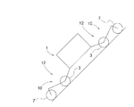
図1,2に示すように、作業車には、車両全体を支持する略矩形枠状の車両本体1と、複数(具体的には4個)の走行装置2と、複数の走行装置2の夫々に対応して設けられた複数の遊転輪3と、複数の走行装置2を各別に位置変更自在に車両本体1に支持する車体支持部としての屈折リンク機構10と、屈折リンク機構10を変更操作可能な駆動操作部としての油圧駆動式の駆動機構5と、駆動機構5に作動油を供給する作動油供給装置6とが備えられている。
As shown in FIGS. 1 and 2, the work vehicle includes a
複数の走行装置2は夫々、横軸芯周りで回転可能に支持された車輪7と、車輪7の軸支部8に内装された油圧モータ9とを備えている。各走行装置2は、油圧モータ9を作動させることにより、各別に車輪7を回転駆動することができる。
Each of the plurality of traveling
この実施形態で、車体の前後方向を定義するときは、車体進行方向に沿って定義し、車体の左右方向を定義するときは、機体進行方向視で見た状態で左右を定義する。すなわち、図1に符号(A)で示す方向が車体前後方向であり、図2に符号(B)で示す方向が車体左右方向である。 In this embodiment, the front-back direction of the vehicle body is defined along the vehicle body traveling direction, and the left-right direction of the vehicle body is defined when the vehicle body traveling direction is viewed. That is, the direction indicated by reference numeral (A) in FIG. 1 is the vehicle body front-rear direction, and the direction indicated by reference numeral (B) in FIG. 2 is the vehicle body left-right direction.
駆動機構5は、複数の屈折リンク機構10の姿勢を各別に変更可能である。複数の屈折リンク機構10夫々の中間屈折部11(図4参照)に自由回転自在に遊転輪3が支持されている。そして、1つの走行装置2と当該走行装置2に対応する1つの遊転輪3とにより1組の走行作動部12が構成され、1組の走行作動部12は1つの屈折リンク機構10によって姿勢変更可能に支持される。車両本体1の前後両側に夫々左右一対ずつ合計4組の走行作動部12が備えられる。従って、屈折リンク機構10、走行装置2及び遊転輪3の夫々が、車両本体1の前後両側に夫々左右一対ずつ備えられている。
The
車両本体1は、車両本体1の全周を囲うとともに、全体を支持する矩形枠状の支持フレーム13を備えている。作動油供給装置6は車両本体1の内部に収納して支持されている。詳述はしないが、作動油供給装置6には、車両に搭載されるエンジンにて駆動されるとともに、駆動機構5に向けて作動油を送り出す油圧ポンプ、油圧ポンプから駆動機構5に供給される作動油を制御する複数の油圧制御弁、作動油タンク等が備えられ、駆動機構5に対する作動油の給排あるいは流量の調節等を行う。
The
車両本体1の内部には、作動油供給装置6の動作を制御する制御装置15が備えられている。制御装置15の制御動作については詳述はしないが、図示しない手動入力装置にて入力される制御情報、あるいは、予め設定して記憶されている制御情報に基づいて、駆動機構5及び油圧モータ9に対する作動油の供給状態を制御する。
A
次に、走行装置2を車両本体1に支持するための支持構造について説明する。
複数(具体的には4つ)の走行装置2は、屈折リンク機構10を介して車両本体1に対して各別に昇降自在に支持されている。屈折リンク機構10は旋回機構16により縦軸芯周りで向き変更可能に車両本体1に支持されている。
Next, a support structure for supporting the traveling
A plurality of (specifically, four) traveling
屈折リンク機構10は、旋回機構16を介して縦軸芯Y周りで揺動自在に支持フレーム13に支持されている。旋回機構16には、支持フレーム13に連結されるとともに、屈折リンク機構10を揺動自在に支持する車体側支持部17(図3、図4参照)と、屈折リンク機構10を旋回操作させる旋回用油圧シリンダ(以下、旋回シリンダと称する)18とが備えられている。
The
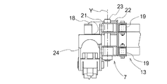
説明を加えると、図3,4,5,6に示すように、車体側支持部17は、支持フレーム13における横側箇所に備えられた上下一対の角筒状の前後向きフレーム体19に対して、横側外方から挟み込む状態で嵌め合い係合するとともに、取外し可能にボルト連結される連結部材20と、連結部材20の車体前後方向外方側箇所に位置する外方側枢支ブラケット21と、連結部材20の車体前後方向の内方側箇所に位置する内方側枢支ブラケット22と、外方側枢支ブラケット21に支持される縦向きの回動支軸23とを備え、回動支軸23の軸芯Y周りで回動自在に屈折リンク機構10を支持している。
3, the vehicle body
屈折リンク機構10には、上下方向の位置が固定された状態で且つ縦軸芯Y周りで回動自在に車体側支持部17に支持される基端部24と、一端部が基端部24の下部に横軸芯X1周りで揺動自在に支持された第1リンク25と、一端部が第1リンク25の他端部に横軸芯X2周りで揺動自在に支持され且つ他端部に走行装置2が支持された第2リンク26とが備えられている。
The
説明を加えると、基端部24は、平面視で矩形枠状に設けられ、車体横幅方向内方側に偏倚した箇所において、回動支軸23を介して縦軸芯Y周りで回動自在に、車体側支持部17の外方側枢支ブラケット21に支持されている。旋回シリンダ18は、一端部が、内方側枢支ブラケット22に回動自在に連結され、他端部が、基端部24における回動支軸23に対して横方向に位置ずれした箇所に回動自在に連結されている。
In addition, the
基端部24の左右両側部に亘って第1リンク25の一端側に備えられた支持軸27が回動自在に架設支持され、第1リンク25は基端部24の下部に対して支持軸27の軸芯周りで回動自在に連結されている。
A
図4に示すように、第1リンク25は、基端側アーム部25bと他端側アーム部25aとを有している。第1リンク25の一端側箇所には、斜め上外方に向けて延びる基端側アーム部25bが一体的に形成されている。第1リンク25の他端側箇所には、斜め上外方に向けて延びる他端側アーム部25aが一体的に形成されている。
As shown in FIG. 4, the
図3に示すように、第2リンク26は、左右一対の帯板状の板体26a,26bを備えて平面視で二股状に形成されている。第2リンク26の第1リンク25に対する連結箇所は一対の板体26a,26bが間隔をあけている。一対の板体26a,26bで挟まれた領域に、第1リンク25と連結するための連結支軸28が回動自在に支持されている。第2リンク26の第1リンク25に対する連結箇所とは反対側の揺動側端部には走行装置2が支持されている。図4に示すように、第2リンク26の揺動側端部は車両本体1から離れる方向に略L字状に延びるL字状延設部26Aが形成され、L字状延設部26Aの延設側端部に走行装置2が支持されている。
As shown in FIG. 3, the
複数(4個)の屈折リンク機構10の夫々に対応して駆動機構5が備えられている。図1,4に示すように、駆動機構5には、車両本体1に対する第1リンク25の揺動姿勢を変更可能な第1油圧シリンダ29と、第1リンク25に対する第2リンク26の揺動姿勢を変更可能な第2油圧シリンダ30とが備えられている。第1油圧シリンダ29及び第2油圧シリンダ30は、夫々、第1リンク25の近傍に集約して配置されている。
The
第1リンク25、第1油圧シリンダ29及び第2油圧シリンダ30が、平面視において、第2リンク26の一対の板体26a,26bの間に位置する状態で配備されている。図3,4に示すように、第1油圧シリンダ29は、第1リンク25に対して車体前後方向内方側に位置して、第1リンク25の長手方向に沿うように設けられている。第1油圧シリンダ29の一端部が円弧状の第1連動部材31を介して基端部24の下部に連動連結されている。第1油圧シリンダ29の一端部は、別の第2連動部材32を介して第1リンク25の基端側箇所に連動連結されている。第1連動部材31及び第2連動部材32は、両側端部が夫々、相対回動可能に枢支連結されている。第1油圧シリンダ29の他端部は、第1リンク25に一体的に形成された他端側アーム部25aに連動連結されている。
The
第2油圧シリンダ30は、第1油圧シリンダ29とは反対側、すなわち、第1リンク25に対して車体前後方向外方側に位置して、第1リンク25の長手方向に略沿うように設けられている。第2油圧シリンダ30の一端部が第1リンク25の基端側に一体的に形成された基端側アーム部25bに連動連結されている。第2油圧シリンダ30の他端部は、第3連動部材34を介して第2リンク26の一端側箇所に一体的に形成されたアーム部35に連動連結されている。第2油圧シリンダ30の他端部は、別の第4連動部材36を介して第1リンク25の揺動端側箇所にも連動連結されている。第3連動部材34及び第4連動部材36は、両側端部が夫々、相対回動可能に枢支連結されている。
The second
第2油圧シリンダ30の作動を停止した状態で第1油圧シリンダ29を伸縮操作すると、第1リンク25、第2リンク26及び走行装置2の夫々が、相対姿勢を一定に維持したまま一体的に、基端部24に対する枢支連結箇所の横軸芯X1周りで揺動する。第1油圧シリンダ29の作動を停止した状態で第2油圧シリンダ30を伸縮操作すると、第1リンク25の姿勢が一定に維持されたまま、第2リンク26及び走行装置2が、一体的に、第1リンク25と第2リンク26との連結箇所の横軸芯X2周りで揺動する。
When the first
複数(4つ)の屈折リンク機構10夫々の中間屈折部11に自由回転自在に遊転輪3が支持されている。図1,2に示すように、遊転輪3は走行装置2の車輪7と略同じ外径の車輪にて構成されている。図3に示すように、第1リンク25と第2リンク26とを枢支連結する連結支軸28が、第2リンク26よりも車体横幅方向外方側に突出するように延長形成されている。連結支軸28の延長突出箇所に遊転輪3が回動自在に支持されている。つまり、第1リンク25と第2リンク26とを枢支連結する連結支軸28が、遊転輪3の回動支軸を兼用する構成となっており、部材の兼用により構成の簡素化を図っている。
The
図3に示すように、旋回シリンダ18は、一端部が、内方側枢支ブラケット22に回動自在に連結され、他端部が、基端部24における回動支軸23に対して横方向に位置ずれした箇所に回動自在に連結されている。
As shown in FIG. 3, the swiveling
図7,8に示すように、屈折リンク機構10、走行装置2、遊転輪3、及び、駆動機構5の夫々が、一体的に、回動支軸23の軸芯Y周りで回動自在に外方側枢支ブラケット21に支持されている。そして、旋回シリンダ18を伸縮させることにより、それらが一体的に回動操作される。走行装置2が前後方向に向く直進状態から左旋回方向及び右旋回方向に夫々、約45度ずつ旋回操作させることができる。
As shown in FIGS. 7 and 8, each of the
前後向きフレーム体19に対する連結部材20のボルト連結を解除すると、旋回機構16、屈折リンク機構10、走行装置2、遊転輪3、及び、駆動機構5の夫々が、一体的に組付けられた状態で、車両本体1から取り外すことができる。又、前後向きフレーム体19に対して連結部材20をボルト連結することで、上記各装置が一体的に組付けられた状態で、車両本体1に取付けることができる。
When the bolt connection of the connecting
作動油供給装置6から複数の屈折リンク機構10夫々の第1油圧シリンダ29及び第2油圧シリンダ30に作動油が供給される。油圧制御弁により作動油の給排が行われて、第1油圧シリンダ29及び第2油圧シリンダ30を伸縮操作させることができる。油圧制御弁は制御装置15によって制御される。
The hydraulic oil is supplied from the hydraulic
又、油圧モータ9に対応する油圧制御弁により作動油の流量調整が行われることで、油圧モータ9すなわち車輪7の回転速度を変更することができる。油圧制御弁は、手動操作にて入力される制御情報あるいは予め設定記憶されている制御情報等に基づいて制御装置15によって制御される。
Moreover, the rotational speed of the
図1に示すように、この作業車は種々のセンサを備える。具体的には、それぞれの第1油圧シリンダ29に設けられた第一キャップ側圧力センサS1及び第一ヘッド側(反キャップ側)圧力センサS2、それぞれの第2油圧シリンダ30に設けられた第二キャップ側圧力センサS3及び第二ヘッド側(反キャップ側)圧力センサS4を備える。第一キャップ側圧力センサS1は、第1油圧シリンダ29のキャップ側室の油圧を検出する。第一ヘッド側圧力センサS2は、第1油圧シリンダ29のヘッド側室の油圧を検出する。第二キャップ側圧力センサS3は、第2油圧シリンダ30のキャップ側室の油圧を検出する。第二ヘッド側圧力センサS4は、第2油圧シリンダ30のヘッド側室の油圧を検出する。又、図示はしていないが、上記各油圧シリンダ18,29,30は、伸縮ストローク量を検出可能なストロークセンサを内装しており、操作状態を制御装置15にフィードバックするように構成されている。
As shown in FIG. 1, this work vehicle includes various sensors. Specifically, the first cap side pressure sensor S1 and the first head side (opposite cap side) pressure sensor S2 provided in each first
なお、各圧力センサS1,S2,S3,S4の取り付け位置は上記した位置に限られるものではない。各圧力センサS1,S2,S3,S4は、対応するキャップ側室又はヘッド側室の油圧を検出(推定)可能であればよく、弁機構から対応するキャップ側室又はヘッド側室の間の配管に設けられてもよい。 The mounting positions of the pressure sensors S1, S2, S3, S4 are not limited to the above positions. Each pressure sensor S1, S2, S3, S4 is only required to be able to detect (estimate) the oil pressure in the corresponding cap side chamber or head side chamber, and is provided in the pipe between the valve mechanism and the corresponding cap side chamber or head side chamber. Good.
これらのセンサの検出結果に基づいて、車両本体1を支持するために必要な力が算出され、その結果に基づいて、それぞれの第1油圧シリンダ29及び第2油圧シリンダ30への作動油の供給が制御される。具体的には、第一キャップ側圧力センサS1の検出値と第一ヘッド側圧力センサS2の検出値とに基づき、第1油圧シリンダ29のキャップ側室とヘッド側室との差圧から、第1油圧シリンダ29のシリンダ推力が算出される。また、第二キャップ側圧力センサS3の検出値と第二ヘッド側圧力センサS4の検出値とに基づき、第1油圧シリンダ29と同様に、第2油圧シリンダ30のシリンダ推力が算出される。
The force required to support the
車両本体1には、例えば、三軸加速度センサ等からなる加速度センサS5が備えられている。加速度センサS5の検出結果に基づき、車両本体1の前後左右の傾きが検知され、その結果に基づいて車両本体1の姿勢が制御される。つまり、車両本体1の姿勢が目標の姿勢となるよう、それぞれの第1油圧シリンダ29及び第2油圧シリンダ30への作動油の供給が制御される。
The
走行装置2には、車輪7の回転速度を検出する回転センサS6を備える。回転センサS6にて算出された車輪7の回転速度に基づいて、車輪7の回転速度が目標の値となるように、油圧モータ9への作動油の供給が制御される。
The traveling
上述したように、本実施形態の作業車は、屈折リンク機構10を介して走行装置2を支持する構成とし、油圧駆動式の駆動機構5としての油圧シリンダ29,30により、屈折リンク機構10の姿勢を変更操作する構成であり、しかも、走行駆動も油圧モータにて行う構成であるから、水分や細かな塵埃等による影響を受け難く、農作業に適したものになる。
As described above, the work vehicle of the present embodiment is configured to support the traveling
このような構成の作業車の使用例として、次のような走行形態がある。
〈平坦地での走行形態〉
平坦地を走行する場合、図9,10,11に示すように、複数種の異なる走行形態のいずれかにて走行することができる。すなわち、図9に示すように、4個の走行装置2(具体的には車輪7)が全て接地し且つ4個の遊転輪3が全て地面から浮上する4輪走行状態と、図10に示すように、車体前後方向の一方側に位置する走行装置2(車輪7)が浮上し且つその走行装置2(車輪7)に対応する遊転輪3が接地するとともに、車体前後方向の他方側に位置する走行装置2(車輪7)が接地し且つその走行装置2(車輪7)に対応する遊転輪3が浮上する2輪走行状態である。
The following traveling modes are examples of use of the work vehicle having such a configuration.
<Running form on flat ground>
When traveling on a flat ground, as shown in FIGS. 9, 10, and 11, it is possible to travel in any of a plurality of different traveling modes. That is, as shown in FIG. 9, a four-wheel traveling state in which all four traveling devices 2 (specifically, wheels 7) are in contact with the ground and four
2輪走行状態として、走行装置2(車輪7)と遊転輪3との関係が車体前後方向で反対となる状態、すなわち、図11に示すように、車体前後方向一方側に位置する走行装置2(車輪7)が接地し且つその走行装置2(車輪7)に対応する遊転輪3が地面から浮上するとともに、車体前後方向他方側に位置する走行装置2(車輪7)が浮上し且つその走行装置2(車輪7)に対応する遊転輪3が接地する状態もある。
In the two-wheel traveling state, the traveling device 2 (wheels 7) and the
説明を加えると、屈折リンク機構10は、4組の走行作動部12の夫々において、走行装置2(車輪7)が接地し且つそれに対応する遊転輪3が地面から浮上する走行状態と、遊転輪3が接地し且つそれに対応する走行装置2(車輪7)が地面から浮上する自由移動状態とに切り換え可能に構成されている。
In addition, in the
上記4輪走行状態では、4組の走行作動部12が全て走行状態に設定され、上記2輪走行状態では、4個の走行作動部12のうちの車体前後方向一方側の2組の走行作動部12が走行状態に設定され、且つ、反対側の2組の走行作動部12が自由移動状態に設定される。
In the four-wheel running state, all four sets of the running
又、上記したような4輪走行状態と2輪走行状態以外にも、例えば、4個の走行作動部12のうちの3個の走行作動部12が走行状態となり、他の1個の走行作動部12が自由移動状態となる一部走行状態に切り換えることも可能である。これにより、3個の走行作動部12によって安定的に接地しながら、1つの走行作動部12を例えば、段差の上側にまで延ばす等の操作を行うことができる。それ以外にも、一部走行状態として、4個の走行作動部12のうちの3個の走行作動部12が自由移動状態となり、他の1個の走行作動部12を走行状態に切り換えることも可能である。
In addition to the four-wheel traveling state and the two-wheel traveling state as described above, for example, three traveling
要するに、駆動機構5が、4個の走行作動部12のうちの全てのものが走行状態となる全部走行状態と、4個の走行作動部12のうちの少なくとも一つが走行状態となり、残りのものが自由移動状態となる一部走行状態とに切り換え可能である。
In short, the
上記したような走行形態の他、図12に示すように、4組全ての走行作動部12を全て自由移動状態に切り換えて使用することもできる。この場合には、駆動走行することはできないが、手動で楽に押し移動させることができる。
In addition to the above-described traveling mode, as shown in FIG. 12, all four sets of traveling
この作業車では、上記したような平坦面での走行の他にも、独特の使用形態として、次のような形態で使用することが可能である。 In addition to traveling on a flat surface as described above, this work vehicle can be used in the following forms as a unique form of use.
〈2脚直立形態〉
車両本体1を大きく傾斜させて、走行装置2を高所に乗せることができる。
すなわち、図13に示すように、車体前後方向一方側の2組の走行作動部12における走行装置2と遊転輪3とを全て接地させている状態で、車体前後方向他方側の2組の走行作動部12を支持する屈折リンク機構10を用いて、他方側が上昇するように車両本体1を大きく傾斜させる。そして、車両本体1の重心位置Wが一方側の2組の走行作動部12による接地幅L内に位置するまで傾斜すると、他方側の2組の走行作動部12を支持する屈折リンク機構10を大きく伸長させて、走行装置2を高い所にある地面に乗せることができる。
<2 legs upright form>
The
That is, as shown in FIG. 13, in a state in which the traveling
この2脚直立形態においては、高い所へ乗り上げる形態以外にも、図14,15に示すように、他の物体を持ち上げる動作も行うことが可能である。すなわち、上記したように、車体前後方向一方側の2組の走行作動部12における走行装置2と遊転輪3とを接地させている状態で車両本体1を大きく傾斜させ、車両本体1の重心位置Wが一方側の2組の走行作動部12による接地幅L内に位置するまで傾斜させる。さらに、車体前後方向他方側の2組の走行作動部12について、左右両側の走行作動部12が互いに近づくように旋回作動させる。車体前後方向他方側の2組の走行作動部12における夫々の走行装置2によって、搬送対象となる物体Mを把持して持ち上げる。物体Mを把持している状態で、車体前後方向一方側の2組の走行作動部12にて車両本体1の姿勢を維持しながら走行して移動することができ、物体Mの搬送を行える。
In this two-leg upright form, in addition to the form of climbing to a high place, as shown in FIGS. 14 and 15, it is possible to perform an operation of lifting another object. That is, as described above, the
〈法面走行形態〉
図16に示すように、4組全ての走行作動部12について、屈折リンク機構10の姿勢を、走行装置2及び遊転輪3の夫々が車体前後方向外端部よりも車体前後方向外側に位置する伸展姿勢に変更操作する。走行装置2と遊転輪3とが全て接地している状態で、第1リンク25及び第2リンク26をできるだけ水平姿勢に近付けて車両本体1の高さを低い位置に下げる。このような状態で、法面を乗り上がりながら走行する。この走行形態では、車体前後方向に沿う接地幅が広くなり、大きく傾斜している法面であっても、転倒することなく安定した状態で走行することができる。
<Slope running form>
As shown in FIG. 16, the postures of the
〈段差乗り越え形態〉
4組の走行作動部12のうちの3組の走行作動部12における走行装置2と遊転輪3とが全て接地させて、車両本体1を地面に安定的に接地支持している状態で、残り1組の走行作動部12を支持する屈折リンク機構10を大きく伸長させて、例えば、図13に示すように、走行装置2を段差の上部面に乗せる。そして、各組の走行作動部12における屈折リンク機構10を伸縮させながら、1組ずつ走行作動部12を段差の上部面に乗り移りながら移動することで、段差を乗り越えることが可能となる。図13では、段差が高い場合を示しているが、低い段差であれば、車両本体1が乗り上がることができる。
<Step over step>
In a state where the traveling
〈跨ぎ走行形態〉
図17に示すように、4組の走行作動部12の全てについて、屈折リンク機構10を大きく伸長させて車両本体1を接地面から大きく上昇させる。例えば、畝を跨いだ状態で車両本体1を畝の上方に位置させた状態で作業を行うことができる。畝に植えられている作物が成長しても、作物の上方側から例えば、薬剤散布や収穫作業等を行うことができる。
<Crossover traveling mode>
As shown in FIG. 17, the
尚、詳細な説明は省略するが、上記したような各種の形態で走行する場合、手動操作にて入力される制御情報あるいは予め設定記憶されている制御情報等に基づいて、指令された内容に対応する形態となるように、制御装置15が各油圧シリンダ18,29,30及び各油圧モータ9の作動を制御する。
Although detailed description is omitted, when traveling in various forms as described above, based on the control information input by manual operation or the control information preset and stored, the command contents are changed. The
〔別実施形態〕
(1)上記実施形態では、走行装置2が油圧モータ9により駆動される構成としたが、この構成に代えて、例えば、車両に搭載されたエンジンの動力がチェーン伝動機構等の機械式伝動機構を介して車輪7に供給される構成でもよい。
[Another embodiment]
(1) In the above embodiment, the traveling
(2)上記実施形態では、走行装置2が1つの車輪7を備える構成としたが、この構成に代えて、走行装置2として、複数の輪体にクローラベルトが巻回されたクローラ走行装置を備える構成としてもよい。
(2) In the above embodiment, the traveling
(3)上記実施形態では、走行作動部12が、車両本体1の前後両側部において左右一対ずつ備えられる構成としたが、走行作動部12が3個備えられる構成、あるいは、走行作動部12が5個以上備えられる構成であってもよい。
(3) In the above-described embodiment, the traveling
(4)上記実施形態では、旋回機構16に、屈折リンク機構10の全体を旋回操作可能な旋回用油圧シリンダ18が備えられる構成としたが、旋回操作を電動モータや油圧モータにより行うものでもよい。
(4) In the above embodiment, the
本発明は、凹凸の多い路面を走行するのに適した作業車に適用できる。 INDUSTRIAL APPLICABILITY The present invention can be applied to a work vehicle suitable for traveling on a road surface having many irregularities.
1 車両本体
2 走行装置
5 駆動機構
10 屈折リンク機構
16 旋回機構
25 第1リンク
26 第2リンク
29 第1油圧シリンダ
30 第2油圧シリンダ
31 第1連動部材
32 第2連動部材
34 第3連動部材
36 第4連動部材
1
Claims (3)
走行駆動する複数の走行装置と、
複数の前記走行装置を各別に昇降自在に前記車両本体に支持する複数の屈折リンク機構と、
複数の前記屈折リンク機構の姿勢を各別に変更可能な駆動機構とが備えられ、
前記屈折リンク機構は、一端側が前記車両本体に横軸芯周りで揺動自在に枢支連結された第1リンクと、一端側が前記第1リンクの他端側に横軸芯周りで揺動自在に枢支連結され且つ他端側に前記走行装置が支持された第2リンクとを有し、
前記駆動機構は、前記車両本体に対する前記第1リンクの揺動姿勢を変更可能な第1油圧シリンダと、前記第1リンクに対する前記第2リンクの揺動姿勢を変更可能な第2油圧シリンダとを有し、
前記第1油圧シリンダ及び前記第2油圧シリンダの夫々が、前記第1リンクの近傍に集約して配置され、
前記第1油圧シリンダの一端側が、前記車両本体側の支持部材に第1連動部材を介して枢支連結されるとともに、前記第1リンクの一端側に第2連動部材を介して枢支連結され、前記第1油圧シリンダの他端側が、前記第1リンクの他端側と枢支連結され、 前記第2油圧シリンダの一端側が、前記第1リンクの一端側と枢支連結され、前記第2油圧シリンダの他端側が、前記第2リンクの一端側に第3連動部材を介して枢支連結されるとともに、前記第1リンクの他端側に第4連動部材を介して枢支連結されている作業車。 The vehicle body,
A plurality of traveling devices for traveling and driving,
A plurality of refraction link mechanisms that individually support the plurality of traveling devices so that they can be raised and lowered, respectively,
And a drive mechanism capable of individually changing the postures of the plurality of refraction link mechanisms,
The bending link mechanism has a first link pivotally connected to the vehicle body at one end side so as to be swingable about a horizontal axis core, and one end side is swingable about the horizontal axis to the other end side of the first link. A second link pivotally connected to the second end and the traveling device being supported on the other end side,
The drive mechanism includes a first hydraulic cylinder that can change the swinging posture of the first link with respect to the vehicle body, and a second hydraulic cylinder that can change the swinging posture of the second link with respect to the first link. Have,
Each of the first hydraulic cylinder and the second hydraulic cylinder is collectively arranged near the first link,
One end side of the first hydraulic cylinder is pivotally connected to the support member on the vehicle body side via a first interlocking member, and is pivotally connected to one end side of the first link via a second interlocking member. The other end of the first hydraulic cylinder is pivotally connected to the other end of the first link, and the one end of the second hydraulic cylinder is pivotally connected to one end of the first link. The other end of the hydraulic cylinder is pivotally connected to one end of the second link via a third interlocking member, and is pivotally connected to the other end of the first link via a fourth interlocking member. Working vehicle.
Priority Applications (5)
| Application Number | Priority Date | Filing Date | Title |
|---|---|---|---|
| JP2017066388A JP6701112B2 (en) | 2017-03-29 | 2017-03-29 | Work vehicle |
| EP18777724.8A EP3604092B1 (en) | 2017-03-29 | 2018-03-28 | Work vehicle |
| PCT/JP2018/012710 WO2018181460A1 (en) | 2017-03-29 | 2018-03-28 | Work vehicle |
| CN201880023027.9A CN110494349B (en) | 2017-03-29 | 2018-03-28 | Working vehicle |
| US16/496,151 US11260922B2 (en) | 2017-03-29 | 2018-03-28 | Work vehicle |
Applications Claiming Priority (1)
| Application Number | Priority Date | Filing Date | Title |
|---|---|---|---|
| JP2017066388A JP6701112B2 (en) | 2017-03-29 | 2017-03-29 | Work vehicle |
Publications (2)
| Publication Number | Publication Date |
|---|---|
| JP2018167691A JP2018167691A (en) | 2018-11-01 |
| JP6701112B2 true JP6701112B2 (en) | 2020-05-27 |
Family
ID=64019886
Family Applications (1)
| Application Number | Title | Priority Date | Filing Date |
|---|---|---|---|
| JP2017066388A Active JP6701112B2 (en) | 2017-03-29 | 2017-03-29 | Work vehicle |
Country Status (1)
| Country | Link |
|---|---|
| JP (1) | JP6701112B2 (en) |
Family Cites Families (3)
| Publication number | Priority date | Publication date | Assignee | Title |
|---|---|---|---|---|
| US4558758A (en) * | 1983-12-02 | 1985-12-17 | Erwin Littman | Prime mover |
| JP4797775B2 (en) * | 2006-04-24 | 2011-10-19 | 株式会社日立製作所 | Biped type moving mechanism |
| JP2009096335A (en) * | 2007-10-17 | 2009-05-07 | Nsk Ltd | Legged robot |
-
2017
- 2017-03-29 JP JP2017066388A patent/JP6701112B2/en active Active
Also Published As
| Publication number | Publication date |
|---|---|
| JP2018167691A (en) | 2018-11-01 |
Similar Documents
| Publication | Publication Date | Title |
|---|---|---|
| WO2018181459A1 (en) | Work vehicle | |
| US11235824B2 (en) | Work vehicle | |
| JP6758278B2 (en) | Work vehicle | |
| CN111247055B (en) | Working vehicle | |
| CN110494349B (en) | Working vehicle | |
| JP6745750B2 (en) | Work vehicle | |
| WO2020004024A1 (en) | Working vehicle | |
| JP6934455B2 (en) | Work platform | |
| JP6899801B2 (en) | Work platform | |
| JP7117989B2 (en) | work vehicle | |
| JP6899799B2 (en) | Work platform | |
| JP6843040B2 (en) | Work platform | |
| JP6758277B2 (en) | Work vehicle | |
| JP6937725B2 (en) | Work platform | |
| JP6701111B2 (en) | Work vehicle | |
| JP6701112B2 (en) | Work vehicle | |
| JP6739387B2 (en) | Work vehicle | |
| JP6745751B2 (en) | Work vehicle | |
| JP6832841B2 (en) | Work vehicle | |
| JP6899800B2 (en) | Work platform | |
| WO2019131573A1 (en) | Work vehicle |
Legal Events
| Date | Code | Title | Description |
|---|---|---|---|
| A621 | Written request for application examination |
Free format text: JAPANESE INTERMEDIATE CODE: A621 Effective date: 20190626 |
|
| TRDD | Decision of grant or rejection written | ||
| A01 | Written decision to grant a patent or to grant a registration (utility model) |
Free format text: JAPANESE INTERMEDIATE CODE: A01 Effective date: 20200407 |
|
| A61 | First payment of annual fees (during grant procedure) |
Free format text: JAPANESE INTERMEDIATE CODE: A61 Effective date: 20200501 |
|
| R150 | Certificate of patent or registration of utility model |
Ref document number: 6701112 Country of ref document: JP Free format text: JAPANESE INTERMEDIATE CODE: R150 |