JP6700794B2 - Imprint material discharge device - Google Patents
Imprint material discharge device Download PDFInfo
- Publication number
- JP6700794B2 JP6700794B2 JP2016002753A JP2016002753A JP6700794B2 JP 6700794 B2 JP6700794 B2 JP 6700794B2 JP 2016002753 A JP2016002753 A JP 2016002753A JP 2016002753 A JP2016002753 A JP 2016002753A JP 6700794 B2 JP6700794 B2 JP 6700794B2
- Authority
- JP
- Japan
- Prior art keywords
- imprint material
- opening
- imprint
- discharge
- region
- Prior art date
- Legal status (The legal status is an assumption and is not a legal conclusion. Google has not performed a legal analysis and makes no representation as to the accuracy of the status listed.)
- Active
Links
Images


Classifications
-
- B—PERFORMING OPERATIONS; TRANSPORTING
- B41—PRINTING; LINING MACHINES; TYPEWRITERS; STAMPS
- B41J—TYPEWRITERS; SELECTIVE PRINTING MECHANISMS, i.e. MECHANISMS PRINTING OTHERWISE THAN FROM A FORME; CORRECTION OF TYPOGRAPHICAL ERRORS
- B41J2/00—Typewriters or selective printing mechanisms characterised by the printing or marking process for which they are designed
- B41J2/005—Typewriters or selective printing mechanisms characterised by the printing or marking process for which they are designed characterised by bringing liquid or particles selectively into contact with a printing material
- B41J2/01—Ink jet
- B41J2/17—Ink jet characterised by ink handling
- B41J2/175—Ink supply systems ; Circuit parts therefor
- B41J2/17563—Ink filters
-
- B—PERFORMING OPERATIONS; TRANSPORTING
- B41—PRINTING; LINING MACHINES; TYPEWRITERS; STAMPS
- B41J—TYPEWRITERS; SELECTIVE PRINTING MECHANISMS, i.e. MECHANISMS PRINTING OTHERWISE THAN FROM A FORME; CORRECTION OF TYPOGRAPHICAL ERRORS
- B41J2/00—Typewriters or selective printing mechanisms characterised by the printing or marking process for which they are designed
- B41J2/005—Typewriters or selective printing mechanisms characterised by the printing or marking process for which they are designed characterised by bringing liquid or particles selectively into contact with a printing material
- B41J2/01—Ink jet
- B41J2/135—Nozzles
- B41J2/14—Structure thereof only for on-demand ink jet heads
Landscapes
- Shaping Of Tube Ends By Bending Or Straightening (AREA)
- Ink Jet (AREA)
- Exposure Of Semiconductors, Excluding Electron Or Ion Beam Exposure (AREA)
- Particle Formation And Scattering Control In Inkjet Printers (AREA)
- Coating Apparatus (AREA)
Description
本発明は、インプリント材を吐出するインプリント材吐出装置に関する。 The present invention relates to an imprint material discharging device that discharges an imprint material.
半導体デバイス等の製造プロセスにおいて、基板上のインプリント材に対してパターンが形成されたモールドを接触させ、インプリント材にモールドの形状を転写してパターンを形成する、所謂インプリント技術が知られている。特許文献1には、インプリント材を基板上に吐出するインプリント材吐出装置として、インクジェットヘッドを用いた吐出装置が記載されている。
In the manufacturing process of semiconductor devices and the like, a so-called imprint technique is known in which a pattern-formed mold is brought into contact with an imprint material on a substrate, and the shape of the mold is transferred to the imprint material to form the pattern. ing.
特許文献1に記載の吐出装置のインクジェットヘッドは、インプリント材を基板上に吐出するエネルギーを発生するエネルギー発生素子を有している。このような吐出装置において、インプリント材に異物が含まれていると、インプリント材にモールドを接触させた際に良好なパターンを形成できない場合がある。そこで、特許文献1に記載の吐出装置では、フィルタによって異物を除去したインプリント材を収容部へと供給している。
The inkjet head of the ejection device described in
本発明者らの検討によれば、特許文献1に記載のような吐出装置において、以下のような課題があることが分かった。例えば、インプリント材の材料や、或いはインプリント材を収容した状態でインプリント材収容部を長期間放置することにより、インプリント材の収容部内において、インプリント材の一部が経時変化によってゲル化する可能性がある。また、収容部内から発生する異物によってインプリント材が汚染する可能性がある。このような状態でインプリント材を基板上に吐出すると、インプリント材に接触させるモールドが破損したり、インプリント材のパターニング精度が低下したりする場合がある。
According to the study by the present inventors, it has been found that the discharge device described in
特許文献1に記載の方法によれば、インプリント材が収容部に入る前にフィルタを通るので、収容部に入った時点では異物等が除去されている。しかし、上述のように、収容部内で発生した異物や、インプリント材の経時変化には、対応することが困難である。
According to the method described in
また、本発明者らの検討によると、上述のようにインプリント材の収容部内で発生する異物は、大きさが数十nm程度と小さなものである。このような異物を除去可能な開口径の小さいフィルタをインプリント材の通路に設けると、フィルタでの流路抵抗(圧力損失)の影響によって吐出部材へのインプリント材の供給が遅くなり、インプリント材の吐出に影響が出ることがあった。 Further, according to the study by the present inventors, as described above, the foreign matter generated in the accommodating portion of the imprint material is as small as several tens nm. If a filter with a small opening diameter capable of removing such foreign matter is provided in the passage of the imprint material, the supply of the imprint material to the ejection member is delayed due to the influence of the flow path resistance (pressure loss) in the filter, and The ejection of printing material was sometimes affected.
従って、本発明は、収容部内のインプリント材に発生する異物をフィルタで良好に除去しつつ、インプリント材を吐出部材から良好に吐出可能なインプリント材吐出装置を提供することを目的とする。 Therefore, it is an object of the present invention to provide an imprint material ejecting apparatus which can favorably eject the imprint material from the ejecting member while satisfactorily removing foreign matters generated in the imprint material in the accommodating portion with a filter. ..
上記課題は、以下の本発明によって解決される。即ち本発明は、モールドを接触させてパターンを形成するインプリント材を基板上に吐出するインプリント材吐出装置であって、前記インプリント材を収容する収容部を有する収容部材と、前記収容部に接続する通路と、前記インプリント材を吐出する吐出部材と、を有し、前記吐出部材は、前記インプリント材が流通する領域と、前記領域と連通し前記領域を流通する前記インプリント材が外部に吐出される開口である吐出口と、駆動によって前記領域を流通する前記インプリント材を前記吐出口から吐出させる圧電素子または発熱抵抗体と、を有し、前記領域は、前記吐出口と、前記圧電素子または発熱抵抗体との間の領域であって、前記吐出部材の内部の領域であり、前記通路は、前記収容部に収容されたインプリント材を前記通路の内部に供給するための、前記収容部に開口する第1の開口と、前記第1の開口から供給されたインプリント材を前記収容部に供給するための、前記収容部に開口する第2の開口とを有し、前記通路の前記第1の開口と前記第2の開口との間には前記インプリント材をろ過するフィルタがあり、前記第1の開口から前記通路の内部に供給されたインプリント材は、前記領域を介さずに、前記第2の開口から前記収容部に供給され、前記収容部材と前記通路と前記吐出部材とが一体となったカートリッジ形態の吐出装置である。 The above problems can be solved by the present invention described below. That is, the present invention is an imprinting material ejecting apparatus for ejecting an imprinting material that contacts a mold to form a pattern onto a substrate, the accommodating member having an accommodating portion that accommodates the imprinting material, and the accommodating portion. And a discharge member configured to discharge the imprint material, the discharge member including a region in which the imprint material flows, and the imprint material communicating with the region and flowing in the region. Has a discharge port that is a discharge port to the outside, and a piezoelectric element or a heating resistor that discharges the imprint material flowing in the region from the discharge port by driving, and the region has the discharge port. And an area between the piezoelectric element or the heating resistor and an area inside the ejection member, and the passage supplies the imprint material accommodated in the accommodation portion to the inside of the passage. A first opening that opens to the storage section, and a second opening that opens to the storage section for supplying the imprint material supplied from the first opening to the storage section. A filter for filtering the imprint material is provided between the first opening and the second opening of the passage, and the imprint material supplied from the first opening into the passage is A cartridge-type ejection device which is supplied to the accommodation portion through the second opening without passing through the region and in which the accommodation member, the passage, and the ejection member are integrated .
本発明によれば、収容部内のインプリント材に発生する異物をフィルタで良好に除去しつつ、インプリント材を吐出部材から良好に吐出可能なインプリント材吐出装置を提供することができる。 According to the present invention, it is possible to provide an imprint material ejecting apparatus which can favorably eject the imprint material from the ejecting member while satisfactorily removing foreign matters generated in the imprint material in the accommodating portion with the filter.
以下、本発明を実施するための形態を、図面を用いながら説明する。 Hereinafter, modes for carrying out the present invention will be described with reference to the drawings.
図1に、インプリント装置の構成の一例を示す。ここでは、インプリント材として紫外線硬化型樹脂を用い、紫外線硬化型樹脂を紫外線の照射によって硬化させる装置の例で説明するが、インプリント材の材料や硬化の方法はこれに限られない。例えば、光照射装置によって紫外線以外の波長の光を照射して光硬化型樹脂を硬化させてもよいし、熱硬化型の樹脂を用いて熱で硬化させてもよい。 FIG. 1 shows an example of the configuration of the imprint apparatus. Here, an example of an apparatus in which an ultraviolet curable resin is used as the imprint material and the ultraviolet curable resin is cured by irradiation of ultraviolet rays will be described, but the material of the imprint material and the curing method are not limited to this. For example, the light irradiation device may irradiate light having a wavelength other than ultraviolet light to cure the photo-curable resin, or a thermosetting resin may be used to thermally cure the resin.
図1に示すインプリント装置100は、インプリント材吐出装置10と、モールド1とを有する。モールド1を有するインプリント装置100とインプリント材吐出装置10とは別体であってもよい。即ち、インプリント材吐出装置10によってインプリント材を吐出し、インプリント材吐出装置10とは別のインプリント装置100が有するモールドによってインプリントを行ってもよい。
The
インプリント材吐出装置10は、インプリント材の吐出部材11と、インプリント材を収容する収容部を有する収容部材12と、圧力制御部材13とを有する。ステージ6上には基板4が設置されており、吐出部材11から基板4上にインプリント材8が吐出される。基板上に吐出されたインプリント材8には、モールド1を接触させ、この状態でインプリント材8に紫外線照射装置7から紫外線を照射し、インプリント材8を硬化させる。モールド1には微細な凹凸状のパターン等が形成されており、モールド1を上方に移動させると、インプリント材にはモールドのパターンが転写された状態となっている。このようにして、インプリント材にパターンを形成する。
The imprint
ステージ6は、基板4を保持しながらベースフレーム5上を移動可能である。モールド1を上下駆動させるモールド駆動機構2は、構造体3に保持され、モールド1を基板4に近接させ、モールド1をインプリント材8に接触させることが可能である。モールド1の上方には紫外線照射装置7があり、モールド1を介してインプリント材8に紫外線9を照射する。紫外線9は、例えばi線やg線を発生するハロゲンランプ等の光源であってもよい。また、紫外線照射装置7は光源が発生した光を集光成形する機能を有していてもよい。
The
インプリント装置100を用いたインプリント動作をより詳細に説明する。まず、基板4をステージ6に搭載する。基板4は、ステージ6によってインプリント材吐出装置10の吐出部材11の下方に移動させられる。そしてステージ6を移動させながら吐出部材11からインプリント材8を基板4上に吐出する。
The imprint operation using the
次に、ステージ6によって、基板4のインプリント材8を吐出した部分を、モールド1の下方に移動させる。さらに、モールド1をモールド駆動機構2により降下させて、モールド1と基板4とが近接した状態とする。その状態で、アライメントスコープ等によりモールド1上のアライメントマークと基板上のアライメントマークとを重ね合わせ、両者の相対位置調整をおこなう。
Next, the portion of the
相対位置の調整後、モールド駆動機構2によりモールド1を下方(基板4の方向)にさらに降下させ、インプリント材8にモールド1を接触させる。その後、紫外線照射装置7から紫外線9を照射し、モールド1を透過した紫外線9をインプリント材8に照射する。この結果、インプリント材8の光硬化反応が発生し、インプリント材8が硬化する。
After adjusting the relative position, the
最後に、硬化したインプリント材8から、モールド駆動機構2によってモールド1を剥離させる。以上のような工程で、基板4上にパターン(パターニングされたインプリント材)を形成することができる。半導体の製造に用いるインプリント装置は、基板4上の全ての領域にパターンを形成する場合があるが、この場合には基板に対して領域を変えながら一連のインプリント動作を繰り返す。
Finally, the
次に、インプリント材吐出装置の説明を行う。図2に、インプリント材吐出装置10の模式図を示す。インプリント材吐出装置10は、主に吐出部材11、収容部材12、圧力制御部材13で構成されている。収容部材12の内部には、収容部内部の空間を分離する分離膜14が設けられている。分離膜14は、インプリント材と後述する充填液とを分離する膜であり、可撓性であることが好ましい。分離膜14の厚みは10μm以上200μm以下であることが好ましい。分離膜14は、液体及び気体の透過性が低い材料で形成することが好ましく、例えばアルミニウムの多層フィルムで形成することができる。分離膜14で形成された空間のうち、吐出部材11と連通している側の空間には、インプリント材が充填されている。吐出部材11は、インプリント材を吐出するためのエネルギーを発生するエネルギー発生素子を有する。吐出部材11の拡大図を、図3に示す。吐出部材11は、エネルギー発生素子29を有する。また、吐出部材11は、インプリント材を吐出するための吐出口32と、エネルギー発生素子29と吐出口32との間の領域33とを有する。エネルギー発生素子29としては圧電素子や発熱抵抗体が挙げられる。インプリント材として樹脂を多く含むものがよく用いられることから、エネルギー発生素子として圧電素子を用いることが好ましい。エネルギー発生素子29をコントローラーで制御することで、エネルギー発生素子29と吐出口32との間の領域33のインプリント材8が、吐出口32から基板上に吐出される。吐出部材11はインクジェットヘッド等で用いられるような液体吐出ヘッドであることが好ましい。他にも、制御弁等を用いて液体の供給と停止を制御する吐出部材を用いることもできる。
Next, the imprint material discharging device will be described. FIG. 2 shows a schematic diagram of the imprint
収容部材12は、インプリント材が収容されている収容部15と、収容部15と分離膜14を挟んで反対側の空間であり、かつ吐出部材11と連通していない空間である充填液部16とで構成されている。充填液部16は充填液で充填されており、連通部17を介して圧力制御部材13と連通している。圧力制御部材13は、充填液タンク、配管、圧力センサー、ポンプ、バルブ等から構成されている。圧力センサー、ポンプ、バルブは、充填液部内の充填液の圧力を制御している。圧力制御部材13で充填液の圧力を制御することで、分離膜14を介して収容部15内のインプリント材の圧力を制御することができる。これにより、吐出部材11における気液界面(メニスカス)の形状を安定化させ、再現性のよいインプリント材の吐出を行うことができる。
The
吐出部材11からインプリント材8の吐出を繰り返すと、収容部15内部のインプリント材が消費されて減少し、分離膜14が変形する。分離膜14の変形に伴い、圧力制御部材13によって充填液タンクから充填液部16に充填液が補充され、充填液部16が充填液で充填される。
When the discharge of the
インプリント装置に用いるインプリント材は、異物(微小パーティクル)や金属イオンをなるべく含まず、基板に塗布されるまでその性質を保つことが求められる。本発明では、インプリント材の吐出を繰り返して収容部15の容積が減少していき、最終的にインプリント材が全て消費されるまでの期間において、インプリント材を収容部15の外部から隔離した状態で貯留することができる。よって、外気との接触や圧力センサー等の機器類との接触がない為、初期に管理して封入したインプリント材に異物や金属イオンが増加することを抑制できる。
The imprint material used in the imprint apparatus is required to contain as little foreign matter (fine particles) and metal ions as possible and maintain its properties until it is applied to the substrate. In the present invention, the imprint material is separated from the outside of the
尚、収容部15は点滴袋のように分離膜として可撓性の膜を袋状にしたものでもよい。また、収容部15の内部に気液界面を設ける構成としてもよい。他にも、収容部15に大気連通口を連通させて大気解放型としてもよい。大気解放型とする場合、負圧制御を良好に行う為に、開閉を切り替える弁や、圧力を制御する機器を接続することが好ましい。
The
インクジェット記録装置の分野においては、吐出部材の吐出口におけるメニスカス形状安定のために、吐出部材の内部を一定範囲の負圧に維持する工夫がなされている。例えば、収容部内部に多孔質体を構成して液体を保持し、多孔質内部の毛管力を利用して負圧を形成する方法が知られている。他にも、バネのような機械要素と風船形状の膜との組み合わせで収容部内に負圧を形成する方法や、制御弁と空気圧を用いて負圧を制御する方法がある。本発明においても、これらの方法によって収容部の負圧を制御してもよい。 In the field of inkjet recording apparatuses, in order to stabilize the shape of the meniscus at the ejection port of the ejection member, the inside of the ejection member is maintained at a negative pressure within a certain range. For example, a method is known in which a porous body is formed inside the accommodating portion to hold a liquid, and a negative pressure is formed by utilizing a capillary force inside the porous body. Besides, there is a method of forming a negative pressure in the housing portion by a combination of a mechanical element such as a spring and a balloon-shaped membrane, and a method of controlling the negative pressure by using a control valve and air pressure. Also in the present invention, the negative pressure of the housing portion may be controlled by these methods.
本発明のインプリント材吐出装置は、収容部材の外に、収容部に接続する通路を設け、この通路の中にフィルタを配置するという構成である。図3に、本発明のインプリント材吐出装置の一例を示す。インプリント材吐出装置の収容部材の収容部15には、通路(通路を形成する通路形成部材28)が接続されている。通路形成部材28はインプリント材の通路を形成している部材であり、収容部15に開口する第1の開口20と第2の開口21とで収容部15と連通している。第1の開口20は収容部15の内部のインプリント材を通路の内部に供給する開口であり、第2の開口21は第1の開口20から供給したインプリント材を収容部15に供給する開口である。第1の開口20と第2の開口21を結ぶ通路には、ポンプ22と、インプリント材をろ過するフィルタ23とが配置されている。ポンプ22からの発塵によるインプリント材への異物発生の可能性を考慮すると、ポンプ22に対して、第1の開口20から第2の開口21へとインプリント材を流す際に下流側となる位置にフィルタ23を配置することが好ましい。ポンプ22は通路形成部材28の通路の内部に設けることが好ましいが、この通路の外部に設けてもよい。
The imprint material discharging device of the present invention is configured such that a passage connected to the containing portion is provided outside the containing member, and the filter is arranged in the passage. FIG. 3 shows an example of the imprint material discharging device of the present invention. A passage (
ポンプ22を駆動させると、収容部15内に収容されたインプリント材が第1の開口20から供給(吸引)される。第1の開口20から供給されたインプリント材は、通路の内部のフィルタ23を通過してろ過された後に、第2の開口21を経由して収容部15内に戻る。そして再び第1の開口20から供給される。即ち、収容部15内のインプリント材は、フィルタ23で循環ろ過される。
When the
このように、本発明では、フィルタ23を、収容部材の収容部と吐出部材との間ではなく、収容部材の収容部に連通する通路の内部に配置する。通路の第1の開口20から供給されたインプリント材は、吐出部材11のエネルギー発生素子と吐出口との間の領域33を介さずに、第2の開口21から供給される。或いは、通路形成部材28の通路は、エネルギー発生素子と吐出口との間の領域33とは異なる部分に設けられている。このような構成とすることにより、インプリント材の吐出部材11への供給が良好となり、インプリント材の吐出部材11の吐出口32からの吐出も良好になる。上記領域33を介さずにインプリント材の循環ろ過を行う構成の例として、第1の開口20と第2の開口21とを結ぶ直線上に、領域33が存在しないことが挙げられる。
As described above, in the present invention, the
一方、比較形態として、図13に示すインプリント材吐出装置を示す。図13に示すインプリント材吐出装置は、収容部材の収容部15と吐出部材11との間にフィルタ18を有するが、本発明のようなフィルタを有する通路は有していない構成である。図13に示す構成は、吐出部材の直近でインプリント材をフィルタリングすることができ、かつ収容部材と吐出部材との間にフィルタを挟むので製造も容易なので、これらの点では合理的である。しかしながら、インプリント材を収容部15から吐出部材11へと供給する際にフィルタ18を通ることになる。上述したように、インプリント材吐出装置に用いるフィルタは、平均口径(フィルタ内の開口の径の平均)の小さなものであり、流路抵抗が大きい。従って、インプリント材の吐出部材11への供給が遅くなり、インプリント材の吐出部材11からの吐出に影響が出る場合がある。
On the other hand, as a comparative form, the imprint material discharging device shown in FIG. 13 is shown. The imprint material discharge device shown in FIG. 13 has a
本発明において、収容部材の収容部15と吐出部材11との間には、フィルタを設けないことが好ましいが、フィルタを設ける場合であっても、吐出部材11へのインプリント材の供給に大きな影響を与えない程度のフィルタであることが求められる。少なくとも、流路内のフィルタ23よりも流路抵抗(圧力損失)の小さなフィルタであること、即ち流路内のフィルタ23よりも平均口径の大きいフィルタであることが求められる。
In the present invention, it is preferable not to provide a filter between the containing
インプリント材吐出装置は、インプリント装置から取り外し可能なカートリッジ形態とすることもできる。例えば、インプリント装置がカートリッジ形態のインプリント材吐出装置を搭載し、収容部15内のインプリント材を消費し切ったら、カートリッジ形態のインプリント材吐出装置を交換することで、すぐにインプリント可能な状態にすることができる。ポンプ22やフィルタ23はカートリッジとしてインプリント材吐出装置に一体化し、インプリント材吐出装置の交換の際に同時に交換することができる。これらの方法により、インプリント材吐出装置内に異物が混入する機会を極力少なくしつつ、インプリント材吐出装置を交換することができる。また、インプリント材吐出装置のうち、収容部15のみを交換する形態としてもよい。即ち、収容部15をポンプ22やフィルタ23と分離できるようにしておき、収容部15のみを交換することもできる。この方法によれば、ポンプ22やフィルタ23等まで交換しないことになるので、コストの点で好ましい。
The imprint material discharging device may be in the form of a cartridge that can be removed from the imprint device. For example, when the imprinting device is equipped with a cartridge type imprinting material ejecting device and the imprinting material in the
図3に示す通路形成部材28は、チューブ形状である。通路形成部材の通路は、収容部15の外に形成されていればよく、例えば収容部材の内部に切削加工によって形成した通路であってもよい。また、ポンプ22やフィルタ23は、収容部15にチューブ等の配管によって接続し、脱着可能な継ぎ手やバルブ等を介して分離できる構成としてもよい。
The
インプリント技術に用いるインプリント材には、粘度の高い材料が選ばれる場合がある。また、特にカートリッジ形態の吐出装置であれば、ポンプは小型であることが好ましい。従って、インプリント材を効率的にフィルタ23でろ過する為の工夫を行うことが好ましい。この為、例えば通路の開口の配置を図4に示すような位置とする。図4に示すインプリント材吐出装置は、図3に示すインプリント材吐出装置と比較して、収容部に開口する通路の2つの開口が、対角線上の位置となっている。即ち、図3に示すインプリント材吐出装置では、第1の開口20と第2の開口21とが、収容部15の同じ側面に開口している。これに対し、図4に示すインプリント材吐出装置では、第1の開口20と第2の開口21とが、収容部15の上面と側面、即ちそれぞれ異なる面に開口している。第1の開口20と第2の開口21とを、収容部15の異なる面に開口させることで、収容部15内のインプリント材を効率的に循環することができる。また、効率的な循環の観点から、第1の開口20と第2の開口21とを、収容部15の異なる面であって、上面及び側面に開口させることがより好ましく、第1の開口20を収容部15の側面に、第2の開口21を収容部15の上面に開口させることがさらに好ましい。尚、本明細書においては、第1の開口20から第2の開口21へとインプリント材を通路で流す際において、収容部のうち、重力方向下方の面を底面、上方の面を上面、底面と上面とをつなぐ面を側面(収容部が立方体であれば4つの面)とする。
A material having a high viscosity may be selected as the imprint material used in the imprint technique. Further, particularly in the case of a cartridge type discharge device, it is preferable that the pump has a small size. Therefore, it is preferable to take measures for efficiently filtering the imprint material with the
粘度が高い材料(液体)は、特に流れによる慣性力が小さい場合、撹拌されずに層流の状態を保ちながら流れる。従って、図4に矢印で示した流れのように、第2の開口21から供給されたインプリント材は、収容部15の内部に広がって乱れずにゆっくり流れ、周囲のインプリント材と一部入れ替わりつつ、第1の開口20に供給されていく。このとき、収容部15の内部で流れが滞留しやすい角部分24は、図4に示すように曲線を描くような形状(R形状)とすることが好ましい。このような形状とすることで、角部分24でのインプリント材の滞留を抑制することができる。
A material (liquid) having a high viscosity flows while maintaining a laminar flow state without being stirred, especially when the inertial force due to the flow is small. Therefore, as in the flow indicated by the arrow in FIG. 4, the imprint material supplied from the
第1の開口20と第2の開口21との配置は、図5に示すような配置とすることもできる。即ち、第1の開口20と第2の開口21とを、収容部15の対向する2つの側面に開口させることができる。図5のように、インプリント材の消費に伴って、収容部15の内部に大気と連通している大気連通口25から気体(空気)が入るような場合、収容部15の側面のうち上面よりも底面に近い位置に、第1の開口20と第2の開口21とを開口させることが好ましい。このような配置にすることで、液体が消費されて収容部15から無くなる直前まで、インプリント材の循環ろ過を行うことができる。
The
また、図4、図5に示すように、吐出部材11へ連通する流路(収容部内において吐出部材と連通する開口から重力方向上方の部分)を挟むように第1の開口20と第2の開口21とを配置することで、収容部15の内部を効率的に置換していくことができる。これにより、収容部15内のインプリント材に発生する異物を良好に除去することができる。
Further, as shown in FIGS. 4 and 5, the
インプリント材の置換効率を高めるために、これまで述べたようなインプリント材の循環とともに、インプリント材を排出することが好ましい。具体的には、図6(a)に示すように、収容部15内のインプリント材を循環させながら、領域33に向かう流れを発生させ、インプリント材を吐出口32から排出する。排出動作によりインプリント材が収容部15から吐出部材11へ下方向に流れるため、循環ろ過時の収容部15内の流れは、より収容部15と吐出部材11との間の連通口付近を通過する流れとなる。さらに、循環ろ過時に収容部15内にインプリント材の淀みが生じている場合、排出動作を行うことにより流れを変えることができ、インプリント材の淀みをより解消することができる。その結果、領域33に供給されるインプリント材の置換効率を高めることができる。
In order to improve the replacement efficiency of the imprint material, it is preferable to discharge the imprint material together with the circulation of the imprint material as described above. Specifically, as shown in FIG. 6A, while circulating the imprint material in the containing
上述したようなインプリント材の排出を行うために、例えば図6(b)に示すように、排出動作時において圧力調整手段である圧力制御部材13によって連通部17を介して収容部材12内の充填液部16内を加圧する。充填液部16内が加圧されると、分離膜14を介してインプリント材が収容されている収容部15内も加圧されることになる。その結果、収容部15内のインプリント材は、収容部15と吐出部材11との間の連通口を通過して、吐出部材11の領域33に流れ込み、吐出口32より排出される。吐出口32から排出されるインプリント材の量(排出量)は、循環ろ過時における第1の開口20から第2の開口21へ供給されるインプリント材の供給量および供給流量の少なくとも一方に基づいて決定してもよい。即ち、循環ろ過時における第1の開口20から第2の開口21へ供給されるインプリント材の供給量および供給流量の少なくとも一方に基づいて、圧力調整手段による圧力の調整を行ってもよい。そのため、排出量について収容部15内のインプリント材の残量と循環ろ過時の供給流量および供給時間に応じて、収容部15内のインプリント材の置換効率が最大となるように、実験などにより予め情報を取得しておく。そして、取得した情報に基づいて、排出量を決定する。排出量を決定するにあたり、収容部15内部の加圧の圧力値および加圧時間も決定する。
In order to discharge the imprint material as described above, for example, as shown in FIG. 6B, the
また、圧力制御部材13によって収容部15のインプリント材を排出するかわりに、図7に示すように、吐出口32からインプリント材を吸引する吸引手段である吸引制御部材34によって、インプリント材を排出してもよい。吸引制御部材34は、吸引部、配管、圧力センサー、バルブ、負圧発生部等から構成されている。吸引制御部材34の吸引部は、排出動作時に吐出口32の下方に配置し、負圧発生部により吸引部35を介して吐出口32のメニスカス面の上部より下部が負圧となるように調整され、インプリント材が排出される。吸引制御部材34による排出の場合、インプリント材の吸引量または吸引流量は、循環ろ過時における第1の開口20から第2の開口21へ供給されるインプリント材の供給量および供給流量の少なくとも一方に基づいて決定してもよい。そのため、排出量について収容部15内のインプリント材の残量と循環ろ過時の供給流量および供給時間に応じて、収容部15内のインプリント材の置換効率が最大となるように、実験などにより予め情報を取得しておく。そして、取得した情報に基づいて、排出量を決定する。排出量を決定するにあたり、吸引部での圧力値および吸引時間も決定する。
Further, instead of discharging the imprint material in the containing
他にも、圧力制御部材13や吸引制御部材34によって排出動作を行うかわりに、吐出部材11に構成するエネルギー発生素子29を用いて、インプリント材を吐出口32から排出することもできる。即ち、エネルギー発生素子29からエネルギーを発生させることにより、領域33内のインプリント材を排出させて、領域33や収容部15のインプリント材を置換することができる。
In addition, instead of performing the discharge operation by the
排出動作のタイミングは吐出状況によって様々に実施することができる。循環ろ過の実施時と同時に行うこともできるし、循環ろ過を規定された時間実施した後に、循環ろ過と排出動作を実施することもできる。また、領域33に存在するインプリント材を置換するのに必要な量のインプリント材を先に吐出させてから、循環ろ過を実施してもよい。
The timing of the discharging operation can be variously performed depending on the discharge situation. The circulation filtration can be performed at the same time as the circulation filtration is performed, or the circulation filtration and the discharge operation can be performed after the circulation filtration is performed for a specified time. In addition, circulation filtration may be performed after first discharging the amount of the imprint material required to replace the imprint material existing in the
また、液体吐出口に泡が存在する場合には、泡の影響によりインプリント材の吐出が不安定となるため、吐出口内の泡を除去するための除去動作を行うこともできる。インプリント材を効率良く使用するために、この泡除去のための除去動作時に循環ろ過を実施してもよい。これにより領域33をろ過されたインプリント材に効率良く置換することができ、基板に異物および金属イオンが少ないインプリント材を安定して吐出することが可能となる。
In addition, when bubbles are present in the liquid ejection port, ejection of the imprint material becomes unstable due to the influence of the bubbles, and therefore a removal operation for removing bubbles in the ejection port can also be performed. In order to use the imprint material efficiently, circulation filtration may be performed during the removal operation for removing bubbles. As a result, the
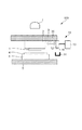
図8に、インプリント材の消費前後におけるインプリント材吐出装置の状態を示す。図8(a)はインプリント材の消費前、図8(b)はインプリント材の消費後の状態を示している。上述したように、収容部材12の内部は、分離膜14によって、インプリント材の収容部15と充填液部16とに区切られている。インプリント材の消費とともに分離膜14が変形し、収容部15は容積を減らしていく。分離膜14が移動してもポンプ22とフィルタ23による循環ろ過が可能なように、第1の開口20と第2の開口21とは、収容部15の中でも充填液部16から遠い側(図8でいうと右側の側面よりも左側の側面に近い側)に配置することが好ましい。
FIG. 8 shows the state of the imprint material discharging device before and after the consumption of the imprint material. FIG. 8A shows a state before consumption of the imprint material, and FIG. 8B shows a state after consumption of the imprint material. As described above, the inside of the containing
収容部15の内部には、空気が存在している場合がある。例えば、図5に示すようにあえて空気を取り込んでいる場合がある。また、図4に示すように空気を収容部15の内部に積極的には取り込んでいないが、収容部15にインプリント材を封入する際に空気が混入したり、インプリント材に溶存していた気体が気泡となって存在したりする場合もある。インプリント材中に存在する空気がポンプ22やフィルタ23に送られると、目詰まり等の原因となる場合がある。従って、第1の開口20は空気をなるべく吸引しないよう、第1の開口20からインプリント材を供給している際に、収容部の重力方向下方に開口するように配置することが好ましい。即ち、第1の開口20は第2の開口21よりも重力方向下方に開口していることが好ましい。他にも、第1の開口20は、収容部15の側面のうち、上面よりも底面に近い位置に開口していることが好ましい。
Air may be present inside the
また、インプリント材中の空気(気泡)は、浮力によって収容部15の内部で重力方向上方である上面側に移動する。そこで、図9に示すように、収容部15の重力方向上方の面である上面に、空気を捕獲するための凹部であるトラップ空間26を設けることが好ましい。空気はこのトラップ空間26に集まるので、収容部15内に循環ろ過による緩やかな流れがあっても、空気とインプリント材とを良好に分離することができる。
Further, the air (air bubbles) in the imprint material moves to the upper surface side in the
トラップ空間26のように、収容部15内には、気液界面が存在する場合がある。第2の開口21の近くに気液界面があると、インプリント材が泡立ったり、インプリント材中に空気が混入したりすることがある。そこで、第2の開口21は、収容部15の上面から重力方向下方の位置で、気液界面よりも重力方向下方の位置に開口し、インプリント材を収容部15に供給する構成とすることが好ましい。この為、第2の開口21を収容部15の上面から突出した凸形状としてもよいし、第2の開口21にチューブを接続し、チューブの先を気液界面より下まで導くようにしてもよい。
Like the
通路は、吐出部材11を通る構成であってもよい。このような構成を図12に示す。この場合、通路は、第1の開口20から、吐出部材11の内部を通り、第2の開口21へと続いている。しかし、インプリント材の通り道である通路内には、領域33は含まれていない。即ち、第1の開口20から通路の内部に供給されたインプリント材は、領域33を介さずに、第2の開口21から収容部に供給される。
The passage may be configured to pass through the
図12に示す形態では、領域33の近くに第1の開口20が開口するので、インプリント材のフィルタによるろ過と吐出のバランスを考慮して設計を行うことが求められる。
In the form shown in FIG. 12, the
これに対し、第1の開口20から通路の内部に供給されたインプリント材を、領域33を介して、第2の開口21から収容部に供給する例を、図14に示す。このような構成では、インプリント材のフィルタによるろ過と吐出のバランスをとることが困難となる。
On the other hand, FIG. 14 shows an example in which the imprint material supplied from the
次に、インプリント材吐出装置の収容部15に、初期にインプリント材を充填する方法を説明する。図10に示すように、インプリント材の充填口27は収容部15の側面に設けられていて、インプリント材を充填する際にはこの側面を、即ち充填口27を、重力方向上方に向ける。そして2つの充填口27のうち片側からインプリント材を供給し、片側から空気を供給する。インプリント材を充填するときに、ポンプ22やフィルタ23等の内部通路にもインプリント材を充填し、収容部15内に空気を残留しにくくする。そこで、インプリント材を収容部15に充填するときには、ポンプ22を駆動させることが好ましい。初期にポンプ22やフィルタ23等の内部通路に存在していた空気は、ポンプ22を駆動させることでインプリント材と置換され、第2の開口21から出てくる。空気は、直近にある充填口27から供給される為、必要以上にインプリント材を泡立たせることなく、収容部15およびフィルタ23を含む通路にインプリント材を充填することができる。
Next, a method of initially filling the
尚、収容部15へのインプリント材の充填は、初期のみでなく、インプリント装置の使用時にも行うことができる。例えば、充填口27から収容部15にインプリント材を充填しつつ、インプリント装置を使用してもよい。
It should be noted that the filling of the imprint material into the
フィルタ23の内部には、フィルタの構造上空気が残りやすい。そこで、フィルタ23に対して重力方向下方から上方向きにインプリント材を充填することで、空気残りを少なくすることができる。例えば、図10に示すように、インプリント材の充填時において、フィルタ23の上流側を重力方向下方、下流側を重力方向上方にすることが好ましい。また、このような配置としておき、充填口27のうち1つを重力方向上方にして、収容部15から空気を供給しやすくすることが好ましい。さらに、第1の開口20を重力方向下方に配置して、フィルタ23にインプリント材が充填されやすくすることが好ましい。
Air tends to remain inside the
フィルタ23については、平均口径が大きすぎるフィルタであると、インプリント材中の異物を十分に除去することが難しくなる。従って、平均口径が10nm以下のフィルタを用いることが好ましく、平均口径が5nm以下のフィルタを用いることがより好ましい。一方、平均口径が小さすぎるフィルタを用いると、フィルタでの圧力損失によって通路でのインプリント材の循環が難しくなる。この為、平均口径が2nm以上のフィルタを用いることが好ましい。
If the average diameter of the
インプリント材中に存在する異物の量が多いと、フィルタは短時間で目詰まりを起こす場合がある。そこで、プレフィルタとして大きな異物を除去するフィルタを循環の際の上流側に配置し、下流側に小さな異物を除去するフィルタを配置するような多段フィルタ構成にすることも好ましい。大きな異物を除去するフィルタとは、例えば平均口径が50nm以上200nm以下のフィルタである。小さな異物を除去するフィルタとは、例えば平均口径が2nm以上10nm以下のフィルタである。 If the amount of foreign matter present in the imprint material is large, the filter may be clogged in a short time. Therefore, it is also preferable to adopt a multi-stage filter configuration in which a filter for removing large foreign matters is arranged as a prefilter on the upstream side in circulation and a filter for removing small foreign matters is arranged on the downstream side. The filter for removing large foreign matters is, for example, a filter having an average aperture of 50 nm or more and 200 nm or less. The filter for removing small foreign matters is, for example, a filter having an average aperture of 2 nm or more and 10 nm or less.
フィルタ23は、メンブレンタイプまたは中空糸膜タイプのものを用いることが好ましい。これらのフィルタは、異物をろ過する膜に微細な穴を多数設けていて、口径以上の異物を通過させないことで異物を除去する方式である。他にも、フィルタ23の形成材料としては、ポリエチレン、フッ素系樹脂、ナイロン等が挙げられる。また、インプリント材中に存在する金属量が極めて少ないことが求められる。そこで、金属を吸着したりイオン交換したりする機能のあるフィルタを用いることが好ましい。これらのフィルタを複数、直列または並列に配置することも好ましい。
The
ポンプ22としては、例えばダイアフラムポンプ、シリンジポンプ、チューブポンプ、ギアポンプ等を用いることができる。ポンプ22の送液流量は、100mL/min以下とすることが好ましい。流量を大きくするとフィルタを通過させるための流路抵抗(圧力損失)が大きくなるため、高出力のポンプが必要となる。この為、送液流量が20mL/min以下のポンプを用いることで、ポンプを小型にすることができる。
As the
ポンプの駆動に伴うインプリント材の圧力変動(脈動)が大きいと、吐出部材からインプリント材が漏れやすくなる。その為、吐出口のメニスカスを破壊しない程度の圧力変動に抑えることが好ましい。例えば、圧力変動が±300Pa以内となるようにポンプを駆動させることが好ましい。 When the pressure fluctuation (pulsation) of the imprint material due to the driving of the pump is large, the imprint material easily leaks from the discharge member. Therefore, it is preferable to suppress the pressure fluctuation to the extent that the meniscus of the discharge port is not destroyed. For example, it is preferable to drive the pump so that the pressure fluctuation is within ±300 Pa.
インプリント材吐出装置は、ポンプ22を動作させるために、コントローラーを備えている。一定の流量を維持して送液するように制御する為、フィルタ23が目詰まりして流路抵抗が大きくなると、駆動電圧が大きくなる。従って、コントローラーにおけるポンプの駆動電圧を常時監視し、駆動電圧が一定の値を超えた場合には、インプリント装置に対してフィルタ交換を促す警告を発することができる。フィルタ23をカートリッジ形態のインプリント材吐出装置として一体化すると、ユーザーはインプリント材吐出装置を交換することで、すぐにインプリント装置を利用することができる。ポンプ22やフィルタ23の異常検知には、それらの状態を監視するセンサーを設けていてもよいし、圧力センサーや流量センサー等を配管中に構成しておいてもよい。
The imprint material discharging device includes a controller for operating the
インプリント材吐出装置には、基板上に吐出するインプリント材の量及び着弾位置が非常に高精度であることが求められる。その為に、吐出部材の吐出口におけるメニスカス形状を安定に保つ必要がある。インプリント材吐出装置は、ポンプ22の駆動によってインプリント材の圧力が変動する場合がある。そこで、インプリント材吐出装置からインプリント材を吐出している間はポンプ22の駆動を停止させることが好ましい。
The imprint material ejecting apparatus is required to have extremely high accuracy in the amount and the landing position of the imprint material ejected onto the substrate. Therefore, it is necessary to keep the meniscus shape at the discharge port of the discharge member stable. In the imprint material discharging device, the pressure of the imprint material may change due to the driving of the
インプリント工程は、基板へのインプリント材の吐出、インプリント材へのモールドの接触、露光、モールドの剥離、を繰り返しながら基板上の各領域にパターンを形成していく。従って、基板へインプリント材を吐出している時間以外のタイミングで、収容部15の循環ろ過を行うことが好ましい。循環ろ過のタイミングは、基板交換やロット交換のタイミングであってもよい。
In the imprint process, a pattern is formed in each region on the substrate by repeating ejection of the imprint material onto the substrate, contact of the mold with the imprint material, exposure, and release of the mold. Therefore, it is preferable to circulate and filter the containing
また、循環ろ過は、収容部15内にパーティクルやゲル等の異物が増加してきたときに実施すればよい。そこで、循環ろ過は装置が稼働していない時に実施してもよい。インプリント工程を実施しているときはポンプ22を停止しておき、装置のメンテナンス時やインプリント処理する基板がない時間帯に循環ろ過を行ってもよい。また、インプリント装置や吐出装置にタイマー機能を構成し、一定時間が経過したら循環ろ過を行ってもよい。さらに、インプリント装置や吐出装置からのプログラミングされた指令でポンプ22の制御を行ってもよいし、ユーザーがポンプ22を駆動させる方法でもよい。
In addition, the circulation filtration may be carried out when foreign matters such as particles and gel increase in the containing
図11に、収容部の移動機構30を構成したインプリント装置を示す。収容部材12は、移動機構30によってインプリント材を吐出する位置とメンテナンスを行う位置とを移動することができる。メンテナンスを行う位置には、吐出部材11から出たインプリント材を受ける受け皿31を配置することが好ましい。
FIG. 11 shows an imprint apparatus that constitutes the moving
移動機構30によってメンテナンスを行う位置へ移動して循環ろ過を実施すれば、圧力変動が大きく吐出部材11からインプリント材が漏れ出た場合でも、受け皿31でインプリント材を受けることができる。ポンプ22の出力を大きくして循環ろ過流量を上げ、早急に循環ろ過を終えてインプリント工程に戻したい場合等に有効である。
If the moving
循環ろ過を実施するタイミングは、インプリント装置でインプリント材吐出装置を使用開始してからの経過時間、インプリント材の使用量、前回の循環ろ過からの経過時間、インプリント材吐出装置の保管環境履歴等に応じて決定するとよい。また、環境やインプリント材の種類によってゲル化の度合いが違う為、インプリント材の種類によって決定してもよい。 The timing of circulating filtration is the time elapsed since the imprinting device was started to be used by the imprinting device, the amount of imprinting material used, the time elapsed since the last circulating filtration, and the storage of the imprinting device discharging device. It may be decided according to the environmental history and the like. Further, since the degree of gelation varies depending on the environment and the type of imprint material, it may be determined depending on the type of imprint material.
また、インプリント材残量が減れば循環ろ過する量を減らしてよく、収容部内のインプリント材の残量に応じて、循環ろ過のタイミングや流量等の条件を変えてもよい。 Further, if the remaining amount of the imprint material decreases, the amount of circulating filtration may be reduced, and the conditions such as the timing and the flow rate of the circulating filtration may be changed according to the remaining amount of the imprint material in the accommodating portion.
ポンプ22は間欠動作させなくてもよい。ポンプ22を制御して低流量で常時駆動させれば、圧力変動を抑制することができる。ポンプ22としてダイアフラムポンプを用いた場合には、ダイアフラムの振動幅を小さくすることで圧力変動を抑え、常時循環ろ過を行ってもよい。
The
1 モールド
8 インプリント材
10 インプリント材吐出装置
11 吐出部材
12 収容部材
15 収容部
20 第1の開口
21 第2の開口
23 フィルタ
28 通路形成部材
DESCRIPTION OF
Claims (24)
前記インプリント材を収容する収容部を有する収容部材と、
前記収容部に接続する通路と、
前記インプリント材を吐出する吐出部材と、
を有し、
前記吐出部材は、前記インプリント材が流通する領域と、前記領域と連通し前記領域を流通する前記インプリント材が外部に吐出される開口である吐出口と、駆動によって前記領域を流通する前記インプリント材を前記吐出口から吐出させる圧電素子または発熱抵抗体と、を有し、
前記領域は、前記吐出口と、前記圧電素子または発熱抵抗体との間の領域であって、前記吐出部材の内部の領域であり、
前記通路は、前記収容部に収容されたインプリント材を前記通路の内部に供給するための、前記収容部に開口する第1の開口と、前記第1の開口から供給されたインプリント材を前記収容部に供給するための、前記収容部に開口する第2の開口とを有し、
前記通路の前記第1の開口と前記第2の開口との間には前記インプリント材をろ過するフィルタがあり、前記第1の開口から前記通路の内部に供給されたインプリント材は、前記領域を介さずに、前記第2の開口から前記収容部に供給され、
前記収容部材と前記通路と前記吐出部材とが一体となったカートリッジ形態の吐出装置であることを特徴とするインプリント材吐出装置。 An imprint material ejecting device for ejecting an imprint material for forming a pattern by contacting a mold onto a substrate,
A storage member having a storage portion for storing the imprint material,
A passage connected to the accommodation portion,
A discharge member for discharging the imprint material ,
Have
The discharge member has a region where the imprint material flows, a discharge port that is an opening that communicates with the region and discharges the imprint material flowing through the region to the outside, and the discharge member that flows through the region by driving A piezoelectric element or a heating resistor for discharging the imprint material from the discharge port,
The region is a region between the discharge port and the piezoelectric element or the heating resistor, and is a region inside the discharge member,
The passage includes a first opening for opening the storage portion to supply the imprint material stored in the storage portion to the inside of the passage, and an imprint material supplied from the first opening. A second opening for opening into the accommodation portion for supplying to the accommodation portion,
A filter for filtering the imprint material is provided between the first opening and the second opening of the passage, and the imprint material supplied from the first opening into the passage is Supplied to the accommodation portion from the second opening without passing through the region ,
An imprint material ejecting apparatus, which is an ejecting apparatus in a cartridge form in which the accommodating member, the passage, and the ejecting member are integrated .
前記インプリント材を収容する収容部を有する収容部材と、
前記収容部に接続する通路と、
前記インプリント材を吐出する吐出部材と、
を有し、
前記吐出部材は、前記インプリント材が流通する領域と、前記領域と連通し前記領域を流通する前記インプリント材が外部に吐出される開口である吐出口と、駆動によって前記領域を流通する前記インプリント材を前記吐出口から吐出させる圧電素子または発熱抵抗体と、を有し、
前記領域は、前記吐出口と、前記圧電素子または発熱抵抗体との間の領域であって、前記吐出部材の内部の領域であり、
前記通路は、前記収容部に収容されたインプリント材を前記通路の内部に供給するための、前記収容部に開口する第1の開口と、前記第1の開口から供給されたインプリント材を前記収容部に供給するための、前記収容部に開口する第2の開口とを有し、
前記通路の前記第1の開口と前記第2の開口との間には前記インプリント材をろ過するフィルタがあり、
前記通路は前記領域と異なる部分に設けられており、
前記収容部材と前記通路と前記吐出部材とが一体となったカートリッジ形態の吐出装置であることを特徴とするインプリント材吐出装置。 An imprint material ejecting device for ejecting an imprint material for forming a pattern by contacting a mold onto a substrate,
A storage member having a storage portion for storing the imprint material,
A passage connected to the accommodation portion,
A discharge member for discharging the imprint material ,
Have
The discharge member has a region where the imprint material flows, a discharge port that is an opening that communicates with the region and discharges the imprint material flowing through the region to the outside, and the discharge member that flows through the region by driving A piezoelectric element or a heating resistor for discharging the imprint material from the discharge port,
The region is a region between the discharge port and the piezoelectric element or the heating resistor, and is a region inside the discharge member,
The passage includes a first opening for opening the storage portion to supply the imprint material stored in the storage portion to the inside of the passage, and an imprint material supplied from the first opening. A second opening for opening into the accommodation portion for supplying to the accommodation portion,
There is a filter for filtering the imprint material between the first opening and the second opening of the passage,
The passage is provided in a portion different from the area ,
An imprint material ejecting apparatus, which is an ejecting apparatus in a cartridge form in which the accommodating member, the passage, and the ejecting member are integrated .
Priority Applications (7)
| Application Number | Priority Date | Filing Date | Title |
|---|---|---|---|
| SG10201602050WA SG10201602050WA (en) | 2015-04-03 | 2016-03-16 | Imprint material discharging device |
| TW105108098A TWI614110B (en) | 2015-04-03 | 2016-03-16 | Imprint material discharging device and imprint apparatus |
| US15/083,028 US20160288378A1 (en) | 2015-04-03 | 2016-03-28 | Imprint material discharging device |
| MYPI2016000579A MY177437A (en) | 2015-04-03 | 2016-03-31 | Imprint material discharge device |
| EP16000752.2A EP3076238B1 (en) | 2015-04-03 | 2016-03-31 | Imprint material discharging device |
| CN201610197474.9A CN106042650B (en) | 2015-04-03 | 2016-03-31 | Impression materials discharger and Embosser |
| KR1020160040231A KR101986877B1 (en) | 2015-04-03 | 2016-04-01 | Imprint material discharging device |
Applications Claiming Priority (2)
| Application Number | Priority Date | Filing Date | Title |
|---|---|---|---|
| JP2015076992 | 2015-04-03 | ||
| JP2015076992 | 2015-04-03 |
Related Child Applications (1)
| Application Number | Title | Priority Date | Filing Date |
|---|---|---|---|
| JP2020071663A Division JP6882574B2 (en) | 2015-04-03 | 2020-04-13 | Imprint material discharge device |
Publications (3)
| Publication Number | Publication Date |
|---|---|
| JP2016197710A JP2016197710A (en) | 2016-11-24 |
| JP2016197710A5 JP2016197710A5 (en) | 2019-02-14 |
| JP6700794B2 true JP6700794B2 (en) | 2020-05-27 |
Family
ID=57358607
Family Applications (2)
| Application Number | Title | Priority Date | Filing Date |
|---|---|---|---|
| JP2016002753A Active JP6700794B2 (en) | 2015-04-03 | 2016-01-08 | Imprint material discharge device |
| JP2020071663A Active JP6882574B2 (en) | 2015-04-03 | 2020-04-13 | Imprint material discharge device |
Family Applications After (1)
| Application Number | Title | Priority Date | Filing Date |
|---|---|---|---|
| JP2020071663A Active JP6882574B2 (en) | 2015-04-03 | 2020-04-13 | Imprint material discharge device |
Country Status (4)
| Country | Link |
|---|---|
| JP (2) | JP6700794B2 (en) |
| CN (1) | CN106042650B (en) |
| SG (1) | SG10201602050WA (en) |
| TW (1) | TWI614110B (en) |
Families Citing this family (7)
| Publication number | Priority date | Publication date | Assignee | Title |
|---|---|---|---|---|
| US10421283B2 (en) | 2017-09-06 | 2019-09-24 | Canon Kabushiki Kaisha | Ejection material receiving unit, ejection material ejecting apparatus, and manufacturing method of flexible member |
| TWI680063B (en) * | 2017-09-06 | 2019-12-21 | 日商佳能股份有限公司 | Ejection material receiving unit, ejection material ejecting apparatus, and manufacturing method of flexible member |
| JP6983587B2 (en) * | 2017-09-06 | 2021-12-17 | キヤノン株式会社 | Discharge material storage unit and discharge material discharge device |
| JP2019125619A (en) * | 2018-01-12 | 2019-07-25 | キヤノン株式会社 | Discharge device and imprint device |
| JP7277127B2 (en) * | 2018-04-11 | 2023-05-18 | キヤノン株式会社 | Ejection Material Filling Method, Ejection Material Ejection Apparatus, and Imprint Apparatus |
| US10894420B2 (en) | 2018-04-11 | 2021-01-19 | Canon Kabushiki Kaisha | Ejection-material injecting method, ejection-material ejection apparatus, and imprinting apparatus |
| CN110394979B (en) * | 2018-04-25 | 2021-09-21 | 中国航发商用航空发动机有限责任公司 | Photocuring forming equipment |
Family Cites Families (27)
| Publication number | Priority date | Publication date | Assignee | Title |
|---|---|---|---|---|
| JP3706294B2 (en) * | 2000-03-27 | 2005-10-12 | 東京エレクトロン株式会社 | Treatment liquid supply apparatus and treatment liquid supply method |
| JP2002273113A (en) * | 2001-03-15 | 2002-09-24 | Koganei Corp | Filter, chemical liquid supply device and chemical liquid supply method |
| JP2003251821A (en) * | 2001-10-05 | 2003-09-09 | Canon Inc | Liquid storage container, liquid supply system, liquid using unit, ink tank, ink supply system, inkjet recording head and recording apparatus |
| KR20060071430A (en) * | 2003-10-22 | 2006-06-26 | 가부시키가이샤 니콘 | Exposure apparatus, exposure method, and method for manufacturing device |
| JP4716677B2 (en) * | 2004-06-01 | 2011-07-06 | キヤノンファインテック株式会社 | Ink supply apparatus, recording apparatus, ink supply method, and recording method |
| TWI362059B (en) * | 2004-11-25 | 2012-04-11 | Az Electronic Mat Ip Japan Kk | Photoresist coating solution supply system and method for supplying photoresist coating solution using thereof, and photoresist coating system using thereof |
| US8015939B2 (en) * | 2006-06-30 | 2011-09-13 | Asml Netherlands B.V. | Imprintable medium dispenser |
| JP4755119B2 (en) * | 2007-02-14 | 2011-08-24 | 株式会社リコー | Liquid supply member for liquid discharge head, liquid discharge apparatus, and image forming apparatus |
| US8864296B2 (en) * | 2008-01-30 | 2014-10-21 | Hewlett-Packard Development Company, L.P. | System for priming a fluid dispenser by expanding gas bubbles |
| JP5209431B2 (en) * | 2008-09-30 | 2013-06-12 | 富士フイルム株式会社 | Inkjet recording device |
| US20100102471A1 (en) * | 2008-10-24 | 2010-04-29 | Molecular Imprints, Inc. | Fluid transport and dispensing |
| US20100101493A1 (en) * | 2008-10-27 | 2010-04-29 | Molecular Imprints, Inc. | Dispense System |
| JP2010120340A (en) * | 2008-11-21 | 2010-06-03 | Canon Inc | Fluid discharging device and recording device |
| JP5277506B2 (en) * | 2009-02-09 | 2013-08-28 | キヤノンファインテック株式会社 | Inkjet recording head, ink storage device |
| US20110140304A1 (en) * | 2009-12-10 | 2011-06-16 | Molecular Imprints, Inc. | Imprint lithography template |
| JP5451450B2 (en) * | 2010-02-24 | 2014-03-26 | キヤノン株式会社 | Imprint apparatus, template thereof, and article manufacturing method |
| JP5335717B2 (en) * | 2010-03-16 | 2013-11-06 | 富士フイルム株式会社 | Resist composition arranging apparatus and pattern forming body manufacturing method |
| JP2013022491A (en) * | 2011-07-19 | 2013-02-04 | Seiko Epson Corp | Drawing device |
| JP5686779B2 (en) * | 2011-10-14 | 2015-03-18 | キヤノン株式会社 | Imprint apparatus and article manufacturing method using the same |
| JP6159072B2 (en) * | 2011-11-30 | 2017-07-05 | キヤノン株式会社 | Imprint apparatus, imprint method, and article manufacturing method |
| JP5824379B2 (en) * | 2012-02-07 | 2015-11-25 | キヤノン株式会社 | Imprint apparatus, imprint method, and article manufacturing method |
| JP5930832B2 (en) * | 2012-04-27 | 2016-06-08 | キヤノン株式会社 | Method for producing photocured product |
| JP5995567B2 (en) * | 2012-07-12 | 2016-09-21 | キヤノン株式会社 | Imprint apparatus and article manufacturing method using the same |
| US9887095B2 (en) * | 2013-03-12 | 2018-02-06 | Taiwan Semiconductor Manufacturing Company, Ltd. | System and method for an etch process with silicon concentration control |
| JP2014216471A (en) * | 2013-04-25 | 2014-11-17 | 大日本印刷株式会社 | Imprint device and imprint method |
| JP6362109B2 (en) * | 2013-10-04 | 2018-07-25 | キヤノン株式会社 | Imprint apparatus and component manufacturing method |
| JP6264888B2 (en) * | 2014-01-07 | 2018-01-24 | セイコーエプソン株式会社 | Liquid ejector |
-
2016
- 2016-01-08 JP JP2016002753A patent/JP6700794B2/en active Active
- 2016-03-16 SG SG10201602050WA patent/SG10201602050WA/en unknown
- 2016-03-16 TW TW105108098A patent/TWI614110B/en active
- 2016-03-31 CN CN201610197474.9A patent/CN106042650B/en active Active
-
2020
- 2020-04-13 JP JP2020071663A patent/JP6882574B2/en active Active
Also Published As
| Publication number | Publication date |
|---|---|
| TW201636225A (en) | 2016-10-16 |
| JP6882574B2 (en) | 2021-06-02 |
| JP2016197710A (en) | 2016-11-24 |
| CN106042650B (en) | 2018-01-02 |
| SG10201602050WA (en) | 2016-11-29 |
| JP2020129671A (en) | 2020-08-27 |
| TWI614110B (en) | 2018-02-11 |
| CN106042650A (en) | 2016-10-26 |
Similar Documents
| Publication | Publication Date | Title |
|---|---|---|
| JP6700794B2 (en) | Imprint material discharge device | |
| KR101986877B1 (en) | Imprint material discharging device | |
| JP2018058255A (en) | Liquid injection device and fluid discharge method for the same | |
| WO2015190201A1 (en) | Inkjet printing apparatus | |
| KR20160118941A (en) | Liquid discharge apparatus, imprint apparatus and part manufacturing method | |
| US10562315B2 (en) | Liquid ejecting apparatus and filling method of liquid ejecting apparatus | |
| TWI613095B (en) | Liquid discharging apparatus, imprint apparatus, and method of manufacturing a component | |
| JP2016197710A5 (en) | ||
| CN111559173B (en) | Liquid ejecting apparatus | |
| US11143956B2 (en) | Ejection device and imprint apparatus | |
| US10406731B2 (en) | Application device, imprinting apparatus, and method for manufacturing object | |
| JP7277127B2 (en) | Ejection Material Filling Method, Ejection Material Ejection Apparatus, and Imprint Apparatus | |
| US11520227B2 (en) | Ejection material filling device, pressure regulation device, and ejection material filling method | |
| JP2007276393A (en) | Inkjet recording apparatus | |
| JP2023123123A (en) | Liquid discharge device and imprint device | |
| CN112793304A (en) | Liquid ejecting apparatus and maintenance method of liquid ejecting apparatus | |
| JP2009208368A (en) | Flow path forming member, liquid injection head, and liquid injection apparatus | |
| JP2018006470A (en) | Imprint material discharge device | |
| JP7388023B2 (en) | Liquid supply device, liquid injection device, and control method for liquid supply device | |
| JP2018006469A (en) | Imprint material discharge device | |
| JP2022001417A (en) | Liquid jet system and liquid storage mechanism |
Legal Events
| Date | Code | Title | Description |
|---|---|---|---|
| A521 | Written amendment |
Free format text: JAPANESE INTERMEDIATE CODE: A523 Effective date: 20181220 |
|
| A621 | Written request for application examination |
Free format text: JAPANESE INTERMEDIATE CODE: A621 Effective date: 20181220 |
|
| A977 | Report on retrieval |
Free format text: JAPANESE INTERMEDIATE CODE: A971007 Effective date: 20190919 |
|
| A131 | Notification of reasons for refusal |
Free format text: JAPANESE INTERMEDIATE CODE: A131 Effective date: 20191001 |
|
| A521 | Written amendment |
Free format text: JAPANESE INTERMEDIATE CODE: A523 Effective date: 20191129 |
|
| TRDD | Decision of grant or rejection written | ||
| A01 | Written decision to grant a patent or to grant a registration (utility model) |
Free format text: JAPANESE INTERMEDIATE CODE: A01 Effective date: 20200331 |
|
| A61 | First payment of annual fees (during grant procedure) |
Free format text: JAPANESE INTERMEDIATE CODE: A61 Effective date: 20200501 |
|
| R151 | Written notification of patent or utility model registration |
Ref document number: 6700794 Country of ref document: JP Free format text: JAPANESE INTERMEDIATE CODE: R151 |