JP6700680B2 - Support apparatus, lithographic apparatus, and article manufacturing method - Google Patents
Support apparatus, lithographic apparatus, and article manufacturing method Download PDFInfo
- Publication number
- JP6700680B2 JP6700680B2 JP2015121425A JP2015121425A JP6700680B2 JP 6700680 B2 JP6700680 B2 JP 6700680B2 JP 2015121425 A JP2015121425 A JP 2015121425A JP 2015121425 A JP2015121425 A JP 2015121425A JP 6700680 B2 JP6700680 B2 JP 6700680B2
- Authority
- JP
- Japan
- Prior art keywords
- control
- unit
- information
- units
- control mode
- Prior art date
- Legal status (The legal status is an assumption and is not a legal conclusion. Google has not performed a legal analysis and makes no representation as to the accuracy of the status listed.)
- Active
Links
Images

Landscapes
- Exposure And Positioning Against Photoresist Photosensitive Materials (AREA)
- Container, Conveyance, Adherence, Positioning, Of Wafer (AREA)
- Feedback Control In General (AREA)
Description
本発明は、支持装置、リソグラフィ装置、および物品の製造方法に関する。 The present invention relates to a support device, a lithographic apparatus and a method for manufacturing an article.
従来の支持装置においては、例えば、その設置面からの振動を絶縁する除振機能と、装置が発する振動を減衰させる制振機能と、その上に搭載されている構造体の姿勢を保つためのレベリング機能とを有している。また、支持装置は、それぞれが空気ばねやリニアモータ等のアクチュエータを含む複数の能動的支持脚(駆動部)を備えている(例えば特許文献1)。 In a conventional support device, for example, a vibration isolation function that insulates the vibration from the installation surface, a vibration damping function that attenuates the vibration generated by the device, and a structure for maintaining the posture of the structure mounted thereon are provided. It has a leveling function. Further, the supporting device includes a plurality of active supporting legs (driving parts) each including an actuator such as an air spring or a linear motor (for example, Patent Document 1).
支持装置におけるレベリング機能は、概ね次のようなものである。すなわち、制御対象である構造体と設置面との間の相対位置が各々の能動的支持脚において計測される。各能動的支持脚での計測結果から、構造体の位置、姿勢および形状(Z、θx、θy、ねじれ等)が演算され、それらが目標値となるように制御される。 The leveling function of the supporting device is generally as follows. That is, the relative position between the structure to be controlled and the installation surface is measured at each active support leg. The position, posture, and shape (Z, θx, θy, twist, etc.) of the structure are calculated from the measurement results of each active support leg, and these are controlled to be the target values.
近年、例えば露光装置では形成すべきパターンの高精細化やパターニングの高精度化がますます求められ、構造体の僅かな変形でも、装置の性能に影響を与えてしまい、所定の性能を達成することが困難となっている。つまり、構造体の変形の低減に対する要求がますます厳しくなってきている。 In recent years, for example, in an exposure apparatus, higher definition of a pattern to be formed and higher accuracy of patterning are increasingly demanded, and even a slight deformation of a structure affects the performance of the apparatus to achieve a predetermined performance. Has become difficult. That is, the demand for reducing the deformation of the structure is becoming more and more strict.
一方で、とりわけフラットパネルディスプレイ(FPD)用の露光装置の大型化が顕著である。そのため、装置設置後に数カ月から数年間にわたって、設置面(床面等)が徐々に沈降していく現象(経時的な設置面の変形)が生じうる。 On the other hand, the size of an exposure apparatus for a flat panel display (FPD) is particularly large. Therefore, a phenomenon (deformation of the installation surface over time) in which the installation surface (floor surface or the like) gradually sinks may occur over several months to several years after the installation of the device.
複数の能動的支持脚(駆動部)の間において、経時的な設置面の変形量に差が生じるような場合、支持装置は構造体をその設置面に倣うように制御する。そのため、構造体が変形してしまい、支持装置によって支持された構造体を含む装置の性能が低下しうる。 When there is a difference in the amount of deformation of the installation surface over time among the plurality of active support legs (driving parts), the support device controls the structure to follow the installation surface. Therefore, the structure may be deformed, and the performance of the device including the structure supported by the supporting device may deteriorate.
本発明は、経時的な設置面の変形に対する構造体の変形を軽減するのに有利な支持装置を提供することを例示的目的とする。 It is an exemplary object of the present invention to provide a supporting device that is advantageous in reducing the deformation of the structure due to the deformation of the installation surface over time.
本発明の一側面によれば、設置面上に対象物を支持するための複数の駆動部と、前記複数の駆動部のうちの少なくとも一部に関してそれぞれ設けられ、それぞれが前記設置面に対する前記対象物の位置を計測する複数の計測部と、前記複数の計測部の出力に基づいて前記複数の駆動部を制御する制御部とを含み、前記制御部は、前記対象物の位置および姿勢のうちの少なくとも一方を制御し且つ前記対象物の形状を制御しない第1制御モードと、前記少なくとも一方と前記形状とを制御する第2制御モードとを有し、前記制御部は、前記第1制御モードにおいて前記複数の計測部によりそれぞれ得られた複数の位置に基づいて前記第2制御モードにおける目標値を更新することを特徴とする支持装置が提供される。 According to one aspect of the present invention, a plurality of drive units for supporting an object on an installation surface, and at least a part of the plurality of drive units are respectively provided, and each of the objects is provided on the installation surface. A plurality of measurement units that measure the position of an object, and a control unit that controls the plurality of drive units based on the outputs of the plurality of measurement units, wherein the control unit is one of the positions and orientations of the object. And a second control mode in which the shape of the object is not controlled, and a second control mode in which the shape and the shape of the object are controlled. The control unit includes the first control mode. In the supporting device, the target value in the second control mode is updated based on the plurality of positions obtained by the plurality of measuring units.
本発明によれば、例えば、経時的な設置面の変形に対する構造体の変形を軽減するのに有利な支持装置を提供することができる。 According to the present invention, it is possible to provide a supporting device that is advantageous for reducing the deformation of the structure due to the deformation of the installation surface over time, for example.
以下、図面を参照して本発明の好適な実施形態について詳細に説明する。なお、本発明は以下の実施形態に限定されるものではなく、本発明の実施に有利な具体例を示すにすぎない。また、以下の実施形態の中で説明されている特徴の組み合わせの全てが本発明の課題解決のために必須のものであるとは限らない。 Hereinafter, preferred embodiments of the present invention will be described in detail with reference to the drawings. It should be noted that the present invention is not limited to the following embodiments, but merely shows specific examples advantageous for carrying out the present invention. Further, not all of the combinations of features described in the following embodiments are essential for solving the problems of the present invention.
<第1実施形態>
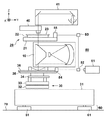
図1に、本発明の支持装置が適用されうる露光装置の概略構成を示す。なお、本発明は、後述するように多くの産業機械に適用可能であるが、ここでは、パターン形成を基板に行うリソグラフィ装置のうちの露光装置に関して説明する。本実施形態に係る露光装置は例えば、FPD用のガラス基板のような大型の基板にマスクのパタ−ンを転写する走査型投影露光装置である。図1において、投影光学系10を挟んで垂直方向(Z軸方向)の上側にマスクステージ20が配置され、下側には基板ステージ30が配置されている。これらマスクステージ20と基板ステージ30はそれぞれ個別に移動可能であり、これらの移動位置はともにレーザ干渉計システム50により計測・制御が可能である。
<First Embodiment>
FIG. 1 shows a schematic configuration of an exposure apparatus to which the supporting apparatus of the present invention can be applied. Note that the present invention can be applied to many industrial machines as described later, but here, an exposure apparatus of a lithography apparatus that performs pattern formation on a substrate will be described. The exposure apparatus according to the present embodiment is, for example, a scanning projection exposure apparatus that transfers a pattern of a mask onto a large substrate such as a glass substrate for FPD. In FIG. 1, the
基板ステージ30は、構造体31上に配置したYステージ32およびXステージ33を有する。この構造体31が、複数の能動的支持脚61を有する支持装置としての能動的除振装置60によって支持される。なお、X方向およびY方向は互いに直交する方向とする。このXYステージ上にθZステージ34が搭載され、その上に基板テーブル35が配置され、これにより露光されるべき基板36が支持される。従って、基板36は、基板ステージ30によりX,Y,Z方向に移動可能であると共に、XY面内でも回転可能に支持される。θZステージ34は、露光時、基板36の表面を投影光学系10の基板側焦点面に一致させるためのものである。
The
マスクステージ20は、マスクステージ基板21と、その上に配置されたXYθステージ22とを含み、この上に、投影されるべきパタ−ンを有するマスク23が配置される。従って、マスク23はXおよびY方向に移動可能であると共にXY面内で回転可能に支持される。マスクステージ20の上方には、マスク23と基板36の像を投影光学系10を介して観察できる観察光学系40が配置され、さらにその上方に照明光学系41が配置されている。マスクステージ20および基板ステージ30の位置は、レーザ干渉計システム50により計測・制御される。
The
レーザ干渉計システム50は、レ−ザヘッド51、レーザ干渉計52,53と、基板テーブル35に取り付けられたミラ−54と、マスクステージ基板21に取り付けられたミラ−55とを有する。ここで、レーザ干渉計システム50のレーザビーム位置は、マスクステージ20については、上下方向(投影光学系10の光軸方向)では、ほぼ投影光学系10のマスク側焦点面に設定されている。また、レーザ干渉計システム50のレーザビーム位置は、基板ステージ30についても、上下方向(投影光学系10の光軸方向)でほぼ投影光学系10のプレート側焦点面に設定されている。
The
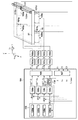
次に、支持装置である能動的除振装置60について説明する。この能動的除振装置60は、基礎または床等の設置面上に対象物である構造体31を支持するための複数の駆動部を有する。複数箇所とは例えば少なくとも4箇所であり、複数の駆動部は、例えば、少なくとも4つの能動的支持脚61により具体化される。図2に示されるように、複数の駆動部はそれぞれ、上下方向への駆動を可能にする空気ばね100a〜dを含む。変位センサ101a〜dは、複数の駆動部のうちの少なくとも一部に関してそれぞれ設けられ、それぞれが設置面70に対する構造体31の位置を計測する計測部である。制御アクチュエータ102a〜dは、空気ばね100a〜dの圧力を変化させ構造体31に駆動力を与える。ドライバ103a〜dは、制御アクチュエータ102a〜dに制御電流を与える。制御器104(制御部)は、変位センサ101a〜dの出力に基づいてドライバ103a〜dに制御信号を与える。制御器104において、モード分離器107(第1変換部)は、変位センサ101a〜dからの各位置の情報を、各モード成分(本実施形態の場合、Z、θx、θy、ねじれ(Torsion))に変換する。そして、これらの各モード成分に対するFBコントローラ108a〜dが、制御信号を生成する。
Next, the active
構造体31の重心位置に対する変位センサ101a〜dの(X,Y方向に対する)相対距離をsxa〜d, sya〜dとすると、モード分離器107(H1)は次式で表される。
(X, the Y direction) of the

モード分離器107(H1)は、次式に示されるように、変位センサ101a〜dの信号との積算により、各モード信号への変換を行う。
The mode separator 107 (H 1 ) performs conversion into each mode signal by integrating with the signals of the
こうして変換された情報に基づき決定された新たな位置、姿勢、及び形状の情報は、推力分配器106(第2変換部))により、各モード成分に対する制御信号、すなわち複数の駆動部に対する操作量の情報に変換される。これら各モード成分に対する制御信号は、推力分配器106により、ドライバ103a〜dに分配され、構造体31の姿勢が一定になるように、制御アクチュエータ102a〜dに指令が与えられる。構造体31の重心と制御アクチュエータ102a〜dの(X,Y方向に対する)相対距離をaxa〜d, aya〜dとすると、推力分配器106(H2)は次式で表わされる。
The information on the new position, orientation, and shape determined based on the information converted in this way is used by the thrust distributor 106 (second conversion unit)) to control signals for each mode component, that is, operation amounts for a plurality of drive units. Is converted to information. The control signal for each of these mode components is distributed to the drivers 103a to 103d by the
推力分配器106(H2)は、次式に示されるように、各モード成分の制御信号との積算により、ドライバ103a〜dの指令値への変換を行う。 The thrust distributor 106 (H 2 ) performs conversion into command values for the drivers 103a to 103d by integrating with the control signal of each mode component, as shown in the following equation.
制御器104内のメモリ105には、装置設置時に構造体31が設置面70に対し水平になるよう設定された値が格納されており、これらは目標値109a〜dとして使用される。本実施形態の制御器104は、剛体モード(第1制御モード)と弾性モード(第2制御モード)の2つの制御モードを有する。剛体モードは、構造体31の位置および姿勢のうちの少なくとも一方を制御し(すなわち、Z,θx,θy)且つ構造体31の形状を制御しない制御モードである。弾性モードは、構造体31の位置および姿勢の少なくとも一方(すなわち、Z,θx,θy)と、形状(例えば、ねじれ(Torsion))を制御する制御モードである。
The
能動的除振装置60のイニシャライズは次のように行われる。ここで、構造体31上に搭載されたマスクステージ20や基板ステージ30等の駆動ユニットは、予め定められた位置に配置されているものとする。まず初めに、剛体モードでフィードバック制御を行い、その状態での弾性モードの位置を観測する。すなわち、この剛体モードでの制御後に変位センサ101a〜dにより検出された構造体31の位置を観測する。その後、観測された構造体31の位置に基づいて、メモリ105に記憶された目標値109dが更新される。そして、制御モードを弾性モードに切り替えて、更新された目標値109dに対して位置フィードバック制御を実行する。
The active
この方法により、装置設置後に設置面70が沈降したとしても、構造体31の平面度を保った目標値109dに更新されるため、構造体31を変形させない位置制御を行うことができる。
By this method, even if the
また、キャリブレーション動作も同様の手順で行われる。任意のタイミングで、構造体31上の駆動ユニットを指定位置に配置し、一旦、剛体モードのみで能動的除振装置60の位置フィードバック制御を行う。その時の弾性モードの位置を観測し、その値を新たな目標値としてメモリ105の目標値109dを更新し、弾性モードの位置フィードバック制御を再開させる。
Also, the calibration operation is performed in the same procedure. The drive unit on the
このキャリブレーション動作により、装置イニシャライズ後、装置自重等の影響により経時的に設置面70が変形したとしても、構造体31の平面度を保つことができる。
By this calibration operation, the flatness of the
<第2実施形態>
第2実施形態に係る能動的除振装置60について説明する。この能動的除振装置60は、第1実施形態と同様、基礎または設置面70上に設置され、例えば4脚以上の能動的支持脚61により構造体31を支持している。図3に示されるように、構造体31は空気ばね100a〜dによって支持される。変位センサ101a〜cは、構造体31と設置面70との相対位置を検出する。すなわち、本実施形態では、構造体31を支持する少なくとも4箇所のうちの少なくとも3箇所における構造体31の位置を検出する。制御アクチュエータ102a〜dは、空気ばね100a〜dの圧力を変化させ構造体31に駆動力を与える。ドライバ103a〜dは、制御アクチュエータ102a〜dに制御電流を与える。制御器104は、変位センサ101a〜cからの検出信号に基づきドライバ103a〜dに制御信号を与える。制御器104において、モード分離器107は、変位センサ101a〜cからの信号を各モード成分(本実施形態の場合、Z、θx、θy)に変換する。そして、各モード成分に対するFBコントローラ108a〜dが、制御信号を生成する。
<Second Embodiment>
An active
構造体31の重心位置に対する変位センサ101a〜cの(X,Y方向に対する)相対距離をsxa〜c, sya〜cとすると、モード分離器107(H1)は次式で表される。
(X, the Y direction) of the
モード分離器107(H1)は、次式に示されるように、変位センサ101a〜cの信号との積算により、各モード信号への変換を行う。
The mode separator 107 (H 1 ) performs conversion into each mode signal by integrating with the signals of the
また、各モード成分に対する制御信号は、推力分配器106により、ドライバ103a〜dに分配され、構造体31の姿勢が一定になるように、制御アクチュエータ102a〜dに指令が与えられる。構造体31の重心と制御アクチュエータ102a〜dの(X,Y方向に対する)相対距離をaxa〜d, aya〜dとすると、推力分配器106(H2)は次式で表される。
Further, the control signal for each mode component is distributed to the drivers 103a to 103d by the
推力分配器106(H2)は、次式に示されるように、各モード成分の制御信号との積算により、ドライバ103a〜dの指令値への変換を行う。 The thrust distributor 106 (H 2 ) performs conversion into command values for the drivers 103a to 103d by integrating with the control signal of each mode component, as shown in the following equation.
制御器104内のメモリ105には、装置設置時に構造体31が設置面70に対し水平になるよう設定された値が格納されており、これらは目標値109a〜dとして使用される。本実施形態では、構造体31の弾性モード変位が顕著に表れる場所に検出用の支柱112a〜bが配置される。また、その先端に変位センサ111(第2検出部)が配置される。これにより、疑似的にターゲットとなる変形モードを検出し、直接、構造体31の変形量を検出する。変位センサ111には、例えばエンコーダ等の高精度なインクリメンタル方式のセンサが使用される。FBコントローラ108は、変位センサ111で検出された値を用いて制御信号を生成し、構造体31が変形しないよう制御アクチュエータ102a〜dに指令を与える。
The
能動的除振装置60のイニシャライズは次のように行われる。初めに、剛体モードのみで位置フィードバック制御を行い、その状態での弾性モードの位置を観測する。ただし、構造体31上に搭載されたマスクステージ20や基板ステージ30等の駆動ユニットは、予め定められた位置に配置されているものとする。観測された弾性モードの値は、新たな目標値として、メモリ105に記憶された目標値109dが更新される。弾性モードの位置フィードバック制御は、更新された目標値109dに対し行われる。
The active
この方法により、装置設置後に設置面70が沈降したとしても、構造体31の平面度を保った目標値109dに更新されるため、構造体31を変形させない位置制御を行うことができる。また、装置イニシャライズ後、経時的に設置面70が変形したとしても、構造体31の弾性モードを直接観測するセンサを使用した制御を行っているため、構造体31の平面度を保つことができる。
By this method, even if the
<他の応用例>
前述の実施形態に係る支持装置の適用例を説明する。当該支持装置は、種々の装置、例えば、ロボットや運輸、工作、加工、計測、製造に係る機械または装置(産業機械または装置)等において対象物(例えば定盤や基準物体)の支持に有用である。ここでは、一例として、産業機械としてのリソグラフィ装置(露光装置等)に備えられるステージ(XYステージ)装置への適用例を説明する。図4は、本適用例において当該支持装置が支持するステージ装置1000の構成例を示す図である。
<Other applications>
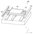
An application example of the supporting device according to the above-described embodiment will be described. The support device is useful for supporting an object (for example, a surface plate or a reference object) in various devices such as a robot, a machine or a device (industrial machine or device) related to transportation, work, processing, measurement, and manufacturing. is there. Here, as an example, an application example to a stage (XY stage) apparatus provided in a lithographic apparatus (exposure apparatus or the like) as an industrial machine will be described. FIG. 4 is a diagram showing a configuration example of the
なお、リソグラフィ装置は、パターンを基板に形成する装置であって、例えば、露光装置、描画装置、インプリント装置として具現化されうる。露光装置は、例えば、(極端)紫外光を用いて基板(上のレジスト)に(潜像)パターンを形成する。また、描画装置は、例えば、荷電粒子線(電子線等)を用いて基板(上のレジスト)に(潜像)パターンを形成する。また、インプリント装置は、基板上のインプリント材を成型して基板上にパターンを形成する。 The lithographic apparatus is an apparatus that forms a pattern on a substrate, and can be embodied as, for example, an exposure apparatus, a drawing apparatus, or an imprint apparatus. The exposure apparatus forms a (latent image) pattern on the substrate (resist on the top) using (extreme) ultraviolet light, for example. Further, the drawing apparatus forms a (latent image) pattern on the substrate (resist on the top) using, for example, a charged particle beam (electron beam or the like). Further, the imprint apparatus molds the imprint material on the substrate to form a pattern on the substrate.
ステージ装置1000は、図4に示すように、Y軸方向へのステージ1008(可動部)の移動に用いられるY軸モータ1009(駆動部)と、X軸方向へのステージ1008の移動に用いられるX軸モータ1012(駆動部)とを有する。ここで、両駆動部は、例えば、リニアモータと、当該リニアモータの可動子(またはそれとともに移動する可動部)の位置(または変位)を計測するための計測器(例えばエンコーダまたは干渉計)とを含んで構成されうる。
As shown in FIG. 4, the
<物品の製造方法の実施形態>
本発明の実施形態における物品の製造方法は、例えば、半導体デバイス等のマイクロデバイスや微細構造を有する素子等の物品を製造するのに好適である。本実施形態の物品の製造方法は、上記のリソグラフィ装置(露光装置やインプリント装置、描画装置など)を用いて基板に原版のパターンを転写する工程と、かかる工程でパターンが転写された基板を加工する工程とを含む。更に、かかる製造方法は、他の周知の工程(酸化、成膜、蒸着、ドーピング、平坦化、エッチング、レジスト剥離、ダイシング、ボンディング、パッケージング等)を含む。本実施形態の物品の製造方法は、従来の方法に比べて、物品の性能・品質・生産性・生産コストの少なくとも1つにおいて有利である。
<Embodiment of Method for Manufacturing Article>
The method of manufacturing an article according to the embodiment of the present invention is suitable for manufacturing an article such as a microdevice such as a semiconductor device or an element having a fine structure. The method of manufacturing an article according to the present embodiment includes a step of transferring a pattern of an original plate onto a substrate using the above-mentioned lithography apparatus (exposure apparatus, imprint apparatus, drawing apparatus, etc.) and a substrate on which the pattern is transferred in the step. And a step of processing. Further, the manufacturing method includes other well-known steps (oxidation, film formation, vapor deposition, doping, planarization, etching, resist stripping, dicing, bonding, packaging, etc.). The article manufacturing method of the present embodiment is advantageous in at least one of the performance, quality, productivity, and production cost of the article as compared with the conventional method.
(他の実施形態)
本発明は、上述の実施形態の1以上の機能を実現するプログラムを、ネットワーク又は記憶媒体を介してシステム又は装置に供給し、そのシステム又は装置のコンピュータにおける1つ以上のプロセッサーがプログラムを読出し実行する処理でも実現可能である。また、1以上の機能を実現する回路(例えば、ASIC)によっても実現可能である。
(Other embodiments)
The present invention supplies a program that implements one or more functions of the above-described embodiments to a system or apparatus via a network or a storage medium, and one or more processors in a computer of the system or apparatus read and execute the program. It can also be realized by the processing. It can also be realized by a circuit (for example, ASIC) that realizes one or more functions.
10:投影光学系、20:マスクステージ、30:基板ステージ、40:観察光学系、50:レーザ干渉計システム、60:能動的除振装置(支持装置) 10: Projection optical system, 20: Mask stage, 30: Substrate stage, 40: Observation optical system, 50: Laser interferometer system, 60: Active vibration isolation device (support device)
Claims (8)
前記複数の駆動部のうちの少なくとも一部に関してそれぞれ設けられ、それぞれが前記設置面に対する前記対象物の位置を計測する複数の計測部と、
前記複数の計測部の出力に基づいて前記複数の駆動部を制御する制御部と、
を含み、
前記制御部は、前記対象物の位置および姿勢のうちの少なくとも一方を制御し且つ前記対象物の形状を制御しない第1制御モードと、前記少なくとも一方と前記形状とを制御する第2制御モードとを有し、
前記制御部は、前記第1制御モードにおいて前記複数の計測部によりそれぞれ得られた複数の位置に基づいて前記第2制御モードにおける目標値を更新する
ことを特徴とする支持装置。 A plurality of drive units for supporting the object on the installation surface,
A plurality of measuring units, each of which is provided for at least a part of the plurality of driving units, each measuring the position of the object with respect to the installation surface,
A control unit that controls the plurality of drive units based on the outputs of the plurality of measurement units;
Including,
The control unit controls a first control mode that controls at least one of the position and the posture of the object and does not control the shape of the object, and a second control mode that controls the at least one and the shape. Have
The said control part updates the target value in the said 2nd control mode based on the some position respectively obtained by the said some measurement part in the said 1st control mode. The support apparatus characterized by the above-mentioned.
前記制御部は、
制御モードを前記第1制御モードにして、前記記憶部に記憶されている前記目標値に対して、前記複数の計測部の出力に基づく前記対象物のフィードバック制御を行い、
前記フィードバック制御の後に前記複数の計測部によりそれぞれ得られた複数の位置に基づいて、前記記憶部に記憶されている前記目標値を更新し、
制御モードを前記第2制御モードに切り替えて、前記記憶部に記憶されている前記更新された目標値に対して、前記複数の計測部の出力部に基づく前記対象物のフィードバック制御を行う
ことを特徴とする請求項1に記載の支持装置。 A storage unit that stores a target value of the position of the object with respect to the installation surface,
The control unit is
The control mode is set to the first control mode, the target value stored in the storage unit is subjected to feedback control of the object based on the outputs of the plurality of measurement units,
Based on the plurality of positions respectively obtained by the plurality of measuring units after the feedback control, update the target value stored in the storage unit,
Switching the control mode to the second control mode, and performing feedback control of the target object based on the output units of the plurality of measurement units with respect to the updated target value stored in the storage unit. The support device according to claim 1, characterized in that
前記複数の計測部により得られた前記複数の位置の情報を前記位置、前記姿勢および前記形状の情報に変換する第1変換部と、
前記第1変換部で変換されて得られた情報に基づいて得られた制御に係る前記位置、前記姿勢および前記形状の情報を前記複数の駆動部に対する操作量の情報に変換する第2変換部と、
を含むことを特徴とする請求項1乃至3のいずれか1項に記載の支持装置。 The control unit is
A first conversion unit that converts information on the plurality of positions obtained by the plurality of measurement units into information on the position, the posture, and the shape;
A second conversion unit that converts the information of the position, the posture, and the shape related to the control obtained based on the information obtained by the conversion by the first conversion unit into the information of the operation amount for the plurality of drive units. When,
The support device according to any one of claims 1 to 3, further comprising:
前記対象物の形状を計測する第2計測部を更に有し、
前記制御部は、
前記複数の計測部により得られた前記3箇所における前記対象物の位置の情報を前記位置および前記姿勢の情報に変換する第1変換部と、
前記第1変換部で変換されて得られた情報と前記第2計測部で得られた形状の情報とに基づいて得られた制御に係る前記位置、前記姿勢および前記形状の情報を前記複数の駆動部に対する操作量の情報に変換する第2変換部と、
を含むことを特徴とする請求項3に記載の支持装置。 Wherein the plurality of measurement unit is configured such that the plurality of drive unit to measure the position of the object with respect to three of the at least four positions for supporting the object,
Further comprising a second measuring unit for measuring the shape of the pre-Symbol object,
The control unit is
A first conversion unit that converts information on the position of the object at the three locations obtained by the plurality of measurement units into information on the position and the posture;
The information about the position, the posture, and the shape related to the control obtained based on the information obtained by the conversion by the first conversion unit and the information about the shape obtained by the second measurement unit is stored in the plurality of information items. A second conversion unit for converting information on an operation amount for the drive unit;
The support device according to claim 3, further comprising:
請求項1乃至6のうちいずれか1項に記載の支持装置と、
前記支持装置により支持された構造体と、
を含むことを特徴とするリソグラフィ装置。 A lithographic apparatus for patterning a substrate, comprising:
A support device according to any one of claims 1 to 6,
A structure supported by the supporting device,
A lithographic apparatus comprising:
前記工程で前記パターン形成を行われた前記基板を加工する工程と、
を含むことを特徴とする物品の製造方法。 Patterning a substrate using the lithographic apparatus according to claim 7;
A step of processing the substrate having the pattern formed in the step,
A method for producing an article, comprising:
Priority Applications (1)
| Application Number | Priority Date | Filing Date | Title |
|---|---|---|---|
| JP2015121425A JP6700680B2 (en) | 2015-06-16 | 2015-06-16 | Support apparatus, lithographic apparatus, and article manufacturing method |
Applications Claiming Priority (1)
| Application Number | Priority Date | Filing Date | Title |
|---|---|---|---|
| JP2015121425A JP6700680B2 (en) | 2015-06-16 | 2015-06-16 | Support apparatus, lithographic apparatus, and article manufacturing method |
Publications (2)
| Publication Number | Publication Date |
|---|---|
| JP2017010080A JP2017010080A (en) | 2017-01-12 |
| JP6700680B2 true JP6700680B2 (en) | 2020-05-27 |
Family
ID=57763531
Family Applications (1)
| Application Number | Title | Priority Date | Filing Date |
|---|---|---|---|
| JP2015121425A Active JP6700680B2 (en) | 2015-06-16 | 2015-06-16 | Support apparatus, lithographic apparatus, and article manufacturing method |
Country Status (1)
| Country | Link |
|---|---|
| JP (1) | JP6700680B2 (en) |
Family Cites Families (3)
| Publication number | Priority date | Publication date | Assignee | Title |
|---|---|---|---|---|
| TWI468880B (en) * | 2012-06-15 | 2015-01-11 | Asml Netherlands Bv | Positioning system, lithographic apparatus and device manufacturing method |
| JP2014022467A (en) * | 2012-07-13 | 2014-02-03 | Canon Inc | Exposure device, calibration method and article manufacturing method |
| JP2015082557A (en) * | 2013-10-22 | 2015-04-27 | キヤノン株式会社 | Exposure device |
-
2015
- 2015-06-16 JP JP2015121425A patent/JP6700680B2/en active Active
Also Published As
| Publication number | Publication date |
|---|---|
| JP2017010080A (en) | 2017-01-12 |
Similar Documents
| Publication | Publication Date | Title |
|---|---|---|
| CN101055425B (en) | Lithographic apparatus and device manufacturing method | |
| KR101325607B1 (en) | Stage apparatus, lithographic apparatus and method of positioning an object table | |
| US9477092B2 (en) | Optical imaging arrangement with individually actively supported components | |
| TWI418923B (en) | Positioning system, lithography device and method | |
| TWI395889B (en) | Damping object method, active damping system and lithography device | |
| US20050214657A1 (en) | Method of generating writing pattern data of mask and method of writing mask | |
| US9523569B2 (en) | Positioning apparatus, lithography apparatus, and article manufacturing method | |
| US20250123574A1 (en) | Actuator assemblies comprising piezo actuators or electrostrictive actuators | |
| JP2014120653A (en) | Positioning device, lithography apparatus, and method of manufacturing article using the same | |
| JP6363217B2 (en) | Control system, positioning system, lithographic apparatus, control method, device manufacturing method, and control program | |
| JP4386293B2 (en) | Vibration control apparatus, vibration control method, exposure apparatus, and device manufacturing method | |
| JP2014022467A (en) | Exposure device, calibration method and article manufacturing method | |
| JP6700680B2 (en) | Support apparatus, lithographic apparatus, and article manufacturing method | |
| JP2010522981A (en) | Split axis stage design for semiconductor applications | |
| JP6614880B2 (en) | Lithographic apparatus and article manufacturing method | |
| US9947508B2 (en) | Lithography apparatus, and method of manufacturing an article | |
| KR102592792B1 (en) | Stage device and method for calibrating object loading process | |
| KR102708128B1 (en) | Inspection apparatus, lithography apparatus, measuring method | |
| JP2010080861A (en) | Transfer apparatus and device manufacturing method | |
| JP2017037102A (en) | Support apparatus, lithographic apparatus, article manufacturing method, and industrial machine | |
| CN113544587A (en) | Object locator device and device manufacturing method | |
| JP2025167911A (en) | Exposure apparatus, exposure method, and article manufacturing method | |
| CN116157908A (en) | Marks projected onto objects during lithography process and method for designing marks | |
| JP2013125790A (en) | Holding device, exposure equipment, and device manufacturing method |
Legal Events
| Date | Code | Title | Description |
|---|---|---|---|
| A621 | Written request for application examination |
Free format text: JAPANESE INTERMEDIATE CODE: A621 Effective date: 20180608 |
|
| A977 | Report on retrieval |
Free format text: JAPANESE INTERMEDIATE CODE: A971007 Effective date: 20190513 |
|
| A131 | Notification of reasons for refusal |
Free format text: JAPANESE INTERMEDIATE CODE: A131 Effective date: 20190520 |
|
| A521 | Written amendment |
Free format text: JAPANESE INTERMEDIATE CODE: A523 Effective date: 20190718 |
|
| A131 | Notification of reasons for refusal |
Free format text: JAPANESE INTERMEDIATE CODE: A131 Effective date: 20191216 |
|
| A521 | Written amendment |
Free format text: JAPANESE INTERMEDIATE CODE: A523 Effective date: 20200207 |
|
| TRDD | Decision of grant or rejection written | ||
| A01 | Written decision to grant a patent or to grant a registration (utility model) |
Free format text: JAPANESE INTERMEDIATE CODE: A01 Effective date: 20200403 |
|
| A61 | First payment of annual fees (during grant procedure) |
Free format text: JAPANESE INTERMEDIATE CODE: A61 Effective date: 20200501 |
|
| R151 | Written notification of patent or utility model registration |
Ref document number: 6700680 Country of ref document: JP Free format text: JAPANESE INTERMEDIATE CODE: R151 |