JP6699438B2 - Wiring module - Google Patents
Wiring module Download PDFInfo
- Publication number
- JP6699438B2 JP6699438B2 JP2016156610A JP2016156610A JP6699438B2 JP 6699438 B2 JP6699438 B2 JP 6699438B2 JP 2016156610 A JP2016156610 A JP 2016156610A JP 2016156610 A JP2016156610 A JP 2016156610A JP 6699438 B2 JP6699438 B2 JP 6699438B2
- Authority
- JP
- Japan
- Prior art keywords
- unit
- wiring
- cover
- central
- connecting unit
- Prior art date
- Legal status (The legal status is an assumption and is not a legal conclusion. Google has not performed a legal analysis and makes no representation as to the accuracy of the status listed.)
- Active
Links
- 238000003860 storage Methods 0.000 claims description 22
- 230000008878 coupling Effects 0.000 description 11
- 238000010168 coupling process Methods 0.000 description 11
- 238000005859 coupling reaction Methods 0.000 description 11
- 210000000078 claw Anatomy 0.000 description 7
- 238000001514 detection method Methods 0.000 description 7
- 230000001012 protector Effects 0.000 description 6
- 230000005611 electricity Effects 0.000 description 5
- 238000000034 method Methods 0.000 description 5
- 238000005516 engineering process Methods 0.000 description 4
- 229910052751 metal Inorganic materials 0.000 description 4
- 239000002184 metal Substances 0.000 description 4
- 239000011347 resin Substances 0.000 description 4
- 229920005989 resin Polymers 0.000 description 4
- 238000003466 welding Methods 0.000 description 4
- 238000009434 installation Methods 0.000 description 3
- PXHVJJICTQNCMI-UHFFFAOYSA-N Nickel Chemical compound [Ni] PXHVJJICTQNCMI-UHFFFAOYSA-N 0.000 description 2
- 230000000694 effects Effects 0.000 description 2
- RYGMFSIKBFXOCR-UHFFFAOYSA-N Copper Chemical compound [Cu] RYGMFSIKBFXOCR-UHFFFAOYSA-N 0.000 description 1
- 229910000881 Cu alloy Inorganic materials 0.000 description 1
- ATJFFYVFTNAWJD-UHFFFAOYSA-N Tin Chemical compound [Sn] ATJFFYVFTNAWJD-UHFFFAOYSA-N 0.000 description 1
- 230000004308 accommodation Effects 0.000 description 1
- 229910052782 aluminium Inorganic materials 0.000 description 1
- XAGFODPZIPBFFR-UHFFFAOYSA-N aluminium Chemical compound [Al] XAGFODPZIPBFFR-UHFFFAOYSA-N 0.000 description 1
- 239000003990 capacitor Substances 0.000 description 1
- 229910052802 copper Inorganic materials 0.000 description 1
- 239000010949 copper Substances 0.000 description 1
- 238000002788 crimping Methods 0.000 description 1
- 239000000463 material Substances 0.000 description 1
- 229910052759 nickel Inorganic materials 0.000 description 1
- 230000000149 penetrating effect Effects 0.000 description 1
- 238000010248 power generation Methods 0.000 description 1
- 238000003825 pressing Methods 0.000 description 1
- 239000010935 stainless steel Substances 0.000 description 1
- 229910001220 stainless steel Inorganic materials 0.000 description 1
Images


Classifications
-
- H—ELECTRICITY
- H01—ELECTRIC ELEMENTS
- H01G—CAPACITORS; CAPACITORS, RECTIFIERS, DETECTORS, SWITCHING DEVICES OR LIGHT-SENSITIVE DEVICES, OF THE ELECTROLYTIC TYPE
- H01G11/00—Hybrid capacitors, i.e. capacitors having different positive and negative electrodes; Electric double-layer [EDL] capacitors; Processes for the manufacture thereof or of parts thereof
- H01G11/10—Multiple hybrid or EDL capacitors, e.g. arrays or modules
-
- H—ELECTRICITY
- H01—ELECTRIC ELEMENTS
- H01M—PROCESSES OR MEANS, e.g. BATTERIES, FOR THE DIRECT CONVERSION OF CHEMICAL ENERGY INTO ELECTRICAL ENERGY
- H01M10/00—Secondary cells; Manufacture thereof
- H01M10/42—Methods or arrangements for servicing or maintenance of secondary cells or secondary half-cells
- H01M10/48—Accumulators combined with arrangements for measuring, testing or indicating the condition of cells, e.g. the level or density of the electrolyte
- H01M10/482—Accumulators combined with arrangements for measuring, testing or indicating the condition of cells, e.g. the level or density of the electrolyte for several batteries or cells simultaneously or sequentially
-
- H—ELECTRICITY
- H01—ELECTRIC ELEMENTS
- H01M—PROCESSES OR MEANS, e.g. BATTERIES, FOR THE DIRECT CONVERSION OF CHEMICAL ENERGY INTO ELECTRICAL ENERGY
- H01M50/00—Constructional details or processes of manufacture of the non-active parts of electrochemical cells other than fuel cells, e.g. hybrid cells
- H01M50/20—Mountings; Secondary casings or frames; Racks, modules or packs; Suspension devices; Shock absorbers; Transport or carrying devices; Holders
- H01M50/298—Mountings; Secondary casings or frames; Racks, modules or packs; Suspension devices; Shock absorbers; Transport or carrying devices; Holders characterised by the wiring of battery packs
-
- H—ELECTRICITY
- H01—ELECTRIC ELEMENTS
- H01M—PROCESSES OR MEANS, e.g. BATTERIES, FOR THE DIRECT CONVERSION OF CHEMICAL ENERGY INTO ELECTRICAL ENERGY
- H01M50/00—Constructional details or processes of manufacture of the non-active parts of electrochemical cells other than fuel cells, e.g. hybrid cells
- H01M50/50—Current conducting connections for cells or batteries
- H01M50/502—Interconnectors for connecting terminals of adjacent batteries; Interconnectors for connecting cells outside a battery casing
- H01M50/503—Interconnectors for connecting terminals of adjacent batteries; Interconnectors for connecting cells outside a battery casing characterised by the shape of the interconnectors
-
- H—ELECTRICITY
- H01—ELECTRIC ELEMENTS
- H01M—PROCESSES OR MEANS, e.g. BATTERIES, FOR THE DIRECT CONVERSION OF CHEMICAL ENERGY INTO ELECTRICAL ENERGY
- H01M50/00—Constructional details or processes of manufacture of the non-active parts of electrochemical cells other than fuel cells, e.g. hybrid cells
- H01M50/50—Current conducting connections for cells or batteries
- H01M50/502—Interconnectors for connecting terminals of adjacent batteries; Interconnectors for connecting cells outside a battery casing
- H01M50/521—Interconnectors for connecting terminals of adjacent batteries; Interconnectors for connecting cells outside a battery casing characterised by the material
- H01M50/522—Inorganic material
-
- H—ELECTRICITY
- H01—ELECTRIC ELEMENTS
- H01M—PROCESSES OR MEANS, e.g. BATTERIES, FOR THE DIRECT CONVERSION OF CHEMICAL ENERGY INTO ELECTRICAL ENERGY
- H01M50/00—Constructional details or processes of manufacture of the non-active parts of electrochemical cells other than fuel cells, e.g. hybrid cells
- H01M50/50—Current conducting connections for cells or batteries
- H01M50/569—Constructional details of current conducting connections for detecting conditions inside cells or batteries, e.g. details of voltage sensing terminals
-
- H—ELECTRICITY
- H01—ELECTRIC ELEMENTS
- H01G—CAPACITORS; CAPACITORS, RECTIFIERS, DETECTORS, SWITCHING DEVICES OR LIGHT-SENSITIVE DEVICES, OF THE ELECTROLYTIC TYPE
- H01G11/00—Hybrid capacitors, i.e. capacitors having different positive and negative electrodes; Electric double-layer [EDL] capacitors; Processes for the manufacture thereof or of parts thereof
- H01G11/74—Terminals, e.g. extensions of current collectors
- H01G11/76—Terminals, e.g. extensions of current collectors specially adapted for integration in multiple or stacked hybrid or EDL capacitors
-
- H—ELECTRICITY
- H01—ELECTRIC ELEMENTS
- H01M—PROCESSES OR MEANS, e.g. BATTERIES, FOR THE DIRECT CONVERSION OF CHEMICAL ENERGY INTO ELECTRICAL ENERGY
- H01M10/00—Secondary cells; Manufacture thereof
- H01M10/42—Methods or arrangements for servicing or maintenance of secondary cells or secondary half-cells
- H01M10/425—Structural combination with electronic components, e.g. electronic circuits integrated to the outside of the casing
-
- Y—GENERAL TAGGING OF NEW TECHNOLOGICAL DEVELOPMENTS; GENERAL TAGGING OF CROSS-SECTIONAL TECHNOLOGIES SPANNING OVER SEVERAL SECTIONS OF THE IPC; TECHNICAL SUBJECTS COVERED BY FORMER USPC CROSS-REFERENCE ART COLLECTIONS [XRACs] AND DIGESTS
- Y02—TECHNOLOGIES OR APPLICATIONS FOR MITIGATION OR ADAPTATION AGAINST CLIMATE CHANGE
- Y02E—REDUCTION OF GREENHOUSE GAS [GHG] EMISSIONS, RELATED TO ENERGY GENERATION, TRANSMISSION OR DISTRIBUTION
- Y02E60/00—Enabling technologies; Technologies with a potential or indirect contribution to GHG emissions mitigation
- Y02E60/10—Energy storage using batteries
-
- Y—GENERAL TAGGING OF NEW TECHNOLOGICAL DEVELOPMENTS; GENERAL TAGGING OF CROSS-SECTIONAL TECHNOLOGIES SPANNING OVER SEVERAL SECTIONS OF THE IPC; TECHNICAL SUBJECTS COVERED BY FORMER USPC CROSS-REFERENCE ART COLLECTIONS [XRACs] AND DIGESTS
- Y02—TECHNOLOGIES OR APPLICATIONS FOR MITIGATION OR ADAPTATION AGAINST CLIMATE CHANGE
- Y02T—CLIMATE CHANGE MITIGATION TECHNOLOGIES RELATED TO TRANSPORTATION
- Y02T10/00—Road transport of goods or passengers
- Y02T10/60—Other road transportation technologies with climate change mitigation effect
- Y02T10/70—Energy storage systems for electromobility, e.g. batteries
Description
本明細書に開示された技術は、配線モジュールに関する。 The technique disclosed in the present specification relates to a wiring module.
従来、並べられた複数の電池に取り付けられる配線モジュールとして、特開2013−97962号公報に記載のものが知られている。この配線モジュールは、電池の電極同士に接続された電圧検知端子と、電圧検知端子に接続された検知電線と、検知電線が配索された絶縁プロテクタと、を有する。絶縁プロテクタは、複数の連結ユニットが連結されて構成されている。 BACKGROUND ART Conventionally, as a wiring module attached to a plurality of arranged batteries, one described in Japanese Patent Laid-Open No. 2013-97962 is known. This wiring module has a voltage detection terminal connected to the electrodes of the battery, a detection electric wire connected to the voltage detection terminal, and an insulating protector in which the detection electric wire is routed. The insulating protector is configured by connecting a plurality of connecting units.
各連結ユニットには検知電線を収容するための電線収容溝が設けられている。各連結ユニットが連結されると、各連結ユニットに形成された電線収容溝同士も連結される。 Each connecting unit is provided with an electric wire accommodation groove for accommodating a detection electric wire. When the connecting units are connected, the wire receiving grooves formed in the connecting units are also connected.
各連結ユニットは、係合部と、被係合部と、を備える。一の連結ユニットの嵌合片と、隣に配された他の連結ユニットの嵌合凹部とが嵌合することにより、複数の連結ユニットが連結されるようになっている。嵌合片は、複数の連結ユニットが連結する連結方向に沿って延びる構成となっている。また、嵌合凹部は、隣に配された一の連結ユニットの嵌合片と対応する位置に設けられて、嵌合片が内嵌されるようになっている。嵌合片、及び嵌合凹部は、連結ユニットのうち、電線収容溝とは異なった位置に設けられている。 Each connection unit includes an engaging portion and an engaged portion. By fitting the fitting piece of one connecting unit and the fitting recess of another connecting unit arranged next to each other, a plurality of connecting units are connected. The fitting piece is configured to extend along the connecting direction in which the plurality of connecting units are connected. Further, the fitting concave portion is provided at a position corresponding to the fitting piece of the adjacent one of the connecting units, and the fitting piece is fitted therein. The fitting piece and the fitting recess are provided at a position different from the electric wire housing groove in the connecting unit.
しかしながら、上記の構成によると、一の連結ユニットから他の連結ユニットへと延びる嵌合片を設けるスペースと、この嵌合片を内嵌するための嵌合凹部とを、各連結ユニットに設ける必要がある。そして、嵌合片と嵌合凹部とは、電線配索溝とは異なった位置に設けられている。このため、嵌合片と嵌合凹部とを設けるためのスペースによって、連結ユニット内において、検知電線の配索スペースが不足することが懸念される。 However, according to the above configuration, it is necessary to provide a space for providing a fitting piece extending from one connecting unit to another connecting unit and a fitting recess for internally fitting the fitting piece in each connecting unit. There is. Then, the fitting piece and the fitting recess are provided at positions different from the electric wire routing groove. For this reason, there is a concern that the space for providing the fitting piece and the fitting recess may cause a shortage of a space for arranging the detection wire in the connecting unit.
本明細書に開示された技術は上記のような事情に基づいて完成されたものであって、配線モジュールにおける電線の配索スペースを確保することを目的とする。 The technique disclosed in the present specification has been completed based on the above circumstances, and an object thereof is to secure a wiring space for electric wires in a wiring module.
本明細書に開示された技術は、並べられた複数の蓄電素子に取り付けられる配線モジュールであって、複数の電線と、前記複数の電線が配索される複数の連結ユニットと、を備え、前記複数の連結ユニットのうち第1連結ユニットは前記複数の電線の少なくとも1つが配される第1配索部を有し、前記複数の連結ユニットのうち前記第1連結ユニットと隣り合う第2連結ユニットは前記複数の電線の少なくとも1つが配される第2配索部を有し、前記第1配索部及び前記第2配索部の一方には係合部が設けられており、第1配索部及び前記第2配索部の他方には前記係合部に係合する係合受け部が設けられており、前記複数の連結ユニットは、前記係合部と前記係合受け部とが係合した状態で連結されており、前記第1連結ユニットには、第1連結ユニットに設けられた第1開口部を覆う第1カバーが、第1ヒンジ部を介して設けられており、前記第2連結ユニットには、第2連結ユニットに設けられた第2開口部を覆う第2カバーが、第2ヒンジ部を介して設けられており、前記第1カバー及び前記第2カバーの少なくとも一方にはユニットロック部が設けられており、前記第1カバーに前記ユニットロック部が設けられている場合には、前記第1カバーが前記第1開口部を覆った状態で前記ユニットロック部に係合するユニットロック受け部が、前記第2連結ユニットのうち前記第2カバー及び前記第2ヒンジ部と異なる部分に設けられており、前記第2カバーに前記ユニットロック部が設けられている場合には、前記第2カバーが前記第2開口部を覆った状態で前記ユニットロック部に係合するユニットロック受け部が、前記第1連結ユニットのうち前記第1カバー及び前記第1ヒンジ部と異なる部分に設けられている。 The technique disclosed in the present specification is a wiring module attached to a plurality of arranged power storage elements, and includes a plurality of electric wires and a plurality of connection units in which the plurality of electric wires are routed. A first connecting unit of the plurality of connecting units has a first wiring portion in which at least one of the plurality of electric wires is arranged, and a second connecting unit adjacent to the first connecting unit of the plurality of connecting units. Has a second wiring portion in which at least one of the plurality of electric wires is arranged, and one of the first wiring portion and the second wiring portion is provided with an engaging portion, and the first wiring portion is provided. An engagement receiving portion that engages with the engaging portion is provided on the other of the rope portion and the second wiring portion, and the plurality of connecting units include the engaging portion and the engaging receiving portion. The first connecting unit is connected in an engaged state, and the first connecting unit is provided with a first cover for covering a first opening provided in the first connecting unit via a first hinge portion. A second cover that covers the second opening provided in the second connecting unit is provided in the second connecting unit via a second hinge portion, and at least one of the first cover and the second cover is provided. Is provided with a unit lock portion, and when the first cover is provided with the unit lock portion, the first cover is engaged with the unit lock portion in a state where the first cover covers the first opening portion. In the case where a unit lock receiving portion to be fitted is provided in a portion of the second connecting unit different from the second cover and the second hinge portion, and the unit lock portion is provided in the second cover. Is different from the first cover and the first hinge portion of the first connecting unit in a unit lock receiving portion that engages with the unit lock portion in a state where the second cover covers the second opening portion. It is provided in the part .
上記の構成によれば、第1連結ユニットと第2連結ユニットとを連結するための第1係合部と第2係合受け部とは、それぞれ第1配索部及び第2配索部に設けられているので、配索部と異なる位置に係合部及び係合受け部が設けられている場合に比べて、配線モジュールにおける電線の配索スペースを十分に確保することができる。
また、上記の構成によれば、係合部と係合受け部とによって連結された第1連結ユニットと第2連結ユニットについて、さらに、第1カバー又は第2カバーによって二重係止することができる。この結果、第1連結ユニットと第2連結ユニットとを確実に連結することができる。
According to the above configuration, the first engaging portion and the second engaging receiving portion for connecting the first connecting unit and the second connecting unit to the first wiring portion and the second wiring portion, respectively. Since the wiring module is provided, it is possible to secure a sufficient wiring space for the electric wire in the wiring module, as compared with the case where the engagement portion and the engagement receiving portion are provided at positions different from the wiring portion.
According to the above configuration, the first connecting unit and the second connecting unit connected by the engaging portion and the engaging receiving portion can be further double-locked by the first cover or the second cover. it can. As a result, it is possible to reliably connect the first connecting unit and the second connecting unit.
本明細書に開示された技術の実施態様としては以下の態様が好ましい。 The following aspects are preferable as the embodiments of the technology disclosed in this specification.
前記第1配索部は溝状をなすと共に第1底壁を有しており、前記第1底壁には前記係合部及び前記係合受け部の一方が設けられており、前記第2配索部は溝状をなすと共に第2底壁を有しており、前記第2底壁には前記係合部及び前記係合受け部の他方が設けられていることが好ましい。 The first wiring portion has a groove shape and has a first bottom wall, and one of the engagement portion and the engagement receiving portion is provided on the first bottom wall, and the second wiring portion is provided. It is preferable that the routing portion has a groove shape and has a second bottom wall, and the second bottom wall is provided with the other of the engagement portion and the engagement receiving portion.
上記の態様によれば、電線の配索スペースの上下方向の高さ寸法が大きくなることを抑制することができる。 According to the above aspect, it is possible to prevent the height dimension of the wire installation space in the vertical direction from increasing.
前記第1連結ユニットと前記第2連結ユニットとが連結した状態で、前記係合部と前記係合受け部とは、前記第1底壁及び前記第2底壁の厚さ方向について重なっていることが好ましい。 In a state where the first connecting unit and the second connecting unit are connected, the engaging portion and the engaging receiving portion overlap each other in the thickness direction of the first bottom wall and the second bottom wall. It is preferable.
上記の態様によれば、電線の配索スペースの上下方向の高さ寸法が大きくなることを、一層抑制することができる。 According to the above aspect, it is possible to further suppress an increase in the vertical dimension of the wire installation space.
本明細書に開示された技術によれば、配線モジュールにおける電線の配索スペースを確保することができる。 According to the technique disclosed in this specification, it is possible to secure a space for arranging an electric wire in a wiring module.
<実施形態1>
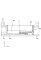
本明細書に開示された技術の実施形態1を、図1から図8を参照しつつ説明する。本実施形態に係る蓄電モジュール10は、電気自動車又はハイブリッド自動車等の車両(図示せず)に搭載されて、車両を駆動するための電源として使用される。蓄電モジュール10は、正極および負極の電極端子(図示せず)を備えた複数の蓄電素子12が並べて配された蓄電素子群13を有する。複数の電極端子間は、配線モジュール20によって電気的に接続されている(図1参照)。
<
A first embodiment of the technology disclosed in this specification will be described with reference to FIGS. 1 to 8. The
なお、以下の説明において、Z方向を上方とし、Y方向を前方とし、X方向を右方として説明する。また、複数の同一部材については、一の部材に符号を付し、他の部材については符号を省略することがある。 In the following description, the Z direction will be referred to as upward, the Y direction will be referred to as front, and the X direction will be referred to as right. Further, regarding a plurality of the same members, one member may be denoted by a reference numeral, and other members may be omitted.
(蓄電素子12)
図1に示すように、蓄電素子12は扁平な略直方体形状をなしている。蓄電素子12の内部には図示しない発電要素が収容されている。蓄電素子12の上面には、長手方向の両端部寄りの位置に、一対の電極端子(図示せず)が上方に突出して形成されている。電極端子の一方は正極端子であり、他方は負極端子である。正極端子を構成する電極端子と、負極端子を構成する電極端子とは同形、同大である。電極端子は、金属製の端子台(図示せず)から上方に向かって丸棒状に突出する電極ポスト(図示せず)を備え、その電極ポストの外面にはねじ山が形成されている。蓄電素子12は、隣り合う電極端子が異なる極性となるように配置されている。複数の蓄電素子12は図中左右方向に並べられて蓄電素子群13とされている。
(Power storage element 12)
As shown in FIG. 1, the
(配線モジュール20)
図2に示すように、配線モジュール20は、蓄電素子12の正極および負極の電極端子の電極ポストにそれぞれ挿通されて接続される一対の端子貫通孔22を有する金属製の複数のバスバー21と、バスバー21を保持する複数の連結ユニット31と、を備える。なお、図2中、2つのバスバー21を記載し、他のバスバー21は省略した。
(Wiring module 20)
As shown in FIG. 2, the
(バスバー21)
バスバー21は、銅、銅合金、ステンレス鋼(SUS)、アルミニウム等からなる金属製の板材を所定の形状にプレス加工することにより形成され、図2に示すように、全体として略長方形状をなしている。バスバー21の表面には、スズ、ニッケル等の金属がメッキされていてもよい。バスバー21には、電極端子の電極ポストが挿通される円形状をなす一対の端子貫通孔22,22が、バスバー21を貫通して形成されている。この端子貫通孔22は、電極ポストの径よりも若干大きく設定されている。端子貫通孔22内に電極ポストが貫通された状態でナット(図示せず)が螺合されて、ナットと端子台との間にバスバー21が挟まれることにより、電極端子とバスバー21とが電気的に接続される。
(Bus bar 21)
The
バスバー21は一対の長辺を有する。一対の長辺のうち一の長辺には、外方に突出する電線接続部23が設けられている。電線接続部23には電線60の端部が接続されている。これにより、バスバー21と電線60とが電気的に接続されている。この電線60は蓄電素子12の電圧を検知する電圧検知線である。電線接続部23と電線60とは、圧着、圧接、超音波溶接、レーザー溶接、抵抗溶接等、公知の手法により接続することができる。
The
(連結ユニット31)
連結ユニット31が連結方向(本実施形態ではX軸方向)に沿って複数個連結されることにより、樹脂プロテクタ30が構成されている。樹脂プロテクタ30は、左右方向に細長い形状をなしている。連結ユニット31は、図2の平面図に示すように、上方に開口すると共にバスバー21を収容し保持する保持部32(開口部の一例)と、バスバー21に接続された電線60を収容するための配索部35とが、樹脂プロテクタ30の長手方向に沿って設けられている。保持部32は上下方向に開口して形成されている。これにより、バスバー21の下方において、バスバー21と蓄電素子12の端子台とを接触させることができるようになっていると共に、バスバー21の上方から、電極ポストにナットを螺合させることができるようになっている。詳細には図示しないが、保持部32には、複数のバスバー21が互いに絶縁された状態で左右方向に並んで保持されている。
(Connecting unit 31)
The
連結ユニット31は、図2における左端部に配された左連結ユニット31A(第1連結ユニットの一例)と、右端部に配された右連結ユニット31C(第1連結ユニットの一例)と、左連結ユニット31Aと右連結ユニット31Cとの間に配された中央連結ユニット31B(第2連結ユニットの一例)と、を含む。以下の説明において、左連結ユニット31A、中央連結ユニット31B,及び右連結ユニット31Cについてまとめて説明する場合には、連結ユニット31として説明することがある。
The
左連結ユニット31Aに設けられた配索部35は左配索部35A(第1配索部の一例)とされ、右連結ユニット31Cに設けられた配索部35は右配索部35C(第1配索部の一例)とされ、中央連結ユニット31Bに設けられた配索部35は中央配索部35B(第2配索部の一例)とされる。以下の説明において、左配索部35A、中央配索部35B、及び右配索部35Cについてまとめて説明する場合には、配索部35として説明することがある。
The
配索部35は、保持部32の並び方向(左右方向)に沿って設けられている。複数の連結ユニット31が連結されることにより、各連結ユニット31に形成された配索部35同士が連結されるようになっている。
The
左連結ユニット31Aの左配索部35Aは、左底壁34A(第1底壁の一例)と、左底壁34Aの両側縁に立ち上がって形成された側壁33Aを有する。右連結ユニット31Cの右配索部35Cは、右底壁34C(第1底壁の一例)と、右底壁34Cの両側縁に立ち上がって形成された側壁33Cを有する。中央連結ユニット31Bの中央配索部35Bは、中央底壁34B(第1底壁の一例)と、中央底壁34Bの両側縁に立ち上がって形成された側壁33Bを有する。
The
(左連結ユニット31Aと、中央連結ユニット31B)
図3に示すように、左底壁34Aの右端部(中央連結ユニット31B側の端部)には、右方に突出する左係合部40A(係合部の一例)が設けられている。左係合部40Aは、上方から見て略長方形状をしている。左係合部40Aの下面には、下方に突出する爪部41Aが形成されている。
(Left connecting
As shown in FIG. 3, a
図3に示すように、中央底壁34Bの左端部(左連結ユニット31Aの端部)には、左方に突出する中央係合受け部42B(係合受け部の一例)が設けられている。中央係合受け部42Bは、上方から見て、左係合部40Aよりもやや小さな略長方形状をしている。中央係合受け部42Bの上面には、上方に突出すると共に、左係合部40Aに設けられた爪部41Aに係合する爪部41Bが形成されている。
As shown in FIG. 3, a central
図5及び図7に示すように、中央底壁34Bの左端部には、前部及び後部に、左係合部40Aに対して上方から重なる重なり部43が形成されている。重なり部43は上方から見て略長方形状をなしている。重なり部43の中央付近は、下方に膨出されており、左係合部40Aの上面に確実に重なるようになっている。
As shown in FIGS. 5 and 7, an overlapping
左連結ユニット31Aと、中央連結ユニット31Bとが連結された状態においては、左係合部40Aと中央係合受け部42Bとは、左底壁34A及び中央底壁34Bの厚さ方向(上下方向)について重なり合っている。また、上記したように、中央連結ユニット31Bの重なり部43は、左係合部40Aの右端部における前後両端部に、上から重なっている。
In the state where the
図6に示すように、左係合部40Aの爪部41Aは、中央係合受け部42Bの爪部41Bに対して、右方から係合するようになっている。これにより、左連結ユニット31Aと、中央連結ユニット31Bとが、左右方向について抜け止めされるようになっている。そして、左係合部40Aに対して上方から重なり部43が重なっているので、左係合部40Aの爪部41Aと、中央係合受け部42Bの爪部41Bとの係合が外れることが抑制されるようになっている。
As shown in FIG. 6, the
図6に示すように、左係合部40Aは、左底壁34Aと略平行に延びて形成されている。また、中央係合受け部42Bは、中央底壁34Bと略平行に延びて形成されている。これにより、左係合部40Aと中央係合受け部42Bとが係合した状態における上下方向の厚さ寸法が増大することが抑制されている。
As shown in FIG. 6, the
左連結ユニット31Aと、中央連結ユニット31Bとが連結された状態において、左連結ユニット31Aの側壁33Aの上端部の高さ位置と、中央連結ユニット31Bの側壁33Bの上端部の高さ位置とは、略同じに揃えられている。
When the
複数の電線60は、左底壁34Aと、左係合部40Aと、中央底壁34Bと、を下縁部とし、側壁33A及び側壁33Bの上端縁を上縁部とした領域内に配索されている。図6中、上下方向の高さ寸法Hの範囲内に複数の電線60が配索されるようになっている。
The plurality of
図2に示すように、左連結ユニット31Aの前縁部、及び後縁部には、左ヒンジ部44A(第1ヒンジ部の一例)を介して、左カバー45A(第1カバーの一例)が、左ヒンジ部44Aを軸として回動可能に設けられている。左カバー45Aには、左ヒンジ部44Aと反対側の端縁に、複数の左カバーロック部46Aが左右方向に間隔を開けて設けられている。この左カバーロック部46Aは、左配索部35Aのうち電線60が配索される領域内に設けられた左カバーロック受け部47Aと弾性的に係合するようになっている。左カバーロック部46Aと、左カバーロック受け部47Aとが係合することにより、左カバー45Aは、左連結ユニット31Aの保持部32を上方から塞ぐようになっている。
As shown in FIG. 2, a
図2に示すように、中央連結ユニット31Bの前縁部、及び後縁部には、中央ヒンジ部44B(第2ヒンジ部の一例)を介して、中央カバー45B(第2カバーの一例)が、中央ヒンジ部44Bを軸として回動可能に設けられている。中央カバー45Bには、中央ヒンジ部44Bと反対側の端縁に、複数の中央カバーロック部46Bが左右方向に間隔を開けて設けられている。この中央カバーロック部46Bは、中央配索部35Bのうち電線60が配索される領域内に設けられた中央カバーロック受け部47Bと弾性的に係合するようになっている。中央カバーロック部46Bと、中央カバーロック受け部47Bとが係合することにより、中央カバー45Bは、中央連結ユニット31Bの保持部32を上方から塞ぐようになっている。
As shown in FIG. 2, a
中央連結ユニット31Bの前縁部、及び後縁部に設けられた中央カバー45Bの左端部には、それぞれ、中央ユニットロック部48B(ユニットロック部の一例)が設けられている。この中央ユニットロック部48Bは、左連結ユニット31Aの左配索部35Aの右端部のうち、電線60が配索される領域内に設けられた左ユニットロック受け部49A(ロック受け部の一例)と弾性的に係合することにより、左連結ユニット31Aと、中央連結ユニット31Bとを連結するようになっている(図8参照)。
A central
(中央連結ユニット31Bと、右連結ユニット31C)
右連結ユニット31Cは、左連結ユニット31Aと左右対称に形成されている。このため、上記した、左連結ユニット31Aと中央連結ユニット31Bとに関する記述において、方向に関する記述について「右」と「左」とを置き換え、符号について「A」を「C」と置き換えることにより、中央連結ユニット31Bと、右連結ユニット31Cの構成についての説明とすることができる。このため、中央連結ユニット31Bと、右連結ユニット31Cの構成についての説明は省略する。なお、図には、右連結ユニット31Cに係る部材について、上記のルールに則って符号が付されている。
(
The
(実施形態の作用、効果)
続いて、本実施形態の作用、効果について説明する。本実施形態は、並べられた複数の蓄電素子12に取り付けられる配線モジュール20であって、複数の電線60と、複数の電線60が配索される複数の連結ユニット31と、を備え、複数の連結ユニット31のうち左連結ユニット31Aは複数の電線60の少なくとも1つが配される左配索部35Aを有し、複数の連結ユニット31のうち左連結ユニット31Aと隣り合う中央連結ユニット31Bは複数の電線60の少なくとも1つが配される中央配索部35Bを有し、左配索部35Aには左係合部40Aが設けられており、中央配索部35Bには左係合部40Aに係合する中央係合受け部42Bが設けられており、複数の連結ユニット31は、左係合部40Aと中央係合受け部42Bとが係合した状態で連結されている。
(Operation and effect of the embodiment)
Next, the operation and effect of this embodiment will be described. The present embodiment is a
本実施形態によれば、左連結ユニット31Aと中央連結ユニット31Bとを連結するための左係合部40Aと中央係合受け部42Bとは、それぞれ左配索部35A及び中央配索部35Bに設けられているので、配索部35と異なる位置に係合部及び係合受け部が設けられている場合に比べて、配線モジュール20における電線60の配索スペースを十分に確保することができる。
According to this embodiment, the
また、本実施形態においては、左配索部35Aは溝状をなすと共に左底壁34Aを有しており、左底壁34Aには左係合部40Aが設けられており、中央配索部35Bは溝状をなすと共に中央底壁34Bを有しており、中央底壁34Bには中央係合受け部42Bが設けられている。これにより、電線60の配索スペースの上下方向の高さ寸法が大きくなることを抑制することができる。
Further, in the present embodiment, the
また、本実施形態によれば、左連結ユニット31Aと中央連結ユニット31Bとが連結した状態で、左係合部40Aと中央係合受け部42Bとは、左底壁34A及び中央底壁34Bの厚さ方向について重なっている。これにより、電線60の配索スペースの上下方向の高さ寸法が大きくなることを、一層抑制することができる。
Further, according to the present embodiment, in the state where the
また、本実施形態によれば、左連結ユニット31Aには、左連結ユニット31Aに設けられた保持部32を覆う左カバー45Aが、左ヒンジ部44Aを介して設けられており、中央連結ユニット31Bには、中央連結ユニット31Bに設けられた保持部32を覆う中央カバー45Bが、中央ヒンジ部44Bを介して設けられており、中央カバー45Bには中央ユニットロック部48Bが設けられており、中央カバー45Bが保持部32を覆った状態で中央ユニットロック部48Bに係合する左ユニットロック受け部49Aが、左連結ユニット31Aに設けられている。
Further, according to the present embodiment, the
上記の構成により、中央カバー45Bによって、左連結ユニット31Aと中央連結ユニット31Bとを二重係止することができる。この結果、左連結ユニット31Aと中央連結ユニット31Bとを確実に連結することができる。
With the above configuration, the
<他の実施形態>
本明細書に開示された技術は上記記述及び図面によって説明した実施形態に限定されるものではなく、例えば次のような実施形態も本明細書に開示された技術の技術的範囲に含まれる。
<Other Embodiments>
The technology disclosed in the present specification is not limited to the embodiments described by the above description and the drawings, and the following embodiments are also included in the technical scope of the technology disclosed in the present specification.
(1)本実施形態においては、左底壁34Aに左係合部40Aが設けられており、中央底壁34Bに中央係合受け部42Bが設けられていたが、これに限られず、中央底壁34Bに係合部が設けられ、左底壁34Aに係合受け部が設けられる構成としてもよい。
(1) In the present embodiment, the
(2)本実施形態においては、左底壁34Aに左係合部40Aが設けられており、中央底壁34Bに中央係合受け部42Bが設けられていたが、これに限られず、側壁33Aに係合部が設けられており、側壁33Bに係合受け部が設けられる構成としてもよいし、側壁33Bに係合部が設けられており、側壁33Aに係合受け部が設けられる構成としてもよい。
(2) In the present embodiment, the
(3)本実施形態においては、左カバー45Aによって左連結ユニット31Aの保持部32が覆われ、中央カバー45Bによって中央連結ユニット31Bの保持部32が覆われる構成としたが、これに限られず、左カバー45A及び中央カバー45Bは省略してもよい。また、左カバー45A及び中央カバー45Bによって配索部35が覆われる構成としてもよい。また、別体のカバーを配線モジュール20に組み付けることによって配索部35が覆われる構成としてもよい。
(3) In the present embodiment, the
(4)本実施形態においては、左連結ユニット31A、中央連結ユニット31B、及び右連結ユニット31Cの3つの連結ユニット31が連結する構成としたが、これに限られず、2つの連結ユニット31が連結する構成としてもよいし、4つ以上の連結ユニット31が連結する構成としてもよい。複数の連結ユニットのうち、隣り合う2つの連結ユニットを第1ユニット及び第2ユニットとすることができる。
(4) In the present embodiment, the three
(5)本実施形態においては、複数の蓄電素子12は直列に接続される構成としたが、これに限られず、複数の蓄電素子12は並列に接続される構成としてもよい。
(5) In the present embodiment, the plurality of
(6)本実施形態においては、蓄電素子12として二次電池を用いたが、これに限られず、キャパシタを用いてもよい。
(6) In the present embodiment, the secondary battery is used as the
12:蓄電素子
20:配線モジュール
31A:左連結ユニット
31B:中央連結ユニット
31C:右連結ユニット
34A:左底壁
34B:中央底壁
34C:右底壁
35A:左配索部
35B:中央配索部
35C:右配索部
40A:左係合部
42B:中央係合受け部
44A:左ヒンジ部
44B:中央ヒンジ部
44C:右ヒンジ部
45A:左カバー
45B:中央カバー
45C:右カバー
48B:中央ユニットロック部
49A:左ユニットロック受け部
60:電線
12: Electric storage element 20:
Claims (3)
複数の電線と、
前記複数の電線が配索される複数の連結ユニットと、を備え、
前記複数の連結ユニットのうち第1連結ユニットは前記複数の電線の少なくとも1つが配される第1配索部を有し、
前記複数の連結ユニットのうち前記第1連結ユニットと隣り合う第2連結ユニットは前記複数の電線の少なくとも1つが配される第2配索部を有し、
前記第1配索部及び前記第2配索部の一方には係合部が設けられており、第1配索部及び前記第2配索部の他方には前記係合部に係合する係合受け部が設けられており、
前記複数の連結ユニットは、前記係合部と前記係合受け部とが係合した状態で連結されており、
前記第1連結ユニットには、第1連結ユニットに設けられた第1開口部を覆う第1カバーが、第1ヒンジ部を介して設けられており、
前記第2連結ユニットには、第2連結ユニットに設けられた第2開口部を覆う第2カバーが、第2ヒンジ部を介して設けられており、
前記第1カバー及び前記第2カバーの少なくとも一方にはユニットロック部が設けられており、
前記第1カバーに前記ユニットロック部が設けられている場合には、前記第1カバーが前記第1開口部を覆った状態で前記ユニットロック部に係合するユニットロック受け部が、前記第2連結ユニットのうち前記第2カバー及び前記第2ヒンジ部と異なる部分に設けられており、
前記第2カバーに前記ユニットロック部が設けられている場合には、前記第2カバーが前記第2開口部を覆った状態で前記ユニットロック部に係合するユニットロック受け部が、前記第1連結ユニットのうち前記第1カバー及び前記第1ヒンジ部と異なる部分に設けられている、配線モジュール。 A wiring module attached to a plurality of arranged power storage elements,
Multiple wires,
A plurality of connection units in which the plurality of electric wires are routed,
The first connecting unit of the plurality of connecting units has a first wiring portion in which at least one of the plurality of electric wires is arranged,
The second connecting unit adjacent to the first connecting unit among the plurality of connecting units has a second wiring portion in which at least one of the plurality of electric wires is arranged,
An engagement portion is provided on one of the first wiring portion and the second wiring portion, and the other portion of the first wiring portion and the second wiring portion is engaged with the engagement portion. An engagement receiving part is provided,
The plurality of connecting units are connected in a state where the engaging portion and the engaging receiving portion are engaged ,
The first connecting unit is provided with a first cover that covers a first opening provided in the first connecting unit via a first hinge portion,
A second cover that covers the second opening provided in the second connection unit is provided in the second connection unit via a second hinge portion,
A unit lock portion is provided on at least one of the first cover and the second cover,
When the unit lock portion is provided on the first cover, the unit lock receiving portion that engages with the unit lock portion in a state in which the first cover covers the first opening is the second lock. The connecting unit is provided at a portion different from the second cover and the second hinge portion,
When the unit lock portion is provided on the second cover, the unit lock receiving portion that engages with the unit lock portion in a state in which the second cover covers the second opening is the first lock. A wiring module provided in a portion of the connection unit different from the first cover and the first hinge portion .
前記第2配索部は溝状をなすと共に第2底壁を有しており、前記第2底壁には前記係合部及び前記係合受け部の他方が設けられている、
請求項1に記載の配線モジュール。 The first wiring portion has a groove-like shape and has a first bottom wall, and the first bottom wall is provided with one of the engagement portion and the engagement receiving portion,
The second wiring portion has a groove shape and has a second bottom wall, and the second bottom wall is provided with the other of the engagement portion and the engagement receiving portion.
The wiring module according to claim 1.
Priority Applications (4)
| Application Number | Priority Date | Filing Date | Title |
|---|---|---|---|
| JP2016156610A JP6699438B2 (en) | 2016-08-09 | 2016-08-09 | Wiring module |
| US16/323,428 US10923292B2 (en) | 2016-08-09 | 2017-07-24 | Wiring module |
| CN201780047585.4A CN109565023B (en) | 2016-08-09 | 2017-07-24 | Wiring module |
| PCT/JP2017/026630 WO2018030131A1 (en) | 2016-08-09 | 2017-07-24 | Wiring module |
Applications Claiming Priority (1)
| Application Number | Priority Date | Filing Date | Title |
|---|---|---|---|
| JP2016156610A JP6699438B2 (en) | 2016-08-09 | 2016-08-09 | Wiring module |
Publications (3)
| Publication Number | Publication Date |
|---|---|
| JP2018026237A JP2018026237A (en) | 2018-02-15 |
| JP2018026237A5 JP2018026237A5 (en) | 2019-02-21 |
| JP6699438B2 true JP6699438B2 (en) | 2020-05-27 |
Family
ID=61162239
Family Applications (1)
| Application Number | Title | Priority Date | Filing Date |
|---|---|---|---|
| JP2016156610A Active JP6699438B2 (en) | 2016-08-09 | 2016-08-09 | Wiring module |
Country Status (4)
| Country | Link |
|---|---|
| US (1) | US10923292B2 (en) |
| JP (1) | JP6699438B2 (en) |
| CN (1) | CN109565023B (en) |
| WO (1) | WO2018030131A1 (en) |
Families Citing this family (2)
| Publication number | Priority date | Publication date | Assignee | Title |
|---|---|---|---|---|
| JP7184606B2 (en) * | 2018-11-20 | 2022-12-06 | 日本メクトロン株式会社 | Support member and battery module |
| JP7182094B2 (en) * | 2020-02-27 | 2022-12-02 | 矢崎総業株式会社 | busbar module |
Family Cites Families (8)
| Publication number | Priority date | Publication date | Assignee | Title |
|---|---|---|---|---|
| JP5813302B2 (en) | 2009-09-07 | 2015-11-17 | 矢崎総業株式会社 | Bus bar module and power supply device including the bus bar module |
| JP5550291B2 (en) * | 2009-09-17 | 2014-07-16 | 矢崎総業株式会社 | Electric wire arrangement, bus bar module, and power supply device |
| JP5734607B2 (en) * | 2010-09-16 | 2015-06-17 | 矢崎総業株式会社 | Battery connection member |
| JP5673491B2 (en) | 2011-10-31 | 2015-02-18 | 株式会社オートネットワーク技術研究所 | Battery wiring module |
| JP5772524B2 (en) | 2011-11-11 | 2015-09-02 | 株式会社オートネットワーク技術研究所 | Battery wiring module |
| JP5757252B2 (en) * | 2012-02-08 | 2015-07-29 | 株式会社オートネットワーク技術研究所 | Wiring module |
| JP5978037B2 (en) * | 2012-07-20 | 2016-08-24 | 矢崎総業株式会社 | Bus bar module |
| JP6158500B2 (en) * | 2012-11-28 | 2017-07-05 | 矢崎総業株式会社 | Bus bar module structure |
-
2016
- 2016-08-09 JP JP2016156610A patent/JP6699438B2/en active Active
-
2017
- 2017-07-24 WO PCT/JP2017/026630 patent/WO2018030131A1/en active Application Filing
- 2017-07-24 CN CN201780047585.4A patent/CN109565023B/en active Active
- 2017-07-24 US US16/323,428 patent/US10923292B2/en active Active
Also Published As
| Publication number | Publication date |
|---|---|
| CN109565023A (en) | 2019-04-02 |
| JP2018026237A (en) | 2018-02-15 |
| US20190355527A1 (en) | 2019-11-21 |
| CN109565023B (en) | 2021-08-20 |
| WO2018030131A1 (en) | 2018-02-15 |
| US10923292B2 (en) | 2021-02-16 |
Similar Documents
| Publication | Publication Date | Title |
|---|---|---|
| JP4665277B2 (en) | Battery device | |
| JP5741230B2 (en) | Battery wiring module | |
| JP5269018B2 (en) | Battery pack and bus bar holder | |
| EP2827405B1 (en) | Battery wiring module | |
| JP6699464B2 (en) | Connection module | |
| JP6205808B2 (en) | Storage element module | |
| US20160036029A1 (en) | Power source pack | |
| US10431786B2 (en) | Electricity storage module | |
| JP6143108B2 (en) | Power storage module | |
| JP2013016381A (en) | Battery wiring module | |
| WO2017047258A1 (en) | Battery pack | |
| JP6629140B2 (en) | Power storage module | |
| JP6243624B2 (en) | Bus bar module and power supply | |
| JP5757252B2 (en) | Wiring module | |
| EP3367473B1 (en) | Wiring module | |
| CN111149234A (en) | Electrically connected component housing case and battery module | |
| JP5447724B1 (en) | Wiring module | |
| JP2013080693A (en) | Wiring module for battery | |
| US11005143B2 (en) | Wiring module | |
| JP2017130289A (en) | Power storage device | |
| JP6593166B2 (en) | Wiring module | |
| WO2015163113A1 (en) | Wiring module | |
| JP6699438B2 (en) | Wiring module | |
| JP2013206840A (en) | Connection structure for voltage detection terminal | |
| WO2014057755A1 (en) | Power storage module |
Legal Events
| Date | Code | Title | Description |
|---|---|---|---|
| A621 | Written request for application examination |
Free format text: JAPANESE INTERMEDIATE CODE: A621 Effective date: 20181126 |
|
| A521 | Request for written amendment filed |
Free format text: JAPANESE INTERMEDIATE CODE: A523 Effective date: 20190108 |
|
| A131 | Notification of reasons for refusal |
Free format text: JAPANESE INTERMEDIATE CODE: A131 Effective date: 20191010 |
|
| A521 | Request for written amendment filed |
Free format text: JAPANESE INTERMEDIATE CODE: A523 Effective date: 20191119 |
|
| TRDD | Decision of grant or rejection written | ||
| A01 | Written decision to grant a patent or to grant a registration (utility model) |
Free format text: JAPANESE INTERMEDIATE CODE: A01 Effective date: 20200331 |
|
| A61 | First payment of annual fees (during grant procedure) |
Free format text: JAPANESE INTERMEDIATE CODE: A61 Effective date: 20200413 |
|
| R150 | Certificate of patent or registration of utility model |
Ref document number: 6699438 Country of ref document: JP Free format text: JAPANESE INTERMEDIATE CODE: R150 |
|
| R250 | Receipt of annual fees |
Free format text: JAPANESE INTERMEDIATE CODE: R250 |