JP6699093B2 - Spinneret for electrostatic spinning - Google Patents
Spinneret for electrostatic spinning Download PDFInfo
- Publication number
- JP6699093B2 JP6699093B2 JP2015098719A JP2015098719A JP6699093B2 JP 6699093 B2 JP6699093 B2 JP 6699093B2 JP 2015098719 A JP2015098719 A JP 2015098719A JP 2015098719 A JP2015098719 A JP 2015098719A JP 6699093 B2 JP6699093 B2 JP 6699093B2
- Authority
- JP
- Japan
- Prior art keywords
- raw material
- spinneret
- material fluid
- electrospinning
- nanofibers
- Prior art date
- Legal status (The legal status is an assumption and is not a legal conclusion. Google has not performed a legal analysis and makes no representation as to the accuracy of the status listed.)
- Active
Links
- 238000010041 electrostatic spinning Methods 0.000 title claims description 33
- 239000012530 fluid Substances 0.000 claims description 159
- 239000002994 raw material Substances 0.000 claims description 155
- 238000001523 electrospinning Methods 0.000 claims description 89
- 238000009826 distribution Methods 0.000 claims description 47
- 238000009987 spinning Methods 0.000 claims description 43
- 230000000149 penetrating effect Effects 0.000 claims description 13
- 239000007769 metal material Substances 0.000 claims description 7
- 238000007599 discharging Methods 0.000 claims description 3
- 239000002121 nanofiber Substances 0.000 description 85
- 239000000835 fiber Substances 0.000 description 31
- 229920005569 poly(vinylidene fluoride-co-hexafluoropropylene) Polymers 0.000 description 28
- 230000005684 electric field Effects 0.000 description 18
- 239000000463 material Substances 0.000 description 13
- ZMXDDKWLCZADIW-UHFFFAOYSA-N N,N-Dimethylformamide Chemical compound CN(C)C=O ZMXDDKWLCZADIW-UHFFFAOYSA-N 0.000 description 12
- 238000000034 method Methods 0.000 description 12
- 229920000642 polymer Polymers 0.000 description 12
- 229910052782 aluminium Inorganic materials 0.000 description 10
- XAGFODPZIPBFFR-UHFFFAOYSA-N aluminium Chemical compound [Al] XAGFODPZIPBFFR-UHFFFAOYSA-N 0.000 description 10
- CSCPPACGZOOCGX-UHFFFAOYSA-N Acetone Chemical compound CC(C)=O CSCPPACGZOOCGX-UHFFFAOYSA-N 0.000 description 9
- 239000002904 solvent Substances 0.000 description 9
- 238000004519 manufacturing process Methods 0.000 description 8
- 230000000052 comparative effect Effects 0.000 description 7
- 238000002347 injection Methods 0.000 description 6
- 239000007924 injection Substances 0.000 description 6
- 239000000654 additive Substances 0.000 description 5
- 230000000996 additive effect Effects 0.000 description 5
- 239000000243 solution Substances 0.000 description 5
- SECXISVLQFMRJM-UHFFFAOYSA-N N-Methylpyrrolidone Chemical compound CN1CCCC1=O SECXISVLQFMRJM-UHFFFAOYSA-N 0.000 description 4
- 239000011324 bead Substances 0.000 description 4
- 238000004140 cleaning Methods 0.000 description 4
- ZWEHNKRNPOVVGH-UHFFFAOYSA-N 2-Butanone Chemical compound CCC(C)=O ZWEHNKRNPOVVGH-UHFFFAOYSA-N 0.000 description 3
- GWEVSGVZZGPLCZ-UHFFFAOYSA-N Titan oxide Chemical compound O=[Ti]=O GWEVSGVZZGPLCZ-UHFFFAOYSA-N 0.000 description 3
- 230000000694 effects Effects 0.000 description 3
- 230000005484 gravity Effects 0.000 description 3
- 238000005304 joining Methods 0.000 description 3
- 238000012423 maintenance Methods 0.000 description 3
- 239000002105 nanoparticle Substances 0.000 description 3
- YEJRWHAVMIAJKC-UHFFFAOYSA-N 4-Butyrolactone Chemical compound O=C1CCCO1 YEJRWHAVMIAJKC-UHFFFAOYSA-N 0.000 description 2
- OKTJSMMVPCPJKN-UHFFFAOYSA-N Carbon Chemical compound [C] OKTJSMMVPCPJKN-UHFFFAOYSA-N 0.000 description 2
- IAZDPXIOMUYVGZ-UHFFFAOYSA-N Dimethylsulphoxide Chemical compound CS(C)=O IAZDPXIOMUYVGZ-UHFFFAOYSA-N 0.000 description 2
- XEEYBQQBJWHFJM-UHFFFAOYSA-N Iron Chemical compound [Fe] XEEYBQQBJWHFJM-UHFFFAOYSA-N 0.000 description 2
- FXHOOIRPVKKKFG-UHFFFAOYSA-N N,N-Dimethylacetamide Chemical compound CN(C)C(C)=O FXHOOIRPVKKKFG-UHFFFAOYSA-N 0.000 description 2
- 239000002033 PVDF binder Substances 0.000 description 2
- DBMJMQXJHONAFJ-UHFFFAOYSA-M Sodium laurylsulphate Chemical compound [Na+].CCCCCCCCCCCCOS([O-])(=O)=O DBMJMQXJHONAFJ-UHFFFAOYSA-M 0.000 description 2
- 229920006373 Solef Polymers 0.000 description 2
- WYURNTSHIVDZCO-UHFFFAOYSA-N Tetrahydrofuran Chemical compound C1CCOC1 WYURNTSHIVDZCO-UHFFFAOYSA-N 0.000 description 2
- 239000002563 ionic surfactant Substances 0.000 description 2
- HJOVHMDZYOCNQW-UHFFFAOYSA-N isophorone Chemical compound CC1=CC(=O)CC(C)(C)C1 HJOVHMDZYOCNQW-UHFFFAOYSA-N 0.000 description 2
- 239000008204 material by function Substances 0.000 description 2
- 239000002086 nanomaterial Substances 0.000 description 2
- 229920002981 polyvinylidene fluoride Polymers 0.000 description 2
- 229920005989 resin Polymers 0.000 description 2
- 239000011347 resin Substances 0.000 description 2
- 235000019333 sodium laurylsulphate Nutrition 0.000 description 2
- UWHSPZZUAYSGTB-UHFFFAOYSA-N 1,1,3,3-tetraethylurea Chemical compound CCN(CC)C(=O)N(CC)CC UWHSPZZUAYSGTB-UHFFFAOYSA-N 0.000 description 1
- AVQQQNCBBIEMEU-UHFFFAOYSA-N 1,1,3,3-tetramethylurea Chemical compound CN(C)C(=O)N(C)C AVQQQNCBBIEMEU-UHFFFAOYSA-N 0.000 description 1
- FPZWZCWUIYYYBU-UHFFFAOYSA-N 2-(2-ethoxyethoxy)ethyl acetate Chemical compound CCOCCOCCOC(C)=O FPZWZCWUIYYYBU-UHFFFAOYSA-N 0.000 description 1
- 229910001369 Brass Inorganic materials 0.000 description 1
- DKPFZGUDAPQIHT-UHFFFAOYSA-N Butyl acetate Natural products CCCCOC(C)=O DKPFZGUDAPQIHT-UHFFFAOYSA-N 0.000 description 1
- XDTMQSROBMDMFD-UHFFFAOYSA-N Cyclohexane Chemical compound C1CCCCC1 XDTMQSROBMDMFD-UHFFFAOYSA-N 0.000 description 1
- 229920001410 Microfiber Polymers 0.000 description 1
- 239000004677 Nylon Substances 0.000 description 1
- 239000004952 Polyamide Substances 0.000 description 1
- 239000004695 Polyether sulfone Substances 0.000 description 1
- 239000004642 Polyimide Substances 0.000 description 1
- 239000004793 Polystyrene Substances 0.000 description 1
- 239000004372 Polyvinyl alcohol Substances 0.000 description 1
- 239000002253 acid Substances 0.000 description 1
- 229910045601 alloy Inorganic materials 0.000 description 1
- 239000000956 alloy Substances 0.000 description 1
- PNEYBMLMFCGWSK-UHFFFAOYSA-N aluminium oxide Inorganic materials [O-2].[O-2].[O-2].[Al+3].[Al+3] PNEYBMLMFCGWSK-UHFFFAOYSA-N 0.000 description 1
- 239000003963 antioxidant agent Substances 0.000 description 1
- 239000002216 antistatic agent Substances 0.000 description 1
- 239000010951 brass Substances 0.000 description 1
- 229930188620 butyrolactone Natural products 0.000 description 1
- 239000002041 carbon nanotube Substances 0.000 description 1
- 229910021393 carbon nanotube Inorganic materials 0.000 description 1
- 239000002781 deodorant agent Substances 0.000 description 1
- 230000001687 destabilization Effects 0.000 description 1
- 230000006866 deterioration Effects 0.000 description 1
- 238000010586 diagram Methods 0.000 description 1
- 238000005516 engineering process Methods 0.000 description 1
- 238000002474 experimental method Methods 0.000 description 1
- 239000003063 flame retardant Substances 0.000 description 1
- PCHJSUWPFVWCPO-UHFFFAOYSA-N gold Chemical compound [Au] PCHJSUWPFVWCPO-UHFFFAOYSA-N 0.000 description 1
- 239000010931 gold Substances 0.000 description 1
- 229910052737 gold Inorganic materials 0.000 description 1
- 229910021389 graphene Inorganic materials 0.000 description 1
- 238000010438 heat treatment Methods 0.000 description 1
- FUZZWVXGSFPDMH-UHFFFAOYSA-N hexanoic acid Chemical compound CCCCCC(O)=O FUZZWVXGSFPDMH-UHFFFAOYSA-N 0.000 description 1
- 229910052588 hydroxylapatite Inorganic materials 0.000 description 1
- 229910010272 inorganic material Inorganic materials 0.000 description 1
- 239000011147 inorganic material Substances 0.000 description 1
- 229910017053 inorganic salt Inorganic materials 0.000 description 1
- 150000002500 ions Chemical class 0.000 description 1
- 229910052742 iron Inorganic materials 0.000 description 1
- 229910052751 metal Inorganic materials 0.000 description 1
- 239000002184 metal Substances 0.000 description 1
- 239000004745 nonwoven fabric Substances 0.000 description 1
- 229920001778 nylon Polymers 0.000 description 1
- 230000003287 optical effect Effects 0.000 description 1
- XYJRXVWERLGGKC-UHFFFAOYSA-D pentacalcium;hydroxide;triphosphate Chemical compound [OH-].[Ca+2].[Ca+2].[Ca+2].[Ca+2].[Ca+2].[O-]P([O-])([O-])=O.[O-]P([O-])([O-])=O.[O-]P([O-])([O-])=O XYJRXVWERLGGKC-UHFFFAOYSA-D 0.000 description 1
- 230000002093 peripheral effect Effects 0.000 description 1
- 230000000704 physical effect Effects 0.000 description 1
- 239000000049 pigment Substances 0.000 description 1
- 229920003229 poly(methyl methacrylate) Polymers 0.000 description 1
- 229920002492 poly(sulfone) Polymers 0.000 description 1
- 229920002239 polyacrylonitrile Polymers 0.000 description 1
- 229920002647 polyamide Polymers 0.000 description 1
- 229920000728 polyester Polymers 0.000 description 1
- 229920006393 polyether sulfone Polymers 0.000 description 1
- 229920001721 polyimide Polymers 0.000 description 1
- 239000004926 polymethyl methacrylate Substances 0.000 description 1
- 229920002223 polystyrene Polymers 0.000 description 1
- 229920002635 polyurethane Polymers 0.000 description 1
- 239000004814 polyurethane Substances 0.000 description 1
- 229920002451 polyvinyl alcohol Polymers 0.000 description 1
- RUOJZAUFBMNUDX-UHFFFAOYSA-N propylene carbonate Chemical compound CC1COC(=O)O1 RUOJZAUFBMNUDX-UHFFFAOYSA-N 0.000 description 1
- 239000012798 spherical particle Substances 0.000 description 1
- 230000000087 stabilizing effect Effects 0.000 description 1
- 239000010935 stainless steel Substances 0.000 description 1
- 229910001220 stainless steel Inorganic materials 0.000 description 1
- 230000003068 static effect Effects 0.000 description 1
- YLQBMQCUIZJEEH-UHFFFAOYSA-N tetrahydrofuran Natural products C=1C=COC=1 YLQBMQCUIZJEEH-UHFFFAOYSA-N 0.000 description 1
- 239000004408 titanium dioxide Substances 0.000 description 1
- OGIDPMRJRNCKJF-UHFFFAOYSA-N titanium oxide Inorganic materials [Ti]=O OGIDPMRJRNCKJF-UHFFFAOYSA-N 0.000 description 1
- DQWPFSLDHJDLRL-UHFFFAOYSA-N triethyl phosphate Chemical compound CCOP(=O)(OCC)OCC DQWPFSLDHJDLRL-UHFFFAOYSA-N 0.000 description 1
- WVLBCYQITXONBZ-UHFFFAOYSA-N trimethyl phosphate Chemical compound COP(=O)(OC)OC WVLBCYQITXONBZ-UHFFFAOYSA-N 0.000 description 1
- 238000005406 washing Methods 0.000 description 1
Images


Classifications
-
- D—TEXTILES; PAPER
- D01—NATURAL OR MAN-MADE THREADS OR FIBRES; SPINNING
- D01D—MECHANICAL METHODS OR APPARATUS IN THE MANUFACTURE OF ARTIFICIAL FILAMENTS, THREADS, FIBRES, BRISTLES OR RIBBONS
- D01D4/00—Spinnerette packs; Cleaning thereof
- D01D4/06—Distributing spinning solution or melt to spinning nozzles
-
- D—TEXTILES; PAPER
- D01—NATURAL OR MAN-MADE THREADS OR FIBRES; SPINNING
- D01D—MECHANICAL METHODS OR APPARATUS IN THE MANUFACTURE OF ARTIFICIAL FILAMENTS, THREADS, FIBRES, BRISTLES OR RIBBONS
- D01D5/00—Formation of filaments, threads, or the like
- D01D5/0007—Electro-spinning
- D01D5/0061—Electro-spinning characterised by the electro-spinning apparatus
- D01D5/0069—Electro-spinning characterised by the electro-spinning apparatus characterised by the spinning section, e.g. capillary tube, protrusion or pin
-
- B—PERFORMING OPERATIONS; TRANSPORTING
- B29—WORKING OF PLASTICS; WORKING OF SUBSTANCES IN A PLASTIC STATE IN GENERAL
- B29C—SHAPING OR JOINING OF PLASTICS; SHAPING OF MATERIAL IN A PLASTIC STATE, NOT OTHERWISE PROVIDED FOR; AFTER-TREATMENT OF THE SHAPED PRODUCTS, e.g. REPAIRING
- B29C48/00—Extrusion moulding, i.e. expressing the moulding material through a die or nozzle which imparts the desired form; Apparatus therefor
- B29C48/03—Extrusion moulding, i.e. expressing the moulding material through a die or nozzle which imparts the desired form; Apparatus therefor characterised by the shape of the extruded material at extrusion
- B29C48/05—Filamentary, e.g. strands
-
- B—PERFORMING OPERATIONS; TRANSPORTING
- B29—WORKING OF PLASTICS; WORKING OF SUBSTANCES IN A PLASTIC STATE IN GENERAL
- B29C—SHAPING OR JOINING OF PLASTICS; SHAPING OF MATERIAL IN A PLASTIC STATE, NOT OTHERWISE PROVIDED FOR; AFTER-TREATMENT OF THE SHAPED PRODUCTS, e.g. REPAIRING
- B29C48/00—Extrusion moulding, i.e. expressing the moulding material through a die or nozzle which imparts the desired form; Apparatus therefor
- B29C48/03—Extrusion moulding, i.e. expressing the moulding material through a die or nozzle which imparts the desired form; Apparatus therefor characterised by the shape of the extruded material at extrusion
- B29C48/07—Flat, e.g. panels
- B29C48/08—Flat, e.g. panels flexible, e.g. films
Landscapes
- Engineering & Computer Science (AREA)
- Mechanical Engineering (AREA)
- Textile Engineering (AREA)
- Spinning Methods And Devices For Manufacturing Artificial Fibers (AREA)
- Nonwoven Fabrics (AREA)
Description
本発明は、静電紡糸に用いるスピナレットに関する。更に詳しくは、幅広い粘度の原料流体に対する連続紡糸の安定化及びナノファイバの品質の均質化に適したスピナレットに関する。 The present invention relates to a spinneret used for electrostatic spinning. More particularly, it relates to a spinneret suitable for stabilizing continuous spinning and homogenizing the quality of nanofibers for a wide range of viscosity raw material fluids.
超極細の繊維「ナノファイバ」は、近年注目される1次元ナノ材料である。広義の定義では、直径が100nm以下でアスペクト比が10以上の繊維を指すが、実用的には、直径1000nm以下の繊維を指すことが多い(非特許文献1参照)。 Ultrafine fibers “nanofibers” are one-dimensional nanomaterials that have been receiving attention in recent years. In a broad definition, a fiber having a diameter of 100 nm or less and an aspect ratio of 10 or more is referred to, but practically, it is often a fiber having a diameter of 1000 nm or less (see Non-Patent Document 1).
ナノファイバを製造する方法として、静電引力を利用した静電紡糸法が知られている。 An electrostatic spinning method using electrostatic attraction is known as a method for producing nanofibers.
一般的な静電紡糸法では、ポリマーを溶解させた紡糸溶液である原料流体を金属製の噴射ニードルとともに高電圧で帯電させ、接地した捕集電極表面に向けて、噴射ニードルの先端から原料流体を吐出させる。噴射ニードルの先端における電界集中効果で形成された強力な電界によって、原料流体が、捕集電極表面の方向に引き寄せられ、テイラーコーンと呼ばれる円錐状の形状を形成する。そして、電界によって捕集電極表面に引き寄せられる力が、原料流体の表面張力を上回ったとき、テイラーコーンの先端から原料流体がジェットとして飛翔し、溶媒の揮発を伴いながら細化し、直径がサブミクロンオーダーの繊維が捕集電極表面に不織布状に捕集される。 In the general electrostatic spinning method, a raw material fluid, which is a spinning solution in which a polymer is dissolved, is charged at a high voltage together with a metal injection needle, and is directed from the tip of the injection needle toward the grounded collecting electrode surface. Is discharged. Due to the strong electric field formed by the electric field concentration effect at the tip of the injection needle, the raw material fluid is attracted toward the surface of the collecting electrode to form a conical shape called a Taylor cone. Then, when the force attracted to the surface of the collecting electrode by the electric field exceeds the surface tension of the raw material fluid, the raw material fluid flies as a jet from the tip of the Taylor cone and is thinned while the solvent volatilizes, and the diameter is submicron. The order fibers are collected in a non-woven fabric on the surface of the collecting electrode.
これまでに報告されている静電紡糸によって製造されたナノファイバは、繊維径が最小でも100nm前後である。将来的には、より細い繊維径のナノファイバの高精度かつ量産可能な製造技術の確立が求められている。静電紡糸法によって製造されるナノファイバの繊維径を細くするためには、原料流体中のポリマー鎖を絡み合いにくくする必要がある。そのためには、原料流体のポリマー濃度を低下させることや、低分子量のポリマーを選択するなどして、原料流体の粘度を低下させることが効果的である(非特許文献2参照)。 Nanofibers produced by electrospinning reported so far have a fiber diameter of around 100 nm at the minimum. In the future, it is required to establish a manufacturing technique capable of mass-producing nanofibers having a smaller fiber diameter with high accuracy. In order to reduce the fiber diameter of nanofibers produced by the electrospinning method, it is necessary to prevent the polymer chains in the raw material fluid from becoming entangled. For that purpose, it is effective to reduce the polymer concentration of the raw material fluid and to lower the viscosity of the raw material fluid by selecting a low molecular weight polymer (see Non-Patent Document 2).
一方で、静電紡糸法における技術課題の1つとして、原料流体の粘度が低い場合にはナノファイバの連続紡糸の不安定化及び繊維径がばらつくことによる品質の低下が挙げられる。 On the other hand, as one of the technical problems in the electrostatic spinning method, when the viscosity of the raw material fluid is low, destabilization of continuous spinning of nanofibers and deterioration of quality due to variation in fiber diameter can be mentioned.
本技術課題を解決するために、流体供給装置において複数の流体離脱部位を形成することが挙げられる。例えば、隣接する該流体離脱部位の最小間隔を1mm以下に集積するナノファイバの製造方法が提案されている(特許文献1参照)。 In order to solve the present technical problem, it is possible to form a plurality of fluid removal portions in the fluid supply device. For example, there has been proposed a method for producing a nanofiber in which the minimum distance between the adjacent fluid detachment portions is integrated to 1 mm or less (see Patent Document 1).
また、スピナレット先端部から吐出孔を挟むように延設される二つの側面部を有することで、スピナレットの外周壁などから発生するイオン風を抑制し、電界の干渉を抑制し、かつナノファイバの品質を向上させる方法も知られている(特許文献2参照)。 Further, by having two side surface portions extending from the tip of the spinneret so as to sandwich the discharge hole, the ion wind generated from the outer peripheral wall of the spinneret is suppressed, the interference of the electric field is suppressed, and the nanofiber A method for improving quality is also known (see Patent Document 2).
しかし、特許文献1の発明では、原料流体の表面張力によって流体を三角形の頂点に導くため、原料流体の粘度が5000cP(センチポアズ)以上の場合に好ましいのであって、5000cPよりも低い粘度の原料流体は紡糸には好ましくない。その他にも、隣接する噴射ニードルの間隔を狭めると、噴射ノズル周辺に発生する電界同士が干渉し、全ての噴射ニードルからナノファイバを紡糸することは困難となり、ナノファイバの品質が低下する懸念がある。
However, in the invention of
また、特許文献2の発明では、吐出孔が開口部に配置されているため、静電紡糸をした際、吐出孔の近辺に形成される原料流体からなる円錐形状のテイラーコーン(Taylor cone)が、スピナレットの稜線に沿いながら経時で拡大し、隣接するテイラーコーン同士が接触することが懸念される。隣接するテイラーコーン同士が接触して合わさると、合わさったテイラーコーンに供給される原料流体の量が、周囲にある他のテイラーコーンよりも増え、全てのテイラーコーンからナノファイバを均質に紡糸することが困難になる。特に、原料流体の粘性が低いほどテイラーコーンは周囲に拡大しやすく、より細い繊維径のナノファイバを製造することを目的として、粘度が低い原料流体を用いた場合は、均質なナノファイバの生産には更なる改善が必要である。
Further, in the invention of
本発明は、低粘度から高粘度といった幅広い粘度の原料流体を用いて、繊維径のばらつきが小さい均質なナノファイバを製造可能な静電紡糸用スピナレットを提供する。 The present invention provides an electrospinning spinneret capable of producing a uniform nanofiber with a small variation in fiber diameter by using a raw material fluid having a wide range of viscosities from low viscosity to high viscosity.
本発明者らは、上記した課題を解決すべく鋭意研究を重ねた結果、吐出孔を有する特定形状の突起を複数配し、原料流体を分配する流路を有した静電紡糸用スピナレットを使用することで、課題を解決できることを見出し、本発明を完成するに至った。 As a result of intensive studies to solve the above problems, the present inventors have used a spinneret for electrostatic spinning having a plurality of projections of a specific shape having discharge holes and having a flow passage for distributing a raw material fluid. By doing so, they have found that the problems can be solved, and have completed the present invention.
本発明の構成は下記の通りである。
[1]導電性金属材料の構造体より構成される静電紡糸用スピナレットであって、該構造体は、長軸方向と短軸方向と厚み方向とを備え、該構造体の一面に紡糸用の原料流体の流入口を備え、他の一面に、複数の突起が前記長軸方向に沿って並ぶように形成され、複数の突起の各々は該構造体から突出するように延び、該突起は、その頂部に原料流体を吐出する吐出孔を有し、該吐出孔のピッチが1mmを越える静電紡糸用スピナレット。
[2]前記突起の高さが0.1mm以上である前記[1]に記載の静電紡糸用スピナレット。
[3]前記構造体が2個以上の部品で構成され、該部品の接合面に、各吐出孔に原料流体を均一に分配する流路を有する前記[1]または[2]に記載の静電紡糸用スピナレット。
[4]前記構造体の本体部の内部に設けられた、各吐出孔に原料流体を均一に分配する分配板を有し、当該分配板が原料流体の流路を形成する前記[1]〜[3]のいずれか1に記載の静電紡糸用スピナレット。
[5]前記流入口から各々の吐出孔までは略等距離の流路で繋がっており、前記流入口から各々の吐出孔までの流路の距離の差が10%以内である前記[1]〜[4]のいずれか1に記載の静電紡糸用スピナレット。
The constitution of the present invention is as follows.
[1] A spinneret for electrostatic spinning composed of a structure of a conductive metal material, wherein the structure has a major axis direction, a minor axis direction and a thickness direction, and the one surface of the structure is for spinning. Of the raw material fluid, and a plurality of protrusions are formed on the other surface so as to be aligned along the long axis direction, and each of the plurality of protrusions extends so as to protrude from the structure. A spinneret for electrostatic spinning, having a discharge hole for discharging a raw material fluid at the top thereof, and the pitch of the discharge hole exceeds 1 mm.
[2] The spinneret for electrostatic spinning according to [1], wherein the height of the protrusion is 0.1 mm or more.
[3] The static structure according to the above [1] or [2], wherein the structure is composed of two or more parts, and the joint surface of the parts has a flow path for uniformly distributing the raw material fluid to each discharge hole. Spinneret for electrospinning.
[4] A distribution plate provided inside the main body of the structure for uniformly distributing the raw material fluid to each discharge hole, and the distribution plate forming a flow path of the raw material fluid. The spinneret for electrostatic spinning according to any one of [3].
[5] The flow path from the inflow port to each discharge hole is connected with a substantially equal distance, and the difference in the flow path distance from the inflow port to each discharge hole is within 10%. ~ The spinneret for electrostatic spinning according to any one of [4].
本発明の静電紡糸用スピナレットは、複数の突起を有し、当該複数の突起の各々に穿孔された吐出孔から原料流体を吐出するので、低粘度から高粘度といった幅広い粘度の原料流体を用いて、繊維径のばらつきが小さい均質で均一なナノファイバを生産性よく製造することが可能となる。 The electrospinning spinneret of the present invention has a plurality of projections, and discharges the raw material fluid from the discharge holes formed in each of the plurality of projections, so that a raw material fluid having a wide range of viscosities from low viscosity to high viscosity is used. As a result, it is possible to manufacture a uniform and uniform nanofiber with a small variation in fiber diameter with high productivity.
さらに 内部に流路を有する静電紡糸用スピナレットは、空気と原料流体の比重の差の影響を受けにくくし、スピナレット内部に空気を抱き込むことなく原料流体を各々の吐出孔に供給することができるため、安定した吐出ができるようになる。 Further, the electrospinning spinneret having a flow path inside is less susceptible to the influence of the difference in specific gravity between air and the raw material fluid, and the raw material fluid can be supplied to each discharge hole without enclosing the air inside the spinneret. Therefore, stable ejection can be performed.
また、内部に流路を有し、流入口から各々の吐出孔までの距離を略等距離とする静電紡糸用スピナレットは、原料流体を各々の吐出孔に均等に供給することができ、均一なナノファイバを得ることができる。 In addition, the spinneret for electrostatic spinning, which has a flow path inside and the distance from the inflow port to each discharge hole is substantially equal, can uniformly supply the raw material fluid to each discharge hole. It is possible to obtain various nanofibers.
また、突起の高さが0.1mm以上、好ましくは1mm以上とした場合、紡糸をより安定化することができる。 Further, when the height of the protrusions is 0.1 mm or more, preferably 1 mm or more, spinning can be more stabilized.
以下、本発明の静電紡糸用スピナレットの複数の実施形態を図示しながら詳細に説明するが、本発明の静電紡糸用スピナレットの具体的な構成は、ここに図示するものに限定されない。 Hereinafter, a plurality of embodiments of the electrospinning spinneret of the present invention will be described in detail with reference to the drawings, but the specific configuration of the electrospinning spinneret of the present invention is not limited to the one shown here.
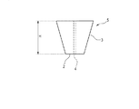
図1は、方光体突起5(突起5)を有する静電紡糸用スピナレットの斜視図である。 FIG. 1 is a perspective view of an electrospinning spinneret having a rectangular projection 5 (projection 5).
本実施形態の静電紡糸用スピナレット1は、導電性金属材料で構成された構造体である。該構造体は、X方向(長軸方向ともいう。)と、Y方向(厚み方向ともいう。)と、Z方向(短軸方向ともいう。)で形成される本体部20で構成される。
該構造体において、その厚み方向(Y方向)を構成する前記金属材料の一部が短軸方向(Z方向)に沿って突起5を形成するように延びている。言い換えると、構造体の本体部20の第一の面(一面)22と対向する逆側の第二の面(他の一面)21(本体部20の一側面を構成する)において、複数の突起5が短軸方向(Z方向)に沿って伸びるように形成されている。ここで本体部20は、静電紡糸用スピナレット1を構成する構造体から突起5を除いた部分を意味する。
The
In the structure, a part of the metal material forming the thickness direction (Y direction) extends along the minor axis direction (Z direction) so as to form the
当該突起5は、頂部(突起頂部)2と側面部3とを有し、各頂部2に原料流体を吐出する吐出孔4が1孔ずつ設けられている。静電紡糸用スピナレット1を高電圧で帯電させることで、吐出孔4付近に原料流体からなるテイラーコーン7を形成し、テイラーコーン7の先端からナノファイバ8を紡出する。
The
本実施形態の静電紡糸用スピナレット1は、吐出孔4が設けられた突起5を有するため、高電圧で帯電した静電紡糸用スピナレット1の突起5に電荷が集中し、突起5の周辺に強力な電界が発生する。この強力な電界によって、テイラーコーン7に与えられる捕集電極表面へと向かう力が増大し、テイラーコーン7の拡大および隣接するテイラーコーン同士の接触を抑制する。また、静電紡糸用スピナレット1は、突起5と谷部6が長軸方向(X方向)に沿って交互に配される構成を有するため、テイラーコーン7は側面部3と谷部6に沿って、隣接する突起5まで拡大しにくく、隣接するテイラーコーン7同士の接触が抑制される。
Since the
静電紡糸用スピナレット1は、導電性の金属材料で構成されていればよく、鉄、アルミニウム、ステンレス剛、真鍮など任意の導電性の金属材料で構わない。また、これら複数の金属材料の組み合わせや合金から構成されていてもよい。
The
静電紡糸用スピナレット1の長軸方向、厚み方向、および短軸方向の各長さは、任意に選択することができる。例えば、スピナレットの長軸方向は1500mm以下、スピナレットの厚み方向は100mm以下、スピナレットの短軸方向は150mm以下の範囲が挙げられる。静電紡糸用スピナレット1の寸法を前記長さの範囲内にすることにより、静電紡糸装置へのスピナレットの着脱作業や紡糸後のスピナレットのメンテナンス作業を容易に行うことができる。
The lengths in the long axis direction, the thickness direction, and the short axis direction of the
本明細書では、上記の通り、長軸方向、単軸方向と言い分けてはいるが、スピナレットの幅方向と高さ方向の長さが互いに同じものも、本発明から排除するものではない。また、本明細書では、「Z方向を、「短軸方向」と言い、スピナレットの高さ方向を示す」、と説明し、突起5がスピナレットの下面に突出した構造のもののみ図示したが、これらスピナレットは、突起5が構造体の一側面から捕集電極表面に向いていればよく、突起5が地面に向かって突出する向きで使用されてもよいし、突起5が地面に対して水平方向や上向きになるように使用されてもよい。
In the present specification, as described above, the long-axis direction and the single-axis direction are separately referred to, but the spinneret having the same length in the width direction and the height direction is not excluded from the present invention. Further, in the present specification, it is described that "the Z direction is referred to as "minor axis direction" and indicates the height direction of the spinneret", and only the structure in which the
本実施形態の静電紡糸用スピナレット1が有する突起5の数は特に限定されるものではないが、1000個以下が好ましい。突起5の数を1000個以下にすることにより、テイラーコーン7や紡出されて帯電したナノファイバ8同士での静電反発が発生しにくく、ナノファイバ8の紡出が均一となる。
The number of the
図2は、隣り合う突起同士で突起5の頂部2の高さが異なる静電紡糸用スピナレット1の斜視図である。本実施形態の静電紡糸用スピナレット1は、トッププレート30と、ノズル51の二つの部品を接合することにより得られる。リード孔16は、原料流体を吐出孔に導くために吐出孔と対で設けられ、一般的にスピナレット製作上、機能上の理由から大きい孔径を有している。
FIG. 2 is a perspective view of the
図3は、本静電紡糸用スピナレットが有する方光体突起5(突起5)の断面図である。図3は特に図1の静電紡糸用スピナレットの突起5を拡大したものを示し、左右に線対称な形状を有する。図2の静電紡糸用スピナレットの突起5は左右に線対称でない点を除いて、図3に示したものと同様な構成を有する。
FIG. 3 is a cross-sectional view of the projections 5 (projections 5) of the present electrospinning spinneret. FIG. 3 particularly shows an
本発明において静電紡糸用スピナレット1が有する突起5における、突起5の高さH(H方向の長さ)は特に限定されるものではないが、0.1mm以上であることが好ましい。電荷は尖った箇所に集中しやすいため、突起5の先端に電荷が集中しやすい。その結果、突起5周辺に発生する電界は、同じ印加電圧であっても、突起5のないスピナレットと比べて、より強力な電界となり、テイラーコーン7の挙動は安定する。突起5の高さを0.1mm以上にすることにより、突起5の周辺に強力な電界を発生させ、テイラーコーン7が捕集電極表面へ引き寄せられる力を強めることができる。突起5の高さはより好ましくは、1mm以上である。
In the present invention, the height H (length in the H direction) of the
本実施形態の静電紡糸用スピナレット1が有する突起5の配し方は特に限定されるものではなく、静電紡糸用スピナレット1の形状や大きさによって、一次元的に配してもよいし、捕集電極表面に対して平行になるように、二次元的に配しても構わない。突起5を一次元的に配する場合、図1に例示するように隣接する突起5同士で高さが同じになるように配してもよいし、図2に例示するように隣接する突起5同士で高さが異なるように配しても構わない。この例示のように、ノズル51の長軸方向の中心から左右対称とし、ノズル51の長軸方向の中心から離れて配される突起5であるほど突起5の頂部2の高さ(第一の面22から頂部2までの距離)が低くなるように配することで、各々の突起5に均一な電界を発生させ、均質なナノファイバ8を得ることができるため、好ましい。なお、隣り合う突起同士の頂部の高さが同じ場合が含まれていてもよい。
The method of arranging the
本静電紡糸用スピナレットが有する突起5の頂部2となる面の面方向は特に限定されるものではないが、全ての突起5の頂部2となる面が同一の面方向を向いていることが好ましい。
The surface direction of the
本実施形態の静電紡糸用スピナレット1の突起5の形状は特に限定されるものではないが、テイラーコーン7の安定性や、スピナレットの加工のしやすさや加工費などを考慮すると方光体の形状であることが好ましい。また、突起5は、方光体の形状に限定して解釈されるものではなく、多面体、半球、錐体、多角柱、かまぼこ形などその要旨を逸脱しない範囲内において、種々の実施形態を適用することができる。複数の突起5は略同一形状を有するのが好ましい。
The shape of the
本発明の静電紡糸用スピナレットを用いて静電紡糸をする場合、突起を捕集面に対して垂直方向になるようにスピナレットを設置し、垂直方向に原料流体を紡出し、ナノファイバを捕集することができるだけでなく、突起を捕集面に対して水平方向になるようにスピナレットを設置し、水平方向に原料流体を紡出し、ナノファイバを捕集することができる。 When performing electrospinning using the electrospinning spinneret of the present invention, the spinneret is installed so that the projections are perpendicular to the collecting surface, and the raw material fluid is spun out in the perpendicular direction to capture the nanofibers. Not only the nanofibers can be collected, but the spinneret is installed so that the protrusions are horizontal to the collection surface, and the raw material fluid is spun out in the horizontal direction to collect the nanofibers.
本実施形態の静電紡糸用スピナレット1が有する吐出孔4の形状は、特に限定されるものではなく、円形、多角形、星型、Y型、C型などのいずれも選択できるが、スピナレットの加工の容易性を考慮すると円形がより好ましい。また、複数の吐出孔4は略同一形状を有することが好ましい。
The shape of the
また、図1、2に示す各吐出孔4の隣り合う吐出孔間の距離であるピッチPは、1mmを越えるように設定され、このようなピッチPを確保するように複数の突起5は、構造体の長軸方向(X方向)に沿って並ぶように形成される。1mmを越えるピッチPを確保することにより、隣接する吐出孔4から吐出される原料流体のテイラーコーン7の接触が抑制される。
Further, the pitch P, which is the distance between the adjacent ejection holes of the ejection holes 4 shown in FIGS. 1 and 2, is set to exceed 1 mm, and the plurality of
本実施形態の静電紡糸用スピナレット1が有する突起5における頂部2の面積(吐出孔を含む面積)は特に限定されるものではないが、0.1〜100mm2の範囲であることが好ましい。頂部2の面積を0.1mm2以上にすることにより、テイラーコーン7を確実に保持し、テイラーコーン7の周囲への拡大および隣接するテイラーコーン7同士の接触を抑制することができる。頂部2の面積を100mm2以下にすることにより、ピッチPを小さくでき、十分なナノファイバ8の生産性を維持することができる。より好ましい頂部2の面積は、1〜50mm2の範囲である。
The area of the top portion 2 (area including the discharge hole) of the
本実施形態の吐出孔4の孔径は限定されるものではないが、0.1mm〜1.0mmとすることが好ましい。吐出孔4の孔径を0.1mm以上にすることにより、静電紡糸用スピナレットの洗浄性が向上するため好ましい。また、吐出孔4の孔径を1.0mm以下にすることにより、低粘度の原料流体や低吐出量の場合において、テイラーコーン7が安定な挙動を示し、ナノファイバ8の紡出が均一となるため好ましい。
Although the diameter of the
本実施形態の静電紡糸用スピナレット1が有する頂部2に配される吐出孔4の位置は、特に限定されるものではなく、頂部2に配されていればよく、頂部2の面の中心や外周などが例示できるが、頂部2の中心に配されることが好ましい。吐出孔4を中心として、頂部2の面に沿ってテイラーコーン7が形成されるため、テイラーコーン7が安定な挙動を示し、均一なナノファイバ8を得ることができる。
The position of the
図4は、内部に原料流体を溜めるための内部空間を有する静電紡糸用スピナレットの断面図である。図4に示すように、本実施形態の静電紡糸用スピナレット1は、トッププレート30と、ノズル40の二つの部品を接合することにより得られる。しかしながら、静電紡糸用スピナレット1を構成する部品はこのような形態には限定されない。
FIG. 4 is a sectional view of an electrospinning spinneret having an internal space for accumulating a raw material fluid therein. As shown in FIG. 4, the
本実施形態の静電紡糸用スピナレット1は、第一の面22に設けられた流入口10より紡糸用の原料流体が供給される。流入口10より供給された原料流体は、スピナレット内部の内部空間9に溜められ、内部空間9の底面に穿孔されるとともに突起5内を貫通する吐出孔4より吐出される。高粘度の原料流体を用いる場合、内部空間9がバッファとして機能するため、各々の吐出孔から均一に原料流体が吐出される。また、スピナレット構造が単純なため、紡糸後の洗浄工程やメンテナンスを容易に行うことができる。
In the
本実施形態の静電紡糸用スピナレット1への原料流体の供給方法は、特に限定されるものではないが、ギアポンプ、シリンジポンプ、溶液への加圧による供給などが例示できる。ギアポンプは、分解洗浄に時間を要するなどメンテナンス性に難があるが、連続的に原料流体を供給できる利点がある。また、シリンジポンプはバッチ式であり、一度に原料流体を供給可能な量に限りがあるが、ギアポンプよりも広い範囲の粘度の原料流体を供給することが可能である。使用する原料流体や生産量、メンテナンス性に応じて、適宜選択することができる。
The method of supplying the raw material fluid to the
図5は、内部に原料流体を溜めるための内部空間を有する静電紡糸用スピナレットの内部空間を可視化した斜視図である。 FIG. 5 is a perspective view in which an internal space of an electrospinning spinneret having an internal space for accumulating a raw material fluid is visualized.
本実施形態の静電紡糸用スピナレット1に有する内部空間9の体積と、吐出孔4の面積と長さは、内部空間9のスピナレットの長軸方向に対して垂直方向の断面積をA、内部空間9のスピナレットの長軸方向の長さをB、吐出孔4の断面積をa、吐出孔4の長さ(内部空間9から吐出孔の出口までのノズルを貫通する長さ)をb、1つの内部空間9の底面に穿孔された吐出孔4の数をnとした場合、下記の式(1)の関係を満たすことが好ましい。該式(1)を満たす範囲にすることにより、原料流体を各々の吐出孔4に供給する際、吐出孔4の長さ方向への原料流体の流動性が、内部空間9の長軸方向への原料流体の流動性を上回り、静電紡糸用スピナレット1内部の背圧が上がり、各々の吐出孔4に均一に原料流体が供給されやすく、ナノファイバ8の紡出が均一となりやすい。
The volume of the

図6は、内部に原料流体の流路を有する静電紡糸用スピナレットおよびその構成部品の断面図の一例である。 FIG. 6 is an example of a cross-sectional view of an electrospinning spinneret having a flow path for a raw material fluid and its components.
本実施形態の静電紡糸用スピナレット1は、原料流体を流入口10より複数の吐出孔4へ供給することができる。流入口10から各々の吐出孔4へ分配するために、内部に内部空間9を有していてもよいが、流体を分配するために分岐した複数の流路11を有していることが好ましい。極めて低粘度の原料流体を、内部空間9を有するスピナレットに流入させると、内部空間9に原料流体を充填する過程で原料流体の方が空気よりも比重が大きいため、内部空間9に空気を抱き込みながら充填され、原料流体を各々の吐出孔4に均一に供給することが困難である。また、内部空間9に空気を抱き込むことなく原料流体を充填させたとしても、流入口10から各々の吐出孔までの距離が異なり、各々の吐出孔4へ原料流体を均一に供給することが困難である。
静電紡糸用スピナレット1の内部に流路11を形成することで、空気と原料流体の比重の差の影響を受けにくくすることができる。これにより、スピナレット内部に空気を抱き込むことなく原料流体を内部空間9に充填することができ、さらに流入口から各々の吐出孔までの距離が略等距離であることから、原料流体を各々の吐出孔4に均一に供給することができ、均一なナノファイバ8を得ることができる。
The
By forming the
本実施形態の流入口10から各々の吐出孔4までの距離の差、すなわち、各流路11の距離の差は各々の吐出孔4に原料流体を均一に供給することができるという点で、10%以内であることが好ましい。流入口10から各々の吐出孔4までの距離の差を10%以内にすることにより、各々の吐出孔4にかかる背圧の差が小さく、各々の吐出孔4からの原料流体の吐出量の差がナノファイバ8に与える影響を抑制することができる。
The difference in the distance from the
本実施形態の流路11の形状は、特に限定されないが、流路11の形状と原料流体の流れの関係を解析した結果、効率よく各々の吐出孔4に原料流体を均一に供給することができるという点で、図6に例示するような枝分かれ図の形状であることが好ましい。また、図6の下半分に示すように、本実施形態の静電紡糸用スピナレット1は、トッププレート30、ノズル40に加え、二枚の分配板12、15の合計四つの部品を接合することにより得られる。各部品の内部および接合面には流路11が形成されており、容易に流路11を形成することができる。
The shape of the
図7は、静電紡糸用スピナレット1の内部に原料流体の流路を有するための分配板12、15の斜視図である。
FIG. 7 is a perspective view of the
本実施形態の静電紡糸用スピナレット1では、内部に流路11を形成するために、図6、図7に例示するような取り外し可能な分配板12、15が設置される。分配板12は、表面(接合面)を掘削されて形成される溝13と、当該溝に分配板12の厚み方向を貫通する孔14を有しており、製作とスピナレット洗浄が容易になるために用いられる。分配板12の設置によって流路11を形成させることができ、紡糸後にノズル40と分配板12、15とに分解することで、スピナレットの洗浄工程を簡便かつ効果的に行うことができる。また、分配板12の溝およびの孔の形状が異なる分配板(たとえば分配板15)を複数作製しておくことで、随時、原料流体の粘度に適した分配板12に取り替えることができ、更に幅広い粘度の原料流体に対応することができる。
In the
分配板の溝の体積と、溝を貫通する孔の面積および長さは、原料流体が流れる方向に対して垂直方向の分配板の溝13の断面積をD、分配板の溝を貫通する孔14の面積をdとした場合、流路11の形状と原料流体の流れの関係を解析した結果、効率よく各々の吐出孔4に原料流体を均一に供給することができるという点で、Dは0.1〜5mm2、dは0.1〜1mm2の範囲にすることが好ましい。前記範囲を満たすと、粘度10〜5000cPの原料流体を分配する際、低粘度の原料流体の場合は空気を抱きこむことなく、高粘度の原料流体は背圧が上がりすぎることもなく、各々の吐出孔4に均一に原料流体が供給されやすく、ナノファイバ8の紡出が均一となりやすい。
The volume of the groove of the distribution plate and the area and length of the hole penetrating the groove are defined by the sectional area D of the
分配板15は、表面を掘削されて形成される二つの溝13a、13bを有する。溝13aに分配板15の厚み方向を貫通する孔14a、14bが設けられ、溝13bに孔14c、14dが設けられる。分配板15の溝13a、13b各々においても、分配板12におけるD、L、d、lと同様の前記の理由から前記範囲を満たすことが好ましい。
The
図8は、流路を有したトッププレート31を使用した静電紡糸用スピナレット1の斜視図である。本実施形態の静電紡糸用スピナレット1は、トッププレート30と、ノズル52の二つの部品を接合することにより得られる。
FIG. 8 is a perspective view of the
本実施形態の静電紡糸用スピナレット1の内部に流路11を形成するために、図8に例示するような流路を有するトッププレート31を使用してもよい。流路11を有するトッププレート31を使用した場合、分配板を使用した場合よりも部品数を少なくすることができ、紡糸後の洗浄工程やメンテナンスを容易に行うことができる。
In order to form the
本実施形態の静電紡糸用スピナレット1を用いて静電紡糸をする際、原料流体に含まれる材料は特に限定されるものではなく、適宜選択することができる。この様な材料としては、ポリエステル、ナイロン、ポリウレタン、ポリフッ化ビニリデン、ポリアクリロニトリル、ポリイミド、ポリアミド、ポリスルフォン、ポリエーテルスルフォン、ポリビニルアルコール、ポリスチレン、ポリメタクリル酸メチルなどの高分子材料の他、アルミナや酸化チタンなどの無機材料などを例示できる。ナノファイバ化した際に発現する効果を考慮し、適宜選択することができる。また、これらポリマーは、単独で使用してもよく、2種類以上のポリマーを混合して使用してもよい。更には、これらポリマーは他の機能性材料と複合されていてもよく、そのような機能性材料としては、難燃剤、消臭剤、酸化防止剤、帯電防止剤、顔料などの機能付与材の他、金ナノ粒子や二酸化チタンナノ粒子、ハイドロキシアパタイトナノ粒子、カーボンナノチューブやグラフィンなどのナノ材料を例示できる。
When electrostatic spinning is performed using the
本実施形態の静電紡糸用スピナレット1を用いて静電紡糸をする際、原料流体に含まれる溶媒は特に限定されるものではなく、ポリマーを室温もしくは加熱下で溶解可能な溶媒を、適宜選択することができる。この様な溶媒としては、N,N−ジメチルホルムアミド、N,N−ジメチルアセトアミド、N−メチル−2−ピロリドン、テトラヒドロフラン、テトラメチルユリア、トリメチルフォスフェート、1,1,1,3,3,3−ヘキサフルオロ−2−プロパノール、ヘキサフルオロ酢酸、メチルエチルケトン、ジメチルスルホキシド、アセトン、ブチルアセテート、シクロヘキサン、ブチロラクトン、テトラエチルユリア、イソホロン、トリエチルフォスフェート、カルビトールアセテート、プロピレンカーボネートなどが例示でき、溶媒のポリマーに対する溶解性や揮発性、誘電率、粘度、表面張力などを考慮して、適宜選択することができる。また、これら溶媒は、単独で使用してもよく、2種類以上の溶媒を混合して使用してもよい。2種類以上の溶媒を混合して使用する場合には、揮発性の高い溶媒と揮発性の低い溶媒を混合することで、電界紡糸過程におけるポリマー溶液の揮発性を制御することができるので、より好ましい。この様な組み合わせとしては、N,N−ジメチルホルムアミドとアセトン、N,N−ジメチルアセトアミドとアセトン、N−メチル−2−ピロリドンとアセトンなどを例示することができる。2種類以上の溶媒を混合して使用する場合の混合比率は、特に限定されるものではなく、求めるポリマー溶液の物性、例えば濃度や粘度、揮発性、導電性、表面張力などを考慮して、適宜調整することができる。これによって、得られるナノファイバ8の繊維径や繊維形態を容易に制御可能となったり、また静電紡糸時の溶液吐出量の調整が容易となり、例えば吐出量を増大させてナノファイバ8の生産性を向上させることができたりする。
When performing electrospinning using the
本実施形態の静電紡糸用スピナレット1を用いて静電紡糸をする際、原料流体の特性を調整する目的で、添加剤を添加することができる。添加剤の種類は特に限定されるものではなく、有機もしくは無機の塩などを、適宜選択することができる。例えば、イオン性の界面活性剤を添加した場合には、原料流体の表面張力が低下し、また電気伝導率が向上するので、イオン性の界面活性剤が添加されていない原料流体を静電紡糸した場合に比べて、球状粒子(ビーズ)の発現が少なく、平均繊維径が小さいナノファイバ8が得られるので好ましい。添加剤の添加量についても特に限定されるものではなく、求める原料流体の特性調整効果に応じて適宜選択することができるが、好ましい範囲としては、原料流体中に0.005〜0.5質量%、更に好ましい範囲としては、原料流体中に0.01〜0.3質量%を例示できる。
When performing electrospinning using the
本実施形態の静電紡糸用スピナレット1を用いて静電紡糸をする際、原料流体のポリマー濃度は特に限定されるものではなく、原料流体の粘度、そして静電紡糸して得られるナノファイバ8の平均繊維径や繊維形態、そして生産性などを考慮して、適宜調整することができるが、好ましい濃度範囲としては3〜30質量%、より好ましい範囲としては4〜25質量%を例示することができる。ポリマーの濃度が3質量%以上であれば、ビーズ構造があまり見られない、十分に小さい平均繊維径のナノファイバ8が、満足できる生産性で得られるので好ましく、4質量%以上であれば、ビーズ構造がほぼ見られない、満足できる平均繊維径のナノファイバ8が、十分な生産性で得られるのでより好ましい。また、ポリマーの濃度が30質量%以下であれば、静電紡糸に適した粘度となり、安定した紡糸性でナノファイバ8が得られるので好ましく、25質量%以下であれば、さらに安定した紡糸性となるのでより好ましい。
When electrospinning is performed using the
本実施形態の静電紡糸用スピナレット1を用いて静電紡糸をする際、原料流体の粘度は特に限定されるものではなく、10〜5000cPの範囲であることが好ましく、30〜3000cPの範囲であることがより好ましい。原料流体の粘度を10cP以上にすることにより、曳糸性がよく、ビーズが発現しにくい。原料流体の粘度を5000cP以下にすることにより、粘性が低いため、原料流体を静電紡糸用スピナレット1の各々の吐出孔4まで供給することが容易である。本実施形態の静電紡糸用スピナレット1は、突起5に吐出孔4を有する構成であるために、突起5周辺に発生する強力な電界によって、テイラーコーン7は安定な挙動を示し、特に、粘度が10〜200cPであるような低粘度の原料流体を用いて、均一で細い繊維径のナノファイバ8を製造することができる。
When performing electrospinning using the
以下、実施例によって本発明を詳細に説明するが、本発明は、下記実施形態に限定して解釈されるものではなく、その要旨を逸脱しない範囲内において種々の実施形態に適用することができる。なお、実施例中に示したナノファイバの平均繊維径の測定方法を以下に示す。 Hereinafter, the present invention will be described in detail with reference to Examples, but the present invention is not construed as being limited to the following embodiments and can be applied to various embodiments without departing from the gist thereof. .. The method for measuring the average fiber diameter of the nanofibers shown in the examples is shown below.
(原料流体の粘度)
気温25℃および湿度30%の条件でBROOKFIELD社製の粘度計RVDV−IPrimeと、コーンスピンドルCPE−41を使用して、後述する原料流体の粘度を測定した。
(Viscosity of raw material fluid)
The viscosity of the raw material fluid described below was measured using a viscometer RVDV-I Prime manufactured by BROOKFIELD and a cone spindle CPE-41 under the conditions of an air temperature of 25° C. and a humidity of 30%.
(平均繊維径)
株式会社日立ハイテクノロジーズ製の走査型電子顕微鏡SU8020を使用して、ナノファイバを観察し、画像解析ソフトを用いてナノファイバ50ヶ所の直径を測定した。ナノファイバ50ヶ所の繊維径の平均値を平均繊維径とした。
(Average fiber diameter)
Nanofibers were observed using a scanning electron microscope SU8020 manufactured by Hitachi High-Technologies Corporation, and the diameters of 50 nanofibers were measured using image analysis software. The average value of the fiber diameters at 50 nanofibers was defined as the average fiber diameter.
(紡糸安定性)
静電紡糸を開始して、隣接するテイラーコーン同士が接触することなく2時間以上経過し、テイラーコーンからのナノファイバの紡出が連続的であった場合を「◎」、隣接するテイラーコーン同士が接触することなく2時間以上経過したが、テイラーコーンからのナノファイバの紡出が断続的であった場合を「○」、隣接するテイラーコーン同士が接触するまでに要した時間が10分〜2時間の範囲であり、テイラーコーンからのナノファイバの紡出が連続的または断続的であった場合を「△」、隣接するテイラーコーン同士が接触するまでに要した時間が10分以下であり、テイラーコーンからのナノファイバの紡出が連続的または断続的であった場合を「×」として紡糸安定性を評価した。
(Spinning stability)
"◎" indicates that nanofibers were continuously spun from the Taylor cones for two hours or more after the electrostatic spinning was started and the adjacent Taylor cones were not in contact with each other, and the adjacent Taylor cones were adjacent to each other. When more than 2 hours have passed without touching each other, but the spinning of the nanofibers from the Taylor cone was intermittent, "○" indicates that the time required for the adjacent Taylor cones to come into contact with each other was 10 minutes ~ It is a range of 2 hours, "△" when the spinning of nanofibers from the Taylor cone was continuous or intermittent, and the time required for contacting adjacent Taylor cones was 10 minutes or less. The spinning stability was evaluated as "x" when the spinning of nanofibers from the Taylor cone was continuous or intermittent.
<実施例1>
Solvay製のポリフッ化ビニリデン−ヘキサフルオロプロピレン(PVDF−HFP)樹脂であるSolef 21216を、N,N−ジメチルホルムアミドに8質量%の濃度で溶解し、添加剤としてラウリル硫酸ナトリウムを0.1質量%となるように添加し、原料流体を調製した。この原料流体の粘度は461cPであった。次に、捕集電極の上に置いたアルミシートを基材として、この上に前記原料流体を、図1に記載の突起を有する静電紡糸用スピナレットを用いて、静電紡糸をして、PVDF−HFPナノファイバを作製した。なお、スピナレットの長さは100mm、スピナレットの厚さは20mm、スピナレットの高さは40mm、突起の高さは1.5mm、突起の形状は方光体、突起は一次元的に配され、吐出孔出口の形状は円形、吐出孔の出口の孔径は0.3mm、頂部の面積(吐出孔出口の面積を含む)は1mm2、1つの突起につき1つの吐出孔を配し、スピナレットは4個の突起を有し、隣り合う吐出孔間の距離は8mm、流入口の孔径は2mmであった。本実施例の静電紡糸用スピナレットは、その内部に、原料流体を流入口から各々の吐出孔へ分配するため、図4に例示するような内部空間を形成している。内部空間の長さは80mm、内部空間の厚さは10mm、内部空間の高さは35mm、吐出孔の長さは5mmであった。本実施例の紡糸条件は、1個の吐出孔(単孔)への原料流体の供給量は1.0mL/hr、印加電圧は45kV、紡糸距離は150mm、紡糸空間は気温25度Cおよび湿度30%であった。本実施例では、原料流体の粘度が高いため、隣接するテイラーコーン同士が接触することなく2時間以上に亘って安定的な紡糸が可能であったため、十分な操業性であった。また、テイラーコーンからのナノファイバの紡出が連続的であったため、十分な品質のPVDF−HFPナノファイバを得られた。得られたPVDF−HFPナノファイバの平均繊維径は、78±15nmであった。
<Example 1>
Solef 21216, which is polyvinylidene fluoride-hexafluoropropylene (PVDF-HFP) resin manufactured by Solvay, is dissolved in N,N-dimethylformamide at a concentration of 8% by mass, and sodium lauryl sulfate as an additive is added at 0.1% by mass. Was added to prepare a raw material fluid. The viscosity of this raw material fluid was 461 cP. Next, using an aluminum sheet placed on the collecting electrode as a base material, the raw material fluid thereon is subjected to electrostatic spinning using the spinneret for electrostatic spinning having the protrusions shown in FIG. PVDF-HFP nanofibers were prepared. The length of the spinneret is 100 mm, the thickness of the spinneret is 20 mm, the height of the spinneret is 40 mm, the height of the protrusion is 1.5 mm, the shape of the protrusion is a prism, and the protrusion is arranged one-dimensionally. The shape of the hole outlet is circular, the hole diameter of the outlet of the discharge hole is 0.3 mm, the area of the top part (including the area of the outlet of the discharge hole) is 1 mm 2 , one discharge hole is arranged for each protrusion, and four spinnerets are provided. The distance between adjacent ejection holes was 8 mm, and the hole diameter of the inflow port was 2 mm. The electrospinning spinneret of the present embodiment has an internal space as illustrated in FIG. 4 for distributing the raw material fluid from the inflow port to each discharge hole. The internal space had a length of 80 mm, the internal space had a thickness of 10 mm, the internal space had a height of 35 mm, and the ejection holes had a length of 5 mm. The spinning conditions of this example were as follows: the feed rate of the raw material fluid to one discharge hole (single hole) was 1.0 mL/hr, the applied voltage was 45 kV, the spinning distance was 150 mm, the spinning space had an air temperature of 25° C. and humidity. It was 30%. In this example, since the raw material fluid had a high viscosity, the adjacent spinning cones could be stably spun for 2 hours or more without coming into contact with each other, resulting in sufficient operability. Moreover, since the spinning of nanofibers from the Taylor cone was continuous, PVDF-HFP nanofibers of sufficient quality were obtained. The average fiber diameter of the obtained PVDF-HFP nanofibers was 78±15 nm.
<実施例2>
Solvay製のPVDF−HFP樹脂であるSolef 21216を、N,N−ジメチルホルムアミドに6質量%の濃度で溶解し、添加剤としてラウリル硫酸ナトリウムを0.1質量%となるように添加し、原料流体を調製した。この原料流体の粘度は162cPであった。次に、アルミシートを基材として、この上に前記原料流体を、実施例1と同様の静電紡糸用スピナレットを用いて、実施例1と同様の紡糸条件で静電紡糸をして、PVDF−HFPナノファイバを作製した。本実施例では、原料流体の粘度が低いが、方光体の突起の周辺に強力な電界を発生させ、テイラーコーンが捕集電極表面へ引き寄せられる力を強めることができたため、隣接するテイラーコーン同士が接触することなく2時間以上に亘って安定的な紡糸が可能で十分な操業性であった。しかし、スピナレットの内部に原料流体を分配する流路を有しておらず、テイラーコーンからのナノファイバの紡出が断続的であったため、十分な品質のPVDF−HFPナノファイバを得られなかった。得られたPVDF−HFPナノファイバの平均繊維径は、62±25nmであった。
<Example 2>
PVDF-HFP resin Solef 21216 manufactured by Solvay was dissolved in N,N-dimethylformamide at a concentration of 6% by mass, and sodium lauryl sulfate was added as an additive to 0.1% by mass, and a raw material fluid was added. Was prepared. The viscosity of this raw material fluid was 162 cP. Next, using an aluminum sheet as a base material, the above raw material fluid was subjected to electrostatic spinning under the same spinning conditions as in Example 1 using the same spinneret for electrostatic spinning as in Example 1, and PVDF was used. -HFP nanofiber was produced. In this example, although the viscosity of the raw material fluid was low, a strong electric field was generated around the projections of the direction body, and the force of attracting the Taylor cone to the surface of the collecting electrode was strengthened. Stable spinning was possible for 2 hours or more without mutual contact, and the workability was sufficient. However, since the spinneret does not have a flow passage for distributing the raw material fluid and the spinning of nanofibers from the Taylor cone was intermittent, PVDF-HFP nanofibers of sufficient quality could not be obtained. . The average fiber diameter of the obtained PVDF-HFP nanofibers was 62±25 nm.
<実施例3>
原料流体は実施例2と同様の条件で調製した。次に、捕集電極の上に置いたアルミシートを基材として、この上に前記原料流体を、図1に記載の突起を有する静電紡糸用スピナレットを用いて、静電紡糸をして、PVDF−HFPナノファイバを作製した。スピナレットの長さは100mm、スピナレットの厚さは20mm、スピナレットの高さは40mm、突起の高さは1.5mm、突起の形状は方光体、突起は一次元的に配され、吐出孔出口の形状は円形、吐出孔の出口の孔径は0.3mm、頂部の面積(吐出孔出口の面積を含む)は1mm2、1つの突起につき1つの吐出孔を配し、スピナレットは4個の突起を有し、隣り合う吐出孔間の距離は8mm、流入口の孔径は2mmであった。本実施例の静電紡糸用スピナレットは、その内部に、原料流体を流入口から各々の吐出孔へ分配するため、図6に例示するようなトーナメント状の流路を、図7の斜視図に例示するような分配板を用いて形成した。原料流体が流れる方向に対して垂直方向の分配板の溝の断面積は2mm2、原料流体が流れる方向の溝の長さは35mm、分配板の溝を貫通する孔の面積は0.5mm2、分配板の溝を貫通する孔の長さは3mmであった。本実施例の紡糸条件は、実施例1と同様の紡糸条件であった。本実施例では、原料流体の粘度が低いが、方光体の突起の周辺に強力な電界を発生させ、テイラーコーンが捕集電極表面へ引き寄せられる力を強めることができたため、隣接するテイラーコーン同士が接触することなく2時間以上に亘って安定的な紡糸が可能で十分な操業性であった。また、スピナレットの内部に原料流体を分配する流路を有しており、テイラーコーンからのナノファイバの紡出が連続的であったため、十分な品質のPVDF−HFPナノファイバを得られた。得られたPVDF−HFPナノファイバの平均繊維径は、64±13nmであった。
<Example 3>
The raw material fluid was prepared under the same conditions as in Example 2. Next, using an aluminum sheet placed on the collecting electrode as a base material, the raw material fluid thereon is subjected to electrostatic spinning using the spinneret for electrostatic spinning having the protrusions shown in FIG. PVDF-HFP nanofibers were prepared. The length of the spinneret is 100 mm, the thickness of the spinneret is 20 mm, the height of the spinneret is 40 mm, the height of the protrusion is 1.5 mm, the shape of the protrusion is a prism, and the protrusion is one-dimensionally arranged. Has a circular shape, the diameter of the outlet of the discharge hole is 0.3 mm, the area of the top (including the area of the outlet of the discharge hole) is 1 mm 2 , one discharge hole is arranged for each protrusion, and the spinneret has four protrusions. The distance between adjacent discharge holes was 8 mm, and the hole diameter of the inflow port was 2 mm. The electrospinning spinneret of the present embodiment has a tournament-shaped flow path as illustrated in FIG. 6 in the perspective view of FIG. 7 in order to distribute the raw material fluid from the inflow port to each discharge hole. It was formed using a distribution plate as illustrated. The cross-sectional area of the groove of the distribution plate in the direction perpendicular to the direction of the flow of the raw material fluid is 2 mm 2 , the length of the groove in the direction of the flow of the raw material fluid is 35 mm, and the area of the hole penetrating the groove of the distribution plate is 0.5 mm 2. The length of the hole penetrating the groove of the distribution plate was 3 mm. The spinning conditions of this example were the same as those of Example 1. In this example, although the viscosity of the raw material fluid was low, a strong electric field was generated around the projections of the prism, and the force of attracting the Taylor cone to the surface of the collecting electrode was strengthened. Stable spinning was possible for 2 hours or more without mutual contact, and the workability was sufficient. In addition, since the spinneret has a channel for distributing the raw material fluid and the nanofibers were continuously spun from the Taylor cone, PVDF-HFP nanofibers of sufficient quality were obtained. The average fiber diameter of the obtained PVDF-HFP nanofibers was 64±13 nm.
<実施例4>
原料流体は実施例2と同様の条件で調製した。この原料流体の粘度は162cPであった。次に、捕集電極の上に置いたアルミシートを基材として、この上に前記原料流体を、図9に記載の突起を有する静電紡糸用スピナレットを用いて、静電紡糸をして、PVDF−HFPナノファイバを作製した。なお、スピナレットの長さは100mm、スピナレットの厚さは20mm、スピナレットの高さは40mm、突起の高さは1.5mm、突起の形状は四角錘、突起は一次元的に配され、吐出孔出口の形状は円形、吐出孔の出口の孔径は0.3mm、頂部の面積(吐出孔出口の面積を含む)は1mm2、1つの突起につき1つの吐出孔を配し、スピナレットは4個の突起を有し、隣り合う吐出孔間の距離は8mm、流入口の孔径は2mmであった。本実施例の静電紡糸用スピナレットは、その内部に、原料流体を流入口から各々の吐出孔へ分配するため、図4に例示するような内部空間を形成している。内部空間の長さは80mm、内部空間の厚さは10mm、内部空間の高さは35mm、吐出孔の長さは5mmであった。本実施例の紡糸条件は、本実施例1と同様の紡糸条件であった。本実施例では、原料流体の粘度が低いが、方光体の突起の周辺に強力な電界を発生させ、テイラーコーンが捕集電極表面へ引き寄せられる力を強めることができたため、隣接するテイラーコーン同士が接触することなく2時間以上に亘って安定的な紡糸が可能で十分な操業性であった。しかし、スピナレットの内部に原料流体を分配する流路を有しておらず、テイラーコーンからのナノファイバの紡出が断続的であったため、十分な品質のPVDF−HFPナノファイバを得られなかった。得られたPVDF−HFPナノファイバの平均繊維径は、58±26nmであった。
<Example 4>
The raw material fluid was prepared under the same conditions as in Example 2. The viscosity of this raw material fluid was 162 cP. Next, using an aluminum sheet placed on the collecting electrode as a base material, the raw material fluid thereon is subjected to electrostatic spinning using an electrospinning spinneret having protrusions shown in FIG. PVDF-HFP nanofibers were prepared. The length of the spinneret is 100 mm, the thickness of the spinneret is 20 mm, the height of the spinneret is 40 mm, the height of the protrusion is 1.5 mm, the shape of the protrusion is a square pyramid, and the protrusion is arranged one-dimensionally. The shape of the outlet is circular, the diameter of the outlet of the outlet is 0.3 mm, the area of the top (including the area of the outlet of the outlet) is 1 mm 2 , one outlet is arranged for each protrusion, and four spinnerets are provided. It had a protrusion, the distance between adjacent ejection holes was 8 mm, and the hole diameter of the inflow port was 2 mm. The electrospinning spinneret of the present embodiment has an internal space as illustrated in FIG. 4 for distributing the raw material fluid from the inflow port to each discharge hole. The length of the internal space was 80 mm, the thickness of the internal space was 10 mm, the height of the internal space was 35 mm, and the length of the discharge hole was 5 mm. The spinning conditions of this example were the same as those of Example 1. In this example, although the viscosity of the raw material fluid was low, a strong electric field was generated around the projections of the direction body, and the force of attracting the Taylor cone to the surface of the collecting electrode was strengthened. Stable spinning was possible for 2 hours or more without mutual contact, and the workability was sufficient. However, since the spinneret does not have a channel for distributing the raw material fluid and the spinning of the nanofibers from the Taylor cone was intermittent, PVDF-HFP nanofibers of sufficient quality could not be obtained. .. The average fiber diameter of the obtained PVDF-HFP nanofibers was 58±26 nm.
<実施例5>
原料流体は実施例2と同様の条件で調製した。この原料流体の粘度は162cPであった。次に、アルミシートを基材として、この上に前記原料流体を、図9に記載の突起を有する静電紡糸用スピナレットを用いて、PVDF−HFPナノファイバを作製した。なお、スピナレットの長さは100mm、スピナレットの厚さは20mm、スピナレットの高さは40mm、突起の高さは1.5mm、突起の形状は四角錘、突起は一次元的に配され、吐出孔出口の形状は円形、吐出孔の出口の孔径0.3mm、1つの突起につき1つの吐出孔を配し、スピナレットは4個の突起を有し、隣り合う吐出孔間の距離は8mm、流入口の孔径2mmであった。本実施例の静電紡糸用スピナレットは、その内部に、原料流体を流入口から各々の吐出孔へ分配するため、図6に例示するようなトーナメント形状の流路を、図7の斜視図に例示するような分配板を用いて形成した。原料流体が流れる方向に対して垂直方向の分配板の溝の断面積は2mm2、原料流体が流れる方向の溝の長さは35mm、分配板の溝を貫通する孔の面積は0.5mm2、分配板の溝を貫通する孔の長さは3mmであった。本実施例の紡糸条件は、実施例1と同様の紡糸条件であった。本実施例の紡糸条件は、実施例1と同様の紡糸条件であった。本実施例では、原料流体の粘度が低いが、方光体の突起の周辺に強力な電界を発生させ、テイラーコーンが捕集電極表面へ引き寄せられる力を強めることができたため、隣接するテイラーコーン同士が接触することなく2時間以上に亘って安定的な紡糸が可能で十分な操業性であった。また、スピナレットの内部に原料流体を分配する流路を有しており、テイラーコーンからのナノファイバの紡出が連続的であったため、十分な品質のPVDF−HFPナノファイバを得られた。得られたPVDF−HFPナノファイバの平均繊維径は、56±17nmであった。
<Example 5>
The raw material fluid was prepared under the same conditions as in Example 2. The viscosity of this raw material fluid was 162 cP. Next, a PVDF-HFP nanofiber was produced by using the aluminum sheet as a base material and using the raw material fluid thereon by using an electrospinning spinneret having protrusions shown in FIG. 9. The length of the spinneret is 100 mm, the thickness of the spinneret is 20 mm, the height of the spinneret is 40 mm, the height of the protrusion is 1.5 mm, the shape of the protrusion is a square pyramid, and the protrusion is arranged one-dimensionally. The shape of the outlet is circular, the diameter of the outlet of the outlet is 0.3 mm, one outlet is arranged for each protrusion, the spinneret has four protrusions, and the distance between adjacent outlets is 8 mm. The hole diameter was 2 mm. The electrospinning spinneret of this example has a tournament-shaped flow path as illustrated in FIG. 6 in the perspective view of FIG. 7 in order to distribute the raw material fluid from the inflow port to each discharge hole. It was formed using a distribution plate as illustrated. The cross-sectional area of the groove of the distribution plate in the direction perpendicular to the direction of the flow of the raw material fluid is 2 mm 2 , the length of the groove in the direction of the flow of the raw material fluid is 35 mm, and the area of the hole penetrating the groove of the distribution plate is 0.5 mm 2. The length of the hole penetrating the groove of the distribution plate was 3 mm. The spinning conditions of this example were the same as those of Example 1. The spinning conditions of this example were the same as those of Example 1. In this example, although the viscosity of the raw material fluid was low, a strong electric field was generated around the projections of the direction body, and the force of attracting the Taylor cone to the surface of the collecting electrode was strengthened. Stable spinning was possible for 2 hours or more without mutual contact, and the workability was sufficient. In addition, since the spinneret has a channel for distributing the raw material fluid and the nanofibers were continuously spun from the Taylor cone, PVDF-HFP nanofibers of sufficient quality were obtained. The average fiber diameter of the obtained PVDF-HFP nanofibers was 56±17 nm.
<実施例6>
原料流体は実施例2と同様の条件で調製した。この原料流体の粘度は162cPであった。次に、アルミシートを基材として、この上に前記原料流体を、図10に記載の突起を有する静電紡糸用スピナレットを用いて、PVDF−HFPナノファイバを作製した。なお、スピナレットの長さは100mm、スピナレットの厚さは20mm、スピナレットの高さは40mm、突起の高さは1.5mm、突起の形状は四角柱、突起は一次元的に配され、吐出孔出口の形状は円形、吐出孔の出口の孔径0.3mm、1つの突起につき1つの吐出孔を配し、スピナレットは4個の突起を有し、隣り合う吐出孔間の距離は8mm、流入口の孔径2mmであった。本実施例の静電紡糸用スピナレットは、その内部に、原料流体を流入口から各々の吐出孔へ分配するため、図4に例示するような内部空間を形成している。内部空間の長さは80mm、内部空間の厚さは10mm、内部空間の高さは35mm、吐出孔の長さは5mmであった。本実施例の紡糸条件は、実施例1と同様の紡糸条件であった。本実施例では、原料流体の粘度が低いが、方光体の突起の周辺に強力な電界を発生させ、テイラーコーンが捕集電極表面へ引き寄せられる力を強めることができたため、隣接するテイラーコーン同士が接触することなく2時間以上に亘って安定的な紡糸が可能で十分な操業性であった。しかし、スピナレットの内部に原料流体を分配する流路を有しておらず、テイラーコーンからのナノファイバの紡出が断続的であったため、十分な品質のPVDF−HFPナノファイバを得られなかった。得られたPVDF−HFPナノファイバの平均繊維径は、65±28nmであった。
<Example 6>
The raw material fluid was prepared under the same conditions as in Example 2. The viscosity of this raw material fluid was 162 cP. Next, a PVDF-HFP nanofiber was produced by using the aluminum sheet as a base material and using the raw material fluid thereon by using an electrospinning spinneret having protrusions shown in FIG. The length of the spinneret is 100 mm, the thickness of the spinneret is 20 mm, the height of the spinneret is 40 mm, the height of the protrusion is 1.5 mm, the shape of the protrusion is a square pole, and the protrusion is one-dimensionally arranged. The shape of the outlet is circular, the diameter of the outlet of the outlet is 0.3 mm, one outlet is arranged for each protrusion, the spinneret has four protrusions, and the distance between adjacent outlets is 8 mm. The hole diameter was 2 mm. The electrospinning spinneret of the present embodiment has an internal space as illustrated in FIG. 4 for distributing the raw material fluid from the inflow port to each discharge hole. The internal space had a length of 80 mm, the internal space had a thickness of 10 mm, the internal space had a height of 35 mm, and the ejection holes had a length of 5 mm. The spinning conditions of this example were the same as those of Example 1. In this example, although the viscosity of the raw material fluid was low, a strong electric field was generated around the projections of the direction body, and the force of attracting the Taylor cone to the surface of the collecting electrode was strengthened. Stable spinning was possible for 2 hours or more without mutual contact, and the workability was sufficient. However, since the spinneret does not have a channel for distributing the raw material fluid and the spinning of the nanofibers from the Taylor cone was intermittent, PVDF-HFP nanofibers of sufficient quality could not be obtained. .. The average fiber diameter of the obtained PVDF-HFP nanofibers was 65±28 nm.
<実施例7>
原料流体は実施例2と同様の条件で調製した。この原料流体の粘度は162cPであった。次に、アルミシートを基材として、この上に前記原料流体を、図10に記載の突起を有する静電紡糸用スピナレットを用いて、PVDF−HFPナノファイバを作製した。なお、スピナレットの長さは100mm、スピナレットの厚さは20mm、スピナレットの高さは40mm、突起の高さは1.5mm、突起の形状は四角柱、突起は一次元的に配され、吐出孔の形状は円形、吐出孔の出口の孔径は0.3mm、1つの突起につき1つの吐出孔を配し、スピナレットは4個の突起を有し、頂部の面積(吐出孔出口の面積を含む)は1mm2、隣り合う吐出孔間の距離は8mm、流入口の孔径は2mmであった。本実施例の静電紡糸用スピナレットは、その内部に、原料流体を流入口から各々の吐出孔へ分配するため、図6に例示するようなトーナメント形状の流路を、図7の斜視図に例示するような分配板を用いて形成した。原料流体が流れる方向に対して垂直方向の分配板の溝の断面積は2mm2、原料流体が流れる方向の溝の長さは35mm、分配板の溝を貫通する孔の面積は0.5mm2、分配板の溝を貫通する孔の長さは3mmであった。本実施例の紡糸条件は、実施例1と同様の紡糸条件であった。本実施例の紡糸条件は、実施例1と同様の紡糸条件であった。本実施例では、原料流体の粘度が低いが、方光体の突起の周辺に強力な電界を発生させ、テイラーコーンが捕集電極表面へ引き寄せられる力を強めることができたため、隣接するテイラーコーン同士が接触することなく2時間以上に亘って安定的な紡糸が可能で十分な操業性であった。また、スピナレットの内部に原料流体を分配する流路を有しており、テイラーコーンからのナノファイバの紡出が連続的であったため、十分な品質のPVDF−HFPナノファイバを得られた。得られたPVDF−HFPナノファイバの平均繊維径は、62±19nmであった。
<Example 7>
The raw material fluid was prepared under the same conditions as in Example 2. The viscosity of this raw material fluid was 162 cP. Next, a PVDF-HFP nanofiber was produced by using the aluminum sheet as a base material and using the raw material fluid thereon by using an electrospinning spinneret having protrusions shown in FIG. The length of the spinneret is 100 mm, the thickness of the spinneret is 20 mm, the height of the spinneret is 40 mm, the height of the protrusion is 1.5 mm, the shape of the protrusion is a square pole, and the protrusion is one-dimensionally arranged. Has a circular shape, the diameter of the outlet of the discharge hole is 0.3 mm, one discharge hole is arranged for each protrusion, and the spinneret has four protrusions, and the area of the top (including the area of the discharge hole outlet) Was 1 mm 2 , the distance between adjacent ejection holes was 8 mm, and the hole diameter of the inflow port was 2 mm. The electrospinning spinneret of this example has a tournament-shaped flow path as illustrated in FIG. 6 in the perspective view of FIG. 7 in order to distribute the raw material fluid from the inflow port to each discharge hole. It was formed using a distribution plate as illustrated. The cross-sectional area of the groove of the distribution plate in the direction perpendicular to the direction of the flow of the raw material fluid is 2 mm 2 , the length of the groove in the direction of the flow of the raw material fluid is 35 mm, and the area of the hole penetrating the groove of the distribution plate is 0.5 mm 2. The length of the hole penetrating the groove of the distribution plate was 3 mm. The spinning conditions of this example were the same as those of Example 1. The spinning conditions of this example were the same as those of Example 1. In this example, although the viscosity of the raw material fluid was low, a strong electric field was generated around the projections of the prism, and the force of attracting the Taylor cone to the surface of the collecting electrode was strengthened. Stable spinning was possible for 2 hours or more without mutual contact, and the workability was sufficient. In addition, since the spinneret has a channel for distributing the raw material fluid and the nanofibers were continuously spun from the Taylor cone, PVDF-HFP nanofibers of sufficient quality were obtained. The average fiber diameter of the obtained PVDF-HFP nanofibers was 62±19 nm.
<比較例1>
原料流体は実施例2と同様の条件で調製した。この原料流体の粘度は162cPであった。次に、アルミシートを基材として準備し、この上に前記原料流体を、図11に記載の突起を有していない静電紡糸用スピナレットを用いて、PVDF−HFPナノファイバを作製した。なお、スピナレットの長さは100mm、スピナレットの厚さは20mm、スピナレットの高さは40mm、吐出孔は一次元的に配され、吐出孔の形状は円形、吐出孔の出口の孔径は0.3mm、スピナレットは4個の吐出孔を有し、隣り合う吐出孔間の距離は8mmであった。本比較例の静電紡糸用スピナレットは、その内部に、原料流体を流入口から各々の吐出孔へ分配するため、図4に例示するような内部空間を形成している。内部空間の長さは80mm、内部空間の厚さは10mm、内部空間の高さは35mm、吐出孔の長さは5mmであった。本比較例の紡糸条件は、実施例1と同様の紡糸条件であった。本比較例では、原料流体の粘度が低く、突起を有していないスピナレットを用いており、テイラーコーンが捕集電極表面へ引き寄せられる力を十分に強めることができなかったため、静電紡糸を開始してから10分後に隣接するテイラーコーン同士が接触してしまい、十分な操業性を満足することができなかった。また、スピナレットの内部に原料流体を分配する流路を有しておらず、テイラーコーンからのナノファイバの紡出が連続的であったため、十分な品質のPVDF−HFPナノファイバを得られなかった。得られたPVDF−HFPナノファイバの平均繊維径は、65±33nmであった。
<Comparative Example 1>
The raw material fluid was prepared under the same conditions as in Example 2. The viscosity of this raw material fluid was 162 cP. Next, an aluminum sheet was prepared as a base material, and a PVDF-HFP nanofiber was produced by using the above-mentioned raw material fluid on the spinneret for electrostatic spinning having no protrusion shown in FIG. The length of the spinneret is 100 mm, the thickness of the spinneret is 20 mm, the height of the spinneret is 40 mm, the discharge holes are arranged one-dimensionally, the shape of the discharge holes is circular, and the diameter of the outlet of the discharge holes is 0.3 mm. The spinneret had four discharge holes, and the distance between adjacent discharge holes was 8 mm. The electrospinning spinneret of this comparative example has an internal space as illustrated in FIG. 4, for distributing the raw material fluid from the inflow port to each discharge hole. The internal space had a length of 80 mm, the internal space had a thickness of 10 mm, the internal space had a height of 35 mm, and the ejection holes had a length of 5 mm. The spinning conditions of this comparative example were the same as those of Example 1. In this comparative example, the viscosity of the raw material fluid is low and a spinneret having no protrusions is used.Because it was not possible to sufficiently increase the force of the Taylor cone attracted to the collecting electrode surface, electrostatic spinning was started. Ten minutes after that, adjacent Taylor cones contacted each other, and sufficient operability could not be satisfied. Moreover, since the spinneret does not have a channel for distributing the raw material fluid and the nanofibers were continuously spun from the Taylor cone, PVDF-HFP nanofibers of sufficient quality could not be obtained. .. The average fiber diameter of the obtained PVDF-HFP nanofibers was 65±33 nm.
<比較例2>
原料流体は実施例2と同様の条件で調製した。この原料流体の粘度は162cPであった。次に、アルミシートを基材として準備し、この上に前記原料流体を、図11に記載の突起を有していない静電紡糸用スピナレットを用いて、PVDF−HFPナノファイバを作製した。なお、スピナレットの長さは100mm、スピナレットの厚さは20mm、スピナレットの高さは40mm、吐出孔は一次元的に配され、吐出孔の形状は円形、吐出孔の出口の孔径は0.3mm、スピナレットは4個の吐出孔を有し、隣り合う吐出孔間の距離は8mmであった。本実施例の静電紡糸用スピナレットは、その内部に、原料流体を流入口から各々の吐出孔へ分配するため、図6に例示するようなトーナメント形状の流路を、図7の斜視図に例示するような分配板を用いて形成した。原料流体が流れる方向に対して垂直方向の分配板の溝の断面積は2mm2、原料流体が流れる方向の溝の長さは35mm、分配板の溝を貫通する孔の面積は0.5mm2、分配板の溝を貫通する孔の長さは3mmであった。本比較例の紡糸条件は、実施例1と同様の紡糸条件であった。本比較例では、原料流体の粘度が低く、突起を有していないスピナレットを用いており、テイラーコーンが捕集電極表面へ引き寄せられる力を十分に強めることができなかったため、静電紡糸を開始してから10分後に隣接するテイラーコーン同士が接触してしまい、十分な操業性を満足することができなかった。しかし、スピナレットの内部に原料流体を分配する流路を有しており、テイラーコーンからのナノファイバの紡出が連続的であったため、十分な品質のPVDF−HFPナノファイバを得られた。得られたPVDF−HFPナノファイバの平均繊維径は、63±21nmであった。
<Comparative example 2>
The raw material fluid was prepared under the same conditions as in Example 2. The viscosity of this raw material fluid was 162 cP. Next, an aluminum sheet was prepared as a base material, and a PVDF-HFP nanofiber was produced by using the above-mentioned raw material fluid on the spinneret for electrostatic spinning having no protrusion shown in FIG. The length of the spinneret is 100 mm, the thickness of the spinneret is 20 mm, the height of the spinneret is 40 mm, the discharge holes are arranged one-dimensionally, the shape of the discharge holes is circular, and the diameter of the outlet of the discharge holes is 0.3 mm. The spinneret had four discharge holes, and the distance between adjacent discharge holes was 8 mm. The electrospinning spinneret of this example has a tournament-shaped flow path as illustrated in FIG. 6 in the perspective view of FIG. 7 in order to distribute the raw material fluid from the inflow port to each discharge hole. It was formed using a distribution plate as illustrated. The cross-sectional area of the groove of the distribution plate in the direction perpendicular to the direction of the flow of the raw material fluid is 2 mm 2 , the length of the groove in the direction of the flow of the raw material fluid is 35 mm, and the area of the hole penetrating the groove of the distribution plate is 0.5 mm 2. The length of the hole penetrating the groove of the distribution plate was 3 mm. The spinning conditions of this comparative example were the same as those of Example 1. In this comparative example, the viscosity of the raw material fluid is low and a spinneret having no protrusions is used.Because it was not possible to sufficiently increase the force of the Taylor cone attracted to the collecting electrode surface, electrostatic spinning was started. Ten minutes after that, adjacent Taylor cones contacted each other, and sufficient operability could not be satisfied. However, since the spinneret had a channel for distributing the raw material fluid and the nanofibers were continuously spun from the Taylor cone, PVDF-HFP nanofibers of sufficient quality were obtained. The average fiber diameter of the obtained PVDF-HFP nanofibers was 63±21 nm.
以上の実験の結果について、表1にまとめて示す。 The results of the above experiments are summarized in Table 1.
1 静電紡糸用スピナレット
2 頂部(突起頂部)
3 側面部
4 吐出孔
5 突起
6 谷部
7 テイラーコーン
8 ナノファイバ
9 内部空間
10 流入口
11 流路
12 分配板
13、13a、13b 分配板の溝
14a、14b、14c、14d 分配板の孔
15 分配板
16 リード孔
20 本体部
21 第二の面(一面)
22 第一の面(他の一面)
30 トッププレート
31 流路を有するトッププレート
40、51、52 ノズル
X 構造体の長手方向、または幅方向に沿った長軸方向
Y 構造体の厚みの方向に沿った厚み方向
Z 構造体の短手方向、または高さ方向に沿った短軸方向
P ピッチ
H 突起の高さ
1
3
22 First side (other side)
30
Claims (3)
該構造体は、長軸方向と短軸方向と厚み方向とで形成される本体部を備え、
該本体部の一面に紡糸用の原料流体の流入口を備え、前記一面と対向する他の一面に、複数の突起が前記長軸方向に沿って並ぶように形成され、複数の突起の各々は該本体部から突出するように延び、
該突起は方光体の形状であり、前記突起における頂部の面積は0.1〜100mm 2 の範囲であり、前記突起は、前記頂部に原料流体を吐出する吐出孔を有し、該吐出孔のピッチが1mmを越え、
前記本体部の内部に、前記吐出孔の各々に前記原料流体を均一に分配する分配板を複数有し、前記分配板の各々は、表面に形成される溝と、該溝に前記分配板の厚み方向を貫通する孔を有し、前記分配板が前記原料流体の流路を形成し、
前記流路は、前記流入口から各々の吐出孔まで略等距離で繋がっており、前記流入口から各々の吐出孔までの流路の距離の差が10%以内である静電紡糸用スピナレット。 A spinneret for electrostatic spinning composed of a structure of a conductive metal material,
The structure includes a main body formed in a major axis direction, a minor axis direction, and a thickness direction,
An inflow port for a raw material fluid for spinning is provided on one surface of the main body portion, and a plurality of projections are formed on the other surface opposite to the one surface so as to be arranged along the long axis direction, and each of the plurality of projections is formed. Extending so as to project from the main body,
The projection is in the shape of a prism, the area of the top of the projection is in the range of 0.1 to 100 mm 2 , and the projection has a discharge hole for discharging a raw material fluid at the top. Pitch exceeds 1mm,
Inside the main body portion, there are a plurality of distribution plates for uniformly distributing the raw material fluid to each of the discharge holes, and each of the distribution plates has a groove formed on the surface and the distribution plate of the distribution plate in the groove. Having a hole penetrating in the thickness direction, the distribution plate forms a flow path of the raw material fluid,
The electrospinning spinneret, wherein the flow paths are connected from the inflow port to the respective discharge holes at substantially equal distances, and the difference in the flow path distances from the inflow port to the respective discharge holes is within 10%.
Priority Applications (6)
| Application Number | Priority Date | Filing Date | Title |
|---|---|---|---|
| JP2015098719A JP6699093B2 (en) | 2014-08-05 | 2015-05-14 | Spinneret for electrostatic spinning |
| EP15829614.5A EP3178973A4 (en) | 2014-08-05 | 2015-07-31 | Spinneret for electrostatic spinning |
| PCT/JP2015/071821 WO2016021503A1 (en) | 2014-08-05 | 2015-07-31 | Spinneret for electrostatic spinning |
| US15/501,437 US10662553B2 (en) | 2014-08-05 | 2015-07-31 | Spinneret for electrostatic spinning |
| CN201580051170.5A CN107109703B (en) | 2014-08-05 | 2015-07-31 | Spinning nozzle for electrostatic spinning |
| KR1020177005148A KR20170038014A (en) | 2014-08-05 | 2015-07-31 | Spinneret for electrostatic spinning |
Applications Claiming Priority (3)
| Application Number | Priority Date | Filing Date | Title |
|---|---|---|---|
| JP2014159715 | 2014-08-05 | ||
| JP2014159715 | 2014-08-05 | ||
| JP2015098719A JP6699093B2 (en) | 2014-08-05 | 2015-05-14 | Spinneret for electrostatic spinning |
Related Child Applications (1)
| Application Number | Title | Priority Date | Filing Date |
|---|---|---|---|
| JP2020080378A Division JP6881651B2 (en) | 2014-08-05 | 2020-04-30 | Spinneret for electrostatic spinning |
Publications (2)
| Publication Number | Publication Date |
|---|---|
| JP2016037694A JP2016037694A (en) | 2016-03-22 |
| JP6699093B2 true JP6699093B2 (en) | 2020-05-27 |
Family
ID=55263770
Family Applications (1)
| Application Number | Title | Priority Date | Filing Date |
|---|---|---|---|
| JP2015098719A Active JP6699093B2 (en) | 2014-08-05 | 2015-05-14 | Spinneret for electrostatic spinning |
Country Status (6)
| Country | Link |
|---|---|
| US (1) | US10662553B2 (en) |
| EP (1) | EP3178973A4 (en) |
| JP (1) | JP6699093B2 (en) |
| KR (1) | KR20170038014A (en) |
| CN (1) | CN107109703B (en) |
| WO (1) | WO2016021503A1 (en) |
Families Citing this family (6)
| Publication number | Priority date | Publication date | Assignee | Title |
|---|---|---|---|---|
| KR102019224B1 (en) * | 2018-12-28 | 2019-09-06 | (주) 엠에이케이 | A apparatus for electro-spinning |
| CN110747522B (en) * | 2019-10-31 | 2020-08-25 | 东华大学 | Electrostatic spinning device capable of uniformly supplying liquid |
| CN110725018B (en) * | 2019-11-07 | 2020-05-19 | 吉林大学 | Bionic anti-blocking spinning nozzle for electrostatic spinning |
| CN113564735A (en) * | 2021-08-20 | 2021-10-29 | 北京化工大学 | Airflow-assisted centrifugal electrostatic spinning device |
| CN115976661B (en) * | 2023-02-27 | 2024-07-23 | 青岛大学 | Electrostatic spinning device |
| CN116716668B (en) * | 2023-08-09 | 2023-12-22 | 江苏新视界先进功能纤维创新中心有限公司 | Melt electrostatic spinning device and method for preparing nanofiber filaments by using same |
Family Cites Families (24)
| Publication number | Priority date | Publication date | Assignee | Title |
|---|---|---|---|---|
| US2323025A (en) * | 1939-05-13 | 1943-06-29 | Formhals Anton | Production of artificial fibers from fiber forming liquids |
| US3034526A (en) * | 1959-11-13 | 1962-05-15 | Du Pont | Laminar fluid flow process |
| IT941066B (en) * | 1971-06-19 | 1973-03-01 | Jenne S R L | MODULAR CELL FOR THE SPINNING OF SYNTHETIC FIBERS |
| US4550681A (en) * | 1982-10-07 | 1985-11-05 | Johannes Zimmer | Applicator for uniformly distributing a flowable material over a receiving surface |
| JPS6375107A (en) * | 1986-09-19 | 1988-04-05 | Toray Ind Inc | Spinneret device for spinning multicomponent fiber |
| US20020094352A1 (en) * | 2000-11-14 | 2002-07-18 | Ying Guo | Bicomponent filament spin pack used in spunbond production |
| KR100458946B1 (en) * | 2002-08-16 | 2004-12-03 | (주)삼신크리에이션 | Electrospinning apparatus for producing nanofiber and electrospinning nozzle pack for the same |
| US7014442B2 (en) * | 2002-12-31 | 2006-03-21 | Kimberly-Clark Worldwide, Inc. | Melt spinning extrusion head system |
| US7175407B2 (en) * | 2003-07-23 | 2007-02-13 | Aktiengesellschaft Adolph Saurer | Linear flow equalizer for uniform polymer distribution in a spin pack of a meltspinning apparatus |
| US7762801B2 (en) * | 2004-04-08 | 2010-07-27 | Research Triangle Institute | Electrospray/electrospinning apparatus and method |
| JP2006152479A (en) | 2004-11-29 | 2006-06-15 | Toray Ind Inc | Apparatus for producing ultra fine fiber and method for producing the same using the apparatus |
| DE102005053248B4 (en) * | 2005-11-08 | 2016-12-01 | Axel Nickel | Melting blow head with variable spinning width |
| KR101198490B1 (en) * | 2005-12-12 | 2012-11-06 | 파나소닉 주식회사 | Electrostatic spray apparatus and method of electrostatic spray |
| JP2007303031A (en) * | 2006-05-12 | 2007-11-22 | Kato Tech Kk | Nozzle for electrospinning and method for producing fine thermoplastic resin fiber using the same |
| JP4867672B2 (en) * | 2007-01-18 | 2012-02-01 | パナソニック株式会社 | Polymer fiber production method and apparatus, polymer web production method and apparatus using them |
| WO2008102538A1 (en) * | 2007-02-21 | 2008-08-28 | Panasonic Corporation | Nano-fiber manufacturing apparatus |
| JP4833238B2 (en) * | 2007-03-27 | 2011-12-07 | ジョン−チョル パック | Electrospinning equipment for mass production of nanofibers |
| CN101215762A (en) | 2008-01-03 | 2008-07-09 | 东华大学 | Device and method for preparing highly effective continuous electrostatic spinning nano fibre felt |
| CA2748248C (en) * | 2008-12-25 | 2016-11-01 | Kuraray Co., Ltd. | Filter materials and filter cartridges |
| JP4763845B2 (en) | 2009-09-09 | 2011-08-31 | パナソニック株式会社 | Nanofiber manufacturing apparatus and nanofiber manufacturing method |
| WO2011142355A1 (en) * | 2010-05-10 | 2011-11-17 | 独立行政法人物質・材料研究機構 | Polymer fiber, production method for same, and production device |
| CN101871130B (en) * | 2010-07-06 | 2011-08-10 | 北京化工大学 | Novel straight-strut electrostatic spinning spray nozzle |
| CN102181946A (en) * | 2011-05-13 | 2011-09-14 | 杨恩龙 | Multiple-nozzle electrostatic spinning device with conical auxiliary electrodes |
| JP5821714B2 (en) | 2012-03-09 | 2015-11-24 | 東レ株式会社 | Composite base and composite fiber manufacturing method |
-
2015
- 2015-05-14 JP JP2015098719A patent/JP6699093B2/en active Active
- 2015-07-31 EP EP15829614.5A patent/EP3178973A4/en not_active Withdrawn
- 2015-07-31 US US15/501,437 patent/US10662553B2/en active Active
- 2015-07-31 CN CN201580051170.5A patent/CN107109703B/en active Active
- 2015-07-31 KR KR1020177005148A patent/KR20170038014A/en unknown
- 2015-07-31 WO PCT/JP2015/071821 patent/WO2016021503A1/en active Application Filing
Also Published As
| Publication number | Publication date |
|---|---|
| WO2016021503A1 (en) | 2016-02-11 |
| CN107109703A (en) | 2017-08-29 |
| KR20170038014A (en) | 2017-04-05 |
| CN107109703B (en) | 2021-05-28 |
| EP3178973A1 (en) | 2017-06-14 |
| EP3178973A4 (en) | 2018-02-28 |
| US20170218538A1 (en) | 2017-08-03 |
| JP2016037694A (en) | 2016-03-22 |
| US10662553B2 (en) | 2020-05-26 |
Similar Documents
| Publication | Publication Date | Title |
|---|---|---|
| JP6699093B2 (en) | Spinneret for electrostatic spinning | |
| Thoppey et al. | Unconfined fluid electrospun into high quality nanofibers from a plate edge | |
| KR100458946B1 (en) | Electrospinning apparatus for producing nanofiber and electrospinning nozzle pack for the same | |
| Xie et al. | Effects of electric field on multineedle electrospinning: experiment and simulation study | |
| Bera | Literature review on electrospinning process (a fascinating fiber fabrication technique) | |
| Thoppey et al. | Edge electrospinning for high throughput production of quality nanofibers | |
| JP5719421B2 (en) | Electrospinning apparatus and nanofiber manufacturing apparatus having the same | |
| US8668854B2 (en) | Process and apparatus for producing nanofibers using a two phase flow nozzle | |
| US20090295014A1 (en) | Spinning apparatus, and apparatus and process for manufacturing nonwoven fabric | |
| US20160083868A1 (en) | Electrospinning apparatus | |
| AK S et al. | Fabrication of poly (Caprolactone) nanofibers by electrospinning | |
| Zheng et al. | Electric field design for multijet electropsinning with uniform electric field | |
| JP6112873B2 (en) | Composite spinning nozzle for producing nanofiber materials and microfiber materials | |
| WO2015141495A1 (en) | Method for manufacturing ultrafine fiber | |
| CN115917069A (en) | Fiber sheet, electrospinning device, and method for producing fiber sheet | |
| JP2014047440A (en) | Electrospinning apparatus | |
| R Jabur et al. | The effects of operating parameters on the morphology of electrospun polyvinyl alcohol nanofibres | |
| JP2021518884A (en) | Electric field spinning equipment for producing ultrafine fibers with improved charged solution control structure and solution transfer pump for that purpose | |
| JP5253319B2 (en) | Nonwoven fabric manufacturing apparatus and nonwoven fabric manufacturing method | |
| JP6881651B2 (en) | Spinneret for electrostatic spinning | |
| KR20130026207A (en) | Multi-cell type electrospun tube and method of manufacturing nano fiber thereby | |
| US12060656B2 (en) | Capillary type multi-jet nozzle for fabricating high throughput nanofibers | |
| CN207391604U (en) | For mass producing the nozzle of the high-voltage electrostatic spinning apparatus of nanofiber | |
| KR20050041198A (en) | A nozzle for electrostatic spinning and a producing method of nano-fiber using the same | |
| Karakaş et al. | Structure and process parameter relations of electrospun nanofibers |
Legal Events
| Date | Code | Title | Description |
|---|---|---|---|
| A621 | Written request for application examination |
Free format text: JAPANESE INTERMEDIATE CODE: A621 Effective date: 20180417 |
|
| A131 | Notification of reasons for refusal |
Free format text: JAPANESE INTERMEDIATE CODE: A131 Effective date: 20190416 |
|
| A521 | Request for written amendment filed |
Free format text: JAPANESE INTERMEDIATE CODE: A523 Effective date: 20190613 |
|
| A131 | Notification of reasons for refusal |
Free format text: JAPANESE INTERMEDIATE CODE: A131 Effective date: 20191112 |
|
| A521 | Request for written amendment filed |
Free format text: JAPANESE INTERMEDIATE CODE: A523 Effective date: 20200106 |
|
| TRDD | Decision of grant or rejection written | ||
| A01 | Written decision to grant a patent or to grant a registration (utility model) |
Free format text: JAPANESE INTERMEDIATE CODE: A01 Effective date: 20200331 |
|
| A61 | First payment of annual fees (during grant procedure) |
Free format text: JAPANESE INTERMEDIATE CODE: A61 Effective date: 20200413 |
|
| R150 | Certificate of patent or registration of utility model |
Ref document number: 6699093 Country of ref document: JP Free format text: JAPANESE INTERMEDIATE CODE: R150 |
|
| R250 | Receipt of annual fees |
Free format text: JAPANESE INTERMEDIATE CODE: R250 |
|
| R250 | Receipt of annual fees |
Free format text: JAPANESE INTERMEDIATE CODE: R250 |