JP6696785B2 - Electrical energy storage and release system - Google Patents
Electrical energy storage and release system Download PDFInfo
- Publication number
- JP6696785B2 JP6696785B2 JP2016019806A JP2016019806A JP6696785B2 JP 6696785 B2 JP6696785 B2 JP 6696785B2 JP 2016019806 A JP2016019806 A JP 2016019806A JP 2016019806 A JP2016019806 A JP 2016019806A JP 6696785 B2 JP6696785 B2 JP 6696785B2
- Authority
- JP
- Japan
- Prior art keywords
- heat
- heat storage
- fluid
- cycle
- storage tank
- Prior art date
- Legal status (The legal status is an assumption and is not a legal conclusion. Google has not performed a legal analysis and makes no representation as to the accuracy of the status listed.)
- Expired - Fee Related
Links
- 238000004146 energy storage Methods 0.000 title claims description 30
- 238000005338 heat storage Methods 0.000 claims description 120
- 239000012530 fluid Substances 0.000 claims description 99
- XLYOFNOQVPJJNP-UHFFFAOYSA-N water Substances O XLYOFNOQVPJJNP-UHFFFAOYSA-N 0.000 claims description 34
- 150000003839 salts Chemical class 0.000 claims description 12
- 238000000605 extraction Methods 0.000 claims description 10
- 238000010248 power generation Methods 0.000 claims description 8
- 239000003921 oil Substances 0.000 claims description 6
- 239000002480 mineral oil Substances 0.000 claims description 3
- 235000010446 mineral oil Nutrition 0.000 claims description 3
- 238000011144 upstream manufacturing Methods 0.000 claims description 3
- 238000005485 electric heating Methods 0.000 claims description 2
- 239000000284 extract Substances 0.000 claims 1
- 230000005611 electricity Effects 0.000 description 15
- 238000010586 diagram Methods 0.000 description 6
- 230000003750 conditioning effect Effects 0.000 description 5
- 238000010438 heat treatment Methods 0.000 description 3
- 239000002184 metal Substances 0.000 description 3
- 229910052751 metal Inorganic materials 0.000 description 3
- CURLTUGMZLYLDI-UHFFFAOYSA-N Carbon dioxide Chemical group O=C=O CURLTUGMZLYLDI-UHFFFAOYSA-N 0.000 description 2
- 238000002507 cathodic stripping potentiometry Methods 0.000 description 2
- 238000007599 discharging Methods 0.000 description 2
- 229910052500 inorganic mineral Inorganic materials 0.000 description 2
- 239000000463 material Substances 0.000 description 2
- 150000002739 metals Chemical class 0.000 description 2
- 238000000034 method Methods 0.000 description 2
- 239000011707 mineral Substances 0.000 description 2
- 238000002156 mixing Methods 0.000 description 2
- 239000011435 rock Substances 0.000 description 2
- 230000005540 biological transmission Effects 0.000 description 1
- 229910002092 carbon dioxide Inorganic materials 0.000 description 1
- 239000001569 carbon dioxide Substances 0.000 description 1
- 238000004891 communication Methods 0.000 description 1
- 230000006835 compression Effects 0.000 description 1
- 238000007906 compression Methods 0.000 description 1
- 238000009833 condensation Methods 0.000 description 1
- 230000005494 condensation Effects 0.000 description 1
- 238000001816 cooling Methods 0.000 description 1
- 238000005516 engineering process Methods 0.000 description 1
- 238000001704 evaporation Methods 0.000 description 1
- 230000008020 evaporation Effects 0.000 description 1
- 238000007710 freezing Methods 0.000 description 1
- 230000008014 freezing Effects 0.000 description 1
- 230000010354 integration Effects 0.000 description 1
- 238000004519 manufacturing process Methods 0.000 description 1
- 230000000704 physical effect Effects 0.000 description 1
- 238000011084 recovery Methods 0.000 description 1
- 230000001105 regulatory effect Effects 0.000 description 1
- 238000006467 substitution reaction Methods 0.000 description 1
Images


Classifications
-
- F—MECHANICAL ENGINEERING; LIGHTING; HEATING; WEAPONS; BLASTING
- F25—REFRIGERATION OR COOLING; COMBINED HEATING AND REFRIGERATION SYSTEMS; HEAT PUMP SYSTEMS; MANUFACTURE OR STORAGE OF ICE; LIQUEFACTION SOLIDIFICATION OF GASES
- F25B—REFRIGERATION MACHINES, PLANTS OR SYSTEMS; COMBINED HEATING AND REFRIGERATION SYSTEMS; HEAT PUMP SYSTEMS
- F25B30/00—Heat pumps
-
- F—MECHANICAL ENGINEERING; LIGHTING; HEATING; WEAPONS; BLASTING
- F25—REFRIGERATION OR COOLING; COMBINED HEATING AND REFRIGERATION SYSTEMS; HEAT PUMP SYSTEMS; MANUFACTURE OR STORAGE OF ICE; LIQUEFACTION SOLIDIFICATION OF GASES
- F25B—REFRIGERATION MACHINES, PLANTS OR SYSTEMS; COMBINED HEATING AND REFRIGERATION SYSTEMS; HEAT PUMP SYSTEMS
- F25B17/00—Sorption machines, plants or systems, operating intermittently, e.g. absorption or adsorption type
- F25B17/10—Sorption machines, plants or systems, operating intermittently, e.g. absorption or adsorption type using the endothermic solution of salt
-
- F—MECHANICAL ENGINEERING; LIGHTING; HEATING; WEAPONS; BLASTING
- F01—MACHINES OR ENGINES IN GENERAL; ENGINE PLANTS IN GENERAL; STEAM ENGINES
- F01K—STEAM ENGINE PLANTS; STEAM ACCUMULATORS; ENGINE PLANTS NOT OTHERWISE PROVIDED FOR; ENGINES USING SPECIAL WORKING FLUIDS OR CYCLES
- F01K17/00—Using steam or condensate extracted or exhausted from steam engine plant
- F01K17/04—Using steam or condensate extracted or exhausted from steam engine plant for specific purposes other than heating
-
- F—MECHANICAL ENGINEERING; LIGHTING; HEATING; WEAPONS; BLASTING
- F01—MACHINES OR ENGINES IN GENERAL; ENGINE PLANTS IN GENERAL; STEAM ENGINES
- F01K—STEAM ENGINE PLANTS; STEAM ACCUMULATORS; ENGINE PLANTS NOT OTHERWISE PROVIDED FOR; ENGINES USING SPECIAL WORKING FLUIDS OR CYCLES
- F01K23/00—Plants characterised by more than one engine delivering power external to the plant, the engines being driven by different fluids
- F01K23/02—Plants characterised by more than one engine delivering power external to the plant, the engines being driven by different fluids the engine cycles being thermally coupled
- F01K23/04—Plants characterised by more than one engine delivering power external to the plant, the engines being driven by different fluids the engine cycles being thermally coupled condensation heat from one cycle heating the fluid in another cycle
-
- F—MECHANICAL ENGINEERING; LIGHTING; HEATING; WEAPONS; BLASTING
- F01—MACHINES OR ENGINES IN GENERAL; ENGINE PLANTS IN GENERAL; STEAM ENGINES
- F01K—STEAM ENGINE PLANTS; STEAM ACCUMULATORS; ENGINE PLANTS NOT OTHERWISE PROVIDED FOR; ENGINES USING SPECIAL WORKING FLUIDS OR CYCLES
- F01K3/00—Plants characterised by the use of steam or heat accumulators, or intermediate steam heaters, therein
- F01K3/12—Plants characterised by the use of steam or heat accumulators, or intermediate steam heaters, therein having two or more accumulators
-
- F—MECHANICAL ENGINEERING; LIGHTING; HEATING; WEAPONS; BLASTING
- F01—MACHINES OR ENGINES IN GENERAL; ENGINE PLANTS IN GENERAL; STEAM ENGINES
- F01K—STEAM ENGINE PLANTS; STEAM ACCUMULATORS; ENGINE PLANTS NOT OTHERWISE PROVIDED FOR; ENGINES USING SPECIAL WORKING FLUIDS OR CYCLES
- F01K3/00—Plants characterised by the use of steam or heat accumulators, or intermediate steam heaters, therein
- F01K3/18—Plants characterised by the use of steam or heat accumulators, or intermediate steam heaters, therein having heaters
-
- F—MECHANICAL ENGINEERING; LIGHTING; HEATING; WEAPONS; BLASTING
- F01—MACHINES OR ENGINES IN GENERAL; ENGINE PLANTS IN GENERAL; STEAM ENGINES
- F01K—STEAM ENGINE PLANTS; STEAM ACCUMULATORS; ENGINE PLANTS NOT OTHERWISE PROVIDED FOR; ENGINES USING SPECIAL WORKING FLUIDS OR CYCLES
- F01K7/00—Steam engine plants characterised by the use of specific types of engine; Plants or engines characterised by their use of special steam systems, cycles or processes; Control means specially adapted for such systems, cycles or processes; Use of withdrawn or exhaust steam for feed-water heating
- F01K7/16—Steam engine plants characterised by the use of specific types of engine; Plants or engines characterised by their use of special steam systems, cycles or processes; Control means specially adapted for such systems, cycles or processes; Use of withdrawn or exhaust steam for feed-water heating the engines being only of turbine type
- F01K7/18—Steam engine plants characterised by the use of specific types of engine; Plants or engines characterised by their use of special steam systems, cycles or processes; Control means specially adapted for such systems, cycles or processes; Use of withdrawn or exhaust steam for feed-water heating the engines being only of turbine type the turbine being of multiple-inlet-pressure type
-
- F—MECHANICAL ENGINEERING; LIGHTING; HEATING; WEAPONS; BLASTING
- F03—MACHINES OR ENGINES FOR LIQUIDS; WIND, SPRING, OR WEIGHT MOTORS; PRODUCING MECHANICAL POWER OR A REACTIVE PROPULSIVE THRUST, NOT OTHERWISE PROVIDED FOR
- F03G—SPRING, WEIGHT, INERTIA OR LIKE MOTORS; MECHANICAL-POWER PRODUCING DEVICES OR MECHANISMS, NOT OTHERWISE PROVIDED FOR OR USING ENERGY SOURCES NOT OTHERWISE PROVIDED FOR
- F03G6/00—Devices for producing mechanical power from solar energy
- F03G6/06—Devices for producing mechanical power from solar energy with solar energy concentrating means
- F03G6/068—Devices for producing mechanical power from solar energy with solar energy concentrating means having other power cycles, e.g. Stirling or transcritical, supercritical cycles; combined with other power sources, e.g. wind, gas or nuclear
-
- F—MECHANICAL ENGINEERING; LIGHTING; HEATING; WEAPONS; BLASTING
- F03—MACHINES OR ENGINES FOR LIQUIDS; WIND, SPRING, OR WEIGHT MOTORS; PRODUCING MECHANICAL POWER OR A REACTIVE PROPULSIVE THRUST, NOT OTHERWISE PROVIDED FOR
- F03G—SPRING, WEIGHT, INERTIA OR LIKE MOTORS; MECHANICAL-POWER PRODUCING DEVICES OR MECHANISMS, NOT OTHERWISE PROVIDED FOR OR USING ENERGY SOURCES NOT OTHERWISE PROVIDED FOR
- F03G6/00—Devices for producing mechanical power from solar energy
- F03G6/071—Devices for producing mechanical power from solar energy with energy storage devices
-
- F—MECHANICAL ENGINEERING; LIGHTING; HEATING; WEAPONS; BLASTING
- F03—MACHINES OR ENGINES FOR LIQUIDS; WIND, SPRING, OR WEIGHT MOTORS; PRODUCING MECHANICAL POWER OR A REACTIVE PROPULSIVE THRUST, NOT OTHERWISE PROVIDED FOR
- F03G—SPRING, WEIGHT, INERTIA OR LIKE MOTORS; MECHANICAL-POWER PRODUCING DEVICES OR MECHANISMS, NOT OTHERWISE PROVIDED FOR OR USING ENERGY SOURCES NOT OTHERWISE PROVIDED FOR
- F03G6/00—Devices for producing mechanical power from solar energy
- F03G6/092—Devices for producing mechanical power from solar energy using heat pumps, e.g. solar assisted heat pumps
-
- F—MECHANICAL ENGINEERING; LIGHTING; HEATING; WEAPONS; BLASTING
- F22—STEAM GENERATION
- F22B—METHODS OF STEAM GENERATION; STEAM BOILERS
- F22B1/00—Methods of steam generation characterised by form of heating method
- F22B1/02—Methods of steam generation characterised by form of heating method by exploitation of the heat content of hot heat carriers
- F22B1/16—Methods of steam generation characterised by form of heating method by exploitation of the heat content of hot heat carriers the heat carrier being hot liquid or hot vapour, e.g. waste liquid, waste vapour
-
- F—MECHANICAL ENGINEERING; LIGHTING; HEATING; WEAPONS; BLASTING
- F24—HEATING; RANGES; VENTILATING
- F24H—FLUID HEATERS, e.g. WATER OR AIR HEATERS, HAVING HEAT-GENERATING MEANS, e.g. HEAT PUMPS, IN GENERAL
- F24H7/00—Storage heaters, i.e. heaters in which the energy is stored as heat in masses for subsequent release
- F24H7/002—Storage heaters, i.e. heaters in which the energy is stored as heat in masses for subsequent release using electrical energy supply
-
- F—MECHANICAL ENGINEERING; LIGHTING; HEATING; WEAPONS; BLASTING
- F28—HEAT EXCHANGE IN GENERAL
- F28D—HEAT-EXCHANGE APPARATUS, NOT PROVIDED FOR IN ANOTHER SUBCLASS, IN WHICH THE HEAT-EXCHANGE MEDIA DO NOT COME INTO DIRECT CONTACT
- F28D20/00—Heat storage plants or apparatus in general; Regenerative heat-exchange apparatus not covered by groups F28D17/00 or F28D19/00
- F28D2020/0004—Particular heat storage apparatus
-
- Y—GENERAL TAGGING OF NEW TECHNOLOGICAL DEVELOPMENTS; GENERAL TAGGING OF CROSS-SECTIONAL TECHNOLOGIES SPANNING OVER SEVERAL SECTIONS OF THE IPC; TECHNICAL SUBJECTS COVERED BY FORMER USPC CROSS-REFERENCE ART COLLECTIONS [XRACs] AND DIGESTS
- Y02—TECHNOLOGIES OR APPLICATIONS FOR MITIGATION OR ADAPTATION AGAINST CLIMATE CHANGE
- Y02E—REDUCTION OF GREENHOUSE GAS [GHG] EMISSIONS, RELATED TO ENERGY GENERATION, TRANSMISSION OR DISTRIBUTION
- Y02E10/00—Energy generation through renewable energy sources
- Y02E10/40—Solar thermal energy, e.g. solar towers
- Y02E10/46—Conversion of thermal power into mechanical power, e.g. Rankine, Stirling or solar thermal engines
-
- Y—GENERAL TAGGING OF NEW TECHNOLOGICAL DEVELOPMENTS; GENERAL TAGGING OF CROSS-SECTIONAL TECHNOLOGIES SPANNING OVER SEVERAL SECTIONS OF THE IPC; TECHNICAL SUBJECTS COVERED BY FORMER USPC CROSS-REFERENCE ART COLLECTIONS [XRACs] AND DIGESTS
- Y02—TECHNOLOGIES OR APPLICATIONS FOR MITIGATION OR ADAPTATION AGAINST CLIMATE CHANGE
- Y02E—REDUCTION OF GREENHOUSE GAS [GHG] EMISSIONS, RELATED TO ENERGY GENERATION, TRANSMISSION OR DISTRIBUTION
- Y02E60/00—Enabling technologies; Technologies with a potential or indirect contribution to GHG emissions mitigation
- Y02E60/14—Thermal energy storage
Description
本発明は全般的には、蓄熱器を備えた電気エネルギー蓄積および放出システムに関するものであり、さらに詳しくは、熱流体を利用してエネルギーを蓄積するヒートポンプチャージサイクルを有する電気エネルギー蓄積システムに関する。 FIELD OF THE INVENTION The present invention relates generally to electrical energy storage and release systems with a regenerator, and more particularly to electrical energy storage systems having a heat pump charge cycle that utilizes thermal fluid to store energy.
再生可能エネルギー(風力、太陽エネルギー)は、間欠性の電力発生源であり、したがってこれらのシステムは、要求を発電とマッチさせるために、コスト効率のよいエネルギー蓄積および回収システムを必要とする。再生可能電力の発生量が豊富にあり、かつ長距離伝送インフラストラクチャが脆弱であるという特徴がある地域では、発生量が要求を上回るならば、再生可能な電力源を減らさなければならないことが多い。過剰に発生した電気エネルギーを蓄積するために、蓄電池を再生可能エネルギー源と一体化させるのは、著しくコストがかかる。別の手法として挙げられるのは、上述のような過剰電気を直接または間接的に蓄積するために、溶融塩を含む高温および低温の蓄熱タンクをベースとするエネルギー蓄積インフラストラクチャを利用することであり、この場合、適切な作動流体によって動作する圧縮器とタービン装置がヒートポンプモードで用いられる。このエネルギー蓄積システムを、集光型太陽熱(CSP)発電所の溶融塩蓄積システムと一体化することができる。 Renewable energies (wind, solar) are intermittent sources of electricity, so these systems require cost-effective energy storage and recovery systems to match demand with electricity generation. In areas where renewable electricity is abundant and long-distance transmission infrastructures are vulnerable, renewable energy sources often have to be reduced if they exceed demand. .. Integrating storage batteries with renewable energy sources to store excess generated electrical energy is extremely costly. Another approach is to utilize an energy storage infrastructure based on hot and cold heat storage tanks containing molten salt to directly or indirectly store excess electricity as described above. , In this case, a compressor and turbine device operating with a suitable working fluid is used in heat pump mode. This energy storage system can be integrated with the molten salt storage system of a concentrating solar thermal (CSP) power plant.
しかしながら、このような過剰な電気をそのまま利用して、低温蓄熱タンクから高温蓄熱タンクへ向かう溶融塩を加熱するとしたならば、これは電気の非効率的な利用となり、光起電力または風力による大規模な発電所と一体化するために利用するには、非経済的なものとなってしまう。さらに、ヒートポンプサイクルを介して過剰な電気を利用して間接的に溶融塩を加熱すれば、もっと高い効率が得られるかもしれないが、ヒートポンプ技術ゆえに、約570℃という溶融塩により達成可能な最高温度よりもはるかに低い最高温度に制限されてしまう。一般にヒートポンプモードにおいて、利用可能なもっとも見込みのある流体は、二酸化炭素(CO2)であり、これは市販の圧縮システムによって著しく高い圧力まで圧縮可能であるが、最高温度は一般に300℃〜400℃である。 However, if such excess electricity is used as it is to heat the molten salt from the low-temperature heat storage tank to the high-temperature heat storage tank, this would be an inefficient use of electricity, resulting in a large amount of electricity generated by photovoltaic power or wind power. It would be uneconomical to use for integration with a large power plant. In addition, higher efficiency may be obtained by indirectly heating the molten salt using excess electricity via the heat pump cycle, but due to the heat pump technology, the maximum achievable with the molten salt of about 570 ° C. You are limited to a maximum temperature that is much lower than the temperature. Generally in heat pump mode, the most promising fluid available is carbon dioxide (CO 2 ), which can be compressed to significantly higher pressure by commercial compression systems, but the maximum temperature is generally 300 ° C. to 400 ° C. Is.
ヒートポンプサイクルの場合、理論的には600℃までの高温が可能であるが、一般的に実際には実現されず、その理由は、このような高温のためには、高性能の金属を利用して超高精度の製造を行わなければならず、これによってこの種の圧縮器のコストが著しく高くなり、その結果、過度にコストのかかるシステムとなってしまうからである。さらに、標準コンポーネントを利用して、目標とする溶融塩温度を達成するのであれば、追加コストと効率損失とのバランスをとることが必須となる。 In the case of heat pump cycles, high temperatures of up to 600 ° C are theoretically possible, but generally not in practice, because high temperatures of metal are used for such high temperatures. Must be manufactured with extremely high precision, which significantly increases the cost of this type of compressor, resulting in an overly costly system. In addition, if standard components are utilized to achieve the target molten salt temperature, then additional cost and efficiency loss must be balanced.
したがって、熱流体を利用してエネルギーを蓄積する電気エネルギー蓄積および放出システムを改善し、そのようなシステムにおいて、上述のようなバランスを達成できるようにする必要がある。 Therefore, there is a need to improve electrical energy storage and release systems that utilize thermal fluids to store energy so that in such systems the balance as described above can be achieved.
本発明が開示する代替的な電気エネルギー蓄積および放出システムによれば、発電のために効率的かつフレキシブルな蓄熱および放出のフェーズを提供することができる。以下では、本発明の1つまたは複数の観点を基本的に理解できるようにするために、単純化した概要として本発明によるシステムを呈示する。なお、本発明の1つまたは複数の観点は、上述の欠点を克服しようというものであるが、それらの利点がすべて含まれることを意図しており、さらにいくつかの付加的な利点も合わせてもたらされる。この概要は、本発明の広範囲にわたる概観ではない。ここでは、本発明の要点または重要な要素を同定しようというものでもないし、本発明の範囲を明確に区切ろうというものでもない。ここで述べる概要のただ1つの目的は、本発明のいくつかのコンセプト、その観点、ならびに利点を、あとで開示するいっそう詳細な説明の前置きとして、単純化したかたちで開示する、ということである。 The alternative electrical energy storage and release system disclosed by the present invention can provide efficient and flexible phases of heat storage and release for power generation. In the following, the system according to the invention is presented as a simplified overview in order to provide a basic understanding of one or more aspects of the invention. It is noted that one or more aspects of the present invention seek to overcome the above mentioned disadvantages, but are intended to include all of these advantages, as well as some additional advantages. Be brought. This summary is not an extensive overview of the invention. It is not intended to identify key or critical elements of the invention or to delineate the scope of the invention. Its sole purpose is to present some concepts of the invention, aspects thereof, as well as advantages, in a simplified form as a prelude to the more detailed description that is presented later. .
本発明の目的は、改良された代替となる改善されたエネルギー蓄積および放出システムを開示することであって、このシステムによれば、過剰な電気エネルギーを利用することができ、標準的なコンポーネントを利用して、溶融塩の目標温度を達成することができる。本発明が基礎とする全般的な着想とは、1つまたは複数の電源からの過剰な電気エネルギーを累積および分配することによって、溶融塩の目標温度を達成し、ヒートポンプサイクルを利用した熱と電気ヒータを利用した熱とを発生させる、ということである。 It is an object of the present invention to disclose an improved alternative and improved energy storage and release system by means of which excess electrical energy can be utilized and standard components can be utilized. It can be utilized to achieve the target temperature of the molten salt. The general idea on which the present invention is based is to achieve the target temperature of the molten salt by accumulating and distributing excess electrical energy from one or more power sources and utilizing heat and electricity using a heat pump cycle. This means that heat is generated using the heater.
本発明の1つの観点によれば、電気エネルギーを熱エネルギーとして蓄積するための電気エネルギー蓄積および放出システムには、ヒートポンプサイクルと、水蒸気サイクルと、第1蓄熱システムと、第2蓄熱システムと、電気ヒータ装置と、電力調整装置とが含まれている。ヒートポンプサイクルは第1作動流体を含んでおり、水蒸気サイクルは第2作動流体を含んでいる。第1蓄熱システムは第1熱流体を含んでおり、ヒートポンプサイクルおよび水蒸気サイクルと流体的に接続されている。さらに第1蓄熱システムは、第1熱流体とともに、第1低温蓄熱タンクと、この第1低温蓄熱タンクと流体的に接続された第1高温蓄熱タンクとを含んでいる。第2蓄熱システムは第2熱流体を含んでおり、ヒートポンプサイクルおよび水蒸気サイクルと流体的に接続されている。さらに第2熱流体、第2低温蓄熱タンクと、この第2低温蓄熱タンクと流体的に接続された第2高温蓄熱タンクとを含んでいる。電気ヒータ装置は、第1および第2の蓄熱タンクの間で、第1蓄熱システムと作動的に接続されている。電力調整装置は、1つまたは複数の電源と接続されており、電源の過剰な電気エネルギーを調整して、過剰な電気エネルギーの一部を電気ヒータ装置へ、さらに一部をヒートポンプサイクルへ供給し、これによって過剰な電気エネルギーを、予め定められたレベルまで第1熱流体に熱エネルギーとして蓄積できるようになる。 According to one aspect of the invention, an electrical energy storage and release system for storing electrical energy as heat energy includes a heat pump cycle, a steam cycle, a first heat storage system, a second heat storage system, and an electric power storage system. A heater device and a power adjustment device are included. The heat pump cycle contains a first working fluid and the steam cycle contains a second working fluid. The first heat storage system includes a first hot fluid and is fluidly connected to the heat pump cycle and the steam cycle. Further, the first heat storage system includes a first low temperature heat storage tank, and a first high temperature heat storage tank fluidly connected to the first low temperature heat storage tank, together with the first heat fluid. The second heat storage system includes a second hot fluid and is fluidly connected to the heat pump cycle and the steam cycle. Further, it includes a second heat fluid, a second low temperature heat storage tank, and a second high temperature heat storage tank fluidly connected to the second low temperature heat storage tank. The electric heater device is operatively connected to the first heat storage system between the first and second heat storage tanks. The power conditioning device is connected to one or more power sources and regulates excess electrical energy of the power sources to supply a portion of the excess electrical energy to the electric heater device and a portion to the heat pump cycle. This allows excess electrical energy to be stored as thermal energy in the first thermal fluid to a predetermined level.
本発明の実施形態によれば、ヒートポンプサイクルは、第1作動流体を圧縮する圧縮器と、圧縮器の下流に配置された熱交換器と、熱交換器と流体的に接続された蒸発器/ヒータとを含んでいる。ヒートポンプサイクルは、熱交換器を通過する第1流体管路を介して、第1蓄熱システムと流体的に接続されており、これによって第1作動流体の熱が、第1低温蓄熱タンクから到来する第1熱流体に供給され、中庸な温度値に到達して、熱交換器の下流に配置された電気的加熱源に供給される。さらにヒートポンプサイクルは、蒸発器/ヒータを通過する第3流体管路を介して、第2蓄熱システムと流体的に接続されており、これによって第2高温蓄熱タンクから到来する第2熱流体から熱を受け取る。本発明の実施形態によれば、ヒートポンプサイクルは、遷臨界サイクルまたは超臨界サイクルであり、この場合、作動流体は、このサイクルの一部分において、またはこのサイクル全体を通して、超臨界状態にある。 According to an embodiment of the invention, a heat pump cycle comprises a compressor for compressing a first working fluid, a heat exchanger arranged downstream of the compressor, and an evaporator / fluidically connected to the heat exchanger. Includes a heater. The heat pump cycle is fluidly connected to the first heat storage system via a first fluid line passing through the heat exchanger, whereby the heat of the first working fluid comes from the first low temperature heat storage tank. It is supplied to the first hot fluid, reaches a moderate temperature value and is supplied to an electrical heating source arranged downstream of the heat exchanger. Further, the heat pump cycle is fluidly connected to the second heat storage system via a third fluid line passing through the evaporator / heater, whereby heat from the second heat fluid coming from the second high temperature heat storage tank is removed. To receive. According to embodiments of the present invention, the heat pump cycle is a transcritical cycle or a supercritical cycle, where the working fluid is in a supercritical state during part of the cycle or throughout the cycle.
本発明の実施形態によれば、水蒸気サイクルは、蒸気を膨張させる蒸気タービンと、蒸気タービンの下流に配置された凝縮器と、凝縮器の下流に配置された第1温水器と、第1温水器の下流に配置され、このサイクルの水を蒸気に変換するボイラとを含んでいる。水蒸気サイクルは、ボイラを通過する第2流体管路を介して、第1蓄熱システムと流体的に接続されており、これによって第1熱流体の熱が水蒸気サイクルへ供給される。さらに水蒸気サイクルは、第1温水器を通過する第4流体管路を少なくとも介して、または凝縮器を通過する第5流体管路を介して、第2蓄熱システムと流体的に接続されており、これによって第2低温蓄熱タンクから到来する第2熱流体が加熱される。 According to an embodiment of the present invention, the steam cycle includes a steam turbine for expanding steam, a condenser arranged downstream of the steam turbine, a first water heater arranged downstream of the condenser, and a first hot water. Located downstream of the vessel and includes a boiler that converts the water of this cycle into steam. The steam cycle is fluidly connected to the first heat storage system via a second fluid line passing through the boiler, whereby heat of the first thermal fluid is supplied to the steam cycle. Further, the steam cycle is fluidly connected to the second heat storage system via at least a fourth fluid line passing through the first water heater or a fifth fluid line passing through the condenser, This heats the second hot fluid coming from the second low temperature heat storage tank.
本発明の実施形態によれば、蒸気タービンは、抽出管路を備えた多段式蒸気タービンであり、この抽出管路は、蒸気タービンの中間段から蒸気を抽出するように構成および配置されている。抽出管路は、水蒸気サイクルにおいて第1温水器の下流に配置された第2温水器と接続されており、これにより抽出蒸気を用いて、水蒸気サイクル内の水をさらに加熱できるようになる。 According to an embodiment of the invention, the steam turbine is a multi-stage steam turbine with an extraction line, which extraction line is constructed and arranged to extract steam from an intermediate stage of the steam turbine. .. The extraction line is connected to a second water heater located downstream of the first water heater in the steam cycle, which allows the extraction steam to be used to further heat the water in the steam cycle.
本発明の実施形態によれば、電力調整装置は、太陽熱発電システム、風力発電システム、送電網および同様の手段のうち少なくとも1つを含む電源からの電気エネルギーの過剰分を利用するように自動化されたアルゴリズムを有することができる。 According to embodiments of the present invention, a power conditioning apparatus is automated to utilize excess electrical energy from a power source including at least one of a solar thermal power generation system, a wind power generation system, a grid and similar means. Can have different algorithms.
本発明の実施形態によれば、蓄熱システムは、第1および第2の高温蓄熱タンクの間において、電気ヒータ装置の上流であり熱交換器の下流に配置された第3蓄熱タンクを含むことができ、中庸な温度まで加熱された第1熱流体をこの第3蓄熱タンクに蓄積させる。 According to an embodiment of the present invention, the heat storage system may include a third heat storage tank arranged between the first and second high temperature heat storage tanks, upstream of the electric heater device and downstream of the heat exchanger. The first heat fluid, which can be heated to a moderate temperature, is accumulated in the third heat storage tank.
本発明の実施形態によれば、第1熱流体は溶融塩である。 According to an embodiment of the present invention, the first hot fluid is a molten salt.
さらに本発明の実施形態によれば、第2熱流体は、水、加圧水、油、合成油および鉱物油のうちの1つである。 Further in accordance with an embodiment of the present invention, the second thermal fluid is one of water, pressurized water, oil, synthetic oil and mineral oil.
次に、これらの点について本発明の他の観点と合わせて、本発明を特徴づける種々の新規の特徴を挙げながら、本発明の詳細な点とともに説明する。本発明およびその動作の利点ならびにその使用について、なおいっそう理解できるように、本発明の実施形態を例示した添付の図面および説明を参照されたい。 Next, these points will be described together with other aspects of the present invention, together with detailed points of the present invention, while listing various novel features that characterize the present invention. For a better understanding of the present invention and the advantages of its operation and its use, please refer to the accompanying drawings and description which illustrate embodiments of the present invention.
以下の詳細な説明および特許請求の範囲を添付の図面とともに参照すれば、本発明の利点および特徴の理解が深まる。図中、同じ部材には同じ参照符号が付されている。 A better understanding of the advantages and features of the present invention will be obtained by reference to the following detailed description and claims taken in conjunction with the accompanying drawings. In the drawings, the same members are designated by the same reference numerals.
同等の要素には、複数の図面の説明を通して同じ参照符号が付されている。 Equivalent elements are given the same reference numerals throughout the description of the figures.
本発明を完全に理解できるようにするために、添付の特許請求の範囲を含め、以下の詳細な説明を上述の図面と合わせて参照されたい。以下の記載では、説明の目的で、本発明を十分に理解できるようにするために、数多くの特定の詳細な点が述べられている。とはいえ、当業者には自明であるとおり、本発明はそれらの特定の詳細な点がないとしても実施可能である。さらに別の点として、構造および装置はブロック図として描かれているにすぎず、その目的は、開示内容を不明確にしないようにするためである。さらに本明細書では、「1つの実施形態」、「ある実施形態」、「別の実施形態」、「種々の実施形態」という呼び方をしているが、これが意味するのは、その実施形態に関連して述べられる特定の特徴、構造または特性が、本発明の少なくとも1つの実施形態に含まれる、ということである。また、本明細書中の様々な箇所において「1つの実施形態によれば」というフレーズが現れるが、これは必ずしもすべて同じ実施形態を指しているわけではないし、他の実施形態を排除し合う別個のまたは択一的な実施形態というわけでもない。さらに、いくつかの実施形態では備えることができるが、他の実施形態では備えることのできない種々の特徴についても述べられている。同様に、いくつかの実施形態にとっては必要とされるが、他の実施形態では必要とされない種々の要求についても述べられている。 For a full understanding of the present invention, reference should be made to the following detailed description, including the appended claims, taken in conjunction with the above drawings. In the following description, for purposes of explanation, numerous specific details are set forth in order to provide a thorough understanding of the present invention. Nevertheless, it will be apparent to one skilled in the art that the present invention may be practiced without these specific details. Yet another point, the structures and devices are depicted only as block diagrams, the purpose of which is to avoid obscuring the disclosure. Further, in the present specification, the terms “one embodiment”, “an embodiment”, “another embodiment”, and “various embodiments” are referred to, but this means that embodiment. A particular feature, structure, or characteristic described in connection with is included in at least one embodiment of the present invention. Also, the appearances of the phrase "according to one embodiment" in various places in the specification are not necessarily all referring to the same embodiment, and exclude other embodiments separately. Is not an alternative or alternative embodiment. Moreover, various features that may be included in some embodiments but not in other embodiments are also described. Similarly, various requirements have been noted for some embodiments, but not for others.
以下の説明には、例示の目的で数多くの仕様が含まれているけれども、当業者であれば自明であるとおり、本発明の範囲内で数多くの変形および/またはそれらの詳細に対する代案が可能である。さらに同様に、本発明の特徴の多くは、相互に関連させて、または相互に関係をもたせて、説明されているけれども、それらの特徴の多くを、他の特徴とは独立させて設けてもよい。したがって本発明の以下の説明は、一般性を何ら失うことなく、また、本発明を限定してしまうことなく、記載されたものである。さらにここで用いられる相対語は、何らかの順序、高さ、または重要性を表すというものではなく、ある要素を他の要素と区別するために用いられたものである。さらにここで用いられる「1つの」および「複数の」という言葉は、量の制限を表すものではなく、参照した要素のうち少なくとも1つの要素が存在する、ということを表している。 Although the following description contains many specifics for purposes of illustration, it will be apparent to those skilled in the art that numerous variations and / or alternatives to their details are possible within the scope of the invention. is there. Still similarly, although many of the features of the invention are described in relation to each other or in relation to each other, many of the features may be provided independently of other features. Good. Accordingly, the following description of the invention has been presented without any loss of generality or limitation of the invention. Further, the relative terms used herein do not indicate any order, height, or importance, but are used to distinguish one element from another. Further, as used herein, the words "a" and "a plurality" do not indicate a quantity limitation, but rather the presence of at least one of the referenced elements.
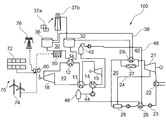
次に図1を参照すると、本発明の1つの実施形態による電気エネルギー蓄積システム100(以下では「システム100」と称する)が略示されている。図1に示した実施形態には、システム100が最も簡単な形態で示されており、このシステムには、ヒートポンプサイクル10と、水蒸気サイクル20と、高温側の蓄熱システムである第1蓄熱システム30と、低温側の蓄熱システムである第2蓄熱システム40とを含み、これらの蓄熱システムはそれぞれ、ヒートポンプサイクル10および水蒸気サイクル20と相互接続されている。システム100にはさらに、第1蓄熱システム30と作動的に接続された電気ヒータ装置50が含まれている。さらにシステム100には、過剰な電気を調整する電力調整装置60も含まれており、この過剰な電気は熱エネルギーへ変換され、必要に応じて活用するために蓄積される。
Referring now to FIG. 1, there is schematically illustrated an electrical energy storage system 100 (hereinafter referred to as “
1つの実施形態によれば、ヒートポンプサイクル10は、亜臨界サイクル、遷臨界サイクルおよび超臨界サイクルとして構成されたサイクルを有する既知のヒートポンプサイクル10を含むことができる。図1に示されている1つの実施形態によれば、ヒートポンプサイクル10には、第1作動流体を圧縮するための圧縮器18と、圧縮器18の下流に配置された熱交換器12と、熱交換器12の下流に配置された膨張器15と、熱交換器12と流体的に接続された蒸発器/ヒータ14とが含まれており、この蒸発器/ヒータ14は、膨張器15と、ヒートポンプサイクル10の低圧側の圧縮器18との間に配置されている。
According to one embodiment,
さらに図1に示されている実施形態によれば、熱交換器12と膨張器15との間ではヒートポンプサイクル10の高圧側であって、圧縮器18と蒸発器/ヒータ14との間ではヒートポンプサイクル10の低圧側に、流体連通状態で復熱器13を配置することができる。このような配置によれば、復熱器13は、高圧作動流体から低圧作動流体へ熱エネルギーを移送する。
Further according to the embodiment shown in FIG. 1, between the
図1に示されている実施形態によれば、水蒸気サイクル20は順番に、蒸気タービン21と、蒸気タービン21から排出された蒸気を凝縮する凝縮器22と、凝縮された水を加圧する凝縮ポンプ23と、低温蓄熱器へ熱を移送する第1温水器26と、蒸気タービン21に戻すべき蒸気をサイクルで発生させる第1ボイラ29とを有している。
According to the embodiment shown in FIG. 1, the
図1に示されている実施形態によれば、蒸気タービン21を多段式蒸気タービン21とすることができ、水蒸気サイクルは、抽出蒸気管路24を介して抽出された蒸気によって凝縮物を加熱する第2温水器28を含む。好ましくは、流体の流れでみて第1ボイラ29と並列に、第2温水器28の下流にさらに別の第2ボイラ27が配置されている。第2温水器28と第2ボイラ27は双方ともに、水蒸気サイクル20に補助エネルギーを供給するために利用することができ、または高温側の蓄熱システム30からの熱入力がないときに、水蒸気サイクル20を作動させるために利用することができる。
According to the embodiment shown in FIG. 1, the
図1に示されている実施形態によれば、第1熱流体を含む第1蓄熱システム30は、高温側の蓄熱システムである。第1蓄熱システム30(「高温側の蓄熱システム30」とも称する)には、高温側の第1低温蓄熱タンク32と高温側の第1高温蓄熱タンク36とが含まれており、これらはヒートポンプサイクル10の熱交換器12を通過する第1流体管路34によって、流体的に接続されている。熱交換器12は、第1熱流体を中庸な温度たとえば約300℃〜400℃まで加熱する。第2流体管路38によって高温側の第1高温蓄熱タンク36が、第1の蒸気ボイラ29を介して高温側の第1低温蓄熱タンク32と接続されている。このようにして、高温側の第1高温蓄熱タンク36からの熱エネルギーを、水蒸気サイクル20におけるエネルギー源として利用することができる。この実施形態では高温側の第1高温蓄熱タンク36は、熱流体を保管するように構成されているだけであるが、別の実施形態によれば高温側の第1高温蓄熱タンク36は、付加的に熱保持手段を含んでおり、たとえば熱吸収性の金属、岩石、または熱を長期にわたり保持可能な他の鉱物などを含んでいる。さらに別の実施形態によれば、高温側の蓄熱システム30は、低温流体と高温流体の混合を防止する材料で充填された、ただ1つの蓄熱タンクを含むようにしてもよい。この分野で知られているように、日中、ヘリオスタット37aおよび受光装置37bによって第1熱流体を加熱することができ、タンク装置32,36を利用して蓄積することができる。
According to the embodiment shown in FIG. 1, the first
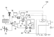
図1の実施形態によれば、第1流体管路34中、高温側の第1低温蓄熱タンク32と第1高温蓄熱タンク36との間で、ヒートポンプサイクル10の熱交換器12の下流において、第1蓄熱システム30に作動的に電気ヒータ装置50を接続することができる。電気ヒータ装置50は、中庸な温度まで加熱された第1熱流体を受け取り、この熱流体を予め定められた温度たとえば約500℃〜600℃までさらに加熱する。ただし、図2に示されているように別の実施形態によれば、蓄熱システム30は、第1の低温蓄熱タンク32と高温蓄熱タンク36との間において、電気ヒータ装置50の上流であり熱交換器12の下流に、第3蓄熱タンク39を含むこともでき、中庸な温度まで加熱された第1熱流体をこの第3蓄熱タンク39内に蓄積させる。この第3蓄熱タンク39を、バッファとして動作するように設置することができ、ヒートポンプサイクル10の動作と電気的な加熱動作とを、2つのチャージサイクルを第1蓄熱システム30とは別個に動作させる必要がある場合に、分離することができる。これによって、買い入れる電気の価格の変動を巧みに利用できるようになる。
According to the embodiment of FIG. 1, in the first
図1に示されている実施形態によれば、第2熱流体を含む第2蓄熱システム40は、低温側の蓄熱システムである。第2蓄熱システム40には、低温側の第2高温蓄熱タンク46と低温側の第2低温蓄熱タンク42とが含まれており、これらはヒートポンプサイクル10の蒸発器/ヒータ14を通過する第3流体管路44によって、流体的に接続されている。さらに第4流体管路48によって低温側の低温蓄熱タンク42は、図1に示されているように少なくとも第1温水器26を介して、低温側の高温蓄熱タンク46と接続されているか、または図3cに示されているように、水蒸気サイクル20の凝縮器22と接続されている。このようにして水蒸気サイクル20からの熱エネルギーを、低温側の低温蓄熱タンク42からの水を加熱して低温側の高温蓄熱タンク46を補給するために、利用することができる。この実施形態では低温側の第1高温蓄熱タンク46は、熱流体を保管するように構成されているだけであるが、別の実施形態によれば低温側の第1高温蓄熱タンク46は、付加的に熱保持手段を含んでおり、たとえば熱吸収性の金属、岩石、または熱を長期にわたり保持可能な他の鉱物などを含んでいる。さらに別の実施形態によれば、低温側の蓄熱システムを、低温側の低温流体と高温流体との混合を防止する材料で充填された、ただ1つの蓄熱タンクによって構成してもよい。
According to the embodiment shown in FIG. 1, the second
この装置によれば電力調整装置60を、1つまたは複数の電源70と電気的に接続された、アルゴリズムベースの電力調整装置60とすることができ、ここで電源70には、太陽光発電システム72、風力発電システム74、送電網76等のうちの少なくとも1つが含まれる。この場合、電力調整装置60は、電源70の過剰電気エネルギーを調整し、過剰電気エネルギーの一部を電気ヒータ装置50へ、さらに一部をヒートポンプサイクル10へ供給して、過剰電気エネルギーを熱エネルギーとして蓄積できるようにする。上述の装置の場合、ヒートポンプサイクル10と電気ヒータ装置50は、電気エネルギーを熱エネルギーへ変換するチャージシステムとして動作する。
According to this device, the
電力調整装置60からの部分的な電気エネルギーを利用し、ヒートポンプサイクル10の圧縮器18を駆動して熱エネルギーを発生させ、これを高温側の蓄熱システム30に供給して蓄積する。さらに別の部分的な電気エネルギーは、電力調整装置60を介して電気ヒータ装置50へ供給され、熱エネルギーに変換されて、高温側の蓄熱システム30にさらに蓄積され、これによって第1熱流体の最高要求温度たとえば約500℃〜600℃に達する。さらに水蒸気サイクル20は、蒸気タービン21を利用して発電機を駆動することによって、高温側の蓄熱システム30内の熱エネルギーの蓄積を電気に変換するディスチャージシステムである。さらに水蒸気サイクル20を利用して、低温側の蓄熱システムに低温エネルギーを補給することができ、これをヒートポンプサイクル10によって利用することができる。
The partial electric energy from the electric
次に図3A〜図3Bを参照すると、システム100が例示されており、これによればシステム100のチャージとディスチャージが描かれている。1つの実施形態に従い、図3aにはシステム100のチャージ動作が示されており、図3bおよび図3cにはシステム100のディスチャージ動作が示されている。チャージサイクルはたとえば日中に行うことができ、ディスチャージサイクルはたとえば夜間に行うことができる。さらにチャージサイクル手段は、第1熱流体を予め定められた温度まで加熱し、それを第1蓄熱システム(30)に蓄積する。同様にディスチャージサイクル手段は、システム100を動作させるために、第1熱流体の熱を利用する。
Referring now to FIGS. 3A-3B, a
一例として図3aに示されているような、遷臨界作動流体を用いたチャージサイクルの方法(濃く描かれた線およびコンポーネント)には、以下のステップが含まれている。最初に、種々の電源70からの過剰な電気を電力調整装置60によって調整し、一部はヒートポンプサイクル10を駆動し、一部は電気ヒータ装置50へ供給する。ヒートポンプサイクル10において電気によりモータを駆動し、これにより圧縮器18は、ヒートポンプサイクル10の第1作動流体を圧縮して超臨界状態にすることができ、圧縮器18の下流に配置された熱交換器12により回収される第1蓄積媒体を、この媒体により許容される最高温度に到達させる。
A method of charge cycle (dark lines and components) using a transcritical working fluid, as shown by way of example in FIG. 3a, includes the following steps. First, excess electricity from the
続く復熱ステップにおいて、圧縮器18の出口圧力を制限するために、冷却された高圧の第1作動流体を用いて、復熱器13内の低圧作動流体を予備加熱する。さらに、冷却された第1作動流体を膨張器15内で膨張させ、この膨張器15は、第1作動流体の圧力を絞って低圧にする。その後、蒸発器/ヒータ14において、作動流体を予備加熱し/蒸発させ、ついで加熱してから、圧縮器へ戻す。この加熱および蒸発のステップを、周囲からの熱によって実施することができ、または、低温側の第2蓄熱サイクル40からの熱を利用して実施することができ、これによってヒートポンプサイクル10の効率が上昇する。図3aに示したチャージングモードにおいてヒートポンプサイクル10は、第2蓄熱システム40の2つのタンクである第2低温蓄熱タンク42と第2高温蓄熱タンク46との温度差として蓄積された熱を、いっそう高い温度に移行させる。この場合、低温タンク(タンク42)は約30℃〜約60℃の範囲にあり、高温タンク(タンク46)は約80℃〜約120℃の範囲にあり、いっそう高い温度とは具体的には、第1蓄熱システム30の2つのタンクである第1低温蓄熱タンク32と第1高温蓄熱タンク36における約265℃〜約565℃の温度差で表される温度である。
In a subsequent recuperation step, the cooled high pressure first working fluid is used to preheat the low pressure working fluid in the
たとえば日中を考えると、このチャージサイクルの終了時点で、第2温水タンク46は空となり、第2冷水タンク42は満水となる。
Considering, for example, the daytime, at the end of this charge cycle, the second
ただし、100〜300バールの圧力において300℃〜400℃を超える温度で動作可能な圧縮器とヒートポンプを製造するのは難しく、かつコストがかかるので、ヒートポンプサイクル10は、ヒートポンプサイクル10の標準的なコンポーネントを利用して達成可能な制限温度すなわち約300℃〜400℃までならば動作するように構成されている。
However, since it is difficult and costly to manufacture a compressor and a heat pump that can operate at a temperature of 300 to 400 ° C. at a pressure of 100 to 300 bar, the
この温度よりも高い温度については、電気ヒータ装置50を用いて第1蓄熱システム(30)の第1熱流体を加熱することができる。この場合、電気エネルギーの一部は、電力調整装置60により調整されて電気ヒータ装置50へ供給され、熱エネルギーに変換されて、高温側の蓄熱システム30にさらに蓄積され、これによって第1熱流体の最高要求温度たとえば約500℃〜600℃に到達させる。
For temperatures above this temperature, the
一例として図3bで示したような、ディスチャージサイクルのための方法(濃く描かれた線およびコンポーネント)には、以下のステップが含まれている。水蒸気サイクル20は、第1蓄熱システム30の熱を利用して蒸気を発生させ、さらに上述のようにして電気を発生させる。さらに第2蓄熱システム40を、ディスチャージサイクル中、予備加熱することができ、上述のようにその熱を、ヒートポンプサイクル10によるチャージサイクル中に利用することができる。このようにするために1つの実施形態によれば、第2低温蓄熱タンク42からの低温側の第2熱流体を、水蒸気サイクル20の第1温水器26を用いて加熱することができ、その後、図3bに示されているように、第4流体管路48を介して第2高温蓄熱タンク46へ戻され、それによって約30℃〜約80℃の第2低温熱流体の温度が達成される。ただし別の実施形態によれば、図3cに示されているように(濃い線およびコンポーネント)、低温側の第2熱流体は、この熱を水蒸気サイクル20の凝縮器から22からとることができ、この場合、第1温水器26の代わりに凝縮器22を利用して第2低温蓄熱タンク42を加熱することができ、その後、第5流体管路49を介して第2高温蓄熱タンク46へ戻され、それによって約30℃〜約50℃の第2熱流体の温度が達成される。図3cの実施形態を適用できる理由は、CSPにおいて一般に用いられている空冷凝縮器たとえば凝縮器22は水冷よりも高い動作温度を有しており、したがって予備加熱トレインよりもむしろ空冷凝縮器を用いると、チャージサイクルのためにいっそう効率的に低温の熱が交換されるようになる、ということによるものである。
The method (dark lines and components) for the discharge cycle, as shown by way of example in FIG. 3b, comprises the following steps. The
ヒートポンプサイクル10の熱流体および作動流体を、システム100の要求に合わせて適合させることができ、1つの実施形態によれば、高温側の第1熱流体を、270℃〜565℃の温度範囲で作動させ、238℃の凝固点を有する溶融塩(60%のNaNO3,40%のKNO3)とすることができる一方、低温側の第2熱流体を、加圧されたまたはされていない水とすることができ、あるいは油、合成油、鉱物油とすることができる。同時に作動流体は、遷臨界チャージサイクルのためにはCO2が選択され、その理由は、CO2は、非可燃性、最高温度での非劣化性、および1000バールまでの圧縮可能性、という適切な物理特性を有するからである。別の選択肢として、作動流体を空気としてもよい。
The thermal and working fluids of the
本発明のシステム100は、既述のように様々な領域において有利である。このシステムは、代替となる改善されたエネルギー蓄積および放出システムであって、このシステムは、過剰な電気エネルギーを利用することができ、標準的なコンポーネントを利用して溶融塩の目標温度を経済的な手法で達成することができる。このことは、本発明によらなければ著しくコストがかかるし、または理論的に不可能である。
The
本発明の特定の実施形態に関する既述の説明は、例示および説明を目的として開示されたものである。それらは網羅的であることを意図したものでもないし、または本発明をここで開示した厳密な形態に限定することを意図したものでもなく、これまで述べてきた教示内容からすれば、多数の改良や変形が可能であるのは明らかである。これらの実施形態は、本発明の原理およびそれらの実際の適用を最もわかりやすく説明できるようにする目的で、さらにそれによって、他の当業者が個々に意図どおりに利用するのに適した種々の変形と合わせて、本発明および種々の実施形態を最良のかたちで活用できるようにする目的で、選択し説明してきたものである。状況によって示唆されるように、または好適であるとされるように、様々な省略や等価のものによる置き換えが想定されるが、それらが意図するのは、本発明の特許請求の範囲の着想または範囲から逸脱することなく、適用または実施を網羅するということである。 The foregoing descriptions of specific embodiments of the present invention have been disclosed for purposes of illustration and description. They are not intended to be exhaustive, or to limit the invention to the precise forms disclosed herein, and the teachings set forth above provide a number of improvements. Obviously, it can be modified. These embodiments are intended to provide the best understanding of the principles of the invention and their practical application, and thereby allow various skilled artisans to individually and individually utilize it as intended. It has been chosen and described in conjunction with variations in order to best utilize the invention and various embodiments. Substitutions with various abbreviations and equivalents are envisioned, as suggested by the circumstances, or as preferred, and are intended to be conceived of the inventive concept or scope of the claims. It is meant to cover an application or implementation without departing from the scope.
100 電気エネルギー蓄積および放出システム
10 ヒートポンプサイクル
12 熱交換器
13 復熱器
14 蒸発器/ヒータ
15 膨張器
18 圧縮器
20 水蒸気サイクル
21 蒸気タービン
22 凝縮器
23 凝縮ポンプ
24 抽出管路
26 第1温水器
27 第2蒸発器
28 第2温水器
29 第1ボイラ
30 第1蓄熱システム
32 第1低温蓄熱タンク
34 第1流体管路
36 第1高温蓄熱タンク
37a ヘリオスタット
37b 受光装置
38 第2流体管路
39 第3蓄熱タンク
40 第2蓄熱システム
42 第2低温蓄熱タンク
44 第3流体管路
46 第2高温蓄熱タンク
48 第4流体管路
49 第5流体管路
50 電気ヒータ装置
60 電力調整装置
70 電源
72 太陽光発電システム
74 風力発電システム
76 送電網
100 Electric Energy Storage and
Claims (10)
第1作動流体を含むヒートポンプサイクル(10)と、
第2作動流体を含む水蒸気サイクル(20)と、
第1熱流体を含む第1蓄熱システム(30)と、
第2熱流体を含む第2蓄熱システム(40)と、
電気ヒータ装置(50)と、
電力調整装置(60)と
が設けられており、
前記第1蓄熱システム(30)は、前記ヒートポンプサイクル(10)および前記水蒸気サイクル(20)と流体的に接続されており、前記第1熱流体を含む第1蓄熱システム(30)は、第1低温蓄熱タンク(32)と、該第1低温蓄熱タンク(32)に流体的に接続された第1高温蓄熱タンク(36)とを含み、
前記第2蓄熱システム(40)は、前記ヒートポンプサイクル(10)および前記水蒸気サイクル(20)に流体的に接続されており、前記第2熱流体は、第2低温蓄熱タンク(42)と、該第2低温蓄熱タンク(42)に流体的に接続された第2高温蓄熱タンク(46)とを含み、
前記電気ヒータ装置(50)は、前記第1低温蓄熱タンク(32)と前記第1高温蓄熱タンク(36)との間で、前記第1蓄熱システム(30)に作動的に接続されており、
前記電力調整装置(60)は、1つまたは複数の電源と電気的に接続されており、該電源の過剰電気エネルギーを調整して、該過剰電気エネルギーの一部を前記電気ヒータ装置(50)へ、一部を前記ヒートポンプサイクル(10)へ供給し、前記過剰電気エネルギーを、前記第1熱流体における熱エネルギーとして蓄積可能にする、
電気エネルギー蓄積および放出システム(100)。 In an electrical energy storage and release system (100) for storing electrical energy as thermal energy,
A heat pump cycle (10) including a first working fluid;
A steam cycle (20) including a second working fluid;
A first heat storage system (30) including a first heat fluid;
A second heat storage system (40) including a second heat fluid;
An electric heater device (50),
A power conditioner (60) is provided,
The first heat storage system (30) is fluidly connected to the heat pump cycle (10) and the steam cycle (20), and the first heat storage system (30) including the first heat fluid is the first heat storage system (30). A low temperature heat storage tank (32) and a first high temperature heat storage tank (36) fluidly connected to the first low temperature heat storage tank (32);
The second heat storage system (40) is fluidly connected to the heat pump cycle (10) and the steam cycle (20), the second heat fluid being a second low temperature heat storage tank (42); A second high temperature heat storage tank (46) fluidly connected to the second low temperature heat storage tank (42);
The electric heater device (50) is operatively connected to the first heat storage system (30) between the first low temperature heat storage tank (32) and the first high temperature heat storage tank (36),
The power adjustment device (60) is electrically connected to one or more power supplies, adjusts excess electric energy of the power supplies, and partially transfers the excess electric energy to the electric heater device (50). To the heat pump cycle (10) so that the excess electrical energy can be stored as thermal energy in the first thermal fluid.
An electrical energy storage and release system (100).
前記第1作動流体を圧縮する圧縮器(18)と、
該圧縮器(18)の下流に配置された熱交換器(12)と、
該熱交換器(12)と流体的に接続された蒸発器/ヒータ(14)と
を含み、
前記ヒートポンプサイクル(10)は、前記熱交換器(12)を通過する第1流体管路(34)を介して、前記第1蓄熱システム(30)に流体的に接続されており、前記第1作動流体の熱が、前記第1低温蓄熱タンク(32)から到来する前記第1熱流体に供給され、前記第1熱流体は、中庸な温度値となって、前記熱交換器(12)の下流に配置された電気的加熱源(50)に供給され、
前記ヒートポンプサイクル(10)は、前記蒸発器/ヒータ(14)を通過する第3流体管路(44)を介して、前記第2蓄熱システム(40)と流体的に接続されており、前記第2高温蓄熱タンク(46)から到来する前記第2熱流体から熱を受け取る、
請求項1記載の電気エネルギー蓄積および放出システム(100)。 The heat pump cycle (10) is
A compressor (18) for compressing the first working fluid,
A heat exchanger (12) arranged downstream of the compressor (18),
An evaporator / heater (14) in fluid connection with the heat exchanger (12),
The heat pump cycle (10) is fluidly connected to the first heat storage system (30) via a first fluid line (34) passing through the heat exchanger (12), The heat of the working fluid is supplied to the first heat fluid coming from the first low temperature heat storage tank (32), the first heat fluid has a moderate temperature value, and the heat exchanger (12) receives heat. Is supplied to an electric heating source (50) arranged downstream,
The heat pump cycle (10) is fluidly connected to the second heat storage system (40) via a third fluid line (44) passing through the evaporator / heater (14), 2 receives heat from the second hot fluid coming from the high temperature heat storage tank (46),
An electrical energy storage and release system (100) according to claim 1.
蒸気を膨張させる蒸気タービン(21)と、
該蒸気タービン(21)の下流に配置された凝縮器(22)と、
該凝縮器(22)の下流に配置された第1温水器(26)と、
該第1温水器(26)の下流に配置され、当該水蒸気サイクル(20)の水を蒸気に変換するボイラ(29)と
を含み、
前記水蒸気サイクル(20)は、前記ボイラ(29)を通過する第2流体管路(38)を介して、前記第1蓄熱システム(30)と流体的に接続されており、前記第1熱流体の熱を前記水蒸気サイクル(20)へ供給し、
前記水蒸気サイクル(20)は、前記第1温水器(26)を通過する第4流体管路(48)を、または前記凝縮器(22)を通過する第5流体管路(49)を、少なくとも介して、前記第2蓄熱システム(40)と流体的に接続されており、前記第2低温蓄熱タンク(42)から到来する前記第2熱流体を加熱する、
請求項1または2記載の電気エネルギー蓄積および放出システム(100)。 The steam cycle (20) is
A steam turbine (21) for expanding steam,
A condenser (22) arranged downstream of the steam turbine (21);
A first water heater (26) arranged downstream of the condenser (22),
It arranged downstream of the first water heater (26), and a boiler (29) for converting the water in the steam cycle (20) to steam,
The steam cycle (20) is fluidly connected to the first heat storage system (30) via a second fluid line (38) passing through the boiler (29), and the first thermal fluid Of heat to the steam cycle (20),
The steam cycle (20) comprises at least a fourth fluid line (48) passing through the first water heater (26) or a fifth fluid line (49) passing through the condenser (22). Via which it is fluidly connected to the second heat storage system (40) and heats the second heat fluid coming from the second low temperature heat storage tank (42).
An electrical energy storage and release system (100) according to claim 1 or 2.
前記抽出管路(24)は、前記水蒸気サイクル(20)内で前記第1温水器(26)の下流に配置された第2温水器(28)と接続されていて、抽出蒸気により前記水蒸気サイクル(20)内の水をさらに加熱可能である、
請求項3記載の電気エネルギー蓄積および放出システム。 The steam turbine (21) is a multi-stage steam turbine (21) provided with an extraction pipe line (24), and the extraction pipe line (24) extracts steam from an intermediate stage of the steam turbine (21). Is configured and arranged as
The extraction pipeline (24) is connected to a second water heater (28) arranged downstream of the first water heater (26) in the water vapor cycle (20), and the water vapor cycle is performed by extraction steam. The water in (20) can be further heated,
An electrical energy storage and release system according to claim 3.
請求項1乃至4のいずれかに記載の電気エネルギー蓄積および放出システム。 The power conditioner (60) is an algorithm-based power conditioner (60), which comprises a solar thermal power generation system (72), a wind power generation system (74), a power grid (76) and Automated to utilize excess electrical energy of a power supply (70) including at least one of the same means,
An electrical energy storage and release system according to any of claims 1 to 4 .
請求項2に記載の電気エネルギー蓄積および放出システム。 Wherein the first thermal storage system (30) between said first said first high temperature heat storage tank and the low temperature heat storage tank (32) (36), upstream in and the heat exchanger of the electric heater device (50) Including a third heat storage tank (39) arranged downstream of (12), and storing the first heat fluid heated to a moderate temperature in the third heat storage tank (39),
An electrical energy storage and release system according to claim 2 .
請求項1乃至6のいずれかに記載の電気エネルギー蓄積および放出システム。 The heat pump cycle (10) is a transcritical heat pump cycle (10),
An electrical energy storage and release system according to any of claims 1 to 6 .
請求項1乃至6のいずれかに記載の電気エネルギー蓄積および放出システム。 The heat pump cycle (10) is a supercritical heat pump cycle (10), and the first working fluid is in a supercritical state throughout the heat pump cycle (10) .
An electrical energy storage and release system according to any of claims 1 to 6 .
請求項1乃至8のいずれかに記載の電気エネルギー蓄積および放出システム。 The first thermal fluid is a molten salt,
An electrical energy storage and release system according to any of claims 1-8 .
請求項1乃至9のいずれかに記載の電気エネルギー蓄積および放出システム。 The second thermal fluid is one of water, pressurized water, oil, synthetic oil and mineral oil.
An electrical energy storage and release system according to any of claims 1-9 .
Applications Claiming Priority (2)
| Application Number | Priority Date | Filing Date | Title |
|---|---|---|---|
| EP15153755.2 | 2015-02-04 | ||
| EP15153755 | 2015-02-04 |
Publications (2)
| Publication Number | Publication Date |
|---|---|
| JP2016142272A JP2016142272A (en) | 2016-08-08 |
| JP6696785B2 true JP6696785B2 (en) | 2020-05-20 |
Family
ID=52469620
Family Applications (1)
| Application Number | Title | Priority Date | Filing Date |
|---|---|---|---|
| JP2016019806A Expired - Fee Related JP6696785B2 (en) | 2015-02-04 | 2016-02-04 | Electrical energy storage and release system |
Country Status (11)
| Country | Link |
|---|---|
| US (1) | US9951979B2 (en) |
| EP (1) | EP3054155B1 (en) |
| JP (1) | JP6696785B2 (en) |
| CN (1) | CN105890221A (en) |
| DK (1) | DK3054155T3 (en) |
| ES (1) | ES2655713T3 (en) |
| HU (1) | HUE035373T2 (en) |
| MA (1) | MA38821B1 (en) |
| PL (1) | PL3054155T3 (en) |
| PT (1) | PT3054155T (en) |
| TN (1) | TN2016000008A1 (en) |
Families Citing this family (27)
| Publication number | Priority date | Publication date | Assignee | Title |
|---|---|---|---|---|
| US10094219B2 (en) | 2010-03-04 | 2018-10-09 | X Development Llc | Adiabatic salt energy storage |
| WO2014052927A1 (en) | 2012-09-27 | 2014-04-03 | Gigawatt Day Storage Systems, Inc. | Systems and methods for energy storage and retrieval |
| CN106224041B (en) * | 2016-09-30 | 2018-06-26 | 西安热工研究院有限公司 | A kind of electric heating energy-storage system |
| CN106322485A (en) * | 2016-09-30 | 2017-01-11 | 西安热工研究院有限公司 | Thermoelectricity energy storage distributed heat supply system |
| CN106224040B (en) * | 2016-09-30 | 2017-11-14 | 西安热工研究院有限公司 | A kind of electric heating energy-storage polygenerations systeme |
| US10233833B2 (en) | 2016-12-28 | 2019-03-19 | Malta Inc. | Pump control of closed cycle power generation system |
| US10233787B2 (en) | 2016-12-28 | 2019-03-19 | Malta Inc. | Storage of excess heat in cold side of heat engine |
| US11053847B2 (en) | 2016-12-28 | 2021-07-06 | Malta Inc. | Baffled thermoclines in thermodynamic cycle systems |
| US10221775B2 (en) | 2016-12-29 | 2019-03-05 | Malta Inc. | Use of external air for closed cycle inventory control |
| US10436109B2 (en) | 2016-12-31 | 2019-10-08 | Malta Inc. | Modular thermal storage |
| PL3379040T3 (en) * | 2017-03-20 | 2021-07-05 | Lumenion Gmbh | Power plant for generating electric power and a method for operating a power plant |
| EP3444448A1 (en) | 2017-08-18 | 2019-02-20 | General Electric Technology GmbH | System and method for converting electric energy into thermal energy and for storing thermal energy |
| EP3712549B1 (en) * | 2017-11-16 | 2023-09-06 | IHI Corporation | Energy storage device |
| DE102018207195A1 (en) * | 2018-05-09 | 2019-11-14 | Robert Bosch Gmbh | Energy system for storage and supply of electricity and heat |
| CN109184831B (en) * | 2018-10-17 | 2023-10-20 | 中国船舶重工集团公司第七0三研究所 | Energy supply side multi-energy switching and decoupling type heat energy storage multi-energy supply system |
| DE102019206155A1 (en) | 2019-04-30 | 2020-11-05 | Thyssenkrupp Ag | Process and plant for the production of vinyl chloride from 1,2-dichloroethane |
| WO2021097413A1 (en) | 2019-11-16 | 2021-05-20 | Malta Inc. | Pumped heat electric storage system |
| US11286804B2 (en) * | 2020-08-12 | 2022-03-29 | Malta Inc. | Pumped heat energy storage system with charge cycle thermal integration |
| US11480067B2 (en) | 2020-08-12 | 2022-10-25 | Malta Inc. | Pumped heat energy storage system with generation cycle thermal integration |
| WO2022036098A1 (en) * | 2020-08-12 | 2022-02-17 | Malta Inc. | Pumped heat energy storage system with steam cycle |
| US11454167B1 (en) | 2020-08-12 | 2022-09-27 | Malta Inc. | Pumped heat energy storage system with hot-side thermal integration |
| US11396826B2 (en) | 2020-08-12 | 2022-07-26 | Malta Inc. | Pumped heat energy storage system with electric heating integration |
| US11486305B2 (en) | 2020-08-12 | 2022-11-01 | Malta Inc. | Pumped heat energy storage system with load following |
| DE102020131706A1 (en) | 2020-11-30 | 2022-06-02 | Man Energy Solutions Se | System and method for storing and delivering electrical energy with its storage as thermal energy |
| DE102021112050A1 (en) | 2021-05-07 | 2022-11-10 | Deutsches Zentrum für Luft- und Raumfahrt e.V. | Method of operating a memory system, memory system, control program and computer-readable medium |
| KR102457328B1 (en) * | 2021-11-18 | 2022-10-21 | 김효찬 | Generating Apparatus Using Residual Power |
| CN114484933B (en) * | 2022-03-03 | 2023-12-01 | 东北电力大学 | Carbon dioxide transcritical electricity storage coupling solar heat storage and carbon dioxide storage circulation system device and system method |
Family Cites Families (24)
| Publication number | Priority date | Publication date | Assignee | Title |
|---|---|---|---|---|
| US4089744A (en) | 1976-11-03 | 1978-05-16 | Exxon Research & Engineering Co. | Thermal energy storage by means of reversible heat pumping |
| JPS63253102A (en) * | 1987-04-08 | 1988-10-20 | Mitsubishi Heavy Ind Ltd | Compound generating system |
| JPS63253101A (en) * | 1987-04-08 | 1988-10-20 | Mitsubishi Heavy Ind Ltd | Compound generating system |
| US6892522B2 (en) * | 2002-11-13 | 2005-05-17 | Carrier Corporation | Combined rankine and vapor compression cycles |
| JP2004340093A (en) * | 2003-05-19 | 2004-12-02 | Hideo Tamai | Solar heat power generator |
| US20080034757A1 (en) * | 2005-05-27 | 2008-02-14 | Skowronski Mark J | Method and system integrating solar heat into a regenerative rankine cycle |
| US8365529B2 (en) | 2006-06-30 | 2013-02-05 | United Technologies Corporation | High temperature molten salt receiver |
| FR2922608B1 (en) * | 2007-10-19 | 2009-12-11 | Saipem Sa | INSTALLATION AND METHOD FOR STORING AND RETURNING ELECTRIC ENERGY USING PISTON GAS COMPRESSION AND RELIEF UNIT |
| GB0808930D0 (en) * | 2008-05-16 | 2008-06-25 | Sunamp Ltd | Energy Storage system |
| WO2010006319A2 (en) * | 2008-07-10 | 2010-01-14 | Infinia Corporation | Thermal energy storage device |
| EP2241737B1 (en) * | 2009-04-14 | 2015-06-03 | ABB Research Ltd. | Thermoelectric energy storage system having two thermal baths and method for storing thermoelectric energy |
| US20100263947A1 (en) | 2009-04-20 | 2010-10-21 | Chris John Reichart | Method for generating electricity from solar panels for an electrical system inside a truck/semi/vehicle |
| DE102009018240A1 (en) | 2009-04-21 | 2010-11-04 | Adensis Gmbh | Photovoltaic system with battery and backup power plant |
| EP2554804B1 (en) * | 2009-06-18 | 2016-12-14 | ABB Research Ltd. | Energy storage system with an intermediate storage tank and method for storing thermoelectric energy |
| EP2525051A1 (en) * | 2011-05-20 | 2012-11-21 | Alstom Technology Ltd | Solar thermal power plant |
| WO2012168251A1 (en) * | 2011-06-07 | 2012-12-13 | Alstom Technology Ltd | Solar thermal power plant |
| DE102011111192B4 (en) | 2011-08-20 | 2019-05-23 | Adensis Gmbh | Time-shifted battery connection in case of emergency request |
| US20130111902A1 (en) * | 2011-11-03 | 2013-05-09 | Mansour Maleki-Ardebili | Solar power system and method of operating a solar power system |
| EP2602443A1 (en) | 2011-12-08 | 2013-06-12 | Alstom Technology Ltd | Electricity storage |
| EP2653668A1 (en) * | 2012-04-17 | 2013-10-23 | Siemens Aktiengesellschaft | Method for loading and discharging a heat exchanger and assembly for storing and discharging thermal energy suitable for this method |
| EP2667028A1 (en) * | 2012-05-25 | 2013-11-27 | Alstom Technology Ltd | A steam Rankine cycle solar plant and method for operating such plants |
| JP2014092086A (en) * | 2012-11-05 | 2014-05-19 | Hitachi Ltd | Solar heat power plant, and solar heat storage and radiation apparatus |
| JP6800557B2 (en) * | 2013-07-09 | 2020-12-16 | 株式会社アルファプラスパワー | Energy system using external combustion engine |
| CN203964443U (en) * | 2014-05-27 | 2014-11-26 | 珠海格力电器股份有限公司 | Solar air source water source associating heating |
-
2016
- 2016-01-08 TN TN2016000008A patent/TN2016000008A1/en unknown
- 2016-01-29 EP EP16153336.9A patent/EP3054155B1/en not_active Not-in-force
- 2016-01-29 PT PT161533369T patent/PT3054155T/en unknown
- 2016-01-29 HU HUE16153336A patent/HUE035373T2/en unknown
- 2016-01-29 PL PL16153336T patent/PL3054155T3/en unknown
- 2016-01-29 MA MA38821A patent/MA38821B1/en unknown
- 2016-01-29 DK DK16153336.9T patent/DK3054155T3/en active
- 2016-01-29 ES ES16153336.9T patent/ES2655713T3/en active Active
- 2016-02-01 US US15/012,155 patent/US9951979B2/en not_active Expired - Fee Related
- 2016-02-04 CN CN201610078684.6A patent/CN105890221A/en active Pending
- 2016-02-04 JP JP2016019806A patent/JP6696785B2/en not_active Expired - Fee Related
Also Published As
| Publication number | Publication date |
|---|---|
| JP2016142272A (en) | 2016-08-08 |
| TN2016000008A1 (en) | 2017-07-05 |
| CN105890221A (en) | 2016-08-24 |
| US20160222830A1 (en) | 2016-08-04 |
| MA38821A1 (en) | 2016-11-30 |
| PT3054155T (en) | 2018-01-19 |
| EP3054155A1 (en) | 2016-08-10 |
| US9951979B2 (en) | 2018-04-24 |
| PL3054155T3 (en) | 2018-08-31 |
| ES2655713T3 (en) | 2018-02-21 |
| EP3054155B1 (en) | 2017-12-20 |
| MA38821B1 (en) | 2017-07-31 |
| HUE035373T2 (en) | 2018-05-02 |
| DK3054155T3 (en) | 2018-01-29 |
Similar Documents
| Publication | Publication Date | Title |
|---|---|---|
| JP6696785B2 (en) | Electrical energy storage and release system | |
| CN112985145B (en) | Energy storage device and method based on carbon dioxide gas-liquid phase change | |
| EP2241737B1 (en) | Thermoelectric energy storage system having two thermal baths and method for storing thermoelectric energy | |
| US7964787B2 (en) | Hybrid solar power generator | |
| CN112985144B (en) | Multistage compression energy storage device and method based on carbon dioxide gas-liquid phase change | |
| US8624410B2 (en) | Electricity generation device with several heat pumps in series | |
| CN112880451A (en) | CO based on supplemental external energy2Gas-liquid phase change energy storage device and method | |
| EP2942492B1 (en) | Electrical energy storage and discharge system | |
| US20120255302A1 (en) | Heating, cooling and power generation system | |
| US20150218969A1 (en) | Method for charging and discharging a heat accumulator and system for storing and releasing thermal energy suitable for said method | |
| JP2013507559A (en) | Thermoelectric energy storage system with internal heat exchanger and method for storing thermoelectric energy | |
| US20150075210A1 (en) | Method for charging and discharging a heat accumulator and plant for storing and releasing thermal energy, suitable for this method | |
| WO2019163347A1 (en) | Compressed air energy storage and power generation device | |
| US10006310B2 (en) | Steam power plant with an additional flexible solar system for the flexible integration of solar energy | |
| US20180003084A9 (en) | Thermo-elevation plant and method | |
| EP3093488A1 (en) | Thermal solar power plant comprising a heat storage assembly and corresponding method | |
| CA2835604C (en) | Steam power plant with an additional flexible solar system for the flexible integration of solar energy | |
| US10794369B1 (en) | Solar powered closed loop system and method for powering a cooling device | |
| RU2776000C1 (en) | Method and system for energy conversion | |
| EP3221566A1 (en) | Thermodynamic system for powering an engine using an external thermal energy source |
Legal Events
| Date | Code | Title | Description |
|---|---|---|---|
| RD02 | Notification of acceptance of power of attorney |
Free format text: JAPANESE INTERMEDIATE CODE: A7422 Effective date: 20160418 |
|
| A521 | Request for written amendment filed |
Free format text: JAPANESE INTERMEDIATE CODE: A821 Effective date: 20160425 |
|
| RD04 | Notification of resignation of power of attorney |
Free format text: JAPANESE INTERMEDIATE CODE: A7424 Effective date: 20160425 |
|
| A621 | Written request for application examination |
Free format text: JAPANESE INTERMEDIATE CODE: A621 Effective date: 20190201 |
|
| RD02 | Notification of acceptance of power of attorney |
Free format text: JAPANESE INTERMEDIATE CODE: A7422 Effective date: 20190507 |
|
| A977 | Report on retrieval |
Free format text: JAPANESE INTERMEDIATE CODE: A971007 Effective date: 20191128 |
|
| A131 | Notification of reasons for refusal |
Free format text: JAPANESE INTERMEDIATE CODE: A131 Effective date: 20191206 |
|
| A521 | Request for written amendment filed |
Free format text: JAPANESE INTERMEDIATE CODE: A523 Effective date: 20200114 |
|
| TRDD | Decision of grant or rejection written | ||
| A01 | Written decision to grant a patent or to grant a registration (utility model) |
Free format text: JAPANESE INTERMEDIATE CODE: A01 Effective date: 20200327 |
|
| A61 | First payment of annual fees (during grant procedure) |
Free format text: JAPANESE INTERMEDIATE CODE: A61 Effective date: 20200423 |
|
| R150 | Certificate of patent or registration of utility model |
Ref document number: 6696785 Country of ref document: JP Free format text: JAPANESE INTERMEDIATE CODE: R150 |
|
| LAPS | Cancellation because of no payment of annual fees |