JP6692987B2 - Devices, Systems, and Methods for Patient Monitoring to Predict and Prevent Bed Fall - Google Patents
Devices, Systems, and Methods for Patient Monitoring to Predict and Prevent Bed Fall Download PDFInfo
- Publication number
- JP6692987B2 JP6692987B2 JP2019510665A JP2019510665A JP6692987B2 JP 6692987 B2 JP6692987 B2 JP 6692987B2 JP 2019510665 A JP2019510665 A JP 2019510665A JP 2019510665 A JP2019510665 A JP 2019510665A JP 6692987 B2 JP6692987 B2 JP 6692987B2
- Authority
- JP
- Japan
- Prior art keywords
- individual
- patient
- bed
- intervention
- risk score
- Prior art date
- Legal status (The legal status is an assumption and is not a legal conclusion. Google has not performed a legal analysis and makes no representation as to the accuracy of the status listed.)
- Expired - Fee Related
Links
- 238000000034 method Methods 0.000 title claims description 25
- 238000012544 monitoring process Methods 0.000 title description 24
- 238000004364 calculation method Methods 0.000 claims description 18
- 230000008859 change Effects 0.000 claims description 12
- 230000003044 adaptive effect Effects 0.000 claims description 7
- 229940079593 drug Drugs 0.000 claims description 6
- 239000003814 drug Substances 0.000 claims description 6
- 208000024891 symptom Diseases 0.000 claims description 5
- 238000004590 computer program Methods 0.000 claims description 4
- 230000003930 cognitive ability Effects 0.000 claims description 3
- 230000000977 initiatory effect Effects 0.000 claims description 3
- 206010060860 Neurological symptom Diseases 0.000 claims description 2
- 230000003931 cognitive performance Effects 0.000 claims description 2
- 230000007704 transition Effects 0.000 claims description 2
- 230000002452 interceptive effect Effects 0.000 claims 1
- 206010038743 Restlessness Diseases 0.000 description 28
- 238000012545 processing Methods 0.000 description 27
- 230000005484 gravity Effects 0.000 description 24
- 230000006870 function Effects 0.000 description 14
- 208000001431 Psychomotor Agitation Diseases 0.000 description 9
- 230000006399 behavior Effects 0.000 description 8
- 238000001514 detection method Methods 0.000 description 8
- 230000002265 prevention Effects 0.000 description 8
- 238000004422 calculation algorithm Methods 0.000 description 7
- 238000010586 diagram Methods 0.000 description 6
- 238000011156 evaluation Methods 0.000 description 6
- 230000001133 acceleration Effects 0.000 description 5
- 238000013019 agitation Methods 0.000 description 4
- 230000008569 process Effects 0.000 description 4
- 238000012549 training Methods 0.000 description 4
- 208000019901 Anxiety disease Diseases 0.000 description 3
- 230000009471 action Effects 0.000 description 3
- 238000004458 analytical method Methods 0.000 description 3
- 230000036506 anxiety Effects 0.000 description 3
- 238000013459 approach Methods 0.000 description 3
- 230000036772 blood pressure Effects 0.000 description 3
- 230000001364 causal effect Effects 0.000 description 3
- 230000001419 dependent effect Effects 0.000 description 3
- 230000036541 health Effects 0.000 description 3
- 238000005286 illumination Methods 0.000 description 3
- 230000001771 impaired effect Effects 0.000 description 3
- 230000003993 interaction Effects 0.000 description 3
- 230000001788 irregular Effects 0.000 description 3
- 238000002483 medication Methods 0.000 description 3
- 230000000474 nursing effect Effects 0.000 description 3
- 230000029058 respiratory gaseous exchange Effects 0.000 description 3
- 238000005096 rolling process Methods 0.000 description 3
- 208000019116 sleep disease Diseases 0.000 description 3
- 230000000007 visual effect Effects 0.000 description 3
- 208000028698 Cognitive impairment Diseases 0.000 description 2
- 208000010877 cognitive disease Diseases 0.000 description 2
- 238000010219 correlation analysis Methods 0.000 description 2
- 230000006378 damage Effects 0.000 description 2
- 238000005516 engineering process Methods 0.000 description 2
- 230000000670 limiting effect Effects 0.000 description 2
- 230000003449 preventive effect Effects 0.000 description 2
- 230000004044 response Effects 0.000 description 2
- 230000000284 resting effect Effects 0.000 description 2
- 238000012360 testing method Methods 0.000 description 2
- 208000024827 Alzheimer disease Diseases 0.000 description 1
- 238000012935 Averaging Methods 0.000 description 1
- 206010012289 Dementia Diseases 0.000 description 1
- 208000004547 Hallucinations Diseases 0.000 description 1
- 125000002066 L-histidyl group Chemical group [H]N1C([H])=NC(C([H])([H])[C@](C(=O)[*])([H])N([H])[H])=C1[H] 0.000 description 1
- 206010049565 Muscle fatigue Diseases 0.000 description 1
- 208000018737 Parkinson disease Diseases 0.000 description 1
- 208000004210 Pressure Ulcer Diseases 0.000 description 1
- 206010039897 Sedation Diseases 0.000 description 1
- 230000002776 aggregation Effects 0.000 description 1
- 238000004220 aggregation Methods 0.000 description 1
- 238000013473 artificial intelligence Methods 0.000 description 1
- 230000037147 athletic performance Effects 0.000 description 1
- QVGXLLKOCUKJST-UHFFFAOYSA-N atomic oxygen Chemical compound [O] QVGXLLKOCUKJST-UHFFFAOYSA-N 0.000 description 1
- 230000008901 benefit Effects 0.000 description 1
- 239000008280 blood Substances 0.000 description 1
- 210000004369 blood Anatomy 0.000 description 1
- 230000003139 buffering effect Effects 0.000 description 1
- 230000009194 climbing Effects 0.000 description 1
- 230000001149 cognitive effect Effects 0.000 description 1
- 239000003086 colorant Substances 0.000 description 1
- 238000004891 communication Methods 0.000 description 1
- 239000002131 composite material Substances 0.000 description 1
- 238000012790 confirmation Methods 0.000 description 1
- 238000007796 conventional method Methods 0.000 description 1
- 238000013523 data management Methods 0.000 description 1
- 238000013500 data storage Methods 0.000 description 1
- 230000006735 deficit Effects 0.000 description 1
- 230000001934 delay Effects 0.000 description 1
- 238000013461 design Methods 0.000 description 1
- 238000011161 development Methods 0.000 description 1
- 208000037265 diseases, disorders, signs and symptoms Diseases 0.000 description 1
- 208000035475 disorder Diseases 0.000 description 1
- 230000005802 health problem Effects 0.000 description 1
- 208000015181 infectious disease Diseases 0.000 description 1
- 230000005764 inhibitory process Effects 0.000 description 1
- 230000009191 jumping Effects 0.000 description 1
- 238000003064 k means clustering Methods 0.000 description 1
- 230000008376 long-term health Effects 0.000 description 1
- 238000012423 maintenance Methods 0.000 description 1
- 239000011159 matrix material Substances 0.000 description 1
- 239000000203 mixture Substances 0.000 description 1
- 238000010606 normalization Methods 0.000 description 1
- 230000003287 optical effect Effects 0.000 description 1
- 238000005457 optimization Methods 0.000 description 1
- 229910052760 oxygen Inorganic materials 0.000 description 1
- 239000001301 oxygen Substances 0.000 description 1
- 230000036961 partial effect Effects 0.000 description 1
- 230000005195 poor health Effects 0.000 description 1
- 238000012797 qualification Methods 0.000 description 1
- 230000002829 reductive effect Effects 0.000 description 1
- 238000011160 research Methods 0.000 description 1
- 230000000630 rising effect Effects 0.000 description 1
- 238000012502 risk assessment Methods 0.000 description 1
- 238000013349 risk mitigation Methods 0.000 description 1
- 230000036280 sedation Effects 0.000 description 1
- 239000007787 solid Substances 0.000 description 1
- 238000003860 storage Methods 0.000 description 1
- 239000000126 substance Substances 0.000 description 1
Images


Classifications
-
- G—PHYSICS
- G16—INFORMATION AND COMMUNICATION TECHNOLOGY [ICT] SPECIALLY ADAPTED FOR SPECIFIC APPLICATION FIELDS
- G16H—HEALTHCARE INFORMATICS, i.e. INFORMATION AND COMMUNICATION TECHNOLOGY [ICT] SPECIALLY ADAPTED FOR THE HANDLING OR PROCESSING OF MEDICAL OR HEALTHCARE DATA
- G16H50/00—ICT specially adapted for medical diagnosis, medical simulation or medical data mining; ICT specially adapted for detecting, monitoring or modelling epidemics or pandemics
- G16H50/30—ICT specially adapted for medical diagnosis, medical simulation or medical data mining; ICT specially adapted for detecting, monitoring or modelling epidemics or pandemics for calculating health indices; for individual health risk assessment
-
- G—PHYSICS
- G16—INFORMATION AND COMMUNICATION TECHNOLOGY [ICT] SPECIALLY ADAPTED FOR SPECIFIC APPLICATION FIELDS
- G16H—HEALTHCARE INFORMATICS, i.e. INFORMATION AND COMMUNICATION TECHNOLOGY [ICT] SPECIALLY ADAPTED FOR THE HANDLING OR PROCESSING OF MEDICAL OR HEALTHCARE DATA
- G16H40/00—ICT specially adapted for the management or administration of healthcare resources or facilities; ICT specially adapted for the management or operation of medical equipment or devices
- G16H40/60—ICT specially adapted for the management or administration of healthcare resources or facilities; ICT specially adapted for the management or operation of medical equipment or devices for the operation of medical equipment or devices
- G16H40/63—ICT specially adapted for the management or administration of healthcare resources or facilities; ICT specially adapted for the management or operation of medical equipment or devices for the operation of medical equipment or devices for local operation
-
- G—PHYSICS
- G16—INFORMATION AND COMMUNICATION TECHNOLOGY [ICT] SPECIALLY ADAPTED FOR SPECIFIC APPLICATION FIELDS
- G16H—HEALTHCARE INFORMATICS, i.e. INFORMATION AND COMMUNICATION TECHNOLOGY [ICT] SPECIALLY ADAPTED FOR THE HANDLING OR PROCESSING OF MEDICAL OR HEALTHCARE DATA
- G16H40/00—ICT specially adapted for the management or administration of healthcare resources or facilities; ICT specially adapted for the management or operation of medical equipment or devices
- G16H40/60—ICT specially adapted for the management or administration of healthcare resources or facilities; ICT specially adapted for the management or operation of medical equipment or devices for the operation of medical equipment or devices
- G16H40/67—ICT specially adapted for the management or administration of healthcare resources or facilities; ICT specially adapted for the management or operation of medical equipment or devices for the operation of medical equipment or devices for remote operation
Landscapes
- Engineering & Computer Science (AREA)
- Health & Medical Sciences (AREA)
- Biomedical Technology (AREA)
- Medical Informatics (AREA)
- Public Health (AREA)
- Epidemiology (AREA)
- Primary Health Care (AREA)
- General Health & Medical Sciences (AREA)
- General Business, Economics & Management (AREA)
- Business, Economics & Management (AREA)
- Pathology (AREA)
- Databases & Information Systems (AREA)
- Data Mining & Analysis (AREA)
- Measuring And Recording Apparatus For Diagnosis (AREA)
- Invalid Beds And Related Equipment (AREA)
- Alarm Systems (AREA)
- Medical Treatment And Welfare Office Work (AREA)
- Emergency Alarm Devices (AREA)
Description
本発明は、個人、特に病院内の、又は在宅ケアを受ける患者、を監視するためのデバイスに関し、本デバイスは、ベッド外への人の顕著な転落の予測を可能にするように適応される。本デバイスは、多くの関連のあるリスク因子が規定の閾値を上回ったときに、警報を発する。本発明はさらに、前述のデバイスを組み込んだシステム、及び、個人を監視してベッド転落を予測する方法に関する。 The present invention relates to a device for monitoring an individual, in particular a patient in a hospital or receiving home care, the device being adapted to allow prediction of a significant fall of a person out of bed. .. The device alerts when many relevant risk factors exceed defined thresholds. The invention further relates to a system incorporating the aforementioned device and a method of monitoring an individual to predict bed fall.
転落は、病院において報告される最も一般的な有害事象であり、院内のけがの主な原因となり、入院を長引かせるか、又は複雑なものとすることが多い。救急病院における観察研究の考察は、転落率が1.3から8.9転落/1,000患者日の範囲であることと、高齢者ケア、神経内科、及びリハビリテーションに注目した集団で、より高い転落率が生じることを示す。転落リスク因子に関する幅広い研究及び多くの転落リスク対策器具の進歩にもかかわらず、プロトコルは一貫性なく適用され、リスク因子に対応した介入は標準化されるには程遠い。 Fall is the most common adverse event reported in hospitals and is a major cause of in-hospital injuries, often prolonging hospital stays or complicating them. Observations in the emergency hospital have higher observations for fall rates ranging from 1.3 to 8.9 fall / 1,000 patient days and for populations focusing on geriatric care, neurology and rehabilitation. Indicates that a fall rate will occur. Despite extensive research on fall risk factors and advances in many fall risk mitigation instruments, protocols are applied inconsistently and risk factor interventions are far from standardized.
転落はすべての年齢において起こり得るが、転落は、入院を必要とする緊急の健康問題と組み合わされたときに高齢の人又は高転落リスク集団に属する人に、又は、施設ケア環境への入所を必要とする人に重大なけがをもたらすことが知られている。 Although falls can occur at all ages, falls may occur in older people or those in high fall risk groups when combined with urgent health problems requiring hospitalization, or in admission to an institutional care setting. It is known to cause serious injuries to those in need.
加えて、他の観察研究は、病院におけるすべての転落のうちの60〜70%が、ベッド又はベッドわきの椅子から発生すること、転落の80%を上回る部分が目撃者のいないものであること、及び、約50%が繰り返し転落する患者に発生することを示す。 In addition, other observational studies have shown that 60-70% of all falls in hospitals occur from beds or chairs beside the bed, and more than 80% of falls are witness-free. , And about 50% occur in patients with repeated falls.
患者の健康及び生活の質並びに医療費に対する転落事故の高い影響を鑑みると、ベッド転落事故の数を減らすために、患者監視及び転落防止のための拡縮可能で費用効率の高い解決策を見つけることが最も重要となる。 Given the high impact of fall accidents on patient health and quality of life and on medical costs, find a scalable and cost-effective solution for patient monitoring and fall prevention to reduce the number of bed falls. Is the most important.
従来技術として、ベッド転落事故防止の手段としての看護人サービス、ベッド転落事故防止の手段としてのベッドレール、及び、患者監視のための特定の自動解決策などの解決策が挙げられる。 Prior art includes solutions such as caregiver services as a means of bed fall prevention, bed rails as a means of bed fall prevention, and certain automated solutions for patient monitoring.
看護人サービスは、実現することが困難であり、拡縮可能ではなく、費用効率が高くない。その実現に向けて、病院は典型的には、サービスの高いコストに起因して財政的に負担の重い、病院スタッフ以外から看護人を採用すること、又は、典型的にはスタッフ不足に起因して既に負担の過大なスタッフの責任及び作業負荷を大幅に増やす、病院自体の病院スタッフに看護人の職務を割り当てることの間で選択をしなければならない。加えて、資格をもつスタッフに(医療訓練を必要としない)看護人の任務を割り当てることは、人員の資格及び技量の適切な活用を妨げる。 Nursing services are difficult to implement, not scalable and not cost effective. To that end, hospitals are typically financially burdened by the high cost of services, recruiting nurses from non-hospital staff, or typically due to staff shortages. A choice must then be made between assigning the duties of the nurse to the hospital staff of the hospital itself, which significantly increases the liability and workload of the already overloaded staff. In addition, assigning qualified staff to the duties of a nurse (which does not require medical training) impedes the proper use of personnel qualifications and skills.
その意味で、看護人サービスは、入院患者のベッド転落事故に対する信頼可能な、拡縮可能な、及び費用効率の高い防止技法を実現することに関して、好ましい展望を見せない。 In that sense, Nursing Services does not see a positive outlook on implementing reliable, scalable, and cost-effective prevention techniques for inpatient bed fall accidents.
単一の防止技法としてのベッドレールは、ベッド転落事故の防止を保証するとは思われない。病院におけるベッドからの転落の50〜90%は、ベッドレールが適用されているにもかかわらず発生し、概して、転落を防止することについて成功例が限られることを示す。加えて、ベッドレールの使用は、動揺、恐怖、及び精神錯乱の悪化にも関係する。例えば神経遮断薬の使用により転落を防止するという誤った意図にもかかわらず神経遮断薬を使用する形態の「化学的」抑制は、より高い転落率に関係する。さらに、抑制又はベッドレールの使用は、筋肉疲労、動かないことによる感染症又は床ずれ、及び体調不良をもたらし得る。最後に、患者の運動能力を制限することに関して、検討を必要とされる倫理的要素が存在する。 Bed rails as the sole prevention technique do not appear to guarantee bed fall prevention. Fifty to ninety percent of bed falls in hospitals occur despite the application of bed rails, generally indicating limited success in preventing falls. In addition, the use of bed rails is associated with agitation, fear, and worsening confusion. "Chemical" inhibition of forms that use neuroleptics despite the false intent to prevent falls, for example by using neuroleptics, is associated with higher fall rates. Further, restraint or use of bedrails can lead to muscle fatigue, inactivity infections or bedsores, and poor health. Finally, there are ethical factors that need to be considered regarding limiting the athletic performance of the patient.
技術ベースの製品が看護人サービスに置き換わるように試みることに使用されてきたが、内在する欠点ももつ。いくつかのシステムは、患者を監視するときにいわゆる「eSitter(電子看護器)」をサポートするインテリジェンスをまったく提供せず、このことが並行して監視される患者の数を制限する。このような解決策の拡縮可能性は限られているので、拡大は、追加的なデバイス及び遠隔監視ステーションを必要とする。リアルタイムで転落リスクを自動的に判定するインテリジェンスが実現されていないことは、懸念を高め、転落事故防止の実行可能性に疑念をもたらす。評価される転落リスクは、病院スタッフによる初期の、及び継続的に患者と連絡を取ることにより取得された入力に基づいているが、リアルタイムで患者の連続した自動観察に基づいて更新されることがない。転落リスクの更新は、入所時及び入院中の患者との面会に基づくので、これらの更新は、不正確であり大幅な遅延を伴う傾向があるので、さらに懸念を高める。 While technology-based products have been used to attempt to replace nursing care services, they also have inherent drawbacks. Some systems do not provide any intelligence to support so-called "eSitters" when monitoring patients, which limits the number of patients monitored in parallel. As the scalability of such solutions is limited, the expansion requires additional devices and remote monitoring stations. The lack of real-time intelligence to automatically determine fall risk raises concerns and raises doubts about the feasibility of fall prevention. The assessed fall risk is based on the input obtained by the hospital staff during initial and ongoing contact with the patient, but may be updated based on continuous, automated observation of the patient in real time. Absent. As fall risk updates are based on interviews with patients at the time of admission and in the hospital, these updates tend to be inaccurate and associated with significant delays, further raising concern.
他のシステムは、実際の患者のベッド離床を伴わずに(ブランケットによる又は患者の腕による)部分的なベッド縁部との交差が発生したときに、いつでも、システムが警報を始動させる技術的なアプローチを実現する。これは、誤警報の割合が高くなることにつながる。 Other systems provide a technical way for the system to trigger an alarm whenever a partial bed edge crossing (either by the blanket or by the patient's arm) occurs without the actual bed leaving of the patient. Realize the approach. This leads to a high false alarm rate.
加えて、効果的な予防介入に関係して、これらの技術は、監視及び警報に非常に注目しているが、特定の時点に特定の患者プロファイルが与えられたときに提供されなければならない最適な介入を理解することに注意が払われていない。さらに、医療スタッフが介入しなければならない場合、これらのシステムは、スタッフの人的資源を最適化するために通知されなければならない実際の人を決定することについて、サポートを提供しない。最後に、すべての警報は、転落のリスクが非常に高い、及び、事故の発生が切迫しているときにのみ発され、この時点で、実際に転落を防止する効果的な介入を提供する機会が減らされる。 In addition, in the context of effective preventive interventions, these techniques pay close attention to monitoring and alerting, but the optimum that must be provided at a particular point in time and given a particular patient profile. Attention is paid to understanding different interventions. Moreover, when medical staff must intervene, these systems do not provide support in determining the actual person who must be notified to optimize the staff's human resources. Finally, all alerts are only issued when the risk of a fall is very high and the onset of an accident is imminent, at which point there is an opportunity to actually provide effective interventions to prevent the fall. Is reduced.
WO2013/150523A1は、臨床症状の発現の監視、予測、及び処置について説明する。処置プロトコルを指定された患者とともに使用するための装置及び方法が提供される。センサーが、患者の少なくとも1つの生理学的パラメータを検出する。制御ユニットは、生理学的パラメータを分析する、かつ、患者が処置プロトコルに従ったか否かを判定する信号分析機能を含む。ユーザーインターフェースは、(a)患者が処置プロトコルに従わなかったことを分析機能が特定したことに応答して出力が生成される、生理学的パラメータと患者による処置プロトコルの非遵守性との間の相関、又は、(b)患者が処置プロトコルに従ったことを分析機能が特定したことに応答して出力が生成される、生理学的パラメータと患者による処置プロトコルの遵守性との間の相関を表す、患者に対する出力を生成する。 WO2013 / 150523A1 describes the monitoring, prediction and treatment of the development of clinical symptoms. Devices and methods are provided for use with treatment protocols with designated patients. A sensor detects at least one physiological parameter of the patient. The control unit includes a signal analysis function that analyzes physiological parameters and determines whether the patient has followed the treatment protocol. The user interface includes: (a) Correlation between physiological parameters and patient non-compliance with the treatment protocol produced in response to the analysis function identifying that the patient did not comply with the treatment protocol. Or (b) represents a correlation between a physiological parameter and patient compliance with a treatment protocol, wherein an output is produced in response to the analysis function identifying that the patient has followed the treatment protocol, Generate output for the patient.
動きパターン及び患者のバイタルサインを監視するだけでなく、さらに、データを評価することと、一方で、信頼可能な予測を可能にしながら、他方で、誤警報を最小化するリスクスコアを査定することとを行うことにより、患者のための効果的でありながら注意深いケアを可能にする、患者の監視のためのデバイス、システム、及び方法を提供することが本発明の目的である。 Not only to monitor movement patterns and patient vital signs, but also to evaluate the data and, on the one hand, to assess the risk score that minimizes false alarms, while allowing reliable predictions. It is an object of the present invention to provide a device, system and method for patient monitoring that enables effective yet careful care for a patient by performing
本発明の第1の態様において、個人の個人データと個人の総リスクスコアとを取得するための第1のポートと、取得されたデータに基づいて個人の切迫したベッド転落に関係した予測と個人のベッド転落を防止するための介入のための時間枠とを特定するための介入ユニットと、予測と取得されたデータとに基づいて介入信号を出力するための第2のポートとを備える、個人のベッド転落リスクに関連した個人に対する適応型の介入のためのデバイスが提示される。 In a first aspect of the invention, a first port for obtaining an individual's personal data and an individual's total risk score, and a prediction and an individual related to an individual's imminent bed fall based on the obtained data. An intervening unit for identifying a time frame for intervention to prevent the bed from falling and a second port for outputting an intervention signal based on the prediction and the acquired data. A device for adaptive intervention for individuals associated with the risk of falling of bed is presented.
本発明のさらなる態様において、個人の個人データを提供するための分類ユニットと、個人の総リスクスコアを計算するための計算ユニットと、分類ユニット及び計算ユニットの出力に基づく、個人に対する適応型の介入のためのデバイスとを備える、個人のベッド転落リスクに関連した個人に対する適応型の介入のためのシステムが提示される。 In a further aspect of the invention, a classification unit for providing personal data of an individual, a calculation unit for calculating an individual's total risk score, and an adaptive intervention for the individual based on the outputs of the classification unit and the calculation unit. A system for adaptive intervention for an individual associated with an individual's risk of falling of bed is provided.
本発明の別の一態様において、個人のベッド転落リスクの特定のための方法が提示され、本方法は、個人の個人データを取得するステップと、個人の総リスクスコアを取得するステップと、取得されたデータに基づいて個人の切迫したベッド転落に関係した予測と個人のベッド転落を防止するための介入のための時間枠とを特定するステップと、取得されたデータと予測とに基づいて個人に介入するステップとを有する。 In another aspect of the invention, a method for identifying an individual's bedfall risk is presented, the method comprising: obtaining personal data of an individual; obtaining a total risk score of the individual; Identifying the imminent bed-fall related predictions of the individual based on the captured data and the time frame for the intervention to prevent the individual's bed-fall; and based on the acquired data and the prediction And the step of intervening.
本発明のさらに異なるさらなる一態様において、コンピュータにおいてコンピュータプログラムが実行されたとき、方法のステップをコンピュータが実行することをもたらすプログラムコード手段を備えるコンピュータプログラムが提示される。 In yet another further aspect of the present invention there is presented a computer program comprising program code means which, when executed on a computer, causes the computer to carry out the steps of the method.
ベッド転落リスクの特定のための本発明のデバイス、システム、方法、及びコンピュータプログラムは、介入ユニットが、一方で個人の個人データを考慮し、他方で動きデータと健康記録とに基づいて個人のリスクスコアと能力レベルとを検出するように、及び、ベッド転落を防止するために、個人にどのように効果的に、及び信頼可能に介入するか、データ集合体に基づいて決定するように構成されるという点で上述の従来技術と異なる。 The device, system, method and computer program according to the invention for the identification of the risk of falling of a bed is such that the intervention unit takes into account the personal data of the individual on the one hand and the risk of the individual on the other hand on the basis of movement data and health records. It is configured to detect scores and ability levels, and to make effective decisions on how to reliably and reliably intervene in individuals to prevent bed falls based on a collection of data. This is different from the above-mentioned conventional technique.
本発明の好ましい実施形態は、従属請求項において定義される。請求項に記載された方法が、請求項に記載されたデバイス及び従属請求項において規定されたものと同様の、及び/又は同一の好ましい実施形態を含むことが理解されなければならない。 Preferred embodiments of the invention are defined in the dependent claims. It is to be understood that the claimed methods include preferred embodiments similar and / or identical to those defined in the claimed device and the dependent claims.
好ましくは、介入ユニットが、個人の近傍に配置されたインターフェースにより直接個人に介入信号を出力するように構成される。これは、スタッフ又は他のリソースに任せずに個人に介入するための、最も簡単かつ最も直接的なアプローチである。この直接的な介入が失敗した場合、次のステップが開始され得る。 Preferably, the intervention unit is arranged to output the intervention signal directly to the individual by means of an interface arranged in the vicinity of the individual. This is the simplest and most direct approach to intervening in an individual without relying on staff or other resources. If this direct intervention fails, the next step can be initiated.
有益な実施形態によると、本デバイスは、スタッフのスケジュールに関係したデータを取得するための第3のポートをさらに備える。警報が出された場合、スタッフのスケジュールが考慮され得、最も近い、若しくは手の空いた、又はより低い優先度のタスクを受けたスタッフが、個人を補助するために最初に警報を受ける。 According to an advantageous embodiment, the device further comprises a third port for obtaining data related to staff schedules. When alerted, the staff's schedule may be taken into account and the staff with the closest or available or lower priority task will be alerted first to assist the individual.
有益には介入ユニットは、スタッフのスケジュールと取得されたデータと予測とに基づいて、スタッフメンバーに介入信号を出力するように、及び、個人に対するスタッフの介入を開始させるように構成される。従って、行動が、ケアを受ける人に対するリスクを最小にしながら、スタッフの相応の労力、及び最も効果的な介入を伴って効率化される。 Beneficially, the intervention unit is configured to output an intervention signal to the staff member and to initiate the intervention of the staff on the individual based on the staff's schedule and the acquired data and forecasts. Thus, the behavior is streamlined with a reasonable effort of staff and the most effective intervention, while minimizing the risk to the care recipient.
好ましくは、個人の個人データは、年齢、性別、神経学的症状、症状、身体障害、服薬、転落履歴、心理プロファイルのうちの1つ又は複数を含む。これらのデータは、任意の事例において、個人が収容されるときにケア環境のITシステムに記憶され、従って、個人のリスクスコアの特定のために簡単に利用可能である。 Preferably, the personal data of the individual includes one or more of age, sex, neurological symptoms, symptoms, disability, medication, falling history, and psychological profile. These data are, in any case, stored in the IT system of the care environment when the individual is admitted and are therefore readily available for identification of the individual's risk score.
総リスクスコアは、有益には、個人の個人データを取得することにより、並びに、個人の近傍に、及び/又は個人に接触して配置された少なくとも1つのセンサーからセンサーデータを取得することにより特定される。従って、個人の実際の挙動と長期の健康記録との両方に基づく個人のリスクスコアがカスタマイズされ得、個人のベッド転落のリスクが高確度で予測され得る。 The total risk score is beneficially determined by obtaining personal data of the individual and by obtaining sensor data from at least one sensor located near the individual and / or in contact with the individual. To be done. Thus, an individual's risk score based on both the individual's actual behavior and long-term health records can be customized and the individual's risk of falling to bed can be predicted with high accuracy.
本発明の好ましい実施形態によると、介入ユニットは、総リスクスコアと、所定の時間枠内における総リスクスコアの変化及び/又は推移とに基づいて、個人の個々の能力レベルを区別するように構成され、個人の能力レベルは、認知能力レベル、対話能力レベル、遵守性レベルを含む。異なるレベルが、切迫したベッド転落のリスクの簡単かつ信頼可能な評価を可能にし、互いに簡単に識別され得る。従って、それぞれの介入が開始され得る。 According to a preferred embodiment of the present invention, the intervention unit is arranged to distinguish an individual's individual performance level based on the total risk score and the change and / or transition of the total risk score within a predetermined time frame. The individual ability level includes a cognitive ability level, a dialogue ability level, and a compliance level. Different levels allow a simple and reliable assessment of the risk of impending bed fall and can be easily identified from each other. Therefore, each intervention can be initiated.
認知能力レベルは、総リスクスコアが低いか又は中程度であるが、限られた時間窓内において低速から中程度の速度で増加することに関係する。これは、個人がインターフェースによる直接的な介入により介護され得る可能性が最も高い、最低レベルの介入である。 Cognitive performance levels are associated with low or moderate total risk scores, but increasing at a slow to moderate rate within a limited time window. This is the lowest level of intervention that is most likely for individuals to be cared for by direct interface interventions.
対話能力レベルは、総リスクスコアが低いか又は中程度であるが、限られた時間窓内において大幅に増加することに関係する。この場合、システムが警報を受け、総リスクスコアが増加し続けた場合に警報を発する準備が整う。低下した場合、システムが警報ステータスを下げる。 The level of dialogue ability is associated with a low or moderate total risk score, but a significant increase within a limited time window. In this case, the system is alerted and ready to alert if the total risk score continues to increase. If so, the system lowers the alert status.
遵守性レベルは、総リスクスコアが高いと特定されることに関係する。総リスクスコアが終わりなく高い場合、システムは終わりない警報状態となり、厳しい状況についてスタッフが知らされ続けるようにする。 The compliance level is related to the fact that the total risk score is identified as high. If the total risk score is high endlessly, the system goes into an endless alarm, keeping staff informed about severe situations.
好ましくは、個人に介入するステップは、インターフェースを介して直接個人に対応し、及び/又は、スタッフのスケジュールと取得されたデータと予測とに基づいてスタッフによる介入を開始させるステップを有する。これは、すべてのリソースの最適な使用により効果的に介入することを可能にし、従って、処理を効率化し、同時に各人をそれぞれの必要性に応じて個別に監視することを可能にする。 Preferably, the step of intervening in the individual comprises directly responding to the individual via the interface and / or initiating the intervention by the staff based on the staff's schedule and the acquired data and forecasts. This allows effective intervention with optimal use of all resources, thus streamlining the process and at the same time allowing each person to be individually monitored according to his or her needs.
図1において、本発明の好ましい実施形態の概要が図式的に示される。本実施形態は、個人2を監視するためのデバイス1を備える。個人2は、特に病院のベッド内の患者であり得る。従って、以下、個人2は患者2と呼ばれるが、個人2は、また、療養施設の入居者、精神科病棟に入院している人、在宅ケアなどを受ける個人2であり得る。デバイス1の基礎となる原理は、監視下にある患者2に関係したベッド転落リスクは、例えば、患者2の年齢、特定の衰弱して行く(永久的な)状態、身体障害など、並びに、(病院における医療指針に対する遵守性/忠実さレベルに関係した)心理的構造といった変更不能なリスク因子と、例えば、落ち着きのない状態、錯乱のレベル、不安のレベル、ベッドを占有している間の患者2の動き(例えば不規則な動き)のタイプ及び速度といった変更可能なリスク因子との両方により特定される。
In FIG. 1, a schematic of a preferred embodiment of the invention is shown diagrammatically. This embodiment comprises a
デバイス1は、各患者2に関係したリスクスコアの計算が(変更不能な、及び変更可能な)上述のすべてのリスク因子の評価に基づくことを確実なものとし、かつ、ベッド転落事故を防止することによる解決策の完全な有効性を確実なものとするために、並びに、必要なときにのみ医療関係者を関与させることに加えて、介入を実現するために最もアクセスしやすく、及び/又は対応しやすいスタッフを関与させることにより、医療スタッフの人的資源の最適化を確実なものとするために、実施された介入技法が各患者2に対して調整されることを確実なものとする。
The
図1に示す実施形態のデバイス1は、第1のポート3を介して患者2が位置する患者の部屋40内に位置するセンサー12及び13に接続する。本実施形態は、特に、患者2の動きを監視するためのビデオカメラ12又は別の適切なデバイスの形態のセンサー12と、バイタルサインセンサー13の形態のセンサー13とを提供する。バイタルサインセンサー13は、特に、いずれもバイタルサインを査定するために適切であって、同時にストレス、不安、動揺などに関して結論が導かれることを可能にする、光電式容積脈波記録センサー、心拍モニター、血圧モニター、SpO2センサー、及び/又は呼吸モニターであり得る。バイタルサインセンサー13は、患者の身体上に配置されるか、又は、特にPPGセンサーが使用されるときは離れた位置に配置され得る。従って、連続的に、又は離散的な間隔でリアルタイムで入力を受けるセンサー12、13は、監視のための特定の冗長性を提供し、事故の正確でフェイルセーフな予測を可能にする。センサー12、13のうちの1つが正常でない場合、他方が依然としてデータを提供し得る。
The
センサー12、13により収集されたセンサーデータ100、すなわちビデオデータ130及びバイタルサインデータ140は、それぞれ、ビデオ処理ユニット8及びバイタルサイン処理ユニット9に伝達される。処理ユニット8、9は、ビデオデータ130及びバイタルサインデータ140を分析することにより、リスク因子をリアルタイムで検出するように、及び、検出されたリスク因子に基づいて、各データセットに対するリスクスコア110、111を計算するように構成される。ビデオ処理ユニット8及びバイタルサイン処理ユニット9、並びにビデオ処理ユニット8及びバイタルサイン処理ユニット9の機能は、図2から図15を参照しながら後でより詳細に説明される。
The sensor data 100 collected by the
デバイス1は、センサーデータ100の品質を示す品質情報を特定するための査定ユニット4をさらに含む。従って、ビデオデータ130及びバイタルサインデータ140の信頼性が、評価され、及び重み付けされる。査定ユニット4は、処理ユニット8、9のそれぞれからリスクスコア110、111を取得し、データ130、140のそれぞれに対する信頼性値を特定し、後でより詳細に説明されるように、そこから可変リスクスコア112を計算する。バイタルサイン処理ユニット9は査定ユニット4と組み合わせて、バイタルサインリスクスコア検出デバイス20と呼ばれるのに対し、ビデオ処理ユニット8は査定ユニット4と組み合わせて、ビデオデータリスクスコア検出デバイス30と呼ばれる。ビデオセンサー12及びバイタルサインセンサー13のそれぞれが、デバイス30及び20のそれぞれと組み合わせて、システム31及び21と呼ばれる。
The
査定ユニット4は、ベッド転落事故に対する全体的な患者可変リスクスコア112をリアルタイムで計算するために、(上述のように規定された)リスク因子110及び111、並びに、(以下でさらに詳細に説明されるように)センサー信頼性インジケーターを使用する。可変リスクスコア112は、さらなる処理のために、計算ユニット6に送信される。特に、可変リスクスコア112は、ネットワーク通信プロトコルを介して、患者の部屋40から遠隔ワークステーションルーム50に送信され得る。
The assessing unit 4 includes
センサー信頼性は、以下でさらにビデオ処理ユニット8及びバイタルサイン処理ユニット9の機能を参照しながら詳細に説明されるように、環境及び接続能力因子に応じて、各センサーに関係した信頼性のレベルを示す。 The sensor reliability depends on the level of reliability associated with each sensor, depending on the environment and connectivity factors, as will be explained in more detail below with reference to the functions of the video processing unit 8 and the vital signs processing unit 9. Indicates.
従って、可変リスクスコア(Variable Risk Score)112は、(上述のように規定された)R_Video及びR_VitalSignsの複合体であると規定され、センサー信頼性インジケーター(SR_V及びSR_VS)は、重み付け因子として機能する。一例として、可能な実施態様において、SR_VとSR_VSとの両方が0である場合、可変リスクスコアが−1に設定され、システムが、信頼できない入力に起因して可変リスクスコアを計算することができないことを示す。すべての他の例において次式があてはまる。
Variable Risk Score=(SR_V* R_Video+SR_VS*R_VitalSigns)/(SR_V+SR_VS)
(可変リスクスコア=(SR_V*R_Video+SR_VS*R_VitalSigns)/(SR_V+SR_VS))
Accordingly, the
Variable Risk Score = (SR_V * R_Video + SR_VS * R_VitalSigns) / (SR_V + SR_VS)
(Variable risk score = (SR_V * R_Video + SR_VS * R_VitalSigns) / (SR_V + SR_VS))
上述の式は、ビデオ信号が信頼できないときは常に、可変リスクスコア112が事実上、R_VitalSignsに等しいことを意味する。逆に、バイタルサイン信号が信頼できない場合、可変リスクスコア112が事実上、R_Videoに等しい。両方の信号が利用可能である場合、可変リスクスコア(variable risk score)112は、上述の2つのリスクスコア110及び111の平均である。疑似コードで次のように記述される。
if (SR_V =0 AND SR_VS = 0) then
variable risk score = −1
else
variable risk score = (SR_V* R_Video + SR_VS* R_VitalSigns) / (SR_V + SR_VS)
(SR_V=0であってSR_VS=0である場合、可変リスクスコア=−1であり、その他の場合、可変リスクスコア=(SR_V*R_Video+SR_VS*R_VitalSigns)/(SR_V+SR_VS)である。)
The above equation means that the
if (SR_V = 0 AND SR_VS = 0) then
variable risk score = -1
else
variable risk score = (SR_V * R_Video + SR_VS * R_VitalSigns) / (SR_V + SR_VS)
(When SR_V = 0 and SR_VS = 0, the variable risk score = −1, and in other cases, the variable risk score = (SR_V * R_Video + SR_VS * R_VitalSignns) / (SR_V + SR_VS).)
上述のコンポーネントは、患者2の近傍に配置される。しかし、以下のコンポーネントは、有益には、遠隔ワークステーションルーム50内に配置される。
The components described above are placed in the vicinity of the
分類ユニット10は、患者2の臨床及び心理プロファイルに基づいて患者2を分類し、患者プロファイルに基づいて内因性リスクスコア113を提供する。本実施形態における患者プロファイルは、第2のポート5を介してデータベース16から取得される。患者プロファイルは、患者2に関して利用可能な任意の情報を含み、年齢及び性別から始まり、現在の診断結果、それぞれの服薬方法、患者の全面的な状態、病歴及びベッド転落履歴などをさらに含む。従って、患者プロファイルは、患者2のベッド転落リスクの評価のための主な情報源である。
The
個人データ120は、臨床及び心理プロファイルを構成する変更不能なリスク因子を提供し、そこからの内因性リスクスコア113を提供する。
Personal data 120 provides the unalterable risk factors that make up the clinical and psychological profile, and provides an
変更不能なリスク因子は、患者の年齢(より高齢の患者は認知障害を発症するリスクがより高いので、ベッド転落リスクがより高い)、患者の性別(男性患者は、おそらくベッドを離れるときに補助を受けたがらない傾向がより高いことから、転落事故のリスクがより高いと考えられる)、(神経学的)症状(認知症(例えばアルツハイマー病)患者及びパーキンソン病患者は、空間失見当識、動揺の発現、及び睡眠障害に起因して患者の夢を行動化することといった傾向がより強いことに起因して、ベッドの外に落ちるリスクがより高いことが知られる。神経疾患を患うことは、これらの疾患を患っていない場合とは反対に、ベッド転落リスクレベルがより高いことに対応する)、現在又は以前の症状(幻覚/睡眠障害の発生が記録/観測されている場合、ベッド転落リスクレベルが高い、(認知、視覚)障害(視覚障害者は適切な距離を推定しないリスクがより高く、空間的に不注意であり、ベッド転落リスクレベルを高めることに寄与する)、服薬(多数の処方薬、又は鎮静状態、錯乱、平衡障害、又は立位性血圧変化を引き起こし得る薬を飲む患者は、転落のリスクがより高い)、ベッド転落履歴(一貫したベッド転落発生の履歴は、このような事象が散発的である(又は以前に履歴がない)場合とは反対に、以後、事象が反復する可能性を高める)、及び心理プロファイル−遵守性/忠実さレベル(患者の入院中の医療指針(例えば介護無しでベッドを離れない)に対する遵守性/忠実さレベルがより低い患者は、そうでない場合より、ベッドを離床しようとするときの転落のリスクがより高い)である。 Invariable risk factors include patient age (older patients are at higher risk of developing cognitive impairment and thus higher risk of falling in bed), patient gender (male patients are likely to be assisted when leaving bed). Patients with (neurologic) symptoms (dementia (eg, Alzheimer's disease) and Parkinson's disease patients are more likely to be disoriented and upset because they are more likely to be unwilling to suffer) It is known that there is a higher risk of falling out of bed due to a stronger tendency to act in the patient's dreams due to the onset of sleep disorders and sleep disorders. Corresponding to higher risk of falling bed, as opposed to not suffering from these disorders, current / previous symptoms (recording / observing occurrence of hallucinations / sleep disorders) The risk of bed fall is high, the (cognitive, visual) impaired (the visually impaired is at a higher risk of not estimating the proper distance, spatially inattentive, to increase the risk of bed fall. Contribution), taking medications (a large number of prescription medications or medications that can cause sedation, confusion, imbalance, or standing blood pressure changes are at a higher risk of falling), bed history (consistent bed) The history of a fall occurrence is opposite to the case where such an event is sporadic (or previously unhistory), increasing the likelihood that the event will repeat thereafter), and psychological profile-compliance / fidelity Patients with lower levels of adherence / fidelity to medical guidelines (eg, do not leave bed without care) during a patient's hospitalization are more likely to Risk of the drop is higher).
上述のすべての変更不能な因子は(ベッド転落履歴及び心理プロファイルを除いて)、図1に示されるように患者電子健康記録16から分類ユニット10により規定される。
All the immutable factors mentioned above (except for bed tumble history and psychological profile) are defined by the
患者ベッド転落履歴は、患者が以前に経験した転落数に関係した単純な質問を介して評価される。(病院における医療指針に対する患者の遵守性/忠実さレベルに関係した)患者心理プロファイルは、ベースラインを特定する一手法として入院時のアンケート試験により特定される。このプロファイルは、入院中に介護無しでベッドを離れないといった医療上の助言に対する患者の遵守性/忠実さレベルに関係したさらなる学習に基づいて更新される。 Patient bed fall history is assessed via a simple question related to the number of falls the patient has previously experienced. Patient psychological profiles (related to patient compliance / fidelity level to medical guidelines in hospitals) are identified by admission questionnaire studies as one way to identify baselines. This profile is updated based on further learning related to patient compliance / fidelity levels to medical advice such as staying in bed without care during hospitalization.
内因性リスクスコア113は、上述の変更不能なリスク因子を評価することに基づいており、内因性リスクスコア(Intrinsic Risk Score)は、各リスク因子に関係してパラメータxi(i=1..8)だけ増やされる。これは、次の試験及び関係する演算を意味する。

システムの初期化時に、パラメータx1からx8が文献調査により示される値に基づいて初期化され得る一方で、経時的に、システムが、手近にある特定の集団に対するベッド転落の発生に対する上述の各リスク因子の影響を学習することにより、パラメータ値を調節する。これは、ベッド転落事象の可能性に対する各リスク因子の影響を理解するために、及び、上述のパラメータの値を更新するために、相関分析を実行すること、及び、各ベッド転落事故後、回帰法を適用することにより行われる。ここまでに示されるすべてのリスク因子は、転落事故の発生に対する原因的関連性を知るために、医療文献から得られる。(患者の特定の患者プロファイルが与えられたとき)各患者に対して各リスク因子がどの程度の原因的関連性をもつかという問題が残る。パラメータx1からx8は、それらの関係するリスク因子の原因的関連性を定量化し、このことは、それらの特定を必要なものとする。特定は、それらの(関係する)リスク因子の存在と転落事故の発生との間における相関レベルの査定により行われる。すなわち、リスク因子の発生が転落事故の発生に先行する回数が多いほど、リスク因子が特定のプロファイルをもつ患者に対する転落事故の発生に対してより高い原因的関連性をもつ可能性が高い。リスク因子が転落事故をもたらす場合、リスク因子はさらに予測力をもつ。相関は、2つの変数−この場合、リスク因子及び転落の発生−が関係する程度を定量化する。相関係数(r)を演算することは、他方の変数が変化したとき、一方の変数がどれだけ変化する傾向があるかを示す。その理由により、一実施形態において、パラメータx1からx8は、例えば、相関係数(又はこれらの因子)により表され得る。時間が経過するにつれて、システムは、この内因性リスクを特定することにおいて、益々正確になる。ベッド転落事故が発生しなかった場合、パラメータ調節は必要とされない。 While initializing the system, the parameters x1 to x8 may be initialized based on the values shown by literature surveys, while over time the system may detect each of the above risks for the occurrence of a bed fall for a particular population at hand. The parameter value is adjusted by learning the influence of the factor. This is to perform a correlation analysis to understand the impact of each risk factor on the likelihood of a bed fall event, and to update the values of the above parameters, and to perform a regression after each bed fall accident. It is done by applying the law. All the risk factors presented so far are derived from the medical literature in order to know their causal relevance for the occurrence of a fall accident. The question remains to what extent each risk factor is causally related to each patient (given a particular patient profile of the patient). The parameters x1 to x8 quantify the causal relevance of their associated risk factors, which makes their identification necessary. Identification is made by assessing the level of correlation between the presence of those (related) risk factors and the occurrence of a fall accident. That is, the more often a risk factor occurrence precedes a fall accident, the more likely it is that the risk factor has a higher causal relationship to the occurrence of a fall accident for patients with a particular profile. When a risk factor leads to a fall accident, the risk factor is more predictive. Correlation quantifies the extent to which two variables-in this case, risk factors and the occurrence of falls-are involved. Calculating the correlation coefficient (r) indicates how much one variable tends to change when the other variable changes. For that reason, in one embodiment, the parameters x1 to x8 may be represented, for example, by a correlation coefficient (or a factor thereof). Over time, the system becomes increasingly accurate in identifying this intrinsic risk. Parameter adjustments are not required if no bed falls occur.
さらに、査定ユニット4から可変リスクスコア112を取得し、分類ユニット10から内因性リスクスコア113を取得して、それらから総リスクスコア114を計算する計算ユニット6が提供される。総リスクスコア114は、データベース16から取得された患者プロファイルと一緒に、患者の臨床及び心理プロファイル及び総リスクスコア114に基づいて、患者2の切迫したベッド転落の防止のための技法を提供する介入ユニット15に対する入力となる。総リスクスコア(Total Risk Score)114は、次のように内因性リスクスコア(Intrinsic Risk Score)113値と可変リスクスコア(Variable Risk Score)112値との複合体である。
可能な実施態様において、この式は、上述の2つのリスクスコア112及び113の加重和又は加重平均を表し得、変更可能なリスク因子と変更不能なリスク因子との衝突のレベルを表す、監視される集団のデータからの連続的なシステム学習に基づいて、重みが更新され得る。
In a possible embodiment, this formula can represent a weighted sum or weighted average of the two
好ましい実施形態によるデバイス1は、患者2の近傍に位置した、切迫したベッド転落をデバイス1が検出した場合に患者2に直接的に対応し得るフィードバックユニット14のような追加的なコンポーネントにさらに対応する。概して、デバイス1は、好ましくは、患者の部屋40と、他の構成要素が位置する遠隔ワークステーションルーム50との中にそれぞれにできる限り小さなコンポーネントを提供する構成を含む。この構成は、各患者2に対して監視システム全体を必要とせずに、様々な位置にいる多くの患者2の監視を可能にする。
The
図1に示す好ましい実施形態によると、患者の部屋40内に、次のコンポーネントのみ、すなわち、ビデオカメラ12、バイタルサインセンサー13、それぞれの処理ユニット8、9、及び査定ユニット4が設置される。代替的に、遠隔ワークステーションルーム50内に処理ユニット8、9及び査定ユニット4を配置すること、及び、例えば無線ネットワークにより、処理ユニット8、9に対してデータ130、140を送信することも可能であり得る。しかし、現在、現代のビデオカメラ12及びバイタルサインセンサー13は、ビデオカメラ12及びバイタルサインセンサー13のそれぞれの処理ユニット8、9と既に組み合わされ得る小さなコンポーネントであるので、これらのコンポーネントは、患者の部屋40内に目立たずに配置され得る。処理ユニット8、9の近傍における査定ユニット4の配置は、各患者の個人センサーデータ100が、それぞれの患者2にあいまいさを伴わずに割り当てられて、例えば、個人センサーデータ100が計算ユニット6から要求されるまでデータ記憶装置(図示されない)に収容され得るので、より簡単なデータ管理を可能にする。
According to the preferred embodiment shown in FIG. 1, in the patient's
さらに、フィードバックユニット14は、患者の部屋40内に配置される。フィードバックユニット14は、例えば、通常は患者2の娯楽のために病院内の患者の部屋40の各々内にいずれにせよ提供され、患者2と対話するために介入ユニット15により使用され得るマイクロホンを具備したTVディスプレイであり得る。代替的に、フィードバックユニット14は、どちらかと言えば医療スタッフにより使用される監視システムの一部であり得る追加的な独立したユニットであり得る。この場合、フィードバックユニット14は、切迫したベッド転落に関する警報があった場合に部屋に入るスタッフに対する情報源としても機能し得る。
Further, the
以下、ビデオカメラ12及びそれぞれの処理ユニット8の機能は、図2から図10を参照してより詳細に説明される。簡潔となるように、以下、ビデオカメラ12及び割り当てられた処理ユニット8は、参照符号12及び8を付されたコンポーネントを指して「ビデオコンポーネント」と呼ばれる。
In the following, the function of the
上述のように、ビデオコンポーネントは、2つの主機能を備えており、すなわち、一方で、ビデオデータ130の信頼性が評価され、その一方で、リアルタイムでリスク因子の存在の検出が行われ、それに基づいて、ビデオカメラ12により検出されたパラメータの観点からベッド転落事故の可能性を示すビデオデータリスクスコア110が計算される。この機能は、上述のビデオデータ130の信頼性が十分であると判定された場合にのみ実行される。
As mentioned above, the video component has two main functions: on the one hand the reliability of the video data 130 is evaluated, while on the other hand the presence of risk factors is detected in real time, and Based on this, a video
ビデオデータ130の信頼性の評価は、例えば、ビデオセンサー信頼性を表す変数(SR_V)の使用により行われ得る。センサー信頼性が十分であると評価されたとき、SR_Vが1に設定され、そうでない場合に0に設定される。 The evaluation of the reliability of the video data 130 may be performed, for example, by using a variable (SR_V) representing the reliability of the video sensor. SR_V is set to 1 when the sensor reliability is evaluated to be sufficient, and 0 otherwise.
評価は、主に、照明レベル、シーンにおける動く物体のコントラスト変動の推定、並びに、カメラの信号対ノイズ比、及び、その結果としてさらにビデオデータ130の信号対ノイズ比に基づく。本出願において信号は、シーンにおける物体の動きの結果としての、シーンにおける最小コントラスト変化である。その意味で、照明レベル又はビデオデータ130の信号対ノイズ比が閾値未満であるとき(例えば6ルクス、3dBの信号対ノイズ比)は常に、センサー信号が信頼できないと判定され、SR_Vが0に設定される。照明と信号対ノイズ比との両方が閾値を上回った場合、SR_Vが1に設定される。閾値は、使用されるカメラのタイプ及び品質に依存し、初期化時にそのように設定されなければならない。この信号信頼性評価は、SR_Vの値が変えられる必要があるか否かを確認するために、特定の頻度で時間通りに、及び/又は、所定の間隔中に、又は代替的に連続的に行われ得る。 The evaluation is mainly based on the illumination level, an estimation of the contrast variation of moving objects in the scene, and also the signal-to-noise ratio of the camera, and consequently also the signal-to-noise ratio of the video data 130. In this application, the signal is the minimum contrast change in a scene as a result of the movement of objects in the scene. In that sense, whenever the illumination level or the signal to noise ratio of the video data 130 is below a threshold (eg 6 lux, 3 dB signal to noise ratio), the sensor signal is determined to be unreliable and SR_V is set to 0. To be done. If both the illumination and the signal-to-noise ratio exceed the threshold, SR_V is set to 1. The threshold depends on the type and quality of camera used and must be so set at initialization. This signal reliability assessment may be performed on time at a particular frequency and / or during predetermined intervals, or alternatively continuously, to see if the value of SR_V needs to be changed. Can be done.
リスク因子の検出及びビデオデータリスクスコア110の計算は、信頼性値SR_Vが1であることが観測された場合にのみ行われる。ビデオデータ130が信頼可能であるとみなされる限り、ビデオ処理ユニット8がビデオデータ130を処理し、患者の体の姿勢及びベッド内の占有された位置を主に表す多くのリスク因子をリアルタイムで検出する。例は、患者の胴が仰向けの位置から起きていること、患者2が落ち着きなく、向きを変え、かつ転げ回ること、又は、患者2がベッド縁部付近にいることである。
The detection of the risk factors and the calculation of the video
加えて、ビデオコンポーネントは、例えば意図的な、及び意図しない患者2のベッド離床といった事象を検出することができる。患者2が意図的にベッドを離床した場合、ベッド離床インジケーターが1に設定される(BE=1)のに対し、そうでない場合は、ベッド離床インジケーターが0に設定される。患者2が意図せずベッドの外に落ちた場合、ベッド転落離床インジケーターが1に設定される(BF=1)のに対し、そうでない場合は、ベッド転落離床インジケーターが0に設定される。追加的に人が部屋内に存在する場合、追加的人インジケーターが1に設定される(AP=1)のに対し、そうでない場合は、追加的人インジケーターが0に設定される。
In addition, the video component can detect events such as intentional and unintentional bed leaving of the
上述の変更可能なリスク因子を検出することは、ビデオデータ130に基づいて、ベッド転落事故に対するビデオデータリスクスコア110を計算することを可能にする。カメラが信頼できない(SR_V=0)場合、処理ユニット8は、信号をまったく処理せず、ビデオデータリスクスコア110が、信号の信頼性欠如に起因してリスクが評価されなかったことを示す−1に設定される。ビデオ信号が信頼可能でないことが見出された場合、システムは、バイタルサインセンサー13からのリスクスコアに基づいて応答し、逆も同様である。信号のうちのいずれも信頼可能でない場合、デバイス1は、リアルタイム監視が不可能であることと、技術チームが患者の部屋40に行って、問題を解決して信号品質を回復させる必要があることとに関するメッセージを介入ユニット15に送信する。好ましい実施形態によると、デバイス1は、自己診断して、信号の信頼性欠如の原因と共にログを記録し得る。バイタルサイン信号の場合、原因は、例えば不十分なネットワーク帯域幅、不十分なスループットなどであり得る。ビデオ信号の場合、不適切な照明状態などが、信号の信頼性欠如の原因であり得る。ログは、さらには、最も多く現れる原因、最も多く発生する位置/患者の部屋40などに対する統計を提供し得る。次に、ログは、問題を解決するために技術チームにより使用される。
Detecting the modifiable risk factors described above allows a video
ビデオデータ処理ユニット8の出力は、SR_V信号信頼性インジケーター及びビデオデータリスクスコア110を含む。これらのデータは、査定ユニット4に伝送される。
The output of the video data processing unit 8 contains an SR_V signal reliability indicator and a video
さらに、ビデオデータ処理ユニット8は、例えば介護無しでベッドを離れないことに対する患者の遵守性レベルを学習することに役立つように、分類ユニット10による検索のためにデータを提供する。分類ユニット10に引き渡されるデータは、SR_V信号信頼性インジケーター、検出された意図的なベッド離床及び意図しないベッド転落事象に対するBE及びBFコード、並びに追加的人インジケーターAPである。
Further, the video data processing unit 8 provides the data for retrieval by the
以下、上述のリスク因子の検出のためのアルゴリズムが説明される。まず図2を参照する。 Below, an algorithm for the detection of the above-mentioned risk factors is explained. First, referring to FIG.
図2に、患者2(図2に示されない)のための非常に概略的なベッド200が示される。
In Fig. 2 a very
ベッド転落予測のための本発明のデバイス1は、知られることになるビデオカメラ12により射程に入れられたフレーム内の、例えば4つのベッド縁部201a、201b、201c、及び201dといったベッド空間を示す点の(x,y)座標を推定する。ベッド縁部201a、201b、201c、及び201dは、例えば入力デバイス(図示されない)として機能する視覚エディタ内にベッド縁部201a、201b、201c、及び201dを描くことにより手動で示され得るか、又は、ベッド縁部201a、201b、201c、及び201dは自動的に検出され得る。
The
ベッド縁部201a、201b、201c、及び201dの座標に基づいて、アルゴリズムが以下のステップを実行する。
1.パラメータを検出するときに後で使用される、第1の関心領域202と、第1の関心領域202に隣接して、及びベッド縁部201c及び201dに隣接して配置された2つの部分203a及び203bに分かれる第2の関心領域203とを規定する。
2.学習に基づいて特定された特定の長さ及び最大分散により有効な軌道が規定された状態で、第2の関心領域203a及び203b内における有効な運動軌道を特定する。
3.有効な運動軌道をクラスター化して、多くの像フレーム(本例では15像フレーム−この閾値は速度などの、シーンにおける動き挙動に従って、学習及び適応される必要がある)にわたって、方向、傾き、位置、及び長さに基づいて、動くエンティティを識別する。
4.エンティティに属するすべての有効な運動軌道の終点のx、y座標の中央値を計算することにより、各エンティティの重心運動を特定する。
5.基準センターオブモーショングラビティー、すなわち、すべての重心のうちの最大x座標をもつ重心である最右部センターオブモーショングラビティー401と、すべての重心のうちの最低x座標をもつ重心である最左部センターオブモーショングラビティー400と、すべての重心のうちの最大y座標をもつ重心である最高部センターオブモーショングラビティー402と、すべてのエンティティにわたるシーンにおけるすべての有効な軌道の終点のx座標の中央値に基づいて計算されるグローバルセンターオブモーショングラビティーとを特定する。
The algorithm performs the following steps based on the coordinates of the
1. A first region of
2. The effective motion trajectory in the second regions of
3. The effective motion trajectories are clustered into directions, tilts, positions over many image frames (15 image frames in this example-this threshold needs to be learned and adapted according to the motion behavior in the scene, such as velocity). , And the length to identify the moving entity.
4. The centroid motion of each entity is identified by calculating the median x, y coordinates of the endpoints of all valid motion trajectories belonging to the entity.
5. Reference center of motion gravity, that is, the rightmost center of
軌道は、シーンにおける特定の点のコントラストの変化に基づいて計算される、ビデオシーンにおける物体の動きの軌道として規定される。これらの点は、可能な開始軌道点として示される点である。シーンにおける点のコントラスト変動性は、その点が開始軌道点になるか否かを判定する。候補となる開始軌道点により始まり、その開始点からの移動方向を与える像内におけるx方向及びy方向の勾配が計算される。このように、次の軌道点が特定される。軌道は、所与の数のビデオフレーム(例えば15フレーム)中に形成される。軌道がその数のフレーム中に形成されたとき、軌道を有効な軌道として容認又は拒絶するための確認が実施される。軌道の有効性は、物体の理論的な動きの典型的な特性に基づいて、判断され得る。例えば、軌道の長さ、軌道の湾曲、軌道点の変動などが、軌道の容認のための品質インジケーターとして使用され得る。 Trajectories are defined as trajectories of object movement in a video scene, calculated based on changes in the contrast of particular points in the scene. These points are those designated as possible starting orbital points. The contrast variability of a point in the scene determines whether that point becomes the starting trajectory point. The gradients in the x and y directions in the image are calculated starting with the candidate starting orbital points and giving the direction of travel from that starting point. In this way, the next orbital point is specified. Trajectories are formed in a given number of video frames (eg 15 frames). When the trajectory is formed in that number of frames, confirmation is performed to accept or reject the trajectory as a valid trajectory. The effectiveness of the trajectory can be judged based on typical characteristics of the theoretical movement of the object. For example, track length, track curvature, track point variation, etc. can be used as quality indicators for track acceptance.
以下のエンティティは、共通した特性をもつシーンにおける軌道の集合又は動点の集合として規定される。クラスター化アルゴリズム、すなわち、よく知られたk−meansクラスター化が、例えば色、軌道の長さ、軌道の傾き、軌道点のヒストグラムなどに基づいて、軌道又は動点をクラスター化するために使用され得る。本例において、軌道が例えば15フレーム長にわたって計算されるが、その長さは対応する動く物体の速度に依存することに注意されたい。シーンにおける軌道又は動点をクラスター化することにより、患者の体の部位だけでなく、さらにベッドシーツなどの他の動くものが、それらに共通した特性に起因してそのように識別される。 The following entities are defined as a set of trajectories or a set of moving points in a scene with common characteristics. A clustering algorithm, the well known k-means clustering, is used to cluster trajectories or moving points based on, for example, color, orbital length, orbital slope, histogram of orbital points, etc. obtain. Note that in this example the trajectory is calculated over a length of 15 frames, for example, but that length depends on the velocity of the corresponding moving object. By clustering trajectories or moving points in the scene, not only the body part of the patient, but also other moving objects such as bed sheets are so identified due to their common properties.
重心値は、ビデオ情報に基づく。実際に、重心値は、動点及び/又は軌道をクラスター化するための異なる、及びより簡単なアルゴリズムである。シーンにおける(以下で説明される)関心領域202、203内のすべての動点又は軌道の開始点のx座標の中央値が、重心400、401のx座標値を導出するために計算される。比較可能な、シーンにおける関心領域202、203内のすべての動点又は軌道の開始点のy座標の中央値が、重心402のy座標値を導出するために計算される。加えて、シーンにおける関心領域202、203内の動点の一部が、関心領域202、203内における物体の特定の副次的部分の重心400、401、402を計算するために使用され得、すなわち、シーンにおける窓の全域的な重心点の右側における点の30%のみを使用する。
The centroid value is based on the video information. In fact, the centroid value is a different and simpler algorithm for clustering moving points and / or trajectories. The median x-coordinates of all moving points or trajectory start points in the regions of
ベッド縁部201a、201b、201c、201dの座標に基づいて、アルゴリズムが、上述の2つの関心領域202並びに203a及び203bを規定する。第1の関心領域202は、ベッド200の中央セクションにわたって水平に延びた下基部204をもつ長方形である。水平の下基部204は、長さの観点でベッド200の幅を上回らない。縦方向において、第1の関心領域202は、上部ベッド縁部201aを越えて延び、上部ベッド縁部201aは、縦方向において第1の関心領域202の中央に位置する。
Based on the coordinates of the
第2の関心領域203a及び203bも、形状という観点で実質的に長方形であり、下基部205は水平に延び、ベッド200の中央セクションにわたって第1の関心領域202の下基部204に実質的に平行である。水平の基部205は、ベッド200の幅の約半分だけベッド200の幅を越える。縦方向において、本領域は、上部ベッド縁部201aを越えて延び、上部ベッド縁部201aが、縦方向において第1の関心領域202の中央に位置する。第2の関心領域203a及び203bの総寸法は、第1の関心領域202と概ね同じ寸法である。しかし、関心領域202及び203のための任意の適切な寸法が選択され得る。
The second regions of
以下、方法が説明され、本方法により、ビデオコンポーネントが関心領域202、203及びセンターオブモーショングラビティー400、401、402に基づいて、異なる動きのタイプに割り当てられたパラメータを自動的に検出する。各パラメータ検出ステップの結果は、各パラメータの設計に従って計算されたインジケーターαの値である。α値は、次の式に従った[R,G,B]タプルである緑色から赤色の範囲内における、検出可能なパラメータ(落ち着きのない状態、ベッド離床、胴が起きた状態など)の各々に対する個人視覚出力インジケーターUI_RGB300に変換される。
UI_RGB=[α*255,(1−α)*255,0]
In the following, a method will be described in which the video component automatically detects the parameters assigned to different motion types based on the regions of
UI_RGB = [α * 255, (1-α) * 255,0]
出力インジケーター値は、ビデオコンポーネントのユーザーインターフェースにおける表示のために使用される。ユーザーインターフェースは、図1において明示的に示されないが、例えばスクリーンなどの任意の適切なディスプレイユニットであり得る。その意味で、特定のパラメータのUI_RGBインジケーター300が赤色により近い場合、そのパラメータは、カメラにより射程に入れられたフレーム内でより目立って存在するように検出され、例えば、患者2がベッド縁部201a、201b、201c、又は201dにより近いこと、又は患者2が非常に落ち着きのない状態にあることが検出される。逆に、特定のパラメータのUI_RGBインジケーター300が緑色により近い場合、そのパラメータは、カメラにより射程に入れられたフレーム内でより目立たずに存在するように検出され、例えば、患者2がベッド縁部201a、201b、201c、201dからより遠いこと、又は、患者2がベッド内で非常に静かな状態で寝ていることが検出される。
The output indicator value is used for display in the user interface of the video component. The user interface, although not explicitly shown in FIG. 1, can be any suitable display unit such as a screen. In that sense, if the
図3から図10に、患者2の異なる条件において、カメラにより射程に入れられたフレームが示される。ディスプレイに、それぞれのUI_RGBインジケーター300が、ディスプレイの左側及び右側における2つの列に例示的に配置され、左側は、「ベッド離床」事象に対するインジケーター301、「ベッド縁部」201a、201b、201c、201dに向かう患者の動きに対するインジケーター302、直立した「胴が起きた状態」の姿勢に対するインジケーター303、及び、「落ち着きのない状態」に対するインジケーター304を含む。右側には、ビデオデータ「リスクスコア」110に対するインジケーター305、及び、「転落事故」に対するインジケーター306が配置される。もちろん、任意の他の適切な数及び配置のUI_RGBインジケーター300が可能である。さらに、図において白黒で鮮明にUI_RGBインジケーター300の色を表すために、インジケーター300のうちの任意のものに対する空の正方形が緑色を表すのに対し、正方形内の点の数の増加は黄色及びオレンジ色を経由して赤色に向かう変化を表す。インジケーター300の各々に対する塗りつぶされた正方形は、赤色を表す。
FIGS. 3 to 10 show the frames within range of the camera in different conditions of the
前述の関心領域202、203に基づいて、ビデオコンポーネントは、最高部センターオブモーショングラビティー402が特定の閾値より高く位置するとき、患者の胴が寝ている位置から起きていることを検出する。この特定の閾値は、図2に示す第1の関心領域の上部境界202未満である。この閾値は、ビデオの集合にわたって学習される。患者の胴が直立位置にある状況が図3に示される。
Based on the regions of
閾値は、シーンにおける動く物体の点を実際に表すシーンにおける動点から、ノイズに起因して動くように見えるシーンにおける動点を区別するために使用される。閾値の値は、ビデオのノイズレベルを推定することにより計算される。その計算は、像内におけるそれらの位置に動く物体が位置しないときのシーンにおける特定の点の平均ノイズレベルに基づいて実施する。例示的なフレームの上部における5つの点が、ビデオのノイズを計算するために使用されるが、シーンに散在する点の任意の集合が、この計算のために使用され得る。閾値は、多くのステップにおいて計算される。 Thresholds are used to distinguish moving points in a scene that appear to move due to noise from moving points in the scene that actually represent points of moving objects in the scene. The threshold value is calculated by estimating the noise level of the video. The calculation is carried out based on the average noise level of particular points in the scene when no moving objects are located at their position in the image. The five points at the top of the exemplary frame are used to calculate the noise in the video, but any set of points scattered in the scene can be used for this calculation. The threshold is calculated in many steps.
閾値を計算するために使用される点が、シーンにおける動く物体の点でない場合、最新の、すなわち60フレームにわたる点の強度の値を取得して、点の強度の分散が計算される。 If the point used to calculate the threshold is not the point of a moving object in the scene, then the latest value, ie the point intensity value over 60 frames, is obtained and the variance of the point intensity is calculated.
ビデオの閾値を計算するために使用される点は、シーンにおけるその点に動く物体が位置するか否かに関係して評価される。それは、点の強度変化を監視することにより実施する。点の強度の平均値の変化、すなわちビデオの最新の60フレームにわたって計算された変化が急激な変化を示す場合、その点の分散、すなわちビデオの最新の60フレームにわたる分散は、その瞬間におけるビデオの閾値の計算において考慮されない。 The point used to calculate the video threshold is evaluated in relation to whether a moving object is located at that point in the scene. It does this by monitoring changes in the intensity of the points. If the change in the mean value of the intensity of a point, ie the change calculated over the last 60 frames of the video, shows a sudden change, the variance of that point, ie the variance over the last 60 frames of the video, is Not taken into account in the threshold calculation.
上述の検討に基づいて拒絶されない点が、その瞬間におけるビデオのノイズレベルの分散を計算するために使用される。その瞬間におけるビデオのノイズレベルの分散は、シーンの閾値を計算するために使用される点の分散に依存する。その依存関係は、分散の平均又は分散の最大値であり得る。 The points that are not rejected based on the above considerations are used to calculate the variance of the noise level of the video at that moment. The variance of the noise level of the video at that moment depends on the variance of the points used to calculate the scene threshold. The dependency can be the mean of variance or the maximum of variance.
次に、その瞬間におけるビデオの閾値が、標準偏差(その瞬間におけるビデオの前述の評価された分散の平方根)の倍数として計算される。乗算の係数は4に設定される(標準偏差の4倍)が、それは、現場データが利用可能なときの訓練アルゴリズムに基づく。訓練アルゴリズムは、臨床試験からの実際のビデオを使用しながら反復学習システムを訓練することに基づく。 The threshold for the video at that moment is then calculated as a multiple of the standard deviation (the square root of the estimated variance of the video at that moment). The multiplication factor is set to 4 (4 standard deviations), which is based on the training algorithm when field data is available. The training algorithm is based on training an iterative learning system using real videos from clinical trials.
図3においてさらに認識され得るように、最高部センターオブモーショングラビティー402が閾値より高いとき、「胴が起きた状態」の姿勢に対するインジケーター303が赤色になるだけでなく、さらに、ビデオデータリスクスコア110を示すそれぞれのインジケーター305が緑色からオレンジ色に変化して、ベッド200からの転落が発生する可能性があることを示す。同様に、患者2が上半身を起こすだけでなく、ベッド200の片側にわずかに移動したので、ベッド縁部201a、201b、201c、201dへの接近に対するインジケーター302が、オレンジ色に向かって変化する。上半身を起こすことは特定の量の動きを意味するので、落ち着きのない状態に対するインジケーター304が、さらに、緑色からわずかに離れる。
As can be further appreciated in FIG. 3, when the highest center of
ここで図4を参照すると、ビデオコンポーネントは、落ち着きのない状態を検出するために、多くの連続したフレームにわたり、例えば2秒の時間間隔で、水平方向におけるグローバルセンターオブモーショングラビティーの運動の分散を計算し得る。この分散が学習を介して決定され得る閾値より高い場合、ビデオコンポーネントは、患者2に落ち着きがないことを検出する。図4における落ち着きのない状態に対するインジケーター304は、上述の分散が閾値より高いときに赤色になる。分散が閾値から遠く離れているほど、インジケーター304が赤色から遠く離れて緑色に近づいて、患者2が静かに休んでいることを示す。さらに、「胴が起きた状態」の姿勢に対するインジケーター303、及び、ベッド縁部201、201b、201c、201dへの患者の接近に対するインジケーター302は、緑色からオレンジ色又は赤色に向かって変化し、ビデオデータリスクスコア110に対するインジケーター305も同様である。
Referring now to FIG. 4, the video component distributes the motion of the global center of motion gravity in the horizontal direction over a number of consecutive frames, for example at 2 second intervals, in order to detect restless conditions. Can be calculated. If this variance is above a threshold that can be determined through learning, the video component detects that
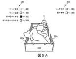
図5A及び図5Bによると、ビデオコンポーネントは、縦方向のベッド縁部201c、201dに対する患者の位置の段階的なインジケーター302をさらに提供する。その意味で、右側のベッド縁部201cに対する患者の位置を監視することは、図2における第1の関心領域202の右の縦縁部に対する最右部センターオブモーショングラビティー401の位置を監視することにより行われる。
5A and 5B, the video component further provides a
逆に、ビデオコンポーネントは、第1の関心領域202の左の縦縁部に対する最左部センターオブモーショングラビティー400の位置を監視することにより、左のベッド縁部201dに対する患者の位置を監視する。インジケーター302の値は、センターオブモーショングラビティー400、401のそれぞれが同じ側の第1の関心領域202の縦縁部からより遠いとき、緑色により近く、センターオブモーショングラビティー400、401がその同じ縁部により近いとき、赤色により近い。
Conversely, the video component monitors the position of the patient with respect to the
結果的に、図5Aは、患者2がベッド縁部201cに触れているので、オレンジ色でインジケーター302を示すのに対し、図5Bでは、患者2がベッド縁部201cを登っているか、又は、ベッド縁部201cの上にいるので、インジケーター302が赤色である。関与する異なる動きの混じり合いに起因して、同様に他のインジケーター300もそうした他のインジケーター300の色を変える。図5Aでは、患者2が依然としてベッド内200にいるので、「ベッド離床」インジケーター301が依然として緑色であるのに対し、患者2がベッド200を離れつつあるとき、図5Bにおいてそれぞれのインジケーター301がオレンジ色に変わる。ビデオデータリスクスコア110に対するインジケーター305もオレンジ色である。患者2の行動が多くの動きを伴うとき、落ち着きのない状態のインジケーター304が同様に緑色から離れる。
As a result, FIG. 5A shows the
さらに、ビデオコンポーネントは、水平センターオブモーショングラビティー(最右部及び最左部)400及び401の両方が第1の関心領域202の縦方向の境界内にあるとき、患者2が、例えば睡眠又は鎮静状態にある間、大きな動きをせずにベッド200内で安全であることを検出し得る。これは図7に示され、図7では、患者2が動いていないので、インジケーター300のそれぞれがすべて緑色である。
In addition, the video component allows the
図6A及び図6Bは、患者2がベッド内で安全であることが検出される、昼光及び夜間状態におけるビデオコンポーネントの実行を示す。この場合、インジケーター300は示されない。しかし、患者2を覆うブランケット上の点400及び401は、ベッド縁部201c、201dの領域内、すなわち、第1の関心領域202の縦方向の境界内において両方が観測される2つの水平センターオブモーショングラビティーを表す。
6A and 6B show the execution of the video component in daylight and night conditions when the
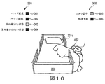
最左部センターオブモーショングラビティーが第1の関心領域202の右の縦縁部を越えた、及び、最右部センターオブモーショングラビティー401が第2の関心領域203bの右の縦縁部を越えたとき、ビデオコンポーネントは、患者2がベッド200を意図的に離床したことを検出する。図8及び図9に示されるように、前述の条件が満たされたとき、「ベッド離床」に対するインジケーター301が赤色になる。ここまでに既に詳細に説明されるように、この場合、ベッド200を離れることは、例えば胴を起こすこと、ベッド縁部201cに向かって動くこと、従って、さらにビデオデータリスクスコア110を大きくさせるきっかけとなることといった多くの動きを伴うので、他のインジケーター300が色を変える。
The leftmost center of motion gravity crossed the right vertical edge of the
ビデオコンポーネントは、最高部センターオブモーショングラビティー402が関心領域202の基部204及び関心領域203の基部205の下方に位置する特定の水平閾値未満に位置する場合、最左部センターオブモーショングラビティー400が第1の関心領域202の右の縦縁部を越えた、及び最右部センターオブモーショングラビティー401が第2の関心領域203bの右の縦縁部を越えたとき、患者2がベッド200の外に落ちたことを検出する。閾値は、多くのビデオにわたる学習を介して決定される。図10に示されるように、前述の条件が満たされたとき、「ベッド転落」に対するインジケーター306が赤色になる。患者2がこの時点でベッド200の外部で寝ているが、胴が下がっているので、他のインジケーター300が同様に関与して色を変化させ、「胴が起きた状態」のインジケーター303のみが緑色となる。
If the video component is located below a particular horizontal threshold where the top center of
全面的なベッド転落リスクを示すビデオデータリスクスコア(Video data risk score)110の計算は、転落検出を除く検出されたすべてのパラメータの線形結合又は和を、計算に関係する検出されたリスク因子の数(No_RF)で割ったものに基づく。図3から図10に示される例において、リスク因子の数は3であり(No_RF=3)、すなわち次式のとおりである。
Video data risk score=(Torso Up+Restless+Bed Edge)/No_RF
(ビデオデータリスクスコア=(胴が起きた状態+落ち着きのない状態+ベッド縁部)/No_RF)
The calculation of the video
Video data risk score = (Torso Up + Restless + Bed Edge) / No_RF
(Video data risk score = (state with torso + restless state + bed edge) / No_RF)
以下、バイタルサインセンサー13の機能が詳細に説明される。以下、ビデオコンポーネントと同様に、バイタルサインセンサー13及びそれぞれのバイタルサイン処理ユニット9は、「バイタルサインコンポーネント」と呼ばれる。処理ユニット9は、ここまでに図1を参照して説明されるように、患者の部屋40内のバイタルサインセンサー13から入力を受信する。
Hereinafter, the function of the
デバイス1のこの部分が、例えば脈拍計、血圧を監視するためのデバイスなどといった、患者の部屋40内に、又は患者の体に直接配置されたバイタルサインセンサー13から入力を受信する。代替的に、バイタルサインセンサー13は、遠隔センサー、例えば特定の皮膚エリアを照射することにより血中酸素含有量を監視し得るPPGセンサーであり得る。バイタルサインコンポーネントは、繰り返しになるがビデオコンポーネントと同様に2つの機能を兼ね備える。一方で、バイタルサイン又は生理学的信号(例えば心臓信号、呼吸信号、加速度計信号など)の信頼性が評価され、その一方で、システムがリスク因子の存在をリアルタイムで検出し、リスク因子の存在に基づいて、システムが、ベッド転落事故の可能性を示すリスクスコアを計算する。この機能は、上述のように生理学的信号の信頼性が十分であると判定された場合にのみ実行される。
This part of the
リアルタイムで検出される変更可能なリスク因子は、次のもの、すなわち、患者が緊張又はストレスを感じること、患者が不安を感じること、患者が落ち着きのない状態にあること、すなわち転げ回ること、及び向きを変えること、又は、患者が動揺を感じることであり、これらは強く又は速く大きな不規則な動きを介して表される。さらに、ベッド空間における患者の姿勢、すなわち、患者の胴が起きた状態であること、患者がベッド縁部から身を乗り出した状態であること、又は、患者がベッド外に到達した状態であることが検出され得る。 Mutable risk factors detected in real-time include: patient tension or stress, patient anxiety, patient restlessness, i.e. rolling around, and Turning or the patient feeling upset, which is manifested via strong or fast large irregular movements. In addition, the posture of the patient in the bed space, that is, the patient's torso is in a raised position, the patient leans out of the bed edge, or the patient has reached the outside of the bed. Can be detected.
上述の変更可能なリスク因子を検出することは、バイタルサインセンサー13からの入力に基づいて、ベッド転落事故に対するバイタルサインリスクスコア111を計算することを可能にする。以下のバイタルサインリスクスコア111は、R_VitalSignsと表記される。バイタルサインセンサーが信頼できない場合、システム11は、信号をまったく処理せず、信号の信頼性欠如に起因してリスクが評価されなかったことを示すために、R_VitalSignsが−1に設定される。
Detecting the modifiable risk factors described above allows calculating a vital
バイタルサインセンサーから受信された生理学的信号の信頼性の評価は、バイタルサインセンサー信頼性SR_VSを表す変数により行われる。センサー信頼性が十分であると評価されたとき、SR_VSが1に設定され、そうでないときは、0に設定される。 The evaluation of the reliability of the physiological signal received from the vital sign sensor is performed by the variable representing the vital sign sensor reliability SR_VS. SR_VS is set to 1 when the sensor reliability is evaluated to be sufficient, and is set to 0 otherwise.
評価は、信号ブロードキャスティングレートに、並びに、信号アーチファクトのレートに基づく。その意味で、信号ブロードキャスティングレートがシステム要件として規定された閾値(例えば1Hz)未満であるときは常に、バイタルサインセンサー13の信号が信頼できないと判定され、SR_VSが0に設定される。同様に、信号アーチファクトのレートが閾値を上回った場合、例えば、動く時間窓内における外れ値サンプルの割合が閾値より高い場合、すなわち、例えば、1分の窓内において10%を上回るサンプルが外れ値である場合、バイタルサインセンサー13の信号が信頼できないと判定され、SR_VSが0に設定される。
The evaluation is based on the signal broadcasting rate as well as the rate of signal artifacts. In that sense, whenever the signal broadcasting rate is less than the threshold (for example, 1 Hz) defined as the system requirement, it is determined that the signal of the
しかし、信号ブロードキャスティングレート並びに信号アーチファクトレートが上述の閾値に対して許容可能範囲内である場合、SR_VSが1に設定される。 However, if the signal broadcasting rate as well as the signal artifact rate is within the acceptable range for the above threshold, SR_VS is set to 1.
この生理学的信号の信頼性評価は、特定の頻度で、若しくは特定の間隔で時間通りに、又は、動く信号窓を使用して連続的に行われ得る。動く信号窓を使用して連続的に行うという選択肢は、評価される信号の小部分をバッファリングすることを意味し、プロセッサの性能を簡略化することに役立つ。 The reliability evaluation of this physiological signal may be performed at a specific frequency, at specific intervals in time, or continuously using a moving signal window. The option of using a moving signal window in succession means buffering a small part of the evaluated signal, which helps to simplify the performance of the processor.
以下、バイタルサインデータ140に基づくリスク因子の検出及びリスクスコアの計算が説明される。 Hereinafter, detection of risk factors and calculation of risk scores based on the vital sign data 140 will be described.
バイタルサインコンポーネントは、専用処理ユニット9において動作し、バイタルサインセンサー13から入力を受信し、その入力に基づいて、バイタルサインコンポーネントが、上述のようにベッド転落事故につながることが知られた多くのリスク因子をリアルタイムで検出する。本コンポーネントは、上述のリスク因子の検出を使用して、ベッド転落事故に対する可能性をリアルタイムで示すバイタルサインリスクスコアR_VitalSigns111を計算する。従って、それぞれの構成要素の出力は、SR_VS信号信頼性インジケーター及びR_VitalSignsリスクスコア111を含む。
The vital sign component operates in a dedicated processing unit 9 to receive input from the
患者2が何らかの緊張又はストレスを感じた場合、それぞれのリスク因子が、次の手法で、すなわち、システムが(例えば0.5分といった)閾値より長い時間窓内において、HR、RSP速度に対するベースライン平均に対するわずかに高い平均値の増加傾向(例えば5%未満の増加)を検出し、HRVに対するわずかに低い値を検出するが、システム11がACC信号において大幅な動きを検出しない手法で、心拍(HR)、心拍変動(HRV)、呼吸速度(RSP速度)、及び加速度計(ACC)信号を分析することにより検出される。加速度計は好ましくは、患者2の胸に配置されるが、体の他の適切な位置にも配置され得る。
If
患者2が不安を感じた場合、システムは、(例えば0.5分といった)閾値より長い時間窓内においてHR、RSP速度に対するベースライン平均に対する大幅に高い平均値の増加傾向(例えば5%より大きな増加)を、及び、HRVに対するより低い値を検出するが、システムは、ACC信号において大幅な動きを検出しない。
If
さらに、図11から図15を参照して説明されるように、ベッド200内における患者の姿勢が、それぞれのリスク因子を特定するために使用される。
Further, the patient's posture within the
患者2がベッド200内で上半身を起こしている場合、図11に示す「Torso up(胴が起きた状態)」信号が、x、y、z加速度計信号に次の式(1)、すなわち、
ここで、lcountsi(iはチャンネル番号x、y、zを表す)は、カットオフ=1Hzとして低域通過フィルタ処理された加速度計カウントであり、cmingi=加速度−gに対するlcounts、cplusgi=加速度+gに対するlcountsである。 Here, lcounts i (i represents the channel number x, y, and z) is a low-pass filtered accelerometer counts as a cutoff = 1Hz, lcounts for cming i = acceleration -g, cplusg i = Lcounts for acceleration + g.
前述の式は、加速度計カウント「lcounts」の正規化のために使用されて、(重力加速度が負の座標方向を指す場合の)「−1」から(重力加速度が正の座標方向を指す場合の)「+1」の範囲に正規化された値「tn」を導く。「+x」方向は、患者の胸から患者の左側に向かう方向を指し示し、「−x」方向は、患者の右側に向かう方向を指し示す。「+y」方向は、患者の頭部に向かう方向を指し示し、「−y」方向は、患者の足に向かう方向を指し示す。「+z」方向は、胸から外に向かう方向を指し示す、「−z」方向は、患者の胸から患者の背中に向かう方向を指し示す。例:休んでいる患者の正規化された加速度計読み取り値(0;0;−1)は、「仰向け」の位置を示すのに対し、読み取り値(0;−1;0)は、「胴が起きた状態」の位置を示す。 The above equation is used for normalization of the accelerometer count "lcounts", from "-1" (when gravity acceleration points in the negative coordinate direction) (when gravity acceleration points in the positive coordinate direction). ), Which leads to the normalized value "tn" in the range "+1". The "+ x" direction refers to the direction from the patient's chest to the left side of the patient, and the "-x" direction refers to the direction to the right side of the patient. The "+ y" direction points towards the patient's head and the "-y" direction points towards the patient's foot. The "+ z" direction points out from the chest and the "-z" direction points out from the patient's chest toward the patient's back. Example: The normalized accelerometer reading (0; 0; -1) of a resting patient indicates a "supine" position, while the reading (0; -1; 0) indicates "torso." Shows the position of the "state where" has occurred.
図11に示されるように、Torso Up(胴が起きた状態)信号が0.7より大きなピーク値に達したとき、システム11は、患者2が患者2の胴を起こしたことを検出する。図11における左下部分の丸印は、図11の残りの3つの部分において3つの軸に沿って示される、現在の「胴が起きた状態」の状況を示す。
As shown in FIG. 11, when the Torso Up signal reaches a peak value greater than 0.7, the
患者がベッドの外に到達した状態である場合、図12に示す「Reach out(外に到達した状態)」信号が、x、y、z加速度計信号に式(2)、つまり、
Reach out=|sin(2ψ)|・(tnz>0)・sin(2φ)・(tny<0) (2)
(外に到達した状態=|sin(2ψ)|・(tnz>0)・sin(2φ)・(tny<0) (2))
並びに、
Reach out = | sin (2ψ) | · (tn z> 0) · sin (2φ) · (tn y <0) (2)
(States reached out = | sin (2ψ) | · (tn z> 0) · sin (2φ) · (tn y <0) (2))
And
従って、「Reach out」における第1の因数(=|sin(2Ψ)|*(tz>0))は、Ψ=45度であってtz>0の場合に最大(=1)となる。「Reach out」における第2の因子(=sin(2φ)*(ty<0))は、φ=45度であってty<0の場合に最大(=1)となる。 Therefore, the first factor (= | sin (2Ψ) | * (t z > 0)) in “Reach out” becomes maximum (= 1) when Ψ = 45 degrees and t z > 0. .. The second factor in the "Reach out" (= sin (2φ) * ( t y <0)) is maximized (= 1) in the case of t y <0 a phi = 45 degrees.
図12に示されるように、Reach out信号が0.8より大きなピーク値に達したとき、システム11は、患者2が外に到達した状態であることを検出する。図12における左下部分の丸印は、図12の残りの3つの部分において3つの軸に沿って示される現在の「外に到達した状態(reach out)」の状況を示す。
As shown in FIG. 12, when the Reach out signal reaches a peak value greater than 0.8, the
患者2がベッド縁部201から身を乗り出した状態である場合、図13に示す「Lean over(身を乗り出した状態)」信号が、x、y、z加速度計信号に式(3)、すなわち、
Lean over=|sin(2ψ)|・(tnz>0)・−sin(2φ)・(tny>0) (3)
(身を乗り出した状態=|sin(2ψ)|・(tnz>0)・−sin(2φ)・(tny>0) (3))
並びに、
Lean over = | sin (2ψ) | · (tn z> 0) · -sin (2φ) · (tn y> 0) (3)
(A state in which leaned = | sin (2ψ) | · (tn z> 0) · -sin (2φ) · (tn y> 0) (3))
And
従って、「Lean over」における第1の因数(=|sin(2Ψ)|*(tz>0))は、Ψ=45度であってtz>0である場合、最大(=1)となる。「Lean over」における第2の因子(=−sin(2φ)*(ty>0))は、φ=−45度であってty>0である場合、最大(=1)となる。 Therefore, the first factor (= | sin (2Ψ) | * (t z > 0)) in “Lean over” is the maximum (= 1) when Ψ = 45 degrees and t z > 0. Become. The second factor in the "Lean-over-'(= -sin (2φ) * ( t y> 0)) , optionally in a phi = -45 ° is t y> 0, the maximum (= 1).
図13に示されるように、Lean Over信号が0.5より大きなピーク値に達した場合、システム11は、患者2が身を乗り出した状態であることを検出する。図13における左下部分の丸印は、図13の残りの3つの部分において3つの軸に沿って示される現在の「身を乗り出した状態」の状況を示す。
As shown in FIG. 13, when the Lean Over signal reaches a peak value greater than 0.5, the
落ち着きのない状態は、患者の胴が水平に配向されて、体の転げ回る動き、及び向きを変える動きに注目したとき、動きの広がりが限られ、x軸及びz軸において支配的となる運動として規定される。患者2が落ち着きのない状態にあるとき、図14に示される「restlessness(落ち着きのない状態)」信号がx、y、z加速度計信号に式(4)、すなわち、
Restlessness=movav(50・rm,5s) (4)
(落ち着きのない状態=movav(50・rm,5s) (4))
及び、
Restlessness = movav (50 ・ rm, 5s) (4)
(A restless state = movav (50 rm, 5s) (4))
as well as,
量「rni」は、各座標方向iに対する、正規化された高域通過フィルタ処理された加速度計信号である。次に、個々の成分rniにより与えられたベクトルの大きさ、すなわち、患者2の急速に変動する加速度を示す量が計算される。しかし、患者2は、歩行、走行、又は跳躍などの「通常の」行動も実施し得る。これらの「通常の」行動のすべてが、1に近い「TorsoUp」信号を特徴とするのに対し、ベッド内で寝ている患者の「restlessness」は、0に近い「TorsoUp」信号を特徴とする。従って、「rm」の定義は、「restlessness」の計算において、言及される「通常の」行動を抑制する因子「(1−TorsoUp)」を含む。落ち着きのない状態の段階中、信号「rm」が0とその最大値との間で急速に振動するので、最終的に、「Restlessness」信号を取得するために、「移動平均」の演算「movav」、すなわち、直近の5sにわたって(任意の因数50により乗算された)信号「rm」を平均化することが実施される。
The quantity "rni" is the normalized high pass filtered accelerometer signal for each coordinate direction i. Next, the magnitude of the vector given by the individual components rni, ie the quantity indicative of the rapidly varying acceleration of the
図14において、落ち着きのない状態は、x、y、z加速度計信号に式(1)を適用することにより取得された信号を介して表される。 In FIG. 14, the restless state is represented via the signal obtained by applying equation (1) to the x, y, z accelerometer signal.
患者の動揺は、患者の胴が縦方向に配向されて、動きの広がりが高く、特に、図14に示す落ち着きのない状態の場合より大幅に高く、さらに、y軸及びx軸において支配的である運動として規定される。動揺は、強く/速く大きな不規則な動きを介して表される。 The patient's wobble is significantly higher than in the restless state shown in FIG. 14, with the patient's torso oriented longitudinally, and the movement is high, and is also dominant in the y and x axes. Specified as a movement. Upset is manifested via strong / fast and large irregular movements.
これは、次の式(5)、すなわち、
Agitation=movav(50・rm,5s) (5)
(動揺=movav(50・rm,5s) (5))
によりモデル化され、ここで、
Agitation = movav (50 ・ rm, 5s) (5)
(Agitation = movav (50 ・ rm, 5s) (5))
Modeled by
図15において、restlessness(落ち着きのない状態)信号とagitation(動揺)信号とが組み合わされた図は、落ち着きのない状態の場合(図15における上のグラフ)より、動揺時の動きの広がりが大幅に高いことを示す。 In FIG. 15, a diagram in which the restlessness signal and the aggregation signal are combined shows that the spread of the movement during shaking is significantly larger than that in the case of the restless state (the upper graph in FIG. 15). Is high.
R_VitalSignsリスクスコア111の計算は、上述のリスク因子を評価することに基づいており、この場合において、R_VitalSignsは−各リスク因子に関係して−パラメータxi(i=1..8)だけ増やされる。これは、次の試験及び関係する演算を意味する。
しかし、リスクスコアを結び付ける他の可能性が存在する。実際の式は、データから、すなわち単一のパラメータの異なる発生状況から学習される。 However, there are other possibilities for linking risk scores. The actual equations are learned from the data, i.e. from different occurrences of a single parameter.
システムの初期化時に、パラメータx1からx7が、文献調査により示される値に基づいて、初期化され得るのに対し、経時的に、システム11が手近にある特定の集団に対するベッド転落の発生に対する上述の各リスク因子の影響を学習することにより、パラメータ値を調節する。これは、ベッド転落事象の可能性に対する各リスク因子の影響を理解するため、及び、上述のパラメータの値を更新するために、相関分析を実行すること、及び、各ベッド転落事故後に回帰法を適用することにより行われる。従って、時間が経過するにつれて、システム11は、リスクスコアを特定することが益々正確になる。ベッド転落事故が発生しなかった場合、パラメータ調節は必要とされない。
At system initialization, the parameters x1 to x7 can be initialized based on the values shown by literature surveys, whereas over time the
以下、介入ユニット15がより詳細に説明される。介入ユニット15は、好ましくは、医療スタッフによる、及び同様に保守スタッフによるアクセスを可能にするために、並びに同時に多くの個人を監視することを可能にするために、患者の部屋40から離れたワークステーションルーム50内に位置する。介入ユニット15が、分類ユニット10からの患者プロファイルと、計算ユニット6からの上述の総リスクスコア114とを入力として受信する。
In the following, the
それらの値(例えば総リスクスコア114が閾値を上回っているか、又は短い時間窓内で大幅に増加しつつある)に基づいて、介入ユニット15が次のアクションのうちの1つ又は複数を実施する。
Based on those values (eg, the
医療スタッフが患者の要求に応じて介護に向かう途中で、介入ユニット15が、患者の部屋40内のフィードバックユニット14を介して患者と連絡を取り、状況を評価し、必要な場合は患者2を落ち着かせることを試み、及び、ベッド200内に留まるように患者2を説得する。
The
代替的に、又は同時に、介入ユニットは、最も近くて対応可能な医療スタッフを識別し、そのスタッフメンバーに上述の情報を送信して迅速な行動を確実なものとする。患者の部屋40に最も近いスタッフを識別するために、介入ユニット15は、測位技術(例えばGPS)を使用し得る。その時点で対応可能なスタッフを識別するために、介入ユニット15は、その時点でのスタッフの対応可能性を示した、データベースに記憶されたスタッフのスケジュール17を参照する。
Alternatively, or at the same time, the intervention unit identifies the closest available medical staff and sends the above-mentioned information to its staff members to ensure prompt action. To identify the staff closest to the patient's
介入ユニット15は、任意の例において、医療スタッフに、必要とされる介入と共にベッド転落事故に対するリスクを示す警報コードをエンドする。
The
患者プロファイルに関係した詳細を示す介入情報、及び、この特定の患者により与えられたプロファイルに対して推奨される介入も、介入ユニット15により送信される。
Intervention information indicating details related to the patient profile and recommended interventions for the profile given by this particular patient are also transmitted by the
加えて、介入ユニット15は、中の時間枠に関係した医療スタッフに、効果的であるように、及び事故を防止するために、介入が提供される必要があることを知らせる。
In addition, the
さらに、介入ユニット15は、他の予測される行動を上回るように、現在の患者の要求を優先順位付けすることに役立つ。
In addition, the
介入ユニット15は、図1において説明される、患者監視、ベッド転落リスク評価、プロファイルに基づく患者分類、及び適応型の介入を担うより大きなインフラの一部である。
The
介入ユニット15は、例えば必要に応じた患者2との直接的な対話のための音声認識を利用した、人工知能の実施態様を使用する。システムは、この背景に関連した次の3つの状況を区別する。
1.総リスクスコア114は、低いか、又は中程度(特定の閾値未満)であるが、限られた時間窓内で低速から中程度の速度で増加する−例えば、リスクスコア値は、直前の10分間に最大10度の角度の平均傾き(平均傾き<=0.17)のもとで上昇する。
2.総リスクスコア114は、低いか、又は中程度(特定の閾値未満)であるが、限られた時間窓(例えば5〜10分)内で大幅に増加する−例えばリスクスコア値が10度より大きな角度の平均傾き(平均傾き>0.17)のもとで上昇する。
3.総リスクスコア114が、高い(特定の閾値を上回る)と特定される。
The
1. The
2. The
3. A
介入ユニット15は、上述の各状況において、患者プロファイルに由来する情報に基づいて応答する。その意味で、システムは、認知能力レベル(CgAL)、対話能力レベル(CmAL)及び遵守性レベル(CL)の観点から患者2を分類する。患者プロファイルに基づいて、患者が認知障害をもたない、及び、発話障害がない場合、CgALが高い(High)と設定される。任意の他の状況において、CgALが低い(Low)に設定される。加えて、患者プロファイル(特に心理遵守性プロファイル)に基づいて、システムが、CLを高い(High)又は低い(Low)に設定する。
The
次の表において状況が説明され、この状況により、介入ユニット15が総リスクスコア114の値の傾向に応答する。
The situation is described in the following table, which causes the
1.総リスクスコア114が低いか、又は中程度(特定の閾値未満)であるが、限られた時間窓(例えば10分)内に低速から中程度の速度で増加する場合、介入ユニット15は、現在のリスクスコアの上昇に基づいて、効果的な防止のために利用可能な時間枠を看護師に示すために、総リスクスコア114が高くなるまでどれくらいの時間があるか予測を行う。これは、介護を必要とする患者を優先順位付けすることに役立つ。
1. If the
2.総リスクスコア114が、低いか、又は中程度(特定の閾値未満)であるが、限られた時間窓(例えば5〜10分)内において大幅に増加する場合、介入ユニット15は、効果的な予防介入のために利用可能な時間枠を、勤務中の看護師又は最も近くて対応可能な医療スタッフに示すために、現在のリスクスコアの上昇に基づいて、総リスクスコア114が高くなるまでどれくらいの時間があるか再度予測を行う。これは、介護を必要とする患者2を優先順位付けすることに役立つ。
2. If the
介入マトリックスは、表1に記述されたものと同様であるが、この場合、患者が勤務中の看護師に対して自動的に最高優先度を与えられ、勤務中のすべての看護師が他の患者2に割り当てられており、介護することができない場合、最も近くて対応可能な医療スタッフが連絡を受けるという点で違いがある。
The intervention matrix is similar to that described in Table 1, but in this case the patient is automatically given the highest priority to the nurses on duty and all nurses on duty are The difference is that if assigned to
3.総リスクスコア114が高い(特定の閾値を上回る)と特定された場合、前述の状況に関して違いが生まれる。行動がすぐに必要とされる。介入ユニット15は、単に最も近くて対応可能な医療スタッフを識別し、同様に勤務中の看護師にも患者が介護される必要があることを知らせる。
3. If the
前述のように、フィードバックユニット14(表1及び表2において「音声による対話」と呼ばれる)は、現在病室において通常利用可能なTV受像機であり得る。しかし、環境が例えば認知障害者のための療養施設である場合、フィードバックユニットが、スピーカーを含むディスプレイ、マイクロホン、及び患者2付近の適切な位置に配置されたさらなる対話の手段であり得る。
As mentioned above, the feedback unit 14 (referred to in Tables 1 and 2 as "voice interaction") may be a TV receiver normally available in the hospital room at present. However, if the environment is a care facility for the cognitively impaired, for example, the feedback unit may be a display including a speaker, a microphone, and a means of further interaction arranged in a suitable position near the
図面及び上述の説明において本発明が詳細に例示及び説明されるが、このような例示及び説明は例示又は一例とみなされ、限定とはみなされず、本発明は、開示される実施形態に限定されない。開示される実施形態に対する他の変形例が、図面、本開示、及び付属の特許請求の範囲の考察により、請求項に記載された発明を実施する当業者により理解及び実現され得る。 While the invention is illustrated and described in detail in the drawings and foregoing description, such illustration and description are to be considered illustrative or exemplary and not restrictive, and the invention is not limited to the disclosed embodiments. .. Other variations to the disclosed embodiments can be understood and effected by a person skilled in the art in practicing the claimed invention, from a study of the drawings, the disclosure, and the appended claims.
特許請求の範囲において、「備える」という用語は、他の要素もステップも排除せず、「1つ(a)」又は「1つ(an)」という単数表現の不定冠詞は、複数を排除しない。単一の要素又は他のユニットが、特許請求の範囲に記載されるいくつかの項目の機能を実現してもよい。単に、特定の手段が相互に異なる従属請求項に記載されているという事実は、利点を得るためにこれらの手段の組み合わせが使用不可能なことを示すわけではない。 In the claims, the term "comprising" does not exclude other elements or steps, and the singular indefinite article "a" or "an" does not exclude a plurality. .. A single element or other unit may fulfill the functions of several items recited in the claims. The mere fact that certain measures are recited in mutually different dependent claims does not indicate that a combination of these measures cannot be used to advantage.
コンピュータプログラムは、他のハードウェアと一体的に、又は他のハードウェアの一部として供給される、光記憶媒体又はソリッドステート媒体などの適切な媒体に記憶/分散されてもよいが、例えばインターネット又は他の有線若しくは無線電気通信システムを介して、他の形態でも分散されてもよい。 The computer program may be stored / distributed in a suitable medium such as an optical storage medium or a solid state medium, which is supplied integrally with other hardware or as a part of the other hardware, but is, for example, the Internet Alternatively, it may be distributed in other forms, via other wired or wireless telecommunication systems.
特許請求の範囲における参照符号は、いずれも特許請求の範囲を限定するように解釈されてはならない。 Any reference signs in the claims shall not be construed as limiting the scope of the claims.
Claims (15)
前記デバイスが、
前記個人の個人データと前記個人の総リスクスコアとを取得するための第1のポートと、
取得された前記データに基づいて前記個人の切迫したベッド転落に関係した予測と前記個人の前記ベッド転落を防止するための介入のための時間枠とを特定するための介入ユニットと、
前記予測と取得された前記データとに基づいて介入信号を出力するための第2のポートと、
を備え、
前記介入ユニットが、前記総リスクスコア、並びに、所定の時間枠内における前記総リスクスコアの変化及び/又は推移に基づいて、前記総リスクスコアが所定の閾値を上回るまでの時間を予測する、デバイス。 A device for adaptive intervention with respect to an individual in relation to an individual's risk of falling a bed, comprising:
The device is
A first port for obtaining personal data of the individual and a total risk score of the individual;
An intervention unit for identifying a prediction related to the imminent bed fall of the individual based on the acquired data and a time frame for intervention of the individual to prevent the bed fall;
A second port for outputting an intervention signal based on the prediction and the acquired data;
Equipped with
The intervention unit, the total risk score, and, based on the change and / or changes in the total risk score at a given time frame, the total risk score that predict the time until above a predetermined threshold, device.
請求項1に記載のデバイス。 The intervention unit outputs the intervention signal directly to the individual by means of an interface arranged in the vicinity of the individual,
The device of claim 1.
請求項1に記載のデバイス。 Further comprising a third port for obtaining data relating to staff schedules,
The device of claim 1.
請求項3に記載のデバイス。 The intervention unit outputs the intervention signal to a staff member and initiates staff intervention for the individual based on the staff schedule, the acquired data and the prediction.
The device according to claim 3.
請求項1に記載のデバイス。 The personal data of the individual includes one or more of age, sex, neurological symptoms, symptoms, disability, medication, fall history, psychological profile,
The device of claim 1.
請求項1に記載のデバイス。 The total risk score is obtained by obtaining the personal data of the individual and by obtaining sensor data from at least one sensor located in the vicinity of the individual and / or in contact with the individual Identified,
The device of claim 1.
請求項1に記載のデバイス。 The intervention unit classifies the individual ability level of the individual based on the individual data of the individual, and the ability level of the individual includes a cognitive ability level, an interactive ability level, and a compliance level.
The device of claim 1.
請求項7に記載のデバイス。 The cognitive performance level is related to the total risk score, wherein the total risk score is less than a predetermined threshold but increases under a slope of a predetermined average slope or less within a limited time window,
The device of claim 7.
請求項7に記載のデバイス。 The dialogue ability level is related to the total risk score, which increases under a slope where the total risk score is less than a predetermined threshold but exceeds a predetermined average slope within a limited time window,
The device of claim 7.
請求項7に記載のデバイス。 The compliance level is related to the total risk score identified above a predetermined threshold ,
The device of claim 7.
前記システムが、
前記個人の個人データを提供するための分類ユニットと、
前記個人の総リスクスコアを計算するための計算ユニットと、
前記分類ユニット及び前記計算ユニットの出力に基づく、前記個人に対する適応型の介入のための請求項1から請求項10のいずれか一項に記載のデバイスと、
を備える、システム。 A system for adaptive intervention for an individual in relation to an individual's risk of falling a bed, comprising:
The system is
A classification unit for providing personal data of said individual,
A calculation unit for calculating the total risk score of the individual,
Device according to any one of claims 1 to 10 for adaptive intervention on the individual based on the outputs of the classification unit and the calculation unit,
A system comprising:
前記個人の個人データを取得するステップと、
前記個人の総リスクスコアを取得するステップと、
取得された前記データに基づいて前記個人の切迫したベッド転落に関係した予測と前記個人の前記ベッド転落を防止するための介入のための時間枠とを特定するステップと、
取得された前記データと前記予測とに基づいて前記個人に介入するステップと、
を有し、
前記特定するステップが、前記総リスクスコア、並びに、所定の時間枠内における前記総リスクスコアの変化及び/又は推移に基づいて、前記総リスクスコアが所定の閾値を上回るまでの時間を予測するステップを有する、方法。 A method for identifying an individual's risk of falling a bed, said method comprising:
Obtaining personal data of the individual,
Obtaining a total risk score for the individual,
Identifying a prediction related to the imminent bed fall of the individual based on the acquired data and a time frame for intervention of the individual to prevent the bed fall.
Intervening with the individual based on the acquired data and the predictions;
Have a,
Predicting the time until the total risk score exceeds a predetermined threshold based on the total risk score and the change and / or transition of the total risk score within a predetermined time frame to have a method.
請求項12に記載の方法。 Interacting with the individual includes responding directly to the individual via an interface and / or initiating staff intervention based on a staff schedule, the acquired data and the predictions. ,
The method according to claim 12.
最も近くて対応可能なスタッフメンバーを識別するステップと、
前記スタッフメンバーに警報コードを送信するステップと、
ベッド転落事故を防止するために利用可能な時間枠について前記スタッフメンバーに知らせるステップと、
前記個人の患者プロファイルの詳細について前記スタッフに知らせるステップと、
推奨される介入行動について前記スタッフに知らせるステップと、
前記スタッフメンバーの他のタスクとの関係において前記介入を優先順位付けするステップと、
のうちの1つ又は複数を有する、
請求項13に記載の方法。 The step of initiating the staff intervention includes:
Identifying the closest available staff member,
Sending an alert code to the staff member,
Informing the staff member of the time frame available to prevent a bed fall accident;
Informing the staff about details of the individual's patient profile;
Informing the staff about recommended intervention behavior,
Prioritizing the intervention in relation to other tasks of the staff member;
Having one or more of,
The method of claim 13 .
コンピュータプログラム。 13. Program code means for causing a computer to perform the steps of the method of claim 12,
Computer program.
Applications Claiming Priority (3)
| Application Number | Priority Date | Filing Date | Title |
|---|---|---|---|
| EP16185507 | 2016-08-24 | ||
| EP16185507.7 | 2016-08-24 | ||
| PCT/EP2017/071320 WO2018037073A1 (en) | 2016-08-24 | 2017-08-24 | Device, system and method for patient monitoring to predict and prevent bed falls |
Publications (2)
| Publication Number | Publication Date |
|---|---|
| JP2019534495A JP2019534495A (en) | 2019-11-28 |
| JP6692987B2 true JP6692987B2 (en) | 2020-05-13 |
Family
ID=56802306
Family Applications (1)
| Application Number | Title | Priority Date | Filing Date |
|---|---|---|---|
| JP2019510665A Expired - Fee Related JP6692987B2 (en) | 2016-08-24 | 2017-08-24 | Devices, Systems, and Methods for Patient Monitoring to Predict and Prevent Bed Fall |
Country Status (5)
| Country | Link |
|---|---|
| US (1) | US20190221315A1 (en) |
| EP (1) | EP3504649B1 (en) |
| JP (1) | JP6692987B2 (en) |
| CN (1) | CN109643585A (en) |
| WO (1) | WO2018037073A1 (en) |
Families Citing this family (7)
| Publication number | Priority date | Publication date | Assignee | Title |
|---|---|---|---|---|
| US11699528B2 (en) | 2019-06-28 | 2023-07-11 | Hill-Rom Services, Inc. | Falls risk management |
| US20210358202A1 (en) * | 2020-05-13 | 2021-11-18 | Electronic Caregiver, Inc. | Room Labeling Drawing Interface for Activity Tracking and Detection |
| JP7466865B2 (en) | 2020-08-07 | 2024-04-15 | 公立大学法人名古屋市立大学 | Self-removal occurrence prediction device, self-removal occurrence prediction method, program, fall occurrence prediction device, fall occurrence prediction method, and medical safety improvement support method |
| US20220084383A1 (en) * | 2020-09-14 | 2022-03-17 | Curbell Medical Products, Inc. | System and method for monitoring an individual using lidar |
| CN112669566B (en) * | 2020-12-16 | 2022-09-02 | 问境科技(上海)有限公司 | Nursing early warning method and system based on human body posture analysis |
| CN112907894B (en) * | 2021-03-02 | 2022-12-02 | 深圳市医创加科技有限公司 | Falling-bed early warning method and system based on patient action prejudgment |
| WO2024138431A1 (en) * | 2022-12-28 | 2024-07-04 | 深圳迈瑞生物医疗电子股份有限公司 | Monitoring and prompting method, device and system |
Family Cites Families (9)
| Publication number | Priority date | Publication date | Assignee | Title |
|---|---|---|---|---|
| JP2005128967A (en) * | 2003-10-27 | 2005-05-19 | Sozo Gijutsu Kenkyusho:Kk | Medical device, method and program for detecting movement and computer readable recording medium |
| US20080281638A1 (en) * | 2007-05-07 | 2008-11-13 | Your Choice Living, Inc. | Method and apparatus for tracking, documenting, and predicting fall-related activities |
| JP2009005849A (en) * | 2007-06-27 | 2009-01-15 | Nippon Telegr & Teleph Corp <Ntt> | Apparatus for preventing turning over and falling down |
| WO2013150523A1 (en) | 2012-04-01 | 2013-10-10 | Earlysense Ltd. | Monitoring, predicting and treating clinical episodes |
| US9934427B2 (en) * | 2010-09-23 | 2018-04-03 | Stryker Corporation | Video monitoring system |
| JP6211891B2 (en) * | 2013-04-08 | 2017-10-11 | 日本電子工学株式会社 | Caregiver monitoring system |
| EP3323342B1 (en) * | 2013-11-15 | 2020-11-11 | Leaf Healthcare, Inc. | Prevention and treatment of bed exits, falls, and other conditions |
| JP6468510B2 (en) * | 2013-12-06 | 2019-02-13 | 国立大学法人宇都宮大学 | Patient status determination system |
| CN104484977B (en) * | 2014-11-21 | 2017-01-11 | 深圳市前海安测信息技术有限公司 | Wearable human body multidimensional tumbling prevention and detection device and detection method thereof |
-
2017
- 2017-08-24 WO PCT/EP2017/071320 patent/WO2018037073A1/en unknown
- 2017-08-24 EP EP17761458.3A patent/EP3504649B1/en active Active
- 2017-08-24 CN CN201780051539.1A patent/CN109643585A/en active Pending
- 2017-08-24 US US16/327,069 patent/US20190221315A1/en not_active Abandoned
- 2017-08-24 JP JP2019510665A patent/JP6692987B2/en not_active Expired - Fee Related
Also Published As
| Publication number | Publication date |
|---|---|
| EP3504649B1 (en) | 2020-05-13 |
| CN109643585A (en) | 2019-04-16 |
| US20190221315A1 (en) | 2019-07-18 |
| JP2019534495A (en) | 2019-11-28 |
| WO2018037073A1 (en) | 2018-03-01 |
| EP3504649A1 (en) | 2019-07-03 |
Similar Documents
| Publication | Publication Date | Title |
|---|---|---|
| JP6823160B2 (en) | Devices, systems, and methods for patient monitoring to predict and prevent bed falls | |
| JP6692987B2 (en) | Devices, Systems, and Methods for Patient Monitoring to Predict and Prevent Bed Fall | |
| JP2019537082A (en) | Devices, systems and methods for patient monitoring to predict and prevent bed falling | |
| US20200311609A1 (en) | Adaptive model-based system to automatically quantify fall risk | |
| US11129549B2 (en) | Device, system and method for patient monitoring to predict and prevent bed falls | |
| US20230222887A1 (en) | Machine learning based monitoring system | |
| US20180177436A1 (en) | System and method for remote monitoring for elderly fall prediction, detection, and prevention | |
| JP6588978B2 (en) | Apparatus, system and method for automatic detection of human orientation and / or position | |
| AU2024203613A1 (en) | System for recording, analyzing risk(s) of accident(s) or need of assistance and providing real-time warning(s) based on continuous sensor signals | |
| Bauer et al. | Modeling bed exit likelihood in a camera-based automated video monitoring application | |
| JP7314939B2 (en) | Image recognition program, image recognition device, learning program, and learning device | |
| Ianculescu et al. | Improving the Elderly’s Fall Management through Innovative Personalized Remote Monitoring Solution | |
| US20230187062A1 (en) | Method and system for assessment and predicting sleepiness during osa screening using consumer devices | |
| Huynh | Developing Wearable Sensor System for Elderly Independent Living Assessment | |
| Ranjan et al. | Human Context Sensing in Smart Cities | |
| Jimison et al. | Real-time measures of context to improve fall-detection models | |
| Isaza | A Fall Prevention System for the Elderly and Visually Impaired | |
| WO2021074102A1 (en) | System and method for detection of intermittent claudication in remote sensor data | |
| Hata et al. | A Health Care Service to Disaster Survivors |
Legal Events
| Date | Code | Title | Description |
|---|---|---|---|
| A621 | Written request for application examination |
Free format text: JAPANESE INTERMEDIATE CODE: A621 Effective date: 20190221 |
|
| A871 | Explanation of circumstances concerning accelerated examination |
Free format text: JAPANESE INTERMEDIATE CODE: A871 Effective date: 20190221 |
|
| A975 | Report on accelerated examination |
Free format text: JAPANESE INTERMEDIATE CODE: A971005 Effective date: 20190704 |
|
| A131 | Notification of reasons for refusal |
Free format text: JAPANESE INTERMEDIATE CODE: A131 Effective date: 20191007 |
|
| A521 | Request for written amendment filed |
Free format text: JAPANESE INTERMEDIATE CODE: A523 Effective date: 20191225 |
|
| TRDD | Decision of grant or rejection written | ||
| A01 | Written decision to grant a patent or to grant a registration (utility model) |
Free format text: JAPANESE INTERMEDIATE CODE: A01 Effective date: 20200317 |
|
| A61 | First payment of annual fees (during grant procedure) |
Free format text: JAPANESE INTERMEDIATE CODE: A61 Effective date: 20200415 |
|
| R150 | Certificate of patent or registration of utility model |
Ref document number: 6692987 Country of ref document: JP Free format text: JAPANESE INTERMEDIATE CODE: R150 |
|
| LAPS | Cancellation because of no payment of annual fees |