JP6692829B2 - Adhesion of textiles to equipment - Google Patents
Adhesion of textiles to equipment Download PDFInfo
- Publication number
- JP6692829B2 JP6692829B2 JP2017552792A JP2017552792A JP6692829B2 JP 6692829 B2 JP6692829 B2 JP 6692829B2 JP 2017552792 A JP2017552792 A JP 2017552792A JP 2017552792 A JP2017552792 A JP 2017552792A JP 6692829 B2 JP6692829 B2 JP 6692829B2
- Authority
- JP
- Japan
- Prior art keywords
- adhesive
- fabric layer
- zone
- input device
- adhesive zone
- Prior art date
- Legal status (The legal status is an assumption and is not a legal conclusion. Google has not performed a legal analysis and makes no representation as to the accuracy of the status listed.)
- Active
Links
Images


Classifications
-
- G—PHYSICS
- G06—COMPUTING OR CALCULATING; COUNTING
- G06F—ELECTRIC DIGITAL DATA PROCESSING
- G06F1/00—Details not covered by groups G06F3/00 - G06F13/00 and G06F21/00
- G06F1/16—Constructional details or arrangements
- G06F1/1613—Constructional details or arrangements for portable computers
- G06F1/1633—Constructional details or arrangements of portable computers not specific to the type of enclosures covered by groups G06F1/1615 - G06F1/1626
- G06F1/1675—Miscellaneous details related to the relative movement between the different enclosures or enclosure parts
- G06F1/1681—Details related solely to hinges
-
- B—PERFORMING OPERATIONS; TRANSPORTING
- B32—LAYERED PRODUCTS
- B32B—LAYERED PRODUCTS, i.e. PRODUCTS BUILT-UP OF STRATA OF FLAT OR NON-FLAT, e.g. CELLULAR OR HONEYCOMB, FORM
- B32B5/00—Layered products characterised by the non- homogeneity or physical structure, i.e. comprising a fibrous, filamentary, particulate or foam layer; Layered products characterised by having a layer differing constitutionally or physically in different parts
- B32B5/02—Layered products characterised by the non- homogeneity or physical structure, i.e. comprising a fibrous, filamentary, particulate or foam layer; Layered products characterised by having a layer differing constitutionally or physically in different parts characterised by structural features of a fibrous or filamentary layer
-
- B—PERFORMING OPERATIONS; TRANSPORTING
- B32—LAYERED PRODUCTS
- B32B—LAYERED PRODUCTS, i.e. PRODUCTS BUILT-UP OF STRATA OF FLAT OR NON-FLAT, e.g. CELLULAR OR HONEYCOMB, FORM
- B32B7/00—Layered products characterised by the relation between layers; Layered products characterised by the relative orientation of features between layers, or by the relative values of a measurable parameter between layers, i.e. products comprising layers having different physical, chemical or physicochemical properties; Layered products characterised by the interconnection of layers
- B32B7/04—Interconnection of layers
- B32B7/12—Interconnection of layers using interposed adhesives or interposed materials with bonding properties
- B32B7/14—Interconnection of layers using interposed adhesives or interposed materials with bonding properties applied in spaced arrangements, e.g. in stripes
-
- G—PHYSICS
- G06—COMPUTING OR CALCULATING; COUNTING
- G06F—ELECTRIC DIGITAL DATA PROCESSING
- G06F1/00—Details not covered by groups G06F3/00 - G06F13/00 and G06F21/00
- G06F1/16—Constructional details or arrangements
- G06F1/1613—Constructional details or arrangements for portable computers
- G06F1/1633—Constructional details or arrangements of portable computers not specific to the type of enclosures covered by groups G06F1/1615 - G06F1/1626
- G06F1/1662—Details related to the integrated keyboard
-
- G—PHYSICS
- G06—COMPUTING OR CALCULATING; COUNTING
- G06F—ELECTRIC DIGITAL DATA PROCESSING
- G06F3/00—Input arrangements for transferring data to be processed into a form capable of being handled by the computer; Output arrangements for transferring data from processing unit to output unit, e.g. interface arrangements
- G06F3/01—Input arrangements or combined input and output arrangements for interaction between user and computer
- G06F3/02—Input arrangements using manually operated switches, e.g. using keyboards or dials
- G06F3/0202—Constructional details or processes of manufacture of the input device
-
- B—PERFORMING OPERATIONS; TRANSPORTING
- B32—LAYERED PRODUCTS
- B32B—LAYERED PRODUCTS, i.e. PRODUCTS BUILT-UP OF STRATA OF FLAT OR NON-FLAT, e.g. CELLULAR OR HONEYCOMB, FORM
- B32B2457/00—Electrical equipment
-
- H—ELECTRICITY
- H01—ELECTRIC ELEMENTS
- H01H—ELECTRIC SWITCHES; RELAYS; SELECTORS; EMERGENCY PROTECTIVE DEVICES
- H01H2203/00—Form of contacts
- H01H2203/008—Wires
- H01H2203/0085—Layered switches integrated into garment, clothes or textile
Landscapes
- Engineering & Computer Science (AREA)
- Theoretical Computer Science (AREA)
- General Engineering & Computer Science (AREA)
- Computer Hardware Design (AREA)
- Physics & Mathematics (AREA)
- General Physics & Mathematics (AREA)
- Human Computer Interaction (AREA)
- User Interface Of Digital Computer (AREA)
- Telephone Set Structure (AREA)
- Casings For Electric Apparatus (AREA)
- Laminated Bodies (AREA)
- Adhesive Tapes (AREA)
- Manufacturing Of Multi-Layer Textile Fabrics (AREA)
Description
添付図面を参照して詳細な説明を記述する。図面において、参照符号の最も左の桁は、その参照符号が最初に現れる図面を特定する。明細書及び図中の異なる例における同じ参照符号の使用は、同様又は同一の項目を示し得る。図面に表されるエンティティは、1つ又は複数のエンティティを示すことができ、こうして、議論においてその単数又は複数形のエンティティへの言及を交換可能に行うことができる。
概要
今日の装置は、様々な異なるフォームファクタに従って製造される。例えば、ユーザは、携帯電話、タブレットコンピュータ、ウェアラブル装置、又は他のコンピュータ装置と対話して、電子メールをチェックし、ウェブを調べ、テキストを構成し、アプリケーションと対話等することができる。さらに、装置は、そのサイズ及び重量を益々低減するように設計されている。しかしながら、そのようなサイズ及び重量の低減は、装置、特にモバイル装置の有用性及び耐久性を維持する上での課題を提示する。
Overview Today's devices are manufactured according to a variety of different form factors. For example, a user can interact with a mobile phone, tablet computer, wearable device, or other computing device to check email, browse the web, compose text, interact with applications, and so on. Moreover, the device is designed to reduce its size and weight increasingly. However, such size and weight reduction presents challenges in maintaining the usefulness and durability of devices, especially mobile devices.
装置への織物の接着技術について説明する。様々な実装形態によれば、装置は、1つ又は複数の織物層を利用した織物で積層される。そのような装置の例には、コンピュータ装置、入力装置、ウェアラブル装置等が含まれる。本明細書で議論する技術に加えて、複数の接着ゾーンが、織物層上に規定される。各接着ゾーンは、織物層上の特定の位置、接着剤の特定の厚さ、特定のタイプの接着剤等の特定の一組の特性を有する。少なくともいくつかの実装形態では、異なる接着ゾーンは、それぞれの特性の1つ又は複数に基づいて互いに異なる。 The technique of adhering the fabric to the device will be described. According to various implementations, the device is laminated with fabric utilizing one or more fabric layers. Examples of such devices include computer devices, input devices, wearable devices and the like. In addition to the techniques discussed herein, multiple adhesive zones are defined on the fabric layer. Each adhesive zone has a particular set of properties such as a particular location on the fabric layer, a particular thickness of adhesive, a particular type of adhesive, and the like. In at least some implementations, the different adhesion zones differ from each other based on one or more of their respective properties.
例えば、織物層は、接着剤の特定の厚さを有する第1の接着ゾーンと、異なる接着剤の厚さを有する第2の接着ゾーンとを含むことができる。例えば、入力装置をコンピュータ装置に対して様々な位置に回転させるようにコンピュータ装置にフレキシブルに接続されたキーボード等の入力装置を検討する。さらに、入力装置が織物層で積層されることを検討する。織物層は、織物層の周辺部の耐久性を高めるように構成された特定の厚さの接着剤を含む第1の接着ゾーンを介して入力装置の周辺部に積層される。例えば、第1の接着ゾーンにおける接着層の厚さは、入力装置の周辺部での織物層の剥がれ及び剥離を軽減するように設計される。 For example, the fabric layer can include a first adhesive zone having a particular thickness of adhesive and a second adhesive zone having a different adhesive thickness. For example, consider an input device such as a keyboard that is flexibly connected to the computer device to rotate the input device to various positions relative to the computer device. Further, consider that the input device is laminated with fabric layers. The fabric layer is laminated to the periphery of the input device via a first adhesive zone that includes a specific thickness of adhesive configured to increase durability of the periphery of the fabric layer. For example, the thickness of the adhesive layer in the first adhesive zone is designed to reduce delamination and delamination of the textile layer at the periphery of the input device.
織物層が、第2の接着ゾーンを介して入力装置のフレキシブル・ヒンジ部分に積層されることをさらに検討する。第2の接着ゾーンは、取り付けられたコンピュータ装置に対して様々な姿勢で入力装置を位置付けできるように、フレキシブル・ヒンジのフレキシブル性を促進するように構成される。例えば、第2の接着ゾーンにおける接着層の厚さは、第1の接着ゾーンにおける接着剤の厚さ未満であり、フレキシブル・ヒンジにおける屈曲に対する抵抗を減少させる。 Consider further that the fabric layer is laminated to the flexible hinge portion of the input device via the second adhesive zone. The second adhesive zone is configured to facilitate the flexibility of the flexible hinge so that the input device can be positioned in various poses with respect to the attached computing device. For example, the thickness of the adhesive layer in the second adhesive zone is less than the thickness of the adhesive in the first adhesive zone, reducing resistance to bending in the flexible hinge.
追加的又は代替的に、異なるタイプの接着剤が、第1の接着ゾーンではなく第2の接着ゾーンで利用される。例えば、第1の接着ゾーンで利用される接着剤は、その耐久特性に基づいて選択してもよいが、第2の接着ゾーンで利用される接着剤は、そのフレキシブル特性に基づいて選択してもよい。従って、本明細書で議論される実施形態は、複数の接着ゾーンを織物(例えば、単一の一体化された織物シート)の一部に規定することを可能にし、この織物の一部の性能特性を織物の異なる物理的領域で調整及び/又はカスタマイズすることを可能にする。 Additionally or alternatively, a different type of adhesive is utilized in the second adhesive zone rather than the first adhesive zone. For example, the adhesive used in the first adhesive zone may be selected based on its durability characteristics, while the adhesive used in the second adhesive zone may be selected based on its flexible characteristics. Good. Thus, the embodiments discussed herein allow for multiple adhesive zones to be defined in a portion of a fabric (eg, a single integrated fabric sheet), and the performance of some of the fabric's performance. It allows the properties to be adjusted and / or customized in different physical areas of the fabric.
一般に、織物を装置に積層することによって、ユーザ体験を様々な方法で向上させる。例えば、タブレットコンピュータ、スマートフォン、ウェアラブル装置等のモバイルシナリオで使用される装置を検討する。典型的には、このような装置のシャーシは、金属、金属合金、プラスチック等の剛性材料から製造される。シャーシを織物で積層することによって、金属やプラスチックの素材よりも快適な触感のユーザ体験を感じることができる。さらに、織物は滑りにくく、従って装置がユーザの手から滑り落ちて落下する可能性を低減することができる。 In general, laminating textiles to devices enhances the user experience in various ways. For example, consider devices used in mobile scenarios such as tablet computers, smartphones, wearable devices, and the like. Typically, the chassis of such devices are manufactured from rigid materials such as metals, metal alloys, plastics and the like. By stacking the chassis with textiles, a more user-friendly user experience can be felt than with metal or plastic materials. Further, the fabric is non-slip, thus reducing the likelihood that the device will slip off the user's hand and fall.
積層された織物は、装置の構成要素の振動を減衰させることもできる。例えば、織物は、可動要素の移動中等の振動を吸収及び/又は分散させることができる。これは、可動要素の移動中に発生し得る振動によって引き起こされる騒音を低減することができ、また、物理的に知覚可能な振動に起因し得る使用者の苛立ち及び不快感を減少させることもできる。 Laminated fabrics can also dampen vibrations of device components. For example, the fabric can absorb and / or disperse vibrations, such as during movement of the moveable element. This may reduce noise caused by vibrations that may occur during movement of the movable element, and may also reduce user irritation and discomfort that may result from physically perceptible vibrations. ..
織物は、熱放散を助けることもできる。例えば、電気装置は、大抵の場合、様々な電気部品の動作等から熱を発生する。こうして、織物層は、熱を吸収し、より大きな表面に亘って熱を放散することができ、従って、ホットスポットを減少させ、装置冷却を助けることができる。 The fabric can also aid in heat dissipation. For example, electrical devices often generate heat, such as from the operation of various electrical components. Thus, the fabric layer can absorb heat and dissipate it over a larger surface, thus reducing hot spots and helping device cooling.
以下の議論では、本明細書に記載の技術を使用することができる環境の例について最初に説明する。しかしながら、本明細書で議論される実装形態は、例示的な環境に限定されるものではない。次に、「姿勢の例」と題されたセクションでは、1つ又は複数の実装形態による装置の例示的ないくつかの姿勢について説明する。これに続いて、「実装形態の例」と題されたセクションでは、1つ又は複数の実装形態による装置への織物の接着の例示的な実装形態のシナリオについて説明する。次に、「手順の例」と題されたセクションでは、1つ又は複数の実施形態による、複数の接着ゾーンを含む織物層を積層するための例示的な手順について説明する。最後に、本明細書に記載された様々な技術を実装することができる例示的なシステム及び装置について説明する。 The following discussion first describes an example environment in which the techniques described herein may be used. However, the implementations discussed herein are not limited to the exemplary environment. Next, the section entitled "Position Examples" describes some exemplary poses for a device according to one or more implementations. Following this, a section entitled "Exemplary Implementations" describes exemplary implementation scenarios for bonding fabrics to a device according to one or more implementations. Next, the section entitled "Example Procedure" describes an exemplary procedure for laminating a fabric layer that includes multiple adhesive zones, according to one or more embodiments. Finally, exemplary systems and devices that can implement various techniques described herein are described.
環境の例
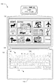
図1は、織物の接着技術を本明細書に記載の装置に使用する際に動作可能な例示的な実装形態の環境100の図である。図示の環境100は、フレキシブル・ヒンジ106を介して入力装置104に物理的及び通信可能に結合されたコンピュータ装置102の例を含む。この特定の例では、コンピュータ装置102は、タブレットコンピュータ装置として構成される。しかしながら、これは限定されるものではなく、コンピュータ装置102は、携帯電話、ウェアラブル装置、ラップトップ、ゲーム装置等の様々な他の方法で構成することができる。こうして、コンピュータ装置102は、実質的なメモリ及びプロセッサリソースを有するフルリソース装置から、限定されたメモリ及び/又は処理リソースを有する低リソース装置に及んでもよい。コンピュータ装置102の例示的な実装形態は、図13を参照して以下で説明する。
Example Environment FIG. 1 is a diagram of an
コンピュータ装置102は、入力/出力モジュール108を含むものとして示されており、入力/出力モジュール108は、コンピュータ装置102の入力処理及びレンダリング出力に関する機能を表す。入力装置104のキー、表示装置110によって表示される仮想キーボードのキーに対応する機能に関する入力等の様々な異なる入力は、入出力モジュール108によって処理され、入力装置104及び/又は表示装置110のタッチスクリーン機能を介して認識され得るタッチ・ジェスチャーを識別し、このタッチ・ジェスチャーに対応する動作を実行させる。こうして、入力/出力モジュール108は、キーの押下、タッチ・ジェスチャー、コンピュータ装置102のカメラ機能を介して認識されるタッチレス・ジェスチャー等を含む入力のタイプ同士の間の区分を認識し、活用することによって様々な異なる入力技術をサポートすることができる。
The
図示の例では、入力装置104は、上面114を含むシャーシ112を有するように構成される。上面114は、キーの配列を有するキーボード116とタッチ入力装置118とを含む入力部分を含む。この例示的な配置は、例示のみを目的として提示され、キーボード116及びタッチ入力装置118のための他の配置及び位置も企図される。さらに、ゲームコントローラ、楽器等を模倣した構成等の非従来型の他の構成も企図される。こうして、入力装置104、キーボード116、及び/又はタッチ入力装置118は、様々な異なる機能をサポートするために様々な異なる構成をとることができる。
In the illustrated example, the
様々な実装形態によれば、入力装置104は、特定の材料、例えば、プラスチック、金属、様々な合金、炭素繊維等のインスタンス及び/又はこれらの組合せ等から製造される。さらに、入力装置104の上面114及び/又は他の面の様々な部分は、織物層で積層される。少なくともいくつかの実装形態では、上面114全体が、キーボード116及びタッチ入力装置118を覆う織物層で積層される。織物は、例えば、上面114を覆うように積層される連続した織物シートであってもよい。1つ又は複数の実装形態によれば、織物は、一体化した織物層を形成するために一緒に積層された織物材料の複数の個別の層を含んでもよい。
According to various implementations, the
織物層に使用され得る材料の例には、天然材料(例えば、綿、絹、羊毛、皮革、リネン等)から作られた織物、合成材料(例えば、ナイロン、ポリエステル、アラミド、炭素繊維等)から作られた織物、及びそれらの組合せが含まれる。これらの例は、限定するものとして解釈すべきではなく、様々な他のタイプ及びインスタンスの織物を、特許請求の範囲に記載された実装形態に従って採用してもよい。一般に、織物層は、特定のタイプ及び/又は材料の組合せから形成され得る可撓性材料の層を表す。 Examples of materials that can be used for the fabric layer include fabrics made from natural materials (eg, cotton, silk, wool, leather, linen, etc.), synthetic materials (eg, nylon, polyester, aramid, carbon fibers, etc.). Included are fabrics made and combinations thereof. These examples should not be construed as limiting, and various other types and instances of fabrics may be employed in accordance with the claimed implementations. Generally, a textile layer represents a layer of flexible material that may be formed from a particular type and / or combination of materials.
様々な実装形態によれば、キーボード116のキーは、上面114の織物層に印刷及び/又はエッチングされたキーの視覚的表現である視覚化キーを含む。織物層の下には、複数の感圧キーを含むセンサ基板がある。例えば、個々の視覚化キーは、織物層の下にある対応する感圧キーの位置を特定する。こうして、視覚化キーにより、ユーザが、織物層の対応する領域を押すことにより、適切な感圧キーの位置を特定して作動させることができる。
According to various implementations, the keys of
1つ又は複数の実装形態では、タッチ入力装置118は、織物層の下の入力装置104に取り付けられ、物理的タッチを検出するように構成された容量性センサ又は他のセンサを介してユーザ入力を受け取ることができる。
In one or more implementations, the
上述したように、入力装置104は、この例では、フレキシブル・ヒンジ106を使用することによって、コンピュータ装置102に物理的且つ通信可能に結合される。フレキシブル・ヒンジ106は、可撓性であり、ヒンジによってサポートされる回転運動が、ピンによってサポートされる機械的回転とは対照的に、ヒンジを形成する材料の屈曲(例えば、曲げ)によって実現され、その実装形態も企図される。さらに、このようなフレキシブル回転は、1つ又は複数の方向(例えば、図において垂直方向)の動きをサポートするが、コンピュータ装置102に対する入力装置104の横方向の動き等、他の方向への動きを制限するように構成してもよい。これは、電力状態、アプリケーション状態等を変更するために使用されるセンサを整列させる等、コンピュータ装置102に関連する入力装置104の一貫した整列をサポートするために使用される。
As mentioned above, the
添付図面に示された様々な装置及び構成要素は、必ずしも縮尺通りに示されていないことを理解されたい。従って、添付図面に示される様々な装置及び構成要素の間の様々な寸法、位置関係、及び/又は動作関係は、特許請求の範囲に記載された実施形態を限定するものと解釈すべきではない。 It should be understood that the various devices and components shown in the accompanying drawings are not necessarily shown to scale. Therefore, various dimensions, positional relationships, and / or operational relationships between the various devices and components shown in the accompanying drawings should not be construed as limiting the claimed embodiments. ..
コンピュータ装置102及び入力装置104を紹介した後、1つ又は複数の実装形態によるコンピュータ装置102及び入力装置104のいくつかの例示的な姿勢の説明を検討する。
After introducing
姿勢の例
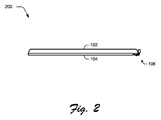
様々な実施形態によれば、コンピュータ装置102及び入力装置104の様々な異なる姿勢がサポートされる。例えば、入力装置104がコンピュータ装置102の表示装置110に対して配置され、それにより図2の例示的な姿勢200に示すようにカバーとして機能するように、フレキシブル・ヒンジ106によって回転運動をサポートしてもよい。こうして、入力装置104は、コンピュータ装置102の表示装置110を危害から保護するように機能することができる。
Posture Examples According to various embodiments, various different poses of
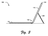
図3の例示的な姿勢に示されるように、タイピング構成をサポートしてもよい。この姿勢では、入力装置104は、表面に対して平らに置かれ、コンピュータ装置102は、例えば、コンピュータ装置102の背面に配置されたキックスタンド302等を使用することによって、表示装置110を見ることができる角度で配置される。一般に、キックスタンド302は、コンピュータ装置102の様々な異なる姿勢を可能にする支持要素を表す。キックスタンド302は、例えばキックスタンド302、従ってコンピュータ装置102が様々な異なる姿勢をとることができるようにコンピュータ装置102に回転可能に取り付けられており、それによって、異なる動作シナリオがサポートされる。代替的又は追加的に、摩擦ヒンジを用いて、キーボード及びタブレットを、ラップトップ構成等の互いに対して所定の位置に保持することができる。当然のことながら、本明細書で明示的に示され、議論された以外の様々な他の姿勢もサポートされる。
Typing configurations may be supported, as shown in the exemplary pose of FIG. In this position, the
実装形態の例
このセクションでは、1つ又は複数の実施態様による、装置への織物の接着のためのいくつかの例示的な実施態様について議論する。
Example Implementations This section discusses some exemplary implementations for adhering fabrics to devices according to one or more implementations.
図4は、コンピュータ装置102から取り外された入力装置104の上面図400を示す。入力装置104は、入力装置104の外縁部を表す周縁部402を含む。この特定の例では、周縁部402は、入力装置104の少なくとも3つの側辺に配置される。入力装置104は、この入力装置104をコンピュータ装置102に接続するのを可能にするコネクタ404をさらに含む。少なくともいくつかの実装形態では、コネクタ404によって、マグネット、クリップ、プラグ、ラッチ、及び/又は他の適切な着脱可能な取り付け技術等を使用して、入力装置104のコンピュータ装置102への着脱可能な接続を可能にする。
FIG. 4 shows a
コネクタ404は、本明細書では、入力装置104をコンピュータ装置102に物理的に取り付けることを可能にするものとして示しているが、他の代替的又は追加的な実装形態が企図されることを理解されたい。例えば、コネクタ404は、入力装置104とコンピュータ装置102との間のデータの無線通信を可能にし得る。例えば、物理的接続に追加して又はこの代替として、コネクタ404は、無線データ通信のための無線機能、例えば無線トランシーバとして実装してもよい。従って、コネクタ404は、一般に、入力装置104とコンピュータ装置102との間のインターフェイスを表す。
The
入力装置104のフレキシブル・ヒンジ106は、第1のヒンジ領域406と第2のヒンジ領域408とを含み、それらの間にスパイン410を有する。一般に、第1のヒンジ領域406及び第2のヒンジ領域408は、コンピュータ装置102等の取り付けられた装置に対する入力装置104の回転を可能にするフレキシブル・ヒンジ106の可撓性部分を表す。スパイン410は、フレキシブル・ヒンジ106の可撓性を制御し、例えば特定の剛性及び/又は運動プロファイルに調整することを可能にするフレキシブル・ヒンジ106の剛性部分を表す。
The
図5は、1つ又は複数の実装形態による入力装置104の側断面図500を示す。断面図500は、入力装置104が、上部織物層502及び底部織物層504で積層される(laminated)ことを示す。一般に、上部織物層502及び底部織物層504は、入力装置104の内部コンポーネント506の上に積層された異なる層の織物を表す。内部コンポーネント506は、入力装置104によって様々なタイプの入力を検出するのを可能にする内部入力コンポーネントを表す。例えば、内部コンポーネント506は、キーボード116、タッチ入力装置118等の構成要素等の様々な電気コンポーネントが取り付けられたプリント回路基板(PCB)を含む。上部織物層502及び底部織物層504は、任意の適切なラミネート及び/又は接着技術を使用して内部コンポーネント506に積層することができる。
FIG. 5 illustrates a side
断面図500は、第1のヒンジ領域406と、第2のヒンジ領域408と、これらの間のスパイン410とを有するフレキシブル・ヒンジ106をさらに示す。この特定の例では、第1のヒンジ領域406及び第2のヒンジ領域408は、少なくとも部分的に上部織物層502から底部織物層504への接着により形成されることに留意されたい。さらに、スパイン410は、上部織物層502と底部織物層504との間に挿入され、第1のヒンジ領域406と第2のヒンジ領域408とを少なくとも部分的に分離する材料を表す。
The
コネクタ404も示されている。上述したように、コネクタ404は、入力装置104とコンピュータ装置102との間の機械的及び/又は電気的接続を提供する。
周縁部402の断面がさらに示される。一般に、周縁部402は、底部織物層504の外縁部に接着された上部織物層502の外縁部を表す。例えば、上部織物層502の表面積及び底部織物層504の表面積は、内部コンポーネント506の表面積より大きく、それによって各織物層が、内部コンポーネント506の外縁を超えて重なり合う。以下でさらに詳細に説明するように、周縁部402に沿った上部織物層502の底部織物層504への接着は、周縁部402に沿ったそれぞれの織物層同士の間の接合の耐久性を高めるために、織物層の他の部分よりも厚い接着層を利用いてもよい。
A cross section of the
図6は、1つ又は複数の実装形態による入力装置104の正面断面図600を示す。断面図600は、内部コンポーネント506に積層された上部織物層502及び底部織物層504を示す。さらに、入力装置104の両側に沿って位置付けされた周縁部402の異なる側辺が示されている。とりわけ、断面図600は、上部織物層502及び底部織物層504が内部コンポーネント506と重なり、入力装置104の外縁に沿って互いに接着されることを示すのに役立つ。
FIG. 6 illustrates a front
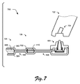
図7は、1つ又は複数の実装形態によるコンピュータ装置102及び入力装置104の部分的な側断面図700を示す。断面図700において、入力装置104は、計算装置102から切り離されている。
FIG. 7 illustrates a partial side
断面図700は、フレキシブル・ヒンジ106を横切って、内部コンポーネント506及びスパイン410の両側に積層される上部織物層502及び底部織物層504を示す。上部織物層502及び底部織物層504は、第1のヒンジ領域406及び第2のヒンジ領域408を横切って互いに少なくとも部分的に積層される。
The
断面図700は、電気的接続部702を介して内部コンポーネント506に電気的に接続されるコネクタ404をさらに示す。一般に、電気的接続部702によって、内部コンポーネント506とコネクタ404との間で電気信号が導通するのを可能にする。電気的接続部702は、内部コンポーネント506から第2のヒンジ領域408、スパイン410、及び第1のヒンジ領域406を介してコネクタ404に配線されるワイヤ配線及び/又は他の導電性材料等の様々な方法で実装することができる。
The
様々な実装形態によれば、電気的接続部702は、フレキシブル・ヒンジ106の幅に及んでいないが、フレキシブル・ヒンジ106の部分及び/又は複数の部分を通って経路が決められる。こうして、フレキシブル・ヒンジ106は、一般に、上部織物層502及び底部織物層504が、電気的接続部702の上に積層される部分と、上部織物層502及び底部織物層504が互いに積層される部分と、を含む。
According to various implementations, the
様々な実装形態によれば、コネクタ404は、コンピュータ装置102の受信機704との係合を介してコンピュータ装置102に接続可能である。一般に、受信機704は、入力装置104のコンピュータ装置102への着脱可能な接続を可能にするコネクタ404を受容するように構成される。受信機704は、電気信号が入力装置104の内部コンポーネント506とコンピュータ装置102のコンポーネントとの間で経路決めされるように、コネクタ404と電気的に接続するようにさらに構成される。例えば、入力装置104の内部コンポーネント506によって検出される入力が、電気的接続部702を介してコネクタ404に、次に受信器704を介して、コンピュータ装置102のコンポーネントに経路指定される。
According to various implementations, the
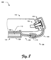
図8は、1つ又は複数の実装形態によるコンピュータ装置102及び入力装置104の部分的な側断面図800を示す。断面図800において、入力装置104は、コンピュータ装置102に取り付けられる。コネクタ404は、例えば、受信器704に接続される。少なくともいくつかの実装形態では、断面図800は、図2に示される姿勢200の詳細な例示を表す。例えば、断面図800は、コンピュータ装置102のディスプレイ110に対して位置付けされた入力装置104を示す。
FIG. 8 illustrates a partial side
断面図800は、フレキシブル・ヒンジ106を横切って、内部コンポーネント506及びスパイン410の両側に積層された上部織物層502及び底部織物層504を示す。上部織物層502及び底部織物層504は、第1のヒンジ領域406及び第2のヒンジ領域408を横切って互いに少なくとも部分的に積層される。
The
この特定の構成に示されるように、フレキシブル・ヒンジ106は、入力装置104をコンピュータ装置102に対して、例えばコンピュータ装置102に対して位置付けされた様々な位置に移動するのを可能にするように屈曲する。例えば、第1のヒンジ領域406及び第2のヒンジ領域408の屈曲によって、入力装置104がコンピュータ装置102に対して異なる位置に回転している間に、コネクタ404が受信器704と係合した状態を維持するのを可能にする。
As shown in this particular configuration, the
少なくともいくつかの実装形態では、第1のヒンジ領域406及び第2のヒンジ領域406は、入力装置104の他の部分よりも可撓性を有しており、従って、入力装置104の他の部分よりも曲がりに対する抵抗が少ない。以下でさらに詳細に説明するように、このような可撓性の増大は、入力装置104の様々な領域で上部織物層502を底部織物層504に接合するために使用される接着剤の量及び/又は配置を変化させることによって実現され得る。
In at least some implementations, the
入力装置104は、コンピュータ装置102に物理的に結合されるものとして示されているが、本明細書で説明する実装形態は、例えば、入力装置104とコンピュータ装置102との物理的接続とは独立した、入力装置104のコンピュータ装置102への無線接続を使用してもよい。例えば、入力装置104及びコンピュータ装置102は、Bluetooth(登録商標)、WiFi(登録商標)ダイレクト、近距離無線通信(NFC)等の無線接続を介してデータを通信することができる。こうして、少なくともいくつかの実装形態では、入力装置104は、コンピュータ装置への物理的接続とは独立した、様々な異なるコンピュータ装置に入力機能を提供することができる。
Although the
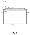
図9は、1つ又は複数の実装形態による織物層902の内部図900を示す。例えば、織物層902は、入力装置104のアセンブリの一部として積層される前の、上部織物層502及び/又は底部織物層504の1つ又は複数を表す。
FIG. 9 illustrates an
織物層902は、第1の接着ゾーン904、第2の接着ゾーン906、第3の接着ゾーン908、及び第4の接着ゾーン910を含む。一般に、異なる接着ゾーンは、織物層902の異なる部分に対応しており、接着剤の厚さ及び/又は異なるタイプの接着剤を利用して、異なる剛性及び/又は可撓性プロファイル等の異なる性能属性を実現する。
The
第1の接着ゾーン904は、例えば、入力装置104の周縁部402を組み立てるのを可能にするように接着剤が塗布された織物層902の部分に対応する。第1の接着ゾーン904は、接着ゾーン906によって規定されるエッジを除いて、織物層902の周縁に延びることに留意されたい。従って、別の織物層が織物層902に組み立てられると、織物層の周縁部は、第1の接着ゾーン904に位置する接着剤を介して接着され、こうして入力装置104の周縁部402を形成する。
The
様々な実装形態によれば、接着ゾーン904内に配置された接着剤は、織物層902の他の接着ゾーン内の接着剤よりも厚い。接着ゾーン904内により厚い接着層を配置することにより、入力装置104の周縁部402に剛性及び耐久性を与える。例えば、接着ゾーン904内の接着剤の厚さを増大させることにより、周縁部402に沿って互いに異なる織物層の剥離及び剥がれを軽減する。
According to various implementations, the adhesive disposed in
第2の接着ゾーン906は、一般に、フレキシブル・ヒンジ106の第1のヒンジ領域406と位置的に一致し、第3の接着ゾーン908は、一般に、フレキシブル・ヒンジ106の第2のヒンジ領域408と位置的に一致する。様々な実装形態によれば、第2の接着ゾーン906及び第3の接着ゾーン908の接着剤の厚さは、第1の接着ゾーン904の接着剤の厚さよりも薄い。第2の接着ゾーン906及び第3の接着ゾーン908により薄い接着層を利用することにより、織物層902を別のそれぞれの織物層に接着したときに、第1のヒンジ領域406及び第2のヒンジ領域408が可撓性を維持するのを可能にする。例えば、第2の接着ゾーン906及び第3の接着ゾーン908に接着剤の薄い層を配置することにより、フレキシブル・ヒンジ106の可撓性が促進される。上記のように、入力装置104がコンピュータ装置102に取り付けられると、フレキシブル・ヒンジ106の可撓性によって、コンピュータ装置102に対して異なる位置に入力装置104を回転することが可能になる。
The
さらに、第2の接着ゾーン906と第3の接着ゾーン908との間で織物層902にスパイン410を接着することが示されている。一般に、スパインは、プラスチック、金属、炭素繊維等の剛性材料から形成される。スパイン410は、フレキシブル・ヒンジ106の剛性を提供して、フレキシブル・ヒンジ106の過剰な可撓性(例えば、フロピネス(floppiness))を低減する。
Further, adhering the
第4の接着ゾーン910は、一般に、入力装置104の内部コンポーネント506に接着される織物層902の一部を表す。第4の接着ゾーン910は、例えば、第1の接着ゾーン及び第3の接着ゾーン908によってそのエッジに規定される。一般に、第4の接着ゾーン910の接着剤の厚さは、第1の接着ゾーン904の接着剤の厚さよりも薄く、且つ第2の接着ゾーン906及び/又は第3の接着ゾーン908の接着剤の厚さとほぼ等しくてもよい。
少なくともいくつかの実装形態では、接着ゾーン904に塗布される接着剤の厚さは、他の接着ゾーンに塗布される接着剤の厚さの少なくとも2倍である。例えば、接着ゾーン904に塗布される接着剤の厚さは、50.8μm(0.002inches)+/−2.54μm(0.0001inches)であるが、接着ゾーン906、908のそれぞれに塗布される接着剤の厚さは、25.4μm(0.001inches)+/−2.54μm(0.0001inches)である。従って、織物層902に従って構成された2つの織物層が互いに積層されるとき、101.6μm(0.004inches)+/−5.08μm(0.0002inches)の接着ゾーン904での接着剤の厚さの合計が実現され、接着ゾーン906,908のそれぞれでの接着剤の厚さは、50.8μm(0.002inches)+/−2.54μm(0.0001inches)である。
In at least some implementations, the thickness of the adhesive applied to
あるいはまた、接着剤を、一方の織物層に塗布し、別の織物層に塗布しなくてもよい。こうして、2つの織物層は、織物層の1つのみの接着ゾーンに塗布された接着剤を介して一緒に接着してもよい。そのような場合、上記で提供された例示的な接着剤の厚さは、単一の織物層上で倍にしてもよい。 Alternatively, the adhesive may be applied to one fabric layer and not another. Thus, the two fabric layers may be adhered together via an adhesive applied to only one adhesion zone of the fabric layer. In such cases, the thickness of the exemplary adhesive provided above may be doubled on a single fabric layer.
これらの寸法は、例示のみを目的として提供されており、開示された実装態様に従って様々な異なる接着剤の厚さを様々な接着ゾーンで使用してもよいことを理解されたい。 It should be understood that these dimensions are provided for illustrative purposes only and that different adhesive thicknesses may be used in different bond zones in accordance with the disclosed implementations.
様々な実装形態によれば、上部織物層502及び底部織物層504は、織物層902として実施することができる。こうして、上部織物層502及び底部織物層504を入力装置104の他の構成要素に組み立てることは、織物層902について指定された接着ゾーンを利用する織物層の積層を含む。例えば、以下の実装シナリオを検討する。
According to various implementations,
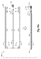
図10aは、入力装置104の様々な部分を組み立てるための例示的な実装シナリオ1000を示す。シナリオ1000に提示された視点は、入力装置104の構成要素の側面断面を表す。
FIG. 10 a illustrates an
シナリオ1000の上部は、上部織物層502、底部織物層504、電気的接続部702を介してコネクタ404に接続された内部コンポーネント506、及びスパイン410を示す。一般に、シナリオ1000の上部は、組立て前の入力装置104の様々な構成要素を表す。
The top of
上部織物層502の内面1002には、接着剤が塗布される接着ゾーン1004a、接着ゾーン1006a、接着ゾーン1008a、及び接着ゾーン1010aを含むいくつかの接着ゾーンが規定される。1つ又は複数の実装態様によれば、これらの接着ゾーンは、一般に、図9を参照して紹介した接着ゾーンの実装態様を表す。例えば、接着ゾーン1004aは接着ゾーン904を表し、接着ゾーン1006aは接着ゾーン906を表し、接着ゾーン1008aは接着ゾーン908を表し、接着ゾーン1010aは接着ゾーン910を表す。
The
上部織物層502と同様に、底部織物層504の内面1012には、接着剤が塗布される接着ゾーン1004b、接着ゾーン1006b、接着ゾーン1008b、及び接着ゾーン1010bを含むいくつかの接着ゾーンが規定される。1つ又は複数の実装態様によれば、これらの接着ゾーンは、一般に、図9を参照して紹介した接着ゾーンの実装態様を表す。例えば、接着ゾーン1004bは接着ゾーン904を表し、接着ゾーン1006bは接着ゾーン906を表し、接着ゾーン1008bは接着ゾーン908を表し、接着ゾーン1010bは接着ゾーン910を表す。
Similar to the
上述したように、接着剤の厚さ及び/又は接着剤のタイプは、異なる接着ゾーンの間で変化する。例えば、接着ゾーン1004a、1004bに塗布される接着剤は、他の接着ゾーンに塗布される接着剤よりも厚い。代替的又は追加的に、接着ゾーン1004a、1004bに塗布される接着剤のタイプは、他の接着ゾーンに塗布される接着剤のタイプとは異なる。例えば、熱活性化フィルムが、接着ゾーン1004a、1004bに利用され、別のタイプの接着剤が他の接着ゾーンに利用される。例えば、他の接着ゾーンは、スプレー式接着剤、感圧式接着剤、接触式接着剤等を利用することができる。
As mentioned above, the thickness of the adhesive and / or the type of adhesive varies between different adhesive zones. For example, the adhesive applied to
シナリオ1000の下部に進むと、上部織物層502及び底部織物層504は、入力装置104の他の構成要素に互いに積層される。例えば、上部織物層502及び底部織物層504は、内部コンポーネント506の異なる側面に接着ゾーン1010a、1010bの接着剤によって、内部コンポーネント506に積層される。接着ゾーン1004a、1004bは、互いに積層され、周縁部402を形成する。
Proceeding to the bottom of the
さらに、接着ゾーン1006a、1006bは、電気的接続部702に及び互いに積層され、フレキシブル・ヒンジ106の第1のヒンジ領域406を形成する。少なくともいくつかの実装形態では、電気的接続部702は、第1のヒンジ領域406の全幅に及んでいない。例えば、電気的接続部702は、第1のヒンジ領域406の一部及び/又は複数の下位部分に亘って実装される。こうして、接着ゾーン1006a、1006bの接着剤によって、上部織物層502及び底部織物層504を、第1のヒンジ領域406のいくつかの領域で電気的接続部702に、及び第1のヒンジ領域406の他の領域で互いに接着する。
In addition, the
同様に、接着ゾーン1008a、1008bは、電気的接続部702に及び互いに積層され、フレキシブル・ヒンジ106の第2のヒンジ領域408を形成する。少なくともいくつかの実装形態では、電気的接続部702は、第2のヒンジ領域408の全幅に及んでいない。例えば、電気的接続部702は、第2のヒンジ領域408の一部及び/又は複数の下位部分に亘って実装される。こうして、接着ゾーン1008a、1008bの接着剤によって、上部織物層502及び底部織物層504を、第2のヒンジ領域408のいくつかの領域で電気的接続部702に、及び第2のヒンジ領域408の他の領域で互いに接着する。
Similarly, the
接着ゾーンは、スパイン410に対して明示的に特定されていないが、上部織物層502及び底部織物層504もスパイン410に積層されることを理解されたい。例えば、少なくともいくつかの実装形態では、上部織物層502の接着ゾーン1008a、1008bは互いに隣接しており、こうしてそれらの隣接するエッジはスパイン410に接着される。同様の状況が、接着ゾーン1008a、1008bに当てはまり、底部織物層504をスパイン410に接着する。
Although the adhesive zone is not explicitly specified for
従って、シナリオ1000は、様々な材料特性を達成するために、異なる接着ゾーンを異なる厚さ及び/又はタイプの接着剤と共に利用できることを示している。例えば、接着ゾーン1004a、1004bにより厚い及び/又はより耐久性のある接着剤を利用することにより、周縁部402の耐久性が向上し、周縁部402に沿った上部織物層502及び/又は底部織物層504の剥がれ及び/又は剥離が軽減される。さらに、接着ゾーン1006a、1006b及び/又は接着ゾーン1008a、1008bに沿ってより薄い及び/又はより可撓性を有する接着層を利用することにより、フレキシブル・ヒンジの可撓性が向上する。
Thus,
少なくともいくつかの実装形態では、織物層502、504は、一旦入力装置104に積層されると取り外すことができず、こうして取り外し可能なカバーとは異なり、区別される。従って、本明細書で議論される技術は、装置の1つ又は複数の外面に積層された織物層を含む一体化された装置を提供する。これは、取り外し可能なカバーに対して、様々な利点を提供し、その利点は、典型的な取り外し可能なカバーよりも軽い、低プロファイルの織物層を含む。
In at least some implementations, the fabric layers 502, 504 are non-removable once laminated to the
図10bは、接着ゾーン1004aを含む上部織物層502の拡大部分図1012を示す。接着ゾーン1004aは、特定の厚さ、例えば上部織物層502の表面に対する接着剤の高さを有する接着層1014を含む。例えば、接着層1014が熱活性化フィルムから形成されることを検討する。そのような実装形態では、熱活性化フィルムは、上部織物層502の表面に対して決定された法線方向(例えば、90度)に特定の高さを有する。
FIG. 10b shows an enlarged
図10cは、接着ゾーン1006a、1008aを含む上部織物層502の拡大部分図1016を示す。接着ゾーン1006a、1008aは、特定の厚さ、例えば上部織物層502の表面に対する接着剤の高さを有する接着層1018を含む。例えば、接着層1018が熱活性化フィルムから形成されることを検討する。そのような実装形態では、熱活性化フィルムは、上部織物層502の表面に対して決定された法線方向(例えば、90度)に特定の高さを有する。
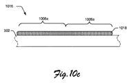
FIG. 10c shows an enlarged
図10bの接着層1014の厚さと図10cの接着層1018の厚さとを比較すると、接着層1014は接着層1018より厚い。本明細書の他の箇所で説明したように、接着ゾーン1004aにより厚い接着層を設けることにより、例えば入力装置402の周縁部402等の織物層の周縁部の耐久性が向上する。
Comparing the thickness of
接着ゾーン1006a、1008aにおける接着剤の厚さは同じであるように示されているが、少なくともいくつかの実装形態では、接着ゾーン1006a、1008aにおける接着剤の厚さは互いに異なってもよいことを理解されたい。1つ又は複数の実装形態によれば、上部織物層502を参照して、図10b、図10cに示される接着剤の特性は、底部織物層504に等しく適用される。
Although the adhesive thicknesses in
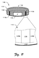
図11は、1つ又は複数の実装形態によるウェアラブル装置1100の一例を示す。ウェアラブル装置1100は、シャーシ1104の1つ又は複数の外面上に織物層1102と積層され、その外面にディスプレイ1106を含む。織物層1102は、他の織物層を参照して上述したような様々な方法で実装することができる。
FIG. 11 illustrates an example of
ウェアラブル装置1100は、ギャップ1108を含み、フレキシブル領域1110a及びフレキシブル領域1110bで屈曲するように構成される。例えば、フレキシブル領域1110a、1110bで屈曲することにより、ギャップ1108が拡張し、ウェアラブル装置1100をユーザの手首の周りに配置することができる。
The
図11には、さらに、フレキシブル領域1110bにおける織物層1102の底面の部分図1112が示される。部分図1112に示されるように、織物層1102はいくつかの異なる接着ゾーンに分割される。例えば、接着ゾーン1114は、ウェアラブル装置1100の周縁部に沿って延びる織物層1102の部分を表す。さらに、接着ゾーン1116は、フレキシブル領域1110bを覆う織物層1102の部分を表す。接着ゾーン1118a及び接着ゾーン1118bは、フレキシブル領域1110bに隣接して生ずる織物層1102の部分を表す。
FIG. 11 further shows a
様々な実施形態によれば、接着剤の厚さ及び/又は接着剤のタイプは、異なる接着ゾーンの間で変えることができる。例えば、接着ゾーン1114における接着剤の厚さは、ウェアラブル装置1100の周縁部に沿った織物層1102の耐久性を向上させ、織物層1102の剥離及び剥がれを軽減等するために、他の接着ゾーンよりも厚い。接着ゾーン1116における接着剤の厚さは、フレキシブル領域1110bでの可撓性を可能にする等のために、他の接着ゾーンにおける接着剤の厚さよりも薄い。接着ゾーン1118a、1118bにおける接着剤の厚さは、接着ゾーン1114における接着剤の厚さより薄く、及び/又は接着ゾーン1116における接着剤の厚さよりも厚いものであってもよい。この接着ゾーンプロファイルは、フレキシブル領域1110bを参照して説明したが、同様の接着ゾーンプロファイルをフレキシブル領域1110aに適用してもよい。
According to various embodiments, the thickness of the adhesive and / or the type of adhesive can vary between different adhesive zones. For example, the thickness of the adhesive in the
1つ又は複数の実装形態によれば、織物層1102は、単一の連続層の織物及び/又は互いに重ねられた複数の連続層の織物として実装される。こうして、本明細書で議論される実装形態は、単一の織物上の複数の異なる接着ゾーンを提供して、単一の織物の異なる領域に異なる特性を提供する。 According to one or more implementations, the fabric layer 1102 is implemented as a single continuous layer fabric and / or multiple continuous layer fabrics stacked on top of each other. Thus, the implementations discussed herein provide a plurality of different adhesive zones on a single fabric, providing different properties to different regions of a single fabric.
ウェアラブル装置1100は、腕時計のフォームファクタとして示されているが、本明細書で議論される装置への織物の接着の実装は、ウェアラブルなものとそうでないものとの広範な異なるフォームファクタに適用されることを理解されたい。
Although
実装形態について、電子装置のシナリオを参照して説明しているが、本明細書で議論される装置への織物の接着の技術は、織物で積層された任意の項目についての様々な異なる使用シナリオで使用することができ、電子装置のシナリオに限定されるものではない。 Although implementations are described with reference to electronic device scenarios, the technique of gluing textiles to the devices discussed herein is based on a variety of different usage scenarios for any item laminated with textiles. Can be used in and is not limited to electronic device scenarios.
装置への織物の接着のいくつかの例示的な実装形態について説明したが、ここでは、1つ又は複数の実装形態による例示的な手順を検討する。 Having described several exemplary implementations of adhering fabric to a device, we now consider exemplary procedures according to one or more implementations.
手順の例
このセクションでは、1つ又は複数の実装形態による装置への織物の接着の例示的な手順について説明する。手順は、1つ又は複数のコンピュータ装置及び/又はモジュール等を介して実行される一連の操作(又は動作)として示されるが、必ずしも動作を実行するために示された順序に限定されるものではない。この例示的な手順は、図1の環境100に、図13のシステム1300に、及び/又は任意の他の適切な環境において採用してもよい。1つ又は複数の実装形態によれば、この手順は、本明細書に記載された例示的な実装シナリオの様々な態様を実行するための例示的な方法を説明する。少なくともいくつかの実装形態では、手順について説明したステップは、自動的且つユーザとの対話とは独立して実施される。
Example Procedure This section describes an exemplary procedure for adhering fabric to a device according to one or more implementations. A procedure is presented as a series of operations (or actions) performed through one or more computing devices and / or modules, etc., but is not necessarily limited to the order presented to perform the actions. Absent. This exemplary procedure may be employed in
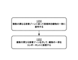
図12は、1つ又は複数の実施形態による方法のステップを説明するフロー図である。この方法は、例えば、1つ又は複数の実施形態による、複数の接着ゾーンを含む織物層を積層するための例示的な手順を説明する。 FIG. 12 is a flow diagram illustrating steps of a method in accordance with one or more embodiments. This method describes, for example, an exemplary procedure for laminating a fabric layer that includes multiple adhesive zones, according to one or more embodiments.
ステップ1200では、複数の異なる接着ゾーンに従って織物の一部に接着剤が塗布される。例えば、織物の部分は、織物の単一の部分を表す。一般に、異なる接着ゾーンは、それぞれの接着剤の厚さ及び/又はそれぞれの接着剤のタイプに関して互いに異なる。
In
ステップ1202では、複数の異なる接着ゾーンを介して織物の一部を構成要素に接着する。一般に、構成要素は、別の織物層、装置の内部コンポーネント(例えば、入力装置104の内部コンポーネント506)、装置の構造要素等の1つ又は複数の構成要素を含むことができる。様々な実装形態によれば、複数の異なる接着ゾーンは、耐久性、可撓性、視覚的外観等の違いを実現するために、異なる接着ゾーンでの織物部分に対して異なる材料特性をもたらす。
In
装置への織物の接着のための例示的な手順を議論したが、ここでは、1つ又は複数の実装形態によるシステム及び装置の例を検討する。 Having discussed an exemplary procedure for bonding fabrics to a device, consider now examples of systems and devices according to one or more implementations.
システム及び装置の例
図13は、例示的なコンピュータ装置1302を含む例示的なシステム1300を示しており、システム1300は、本明細書に記載の様々な技術を実施することができる1つ又は複数のコンピュータシステム及び/又は装置を表す。少なくともいくつかの実装形態では、コンピュータ装置1302は、上述したコンピュータ装置102の実装形態を表す。コンピュータ装置1302は、例えば、ユーザの1つ又は複数の手によって把持され、担持されるように形成され、サイズ決めされたハウジングを使用するモバイル構成をとるように構成することができ、その例には、携帯電話、モバイル・ゲーム及び音楽装置、ウェアラブル装置、及びタブレットコンピュータが含まれるが、他の例も企図される。
Exemplary Systems and Devices FIG. 13 illustrates an
例示されたコンピュータ装置1302は、処理システム1304、1つ又は複数のコンピュータ可読媒体1306、及び1つ又は複数のI/Oインターフェイス1308を含み、それらは互いに通信可能に結合される。図示していないが、コンピュータ装置1302は、様々な構成要素を互いに結合するシステムバス又は他のデータ及びコマンド転送システムをさらに含むことができる。システムバスは、メモリバス又はメモリコントローラ、周辺バス、ユニバーサルシリアルバス、及び/又は様々なバス・アーキテクチャのいずれかを利用するプロセッサ又はローカルバス等、様々なバス構造の任意の1つ又は組合せを含むことができる。制御線やデータ線等の様々な他の例も企図される。 The illustrated computing device 1302 includes a processing system 1304, one or more computer-readable media 1306, and one or more I / O interfaces 1308, which are communicatively coupled to each other. Although not shown, computing device 1302 may further include a system bus or other data and command transfer system that couples various components together. The system bus includes any one or combination of various bus structures, such as a memory bus or memory controller, a peripheral bus, a universal serial bus, and / or a processor or local bus utilizing any of a variety of bus architectures. be able to. Various other examples of control lines, data lines, etc. are also contemplated.
処理システム1304は、ハードウェアを使用して1つ又は複数の動作を実行する機能を表す。従って、処理システム1304は、プロセッサ、機能ブロック等として構成され得るハードウェア要素1310を含むものとして示される。これは、特定用途向け集積回路又は1つ又は複数の半導体を使用して形成された他の論理装置としてハードウェアに実装することができる。ハードウェア要素1310は、それらハードウェア要素が形成される材料又はその中で使用される処理機構によって限定されるものではない。例えば、プロセッサは、半導体及び/又はトランジスタ(例えば、電子集積回路(IC))から構成することができる。そのような状況において、プロセッサ実行可能命令は、電子的に実行可能な命令であってもよい。
The processing system 1304 represents the functionality that uses hardware to perform one or more operations. Accordingly, processing system 1304 is shown as including
コンピュータ可読記憶媒体1306は、メモリ/ストレージ1312を含むものとして示されている。メモリ/ストレージ1312は、1つ又は複数のコンピュータ可読媒体に関連するメモリ/ストレージ容量を表す。メモリ/ストレージ要素1312は、揮発性媒体(ランダムアクセスメモリ(RAM)等)及び/又は不揮発性媒体(読取り専用メモリ(ROM)、フラッシュメモリ、光ディスク、磁気ディスク等)を含むことができる。メモリ/ストレージ要素1312は、固定式媒体(例えば、RAM、ROM、固定ハードドライブ等)だけでなく、リムーバブル媒体(例えば、フラッシュメモリ、リムーバブルハードドライブ、光ディスク等)を含むことができる。コンピュータ可読媒体1306は、以下でさらに説明するように、様々な他の方法で構成することができる。 Computer readable storage media 1306 is shown as including memory / storage 1312. Memory / storage 1312 represents memory / storage capacity associated with one or more computer-readable media. The memory / storage element 1312 can include volatile media (such as random access memory (RAM)) and / or non-volatile media (such as read only memory (ROM), flash memory, optical disks, magnetic disks, etc.). The memory / storage element 1312 can include removable media (eg, flash memory, removable hard drive, optical disk, etc.) as well as fixed media (eg, RAM, ROM, fixed hard drive, etc.). Computer readable media 1306 can be configured in various other ways, as described further below.
入出力インターフェイス1308は、ユーザがコマンド及び情報をコンピュータ装置1302に入力するのを可能にし、また、様々な入出力装置を使用してユーザ及び/又は他の構成要素又は装置に情報を提示することを可能にする機能を表す。入力装置の例には、キーボード、カーソル制御装置(例えば、マウス)、マイクロフォン、スキャナ、タッチ機能(例えば、物理的接触を検出するように構成された容量性又は他のセンサ)、カメラ(接触を伴わないジェスチャー等の動きを認識するために赤外線周波数等の可視又は非可視波長を使用する)等が含まれる。出力装置の例には、表示装置(例えば、モニタ又はプロジェクタ)、スピーカ、プリンタ、ネットワークカード、触覚応答装置等が含まれる。こうして、コンピュータ装置1302は、ユーザとの対話をサポートするための様々な方法で構成することができる。 The input / output interface 1308 allows a user to enter commands and information into the computing device 1302 and also presents information to the user and / or other components or devices using various input / output devices. Represents a function that enables Examples of input devices include a keyboard, cursor control device (eg mouse), microphone, scanner, touch function (eg capacitive or other sensor configured to detect physical contact), camera (touch contact). Use visible or invisible wavelengths such as infrared frequencies to recognize unattended gestures and other movements). Examples of output devices include display devices (eg, monitors or projectors), speakers, printers, network cards, tactile response devices, and the like. Thus, computing device 1302 can be configured in various ways to support interaction with a user.
コンピュータ装置1302は、入力装置1314に通信可能に及び物理的に結合されるものとしてさらに示されており、入力装置1314は、コンピュータ装置1302から通信可能に及び物理的に取り外し可能である。このように、様々な異なる入力装置を、多種多様な機能をサポートするために様々な構成を有するコンピュータ装置1302に結合することができる。この例では、入力装置1314は、感圧キー、機械スイッチ式キー等として構成され得る1つ又は複数のキー1316を含む。 Computing device 1302 is further shown as being communicatively and physically coupled to input device 1314, which is communicatively and physically removable from computing device 1302. In this manner, a variety of different input devices can be coupled to computing device 1302, which has a variety of configurations to support a wide variety of functions. In this example, the input device 1314 includes one or more keys 1316 that may be configured as pressure sensitive keys, mechanically switched keys, or the like.
入力装置1314は、様々な機能をサポートするように構成された1つ又は複数のモジュール1318を含むものとしてさらに示される。例えば、1つ又は複数のモジュール1318は、キー1316から受信したアナログ及び/又はデジタル信号を処理して、キーストロークが意図されているかどうかを判定し、入力が静止圧力を示すかどうかを判定し、コンピュータ装置1302との動作のための入力装置1314の認証をサポートするように構成することができる。 The input device 1314 is further shown as including one or more modules 1318 configured to support various functions. For example, one or more modules 1318 may process analog and / or digital signals received from keys 1316 to determine if a keystroke is intended and to determine if the input indicates quiescent pressure. , Input device 1314 for operation with computer device 1302 can be configured to support authentication.
本明細書では、ソフトウェア、ハードウェア要素、又はプログラムモジュールの一般的な文脈で様々な技術を説明した。一般に、そのようなモジュールは、特定のタスクを実行し、又は特定の抽象データタイプを実装するルーチン、プログラム、オブジェクト、要素、コンポーネント、データ構造等を含む。本明細書で使用される「モジュール」、「機能」及び「構成要素(要素、コンポーネント)」という用語は、一般に、ソフトウェア、ファームウェア、ハードウェア、又はそれらの組合せを表す。本明細書で説明される技術の特徴は、プラットフォームに依存しないものであり、様々なプロセッサを有する様々な商用コンピュータプラットフォーム上で実装され得ることを意味する。 Various techniques have been described herein in the general context of software, hardware elements, or program modules. In general, such modules include routines, programs, objects, elements, components, data structures, etc. that perform particular tasks or implement particular abstract data types. The terms "module", "function" and "component" as used herein generally refer to software, firmware, hardware, or a combination thereof. The features of the techniques described herein are platform independent and mean that they can be implemented on various commercial computer platforms with various processors.
説明したモジュール及び技術の実装形態は、何らかの形態のコンピュータ可読媒体上に格納してもよく、又はその媒体を介して伝送してもよい。コンピュータ可読媒体は、コンピュータ装置1302によってアクセスされ得る様々な媒体を含んでもよい。限定ではなく例として、コンピュータ可読媒体は、「コンピュータ可読記憶媒体」及び「コンピュータ可読信号媒体」を含むことができる。 Implementations of the described modules and techniques may be stored on or transmitted over some form of computer readable media. Computer readable media may include a variety of media that may be accessed by computing device 1302. By way of example, and not limitation, computer readable media may comprise "computer readable storage media" and "computer readable signal media."
「コンピュータ可読記憶媒体」は、単なる信号伝送、搬送波、又は信号そのものとは対照的に、情報の永続的記憶を可能にする媒体及び/又は装置を指してもよい。コンピュータ可読記憶媒体は、信号そのものを含まない。コンピュータ可読記憶媒体は、コンピュータ可読命令、データ構造、プログラムモジュール、論理素子/回路、又は他のデータ等の情報の記憶に適した方法又は技術で実装された揮発性及び不揮発性のリムーバブル及び非リムーバブルの媒体及び/又は記憶装置等のハードウェアを含む。コンピュータ可読記憶媒体の例には、限定されるものではないが、RAM、ROM、EEPROM、フラッシュメモリ又は他のメモリ技術、CD−ROM、デジタル多用途ディスク(DVD)又は他の光記憶装置、ハードディスク、磁気カセット、磁気テープ、磁気ディスク記憶装置又は他の磁気記憶装置、又は他の記憶装置、有形媒体、又は所望の情報を記憶するのに適しており、コンピュータによってアクセスされ得る製造物品が含まれ得る。 "Computer readable storage medium" may refer to a medium and / or device that allows for the persistent storage of information, as opposed to mere signal transmission, carrier waves, or the signal itself. The computer-readable storage medium does not include the signal itself. Computer-readable storage media are volatile and nonvolatile removable and non-removable implemented in any method or technology suitable for storing information such as computer-readable instructions, data structures, program modules, logic elements / circuits, or other data. Hardware such as a storage medium and / or a storage device. Examples of computer readable storage media include, but are not limited to, RAM, ROM, EEPROM, flash memory or other memory technology, CD-ROM, digital versatile disk (DVD) or other optical storage device, hard disk. , Magnetic cassettes, magnetic tapes, magnetic disk storage devices or other magnetic storage devices, or other storage devices, tangible media, or articles of manufacture suitable for storing desired information and accessible by a computer. obtain.
「コンピュータ可読信号媒体」は、ネットワーク等を介して、コンピュータ装置1302のハードウェアに命令を送信するように構成された信号担持(signal-bearing)媒体を指してもよい。信号媒体は、典型的には、コンピュータ可読命令、データ構造、プログラムモジュール、又は搬送波、データ信号、又は他の搬送機構等の変調データ信号内の他のデータを具体化することができる。信号媒体には、あらゆる情報配信媒体も含まれる。「変調されたデータ信号」という用語は、その特性の1つ又は複数を有する信号が、情報を信号に符号化するように設定又は変更された信号を意味する。限定ではなく例として、通信媒体には、有線ネットワーク又は直接有線接続等の有線媒体や、音響、RF、赤外線、及び他の無線媒体等の無線媒体が含まれる。 “Computer-readable signal medium” may refer to a signal-bearing medium configured to send instructions to the hardware of computing device 1302, such as over a network. Signal media typically may embody computer readable instructions, data structures, program modules, or other data in a modulated data signal such as a carrier wave, data signal, or other carrier mechanism. Signal media also includes any information delivery media. The term "modulated data signal" means a signal that has one or more of its characteristics set or changed in such a manner as to encode information in the signal. By way of example, and not limitation, communication media includes wired media such as a wired network or direct wired connection, and wireless media such as acoustic, RF, infrared, and other wireless media.
上述したように、ハードウェア要素1310及びコンピュータ可読媒体1306は、ハードウェア形式で実装されたモジュール、プログラマブル装置ロジック及び/又は固定装置ロジックを表しており、これらは、いくつかの実施形態では、1つ又は複数の命令を実行する等、本明細書に記載される技術の少なくともいくつかの態様を実施するように用いられる。ハードウェアは、集積回路又はオンチップシステムの構成要素、特定用途向け集積回路(ASIC)、フィールドプログラマブルゲートアレイ(FPGA)、複雑なプログラマブルロジック装置(CPLD)、及びシリコン又は他のハードウェア内の他の実装形態を含むことができる。この文脈では、ハードウェアは、ハードウェアおよび実行する命令を記憶するために利用されるハードウェア、例えば前述のコンピュータ可読記憶媒体によって具体化される命令及び/又はロジックによって規定されるプログラムタスクを実行する処理装置として動作することができる。
As mentioned above, the
前述したものの組合せも、本明細書に記載される様々な技術を実装するために使用してもよい。従って、ソフトウェア、ハードウェア、又は実行可能モジュールは、ある形態のコンピュータ可読記憶媒体上で及び/又は1つ又は複数のハードウェア要素1310によって具体化される1つ又は複数の命令及び/又はロジックとして実装してもよい。コンピュータ装置1302は、ソフトウェア及び/又はハードウェアモジュールに対応する特定の命令及び/又は機能を実装するように構成することができる。従って、コンピュータ装置1302によってソフトウェアとして実行可能なモジュールの実装は、例えば、コンピュータ可読記憶媒体及び/又は処理システム1304のハードウェア要素1310の使用によって、少なくとも部分的にハードウェアで実現することができる。命令及び/又は機能は、1つ又は複数の製造物品(例えば、コンピュータ装置1302及び/又は処理システム1304)によって実行可能/動作可能であり、本明細書に記載の技術、モジュール、及び例を実現することができる。
Combinations of the above may also be used to implement the various techniques described herein. Accordingly, software, hardware, or executable modules are one or more instructions and / or logic embodied on some form of computer readable storage media and / or embodied by one or
本明細書で議論される実装形態は、以下の例を含む。 The implementations discussed herein include the following examples.
例1:装置であって、この装置は、コンピュータ装置と;フレキシブル・ヒンジを介してコンピュータ装置にフレキシブルに取り付けられた入力装置であって、入力装置は、コンピュータ装置に対して複数の姿勢に回転可能である、入力装置と;を有しており、入力装置は、それぞれの接着ゾーンにおける接着剤の厚さに基づいて異なる接着ゾーンを介して織物層に積層され、接着ゾーンは、織物層の周縁部を入力装置に接着する第1の接着ゾーンと;織物層をフレキシブル・ヒンジに接着する第2の接着ゾーンと;を含み、第2の接着ゾーンにおける接着剤の厚さは、第1の接着ゾーンにおける接着剤の厚さ未満である。 Example 1: A device, which is a computer device; an input device flexibly attached to the computer device via a flexible hinge, the input device rotating in a plurality of positions relative to the computer device. An input device, which is possible, wherein the input device is laminated to the fabric layer via different adhesion zones based on the thickness of the adhesive in the respective adhesion zone, the adhesion zone comprising: A first adhesive zone for adhering the peripheral portion to the input device; a second adhesive zone for adhering the fabric layer to the flexible hinge; and the adhesive thickness in the second adhesive zone is It is less than the thickness of the adhesive in the adhesion zone.
例2:例1に記載の装置であって、入力装置は、コンピュータ装置に動作可能に取り付けられたキーボードを含む。 Example 2: The device described in example 1, wherein the input device comprises a keyboard operably attached to the computer device.
例3:例1又は2に記載の装置であって、入力装置は、コンピュータ装置に着脱可能に取り付けられる。 Example 3: The device according to example 1 or 2, wherein the input device is removably attached to the computer device.
例4:例1乃至3のいずれか1つに記載の装置であって、織物層は、一体化された織物シートを含む。 Example 4: The device according to any one of Examples 1 to 3, wherein the fabric layer comprises an integrated fabric sheet.
例5:例1乃至4のいずれか1つに記載の記載であって、第1の接着ゾーンは、織物層の周縁部に沿って位置付けされた熱活性化フィルムを利用して形成される。 Example 5: The description of any one of Examples 1 to 4, wherein the first adhesive zone is formed utilizing a heat activated film positioned along the periphery of the fabric layer.
例6:例1乃至5のいずれか1つに記載の装置であって、接着ゾーンは、織物層を入力装置の1つ又は複数の内部コンポーネントに接着する第3の接着ゾーンを含み、第3の接着ゾーンの接着剤の厚さは、第1の接着ゾーンの接着剤の厚さ未満である。 Example 6: The device according to any one of Examples 1 to 5, wherein the adhesive zone comprises a third adhesive zone for adhering the fabric layer to one or more internal components of the input device, the adhesive zone comprising: The adhesive thickness of the first adhesive zone is less than the adhesive thickness of the first adhesive zone.
例7:例1乃至6のいずれか1つに記載の装置であって、第1の接着ゾーンで利用される接着剤のタイプが、第2の接着ゾーンで利用される接着剤のタイプとは異なる。 Example 7: The apparatus according to any one of Examples 1 to 6, wherein the type of adhesive used in the first adhesive zone is the type of adhesive used in the second adhesive zone. different.
例8:例1乃至7のいずれか1つに記載の装置であって、織物層は、入力装置の内部コンポーネントの第1の面に積層され、装置は、さらに、内部コンポーネントの第2の面に積層される異なる織物層を含み、異なる織物層の周縁部が、第1の接着ゾーンにおける織物層の周縁部に積層され、入力装置の周縁部を形成する。 Example 8: The device according to any one of Examples 1 to 7, wherein the fabric layer is laminated to the first side of the internal component of the input device, the device further comprising a second side of the internal component. Different fabric layers that are laminated to each other, the periphery of the different fabric layers being laminated to the periphery of the fabric layer in the first adhesive zone to form the periphery of the input device.
例9:例1乃至8のいずれか1つに記載の装置であって、織物層は、入力装置の内部コンポーネントの第1の面に積層され、装置は、さらに、内部コンポーネントの第2の面に積層された異なる織物層を含み、異なる織物層は、第2の接着ゾーンにおける織物層に少なくとも部分的に積層されて、フレキシブル・ヒンジの少なくとも一部を形成する。 Example 9: The device of any one of Examples 1-8, wherein the fabric layer is laminated to a first surface of an internal component of the input device, the device further comprising a second surface of the internal component. Different fabric layers laminated to each other, the different fabric layers being at least partially laminated to the fabric layers in the second adhesive zone to form at least a portion of the flexible hinge.
例10:入力装置であって、この入力装置は、1つ又は複数の内部コンポーネントと;1つ又は複数の内部コンポーネントに接続され、入力装置をコンピュータ装置に接続するように構成されたインターフェイスと;1つ又は複数の内部コンポーネントの第1の面に積層された第1の織物層と;1つ又は複数の内部コンポーネントの第2の面に積層された第2の織物層と;を有しており、第1の織物層又は第2の織物層の1つ又は複数は、第1の織物層の周縁部を第2の織物層の周縁部に接着させて、入力装置の周縁部を形成する第1の接着ゾーンと;第1の織物層を第2の織物層に少なくとも部分的に接着して、入力装置をコンピュータ装置にフレキシブルに取り付けることを可能にするフレキシブル・ヒンジを形成する第2の接着ゾーンと;を含み、第2の接着ゾーンの接着剤の厚さは、第1の接着ゾーンの接着剤の厚さ未満である。 Example 10: An input device, the input device being one or more internal components; an interface connected to the one or more internal components, the interface being configured to connect the input device to a computing device; A first fabric layer laminated to a first side of the one or more internal components; and a second fabric layer laminated to a second side of the one or more internal components; And one or more of the first fabric layer or the second fabric layer adheres the peripheral portion of the first fabric layer to the peripheral portion of the second fabric layer to form the peripheral portion of the input device. A first adhesive zone; a second fabric layer at least partially adhered to the second fabric layer to form a flexible hinge that allows the input device to be flexibly attached to a computing device. Bonding zone ; Wherein the thickness of the adhesive of the second adhesive zone is less than the thickness of the first adhesive zone of the adhesive.
例11:例10に記載の入力装置であって、インターフェイスは、無線トランシーバ及び電気コネクタから構成されるグループから選択される。 Example 11: The input device according to example 10, wherein the interface is selected from the group consisting of a wireless transceiver and an electrical connector.
例12:例10又は11に記載の入力装置であって、第1の接着ゾーンが、第1の織物層の周縁部を第2の織物層の周縁部に接着する熱活性化フィルムを含む。 Example 12: The input device according to example 10 or 11, wherein the first adhesive zone comprises a heat activated film that adheres the peripheral edge of the first textile layer to the peripheral edge of the second textile layer.
例13:例10乃至12のいずれか1つに記載の入力装置であって、第1の織物層又は第2の織物層の1つ又は複数は、その上に第1の接着ゾーン及び第2の接着ゾーンを有する一体化された織物シートを含む。 Example 13: The input device according to any one of Examples 10 to 12, wherein one or more of the first fabric layer or the second fabric layer has a first adhesive zone and a second adhesive layer thereon. Including an integrated woven sheet having an adhesive zone of.
例14:例10乃至13のいずれか1つに記載の入力装置であって、第1の織物層又は第2の織物層の1つ又は複数は、第1の織物層又は第2の織物層の1つ又は複数を1つ又は複数の内部コンポーネントに接着する第3の接着ゾーンをさらに含む。 Example 14: The input device according to any one of Examples 10 to 13, wherein one or more of the first fabric layer or the second fabric layer is the first fabric layer or the second fabric layer. And a third adhesive zone for adhering one or more of the to one or more internal components.
例15:装置であって、この装置は、フレキシブル領域を含むシャーシと;複数の接着ゾーンを介してシャーシに積層された織物層と;を有しており、接着ゾーンは、織物層をシャーシの周縁部に積層する第1の接着ゾーンと、織物層をフレキシブル領域に積層する第2の接着ゾーンとを含み、第2の接着ゾーンの接着剤の厚さは、第1の接着ゾーンの接着剤の厚さよりも薄い。 Example 15: A device comprising a chassis including a flexible region; a fabric layer laminated to the chassis via a plurality of adhesive zones, the adhesive zone comprising the fabric layer of the chassis. A first adhesive zone for laminating on a peripheral edge and a second adhesive zone for laminating a textile layer on a flexible region, wherein the adhesive thickness of the second adhesive zone is the adhesive of the first adhesive zone. Thinner than.
例16:例15に記載の装置であって、装置は、コンピュータ装置に着脱可能に取り付けられるように構成された入力装置を含む。 Example 16: The apparatus according to Example 15, wherein the apparatus comprises an input device configured to be removably attached to the computing device.
例17:例15又は16に記載の装置であって、装置は、ウェアラブル装置を含む。 Example 17: The device as described in example 15 or 16, wherein the device comprises a wearable device.
例18:例15乃至17のいずれか1つに記載の装置であって、第1の接着ゾーンは、第2の接着ゾーンの熱活性化フィルム層よりも厚い熱活性化フィルム層を含む。 Example 18: The device of any one of Examples 15-17, wherein the first adhesive zone comprises a heat-activated film layer that is thicker than the heat-activated film layer of the second adhesive zone.
例19:例15乃至18のいずれか1つに記載の装置であって、第1の接着ゾーンは、第2の接着ゾーンとは異なるタイプの接着剤を含む。 Example 19: The device of any one of Examples 15-18, wherein the first adhesive zone comprises a different type of adhesive than the second adhesive zone.
例20:例15乃至19のいずれか1つに記載の装置であって、織物層は、織物層をフレキシブル領域に隣接するシャーシに積層する第3の接着ゾーンを含む。 Example 20: The device of any one of Examples 15-19, wherein the fabric layer includes a third adhesive zone that laminates the fabric layer to the chassis adjacent the flexible region.
結論
例示的な実装形態について、構造的特徴及び/又は方法論的動作に特有の言語で説明しているが、添付の特許請求の範囲に規定された実装形態は、説明された特定の機能又は動作に必ずしも限定されないことを理解されたい。むしろ、特定の特徴及び動作は、特許請求の範囲に記載された特徴を実施する例示的な形態として開示される。
CONCLUSION Although exemplary implementations are described in language specific to structural features and / or methodological acts, the implementations defined in the appended claims are not limited to the specific features or acts described. It should be understood that is not necessarily limited to. Rather, the specific features and acts are disclosed as example forms of implementing the claimed features.
Claims (20)
コンピュータ装置と、
フレキシブル・ヒンジを介して前記コンピュータ装置にフレキシブルに取り付けられた入力装置であって、前記フレキシブル・ヒンジによって前記入力装置がコンピュータ装置に対して複数の方向に回転可能であり、前記入力装置は、それぞれの接着ゾーンにおける接着剤の厚さ及び接着剤のタイプに基づいて異なる接着ゾーンを介して織物層に積層される、入力装置と、を有しており、
前記接着ゾーンは、
前記織物層の周縁部を前記入力装置に接着する第1の接着ゾーンと、
前記織物層を前記フレキシブル・ヒンジに接着する第2の接着ゾーンと、を含み、
前記第2の接着ゾーンにおける接着剤の厚さは、前記第1の接着ゾーンにおける接着剤の厚さ未満であり、前記第1の接着ゾーンで利用される接着剤のタイプは、第2の接着ゾーンで利用される接着剤のタイプとは異なる、
機器。 A device, which is
A computer device,
An input device flexibly attached to the computer device via a flexible hinge, wherein the flexible hinge allows the input device to rotate in a plurality of directions with respect to the computer device. An input device that is laminated to the fabric layer through different adhesive zones based on the adhesive thickness and adhesive type in the adhesive zone of
The adhesive zone is
A first adhesive zone for adhering the peripheral portion of the fabric layer to the input device;
A second adhesive zone for adhering the fabric layer to the flexible hinge;
The adhesive thickness in the second adhesive zone is less than the adhesive thickness in the first adhesive zone, and the type of adhesive utilized in the first adhesive zone is the second adhesive. Different from the type of adhesive used in the zone,
machine.
1つ又は複数の内部コンポーネントと、
該1つ又は複数の内部コンポーネントに接続され、当該入力装置をコンピュータ装置に接続するように構成されるインターフェイスと、
前記1つ又は複数の内部コンポーネントの第1の面に積層された第1の織物層と、
前記1つ又は複数の内部コンポーネントの第2の面に積層された第2の織物層と、を有しており、
前記第1の織物層及び前記第2の織物層の1つ又は複数が、
前記第1の織物層の周縁部を前記第2の織物層の周縁部に接着して当該入力装置の周縁部を形成する第1の接着ゾーンと、
前記第1の織物層を前記第2の織物層に少なくとも部分的に接着して当該入力装置の前記コンピュータ装置へのフレキシブルな取付けを可能にするフレキシブル・ヒンジを形成する第2の接着ゾーンと、を含み、
該第2の接着ゾーンの接着剤の厚さは、前記第1の接着ゾーンの接着剤の厚さ未満であり、前記第1の接着ゾーンで利用される接着剤のタイプは、前記第2の接着ゾーンで利用される接着剤のタイプと異なる、
入力装置。 An input device, wherein the input device is
One or more internal components,
An interface connected to the one or more internal components and configured to connect the input device to a computing device;
A first fabric layer laminated to a first side of the one or more internal components;
A second fabric layer laminated to a second side of the one or more internal components;
One or more of the first fabric layer and the second fabric layer,
A first bonding zone for bonding the peripheral edge of the first fabric layer to the peripheral edge of the second fabric layer to form the peripheral edge of the input device;
A second adhesive zone that at least partially adheres the first fabric layer to the second fabric layer to form a flexible hinge that allows flexible attachment of the input device to the computing device; Including,
The adhesive thickness of the second adhesive zone is less than the adhesive thickness of the first adhesive zone, and the type of adhesive utilized in the first adhesive zone is the second adhesive zone. Different from the type of adhesive used in the bonding zone,
Input device.
フレキシブル領域を含むシャーシと、
複数の接着ゾーンを介して前記シャーシに積層される織物層と、を有しており、
前記複数の接着ゾーンは、前記織物層を前記シャーシの周縁部に積層する第1の接着ゾーンと、前記織物層を前記フレキシブル領域に積層する第2の接着ゾーンとを含み、第2の接着ゾーンの接着剤の厚さは、第1の接着ゾーンの接着剤の厚さ未満であり、前記第1の接着ゾーンで利用される接着剤のタイプは、前記第2の接着ゾーンで利用される接着剤のタイプと異なる、
機器。 A device, which is
A chassis including a flexible area,
A fabric layer laminated to the chassis via a plurality of adhesive zones,
The plurality of adhesive zones include a first adhesive zone for laminating the fabric layer on a peripheral portion of the chassis and a second adhesive zone for laminating the fabric layer on the flexible region, and a second adhesive zone. Adhesive thickness is less than the adhesive thickness of the first adhesive zone, and the type of adhesive utilized in the first adhesive zone is the adhesive utilized in the second adhesive zone. Different from the type of agent,
machine.
Applications Claiming Priority (3)
| Application Number | Priority Date | Filing Date | Title |
|---|---|---|---|
| US14/584,777 | 2014-12-29 | ||
| US14/584,777 US9720453B2 (en) | 2014-12-29 | 2014-12-29 | Fabric adhesion to an apparatus |
| PCT/US2015/064169 WO2016109119A1 (en) | 2014-12-29 | 2015-12-07 | Fabric adhesion to an apparatus |
Publications (3)
| Publication Number | Publication Date |
|---|---|
| JP2018508915A JP2018508915A (en) | 2018-03-29 |
| JP2018508915A5 JP2018508915A5 (en) | 2018-12-27 |
| JP6692829B2 true JP6692829B2 (en) | 2020-05-13 |
Family
ID=54937387
Family Applications (1)
| Application Number | Title | Priority Date | Filing Date |
|---|---|---|---|
| JP2017552792A Active JP6692829B2 (en) | 2014-12-29 | 2015-12-07 | Adhesion of textiles to equipment |
Country Status (11)
| Country | Link |
|---|---|
| US (1) | US9720453B2 (en) |
| EP (1) | EP3241096B1 (en) |
| JP (1) | JP6692829B2 (en) |
| KR (1) | KR102370509B1 (en) |
| CN (1) | CN107111378B (en) |
| AU (1) | AU2015374527B2 (en) |
| BR (1) | BR112017010395A2 (en) |
| CA (1) | CA2967978C (en) |
| MX (1) | MX2017008582A (en) |
| RU (1) | RU2710661C2 (en) |
| WO (1) | WO2016109119A1 (en) |
Families Citing this family (17)
| Publication number | Priority date | Publication date | Assignee | Title |
|---|---|---|---|---|
| JP6055882B1 (en) * | 2015-08-19 | 2016-12-27 | レノボ・シンガポール・プライベート・リミテッド | Information processing device |
| CN107024963B (en) * | 2016-01-29 | 2020-09-25 | 联想(北京)有限公司 | Electronic equipment |
| US10466804B2 (en) * | 2017-01-12 | 2019-11-05 | Microsoft Technology Licensing, Llc | Composite unibody keyboard |
| KR102375542B1 (en) * | 2017-04-25 | 2022-03-18 | 삼성전자주식회사 | electronic device including connector module |
| CN112015282A (en) * | 2019-05-30 | 2020-12-01 | 富泰华工业(深圳)有限公司 | Keyboard cover and electronic device having the same |
| US11675440B2 (en) * | 2019-09-30 | 2023-06-13 | Microsoft Technology Licensing, Llc | Solvent free textile coating |
| US11239710B2 (en) | 2019-09-30 | 2022-02-01 | Microsoft Technology Licensing, Llc | Charging system including orientation control |
| EP4430335A2 (en) | 2021-11-12 | 2024-09-18 | reMarkable AS | Device mount for supporting a computing device |
| WO2023106239A1 (en) * | 2021-12-10 | 2023-06-15 | ソニーグループ株式会社 | Adhesive configuration, electronic equipment, and adhesion method |
| US12299218B2 (en) | 2023-06-11 | 2025-05-13 | Remarkable As | Active pen-stylus precise eraser |
| USD1092467S1 (en) | 2023-11-13 | 2025-09-09 | Remarkable As | Tablet computer |
| USD1107023S1 (en) | 2024-02-08 | 2025-12-23 | Remarkable As | Marker |
| USD1106208S1 (en) | 2024-02-08 | 2025-12-16 | Remarkable As | Marker |
| USD1115781S1 (en) | 2024-05-03 | 2026-03-03 | Remarkable As | Folio |
| CN121300642A (en) | 2024-07-08 | 2026-01-09 | 瑞马科宝股份有限公司 | Marker pen writing system |
| CN121300641A (en) | 2024-07-08 | 2026-01-09 | 瑞马科宝股份有限公司 | Marker pen protection system |
| CN121300639A (en) | 2024-07-08 | 2026-01-09 | 瑞马科宝股份有限公司 | Replaceable conductive marker tip |
Family Cites Families (19)
| Publication number | Priority date | Publication date | Assignee | Title |
|---|---|---|---|---|
| US3997229A (en) | 1975-09-15 | 1976-12-14 | Thomas & Betts Corporation | Flexible connecting means |
| US5318422A (en) | 1992-11-05 | 1994-06-07 | Erland Robert K | Vacuum bag molding apparatus with channel and spline edge-seal |
| GB2365132B (en) * | 2000-03-30 | 2003-01-08 | Electrotextiles Co Ltd | Manual input apparatus and processor |
| EP1282852A1 (en) | 2000-05-18 | 2003-02-12 | Eleksen Limited | Data input device |
| KR100658267B1 (en) | 2005-08-31 | 2006-12-14 | 삼성에스디아이 주식회사 | Film Tray for Flexible Display Manufacturing |
| US7685676B2 (en) | 2006-02-24 | 2010-03-30 | Mc Clellan W Thomas | Living hinge |
| KR100938684B1 (en) * | 2007-10-16 | 2010-01-25 | 코오롱글로텍주식회사 | Electronic fabric and its manufacturing method |
| US20120011683A9 (en) | 2008-02-29 | 2012-01-19 | Kim David K J | Routing flexible printed circuit board through hinge of electronic device |
| US8830163B2 (en) * | 2008-12-12 | 2014-09-09 | Hewlett-Packard Development Company, L.P. | Integrated keyboard and touchpad |
| RU102185U1 (en) * | 2010-07-28 | 2011-02-20 | Фу-И СЮЙ | ELECTRONIC DEVICE SHELL STRUCTURE |
| US8787016B2 (en) | 2011-07-06 | 2014-07-22 | Apple Inc. | Flexible display devices |
| WO2013102214A1 (en) | 2011-12-30 | 2013-07-04 | Liberman Distributing And Manufacturing Co. | Extendable self-supporting material composites and manufacture thereof |
| US8873227B2 (en) * | 2012-03-02 | 2014-10-28 | Microsoft Corporation | Flexible hinge support layer |
| US9075566B2 (en) * | 2012-03-02 | 2015-07-07 | Microsoft Technoogy Licensing, LLC | Flexible hinge spine |
| US9158383B2 (en) * | 2012-03-02 | 2015-10-13 | Microsoft Technology Licensing, Llc | Force concentrator |
| US9064654B2 (en) * | 2012-03-02 | 2015-06-23 | Microsoft Technology Licensing, Llc | Method of manufacturing an input device |
| US20140132550A1 (en) * | 2012-03-02 | 2014-05-15 | Microsoft Corporation | Electrical Contacts and Connectors |
| US9315004B2 (en) * | 2012-03-06 | 2016-04-19 | Apple Inc. | Accessory units for consumer electronic devices and related assemblies and methods |
| US9205629B2 (en) | 2013-03-15 | 2015-12-08 | Ann Livingston-Peters | Composite structure with a flexible section forming a hinge |
-
2014
- 2014-12-29 US US14/584,777 patent/US9720453B2/en active Active
-
2015
- 2015-12-07 KR KR1020177020615A patent/KR102370509B1/en not_active Expired - Fee Related
- 2015-12-07 RU RU2017122455A patent/RU2710661C2/en active
- 2015-12-07 EP EP15813661.4A patent/EP3241096B1/en active Active
- 2015-12-07 AU AU2015374527A patent/AU2015374527B2/en not_active Ceased
- 2015-12-07 WO PCT/US2015/064169 patent/WO2016109119A1/en not_active Ceased
- 2015-12-07 CN CN201580071667.3A patent/CN107111378B/en active Active
- 2015-12-07 JP JP2017552792A patent/JP6692829B2/en active Active
- 2015-12-07 MX MX2017008582A patent/MX2017008582A/en unknown
- 2015-12-07 CA CA2967978A patent/CA2967978C/en active Active
- 2015-12-07 BR BR112017010395A patent/BR112017010395A2/en not_active Application Discontinuation
Also Published As
| Publication number | Publication date |
|---|---|
| EP3241096B1 (en) | 2021-08-11 |
| WO2016109119A1 (en) | 2016-07-07 |
| KR102370509B1 (en) | 2022-03-03 |
| US9720453B2 (en) | 2017-08-01 |
| US20160187933A1 (en) | 2016-06-30 |
| EP3241096A1 (en) | 2017-11-08 |
| AU2015374527A1 (en) | 2017-05-25 |
| CA2967978A1 (en) | 2016-07-07 |
| MX2017008582A (en) | 2017-11-15 |
| CN107111378B (en) | 2020-09-29 |
| RU2017122455A3 (en) | 2019-07-17 |
| KR20170101950A (en) | 2017-09-06 |
| AU2015374527B2 (en) | 2020-07-16 |
| BR112017010395A2 (en) | 2017-12-26 |
| CA2967978C (en) | 2022-06-21 |
| JP2018508915A (en) | 2018-03-29 |
| CN107111378A (en) | 2017-08-29 |
| RU2710661C2 (en) | 2019-12-30 |
| RU2017122455A (en) | 2018-12-27 |
Similar Documents
| Publication | Publication Date | Title |
|---|---|---|
| JP6692829B2 (en) | Adhesion of textiles to equipment | |
| JP6435366B2 (en) | Flexible hinge and removable connection | |
| US9678542B2 (en) | Multiple position input device cover | |
| US9064654B2 (en) | Method of manufacturing an input device | |
| KR102395676B1 (en) | Fabric laminated touch input device | |
| CN106462192B (en) | Mounting wedge for flexible materials | |
| US20160299537A1 (en) | Flexible Hinge and Removable Attachment | |
| US20150227212A1 (en) | Method of Manufacturing an Input Device | |
| CN106030473A (en) | Texture and graphics formation techniques | |
| CN104272221B (en) | Input equipment manufactures |
Legal Events
| Date | Code | Title | Description |
|---|---|---|---|
| A521 | Request for written amendment filed |
Free format text: JAPANESE INTERMEDIATE CODE: A523 Effective date: 20181116 |
|
| A621 | Written request for application examination |
Free format text: JAPANESE INTERMEDIATE CODE: A621 Effective date: 20181116 |
|
| A977 | Report on retrieval |
Free format text: JAPANESE INTERMEDIATE CODE: A971007 Effective date: 20191127 |
|
| A131 | Notification of reasons for refusal |
Free format text: JAPANESE INTERMEDIATE CODE: A131 Effective date: 20191203 |
|
| A521 | Request for written amendment filed |
Free format text: JAPANESE INTERMEDIATE CODE: A523 Effective date: 20200302 |
|
| TRDD | Decision of grant or rejection written | ||
| A01 | Written decision to grant a patent or to grant a registration (utility model) |
Free format text: JAPANESE INTERMEDIATE CODE: A01 Effective date: 20200317 |
|
| A61 | First payment of annual fees (during grant procedure) |
Free format text: JAPANESE INTERMEDIATE CODE: A61 Effective date: 20200415 |
|
| R150 | Certificate of patent or registration of utility model |
Ref document number: 6692829 Country of ref document: JP Free format text: JAPANESE INTERMEDIATE CODE: R150 |
|
| R250 | Receipt of annual fees |
Free format text: JAPANESE INTERMEDIATE CODE: R250 |
|
| R250 | Receipt of annual fees |
Free format text: JAPANESE INTERMEDIATE CODE: R250 |
|
| R250 | Receipt of annual fees |
Free format text: JAPANESE INTERMEDIATE CODE: R250 |