JP6692246B2 - Construction machinery - Google Patents
Construction machinery Download PDFInfo
- Publication number
- JP6692246B2 JP6692246B2 JP2016152630A JP2016152630A JP6692246B2 JP 6692246 B2 JP6692246 B2 JP 6692246B2 JP 2016152630 A JP2016152630 A JP 2016152630A JP 2016152630 A JP2016152630 A JP 2016152630A JP 6692246 B2 JP6692246 B2 JP 6692246B2
- Authority
- JP
- Japan
- Prior art keywords
- filter
- plate
- lock
- impact
- air filter
- Prior art date
- Legal status (The legal status is an assumption and is not a legal conclusion. Google has not performed a legal analysis and makes no representation as to the accuracy of the status listed.)
- Expired - Fee Related
Links
- 238000010276 construction Methods 0.000 title claims description 33
- 238000001816 cooling Methods 0.000 claims description 43
- 239000000428 dust Substances 0.000 claims description 33
- 238000011144 upstream manufacturing Methods 0.000 claims description 18
- 230000000903 blocking effect Effects 0.000 claims 1
- 238000005452 bending Methods 0.000 description 4
- 238000003780 insertion Methods 0.000 description 4
- 230000037431 insertion Effects 0.000 description 4
- 238000002834 transmittance Methods 0.000 description 4
- 230000006835 compression Effects 0.000 description 3
- 238000007906 compression Methods 0.000 description 3
- 230000008602 contraction Effects 0.000 description 3
- 230000007423 decrease Effects 0.000 description 3
- 230000001681 protective effect Effects 0.000 description 3
- 239000002826 coolant Substances 0.000 description 2
- 230000007257 malfunction Effects 0.000 description 1
- 239000000463 material Substances 0.000 description 1
- 238000000034 method Methods 0.000 description 1
- 230000004048 modification Effects 0.000 description 1
- 238000012986 modification Methods 0.000 description 1
- 230000035939 shock Effects 0.000 description 1
- 125000006850 spacer group Chemical group 0.000 description 1
- 230000001360 synchronised effect Effects 0.000 description 1
Images


Description
本発明は、油圧ショベル等の建設機械に関するものである。 The present invention relates to a construction machine such as a hydraulic excavator.
一般に、建設機械にはエンジンルームが設けられており、その内部に、エンジン、エンジンを冷却する冷却器(ラジエータ等)、冷却器に対して冷却風を送るファン等が配置されている。特許文献1には、防塵装置を備えた建設機械が開示されている。防塵装置は、冷却器に塵埃が流入することを防止するために、フィルタを備えている。フィルタは、ファンの回転により形成された冷却風の流路において冷却器の上流側に配置されており、前記冷却風に随伴される塵埃を捕捉する。このため、冷却器への塵埃の付着が抑制される。また、当該防塵装置は、フィルタに付着した塵埃を脱離するために、フィルタを上方に移動させた後、落下させる塵埃除去手段を備えている。 In general, a construction machine is provided with an engine room, in which an engine, a cooler (a radiator, etc.) for cooling the engine, a fan for sending cooling air to the cooler, and the like are arranged. Patent Document 1 discloses a construction machine equipped with a dustproof device. The dustproof device is provided with a filter in order to prevent dust from flowing into the cooler. The filter is arranged on the upstream side of the cooler in the flow path of the cooling air formed by the rotation of the fan, and captures dust accompanying the cooling air. Therefore, the adhesion of dust to the cooler is suppressed. In addition, the dustproof device includes a dust removing unit that moves the filter upward and then drops the dust in order to remove the dust attached to the filter.
特許文献1に示された技術では、フィルタを上方に移動させるために塵埃除去手段がフィルタに近接して配置されている。このため、塵埃除去手段が車体に対するフィルタの着脱経路を遮る位置に配置されている。この結果、フィルタの着脱時に、塵埃除去手段の一部を取り外したり分解する必要があり、フィルタの装着作業が複雑化するという問題があった。 In the technique disclosed in Patent Document 1, the dust removing means is arranged close to the filter in order to move the filter upward. For this reason, the dust removing means is arranged at a position that blocks the attachment / detachment route of the filter with respect to the vehicle body. As a result, when the filter is attached or detached, it is necessary to remove or disassemble a part of the dust removing means, which complicates the attachment work of the filter.
本発明は、フィルタの着脱を容易に実現するとともに、フィルタに付着した塵埃を脱離することが可能な建設機械を提供することを目的とする。 An object of the present invention is to provide a construction machine capable of easily attaching and detaching a filter and removing dust adhering to the filter.
本発明の一の局面に係る建設機械は、車体と、エンジンと、前記エンジンを冷却する冷却器と、前記冷却器に対して冷却風を送るファンと、前記冷却風の流路において前記冷却器の上流側に配置され、前記冷却風が通過するとともに、前記車体に対して着脱可能なフィルタと、前記車体に配置され、前記フィルタを支持するフィルタ支持部と、前記フィルタ支持部に支持された前記フィルタに衝撃を付与することで前記フィルタに捕集された塵埃を脱離させる衝撃付与部と、前記衝撃付与部が、前記フィルタの着脱時に当該フィルタが通過する着脱経路から退避して前記フィルタの着脱を許容する離間位置と、前記着脱経路を遮り前記フィルタに前記衝撃を付与する作動位置との間で移動可能なように、前記衝撃付与部を支持する支持機構と、を有する。 A construction machine according to an aspect of the present invention is a vehicle body, an engine, a cooler that cools the engine, a fan that sends cooling air to the cooler, and the cooler in a passage of the cooling air. A filter that is disposed on the upstream side of the vehicle and that allows the cooling air to pass through and that is removable from the vehicle body; a filter support portion that is disposed on the vehicle body and supports the filter; and a filter support portion that is supported by the filter support portion. The impact applying unit that detaches the dust collected by the filter by applying an impact to the filter, and the impact applying unit retracts from the attachment / detachment path through which the filter passes when attaching / detaching the filter, and the filter A support mechanism that supports the impact applying portion so as to be movable between a separated position that allows attachment / detachment of the filter and an operating position that blocks the attachment / detachment path and applies the impact to the filter. Having.
本構成によれば、冷却風に含まれる塵埃が冷却器に付着することが、フィルタによって抑止される。また、フィルタに塵埃が付着しフィルタの透過率が低下した場合であっても、衝撃付与部がフィルタに衝撃を付与することによって、塵埃を脱離させることができる。更に、衝撃付与部は、支持機構によって離間位置と作動位置との間で移動可能とされている。このため、フィルタの着脱が容易かつスムーズに実現可能とされる。 According to this configuration, the filter prevents dust contained in the cooling air from adhering to the cooler. Further, even when dust adheres to the filter and the transmittance of the filter decreases, the impact can be applied to the filter by the impact applying unit to remove the dust. Furthermore, the impact imparting section is movable by the support mechanism between the separated position and the operating position. Therefore, it is possible to easily and smoothly attach and detach the filter.
上記の構成において、前記着脱経路を遮り前記フィルタが前記フィルタ支持部から脱離することを防止するロック位置と、前記着脱経路から退避して前記フィルタの着脱を許容するロック解除位置との間で位置変更が可能なロック機構を更に有し、前記支持機構は、前記ロック機構から構成されており、前記ロック機構が前記ロック解除位置に配置されると前記衝撃付与部が前記離間位置に配置され、前記ロック機構が前記ロック位置に配置されると前記衝撃付与部が前記作動位置に配置されるものでもよい。 In the above configuration, between a lock position that blocks the attachment / detachment path and prevents the filter from being detached from the filter support portion, and a lock release position that retracts from the attachment / detachment path and allows attachment / detachment of the filter. The support mechanism further comprises a lock mechanism capable of changing a position, and the support mechanism is composed of the lock mechanism. When the lock mechanism is arranged in the lock release position, the impact applying section is arranged in the separated position. The impact imparting portion may be disposed at the operating position when the lock mechanism is disposed at the lock position.
本構成によれば、衝撃付与部がロック機構とともに移動することによって、フィルタの着脱がスムーズに実現される。また、ロック機構がロック位置に配置されることで、フィルタの脱離が防止される。 According to this configuration, the impact applying unit moves together with the lock mechanism, so that the filter can be smoothly attached and detached. Further, by disposing the lock mechanism at the lock position, detachment of the filter is prevented.
上記の構成において、前記ロック機構は、前記車体に支持された軸部と、前記フィルタをロックするロック片を含み前記軸部に対して回動可能な可動部材と、を備え、前記ロック解除位置において前記フィルタから離間して配置された前記ロック片が前記冷却風の通過方向上流側に移動し前記フィルタに当接するように、前記可動部材が前記軸部回りに回動されることで、前記ロック機構が前記ロック位置に移動し前記衝撃付与部が前記フィルタに対向して配置されることが望ましい。 In the above configuration, the lock mechanism includes a shaft portion supported by the vehicle body, and a movable member that includes a lock piece that locks the filter and is rotatable with respect to the shaft portion. In such a manner that the movable member is rotated around the shaft portion so that the lock piece arranged apart from the filter moves to the upstream side in the passage direction of the cooling air and comes into contact with the filter, It is desirable that the lock mechanism be moved to the lock position and the impact imparting section be arranged to face the filter.
本構成によれば、ロック機構の回動によって、ロック機構の位置変更に加え、衝撃付与部を離間位置と作動位置との間で移動させることができる。 According to this configuration, the impact applying portion can be moved between the separated position and the operating position in addition to the position change of the lock mechanism by the rotation of the lock mechanism.
上記の構成において、前記フィルタは、前記冷却風の通過方向と交差する装着方向に沿って前記着脱経路を通過しながら前記フィルタ支持部に装着され、かつ、前記装着方向に沿う二面および前記冷却風の通過方向に沿う四面を含む直方体形状からなり、前記ロック機構が前記ロック位置に至ると、前記ロック片は、前記フィルタのうち前記装着方向後端側の面および前記冷却風の通過方向上流側の面を押さえるように配置されるものでもよい。 In the above configuration, the filter is attached to the filter support portion while passing through the attachment / detachment path along an attachment direction that intersects the passage direction of the cooling air, and the two surfaces along the attachment direction and the cooling When the locking mechanism reaches the locking position, the locking piece has a surface on the rear end side in the mounting direction of the filter and an upstream side in the passing direction of the cooling air when the locking mechanism reaches the locking position. It may be arranged so as to press the side surface.
本構成によれば、ロック機構の回動に伴って、ロック片がフィルタの2面を確実に押さえ、フィルタをロックすることができる。 According to this configuration, as the lock mechanism rotates, the lock piece can reliably press the two surfaces of the filter to lock the filter.
上記の構成において、前記衝撃付与部は、シリンダと、前記シリンダから突出した突出位置と前記突出位置よりも前記シリンダ内に没入した没入位置との間で移動可能なように前記シリンダに支持されたプランジャと、を備えたソレノイドであって、前記フィルタ支持部は、少なくとも前記フィルタの下端部を支持するように配置され、前記フィルタは、前記プランジャによって押圧される被押圧部を備え、前記プランジャは、前記作動位置において前記被押圧部の下方に配置され、前記没入位置から前記突出位置への移動に伴って前記フィルタを押し上げ、前記突出位置から前記没入位置への移動に伴って前記フィルタを落下させ前記フィルタ支持部に当接させることで、前記フィルタに前記衝撃を付与するものでもよい。 In the above structure, the impact applying portion is supported by the cylinder so as to be movable between a cylinder, a protruding position protruding from the cylinder, and a retracted position retracted into the cylinder more than the protruding position. A plunger, and the filter support portion is arranged to support at least a lower end portion of the filter, the filter includes a pressed portion pressed by the plunger, the plunger Disposed below the pressed portion in the operating position, pushes up the filter with the movement from the retracted position to the projecting position, and drops the filter with the movement from the projecting position to the retracted position The impact may be applied to the filter by bringing it into contact with the filter support portion.
本構成によれば、衝撃付与部がソレノイドから構成されることで、フィルタを容易に上下移動させることができる。また、フィルタの落下時のエネルギーを利用して、フィルタから塵埃を脱離させることができる。 According to this configuration, since the impact applying unit is formed of the solenoid, the filter can be easily moved up and down. Further, it is possible to detach dust from the filter by utilizing the energy when the filter is dropped.
上記の構成において、前記ロック機構の前記可動部材は、前記軸部に回動可能に支持された第1プレートと、前記第1プレートに対して間隔をおいて配置され、前記軸部に回動可能に支持された第2プレートと、を備え、前記ロック片は、前記第1プレートおよび前記第2プレートが前記軸部回りに一体的に回動可能なように、前記軸部の軸方向に沿って前記第1プレートと前記第2プレートとを接続するものでもよい。 In the above structure, the movable member of the lock mechanism is disposed on the first plate rotatably supported on the shaft portion, and is arranged at a distance from the first plate to rotate on the shaft portion. A second plate that is movably supported, and the locking piece is arranged in the axial direction of the shaft portion so that the first plate and the second plate can rotate integrally around the shaft portion. The first plate and the second plate may be connected along the same.
本構成によれば、ロック機構が、第1プレートと第2プレートとを備えることで、ロック機構の剛性を高めることができる。 According to this configuration, since the lock mechanism includes the first plate and the second plate, the rigidity of the lock mechanism can be increased.
上記の構成において、前記軸部は、鉛直方向に沿って延びるように配置され、前記可動部材は、前記軸部回りに水平方向に沿って回動され、前記ロック機構の前記可動部材は前記軸部に回動可能に支持された第1プレートと、前記第1プレートの上方に間隔をおいて配置され、前記軸部に回動可能に支持された第2プレートと、を備え、前記ロック片は、前記第1プレートおよび前記第2プレートが前記軸部回りに一体的に回動可能なように、鉛直方向に沿って前記第1プレートと前記第2プレートとを接続し、前記ソレノイドは、上方を前記第2プレートによって覆われ、前記プランジャが上方に向かって突出するように、前記第1プレート上に固定され、前記第2プレートは、前記作動位置において前記プランジャの先端部が前記被押圧部に対向可能なように前記プランジャが挿通される孔部を備えているものでもよい。 In the above configuration, the shaft portion is arranged so as to extend in the vertical direction, the movable member is rotated around the shaft portion in the horizontal direction, and the movable member of the lock mechanism is the shaft. A lock plate and a first plate rotatably supported by the shaft portion; and a second plate rotatably supported by the shaft portion, the second plate being disposed above the first plate with a space therebetween. Is configured to connect the first plate and the second plate along a vertical direction so that the first plate and the second plate are integrally rotatable around the shaft portion, and the solenoid is The upper side is covered by the second plate and is fixed on the first plate so that the plunger protrudes upward, and the second plate has the distal end portion of the plunger pressed by the pressed position in the operating position. It said plunger to allow the counter may be one provided with a hole portion to be inserted into.
本構成によれば、ロック機構の第1プレートと第2プレートとの間にソレノイドを配置することで、ソレノイドがロック機構の外側に配置される場合と比較して、ロック機構および衝撃付与部をコンパクトに設定することができる。 According to this configuration, by disposing the solenoid between the first plate and the second plate of the lock mechanism, the lock mechanism and the impact imparting portion can be provided as compared with the case where the solenoid is disposed outside the lock mechanism. It can be set compactly.
上記の構成において、前記可動部材は、前記冷却風の流路において前記ソレノイドの上流側で前記ソレノイドを覆うように配置された保護部材を更に備えるものでもよい。 In the above configuration, the movable member may further include a protection member arranged on the upstream side of the solenoid in the flow path of the cooling air so as to cover the solenoid.
本構成によれば、冷却風に含まれる塵埃がソレノイドに付着することが、保護部材によって抑止される。 According to this configuration, the protective member prevents dust contained in the cooling air from adhering to the solenoid.
上記の構成において、前記保護部材は、鉛直方向に沿って前記第1プレートと前記第2プレートとを接続するものでもよい。 In the above configuration, the protection member may connect the first plate and the second plate along a vertical direction.
本構成によれば、保護部材によって、ロック機構の剛性を高めることができる。 According to this configuration, the protection member can enhance the rigidity of the lock mechanism.
上記の構成において、前記フィルタは、前記冷却風が通過する方向と交差する装着方向に沿って前記フィルタ支持部に装着され、前記衝撃付与部は、前記フィルタの前記装着方向後端側に対向するように前記車体に支持されているものでのよい。 In the above configuration, the filter is mounted on the filter support portion along a mounting direction that intersects a direction in which the cooling air passes, and the impact applying portion faces a rear end side of the filter in the mounting direction. It may be supported on the vehicle body as described above.
本構成によれば、冷却風の流れにおいてフィルタの上下流側に他の部材が配置されている場合でも、フィルタをフィルタ支持部に対して容易に着脱することができる。また、衝撃付与部が作動位置に移動されると、衝撃付与部はフィルタの装着方向後端側において着脱経路に進入するように配置される。このため、衝撃付与部がフィルタの脱離を防止する機能を備えることができる。 According to this configuration, even when another member is arranged on the upstream and downstream sides of the filter in the flow of the cooling air, the filter can be easily attached to and detached from the filter support portion. Further, when the impact applying section is moved to the operating position, the impact applying section is arranged so as to enter the attachment / detachment path on the rear end side in the mounting direction of the filter. Therefore, the impact applying unit can have a function of preventing detachment of the filter.
上記の構成において、前記フィルタの前記装着方向先端側に対向するように前記車体に支持され、前記フィルタに衝撃を付与することで、前記フィルタに捕集された塵埃を脱離させる副衝撃付与部を更に有するものでもよい。 In the above configuration, a sub-impact applying unit that is supported by the vehicle body so as to face the tip end side in the mounting direction of the filter, and imparts an impact to the filter to release the dust collected by the filter. May be further included.
本構成によれば、衝撃付与部に加え副衝撃付与部が備えられることによって、フィルタから塵埃を安定して脱離させることができる。 According to this configuration, since the secondary impact imparting portion is provided in addition to the impact imparting portion, dust can be stably desorbed from the filter.
上記の構成において、前記衝撃付与部および前記副衝撃付与部は、それぞれ、シリンダと、前記シリンダから突出した突出位置と前記突出位置よりも前記シリンダ内に没入した没入位置との間で移動可能なように前記シリンダに支持されたプランジャと、を備えたソレノイドであって、前記衝撃付与部および前記副衝撃付与部の各プランジャの前記没入位置から前記突出位置への移動動作は互いに同期して制御され、前記衝撃付与部および前
記副衝撃付与部の各プランジャの前記フィルタに対する当接位置が、略同じ高さに配置されているものでもよい。
In the above configuration, the impact applying portion and the sub impact applying portion are each movable between a cylinder, a projecting position projecting from the cylinder, and a retracted position retracted in the cylinder more than the projecting position. And a plunger supported by the cylinder, the movements of the plungers of the impact applying portion and the sub impact applying portion from the retracted position to the protruding position are controlled in synchronization with each other. Further, the abutting positions of the plungers of the impact applying portion and the secondary impact applying portion with respect to the filter may be arranged at substantially the same height.
本構成によれば、衝撃付与部および副衝撃付与部のプランジャによって、フィルタをバランスよく上下移動させることができる。 According to this structure, the filter can be vertically moved in a well-balanced manner by the plungers of the impact imparting portion and the sub impact imparting portion.
本発明によれば、フィルタの着脱を容易に実現するとともに、フィルタに付着した塵埃を脱離することが可能な建設機械が提供される。 According to the present invention, there is provided a construction machine capable of easily attaching and detaching a filter and removing dust adhering to the filter.
本発明の一実施形態の油圧ショベル10(建設機械)について、図1乃至図3を参照しながら説明する。図1は、本発明の一実施形態に係る油圧ショベル10の模式的な側面図である。図2は、図1に示す油圧ショベル10のガード15の内部の断面図である。図3は、図1に示す油圧ショベル10のガード15の内部の斜視図である。
A hydraulic excavator 10 (construction machine) according to an embodiment of the present invention will be described with reference to FIGS. 1 to 3. FIG. 1 is a schematic side view of a
図1および図2に示されるように、油圧ショベル10は、右走行クローラ及び左走行クローラを有する下部走行体11と、下部走行体11上に旋回可能に設けられた上部旋回体20(車体)と、作業アタッチメント13と、キャブ14と、ガード15と、を備えている。
As shown in FIGS. 1 and 2, a
作業アタッチメント13は、上部旋回体20に対して起伏可能となるように当該上部旋回体20に装着されている。作業アタッチメント13は、ブーム13aと、ブーム13aの先端部に連結されたアーム13bと、アーム13bの先端部に当該先端部に対して揺動可能に取り付けられたバケット13cと、を有する。ブーム13aは、ブームシリンダ13dの伸縮動作によって上部旋回体20に対して起伏する。アーム13bは、アームシリンダ13eの伸縮動作によってブーム13aに対して揺動する。バケット13cは、バケットシリンダ13fの伸縮動作によってアーム13bに対して揺動する。ブームシリンダ13d、アームシリンダ13eおよびバケットシリンダ13fは、それぞれ油圧式の油圧シリンダからなる。
The
キャブ14は、上部旋回体20の前方に配置され、油圧ショベル10の作業者が搭乗する。キャブ14には、油圧ショベル10を運転、操作するための各種の操作部材が配置されている。
The
ガード15は、キャブ14の後方に設けられている。ガード15は、エンジン31(図2参照)等を収容するエンジンルームを形成している。ガード15の外観はガードカバー16によって画定されている。図2に示されるように、ガード15内には、エンジン31と、油圧ポンプ32と、ラジエータ等の冷却器33と、ファン34と、吸気ダクト40と、エアフィルタ50と、エアクリーナ55(図3)と、が配置されている。油圧ポンプ32は、エンジン31の駆動軸の右端部に接続され、ガード15の右側部分に位置している。ガードカバー16の一部を構成する開閉カバー18(図3)が開けられると、図3に示すように、ガード15の内部が油圧ショベル10の外側に開放される。
The
ファン34は、エンジン31の駆動軸に接続されており、エンジン31の回転に合わせて回転する。ファン34の回転により、ガード15の外部から冷却器33に送られる冷却風W(図2)が形成される。
The
冷却器33は、ファン34の左方に配置されている。冷却器33は、エンジン31を冷却するための冷却媒体と冷却風Wとを熱交換させることによって冷却媒体を冷却する。なお、冷却器33に含まれるラジエータは、そのコア面が車両左右方向を向くように配設されている。
The cooler 33 is arranged on the left side of the
エアフィルタ50は、図2に示されるように、冷却風Wの流路において冷却器33の上流側(本実施形態では左方)に配置されている。エアフィルタ50は、冷却風Wを通過させるとともに、冷却風Wに随伴される塵埃を捕集(除去)する。このため、冷却器33への塵埃の付着が抑制される。エアフィルタ50は、上部旋回体20のガード15に対して着脱可能とされている。
As shown in FIG. 2, the
図2を参照して、吸気ダクト40は、空気流通方向の上流側から下流側に向かって開口した箱状のダクト本体41を有する。ダクト本体41は、エアフィルタ50と冷却器33との間に配置され、エアフィルタ50を通過した冷却風Wを冷却器33に導く。また、ダクト本体41には、エアフィルタ50を支持するためのエアフィルタ取付部42(図3)と、機器としてのエアクリーナ55を取り付ける機器取付部56(図3)とが設けられている。
With reference to FIG. 2, the
エアクリーナ55は、エンジン31に供給する空気を集塵するためのものであり、ダクト本体41からバイパスされた吸気管55aおよびエンジン31に向かう排気管55bに接続されている。
The
エアフィルタ取付部42(フィルタ支持部)は、ダクト本体41の上流側の開口部に設けられ、エアフィルタ50が着脱自在に取り付けられる。具体的に、エアフィルタ取付部42は、エアフィルタ50の上下面に沿ってそれぞれ配設された一対のガイド板43(上ガイド43a、下ガイド43b)と、車両の前方側に配設されたフィルタ保持部44と、を有する。更に、上部旋回体20は、エアフィルタ50の車両後方側に配設されたロック部材60(図3)(ロック機構)を有する。
The air filter attachment portion 42 (filter support portion) is provided in the opening on the upstream side of the
一対のガイド板43は、その間にエアフィルタ50を収容する。また、一対のガイド板43は、エアフィルタ50が着脱される際に、エアフィルタ50を案内するガイドとして機能する。下ガイド43bは、エアフィルタ50の下端部を支持するように、前後方向に長く延びている(図4(A)参照)。
The pair of guide plates 43 accommodate the
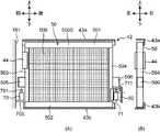
図4は、本実施形態に係るエアフィルタ50およびエアフィルタ取付部42の(A)正面図、(B)側面図である。図5は、本実施形態に係るロック部材60がエアフィルタ50から離間したロック解除位置に配置された状態の斜視図である。図6は、本実施形態に係るロック部材60がエアフィルタ50を固定するロック位置に配置された状態の斜視図である。図7は、エアフィルタ50が装着される様子を示す平面図(A)、(B)である。
FIG. 4 is a front view (A) and a side view (B) of the
図4(A)を参照して、エアフィルタ50は、塵埃を捕集する網状のフィルタ部500(網部)と、フィルタ部500の四辺を支持する枠部500Sと、を有している。本実施形態では、フィルタ部500は、矩形形状を備えている。枠部500Sは、上枠501と、下枠502と、前枠503と、後枠504と、前突起部505と、後突起部506(被押圧部)と、を備える。上枠501、下枠502、前枠503および後枠504は、それぞれ、フィルタ部500の上部、下部、前部および後部を支持する。
With reference to FIG. 4A, the
前突起部505は、前枠503から前方に向かって突出するように前枠503に固定された直方体形状の突起である。なお、前突起部505は、前枠503に一体的に形成されてもよい。同様に、後突起部506は、後枠504から後方に向かって突出するように後枠504に固定された直方体形状の突起である。後突起部506も、後枠504に一体的に形成されてもよい。前突起部505および後突起部506は、後記の前プランジャ701および後プランジャ711(図4)によって上方に押し上げられる。
The
図7(A)、(B)を参照して、本実施形態では、エアフィルタ50は冷却風Wがエアフィルタ50を通過する方向(図2参照、左右方向)と交差する装着方向(図7の矢印D71、前方向)に沿ってエアフィルタ取付部42(図3)に着脱される。この際、エアフィルタ50がガード15内を通過する経路が着脱経路Pと定義される。前述のフィルタ保持部44は、エアフィルタ50の前枠503(図4)の側壁面に当接することで、エアフィルタ50の前枠503側を前後および左右方向において位置決めする。このような構成によれば、冷却風Wの流れにおいてエアフィルタ50の上下流側にエアクリーナ55やダクト本体41などのような他の部材が配置されている場合でも、エアフィルタ50を容易に着脱することができる。
With reference to FIGS. 7A and 7B, in the present embodiment, the
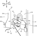
図3を参照して、ロック部材60は、ダクト本体41の後側の壁面である本体後壁41Rに回動可能に支持されている。ロック部材60は、エアフィルタ50がエアフィルタ取付部42から脱離することを防止する機能を備えている。そして、ロック部材60は、
エアフィルタ50の着脱経路P(図7(A))から離間して配置されエアフィルタ50の着脱を許容するロック解除位置と、着脱経路P内に配置されエアフィルタ50がエアフィルタ取付部42から脱離することを防止するロック位置との間で位置変更が可能とされている。また、図5、図6を参照して、ロック部材60は、エアフィルタ50に当接可能な可動部材61と、可動部材61の回動中心軸となる軸部材65と、軸部材65を保持する保持部材68とを備えている。
With reference to FIG. 3, the
The lock release position that is arranged apart from the attachment / detachment path P (FIG. 7A) of the
可動部材61は、エアフィルタ50の後枠504の後側および左側の壁面に当接するように折り曲げ形成されたロック板62(ロック片)と、ロック板62に一体形成されたアーム板63とを有する。ロック板62は、エアフィルタ50に当接し、エアフィルタ50をロックする機能を備える。ロック板62およびアーム板63は、1枚の板材が折り曲げられることで形成されている。アーム板63は、下板631(第1プレート)および上板632(第2プレート)を備える(図6)。下板631および上板632は、ロック板62のうちエアフィルタ50の後枠504に当接する面の上下両端縁から外方に折り曲げられた上下一対の板状部で構成されている。下板631および上板632は、後記の中心軸部65aに回動可能に支持されている。また、上板632は、下板631の上方に間隔をおいて配置されている。なお、ロック板62およびアーム板63について換言すれば、ロック板62は、下板631および上板632が中心軸部65a回りに一体的に回動可能なように、中心軸部65aの軸方向(鉛直方向)に沿って下板631と上板632とを接続する。
The
ロック板62は、エアフィルタ50の後枠504に当接することで、エアフィルタ50をフィルタ保持部44(図3)との間で挟持して固定する。ロック板62は、アーム板63とともに軸部材65の中心軸部65aを中心に回動されることによって、エアフィルタ50を固定するロック位置と、エアフィルタ50のロック状態を解除する解除位置との間で移動可能とされている。
The
アーム板63には、軸部材65の中心軸部65aが挿通される中心軸挿通孔63aと、軸部材65の係合軸部65bが挿通可能な係合軸挿通孔63bとが形成されている(図5)。中心軸挿通孔63aは、鉛直方向に沿って延び、アーム板63の上下一対の下板631および上板632を貫通するように形成されている。係合軸挿通孔63bは、アーム板63の上板632に形成されている。アーム板63の下板631および上板632の間には、保持部材68が配置されている。更に、アーム板63の上板632と、保持部材68の上面との間には、スペーサ部材69が配設されている。
The
軸部材65は、可動部材61の回動中心となる中心軸部65a(軸部)と、中心軸部65aと並列に延びる係合軸部65bとを有する。中心軸部65aと係合軸部65bとは、1本の軸材を折り曲げることで形成され、中心軸部65aの長さは係合軸部65bの長さよりも長く設定されている。中心軸部65aのうち、アーム板63よりも上方および下方には、それぞれストッパ板66が固定されている。下側のストッパ板66とアーム板63の下板631との間には、上側のストッパ板66がアーム板63の上板632に当接する方向、換言すれば、中心軸部65aが下方向に移動するように、保持部材68を付勢する圧縮バネ67が設けられている。
The
保持部材68は、1枚の板材がコの字状に折り曲げられることで形成されている。保持部材68には、折り曲げ形成された上下一対の板状部を貫通する保持孔68aと、上側の板状部を切り欠いてなる係合孔68bとが形成されている。保持孔68aには、軸部材65の中心軸部65aが軸方向に移動自在に保持されている。そして、中心軸部65aが軸方向に移動されると、係合軸部65bが連動して軸方向に移動する。この動作に応じて、係合軸部65bが係合孔68bに係合可能とされる。
The holding
ロック部材60が図6のロック位置に配置された状態では、可動部材61のロック板62は、エアフィルタ50の後壁504の後方側の側壁面及び上流側の面に当接している。これにより、エアフィルタ50がフィルタ保持部44(図3)とロック板62との間で挟持される。上記について換言すれば、エアフィルタ50は、冷却風の通過方向と交差する装着方向に沿って着脱経路Pを通過しながらエアフィルタ取付部42に装着される。更に、エアフィルタ50は、前記装着方向に沿う二面および冷却風の通過方向に沿う四面を含む直方体形状からなる。そして、ロック部材60がロック位置に至ると、ロック板62は、エアフィルタ50のうち前記装着方向後端側の面および前記冷却風の通過方向上流側の面を押さえるように配置される。
In the state where the
そして、このロック位置において、軸部材65の係合軸部65bが保持部材68の係合孔68bに係合されることで、可動部材61の回動動作が規制される。このとき、係合軸部65bは、圧縮バネ67の付勢力によって下方向に移動するように付勢されている。このため、係合軸部65bが係合孔68bから意図せず抜けることが抑止される。この結果、ロック部材60がロック位置に固定され、エアフィルタ50がエアフィルタ取付部42から脱離することが防止される。
Then, at this lock position, the engaging
一方、エアフィルタ50をエアフィルタ取付部42から取り外す際には、軸部材65の係合軸部65bが圧縮バネ67の付勢力に抗して上方に移動される。すなわち、係合軸部65bの下端部が保持部材68の上面よりも上方位置まで引き上げられ、係合軸部65bと係合孔68bとの係合状態が解除される。この結果、ロック部材60(可動部材61)の回動動作が許容される。そして、可動部材61が中心軸部65aを中心に水平方向に沿って回動され、ロック解除位置(図5)に移動されることによって、可動部材61のロック板62とエアフィルタ50の後枠504の側壁面との当接状態が解除される。
On the other hand, when the
なお、エアフィルタ50が図7(A)に示すように矢印D71方向に沿ってエアフィルタ取付部42に装着された後、ロック解除位置に配置されたロック部材60が中心軸部65a回りに矢印D72方向に回動される。この際、ロック板62は、冷却風の通過方向上流側に移動する。そして、図7(B)に示すように、再びロック部材60がロック位置に配置される。このとき、ロック部材60はエアフィルタ50の着脱経路Pに進入するように配置されている。このように、本実施形態では、ロック部材60の中心軸部65a回りの回動によって、ロック部材60がロック位置とロック解除位置との間で位置変更可能とされる。
After the
更に、油圧ショベル10は、前ソレノイド70(図4(A)、図6)(衝撃付与部)および後ソレノイド71(図4(A))(副衝撃付与部)を備える。前ソレノイド70および後ソレノイド71は、エアフィルタ取付部42に支持されたエアフィルタ50に衝撃を付与することで、エアフィルタ50に捕集された塵埃を脱離させる。前ソレノイド70および後ソレノイド71は、エアフィルタ50を下方から押し上げる、出没可能なプランジャを備えたソレノイドである。図4(A)に示すように、前ソレノイド70は前プランジャ701を備え、後ソレノイド71は前プランジャ701を備えている。
Further, the
前プランジャ701は、前ソレノイド70内に備えられた不図示のシリンダに支持されている。前プランジャ701は、シリンダから突出した突出位置と前記突出位置よりもシリンダ内に没入した没入位置との間で移動可能とされる。同様に、後プランジャ711は、後ソレノイド71内に備えられた不図示のシリンダに支持されている。後プランジャ711は、シリンダから突出した突出位置と前記突出位置よりもシリンダ内に没入した没入位置との間で移動可能とされる。前ソレノイド70および後ソレノイド71は、上部旋回体20に備えられた不図示の電源に接続され、不図示の制御部によって前プランジャ701および後プランジャ711の出没動作が制御される。なお、前プランジャ701および後プランジャ711は、プッシュソレノイドであることが望ましい。この場合、前ソレノイド70および後ソレノイド71に通電されていない状態では、前プランジャ701および後プランジャ711は没入状態とされている。したがって、エアフィルタ50の着脱動作時に前プランジャ701が突出することがなく、前プランジャ701とエアフィルタ50とが干渉することが抑止されるとともに、前プランジャ701および後プランジャ711の同期制御が実現される。
The
図4(A)を参照して、前ソレノイド70は、エアフィルタ50の装着方向先端側(前側)に対向するように上部旋回体20のガード15に支持されている。詳しくは、前ソレノイド70は、ガード15内に立設された前壁151(図4(A))に取り付けられた支持板70Sに固定されている。前ソレノイド70は、エアフィルタ50の前枠503に前後方向において対向して配置される。また、エアフィルタ50がエアフィルタ取付部42に取り付けられると、エアフィルタ50の前突起部505の直下に、前ソレノイド70の前プランジャ701が配置される。
Referring to FIG. 4A, the
一方、図4(A)および図6を参照して、後ソレノイド71は、前述のロック部材60に備えられており、エアフィルタ50の装着方向後端側に対向している。すなわち、本実施形態では、後ソレノイド71が、エアフィルタ50の着脱時にエアフィルタ50が通過する着脱経路Pから退避してエアフィルタ50の着脱を許容する離間位置と、着脱経路Pを遮りエアフィルタ50に衝撃を付与する作動位置との間で移動可能なように、ロック部材60が後ソレノイド71を支持している。詳しくは、ロック部材60の下板631の上面部に、後ソレノイド71が固定されている。また、下板631の上方に間隔をおいて配置された上板632は、後ソレノイド71の上方を覆っている。この際、後ソレノイド71の後プランジャ711は上方に向かって突出する。そして、上板632には、孔部63Sが開口されている。孔部63Sには、後ソレノイド71の後プランジャ711が挿通され、後プランジャ711の先端部は、エアフィルタ50の後突起部506(被押圧部)に対向して配置される。このように、ロック部材60の下板631と上板632との間に後ソレノイド71を配置することで、後ソレノイド71がロック部材60の外側に配置される場合と比較して、ロック部材60および後ソレノイド71をコンパクトに設定することができる。
On the other hand, referring to FIGS. 4A and 6, the
図6を参照して、ロック部材60がロック位置に配置されると、後ソレノイド71がエアフィルタ50の着脱経路P(図7(A))内で、エアフィルタ50に対向して配置されエアフィルタ50に衝撃を付与する作動位置(図6)に配置される。このとき、孔部63Sから突出した後プランジャ711(図6)は、エアフィルタ50の後突起部506の直下(下方)に配置される。したがって、速やかに、後プランジャ711によるエアフィルタ50の上方への移動が可能になる。一方、図5および図7(A)に示すように、ロック部材60がロック解除位置に配置されると、後ソレノイド71が着脱経路Pから離間して配置されエアフィルタ50の着脱を許容する離間位置に配置される。
6, when the
図4(A)に示すように、エアフィルタ50がエアフィルタ取付部42に装着され、ロック部材60がエアフィルタ50をロックすると、前ソレノイド70および後ソレノイド71によるエアフィルタ50への衝撃付与動作が可能となる。油圧ショベル10の使用に伴ってエアフィルタ50に塵埃が付着しエアフィルタ50の透過率が低下すると、予め設定された間隔で上記衝撃付与動作が実行される。不図示の制御部によって、前プランジャ701および後ソレノイド71の突出動作が行われると、前プランジャ701および後プランジャ711がそれぞれ前突起部505および後突起部506を押し上げることで、エアフィルタ50が上方に移動される。その後、前プランジャ701および後プランジャ711の没入動作に伴って、エアフィルタ50が自重で落下し、エアフィルタ取付部42の下ガイド43bに当接する。この際の衝撃によって、エアフィルタ50のフィルタ部500に捕集された塵埃が脱離され、落下する。このため、エアフィルタ50の透過率が復帰し、冷却器33の冷却性能が安定して維持されるとともに、冷却器33のオーバーヒートが防止される。なお、エアフィルタ50への衝撃付与動作は、複数回連続して行われてもよい。また、衝撃付与動作が実行される際には、ファン34の回転が停止されていることが望ましい。この場合、冷却風Wの流れが抑制されるため、塵埃の落下を促進することができる。このため、エンジン31またはファン34の停止時に、エアフィルタ50への衝撃付与動作が連動して実行されると、エアフィルタ50の捕集面が清掃された状態を安定して維持することができる。
As shown in FIG. 4 (A), when the
なお、図4に示すように、本実施形態では、前ソレノイド70の前プランジャ701および後ソレノイド71の後プランジャ711のエアフィルタ50(前突起部505、後突起部506)に対する当接位置が、略同じ高さに配置されている。また、不図示の制御部による前プランジャ701および後プランジャ711の突出動作が同期して制御される。このため、エアフィルタ50の前側部分および後側部分が同時かつバランスよく上下に移動される。
As shown in FIG. 4, in the present embodiment, the contact positions of the
以上のように、本実施形態によれば、後ソレノイド71は、離間位置と作動位置との間で移動可能とされている。離間位置では、後ソレノイド71はエアフィルタ50の着脱経路Pから離間して配置されエアフィルタ50の着脱を許容する。このため、エアフィルタ50の着脱が容易かつスムーズに実現可能とされる。また、ロック部材60が本発明の支持機構として後ソレノイド71を支持しているため、後ソレノイド71がロック部材60とともに移動することによって、エアフィルタ50の着脱がスムーズに実現される。また、ロック部材60がロック位置に配置されることで、エアフィルタ50の脱離が防止される。
As described above, according to the present embodiment, the
また、本実施形態では、エアフィルタ50に衝撃を付与する衝撃付与部がソレノイドから構成されることで、エアフィルタ50を容易に上下移動させることができる。また、エアフィルタ50の落下時のエネルギーを利用して、エアフィルタ50から塵埃を脱離させることができる。
Further, in the present embodiment, the impact applying portion that imparts an impact to the
また、本実施形態では、ロック部材60の中心軸部65a回りに回動によって、ロック部材60がロック位置とロック解除位置との間で位置変更可能とされる。そして、ロック部材60の位置変更に加え、後ソレノイド71を離間位置と作動位置との間で移動させることができる。
Further, in the present embodiment, the position of the
以上、本発明の一実施形態に係るエアフィルタ50を備えた油圧ショベル10について説明したが、本発明はこれらの形態に限定されるものではない。本発明に係る建設機械として、以下のような変形実施形態が可能である。
Although the
(1)上記の実施形態では、本発明の衝撃付与部および副衝撃付与部として、前ソレノイド70および後ソレノイド71を用いて説明したが、本発明はこれに限定されるものではない。各衝撃付与部は、磁石、モーターおよびばね機構などの他の構造からなるものでもよく、エアフィルタ50に衝撃や振動を付与することで塵埃を脱離させるものであればよい。また、油圧ショベル10は、前ソレノイド70を備えず、後ソレノイド71のみを備えるものでもよい。
(1) In the above embodiment, the
(2)また、上記の各実施形態では、後ソレノイド71がロック部材60に備えられる態様にて説明したが、本発明はこれに限定されるものではない。後ソレノイド71はロック部材60とは別構造からなるものでもよい。一例として、ロック部材60の上方において、後ソレノイド71がロック部材60と同様に、不図示の軸部回りに回動することで、前述の離間位置と作動位置との間で移動可能であってもよい。更に、油圧ショベル10は、ロック部材60を備えず、上記のように回動可能に支持された後ソレノイド71のみを備えるものでもよい。この場合も、後ソレノイド71が作動位置に移動されると、後ソレノイド71はエアフィルタ50の装着方向後端側において着脱経路Pに進入するように配置される。このため、後ソレノイド71がエアフィルタ50の脱離を防止する機能を備えることができる。
(2) In each of the above embodiments, the
(3)また、上記の実施形態では、図7(A)に示すように、エアフィルタ50が一方向からなる装着方向に沿ってエアフィルタ取付部42に装着される態様にて説明したが、本発明はこれに限定されるものではない。図8は、本発明の変形実施形態に係る建設機械において、エアフィルタ50(フィルタ)が装着される様子を示す平面図(A)、(B)である。本変形実施形態では、エアフィルタ50は、前後方向および左右方向と交差する装着方向(矢印D81)に沿って、フィルタ保持部44に挿入される。この際、フィルタ保持部44の開口幅は、エアフィルタ50の傾斜を許容するように、先の実施形態よりも大きく開口されることが望ましい。また、装着後のエアフィルタ50のガタツキを抑止するために、スポンジなどの弾性部材441が備えられることが更に望ましい。なお、図8(A)に示す状態では、ロック部材60はロック解除位置に配置されている。また、ロック部材60内に備えられた不図示の後ソレノイドは、離間位置に配置されている。
(3) Further, in the above embodiment, as shown in FIG. 7A, the
エアフィルタ50の先端部がフィルタ保持部44に保持されると、エアフィルタ50の後端側が矢印D82方向に回動される。その後、ロック部材60が中心軸部65a回りに矢印D83方向に回動され、ロック位置に配置されると、後ソレノイドは作動位置に配置される。このような構成によっても、エアフィルタ50の着脱が容易かつスムーズに実現可能とされる。また、エアフィルタ50に塵埃が付着しエアフィルタ50の透過率が低下した場合であっても、後ソレノイドがエアフィルタ50に衝撃を付与することによって、塵埃を脱離させることができる。
When the front end portion of the
(4)また、上記の実施形態では、後ソレノイド71を備えたロック部材60が中心軸部65a(図6)を中心に回動される態様にて説明したが、本発明はこれに限定されるものではない。図9は、本発明の変形実施形態に係る建設機械において、エアフィルタ50が装着される様子を示す平面図(A)、(B)および(C)である。本変形実施形態では、ダクト本体41(図3)の後壁部41Rが、水平方向に延びる支持部80を備えている。支持部80には、略L字形状のガイド溝81が形成されている。また、後ソレノイド71(図6)と同様の不図示の後ソレノイドを支持するロック部材82は、ガイド溝81に係合された移動軸82aを備えている。エアフィルタ50がエアフィルタ取付部42(図6)に装着される際には、ロック部材82は図9(A)に示すロック解除位置に配置されている。その後、ロック部材82はガイド溝81に沿って矢印D91方向に移動され、図9(B)に示す位置に配置される。更に、ロック部材82はガイド溝81に沿って矢印D92方向に移動され、図9(C)に示すロック位置に配置される。このような構成においても、エアフィルタ50の着脱が容易かつスムーズに実現可能とされる。
(4) In the above embodiment, the
(5)また、上記の実施形態では、後ソレノイド71を支持するロック部材60が図6に示すような構造からなる態様にて説明したが、本発明はこれに限定されるものではない。図10は、本発明の変形実施形態に係るロック部材60がエアフィルタ50をロックした状態の斜視図である。本変形実施形態では、ロック部材60がカバー90(保護部材)を備えている。カバー90は、冷却風W(図2)の流路において後ソレノイド71の上流側でソレノイド71を覆うように配置された板状部材である。詳しくは、カバー90は、後ソレノイド71の左側および後側において、アーム板63の下板631と上板632とを接続するように、鉛直方向に沿って延びる板状部材である。このようなカバー90を備えることによって、冷却風Wに含まれる塵埃が後ソレノイド71に付着することが抑止される。また、油圧ショベル10の作業者が誤って後ソレノイド71に触れることが防止される。このため、後ソレノイド71の故障、動作不良が抑止される。更に、カバー90が下板631と上板632とを接続する構造の場合、ロック部材60の剛性を高めることができる。
(5) Further, in the above embodiment, the
(6)また、上記の実施形態では、本発明に係る建設機械として油圧ショベル10を用いて説明したが、本発明はこれに限定されるものではない。建設機械として、クレーン、掘削機などのその他のものに本発明が適用されてもよい。
(6) In the above embodiment, the
10 油圧ショベル(建設機械)
11 下部走行体
13 作業アタッチメント
14 キャブ
15 ガード
16 ガードカバー
18 開閉カバー
20 上部旋回体
31 エンジン
32 油圧ポンプ
33 冷却器
34 ファン
40 吸気ダクト
41 ダクト本体
42 エアフィルタ取付部(フィルタ支持部)
43 ガイド板
43a 上ガイド
43b 下ガイド
44 フィルタ保持部
50 エアフィルタ(フィルタ)
500 フィルタ部(網部)
501 上枠
502 下枠
503 前枠
504 後枠
505 前突起部
506 後突起部(被押圧部)
500S 枠部
60 ロック部材(ロック機構、支持機構)
61 可動部材
62 ロック板(ロック片)
63 アーム板
631 下板(第1プレート)
632 上板(第2プレート)
63S 孔部
65 軸部材
65a 中心軸部(軸部)
70 前ソレノイド(副衝撃付与部)
701 前プランジャ
71 後ソレノイド(衝撃付与部)
711 後プランジャ
90 カバー(保護部材)
10 Hydraulic excavator (construction machinery)
11
43
500 Filter (mesh)
501
61
63
632 Upper plate (second plate)
70 Front solenoid (secondary impact applying part)
701
Claims (12)
車体と、
エンジンと、
前記エンジンを冷却する冷却器と、
前記冷却器に対して冷却風を送るファンと、
前記冷却風の流路において前記冷却器の上流側に配置され、前記冷却風が通過するとともに、前記車体に対して着脱可能なフィルタと、
前記車体に配置され、前記フィルタを支持するフィルタ支持部と、
前記フィルタ支持部に支持された前記フィルタに衝撃を付与することで前記フィルタに捕集された塵埃を脱離させる衝撃付与部と、
前記衝撃付与部が、前記フィルタの着脱時に当該フィルタが通過する着脱経路から退避して前記フィルタの着脱を許容する離間位置と、前記着脱経路を遮り前記フィルタに前記衝撃を付与する作動位置との間で移動可能なように、前記衝撃付与部を支持する支持機構と、を有する建設機械。 A construction machine,
The car body,
Engine,
A cooler for cooling the engine,
A fan that sends cooling air to the cooler,
A filter that is arranged on the upstream side of the cooler in the flow path of the cooling air, passes the cooling air, and is removable from the vehicle body,
A filter support portion that is disposed on the vehicle body and supports the filter;
An impact imparting portion that detaches the dust collected in the filter by imparting an impact to the filter supported by the filter support portion,
When the filter is attached or detached, the impact applying portion is separated from an attachment / detachment path through which the filter passes to allow the filter to be attached / detached, and an operating position for blocking the attachment / detachment path and applying the impact to the filter. A support mechanism that supports the impact applying section so as to be movable between them.
前記支持機構は、前記ロック機構から構成されており、
前記ロック機構が前記ロック解除位置に配置されると前記衝撃付与部が前記離間位置に配置され、前記ロック機構が前記ロック位置に配置されると前記衝撃付与部が前記作動位置に配置される請求項1に記載の建設機械。 The position can be changed between a lock position that blocks the attachment / detachment path and prevents the filter from being detached from the filter support portion, and a lock release position that retracts from the attachment / detachment path and allows attachment / detachment of the filter. It also has a lock mechanism,
The support mechanism is composed of the lock mechanism,
The impact imparting portion is disposed at the separated position when the lock mechanism is disposed at the lock release position, and the impact imparting portion is disposed at the operating position when the lock mechanism is disposed at the lock position. The construction machine according to Item 1.
前記ロック解除位置において前記フィルタから離間して配置された前記ロック片が前記冷却風の通過方向上流側に移動し前記フィルタに当接するように、前記可動部材が前記軸部回りに回動されることで、前記ロック機構が前記ロック位置に移動し前記衝撃付与部が前記フィルタに対向して配置される請求項2に記載の建設機械。 The lock mechanism includes a shaft portion supported by the vehicle body, and a movable member that includes a lock piece that locks the filter and is rotatable with respect to the shaft portion,
The movable member is rotated around the shaft portion so that the lock piece, which is arranged apart from the filter in the unlocked position, moves to the upstream side in the passage direction of the cooling air and contacts the filter. Thus, the construction machine according to claim 2, wherein the lock mechanism is moved to the lock position, and the impact applying unit is arranged to face the filter.
前記ロック機構が前記ロック位置に至ると、前記ロック片は、前記フィルタのうち前記装着方向後端側の面および前記冷却風の通過方向上流側の面を押さえるように配置される請求項3に記載の建設機械。 The filter is mounted on the filter support portion while passing through the attachment / detachment path along a mounting direction that intersects the passing direction of the cooling air, and the two surfaces along the mounting direction and the passing direction of the cooling air. It consists of a rectangular parallelepiped shape including the four sides along
When the lock mechanism reaches the lock position, the lock piece is arranged so as to press a surface of the filter on the rear end side in the mounting direction and a surface on the upstream side in the passage direction of the cooling air. The listed construction machinery.
シリンダと、
前記シリンダから突出した突出位置と前記突出位置よりも前記シリンダ内に没入した没入位置との間で移動可能なように前記シリンダに支持されたプランジャと、
を備えたソレノイドであって、
前記フィルタ支持部は、少なくとも前記フィルタの下端部を支持するように配置され、
前記フィルタは、前記プランジャによって押圧される被押圧部を備え、
前記プランジャは、前記作動位置において前記被押圧部の下方に配置され、前記没入位置から前記突出位置への移動に伴って前記フィルタを押し上げ、前記突出位置から前記没入位置への移動に伴って前記フィルタを落下させ前記フィルタ支持部に当接させることで、前記フィルタに前記衝撃を付与する請求項3または4に記載の建設機械。 The impact applying unit,
A cylinder,
A plunger supported by the cylinder so as to be movable between a projecting position projecting from the cylinder and a retracted position retracted in the cylinder more than the projecting position;
A solenoid having
The filter support portion is arranged to support at least a lower end portion of the filter,
The filter includes a pressed portion that is pressed by the plunger,
The plunger is disposed below the pressed portion in the operating position, pushes up the filter with the movement from the retracted position to the protruding position, and moves with the movement from the protruding position to the retracted position. The construction machine according to claim 3, wherein the impact is applied to the filter by dropping the filter and bringing the filter into contact with the filter support portion.
前記軸部に回動可能に支持された第1プレートと、
前記第1プレートに対して間隔をおいて配置され、前記軸部に回動可能に支持された第2プレートと、
を備え、
前記ロック片は、前記第1プレートおよび前記第2プレートが前記軸部回りに一体的に回動可能なように、前記軸部の軸方向に沿って前記第1プレートと前記第2プレートとを接続する請求項3乃至5の何れか1項に記載の建設機械。 The movable member of the lock mechanism,
A first plate rotatably supported on the shaft,
A second plate disposed at a distance from the first plate and rotatably supported by the shaft portion;
Equipped with
The lock piece includes the first plate and the second plate along the axial direction of the shaft portion so that the first plate and the second plate can integrally rotate about the shaft portion. The construction machine according to claim 3, wherein the construction machine is connected.
前記ロック機構の前記可動部材は、
前記軸部に回動可能に支持された第1プレートと、
前記第1プレートの上方に間隔をおいて配置され、前記軸部に回動可能に支持された第2プレートと、
を備え、
前記ロック片は、前記第1プレートおよび前記第2プレートが前記軸部回りに一体的に回動可能なように、鉛直方向に沿って前記第1プレートと前記第2プレートとを接続し、
前記ソレノイドは、上方を前記第2プレートによって覆われ、前記プランジャが上方に向かって突出するように、前記第1プレート上に固定され、
前記第2プレートは、前記作動位置において前記プランジャの先端部が前記被押圧部に対向可能なように前記プランジャが挿通される孔部を備えている請求項5に記載の建設機械。 The shaft portion is arranged so as to extend along the vertical direction, the movable member is rotated around the shaft portion along the horizontal direction,
The movable member of the lock mechanism,
A first plate rotatably supported on the shaft,
A second plate disposed above the first plate at a distance and rotatably supported by the shaft portion;
Equipped with
The lock piece connects the first plate and the second plate along a vertical direction so that the first plate and the second plate can integrally rotate about the shaft portion,
The solenoid is fixed on the first plate so that the upper side is covered by the second plate and the plunger projects upward.
The construction machine according to claim 5, wherein the second plate includes a hole portion through which the plunger is inserted such that a tip end portion of the plunger can face the pressed portion at the operating position.
前記衝撃付与部は、前記フィルタの前記装着方向後端側に対向するように前記車体に支持されている請求項1乃至3の何れか1項に記載の建設機械。 The filter is mounted on the filter support portion along a mounting direction that intersects a direction in which the cooling air passes,
The construction machine according to any one of claims 1 to 3, wherein the impact applying section is supported by the vehicle body so as to face a rear end side of the filter in the mounting direction.
シリンダと、
前記シリンダから突出した突出位置と前記突出位置よりも前記シリンダ内に没入した没入位置との間で移動可能なように前記シリンダに支持されたプランジャと、
を備えたソレノイドであって、
前記衝撃付与部および前記副衝撃付与部の各プランジャの前記没入位置から前記突出位置への移動動作は互いに同期して制御され、
前記衝撃付与部および前記副衝撃付与部の各プランジャの前記フィルタに対する当接位置が、略同じ高さに配置されている請求項11に記載の建設機械。 The impact applying section and the sub impact applying section, respectively,
A cylinder,
A plunger supported by the cylinder so as to be movable between a projecting position projecting from the cylinder and a retracted position retracted in the cylinder more than the projecting position;
A solenoid having
The movement operations of the plungers of the impact applying portion and the sub impact applying portion from the retracted position to the protruding position are controlled in synchronization with each other,
The construction machine according to claim 11, wherein the abutting positions of the plungers of the impact applying portion and the secondary impact applying portion with respect to the filter are arranged at substantially the same height.
Priority Applications (1)
| Application Number | Priority Date | Filing Date | Title |
|---|---|---|---|
| JP2016152630A JP6692246B2 (en) | 2016-08-03 | 2016-08-03 | Construction machinery |
Applications Claiming Priority (1)
| Application Number | Priority Date | Filing Date | Title |
|---|---|---|---|
| JP2016152630A JP6692246B2 (en) | 2016-08-03 | 2016-08-03 | Construction machinery |
Publications (2)
| Publication Number | Publication Date |
|---|---|
| JP2018021362A JP2018021362A (en) | 2018-02-08 |
| JP6692246B2 true JP6692246B2 (en) | 2020-05-13 |
Family
ID=61164375
Family Applications (1)
| Application Number | Title | Priority Date | Filing Date |
|---|---|---|---|
| JP2016152630A Expired - Fee Related JP6692246B2 (en) | 2016-08-03 | 2016-08-03 | Construction machinery |
Country Status (1)
| Country | Link |
|---|---|
| JP (1) | JP6692246B2 (en) |
Families Citing this family (2)
| Publication number | Priority date | Publication date | Assignee | Title |
|---|---|---|---|---|
| CN108501690A (en) * | 2018-05-11 | 2018-09-07 | 浙江鼎力机械股份有限公司 | The cooling system of engine nacelle |
| JP7260311B2 (en) * | 2019-01-31 | 2023-04-18 | コベルコ建機株式会社 | construction machinery |
-
2016
- 2016-08-03 JP JP2016152630A patent/JP6692246B2/en not_active Expired - Fee Related
Also Published As
| Publication number | Publication date |
|---|---|
| JP2018021362A (en) | 2018-02-08 |
Similar Documents
| Publication | Publication Date | Title |
|---|---|---|
| JP5510466B2 (en) | Construction machinery | |
| EP2330253A1 (en) | Construction machine | |
| JP5250497B2 (en) | Dust-proof net layout | |
| JP6692246B2 (en) | Construction machinery | |
| JP5204911B1 (en) | Bulldozer | |
| JP2014144678A (en) | Work machine | |
| JP6507986B2 (en) | Construction machinery | |
| WO2014088033A1 (en) | Construction machine | |
| JP6723865B2 (en) | Construction machinery | |
| JP6907736B2 (en) | Construction machinery cooling system | |
| JP6067448B2 (en) | Construction machine dustproof net mounting structure | |
| JP6973114B2 (en) | Cooling equipment for construction machinery | |
| JP4710781B2 (en) | Filter mounting structure and construction machine equipped with the same | |
| JP5527334B2 (en) | Construction machinery | |
| JP7225927B2 (en) | working machine | |
| JP6912420B2 (en) | Construction machinery | |
| JP2019027197A (en) | Construction machine | |
| JP7058237B2 (en) | Construction machinery | |
| JP6300696B2 (en) | Working machine cabin and working machine equipped with this cabin | |
| JP5400471B2 (en) | Dust removal structure for work vehicles | |
| JP6911524B2 (en) | Construction machinery cooling system | |
| JP6816642B2 (en) | Cooling device for construction machinery | |
| JP2023116119A (en) | Work machine | |
| JP4097055B2 (en) | Excavator cooling equipment | |
| JP4545983B2 (en) | Construction vehicle front lower window storage device |
Legal Events
| Date | Code | Title | Description |
|---|---|---|---|
| A621 | Written request for application examination |
Free format text: JAPANESE INTERMEDIATE CODE: A621 Effective date: 20190619 |
|
| A711 | Notification of change in applicant |
Free format text: JAPANESE INTERMEDIATE CODE: A711 Effective date: 20190619 |
|
| A521 | Request for written amendment filed |
Free format text: JAPANESE INTERMEDIATE CODE: A821 Effective date: 20190619 |
|
| A131 | Notification of reasons for refusal |
Free format text: JAPANESE INTERMEDIATE CODE: A131 Effective date: 20200310 |
|
| A977 | Report on retrieval |
Free format text: JAPANESE INTERMEDIATE CODE: A971007 Effective date: 20200313 |
|
| A521 | Request for written amendment filed |
Free format text: JAPANESE INTERMEDIATE CODE: A523 Effective date: 20200326 |
|
| TRDD | Decision of grant or rejection written | ||
| A01 | Written decision to grant a patent or to grant a registration (utility model) |
Free format text: JAPANESE INTERMEDIATE CODE: A01 Effective date: 20200409 |
|
| A61 | First payment of annual fees (during grant procedure) |
Free format text: JAPANESE INTERMEDIATE CODE: A61 Effective date: 20200414 |
|
| R150 | Certificate of patent or registration of utility model |
Ref document number: 6692246 Country of ref document: JP Free format text: JAPANESE INTERMEDIATE CODE: R150 |
|
| LAPS | Cancellation because of no payment of annual fees |