JP6685881B2 - Article storage fixtures - Google Patents
Article storage fixtures Download PDFInfo
- Publication number
- JP6685881B2 JP6685881B2 JP2016216690A JP2016216690A JP6685881B2 JP 6685881 B2 JP6685881 B2 JP 6685881B2 JP 2016216690 A JP2016216690 A JP 2016216690A JP 2016216690 A JP2016216690 A JP 2016216690A JP 6685881 B2 JP6685881 B2 JP 6685881B2
- Authority
- JP
- Japan
- Prior art keywords
- article storage
- wall
- storage recess
- tray member
- bottom wall
- Prior art date
- Legal status (The legal status is an assumption and is not a legal conclusion. Google has not performed a legal analysis and makes no representation as to the accuracy of the status listed.)
- Active
Links
- 238000003860 storage Methods 0.000 title claims description 68
- 238000005192 partition Methods 0.000 claims description 25
- 230000003014 reinforcing effect Effects 0.000 description 39
- 238000003780 insertion Methods 0.000 description 7
- 230000037431 insertion Effects 0.000 description 7
- 239000002184 metal Substances 0.000 description 7
- 230000002093 peripheral effect Effects 0.000 description 5
- 238000005452 bending Methods 0.000 description 3
- 238000000638 solvent extraction Methods 0.000 description 3
- 238000005304 joining Methods 0.000 description 2
- 238000004519 manufacturing process Methods 0.000 description 2
- 238000010586 diagram Methods 0.000 description 1
- 239000004745 nonwoven fabric Substances 0.000 description 1
- 230000002787 reinforcement Effects 0.000 description 1
- 238000003466 welding Methods 0.000 description 1
Images


Description
本発明は、デスク装置等の執務用什器の側に配置されて使用される物品収納什器に関するものである。
BACKGROUND OF THE
オフィスや公共施設、医療施設、研究施設等の執務空間においては、執務を効率的に行うために、デスク装置等の天板付き什器が多く用いられている。こうした天板付き什器の側には、執務に使用する物品等を収納するために、ワゴン装置等の物品収納什器が設置されることがある。 In office spaces such as offices, public facilities, medical facilities, and research facilities, furniture with a tabletop such as desk devices are often used in order to perform work efficiently. On the side of such a fixture with a top plate, an article storage fixture such as a wagon device may be installed in order to store items used for work.
この種の物品収納什器は、什器本体の内部に物品収納空間が設けられ、その物品収納空間に執務等で使用する物品が収納されるとともに、什器本体の上面も物品を載せ置くためのスペースとして用いられることが多い。しかし、什器本体の上面に物品を載せ置いた場合、載せ置いた物品に人や物が接触したとき等に、物品が下方に落下することが懸念される。 In this type of article storage fixture, an article storage space is provided inside the fixture main body, and articles used for work etc. are stored in the article storage space, and the upper surface of the fixture main body also serves as a space for placing articles. Often used. However, when an article is placed on the upper surface of the furniture main body, there is a concern that the article may drop downward when a person or an article comes into contact with the placed article.
この対策として、什器本体の上部に、上方に開口した物品収納凹部を設置し、物品収納凹部の周壁によって上面に載置した物品の落下を防止できるようにした物品収納什器が案出されている(例えば、特許文献1−3参照)。 As a countermeasure against this, an article storage fixture has been devised in which an article storage recess that opens upward is installed on the upper part of the furniture main body, and the peripheral wall of the article storage recess can prevent the articles placed on the upper surface from falling. (For example, refer to patent documents 1-3).
しかし、特許文献1−3に記載された物品収納什器は、周壁を有する物品収納凹部が什器本体の上部に設置されただけの構造であるため、物品収納凹部内に載置する物品の形状や大きさに拘わらず一つの空間内に物品を載置せざるを得ない。このため、什器本体の上部に効率良く物品を載置することが難しい。 However, since the article storage fixtures described in Patent Documents 1-3 have a structure in which the article storage recess having the peripheral wall is simply installed on the upper part of the fixture main body, the shape of the article to be placed in the article storage recess and There is no choice but to place articles in one space regardless of size. Therefore, it is difficult to efficiently mount the article on the upper part of the furniture main body.
そこで本発明は、什器本体の上部に載置した物品の落下を防止しつつ、物品を什器本体の上部に効率良く載置することができる物品収納什器を提供しようとするものである。 Therefore, the present invention is intended to provide an article storage device which can efficiently place an article placed on the upper part of the furniture main body while preventing the article from being dropped.
本発明に係る物品収納什器は、上記課題を解決するために、以下の構成を採用した。
即ち、本発明に係る物品収納什器は、内部に物品収納空間を有する什器本体と、前記什器本体の上部に設置され、前壁、後壁、及び、左右一対の側壁を有し上方に開口する物品収納凹部と、前記物品収納凹部の内側に配置され、前記物品収納凹部の内部の高さ寸法よりも短寸かつ、前記物品収納凹部の内部の前後寸法よりも短寸のトレー部材と、を備え、前記物品収納凹部の左右の各前記側壁には、上面高さが当該側壁の略中間高さ位置と合致するように内側に向かって突出し、かつ、前記物品収納凹部の前後方向に連続する内向き突出部が設けられ、前記内向き突出部は、前記物品収納凹部の内側を前後に仕切る仕切部材の取付部を有するとともに、上面が前記トレー部材を支持する支持部を構成し、前記トレー部材は、底壁と、当該底壁の前後辺からそれぞれ上方に起立する前部壁及び後部壁と、前記底壁の左右の側辺から下方に略L字状に屈曲した脚片と、を有するとともに、前後方向に位置変更可能に、かつ、前記底壁が前記物品収納凹部の内部を上下に隔成するように前記内向き突出部の上面に前記脚片で支持され、前記仕切部材は、前記内向き突出部に支持された前記トレー部材の底壁よりも下方となる位置において、前記物品収納凹部の内側を前後に仕切る形状とされていることを特徴とする。
The article storage device according to the present invention has the following configuration in order to solve the above problems.
That is, the article storage device according to the present invention is installed at the top of the fixture main body having an article storage space inside, and has a front wall, a rear wall, and a pair of left and right side walls and opens upward. An article storage recess, and a tray member that is disposed inside the article storage recess and that is shorter than the height dimension inside the article storage recess and shorter than the front-back dimension inside the article storage recess. Each of the left and right side walls of the article storage recess projects inward so that the height of the upper surface thereof coincides with a substantially intermediate height position of the side wall, and is continuous in the front-rear direction of the article storage recess. An inward protruding portion is provided, and the inward protruding portion has a mounting portion for a partition member that partitions the inside of the article accommodating recessed portion into front and rear portions, and an upper surface thereof constitutes a supporting portion that supports the tray member, and the tray. The member is a bottom wall and the bottom wall. And the front and rear walls standing upward respectively from the front and back sides, and legs bent in a substantially L-shape downwardly from the left and right sides of the bottom wall, and having a, in repositionable in the longitudinal direction, and, wherein the bottom wall is supported by the leg to the upper surface of the inwardly protruding portions to隔成the interior of the article storage recess vertically, the partition member is supported on the inwardly projecting portion and the At a position below the bottom wall of the tray member, the inside of the article storage recess is partitioned into front and rear.
上記の構成により、物品収納凹部の内部がトレー部材によって前後方向と上下方向に区画されるとともに、トレー部材の前後方向の位置を変更することにより、トレー部材の内側の物品収納部の位置を前後方向に変更できるようになる。したがって、この構成を採用した場合、物品収納凹部の周壁(前壁、後壁、及び、左右一対の側壁)によって物品の落下を防止しつつ、物品収納凹部内のトレー部材の内側部分と外側部分とに物品を振り分け、物品を効率良く載置することができる。
この場合、物品収納凹部の左右の側壁に設けられた内向き突出部の上面によって支持部が構成されているため、製造の容易な簡単な構成により、トレー部材を前後方向の任意の位置に支持させることができる。
また、この場合、トレー部材と仕切部材との協働により、物品収納凹部の内側を高い自由度をもって様々な空間部に仕切ることが可能になる。したがって、この構成を採用した場合には、物品の仕様や用途等に応じて物品収納凹部の内側を仕切り、什器本体の上部に物品をより効率良く載置することができる。
さらに、この場合、トレー部材と仕切部材の干渉を招くことなく、物品収納凹部内の下方空間を、仕切部材によって自由な位置で前後に仕切ることができる。
With the above configuration, the inside of the article storage recess is partitioned by the tray member in the front-rear direction and the vertical direction, and by changing the position of the tray member in the front-rear direction, the position of the article storage section inside the tray member is changed to the front-back direction. You can change the direction. Therefore, when this structure is adopted, the inner wall and the outer wall of the tray member in the article storage recess are prevented while the articles are prevented from falling by the peripheral walls (the front wall, the rear wall, and the pair of left and right side walls) of the article storage recess. The articles can be distributed to and, and the articles can be efficiently placed.
In this case, since the supporting portion is constituted by the upper surfaces of the inward projecting portions provided on the left and right side walls of the article storage concave portion, the tray member is supported at an arbitrary position in the front-rear direction with a simple structure that is easy to manufacture. Can be made.
Further, in this case, the cooperation of the tray member and the partition member makes it possible to partition the inside of the article storage recess into various space portions with a high degree of freedom. Therefore, when this configuration is adopted, the inside of the article storage recess can be partitioned according to the specifications and uses of the article, and the article can be placed more efficiently on the upper part of the furniture main body.
Furthermore, in this case, the lower space in the article storage recess can be partitioned back and forth at any position by the partition member without causing interference between the tray member and the partition member.
前記トレー部材は、前記支持部に脱着可能に取り付けられるようにしても良い。
この場合、必要に応じて物品収納凹部からトレー部材を取り外すことができる。このため、トレー部材を取り外すことによって物品収納凹部内を広い空間として利用することが可能になるとともに、取り外したトレー部材を別の部位において使用することも可能になる。
The tray member may be detachably attached to the support portion.
In this case, the tray member can be removed from the article storage recess if necessary. Therefore, by removing the tray member, the inside of the article storage recess can be used as a wide space, and the removed tray member can be used at another site.
本発明によれば、物品収納凹部の内部をトレー部材によって前後方向と上下方向に区画できるとともに、トレー部材の前後方向の位置を変更することによって、トレー部材の内側の物品収納部の位置を前後方向に自由に調整できるため、物品収納凹部の周壁によって什器本体の上部に載置した物品の落下を防止しつつ、物品を什器本体の上部に効率良く載置することができる。 According to the present invention, the inside of the article storage recess can be partitioned by the tray member in the front-back direction and the vertical direction, and the position of the article storage section inside the tray member can be moved forward and backward by changing the position of the tray member in the front-back direction. Since it can be freely adjusted in the direction, the article placed on the upper part of the fixture main body can be efficiently placed on the upper part of the fixture main part while preventing the fall of the article placed on the upper part of the fixture main part by the peripheral wall of the article storage recess.
以下、本発明の一実施形態を図面に基づいて説明する。
図1は、物品収納什器の一形態であるワゴン装置10と、天板付き什器の一形態であるデスク装置1の構成を示す斜視図である。ワゴン装置10は、例えば、執務室等において、デスク装置1の側部や下方に配置して使用される。
An embodiment of the present invention will be described below with reference to the drawings.
FIG. 1 is a perspective view showing configurations of a
デスク装置1は、床面F上に離間して配置された一対の脚体2と、一対の脚体2の上部に架設される天板3と、天板3の奥行方向の奥側の端部に取り付けられて、天板3の奥行方向の奥側を遮蔽する遮蔽壁4と、を備えている。
The
天板3は、平面視が横長の略長方形状に形成されている。以下の説明においては、天板3の短辺に沿う方向を前後方向、天板3の長辺に沿う方向を幅方向、デスク装置1が設置される床面Fに直交する方向を上下方向と称する。また、説明の便宜上、前後方向に関しては、図1の手前側を前、奥側を後と称する。なお、図中の適所には、前方を指す矢印FRと、上方を指す矢印UPと、左側方を指す矢印LHが記されている。
The top plate 3 is formed in a substantially rectangular shape that is horizontally long in a plan view. In the following description, the direction along the short side of the top plate 3 is the front-back direction, the direction along the long side of the top plate 3 is the width direction, and the direction orthogonal to the floor surface F on which the
一対の脚体2は、デスク装置1の幅方向の両端部に配置されている。各脚体2は、床面Fに沿って前後方向に延出するベース部材5と、ベース部材5の後部寄りの上面から鉛直上方に向かって延出する伸縮脚6と、を備えている。伸縮脚6の上部には、ブラケット7を介して天板3が結合されている。伸縮脚6は、図示しない電動式駆動ユニットによって昇降高さを調整し得るようになっている。なお、本実施形態においては、伸縮脚6を有するデスク装置1を、ワゴン装置10とともに使用する天板付き什器の一例として挙げているが、ワゴン装置10とともに使用する天板付き什器は、伸縮しない固定脚を有するデスク装置であっても良い。
The pair of
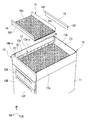
図2は、部品を一部取り外した状態のワゴン装置10を、左前部斜め上方から見た図である。
ワゴン装置10は、デスク装置1の天板3の下方に収納配置可能とされている。ワゴン装置10は、内部に物品収納空間(図示せず)を有するワゴン本体11(什器本体)が略直方体状に形成されている。物品収納空間は、ワゴン本体11の前方側に開口しており、その開口を通してスライド式の引き出し12A,12Bが挿入されている。また、ワゴン本体11の下面には、床面Fに転動可能に載置される図示しないキャスターが取り付けられている。キャスターは、例えば、ワゴン本体11の下面の四隅部等に取り付けられている。
FIG. 2 is a diagram of the
The
ワゴン本体11の上面には、前壁13f、後壁13r、及び、左右の一対の側壁13sを有する平面視略矩形状の上方開口筐体13が固定設置されている。上方開口筐体13は、前壁13fと後壁13rと左右の側壁13sとに囲まれた底壁13bを有するが、上方側は開口されている。上方開口筐体13の前壁13fと後壁13rと左右の側壁13sの各外面は、ワゴン本体11の前面と後面と左右の側面に連続するように形成されている。本実施形態においては、上方開口筐体13がワゴン本体11(什器本体)の上部の物品収納凹部を構成している。
On the upper surface of the
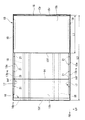
図3は、上方開口筐体13の単体を左前部斜め上方から見た図であり、図4は、上方開口筐体13を上方から見た図である。また、図5は、上方開口筐体13を左側方から見た図であり、図6,図7は、図3のVI−VI線に沿う断面とVII−VII線に沿う断面をそれぞれ示した図である。
上方開口筐体13の内側には、物品を載置するための内部空間を前後に仕切る仕切部材14と、物品を内部上面に載置可能なトレー部材15とが脱着可能に取り付けられている。また、上方開口筐体13は、複数の金属パネルが接合されて基本骨格が構成されている。具体的には、前壁13fと後壁13rと左右の側壁13sと底壁13bとがそれぞれ異なる金属パネルによって構成され、これらの金属パネルの端部が適宜折り曲げられ、溶接等によって相互に接合されている。
FIG. 3 is a view of the single body of the
Inside the
上方開口筐体13の前壁13fには、金属パネルを折り曲げて構成された前部補強部材16が接合されている。前部補強部材16は、前壁13fの上方開口筐体13の内側に臨む上縁部に取り付けられ、前壁13fの左右方向の略全域に亘って延出している。
A front reinforcing
前部補強部材16は、図5,図6に示すように、縦断面が略コ字状の基本断面部16bの一端部と他端部にフランジ部16f−1,16f−2が延設されている。前部補強部材16は、フランジ部16f−1,16f−2を前壁13fの内側面に突き合わせた状態で前壁13fに固定され、それによって前壁13fとの間で矩形断面を形成している。前部補強部材16と前壁13fとによって形成される矩形断面は、前壁13fの左右方向の略全域に亘って延出している。前部補強部材16は、基本断面部16bの上面16b−uが前壁13fの上端面と面一になるように前壁13fに接合されている。
As shown in FIGS. 5 and 6, the
上方開口筐体13の左右の側壁13sには、金属パネルを折り曲げて構成された側部補強部材17が接合されている。側部補強部材17は、側壁13sの上方開口筐体13の内側に臨む部位のうちの、側壁13sの上端部から下方に所定距離離間した部位に取り付けられ、側壁13sの前後方向の略全域に亘って延出している。
A
側部補強部材17は、図7に示すように、縦断面が略コ字状の基本断面部17bの一端部と他端部にフランジ部17f−1,17f−2が延設されている。側部補強部材17は、フランジ部17f−1,17f−2を側壁13sの内側面に突き合わせた状態で側壁13sに固定され、それによって側壁13sとの間の矩形断面を形成している。側部補強部材17と側壁13sとによって形成される矩形断面は、側壁13sの前後方向の略全域に亘って水平に延出してる。側部補強部材17は、基本断面部17bの上面17b−uの高さが側壁13sの略中間高さと合致するように、側壁13sに固定されている。
側部補強部材17は、上面高さが側壁13sの略中間高さと合致するように内側に向かって突出し、かつ、物品収納凹部(上方開口筐体13)の前後方向に連続する内向き突出部を構成している。
As shown in FIG. 7, the
The
また、上方開口筐体13の底壁13bの下面には、金属パネルを折り曲げて構成された一対の底部補強部材18が接合されている。一対の底部補強部材18は、底壁13bの左右方向に離間した位置に前後方向に沿って配置されている。底部補強部材18は、詳細な図示は省力するが縦断面が略コ字状の基本断面部の一端部と他端部に接合用のフランジ部が延設されている。底部補強部材18は、底壁13bの下面との間で矩形断面を形成している。底部補強部材18と底壁13bとによって形成される矩形断面は、底壁13bの前後方向の略全域に亘って延出している。
A pair of
ところで、トレー部材15は、平面視が略矩形状の底壁15bと、底壁15bの前辺から上方に起立する前部壁15fと、底壁15bの後辺から上方に起立する後部壁15rと、を有している。図7に示すように、トレー部材15の高さ寸法H1は、上方開口筐体13の内側の高さ寸法H2よりも短寸に形成されている。また、図4に示すように、トレー部材15の前後方向の寸法L1は、上方開口筐体13の内側の前後寸法L2よりも短寸に形成されている。
なお、トレー部材15の底壁15bや上方開口筐体13の底壁13bの上面には、不織布等の敷布を設置しても良い。
By the way, the
In addition, a non-woven fabric or the like may be placed on the
また、トレー部材15の底壁15bの左右の側辺には、下方側に略L字状に屈曲した脚片19が延設されている。各脚片19には、摺動性の高い部材から成る複数の滑子20が取り付けられている。滑子20は、摺動面が下方を向くように脚片19に取り付けられている。トレー部材15は、上方開口筐体13の内部の左右の側部補強部材17に脱着可能に取り付けられている。本実施形態の場合、トレー部材15は、左右の脚片19が上方開口筐体13内の左右の側部補強部材17の上面17b−uに脱着可能に載置されている。トレー部材15の脚片19は、側部補強部材17の上面17b−uに対して、滑子20を介して摺動可能に当接している。
本実施形態においては、側部補強部材17の上面17b−uが、トレー部材15を支持する支持部を構成している。
Further,
In the present embodiment, the
トレー部材15は、側部補強部材17の上面17b−uに沿わせて適宜前後方向に移動させることにより、上方開口筐体13内における前後方向の位置を変更可能とされている。また、トレー部材15は、側部補強部材17の上面17b−uに支持されることにより、その底壁15bが上方開口筐体13の内部を上下に隔成している。
The
また、左右の各側部補強部材17の基本断面部17bの幅方向内側の壁には、スリット状の挿入開口21が前後方向に離間して複数形成されている。各挿入開口21は、側部補強部材17の基本断面部17bの上部側のコーナ部分から下方に所定長さに亘って形成されている。挿入開口21は、仕切部材14の両端部を左右の側部補強部材17に取り付けるための取付部である。
In addition, a plurality of slit-shaped
仕切部材14は、図2,図3に示すように、金属パネルが適宜折り重ねられ全体が補強されるとともに、長手方向の両端部の上端位置から長手方向の外側に向かって突出する係止フランジ14fが突設されている。仕切部材14は、両端部の係止フランジ14fが、左右の側部補強部材17のいずれかの挿入開口21に嵌入されることによって上方開口筐体13の内側に固定される。
As shown in FIGS. 2 and 3, the
ここで、仕切部材14は、左右の係止フランジ14fが挿入開口21に挿入されることにより、その上面が側部補強部材17の上面17b−uよりも低くなる。したがって、仕切部材14は、左右の側部補強部材17に支持されたトレー部材15の底壁15bよりも下方となる位置において、上方開口筐体13の内部を前後に仕切ることになる。
Here, the upper surface of the
以上のように、本実施形態に係るワゴン装置10(物品収納什器)においては、ワゴン本体11の上部の上方開口筐体13の内部がトレー部材15によって前後方向と上下方向に区画され、トレー部材15の前後方向の位置を変更することによって、トレー部材上の物品収納部の位置を自由に変えることができる。
したがって、本実施形態に係るワゴン装置10を採用した場合には、上方開口筐体13の周壁(前壁13f、後壁13r、及び、左右の側壁13s)によって内部に載置した物品が下方に落下するのを防止できるうえ、上方開口筐体13内のトレー部材15の内側部分と外側部分とに物品を振り分けて、物品を上方開口筐体13の内部に効率良く載置することができる。
As described above, in the wagon device 10 (goods storage device) according to the present embodiment, the inside of the
Therefore, when the
また、トレー部材15は、上方開口筐体13の内部に脱着不能に取り付けることも可能であるが、本実施形態に係るワゴン装置10では、トレー部材15が左右の側部補強部材17の上面17b−uに脱着可能に取り付けられている。このため、上方開口筐体13の内部でトレー部材15を使用しない場合には、トレー部材15を左右の側部補強部材17から取り外すことができる。このため、トレー部材15を取り外すことによって上方開口筐体13の内部を広い空間として利用することができるうえ、取り外したトレー部材15を別の場所で使用することができる。
Further, the
また、本実施形態に係るワゴン装置10は、上方開口筐体13の左右の側壁13sに、上面17b−uの高さが側壁13sの略中間高さ位置と合致するように幅方向内側に突出した側部補強部材17が設けられ、その側部補強部材17の上面17b−uによってトレー部材15が支持されるようになっている。このため、製造の容易な簡単な構成により、トレー部材15を上方開口筐体13内の前後方向の任意の位置に支持させることができる。
Further, the
さらに、本実施形態に係るワゴン装置10においては、上方開口筐体13の左右の側壁13sに突設された側部補強部材17に、仕切部材14を取り付けるための複数の挿入開口21が設けられている。このため、側部補強部材17に支持されるトレー部材15と、上方開口筐体13の内部を前後に仕切る仕切部材14との協働によって、上方開口筐体13の内部を高い自由度をもって様々な空間部に仕切ることができる。したがって、この構成を採用した場合には、上方開口筐体13の内部に物品をより効率良く載置することができる。
Further, in the
特に、本実施形態に係るワゴン装置10の場合、仕切部材14が、側部補強部材17の上面17b−uによって支持されたトレー部材15の底壁15bよりも下方となる位置で、上方開口筐体13の内部を前後に仕切る形状とされている。このため、トレー部材15と仕切部材14の干渉を招くことなく、上方開口筐体13内の下方空間を、仕切部材14によって任意の位置で仕切ることができる。
Particularly, in the case of the
なお、本発明は上記の実施形態に限定されるものではなく、その要旨を逸脱しない範囲で種々の設計変更が可能である。例えば、上記の実施形態においては、物品収納凹部である上方開口筐体13の側壁13sに前後方向に連続する側部補強部材17が取り付けられ、その側部補強部材17の上面17b−uが、トレー部材15を支持する支持部を構成しているが、トレー部材15を支持する支持部はこの構造に限らず、トレー部材15を支持するための専用の支持部材を側壁13sに複数設置するようにしても良い。
また、物品収納凹部である上方開口筐体13の内部に配置する仕切部材14は、トレー部材15の前後方向の移動位置をある程度制限しても良い場合には、上方開口筐体13の内部の高さ寸法とほぼ同寸法の高さに設定しても良い。
さらに、上記の実施形態においては、物品収納什器がキャスターを有するワゴン装置によって構成されているが、物品収納什器は、キャスターを有するワゴン装置に限らず、キャスターを持たず什器本体の内部に物品収納のための空間部を有する什器であっても良い。
The present invention is not limited to the above-described embodiment, and various design changes can be made without departing from the scope of the invention. For example, in the above-described embodiment, the
Further, the partitioning
Further, in the above embodiment, the article storage fixture is configured by a wagon device having a caster, but the article storage fixture is not limited to a wagon device having a caster, and the article storage fixture does not have a caster and stores the articles inside the fixture main body. It may be a furniture having a space portion for.
10 ワゴン装置(物品収納什器)
11 ワゴン本体(什器本体)
13 上方開口筐体(物品収納凹部)
13f 前壁
13r 後壁
13s 側壁
14 仕切部材
15 トレー部材
15b 底壁
17 側部補強部材(上向き突出部)
17b−u 上面(支持部)
21 挿入開口(取付部)
10 Wagon device (goods storage equipment)
11 Wagon body (fixture body)
13 Upper opening housing (container for storing articles)
17b-u upper surface (support portion)
21 Insertion opening (mounting part)
Claims (2)
前記什器本体の上部に設置され、前壁、後壁、及び、左右一対の側壁を有し上方に開口する物品収納凹部と、
前記物品収納凹部の内側に配置され、前記物品収納凹部の内部の高さ寸法よりも短寸かつ、前記物品収納凹部の内部の前後寸法よりも短寸のトレー部材と、を備え、
前記物品収納凹部の左右の各前記側壁には、上面高さが当該側壁の略中間高さ位置と合致するように内側に向かって突出し、かつ、前記物品収納凹部の前後方向に連続する内向き突出部が設けられ、
前記内向き突出部は、前記物品収納凹部の内側を前後に仕切る仕切部材の取付部を有するとともに、上面が前記トレー部材を支持する支持部を構成し、
前記トレー部材は、底壁と、当該底壁の前後辺からそれぞれ上方に起立する前部壁及び後部壁と、前記底壁の左右の側辺から下方に略L字状に屈曲した脚片と、を有するとともに、前後方向に位置変更可能に、かつ、前記底壁が前記物品収納凹部の内部を上下に隔成するように前記内向き突出部の上面に前記脚片で支持され、
前記仕切部材は、前記内向き突出部に支持された前記トレー部材の底壁よりも下方となる位置において、前記物品収納凹部の内側を前後に仕切る形状とされていることを特徴とする物品収納什器。 A furniture main body having an article storage space inside,
An article storage recess which is installed on the upper part of the furniture main body, has a front wall, a rear wall, and a pair of left and right side walls, and which opens upward.
A tray member that is disposed inside the article storage recess and that is shorter than the height dimension inside the article storage recess and that is shorter than the front-rear dimension inside the article storage recess;
Each of the left and right side walls of the article storage recess protrudes inward so that the height of the upper surface of the side wall coincides with a substantially intermediate height position of the side wall, and extends inward in the front-rear direction of the article storage recess. A protrusion is provided,
The inward projecting portion has a mounting portion of a partition member that partitions the inside of the article storage recessed portion into front and back, and an upper surface constitutes a supporting portion that supports the tray member,
The tray member includes a bottom wall, a front wall and a rear wall standing upright from front and rear sides of the bottom wall, and leg pieces bent in a substantially L-shape downward from left and right side edges of the bottom wall. , together with a, supported by longitudinal position changeable in the direction, and the leg piece on the upper surface of the inwardly protruding portions so that the bottom wall is隔成the inside of the article storage recess vertically,
An article storage characterized in that the partition member has a shape that partitions the inside of the article storage recess into front and back at a position below the bottom wall of the tray member supported by the inward projection. Furniture.
Priority Applications (1)
| Application Number | Priority Date | Filing Date | Title |
|---|---|---|---|
| JP2016216690A JP6685881B2 (en) | 2016-11-04 | 2016-11-04 | Article storage fixtures |
Applications Claiming Priority (1)
| Application Number | Priority Date | Filing Date | Title |
|---|---|---|---|
| JP2016216690A JP6685881B2 (en) | 2016-11-04 | 2016-11-04 | Article storage fixtures |
Publications (2)
| Publication Number | Publication Date |
|---|---|
| JP2018068973A JP2018068973A (en) | 2018-05-10 |
| JP6685881B2 true JP6685881B2 (en) | 2020-04-22 |
Family
ID=62113191
Family Applications (1)
| Application Number | Title | Priority Date | Filing Date |
|---|---|---|---|
| JP2016216690A Active JP6685881B2 (en) | 2016-11-04 | 2016-11-04 | Article storage fixtures |
Country Status (1)
| Country | Link |
|---|---|
| JP (1) | JP6685881B2 (en) |
Family Cites Families (10)
| Publication number | Priority date | Publication date | Assignee | Title |
|---|---|---|---|---|
| JPS5764010A (en) * | 1980-09-30 | 1982-04-17 | Matsushita Electric Works Ltd | Cosmetics wagon |
| JPH0192845U (en) * | 1987-12-14 | 1989-06-19 | ||
| JPH0686590U (en) * | 1993-05-28 | 1994-12-20 | ナカガワ家具株式会社 | Household items |
| US5468062A (en) * | 1993-08-04 | 1995-11-21 | Finnegan; Richard J. H. | Double tiered storage trays for a drawer |
| JPH08266351A (en) * | 1995-03-30 | 1996-10-15 | Okamura Corp | Fitting device for vertical partition plate in drawer |
| JP2003024144A (en) * | 2001-07-17 | 2003-01-28 | Kokuyo Co Ltd | Wagon |
| JP4470750B2 (en) * | 2005-02-01 | 2010-06-02 | 株式会社イトーキ | Learning furniture |
| DE202009012917U1 (en) * | 2009-09-26 | 2011-02-10 | Fehre, Jürgen | drawer |
| JP5853322B2 (en) * | 2011-08-11 | 2016-02-09 | コクヨ株式会社 | wagon |
| KR101316014B1 (en) * | 2011-11-10 | 2013-10-18 | 주식회사 일광산업 | Self assembly storage goods for drawer |
-
2016
- 2016-11-04 JP JP2016216690A patent/JP6685881B2/en active Active
Also Published As
| Publication number | Publication date |
|---|---|
| JP2018068973A (en) | 2018-05-10 |
Similar Documents
| Publication | Publication Date | Title |
|---|---|---|
| US8944444B1 (en) | Vertical tool box | |
| KR101454633B1 (en) | Chest of drawers | |
| JP6685881B2 (en) | Article storage fixtures | |
| JP2012217852A (en) | Furniture with at least one sliding door | |
| JP6751334B2 (en) | Wagon equipment | |
| KR200492419Y1 (en) | Receiving device | |
| KR20160044182A (en) | Versatile Kitchen Drawer | |
| JP2532877Y2 (en) | Workbench | |
| JP5284078B2 (en) | Kitchen cabinet drawer | |
| JP6327599B2 (en) | Table system | |
| JP2018183489A (en) | Combination desk | |
| KR102300407B1 (en) | Multi purpose table having storage space | |
| JP2014014453A (en) | Cart apparatus | |
| KR20180043652A (en) | Narrow storage closet for practical space use | |
| JP6794224B2 (en) | Furniture with top plate | |
| JP5578741B2 (en) | Kitchen cabinet drawer | |
| JP5289988B2 (en) | Kitchen cabinet drawer | |
| JP2021065558A (en) | Wagon device and desk set device | |
| KR20230143366A (en) | Storage cabinet for space application of indoor | |
| JP2007097742A (en) | Furniture | |
| JP2023012627A (en) | Desk storage structure and folding desk | |
| JP3180869U (en) | Flat article carrying box | |
| EP1250868A1 (en) | Drop-leaf table particularly for modular kitchens | |
| JP2018183488A (en) | Combination desk | |
| JP2019083913A (en) | Top plate lift type furniture |
Legal Events
| Date | Code | Title | Description |
|---|---|---|---|
| RD03 | Notification of appointment of power of attorney |
Free format text: JAPANESE INTERMEDIATE CODE: A7423 Effective date: 20181012 |
|
| A621 | Written request for application examination |
Free format text: JAPANESE INTERMEDIATE CODE: A621 Effective date: 20190614 |
|
| A131 | Notification of reasons for refusal |
Free format text: JAPANESE INTERMEDIATE CODE: A131 Effective date: 20200107 |
|
| A521 | Request for written amendment filed |
Free format text: JAPANESE INTERMEDIATE CODE: A523 Effective date: 20200306 |
|
| TRDD | Decision of grant or rejection written | ||
| A01 | Written decision to grant a patent or to grant a registration (utility model) |
Free format text: JAPANESE INTERMEDIATE CODE: A01 Effective date: 20200324 |
|
| A61 | First payment of annual fees (during grant procedure) |
Free format text: JAPANESE INTERMEDIATE CODE: A61 Effective date: 20200401 |
|
| R150 | Certificate of patent or registration of utility model |
Ref document number: 6685881 Country of ref document: JP Free format text: JAPANESE INTERMEDIATE CODE: R150 |
|
| R250 | Receipt of annual fees |
Free format text: JAPANESE INTERMEDIATE CODE: R250 |
|
| R250 | Receipt of annual fees |
Free format text: JAPANESE INTERMEDIATE CODE: R250 |