JP2014014453A - Cart apparatus - Google Patents
Cart apparatus Download PDFInfo
- Publication number
- JP2014014453A JP2014014453A JP2012152886A JP2012152886A JP2014014453A JP 2014014453 A JP2014014453 A JP 2014014453A JP 2012152886 A JP2012152886 A JP 2012152886A JP 2012152886 A JP2012152886 A JP 2012152886A JP 2014014453 A JP2014014453 A JP 2014014453A
- Authority
- JP
- Japan
- Prior art keywords
- article
- support
- cart
- locking
- article placement
- Prior art date
- Legal status (The legal status is an assumption and is not a legal conclusion. Google has not performed a legal analysis and makes no representation as to the accuracy of the status listed.)
- Pending
Links
- 238000005452 bending Methods 0.000 description 5
- 230000004308 accommodation Effects 0.000 description 1
- 239000000470 constituent Substances 0.000 description 1
- 229940079593 drug Drugs 0.000 description 1
- 239000003814 drug Substances 0.000 description 1
- 210000003141 lower extremity Anatomy 0.000 description 1
- 238000000034 method Methods 0.000 description 1
- 238000012986 modification Methods 0.000 description 1
- 230000004048 modification Effects 0.000 description 1
- 230000000149 penetrating effect Effects 0.000 description 1
- 238000004904 shortening Methods 0.000 description 1
Images


Abstract
Description
本発明は、カート装置に関するものである。 The present invention relates to a cart apparatus.
周知のように、オフィス、病院、公共施設等における執務空間においては、執務空間内の様々な場所に移動しながら電子機器を用いて執務を行う場合がある。この場合、電子機器の移動にはカート装置を用い、該カート装置の天板上に電子機器を載置して、執務者がカート装置と共に移動し、随時必要に応じた場所にて執務が行われていた。 As is well known, in office spaces such as offices, hospitals, and public facilities, there are cases where offices are used to move to various locations within the office space using electronic devices. In this case, the cart device is used to move the electronic device, the electronic device is placed on the top plate of the cart device, the worker moves with the cart device, and the work is performed at a place as necessary. It was broken.
このようなカート装置としては、下記の特許文献1に記載のものが提案されている。このカート装置は、床面上を走行可能なキャスターが設けられたベースと、該ベースから立設された一対の支柱と、一対の該支柱に支持された天板と、一対の支柱間に設けられたレールと、該レールにスライド可能に支持されたトレーとを備えるものである。
As such a cart apparatus, the thing of the following
また、別のカート装置としては、下記の特許文献2に記載のものも提案されている。このカート装置は、床面上を走行可能なキャスターが設けられたベースと、該ベースから立設され格子状に形成されたフレームと、該フレームに係止されたレールと、該レールにスライド可能に支持されたトレーとを備えるものである。このフレームは、上下方向に離間して配設された複数の横フレームと、左右方向に離間して配設された複数の縦フレームとを有している。 As another cart device, one described in Patent Document 2 below has been proposed. The cart device includes a base provided with casters capable of traveling on a floor surface, a frame standing from the base and formed in a lattice shape, a rail locked to the frame, and a slide on the rail. And a tray supported by the container. This frame has a plurality of horizontal frames that are spaced apart in the vertical direction and a plurality of vertical frames that are spaced apart in the left-right direction.
これらのカート装置によれば、執務者がトレーに必要な物品を収容しながら執務空間を移動して、所望の場所にてトレーに収容された物品を用いて執務をすることが可能である。 According to these cart apparatuses, it is possible for the office worker to move in the office space while accommodating the articles necessary for the tray, and to work using the articles accommodated in the tray at a desired location.
しかしながら、上記の特許文献1に記載のカート装置では、レールが例えばネジ等で支柱に固定されている。よって、執務者が、カート装置の使用態様に応じてレールの上下方向の取付位置を容易に変更することができず、使い勝手が悪いという問題点がある。
However, in the cart apparatus described in
一方、特許文献2に記載のカート装置では、レールを任意の横フレームに係止させることができるため、トレーを任意の位置に設けることができる。しかし、トレーの左右方向には格子状に形成されたフレームが配設されているため、該トレーに収容された物品を左右方向から取り出し、又は左右方向からトレーに物品を収容することができず、使い勝手が悪いという問題点がある。 On the other hand, in the cart device described in Patent Document 2, since the rail can be locked to an arbitrary horizontal frame, the tray can be provided at an arbitrary position. However, since a frame formed in a lattice shape is disposed in the left-right direction of the tray, the articles stored in the tray cannot be taken out from the left-right direction, or the articles cannot be stored in the tray from the left-right direction. There is a problem that it is not easy to use.
本発明は、上記事情に鑑みてなされたものであり、物品を載置する物品載置部の位置を上下方向に容易に変更することができるとともに、該物品載置部へのアクセスを良好とするカート装置を提供するものである。 The present invention has been made in view of the above circumstances, and it is possible to easily change the position of the article placement section on which the article is placed in the vertical direction and to provide good access to the article placement section. A cart device is provided.
上記目的を達成するために、本発明は以下の手段を採用している。
すなわち、本発明に係るカート装置は、床面上を移動する車輪を有するベース体と、該ベース体から立設され、互いに左右方向に離間して配された複数の支持体と、隣り合う少なくともいずれか二つの支持体に支持され、物品を載置可能とされた物品載置部とを備えるカート装置であって、前記物品載置部の前後方向の長さ寸法は、前記支持体の前記前後方向の幅寸法よりも大きく、前記隣り合う二つの支持体又は前記物品載置部のいずれか一方には、係止孔が形成され、前記隣り合う二つの支持体又は前記物品載置部の他方には、前記係止孔に係止される係止部が形成され、前記支持体に形成された前記係止孔又は前記係止部は、上下方向に離間して複数設けられていることを特徴とする。
In order to achieve the above object, the present invention employs the following means.
That is, the cart device according to the present invention includes a base body having wheels that move on the floor surface, and a plurality of support bodies that are erected from the base body and are spaced apart from each other in the left-right direction. A cart device including an article placement unit supported by any two supports and capable of placing an article, wherein the length of the article placement unit in the front-rear direction is the same as that of the support. It is larger than the width dimension in the front-rear direction, and a locking hole is formed in either one of the two adjacent support bodies or the article placement section, and the two adjacent support bodies or the article placement section On the other side, a locking portion to be locked in the locking hole is formed, and a plurality of the locking holes or the locking portions formed in the support body are provided apart in the vertical direction. It is characterized by.
このように構成されたカート装置では、物品載置部に形成された係止部(又は係止孔)を支持体に上下方向に離間して形成された複数の係止孔(又は係止部)のうち一の係止孔(又は係止部)に係止させることで、物品載置部を支持体に設けることができる。また、当該係止を解除して、係止部(又は係止孔)を他の係止孔(又は係止部)に係止させることで、物品載置部を上下方向の別の位置に設けることができる。よって、物品載置部を支持体から取り外して、上下方向の任意の位置に取り付けることを容易に行うことができる。
また、物品載置部の前後方向の長さ寸法が支持体の前後方向の幅寸法よりも大きいため、該物品載置部へ左右方向からアクセスすることができる。よって、物品載置部への物品の載置及び該物品載置部からの物品の取り出しを良好とすることができる。
In the cart device configured as described above, a plurality of locking holes (or locking portions) formed by separating the locking portions (or locking holes) formed in the article placement portion from the support in the vertical direction. ), The article placement portion can be provided on the support. Further, by releasing the locking and locking the locking portion (or locking hole) to another locking hole (or locking portion), the article placement portion is moved to another position in the vertical direction. Can be provided. Therefore, it is possible to easily remove the article placement portion from the support and attach it to an arbitrary position in the vertical direction.
Further, since the length dimension of the article placement portion in the front-rear direction is larger than the width dimension in the front-rear direction of the support, the article placement portion can be accessed from the left-right direction. Therefore, it is possible to satisfactorily place the article on the article placement section and take out the article from the article placement section.
また、本発明に係るカート装置は、前記係止孔及び前記係止部は、前記前後方向に離間して複数形成されていることが好ましい。 In the cart device according to the present invention, it is preferable that a plurality of the locking holes and the locking portions are formed apart from each other in the front-rear direction.
このように構成されたカート装置では、係止部と係止孔とは前後方向に複数係止されるため、支持体は物品載置部に載置された物品を安定的に支持することができる。 In the cart device configured as described above, since the plurality of the locking portions and the locking holes are locked in the front-rear direction, the support can stably support the articles placed on the article placement portion. it can.
また、本発明に係るカート装置は、前記ベース体は、互いに左右方向に離間して配設された複数の脚部材と、複数の前記脚部材を連結する連結部材とを有していてもよい。 In the cart device according to the present invention, the base body may include a plurality of leg members that are spaced apart from each other in the left-right direction and a connecting member that connects the plurality of leg members. .
このように構成されたカート装置では、ベース体は連結部材により連結されているため、カート装置としての剛性を高めることができる。 In the cart apparatus configured as described above, since the base bodies are connected by the connecting member, the rigidity as the cart apparatus can be increased.
また、本発明に係るカート装置は、前記連結部材に取り付けられ、前記物品を支持可能な物品支持板を備えていてもよい。 The cart device according to the present invention may include an article support plate attached to the connecting member and capable of supporting the article.
このように構成されたカート装置では、物品支持板は連結部材に取り付けられているため、ベース体は該物品支持板に載置された物品を安定的に支持することができる。 In the cart apparatus configured as described above, since the article support plate is attached to the connecting member, the base body can stably support the article placed on the article support plate.
また、本発明に係るカート装置は、前記物品支持板の前記前後方向の長さ寸法は、前記連結部材の前記前後方向の幅寸法よりも大きくてもよい。 Moreover, the cart apparatus which concerns on this invention WHEREIN: The length dimension of the said front-back direction of the said article support plate may be larger than the width dimension of the said front-back direction of the said connection member.
このように構成されたカート装置では、物品支持板の前後方向の長さ寸法が連結部材の前後方向の幅寸法よりも大きいため、該物品支持板へ左右方向からアクセスすることができる。よって、物品支持板への物品の載置及び該物品支持板からの物品の取り出しを良好とすることができる。 In the cart apparatus configured as described above, since the length dimension in the front-rear direction of the article support plate is larger than the width dimension in the front-rear direction of the connecting member, the article support plate can be accessed from the left-right direction. Therefore, it is possible to satisfactorily place the article on the article support plate and take out the article from the article support plate.
また、本発明に係るカート装置は、前記物品載置部の前記支持体に対して前方へ突出する長さ寸法と、前記物品載置部の前記支持体に対して後方への突出する長さ寸法とは、異なっていてもよい。 Further, the cart device according to the present invention has a length dimension that projects forward with respect to the support body of the article placement section, and a length that projects backward with respect to the support body of the article placement section. The dimensions may be different.
このように構成されたカート装置では、物品載置部上の空間は、左右方向と前方又は左右方向と後方に開放された空間とされるため、該物品載置部への物品の載置及び該物品載置部からの物品の取り出しを良好とすることができる。 In the cart apparatus configured as described above, the space on the article placement unit is a space opened in the left-right direction and the front or the left-right direction and the rear, so that the placement of the article on the article placement unit and Goods can be taken out from the article placement section.
また、本発明に係るカート装置は、前記支持体としては、互いに前記左右方向に離間して配設された一対の外側支持体と、一対の前記外側支持体の中間に配設された中間支持体とを備え、前記物品載置部は、一対の前記外側支持体のうち一方の前記外側支持体と前記中間支持体との間に設けられた第一物品載置部と、一対の前記外側支持体のうち他方の前記外側支持体と前記中間支持体との間に設けられた第二物品載置部とを有していてもよい。 In the cart device according to the present invention, as the support, a pair of outer supports disposed apart from each other in the left-right direction and an intermediate support disposed between the pair of outer supports. A first article placement section provided between one of the outer support body and the intermediate support body of the pair of outer support bodies, and the pair of outer body sections. You may have the 2nd article mounting part provided between the said other outer side support body and the said intermediate | middle support body among support bodies.
このように構成されたカート装置では、左右方向に第一物品載置部及び第二物品載置部が配設されるため、カート装置に多くの物品を収容することができる。 In the cart apparatus configured as described above, since the first article placement section and the second article placement section are disposed in the left-right direction, many articles can be accommodated in the cart apparatus.
本発明に係るカート装置によれば、物品載置部に形成された係止部(又は係止孔)を支持体に上下方向に離間して形成された係止孔(又は係止部)に係止させ、当該係止を解除することで、物品載置部を支持体に設けることができる。よって、物品を載置する物品載置部の位置を上下方向に容易に変更することができるとともに、該物品載置部への接触を良好とすることができる。 According to the cart device of the present invention, the locking portion (or the locking hole) formed in the article placement portion is formed in the locking hole (or the locking portion) formed to be separated from the support in the vertical direction. By locking and releasing the lock, the article placement portion can be provided on the support. Therefore, the position of the article placement section on which the article is placed can be easily changed in the vertical direction, and the contact with the article placement section can be improved.
(カート装置)
以下、本発明の第一実施形態に係るカート装置について説明する。
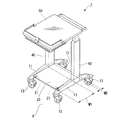
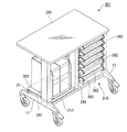
図1に示すように、カート装置1は、床面F上に設けられるベース体10と、該ベース体10から立設された一対の支持体40と、一対の該支持体40に支持された天板50と、一対の該支持体40に支持された物品載置部60とを備えている。
(Cart device)
The cart device according to the first embodiment of the present invention will be described below.
As shown in FIG. 1, the
執務者は、例えば病院等の執務空間において、カート装置1の天板50及び物品載置部60に物品を載置した状態で、天板50に設けられた操作ハンドル51を把持して操作力を与えることで、床面F上でカート装置1を移動させることが可能となっている。
For example, in an office space such as a hospital, the office worker holds an
ここで、執務者が操作ハンドル51と対向するように位置して、操作ハンドル51を押す側となる図1の左奥側をカート装置1の前側とし、操作ハンドル51を引く側となる図1の右手前側をカート装置1の後側とする。また、図1に示す紙面の左手前側から右奥側に向かう方向を左右方向と称する。
Here, the office worker is positioned so as to face the
(ベース体)
ベース体10は、互いに左右方向に離間して前後方向に向かって配設された一対の脚部材11と、一対の該脚部材11を左右方向に連結する連結部材12とを有している。
(Base body)
The
脚部材11の前端及び後端の下面には、床面Fに直交する鉛直軸回りに旋回可能なキャスター(車輪)13がそれぞれ設けられている。このキャスター13により、カート装置1は前後方向及び左右方向に移動可能とされている。
On the lower surfaces of the front end and the rear end of the
連結部材12は脚部材11の前後方向の中央よりも後方に設けられ、この連結部材12の上面には物品を支持可能な物品支持板20が取り付けられている。
The connecting
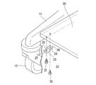
図2及び図3に示すように、物品支持板20は、上面が床面Fと平行な状態となるとともに略矩形状に形成され、連結部材12に取り付けられるとともに、取付部材21を介して脚部材11の前端に取り付けられている。
As shown in FIGS. 2 and 3, the
詳細には、連結部材12には、上下方向に貫通する第一貫通孔12aが、左右方向に離間して複数形成されている。そして、連結部材12の下方から第一ビス31が第一貫通孔12aに挿通され物品支持板20に螺合されることで、物品支持板20は連結部材12に取り付けられている。
Specifically, a plurality of first through
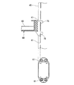
また、図4に示すように、取付部材21は、脚部材11の下面に配設される下壁部22と、該下壁部22から上方に屈曲して形成された屈曲壁部23と、該屈曲壁部23の上端から屈曲して形成され物品支持板20の下面に配設される上壁部24とを有している。この下壁部22と上壁部24とは、屈曲壁部23から反対方向に延出している。
As shown in FIG. 4, the
下壁部22及び上壁部24には、それぞれ上下方向に貫通する第二貫通孔25、第三貫通孔26が穿設されている。そして、下壁部22の下方から第二ビス32が第二貫通孔25に挿通され脚部材11に螺合されるとともに、上壁部24の下方から第三ビス33が第三貫通孔26に挿通され物品支持板20に螺合されることにより、物品支持板20は脚部材11に取り付けられている。
The
図3に示すように、物品支持板20の前後方向の長さ寸法N1は、連結部材12の前後方向の幅寸法N2よりも大きい。また、図2に示すように、物品支持板20の支持体40に対して前方へ突出する長さ寸法M1は、支持体40に対して後方への突出する長さ寸法M2よりも大きい。
As shown in FIG. 3, the longitudinal dimension N1 of the
(支持体)
図1に示すように、支持体40は互いに左右方向に離間した一対で構成され、それぞれの支持体40は脚部材11の前後方向の中央よりも後方から立設されている。
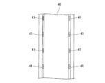
図1、図5及び図6に示すように、支持体40における対向する面、すなわち支持体40の左右方向内側の面には、上下方向に離間して複数の係止孔41が形成されている。この係止孔41は、上下方向に長い長孔であり、前後方向に離間して一対形成されている。また、この係止孔41には、後述する物品載置部60が係止されている。
(Support)
As shown in FIG. 1, the
As shown in FIGS. 1, 5, and 6, a plurality of locking
(天板)
図1に示すように、天板50は、上面が床面Fと平行な状態となるとともに略矩形状に形成され、支持体40に支持されている。そして、上面は薬品等の物品が載置可能であり、又はカルテ等の記載が可能な作業台として使用することができる。この天板50の後側には、操作ハンドル51が設けられている。
(Top board)
As shown in FIG. 1, the
操作ハンドル51は、天板50の後部の左右両側から後方に突設された一対のハンドル取付部51aと、一対の該ハンドル取付部51aを連結するハンドル本体51bとを有している。執務者は、該ハンドル本体51bを把持することで、カート装置1を床面F上に移動させることができる。
The operation handle 51 includes a pair of
また、天板50の上面には、ワイヤー部材52が設けられている。ワイヤー部材52は、線状に形成されたワイヤー本体53と、該ワイヤー本体53を天板50に固定する固定部材54とを有している。
A
ワイヤー本体53は、天板50の上方の前縁に配設される前ワイヤー53aと、該前ワイヤー53aの両端から屈曲して形成された一対の側ワイヤー53bとを有している。
The wire
固定部材54は、前ワイヤー53aの略中央に設けられた前固定部54aと、側ワイヤー53bの端部に設けられた側固定部54bとを有している。前固定部54aは前ワイヤー53aに係合されるとともに下端が天板50に固定され、側固定部54bは側ワイヤー53bに係合されるとともに下端が天板50に固定されている。
The fixing
ワイヤー本体53が固定部材54により天板50に固定されることにより、執務者が操作ハンドル51を把持してカート装置1を移動させても、該天板50に載置された物品の落下が防止される。
Since the wire
(物品載置部)
図1及び図7に示すように、物品載置部60は上下方向に離間して複数設けられ、本実施形態では3個設けられている。この物品載置部60は、支持体40に支持され前後方向に向かって延在する左右一対のレール61と、該レール61に対して前後方向にスライド可能とされ物品を載置可能とされたトレー80とを有している。
この物品載置部60の前後方向の長さ寸法P1は、支持体40の前後方向の幅寸法P2よりも大きい。
(Article placement section)
As shown in FIGS. 1 and 7, a plurality of
The longitudinal dimension P1 of the
レール61は、前後方向に向かって延在するレール本体62と、該レール本体62に設けられた係止体71とを有している。
The
レール本体62は、トレー80が載置されるレール載置部63と、該レール載置部63から立設されたレール立設部64と、該レール立設部64から屈曲して形成されたレール上壁部65とを有している。
The
これらレール載置部63、レール立設部64及びレール上壁部65により囲まれた空間内に、トレー80の左右方向縁部が配設されている。
In the space surrounded by the
係止体71は、レール61のレール立設部64に設けられた係止取付部72と、該係止取付部72に設けられた係止基部73と、該係止基部73の前後方向両端から左右方向外側に向かって屈曲して形成された一対の係止屈曲部74と、一対の該係止屈曲部74の端部に設けられた係止部75とを有している。
The locking
係止部75は、鉤状をなしており、係止屈曲部74の端部に上下方向に離間して一対設けられている。図5に示すように、この係止部75は、トレー80の支持体40の支持される面に形成されており、支持体40に形成された複数の係止孔41のうち任意の係止孔41に係合可能とされている。
The locking
図7に示すように、トレー80は、上方が開放された箱状部材であり、底部をなすトレー底壁部81と、該トレー底壁部81から立設された前後一対のトレー前壁部82及びトレー後壁部83と、該トレー前壁部82とトレー後壁部83とを連結する一対のトレー側壁部84とを有している。このトレー側壁部84が、レール載置部63の上面上を前後方向にスライド可能とされている。
As shown in FIG. 7, the
図1に示すように、レール61の係止部75が支持体40に形成された係止孔41に係止された状態において、物品載置部60の支持体40に対する前方への突出長さQ1は、物品載置部60の支持体40に対する後方への突出長さQ2よりも長い。
As shown in FIG. 1, in the state in which the locking
また、図1に示す状態から、トレー80はレール61に対して前方及び後方のいずれの方向にもスライド可能とされている。
Further, from the state shown in FIG. 1, the
このように構成されたカート装置1では、レール61に形成された係止部75を支持体40に形成された一の係止孔41に係止させ、当該係止を解除して他の係止孔41に係止させることができる。このようにトレー80の取り付け取り外しを、係止部75と係止孔41との係止とその取り外しで行うことができるため、トレー80を支持体40から取り外して、上下方向の任意の位置に取り付けることを容易に行うことができる。
In the
また、トレー80の前後方向の長さ寸法P1が支持体40の前後方向の幅寸法P2よりも大きいため、該トレー80へ左右方向からアクセスすることができる。よって、トレー80への物品の載置及び該トレー80からの物品の取り出しを良好とすることができる。
Further, since the length dimension P1 of the
また、係止部75と係止孔41とは前後方向に一対係止されるため、支持体40はトレー80に載置された物品を安定的に支持することができる。
In addition, since the locking
また、一対の脚部材11は連結部材12により連結されているため、カート装置1としての剛性を高めることができる。
Further, since the pair of
また、物品支持板20は連結部材12及び脚部材11に取り付けられているため、ベース体10は該物品支持板20に載置された物品を安定的に支持することができる。
Further, since the
また、物品支持板20の前後方向の長さ寸法N1が連結部材12の前後方向の幅寸法N2よりも大きいため、該物品支持板20へ左右方向からアクセスすることができる。よって、物品支持板20への物品の載置及び該物品支持板20からの物品の取り出しを良好とすることができる。
Further, since the length dimension N1 in the front-rear direction of the
また、トレー80の上空間は、左右方向及び前方に開放された空間とされるため、該トレー80への物品の載置及びトレー80からの物品の取り出しを良好とすることができる。
Further, since the upper space of the
また、カート装置1の後部には、一対の脚部材11及び連結部材12で囲まれた空間がるため、操作ハンドル51を把持する執務者は下肢をこの空間部分に置くことができ、カート装置1の使い勝手を良好とすることができる。
Further, since there is a space surrounded by the pair of
(第二実施形態)
以下、本発明の第二実施形態に係るカート装置201について、図8を用いて説明する。
この実施形態において、前述した実施形態で用いた部材と同一の部材には同一の符号を付して、その説明を省略する。
(Second embodiment)
Hereinafter, the
In this embodiment, the same members as those used in the above-described embodiment are denoted by the same reference numerals, and the description thereof is omitted.
第一実施形態におけるカート装置1では、一対の該支持体40間に物品載置部60が配設されている。一方、本実施形態におけるカート装置201では、三本の支持体241,242,243間に物品載置部261,262が左右方向に並んで配設されている。
In the
支持体241,242,243としては、左右方向に離間して配設された一対の外側支持体241,242と、一対の該外側支持体241,242の左右方向中央に配設された中間支持体243とを備えている。
The
外側支持体241,242は脚部材11から立設され、中間支持体243は連結部材212の左右方向略中央から立設されている。
The
物品載置部261は、左側に配設された外側支持体241と中間支持体243との間に設けられた第一物品載置部261…と、右側に配設された外側支持体242と中間支持体243との間に設けられた第二物品載置部262…とを有している。
The
第一物品載置部261…、第二物品載置部262…はそれぞれ上下方向に離間して複数設けられ、本実施形態では6個ずつ設けられている。
A plurality of first
このように構成されたカート装置201では、左右方向に第一物品載置部261…及び第二物品載置部262…が配設されるため、カート装置201に多くの物品を収容することができる。よって、カート装置201としての収納力を高めることができ、利便性が高い。
In the
また、カート装置201の左右方向略中央には中間支持体243が設けられているため、カート装置201の左右方向の長さ寸法大きくなった場合でも、その剛性を高めることができる。
Moreover, since the
(第三実施形態)
以下、本発明の第三実施形態に係るカート装置301について、図9を用いて説明する。
この実施形態において、前述した実施形態で用いた部材と共通の部材には同一の符号を付して、その説明を省略する。
(Third embodiment)
Hereinafter, a
In this embodiment, members that are the same as those used in the above-described embodiment are assigned the same reference numerals, and descriptions thereof are omitted.
第二実施形態におけるカート装置201では、三本の支持体241,242,243間に物品載置部261,262が左右方向に並んで配設されている。一方、本実施形態に係るカート装置201では、外側支持体241と中間支持体243との間には物品支持板320が設けられている。
In the
物品支持板320は、その前端が取付部材21を介して脚部材11に固着され、その後端が第一実施形態と同様に下方からビス(不図示)が螺合され連結部材212に固着されている。
The
このように構成されたカート装置301では、物品支持板320の上方が天板350までの上下方向に長い空間とされるため、図9に示すように該空間に高さ寸法の大きい物品を載置することができる。
In the
また、物品支持板320は連結部材212及び脚部材11に固着されているため、ベース体310は該物品支持板320に載置された物品を安定的に支持することができる。
Further, since the
また、このようにカート装置301の左側には高さのある物品を収容し、右側には前後方向にスライド可能とされた物品載置部262…を複数設けることができる。よって、カート装置301としての使い勝手を向上させることができる。
In addition, in this way, a plurality of
また、上述した実施の形態において示した動作手順、あるいは各構成部材の諸形状や組み合わせ等は一例であって、本発明の主旨から逸脱しない範囲において設計要求等に基づき種々変更可能である。 Further, the operation procedure shown in the above-described embodiment, or the shapes and combinations of the constituent members are merely examples, and various modifications can be made based on design requirements and the like without departing from the gist of the present invention.
例えば、上記に示した実施形態では、支持体40に係止孔41が形成され、物品載置部60に係止部75が形成されているが、本構成を逆としてもよい。すなわち、支持体40に上下方向に離間して複数の係止部75が形成され、物品載置部60に係止孔41が形成されていてもよい。
For example, in the embodiment described above, the locking
このような構成でも、係止孔41を支持体40に形成された一の係止部75に係止させ、当該係止を解除して他の係止部75に係止させることができる。このようにトレー80の取り付け取り外しを、係止部75と係止孔41との係止とその取り外しで行うことができるため、トレー80を支持体40から取り外して、上下方向の任意の位置に取り付けることを容易に行うことができる。
Even in such a configuration, the locking
また、物品支持板20、物品載置部60の支持体40に対する前方への突出長さM1,Q1よりも、物品支持板20、物品載置部60の支持体40に対する後方への突出長さM2,Q2の方が長くてもよい。
この場合には、物品載置部60の上空間は、左右方向及び後方に開放された空間とされるため、操作ハンドル51を把持する執務者側である後側に収容空間を設けることができる。
Further, the protruding length M1 and Q1 of the
In this case, since the upper space of the
また、物品載置部60が、板状部材の左右方向端部に係止部75が形成される構成としてもよい。このような場合でも、物品載置部を支持体40から取り外して、上下方向の任意の位置に取り付けることを容易に行うことができる。
In addition, the
また、支持体40が上下方向に伸縮可能な構成であってもよい。この場合には、支持体40を伸張させることで天板50の位置を高くすることができるとともに、上下方向に多くの物品載置部60を設けることができ、カート装置1として利便性と収納力を高めることができる。
Moreover, the
また、係止孔41の上下方向に配設間隔を短くすることで、物品載置部60を上下方向に密に取り付けることができる。
Moreover, the
係止部75と係止孔41の縁部との間に、トレー80の上下移動を規制する部材(不図示)を配設してもよい。
A member (not shown) that restricts the vertical movement of the
1…カート装置
10…ベース体
13…キャスター(車輪)
11…脚部材
12…連結部材
20…物品支持板
40…支持体
41…係止孔
60…物品載置部
75…係止部F…床面
DESCRIPTION OF
DESCRIPTION OF
41 ... Locking
Claims (7)
該ベース体から立設され、互いに左右方向に離間して配された複数の支持体と、
隣り合う少なくともいずれか二つの支持体に支持され、物品を載置可能とされた物品載置部とを備えるカート装置であって、
前記物品載置部の前後方向の長さ寸法は、前記支持体の前記前後方向の幅寸法よりも大きく、
前記隣り合う二つの支持体又は前記物品載置部のいずれか一方には、係止孔が形成され、
前記隣り合う二つの支持体又は前記物品載置部の他方には、前記係止孔に係止される係止部が形成され、
前記支持体に形成された前記係止孔又は前記係止部は、上下方向に離間して複数設けられていることを特徴とするカート装置。 A base body having wheels that move on the floor surface;
A plurality of supports that are erected from the base body and spaced apart from each other in the left-right direction;
A cart device including an article placement unit supported by at least any two adjacent support bodies and capable of placing an article,
The length dimension in the front-rear direction of the article placement portion is larger than the width dimension in the front-rear direction of the support,
A locking hole is formed in either one of the two adjacent supports or the article placement portion,
On the other of the two adjacent support bodies or the article placement portion, a locking portion that is locked to the locking hole is formed,
The cart apparatus according to claim 1, wherein a plurality of the locking holes or the locking portions formed in the support are provided apart from each other in the vertical direction.
前記係止孔及び前記係止部は、前記前後方向に離間して複数形成されていることを特徴とするカート装置。 The cart apparatus according to claim 1, wherein
The cart device according to claim 1, wherein a plurality of the locking holes and the locking portions are formed apart from each other in the front-rear direction.
前記ベース体は、
互いに左右方向に離間して配設された複数の脚部材と、
複数の前記脚部材を連結する連結部材とを有することを特徴とするカート装置。 The cart apparatus according to claim 1 or 2,
The base body is
A plurality of leg members spaced apart from each other in the left-right direction;
A cart device comprising: a connecting member that connects the plurality of leg members.
前記連結部材に取り付けられ、前記物品を支持可能な物品支持板を備えることを特徴とするカート装置。 The cart apparatus according to claim 3,
A cart apparatus comprising an article support plate attached to the connecting member and capable of supporting the article.
前記物品支持板の前記前後方向の長さ寸法は、前記連結部材の前記前後方向の幅寸法よりも大きいことを特徴とするカート装置。 The cart apparatus according to claim 4, wherein
The cart apparatus according to claim 1, wherein a length dimension of the article support plate in the front-rear direction is larger than a width dimension of the connecting member in the front-rear direction.
前記物品載置部の前記支持体に対して前方へ突出する長さ寸法と、前記物品載置部の前記支持体に対して後方への突出する長さ寸法とは、異なっていることを特徴とするカート装置。 The cart apparatus according to any one of claims 1 to 5,
The length dimension of the article placement section projecting forward with respect to the support body and the length dimension of the article placement section projecting rearward with respect to the support body are different. And cart device.
前記支持体としては、互いに前記左右方向に離間して配設された一対の外側支持体と、一対の前記外側支持体の中間に配設された中間支持体とを備え、
前記物品載置部は、一対の前記外側支持体のうち一方の前記外側支持体と前記中間支持体との間に設けられた第一物品載置部と、一対の前記外側支持体のうち他方の前記外側支持体と前記中間支持体との間に設けられた第二物品載置部とを有することを特徴とするカート装置。 The cart apparatus according to any one of claims 1 to 6,
The support includes a pair of outer supports disposed apart from each other in the left-right direction, and an intermediate support disposed between the pair of outer supports,
The article placement section includes a first article placement section provided between one of the outer support bodies and the intermediate support body, and the other of the pair of outer support bodies. A cart apparatus comprising: a second article placement portion provided between the outer support and the intermediate support.
Priority Applications (1)
| Application Number | Priority Date | Filing Date | Title |
|---|---|---|---|
| JP2012152886A JP2014014453A (en) | 2012-07-06 | 2012-07-06 | Cart apparatus |
Applications Claiming Priority (1)
| Application Number | Priority Date | Filing Date | Title |
|---|---|---|---|
| JP2012152886A JP2014014453A (en) | 2012-07-06 | 2012-07-06 | Cart apparatus |
Publications (1)
| Publication Number | Publication Date |
|---|---|
| JP2014014453A true JP2014014453A (en) | 2014-01-30 |
Family
ID=50109728
Family Applications (1)
| Application Number | Title | Priority Date | Filing Date |
|---|---|---|---|
| JP2012152886A Pending JP2014014453A (en) | 2012-07-06 | 2012-07-06 | Cart apparatus |
Country Status (1)
| Country | Link |
|---|---|
| JP (1) | JP2014014453A (en) |
Cited By (2)
| Publication number | Priority date | Publication date | Assignee | Title |
|---|---|---|---|---|
| JP2015211844A (en) * | 2015-05-27 | 2015-11-26 | 株式会社イトーキ | Tray device for nurse cart |
| JP2016019601A (en) * | 2014-07-14 | 2016-02-04 | コクヨファニチャー株式会社 | Transportation fixture |
Citations (6)
| Publication number | Priority date | Publication date | Assignee | Title |
|---|---|---|---|---|
| JPS59184531U (en) * | 1983-05-25 | 1984-12-08 | 松下電工株式会社 | shelving device |
| JP2003061761A (en) * | 2001-08-24 | 2003-03-04 | Yoshiki Minami | Engaging structure between post and bracket of built-up shelf |
| JP2003093450A (en) * | 2001-09-25 | 2003-04-02 | Yuyama Manufacturing Co Ltd | Medicine supplying system |
| JP2005034607A (en) * | 2003-07-01 | 2005-02-10 | Kokuyo Co Ltd | Working table |
| JP2010029632A (en) * | 2008-06-24 | 2010-02-12 | Kokuyo Co Ltd | Rail for tray |
| WO2011004154A1 (en) * | 2009-07-08 | 2011-01-13 | Keymed (Medical & Industrial Equipment) Limited | Shelving system |
-
2012
- 2012-07-06 JP JP2012152886A patent/JP2014014453A/en active Pending
Patent Citations (7)
| Publication number | Priority date | Publication date | Assignee | Title |
|---|---|---|---|---|
| JPS59184531U (en) * | 1983-05-25 | 1984-12-08 | 松下電工株式会社 | shelving device |
| JP2003061761A (en) * | 2001-08-24 | 2003-03-04 | Yoshiki Minami | Engaging structure between post and bracket of built-up shelf |
| JP2003093450A (en) * | 2001-09-25 | 2003-04-02 | Yuyama Manufacturing Co Ltd | Medicine supplying system |
| JP2005034607A (en) * | 2003-07-01 | 2005-02-10 | Kokuyo Co Ltd | Working table |
| JP2010029632A (en) * | 2008-06-24 | 2010-02-12 | Kokuyo Co Ltd | Rail for tray |
| WO2011004154A1 (en) * | 2009-07-08 | 2011-01-13 | Keymed (Medical & Industrial Equipment) Limited | Shelving system |
| JP2012532640A (en) * | 2009-07-08 | 2012-12-20 | キーメッド(メディカル アンド インダストリアル イクイプメント) リミテッド | Shelf system |
Cited By (2)
| Publication number | Priority date | Publication date | Assignee | Title |
|---|---|---|---|---|
| JP2016019601A (en) * | 2014-07-14 | 2016-02-04 | コクヨファニチャー株式会社 | Transportation fixture |
| JP2015211844A (en) * | 2015-05-27 | 2015-11-26 | 株式会社イトーキ | Tray device for nurse cart |
Similar Documents
| Publication | Publication Date | Title |
|---|---|---|
| JP2010105540A (en) | Cart | |
| JP2010279619A5 (en) | ||
| JP2010279619A (en) | Combination furniture of bed and desk | |
| JP6627120B2 (en) | Cart equipment | |
| JP2014014453A (en) | Cart apparatus | |
| JP5975609B2 (en) | Cart equipment | |
| JP2010104573A (en) | Structure for mounting tray and furniture | |
| JP5948166B2 (en) | Cart equipment | |
| JP2014014454A (en) | Tray support structure and cart apparatus including the same | |
| JP2011193998A (en) | Desk with chair accommodating portion | |
| JP6692148B2 (en) | Article placement section and cart device | |
| JP5993631B2 (en) | Cart equipment | |
| JP6627122B2 (en) | Cart equipment | |
| JP6541258B2 (en) | Optional mounting structure and cart device | |
| JP2009017973A (en) | Cart with tray | |
| JP6624420B2 (en) | Display fixtures | |
| JP7434057B2 (en) | cart | |
| JP6327599B2 (en) | Table system | |
| JP7434056B2 (en) | cart | |
| JP2013202407A (en) | Tray device for nurse cart | |
| JP5904631B2 (en) | Floor head unit | |
| JP5957203B2 (en) | Desk equipment | |
| JP7434055B2 (en) | cart | |
| JP4418223B2 (en) | Table with shelf | |
| JP6794224B2 (en) | Furniture with top plate |
Legal Events
| Date | Code | Title | Description |
|---|---|---|---|
| A621 | Written request for application examination |
Free format text: JAPANESE INTERMEDIATE CODE: A621 Effective date: 20150702 |
|
| A977 | Report on retrieval |
Free format text: JAPANESE INTERMEDIATE CODE: A971007 Effective date: 20160428 |
|
| A131 | Notification of reasons for refusal |
Free format text: JAPANESE INTERMEDIATE CODE: A131 Effective date: 20160517 |
|
| A521 | Request for written amendment filed |
Free format text: JAPANESE INTERMEDIATE CODE: A523 Effective date: 20160719 |
|
| A131 | Notification of reasons for refusal |
Free format text: JAPANESE INTERMEDIATE CODE: A131 Effective date: 20170104 |
|
| A521 | Request for written amendment filed |
Free format text: JAPANESE INTERMEDIATE CODE: A523 Effective date: 20170302 |
|
| A02 | Decision of refusal |
Free format text: JAPANESE INTERMEDIATE CODE: A02 Effective date: 20170822 |