JP2010029632A - Rail for tray - Google Patents
Rail for tray Download PDFInfo
- Publication number
- JP2010029632A JP2010029632A JP2008272310A JP2008272310A JP2010029632A JP 2010029632 A JP2010029632 A JP 2010029632A JP 2008272310 A JP2008272310 A JP 2008272310A JP 2008272310 A JP2008272310 A JP 2008272310A JP 2010029632 A JP2010029632 A JP 2010029632A
- Authority
- JP
- Japan
- Prior art keywords
- tray
- vibration control
- rail
- pulled out
- depth direction
- Prior art date
- Legal status (The legal status is an assumption and is not a legal conclusion. Google has not performed a legal analysis and makes no representation as to the accuracy of the status listed.)
- Granted
Links
Images


Landscapes
- Accommodation For Nursing Or Treatment Tables (AREA)
- Drawers Of Furniture (AREA)
Abstract
Description
本発明は、トレーの両側縁部をスライド可能に支持するトレー用レールに関する。 The present invention relates to a tray rail that slidably supports both side edges of a tray.
従来、ナーシングカートや各種ワゴン等、トレーを引き出し可能に支持してなるとともに移動可能である収納家具が種々考えられてきている。このような収納家具においては、トレーの両端部をレールを介してスライド可能に支持する構成が広く知られている(例えば、特許文献1を参照)。
ところで、特許文献1記載の構成では、側方に開口したレールを左右両側端に設け、このレールの開口内にトレーの両端部に設けたフランジを挿入してトレーを支持させている。このような構成では、床面に段差が存在する箇所においてトレーを支持させてなる収納家具を移動させる際、収納家具が振動することがあるが、従来の構成では、トレーをスムーズにスライド移動可能にすべくレールとトレーとの間に隙間を設けているので、収納家具の振動の際にトレーががたつき、振動音が発生する不具合が存在する。
By the way, in the structure of
そこで本発明は上記のような課題に着目したものであり、収納家具の移動の際のトレーのがたつきによる騒音を抑制することを目的としている。 Accordingly, the present invention focuses on the above-described problems, and an object thereof is to suppress noise caused by rattling of the tray when the storage furniture is moved.
すなわち、以上のような課題を解決すべく、本発明に係るトレー用レールは、トレーの両側縁部をスライド可能に支持するトレー用レールであって、トレーに衝き当たった状態で弾性力をトレーに作用させてトレーを保持しトレーの遊動を抑制する制震部材を備えていることを特徴とする。 That is, in order to solve the above-described problems, the tray rail according to the present invention is a tray rail that slidably supports both side edge portions of the tray, and the elastic force is applied to the tray while striking the tray. It is characterized by having a vibration control member that acts on the sway to hold the tray and suppress the movement of the tray.
このようなものであれば、制震部材をトレーに衝き当てると、トレーが弾性力の作用を直接的又は間接的に受けてトレーが保持される。従って、収納家具の移動中に床面に不陸が存在する箇所を通過する際、トレーが衝撃により跳ね上がりレールに衝突して衝突音を発生させることを抑制できる。 In this case, when the damping member is hit against the tray, the tray is directly or indirectly subjected to the action of the elastic force and is held. Therefore, when the storage furniture moves, the tray can be prevented from jumping up due to the impact and colliding with the rail to generate a collision sound when passing through a place where the floor surface is uneven.
前述した課題を解決するにあたり、トレーの引出し作業を円滑に行わせるには、前記制震部材が、弾性変形可能な外周面部を回転可能な状態でトレーに添接させてトレーの遊動を抑制する制震ローラであるものが望ましい。このようなものであれば、引出し作業の際に、制震ローラはトレーに添接した状態で回転するので、トレーと制震ローラとの間の引出し作業の際の摩擦力が不必要に大きくならないからである。 In order to solve the above-described problem, in order to smoothly perform the tray pulling-out operation, the vibration control member is attached to the tray in a state where the outer peripheral surface portion that can be elastically deformed is rotatable, thereby suppressing the floating of the tray. What is a damping roller is desirable. In such a case, since the vibration control roller rotates in contact with the tray during the pulling out operation, the frictional force during the pulling out operation between the tray and the vibration control roller is unnecessarily large. Because it will not be.
このような制震ローラを好適に実現できる態様として、前記制震ローラが、外周面部を構成しトレーに当接した際に弾性変形し弾性力によりトレーを下方に押圧する弾性部と、中心部に位置し硬質材料により構成したコア部とを具備するものが挙げられる。 As a mode in which such a vibration control roller can be suitably realized, the vibration control roller constitutes an outer peripheral surface portion and elastically deforms when it contacts the tray, and an elastic portion that presses the tray downward by elastic force, and a central portion And a core portion made of a hard material.
また、制震部材として制震ローラを有するトレー用レールにおいて、さらに効果的に防音を図ることができるようにするには、前記制震部材として、トレーに当接した際に弾性変形し弾性力によりトレーを下方に押圧する制震ローラと、弾性変形可能な上面部をトレーに添接させてトレーを保持する弾性保持部材とを備えているものが望ましい。このようなものであれば、前記耐震ローラによりトレーを下方に押圧しつつ、この押圧力によりトレーの他の部位を弾性保持部材の上面部に添接させ、これら耐震ローラ及び弾性保持部材によりトレーを挟み込むように保持させることにより、トレーをより安定して保持できるからである。 Further, in order to achieve more effective sound insulation in a rail for a tray having a vibration control roller as a vibration control member, the vibration control member is elastically deformed when it comes into contact with the tray. It is desirable to include a vibration control roller that presses the tray downward by the above and an elastic holding member that holds the tray with an elastically deformable upper surface portion in contact with the tray. In such a case, while pressing the tray downward by the earthquake-resistant roller, the other portion of the tray is brought into contact with the upper surface portion of the elastic holding member by the pressing force, and the tray is moved by the earthquake-resistant roller and the elastic holding member. This is because the tray can be held more stably by being held so as to sandwich it.
前述した課題を解決するにあたり、使用の際の利便性を図るには、前記トレーが奥行き方向両側に引出し可能なものであって、前記制震部材が奥行き方向中央部に位置するものが望ましい。このようなものであれば、トレーを奥行き方向両側に引出し可能にすることによりこのトレーを備えた収納家具を奥行き方向両側から使用できるようにしつつ、前記制震部材を奥行き方向中央部に位置させることにより、トレーを使用せずトレーをこのレールの中央部に位置させる移動時には、制震部材によりトレーを支持させておくことができるからである。 In order to solve the above-described problems, it is desirable that the tray can be pulled out on both sides in the depth direction and the vibration control member is located in the center in the depth direction in order to improve the convenience in use. In such a case, by allowing the tray to be pulled out to both sides in the depth direction, the storage furniture including the tray can be used from both sides in the depth direction, and the vibration control member is positioned in the center in the depth direction. This is because the tray can be supported by the vibration control member when moving the tray to the central portion of the rail without using the tray.
特に、前記制震部材を奥行き方向両端部にも配しているものであれば、奥行き方向中央部の制震部材によりトレーの奥行き方向中央部を支持させるだけでなく、前記奥行き方向両端部の制震部材によりトレーの奥行き方向両端部も支持させることができるので、トレーをより安定して保持でき、トレーのがたつきによる衝突音の発生をさらに効果的に防ぐことができる。 In particular, if the vibration control members are also arranged at both ends in the depth direction, not only the central portions in the depth direction of the tray are supported by the vibration control members in the central portions in the depth direction, but also Since both ends of the tray in the depth direction can be supported by the vibration control member, the tray can be held more stably, and the occurrence of a collision sound due to rattling of the tray can be more effectively prevented.
さらに、トレーの引出し時にトレーの上方への抜脱をより確実に図るには、トレーの上動を規制する上壁を有するとともに、前記上壁の一部に切り欠き孔を有し、この切り欠き孔の上下両側に跨る位置に前記制震ローラを設けているものが望ましい。このようなものであれば、トレーの非使用時には制震ローラにトレーを保持させつつ、トレーを引き出す際にはトレーの上方に前記上壁が位置するようにできるからである。 Furthermore, in order to more reliably pull out the tray when the tray is pulled out, the tray has an upper wall that regulates the upward movement of the tray, and has a notch hole in a part of the upper wall. What provided the said damping roller in the position straddling the up-and-down both sides of a notch hole is desirable. This is because the upper wall can be positioned above the tray when the tray is pulled out while the vibration control roller holds the tray when the tray is not used.
そして、トレーの抜け止めを確実に図るには、水平姿勢で引き出されるトレーと係わり合うことにより該トレーの抜出を阻止する第1の抜出阻止部と、手前を持ち上げた姿勢で引き出されるトレーを係止して該トレーの抜出を阻止する第2の抜出阻止部とを具備してなるものが望ましい。このようなものであれば、水平姿勢及び手前を持ち上げた姿勢のいずれの姿勢でトレーを引き出した場合であっても、前記第1又は第2の抜出阻止部のいずれかが機能するからである。 In order to reliably prevent the tray from being removed, the tray is pulled out in a posture in which the first pull-out prevention portion that prevents the tray from being pulled out by engaging with the tray pulled out in a horizontal posture and the posture in which the front is lifted up. It is desirable to include a second extraction preventing portion that locks the tray and prevents the tray from being extracted. If this is the case, either the first or second extraction preventing portion functions even when the tray is pulled out in either the horizontal posture or the posture in which the front is lifted. is there.
本発明によれば、トレーを収納した状態で制震部材をトレーに衝き当てると、トレーが弾性力の作用を直接的又は間接的に受けて保持されるので、収納家具の移動中に床面に不陸が存在する箇所を通過する際、トレーが衝撃により跳ね上がりレールに衝突して衝突音を発生させることを抑制できる。すなわち、収納家具の移動の際のトレーのがたつきによる騒音の発生を抑制できる。 According to the present invention, when the damping member is struck against the tray in the state in which the tray is stored, the tray is directly or indirectly subjected to the action of the elastic force, so that the floor surface is moved during the movement of the storage furniture. When passing through a place where unevenness exists, it is possible to suppress the tray from jumping up due to an impact and colliding with the rail to generate a collision sound. That is, it is possible to suppress the generation of noise due to the rattling of the tray when the storage furniture is moved.
以下、本発明の実施の第一の形態を、図面を参照して説明する。 Hereinafter, a first embodiment of the present invention will be described with reference to the drawings.
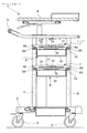
本実施形態に係る収納家具たるナーシングカート1は、医療施設内等で用いられるナーシングカートとして周知のものと略同様の構成を有する。すなわち、このナーシングカート1は、全体斜視図を図1、中央縦断面図を図2にそれぞれ示すように、キャスタ2と、下面に前記キャスタ2を取り付けてなる底版3と、この底版3の後部から左右1対に起立させてなる後支柱4と、前記底版3の前部から左右1対に起立させてなる前支柱5と、前記後支柱4のうち1つに昇降可能に支持させてなる天板6と、この天板6の下方において前記後支柱4及び前支柱5に支持させて左右に対をなして設けたレール7と、このレール7に左右両側端部を奥行き方向にスライド可能に支持されるトレー8と、前記後支柱4、4の上端から後方に延伸させて設けた把持部9とを具備する。
The
ここで、前記トレー8は、図1ないし図6に示すように、平面視略矩形状をなし、内部に収納空間を有するトレー本体81と、このトレー本体81の上縁部から外方に延伸させて設けた鍔部82と、この鍔部82の外側縁から垂下させて設けた垂下壁83とを具備する。この垂下壁83のうち、このトレー8の側端部に位置するものを側垂下壁83a、前後両端部に位置するものを後垂下壁83bとそれぞれ称する。これら側垂下壁83a及び後垂下壁83bを区別せず総称する場合は単に「垂下壁83」と称する。そして、左右両側縁部の垂下壁83aを前記レール7に支持させている。
Here, as shown in FIGS. 1 to 6, the
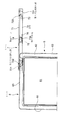
一方、前記レール7は、図1ないし図6に示すように、前記後支柱4及び前支柱5に高さ位置を変更可能に支持されている。より具体的には、前記後支柱4及び前支柱5に複数のレール支持孔4a、5aを高さ方向に離間させて設けているとともに、このレール支持孔4a、5aに取り付けたレール支持具70にレール7を支持させるようにしている。
On the other hand, the
また、このレール7は、前記レール支持具を介して前記後支柱4及び前支柱5に支持させてなる側壁71と、この側壁71の下端部から水平かつナーシングカート1の幅方向中央に向かう方向に延伸させて設けた底壁72と、前記側壁71の上部から水平かつナーシングカート1の幅方向中央に向かう方向に延伸させて設けてなるとともに奥行き方向中央部に切り欠き孔73aを有する上壁73とを具備する。
The
しかして本実施形態では、前記レール7は、弾性変形可能な外周面部を回転可能な状態でトレー8に添接させてトレー8の遊動を抑制する制震部材たる制震ローラ74をさらに具備する。より具体的には、この制震ローラ74は、前記上壁73の切り欠き孔73aの上下両側に跨る位置に設けていて、前記側壁71から法線方向に延伸させて設けた軸75に支持させている。なお、本実施形態では、上壁73奥行き方向中央部の内側縁からローラ支持壁76を起立させて設けていて、軸75の側壁71と反対側をこのローラ支持壁76に支持させている。また、この制震ローラ74は、外周面部を構成しトレー8に当接した際に弾性変形し弾性力によりトレー8を下方に押圧する弾性部741と、中心部に位置し硬質材料により構成したコア部742とを具備する。前記弾性部741は、例えばエラストマー樹脂や、天然ゴムや、合成ゴム等により形成している。一方、前記コア部742は、例えばポリオキシメチレン樹脂により形成している。そして、前記軸75はこのコア部742の両側に突出している。
Thus, in this embodiment, the
そして、トレー8を奥行き方向中央部に位置させた状態では、この制震ローラ74は弾性変形した状態でトレー8の鍔部82に当接している。具体的には、前記弾性部741は、具体的にはトレー8の鍔部82の上面82aに当接する。その際、この弾性部741は弾性変形し、弾性力によりトレー8を底壁72に向けて押し付けつつ、トレー8を保持する。すなわち、このトレー8は制震ローラ74により上方への移動を規制され、奥行き方向中央部に弾性保持される。
When the
一方、このトレー8が引き出されると、制震ローラ74はトレー8との摩擦力を受けて回転する。そして、このトレー8の引出し方向と反対側の端部が制震ローラ74よりも引出し方向側に達した際には、このトレー8の鍔部82の上方にはレールの上壁73が存在し、この上壁73がトレー8の上方への抜出を引き続き規制する。
On the other hand, when the
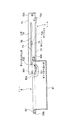
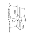
さらに、このレール7の底壁72には、水平姿勢で引き出されるトレー8と係わり合うことにより該トレー8の抜出を阻止する第1の抜出阻止部721と、手前を持ち上げた姿勢で引き出されるトレー8を係止して該トレー8の抜出を阻止する第2の抜出阻止部722とを具備させている。
Further, the
前記第1の抜出阻止部721は、底壁72の奥行き方向両端に設けてなり、図5に示すように、水平姿勢で引き出されるトレー8の前記側垂下壁83aに設けた抜け止め爪831と係わり合うことにより、該トレー8の抜出を阻止する。
The first
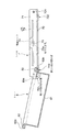
前記第2の抜出阻止部722は、図7に示すように、底壁72の奥行き方向中央から端部に向かうにつれ下降する傾斜部722aと、前記底壁72の側壁71側半分においてこの傾斜部722aの終端から水平に延伸させて設けた側垂下壁収納部722bと、この側垂下壁収納部722bの終端から起立させて設けた第1起立壁722cと、前記底壁72の他方側半分において前記傾斜部722aの終端から水平に延伸させて設けてなり前記側垂下壁収納部722bよりも長手寸法が小さい後垂下壁収納部722dと、この後垂下壁収納部722dの終端から起立させて設けた第2起立壁722eとを具備する。そして、トレー8を手前を持ち上げた姿勢で引き出された際に、図6に示すように、左右の側垂下壁83aが側垂下壁収納部722b内に位置した状態で、後垂下壁83bが第2起立壁722eに当接して該トレー8の抜出を阻止する。
As shown in FIG. 7, the second
以上のような構成とすることにより、本実施形態に係るレール7は、弾性変形可能な外周面部すなわち弾性部741を回転可能な状態でトレー8に添接させてトレー8の遊動を抑制する制震ローラ74を備えているので、この制震ローラ74の外周面部をトレー8に添接させると、前記弾性部741が弾性変形してトレー8を保持する作用を与える。従って、ナーシングカート1の移動中に床面に不陸が存在する箇所を通過する際、トレー8が衝撃により跳ね上がりレール7に衝突して衝突音を発生させることを抑制できる。すなわち、ナーシングカート1の移動の際のトレー8のがたつきによる騒音を抑制できる。さらに、この制震ローラ74は、引出し作業の際に、トレー8に添接した状態で回転するので、トレー8と制震ローラ74との間の引出し作業の際の摩擦力が不必要に大きくならず、トレー8の引出し作業を円滑に行うことができる。さらに、ローラ74の前記弾性部741が弾性変形してトレー8を保持する態様を採用しているので、弾性力を付与するための特別な部材を他に必要とせず、部品点数の削減及び構造の簡単化を図ることもできる。
With the configuration as described above, the
また、前記トレー8が奥行き方向両側に引出し可能で、かつ前記制震ローラ74が奥行き方向中央部に位置するので、トレー8を奥行き方向両側に引出し可能にすることによりこのトレー8を奥行き方向両側から使用できるようにしつつ、トレー8を使用せずトレー8をこのレール7の中央部に位置させる移動時には、制震ローラ74によりトレー8を支持させておくことができる。
Further, since the
さらに、トレー8の上動を規制する上壁73を有するとともに、前記上壁73の一部に切り欠き孔73aを有し、この切り欠き孔73aの上下両側に跨る位置に前記制震ローラ74を設けているので、トレー8の非使用時には制震ローラ74にトレー8を保持させつつ、トレー8を引き出す際にはトレー8の上方に前記上壁73が位置するようにできる。従って、トレー8の引出し時にトレー8の上方への抜脱の阻止をより確実に図ることができる。
Furthermore, the
さらに、前記制震ローラ74が、外周面部を構成しトレー8に当接した際に弾性変形し弾性力によりトレー8を下方に押圧する弾性部741と、中心部に位置し硬質材料により構成したコア部742とを具備するので、弾性部741をトレー8に当接させて弾性変形させトレー8を弾性保持しつつ、コア部742は硬質材料により構成してこの制震ローラ74の回転をスムーズに行わせることができる。
Further, the
そして、水平姿勢で引き出されるトレー8と係わり合うことにより該トレー8の抜出を阻止する第1の抜出阻止部721と、手前を持ち上げた姿勢で引き出されるトレー8を係止して該トレー8の抜出を阻止する第2の抜出阻止部722とを具備してなるので、水平姿勢及び手前を持ち上げた姿勢のいずれの姿勢でトレー8を引き出した場合であっても、前記第1又は第2の抜出阻止部722のいずれかが機能し、トレー8の抜け止めを確実に図ることができる。
Then, the
次いで、本発明の実施の第二の形態について以下に述べる。なお、上述した第一の実施形態に係るものに対応する部位には、同一の名称及び符号を付している。 Next, a second embodiment of the present invention will be described below. In addition, the same name and code | symbol are attached | subjected to the site | part corresponding to what concerns on 1st embodiment mentioned above.
本実施形態に係る収納家具たるナーシングカートA1は、中央縦断面図を図8に示すように、キャスタ2と、下面に前記キャスタ2を取り付けてなる底版3と、この底版3の後部から左右1対に起立させてなる後支柱4と、前記底版3の前部から左右1対に起立させてなる前支柱5と、前記後支柱4のうち1つに昇降可能に支持させてなる天板6と、この天板6の下方において前記後支柱4及び前支柱5に支持させて左右に対をなして設けたレールA7と、このレールA7に左右両側端部を奥行き方向にスライド可能に支持されるトレー8と、前記後支柱4、4の上端から後方に延伸させて設けた把持部9とを具備する。ここで、レールA7以外は、前述した第一の実施形態に係るものと同様の構成を有するので、詳細な説明は省略する。ここで、レールA7の構成を以下に述べる。
As shown in FIG. 8, the nursing cart A <b> 1 that is a storage furniture according to the present embodiment has a
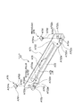
前記レール7は、図9に示すように、前記後支柱4及び前支柱5に高さ位置を変更可能に支持されている。より具体的には、前記後支柱4及び前支柱5に複数のレール支持孔4a、5aを高さ方向に離間させて設けているとともに、このレール支持孔4a、5aに取り付けたレール支持具A70にレールA7を支持させるようにしている。
As shown in FIG. 9, the
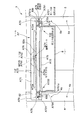
また、このレールA7は、図9及び図10に示すように、前記レール支持具A70を介して前記後支柱4及び前支柱5に支持させてなる側壁A71と、この側壁A71の下端部から水平かつナーシングカート1の幅方向中央に向かう方向に延伸させて設けた底壁A72と、前記側壁A71の上部から水平かつナーシングカート1の幅方向中央に向かう方向に延伸させて設けてなるとともに奥行き方向中央部に切り欠き孔A73aを有する上壁A73とを具備する。
Further, as shown in FIG. 9 and FIG. 10, the rail A7 has a side wall A71 supported by the
さらに、このレールA7の底壁A72には、水平姿勢で引き出されるトレー8と係わり合うことにより該トレー8の抜出を阻止する第1の抜出阻止部A721と、手前を持ち上げた姿勢で引き出されるトレー8を係止して該トレー8の抜出を阻止する第2の抜出阻止部A722とを具備させている。
Further, the bottom wall A72 of the rail A7 is pulled out in a posture in which a first extraction preventing portion A721 that prevents the
前記第1の抜出阻止部A721は、前述した第1実施形態における第1の抜出阻止部721と同様の構成を有する。すなわち、底壁A72の奥行き方向両端に設けてなり、水平姿勢で引き出されるトレー8の前記側垂下壁83aに設けた抜け止め爪831と係わり合うことにより、該トレー8の抜出を阻止する。
The first extraction preventing portion A721 has the same configuration as the first
前記第2の抜出阻止部A722も、前述した第1実施形態における第2の抜出阻止部722と同様の構成を有する。すなわち、図10及び図12に示すように、底壁A72の奥行き方向中央から端部に向かうにつれ下降する傾斜部A722aと、前記底壁A72の側壁A71側半分においてこの傾斜部A722aの終端から水平に延伸させて設けた側垂下壁収納部A722bと、この側垂下壁収納部A722bの終端から起立させて設けた第1起立壁A722cと、前記底壁A72の他方側半分において前記傾斜部A722aの終端から水平に延伸させて設けてなり前記側垂下壁収納部A722bよりも長手寸法が小さい後垂下壁収納部A722dと、この後垂下壁収納部A722dの終端から起立させて設けた第2起立壁A722eとを具備する。そして、トレー8を手前を持ち上げた姿勢で引き出された際に、左右の側垂下壁83aが側垂下壁収納部A722b内に位置した状態で、後垂下壁83bが第2起立壁A722eに当接して該トレー8の抜出を阻止する。
The second extraction preventing part A722 also has the same configuration as the second
また、前記レールA7は、上述した第一の実施形態に係るレール7と同様に、弾性変形可能な外周面部を回転可能な状態でトレー8に添接させてトレー8の遊動を抑制する制震部材たる制震ローラA74をさらに具備する。より具体的には、この制震ローラA74は、前記図9に示すように、前記上壁A73の切り欠き孔A73aの上下両側に跨る位置に設けていて、前記側壁A71から法線方向に延伸させて設けた軸A75に支持させている。なお、本実施形態では、上壁A73の奥行き方向中央部の内側縁からローラ支持壁A76を起立させて設けていて、軸A75の側壁A71と反対側をこのローラ支持壁A76に支持させている。また、この制震ローラA74は、外周面部を構成しトレー8に当接した際に弾性変形し弾性力によりトレー8を下方に押圧する弾性部A741と、中心部に位置し硬質材料により構成したコア部A742とを具備する。前記弾性部A741は、例えばエラストマー樹脂や、天然ゴムや、合成ゴム等により形成している。一方、前記コア部A742は、例えばポリオキシメチレン樹脂により形成している。そして、前記軸A75はこのコア部A742の両側に突出している。
In addition, the rail A7, like the
しかして、本実施形態に係るナーシングカートA1のレールA7は、前記図9及び図10に示すように、制震部材として、前記制震ローラA74の他に、弾性変形可能な上面部をトレーに添接させてトレーを保持する弾性保持部材A79をさらに具備する。 Thus, the rail A7 of the nursing cart A1 according to the present embodiment has, as shown in FIG. 9 and FIG. An elastic holding member A79 that holds the tray in contact is further provided.
具体的には、前記弾性保持部材A79は、前記図9、図10、図11、及び図12に示すように、前記底壁A72に形成した凹部A72x内に嵌め合わせてなるとともに、例えばエラストマー樹脂や、天然ゴムや、合成ゴム等により形成した部材である。さらに詳述すると、この弾性保持部材A79は、前記凹部A72x内に収納してなる弾性保持部材本体A791と、この弾性保持部材本体A791から下方に突出し前記凹部A72xの底面に設けた挿通孔A72yを通過させてなる接続部A792と、この接続部A792の先端部に設けてなり前記挿通孔A72yの開口縁部に係り合わせてなる抜け止め部A793とを有する。この弾性保持部材A79は、前記抜け止め部A793を弾性変形させつつ前記挿通孔A72yを上方から下方に通過させることによりレールA7の底壁A72に取り付けるようにしている。また、この弾性保持部材A79の上面、すなわち前記弾性保持部材本体A791の上面A791aの少なくとも一部は、この弾性保持部材A791を設けた部位に隣接する部位の底壁A72の上面A72aよりも上方に突出させている。 Specifically, as shown in FIGS. 9, 10, 11, and 12, the elastic holding member A79 is fitted into a recess A72x formed in the bottom wall A72, for example, an elastomer resin. Or a member formed of natural rubber, synthetic rubber or the like. More specifically, the elastic holding member A79 has an elastic holding member main body A791 housed in the concave portion A72x, and an insertion hole A72y that protrudes downward from the elastic holding member main body A791 and is provided on the bottom surface of the concave portion A72x. It has a connecting portion A792 that is allowed to pass through, and a retaining portion A793 that is provided at the tip of the connecting portion A792 and is engaged with the opening edge of the insertion hole A72y. The elastic holding member A79 is attached to the bottom wall A72 of the rail A7 by passing the insertion hole A72y downward from above while elastically deforming the retaining portion A793. Further, the upper surface of the elastic holding member A79, that is, at least a part of the upper surface A791a of the elastic holding member main body A791 is located above the upper surface A72a of the bottom wall A72 adjacent to the portion where the elastic holding member A791 is provided. It is protruding.
そして、トレー8を奥行き方向中央部に位置させた状態では、前記図9及び図11に示すように、前記制震ローラA74は弾性変形した状態でトレー8の鍔部82に当接している。具体的には、前記弾性部A741は、トレー8の鍔部82の上面82aに当接する。その際、この弾性部A741は弾性変形し、弾性力によりトレー8を底壁A72に向けて押し付けつつ、トレー8を保持する。すなわち、このトレー8は制震ローラA74により上方への移動を規制され、奥行き方向中央部に弾性保持される。一方、トレー8の前後両端部では、このトレー8の鍔部82の下端が前記弾性保持部材A792に添接しているので、前記弾性力により前記鍔部82が弾性保持部材A79に押し付けられるが、その際、前記弾性保持部材A79が弾性変形し、前記トレー8の鍔部82は上方に向かう作用を受ける。すなわち、前記制震ローラA74と前記弾性保持部材A79とによりトレー8を挟み込むように保持する。
When the
本実施形態に係る構成によれば、上述した第一の実施形態に係る椅子の構成に係る効果に加え、以下に述べるような効果が得られる。 According to the structure which concerns on this embodiment, in addition to the effect which concerns on the structure of the chair which concerns on 1st embodiment mentioned above, the effect as described below is acquired.
すなわち、制震部材として、トレー8に当接した際に弾性変形し弾性力によりトレー8を下方に押圧する制震ローラA74と、弾性変形可能な上面部A791aをトレー8に添接させてトレー8を保持する弾性保持部材A79とを備えているので、前記耐震ローラA74によりトレー8の奥行き方向中央部を下方に押圧しつつ、この押圧力によりトレー8の奥行き方向両端部を弾性保持部材A79の上面部に添接させ、これら耐震ローラA74及び弾性保持部材A79によりトレー8を挟み込むように保持させることにより、トレー8をより安定して保持できるとともに、トレー8のがたつきによる衝突音の発生をさらに効果的に防ぐことができる。
That is, as a vibration control member, a vibration control roller A74 that elastically deforms when pressed against the
また、この弾性保持部材A79の上面A791aの少なくとも一部を、この弾性保持部材A791を設けた部位に隣接する部位の底壁A72の上面A72aよりも上方に突出させているので、トレー8を奥行き方向に移動させると鍔部82の下端がこの弾性保持部材A791に接触し、従って、より確実に鍔部82の下端をこの弾性保持部材A791に添接させ、この弾性保持部材A791及び前記耐震ローラA74によりトレー8をより確実に保持させることができる。
Further, since at least a part of the upper surface A791a of the elastic holding member A79 protrudes above the upper surface A72a of the bottom wall A72 at a portion adjacent to the portion where the elastic holding member A791 is provided, the
なお、本発明は以上に述べた実施形態に限られない。 The present invention is not limited to the embodiment described above.
例えば、ナーシングカートに限らず、オフィスや店舗等で用いられ、トレーを引き出し可能なワゴンのトレーをスライド可能に支持するトレー用レールに上述したような構成を採用してもよい。 For example, the above-described configuration may be adopted not only in the nursing cart but also in a tray rail that is slidably supported on a wagon tray that is used in an office or a store and can be pulled out.
また、制震ローラの中心部に硬質材料により形成したコア部を設ける代わりに、円盤状をなす制震ローラの全体を弾性変形可能な軟質材料により形成し、その中心部に軸を挿し通すようにしてもよい。 Also, instead of providing a core made of a hard material at the center of the vibration control roller, the entire disk-shaped vibration control roller is made of an elastically deformable soft material, and the shaft is inserted through the center. It may be.
さらに、上壁に切り欠きを設けてこの切り欠きの上下両側に跨る位置に制震ローラを設ける代わりに、上壁を奥行き方向に離間させて複数箇所に設け、上壁と上壁との間に制震ローラを設ける態様を採用してもよい。 In addition, instead of providing notches on the upper wall and providing vibration control rollers at positions straddling the upper and lower sides of the notch, the upper wall is provided in multiple locations spaced apart in the depth direction, and between the upper wall and the upper wall. A mode in which a vibration control roller is provided may be adopted.
加えて、トレーが奥行き方向両側に引出し可能に支持するレールに限らず、トレーを一方向にのみ引出し可能に支持するレールに本発明を適用してもよい。この場合、制震ローラは引出し操作の際に操作者に向かう方向と反対側の端部ないしその近傍に設けると、引出し操作を行わない移動時にはトレーのがたつきを抑えることができ、トレーの引出し操作時には引出し操作をスムーズに行うようにできる。 In addition, the present invention may be applied not only to the rail that supports the tray so that it can be pulled out in both sides in the depth direction, but also to the rail that supports the tray so that it can be pulled out only in one direction. In this case, if the vibration control roller is provided at the end opposite to the direction toward the operator during the drawer operation or in the vicinity thereof, the rattling of the tray can be suppressed during movement when the drawer operation is not performed. The drawer operation can be performed smoothly during the drawer operation.
また、上述した実施形態では、制震部材として弾性変形可能な外周面部を回転可能な状態でトレーに添接させてトレーの遊動を抑制する制震ローラを採用しているが、トレーに衝き当たった状態で弾性力をトレーに作用させてトレーを保持可能なものであれば他の態様を採用してもよい。例えば、回転軸周りに回転可能な制震部材本体たるローラと、このローラの回転軸とレールとの間を接続するばねとを具備する制震部材を利用してもよい。このような制震部材を採用しても、回転軸がばねから受ける弾性力により、ローラをトレーに押し当てた状態でトレーに添接させてこのトレーを保持できるので、このローラを利用してトレーの遊動を抑制できる。この場合、ローラの材質は硬質のものであっても軟質のものであってもかまわない。また、このような態様であっても、引出し作業の際に、トレーに添接した状態で回転するので、トレーと制震ローラとの間の引出し作業の際の摩擦力が不必要に大きくならず、トレーの引出し作業を円滑に行うことができる。さらに、制震部材はローラを用いる必要もなく、トレーに衝き当たることが可能な制震部材本体と、この制震部材本体とレールとの間を接続するばねとを具備する制震部材を利用してもよい。この場合も、制震部材本体の材質は硬質のものであっても軟質のものであってもかまわない。このような制震部材を採用しても、制震部材本体がばねから受ける弾性力により、制震部材本体をトレーに押し当てた状態でトレーに添接させてこのトレーを保持し、このトレーの遊動を抑制できる。なお、制震部材本体がローラでない場合、制震部材本体のトレーに添接する側の表面にトレーとの間の摩擦係数を小さくする滑り加工を施したもの、具体的には硬質材料により構成し該表面を平滑化加工したもの、又は制震部材本体のトレーに添接する側の表面に摩擦係数が小さな材料により構成した層をこのような材料により構成したテープの貼付やこのような材料によるコーティング等により形成したものであれば、トレーと制震ローラとの間の引出し作業の際の摩擦力が不必要に大きくならず、トレーの引出し作業を円滑に行うことができる。 Further, in the above-described embodiment, the vibration control roller that suppresses the loose movement of the tray by contacting the tray with the elastically deformable outer peripheral surface portion being rotatable is adopted as the vibration control member. Other modes may be adopted as long as the tray can be held by applying an elastic force to the tray in a state of being in contact. For example, you may utilize the damping member provided with the roller which is a damping member main body rotatable around a rotating shaft, and the spring which connects between the rotating shaft of this roller, and a rail. Even if such a damping member is used, the elastic force received by the rotating shaft from the spring can hold the tray by pressing the roller against the tray and holding the tray. Tray movement can be suppressed. In this case, the material of the roller may be hard or soft. Even in such a mode, since it rotates while being attached to the tray at the time of the drawing operation, the frictional force at the time of the drawing operation between the tray and the vibration control roller is unnecessarily large. Therefore, the tray can be drawn out smoothly. Furthermore, the damping member does not need to use a roller, and a damping member comprising a damping member body capable of hitting the tray and a spring connecting the damping member body and the rail is used. May be. Also in this case, the material of the damping member main body may be hard or soft. Even if such a vibration control member is used, the elastic member receives the elastic member from the spring so that the vibration control member body is pressed against the tray and held in contact with the tray. Can be suppressed. If the damping member body is not a roller, the surface of the damping member body on the side that comes into contact with the tray has been subjected to a sliding process that reduces the coefficient of friction between the tray, specifically, a hard material. The surface of the surface of the vibration control member main body that is smoothed or the surface of the damping member body that is in contact with the tray is coated with a tape made of such a material or coated with such a material. If it is formed by the above, the frictional force during the drawing operation between the tray and the vibration control roller is not unnecessarily increased, and the tray drawing operation can be performed smoothly.
そして、第2の抜出防止部は、上述した実施形態に述べたような構成に限らず、例えば、図13に隅部の底面斜視図を示すような側垂下壁83aの奥行き方向両端部を切り欠いて形成した切り欠き凹部83a1を有するトレー8を利用する場合は、レール7の底壁72の幅方向全域にわたる図示しない起立壁を利用してもよい。また、底壁の側壁側端部においては傾斜部の終端から第1の抜出防止部に向かい漸次上昇する傾斜面とするとともに、底壁の側壁と反対側端部には傾斜部の終端から起立させた起立壁を設け、この起立壁の起立高さを側壁側端部に向かい漸次小さくして起立端と第1の抜出防止部との間を斜面でつなぐ形状を採用してもよい。これらの態様を採用しても、側垂下壁83aが起立壁に乗り上げることにより後垂下壁83bが持ち上げられて起立壁より上方に移動して抜出が可能になってしまう事態の発生を防ぐことができる。
And the 2nd extraction prevention part is not restricted to a structure as described in the embodiment mentioned above, for example, the depth direction both ends of
加えて、前述した第二の実施形態において、弾性保持部材の上面部をトレーに添接させるだけでなく、図14に示すように、弾性保持部材A79に、トレー8の奥行き方向両端部のいずれかに対向する緩衝部たる対向面部A794を設け、トレー8が奥行き方向に移動した際にトレーの奥行き方向両端部のいずれかがこの対向面部A794に衝き当たるようにしてもよい。このようにすれば、トレー8の上下方向へのがたつきによる衝突音の発生を抑えるだけでなく、トレー8が前後方向にがたついた際にもこのトレー8が弾性保持部材A79の対向面部A794に衝き当たるので、トレー8の前後方向へのがたつきによる衝突音の発生も抑えることができる。もちろん、弾性保持部材とは別体に、トレーの奥行き方向両端部のいずれかと対向する緩衝部を、トレーの奥行き方向両端部に隣接する部位にそれぞれ設けてもよい。
In addition, in the second embodiment described above, not only the upper surface portion of the elastic holding member is brought into contact with the tray, but also the elastic holding member A79 is provided with either of the two end portions in the depth direction of the
その他、本発明の趣旨を損ねない範囲で種々に変更してよい。 In addition, various changes may be made without departing from the spirit of the present invention.
1、A1…ナーシングカート(収納家具)
7、A7…レール(トレー用レール)
721、A721…第1の抜出阻止部
722、A722…第2の抜出阻止部
73、A73…上壁
73a、A73a…切り欠き孔
74、A74…制震ローラ
741、A741…弾性部
742、A742…コア部
A79…弾性保持部材
8…トレー
1, A1 ... Nursing cart (storage furniture)
7, A7 ... rail (rail for tray)
721, A721 ... first
Claims (8)
Priority Applications (1)
| Application Number | Priority Date | Filing Date | Title |
|---|---|---|---|
| JP2008272310A JP5315543B2 (en) | 2008-06-24 | 2008-10-22 | Tray rail |
Applications Claiming Priority (3)
| Application Number | Priority Date | Filing Date | Title |
|---|---|---|---|
| JP2008165020 | 2008-06-24 | ||
| JP2008165020 | 2008-06-24 | ||
| JP2008272310A JP5315543B2 (en) | 2008-06-24 | 2008-10-22 | Tray rail |
Publications (2)
| Publication Number | Publication Date |
|---|---|
| JP2010029632A true JP2010029632A (en) | 2010-02-12 |
| JP5315543B2 JP5315543B2 (en) | 2013-10-16 |
Family
ID=41734823
Family Applications (1)
| Application Number | Title | Priority Date | Filing Date |
|---|---|---|---|
| JP2008272310A Active JP5315543B2 (en) | 2008-06-24 | 2008-10-22 | Tray rail |
Country Status (1)
| Country | Link |
|---|---|
| JP (1) | JP5315543B2 (en) |
Cited By (8)
| Publication number | Priority date | Publication date | Assignee | Title |
|---|---|---|---|---|
| JP2012019900A (en) * | 2010-07-13 | 2012-02-02 | Kokuyo Co Ltd | Nursing cart |
| JP2013017706A (en) * | 2011-07-12 | 2013-01-31 | Okamura Corp | Cart device |
| JP2013202407A (en) * | 2012-08-23 | 2013-10-07 | Itoki Corp | Tray device for nurse cart |
| JP2014014453A (en) * | 2012-07-06 | 2014-01-30 | Okamura Corp | Cart apparatus |
| JP2015092952A (en) * | 2013-11-11 | 2015-05-18 | 株式会社イトーキ | Tray-equipped cart |
| JP5733774B1 (en) * | 2014-12-17 | 2015-06-10 | 株式会社 Sism | Mobile medical equipment installation station |
| JP2015221088A (en) * | 2014-05-22 | 2015-12-10 | 河淳株式会社 | Drawer tray, drawer tray support member, and drawer tray storage |
| JPWO2019230035A1 (en) * | 2018-05-30 | 2021-06-24 | 四国計測工業株式会社 | Multi-layer culture container observation system, trolley device and multi-layer culture container observation device |
Families Citing this family (1)
| Publication number | Priority date | Publication date | Assignee | Title |
|---|---|---|---|---|
| CN109893382A (en) * | 2019-04-06 | 2019-06-18 | 河南科技大学第一附属医院 | A kind of medical disk of liver and gall surgical department's nursing |
Citations (5)
| Publication number | Priority date | Publication date | Assignee | Title |
|---|---|---|---|---|
| JPH07246120A (en) * | 1994-03-09 | 1995-09-26 | Sakase Kagaku Kogyo Kk | Drawer guiding mechanism for rack housing tray as drawer |
| JPH08214966A (en) * | 1995-02-20 | 1996-08-27 | Tokai Kagu Kogyo Kk | Means for preventing furniture and drawer from jumping out |
| JPH11127996A (en) * | 1997-10-29 | 1999-05-18 | Okamura Corp | Tray drawer |
| JP2005137397A (en) * | 2003-11-04 | 2005-06-02 | Sunrise Kinzoku Kogyo Kk | Drawer type case |
| JP2009195417A (en) * | 2008-02-20 | 2009-09-03 | Sakase Chemical Industry Co Ltd | Tray presser mechanism in carrier cart |
-
2008
- 2008-10-22 JP JP2008272310A patent/JP5315543B2/en active Active
Patent Citations (5)
| Publication number | Priority date | Publication date | Assignee | Title |
|---|---|---|---|---|
| JPH07246120A (en) * | 1994-03-09 | 1995-09-26 | Sakase Kagaku Kogyo Kk | Drawer guiding mechanism for rack housing tray as drawer |
| JPH08214966A (en) * | 1995-02-20 | 1996-08-27 | Tokai Kagu Kogyo Kk | Means for preventing furniture and drawer from jumping out |
| JPH11127996A (en) * | 1997-10-29 | 1999-05-18 | Okamura Corp | Tray drawer |
| JP2005137397A (en) * | 2003-11-04 | 2005-06-02 | Sunrise Kinzoku Kogyo Kk | Drawer type case |
| JP2009195417A (en) * | 2008-02-20 | 2009-09-03 | Sakase Chemical Industry Co Ltd | Tray presser mechanism in carrier cart |
Cited By (9)
| Publication number | Priority date | Publication date | Assignee | Title |
|---|---|---|---|---|
| JP2012019900A (en) * | 2010-07-13 | 2012-02-02 | Kokuyo Co Ltd | Nursing cart |
| JP2013017706A (en) * | 2011-07-12 | 2013-01-31 | Okamura Corp | Cart device |
| JP2014014453A (en) * | 2012-07-06 | 2014-01-30 | Okamura Corp | Cart apparatus |
| JP2013202407A (en) * | 2012-08-23 | 2013-10-07 | Itoki Corp | Tray device for nurse cart |
| JP2015092952A (en) * | 2013-11-11 | 2015-05-18 | 株式会社イトーキ | Tray-equipped cart |
| JP2015221088A (en) * | 2014-05-22 | 2015-12-10 | 河淳株式会社 | Drawer tray, drawer tray support member, and drawer tray storage |
| JP5733774B1 (en) * | 2014-12-17 | 2015-06-10 | 株式会社 Sism | Mobile medical equipment installation station |
| JPWO2019230035A1 (en) * | 2018-05-30 | 2021-06-24 | 四国計測工業株式会社 | Multi-layer culture container observation system, trolley device and multi-layer culture container observation device |
| JP7328961B2 (en) | 2018-05-30 | 2023-08-17 | 四国計測工業株式会社 | Multi-layer culture vessel observation system, trolley device and multi-layer culture vessel observation device |
Also Published As
| Publication number | Publication date |
|---|---|
| JP5315543B2 (en) | 2013-10-16 |
Similar Documents
| Publication | Publication Date | Title |
|---|---|---|
| JP5315543B2 (en) | Tray rail | |
| JP5122105B2 (en) | Sliding guide rail system for drawer | |
| JP5126863B2 (en) | Storage rack | |
| JP6755897B2 (en) | Slide rail assembly | |
| JP2016534792A (en) | Drawer guide | |
| KR20170016366A (en) | Sliding-pivoting mechanism of a shelf of a piece of furniture or of a domestic appliance, piece of furniture, and domestic appliance | |
| JP5572189B2 (en) | Furniture fall prevention device | |
| JP6535057B2 (en) | Slide rail assembly | |
| JP3176328U (en) | caster | |
| JPH07275049A (en) | Forward tumbling prevention structure for desk | |
| JP2017520320A (en) | Drawer guide for moving furniture parts | |
| JP5665178B2 (en) | Shelf support | |
| JP5249664B2 (en) | Office wagon | |
| JP5778996B2 (en) | Drawer cabinet | |
| JP6496943B2 (en) | Fall prevention structure and shelf | |
| JP3176814U (en) | Furniture fall prevention device | |
| JP3147175U (en) | Heavy equipment fall prevention device | |
| JP4815618B2 (en) | Furniture with a top plate | |
| JP3159577U (en) | Fall prevention device | |
| JP2021186249A (en) | Storable bed | |
| JP3183937U (en) | Containment fall prevention structure | |
| JP5969277B2 (en) | Sliding door fall prevention device | |
| JP2003038275A (en) | Structure for supporting drawer | |
| JP2008179473A (en) | Stopper device for moving shelf | |
| JP6241825B2 (en) | Chair storage structure |
Legal Events
| Date | Code | Title | Description |
|---|---|---|---|
| A621 | Written request for application examination |
Free format text: JAPANESE INTERMEDIATE CODE: A621 Effective date: 20110926 |
|
| A977 | Report on retrieval |
Free format text: JAPANESE INTERMEDIATE CODE: A971007 Effective date: 20121116 |
|
| A131 | Notification of reasons for refusal |
Free format text: JAPANESE INTERMEDIATE CODE: A131 Effective date: 20121120 |
|
| A521 | Request for written amendment filed |
Free format text: JAPANESE INTERMEDIATE CODE: A523 Effective date: 20130117 |
|
| TRDD | Decision of grant or rejection written | ||
| A01 | Written decision to grant a patent or to grant a registration (utility model) |
Free format text: JAPANESE INTERMEDIATE CODE: A01 Effective date: 20130604 |
|
| A61 | First payment of annual fees (during grant procedure) |
Free format text: JAPANESE INTERMEDIATE CODE: A61 Effective date: 20130617 |
|
| R150 | Certificate of patent or registration of utility model |
Ref document number: 5315543 Country of ref document: JP Free format text: JAPANESE INTERMEDIATE CODE: R150 Free format text: JAPANESE INTERMEDIATE CODE: R150 |
|
| S111 | Request for change of ownership or part of ownership |
Free format text: JAPANESE INTERMEDIATE CODE: R313113 |
|
| SZ03 | Written request for cancellation of trust registration |
Free format text: JAPANESE INTERMEDIATE CODE: R313Z03 |
|
| R350 | Written notification of registration of transfer |
Free format text: JAPANESE INTERMEDIATE CODE: R350 |
|
| S111 | Request for change of ownership or part of ownership |
Free format text: JAPANESE INTERMEDIATE CODE: R313111 |
|
| R350 | Written notification of registration of transfer |
Free format text: JAPANESE INTERMEDIATE CODE: R350 |
|
| R250 | Receipt of annual fees |
Free format text: JAPANESE INTERMEDIATE CODE: R250 |
|
| R250 | Receipt of annual fees |
Free format text: JAPANESE INTERMEDIATE CODE: R250 |