JP2018183488A - Combination desk - Google Patents
Combination desk Download PDFInfo
- Publication number
- JP2018183488A JP2018183488A JP2017088118A JP2017088118A JP2018183488A JP 2018183488 A JP2018183488 A JP 2018183488A JP 2017088118 A JP2017088118 A JP 2017088118A JP 2017088118 A JP2017088118 A JP 2017088118A JP 2018183488 A JP2018183488 A JP 2018183488A
- Authority
- JP
- Japan
- Prior art keywords
- small storage
- desk
- storage portion
- small
- bookshelf
- Prior art date
- Legal status (The legal status is an assumption and is not a legal conclusion. Google has not performed a legal analysis and makes no representation as to the accuracy of the status listed.)
- Granted
Links
Images


Landscapes
- Combinations Of Kitchen Furniture (AREA)
Abstract
Description
本発明は、机と書棚を組み合わせて使用する組み合わせデスクに係り、詳しくは、使い勝手に応じてデスクと書棚を様々な体系に組み合わせ可能とする組み合せデスク装置に関するものである。 The present invention relates to a combination desk that uses a combination of a desk and a bookshelf, and more particularly, to a combination desk device that can combine the desk and the bookshelf in various systems according to ease of use.
家庭等の勉強部屋や書斎等の執務空間で使用される机において、学習効率の向上や、使い勝手の向上を目的として、学習に使用する書籍、参考書、教科書等を整理収納しておく書棚が、机に近接して置かれる場合がある。そのため、机と書棚を独立させ、机の後方に書棚を配置する体系や、机の側方に書棚を配置し、L字状に配置した体系に机と書棚を組み合わせる組み合わせデスクが従前よりある。
このように、書棚をデスクの側面に書棚の長手方向がデスクと直行するようにL字状に配置した体系では、書棚の取り出し開口がデスクの使用時に配置されるイスの方向を向いているので、イスが邪魔になり書棚が使用しにくいことがある。また、書棚の出し入れ口方向が一定のため、室内での組み合わせデスクの配置方法が限定されることがある。そのため、書棚の出し入れ口方向を変更可能に構成されたものがある。
There is a bookshelf that organizes and stores books, reference books, textbooks, etc. used for learning in order to improve learning efficiency and usability on desks used in study rooms at home and offices such as study. , May be placed close to the desk. For this reason, there are conventional desks in which a desk and a bookshelf are made independent and a book shelf is placed behind the desk, and a combination desk in which a book shelf is placed on the side of the desk and the desk and the book shelf are combined in an L-shaped system.
In this way, in the system where the bookshelf is arranged in an L shape so that the longitudinal direction of the bookshelf is perpendicular to the desk on the side of the desk, the takeout opening of the bookshelf faces the direction of the chair placed when using the desk , The chair may get in the way and the bookcase may be difficult to use. In addition, since the direction of the entrance and exit of the bookshelf is constant, the arrangement method of the combination desk in the room may be limited. For this reason, there are some which are configured so that the direction of the entrance / exit of the bookshelf can be changed.
例えば特許文献1には、収納棚の側部に、側板と幕板をL字状に配設し、天板と底板を設け、隣り合う2面が開口する開口面を設け、前記天板と底板との間で、回転棚部を本体部に対して回転可能に設けた収納棚が記載されている。 一方、特許文献2には、本体に回転可能に設けた回転棚部を、垂直回転軸を中心として回転可能に備えるとともに、一対の側枠と側板の上端に設けた天板と、側板の下端に設けた底板で直方体状に形成し、この回転棚部の一対の側枠間の開口部から、側枠間に被収納物を収納できるようにした収納棚が記載されている。そして、特許文献2の明細書(5)の5行目より、回転棚部を本体部の前面の開口面側、又は、他方(背面)の開口面側に位置した状態での使用可能なことが記載され、また、特許文献2の明細書(6)の2行目より、回転棚部をそれぞれの開口側面で回転棚部を保持する回転止めを設けることが記載されている。
For example, in
そして、特許文献1の前記収納棚の構成と、特許文献2の前記収納棚の構成の組み合わせによって構成された収納棚が特許文献3によって開示されている。
And the storage shelf comprised by the combination of the structure of the said storage shelf of
しかしながら、特許文献1や特許文献2のような回転棚の場合、固定棚型に比べ、回転棚の回転スペースが必要となるため収納容量が少なくなる。例えば、方形の回転棚とした場合、方形の角部が描く回転軌跡分、回転棚と収納本体の側板、背板間に空間を設ける必要がある。円形の回転棚とした場合、該空間は必要ないが、棚自体の収納スペースが方形に比べ減少する。このように特許文献1や特許文献2のような回転棚の場合、限られたスペースに設置される組み合わせデスクにおいて収納棚としての使い勝手が悪くなるといった問題がある。 また、特許文献3のように回転棚の場合、回転棚の回転時に、毎回、収納物を取り出してから棚板を取り外す必要があり、回転作業が煩わしく使い勝手が悪いといった問題がある。
However, in the case of a rotating shelf such as
本願発明は、このような問題に鑑み、簡単な構成で、かつ容易な作業で、使い勝手に応じてデスクと書棚を様々な体系に組み合わせ方が可能とする組合せデスク装置を提供することを課題とするものである。 In view of such problems, the present invention has an object to provide a combination desk device that can combine a desk and a bookshelf into various systems according to usability with a simple configuration and easy work. To do.
そこで、上記課題を解決する為、本発明が第1の手段として構成したところは、少なくとも一対の脚体の上部に天板を設けて構成される机と、机の間口寸法と略等しい間口寸法に設定された書棚とで構成された組み合わせデスクにおいて、書棚は、天板と底板と、天板と底板間で、間口方向で左右に並ぶ大収納部と小収納部を有し、大収納部は、平面視で、間口方向に長尺な長方形を成すとともに長方形の長辺のうち少なくとも一辺側が収納部の出し入れ口とする開口部とされ、小収納部は、平面視で略正方形を成し、該略正方形を成す4辺のうち少なくとも1辺側が収納部の出し入れ口とする開口部とされるとともに、小収納部は、前記天板と底板間で垂直回転軸を中心として回転可能とされるものであって、該垂直回転軸位置は、書棚の小収納部側の外側方向に一時的に移動可能とされ、垂直回転軸が一時的に移動した位置で小収納部は回転できるとともに、該小収納部の開口部は、開口部が書棚の正面を向く第1の体系と、開口部が書棚の外側面を向く第2の体系と、開口部が書棚の背面を向く第3の体系で選択可能とされ、かつ、該各体系での使用状態において、小収納部と大収納部とが隣接するものである。 Therefore, in order to solve the above-mentioned problems, the present invention is configured as a first means, a desk configured by providing a top plate on at least the upper part of a pair of legs, and a frontage size substantially equal to the frontage size of the desk. In the combination desk composed of bookcases set in the bookcase, the bookcase has a top and bottom plates, a large storage portion and a small storage portion that are arranged between the top and bottom plates in the left and right direction in the frontage direction. Is a rectangular shape that is long in the frontage direction in a plan view, and at least one side of the long sides of the rectangle is an opening that serves as a storage port, and the small storage portion has a substantially square shape in a plan view. In addition, at least one side of the four sides forming the substantially square is an opening that serves as an inlet / outlet of the storage portion, and the small storage portion is rotatable between the top plate and the bottom plate about a vertical rotation axis. The vertical rotation axis position of the bookcase The small storage portion can be temporarily moved in the outward direction on the storage portion side, and the small storage portion can be rotated at the position where the vertical rotation shaft is temporarily moved, and the opening of the small storage portion has an opening that faces the front of the bookcase. The first system that faces, the second system that the opening faces the outer side of the bookshelf, and the third system that the opening faces the back of the bookshelf can be selected, and in the usage state in each system The small storage portion and the large storage portion are adjacent to each other.
次に上記課題を解決する為、本発明が第2の手段として構成したところは、第1の手段とした構成に加え、小収納部の垂直回転軸位置は、小収納部の使用状態から、書棚の小収納部側の斜め前方外側に一時的に移動可能とされるものである。 Next, in order to solve the above-mentioned problem, the present invention is configured as the second means. In addition to the configuration as the first means, the vertical rotation axis position of the small storage portion is determined from the usage state of the small storage portion. The book shelf can be temporarily moved to the outer front side obliquely on the small storage portion side.
次に上記課題を解決する為、本発明が第3の手段として構成したところは、第2の手段とした構成に加え、小収納部の垂直回転軸位置は、小収納部の使用状態から、書棚の小収納部側の斜め後方外側に一時的に移動可能とされるものである。 Next, in order to solve the above-mentioned problem, the present invention is configured as the third means, in addition to the configuration as the second means, the vertical rotation axis position of the small storage portion is determined from the usage state of the small storage portion, The book shelf can be temporarily moved to the rear obliquely outer side on the small storage portion side.
第1の手段として構成したところによると、回転可能とされた小収納部は、回転時に使用状態から外側に移動した位置で回転可能であるから、小収納部を直方体状として、かつ、使用状態で小収納部と大収納部を隣接配置した場合であっても、小収納部の回転動作時に、小収納部の直方体状の角部が大収納部に接触することがない。そのため、書棚の間口寸法に対する収納スペースを大きくすることができる。また、回転時に棚板を取り外す必要がないので、回転作業が容易である。
そして、小収納部の開口部を、書棚の正面を向く第1の体系と、開口部が外側面を向く第2の体系と、開口部が背面を向く第3の体系で選択可能であるため、机と書棚の組合せパターンを多彩にすることができ、組み合わせデスクを設置する部屋のレイアウトに合わせて、使い勝手のよい机と書棚の組み合わせが可能である。
According to the configuration as the first means, the small storage portion that can be rotated can be rotated at a position moved outward from the use state at the time of rotation. Therefore, the small storage portion has a rectangular parallelepiped shape and is in a use state. Even when the small storage portion and the large storage portion are arranged adjacent to each other, the rectangular parallelepiped corner portion of the small storage portion does not contact the large storage portion when the small storage portion rotates. Therefore, the storage space with respect to the bookcase frontage dimension can be increased. Moreover, since it is not necessary to remove a shelf board at the time of rotation, rotation work is easy.
Since the opening of the small storage portion can be selected from the first system that faces the front of the bookcase, the second system that the opening faces the outer surface, and the third system that the opening faces the back surface. The combination pattern of desks and bookcases can be varied, and a combination of desks and bookcases that are easy to use is possible according to the layout of the room where the combination desks are installed.
第2の手段として構成したところによると、第1の手段の効果に加え、小収納部の垂直回転軸位置の書棚の小収納部側の外側方向に一時的に移動する方向が小収納部の使用状態から、斜め前方外側とされるので、小収納部の回転操作時には、小収納部が使用状態より斜め前方外側に飛び出させることが可能である。そのため、書棚を書棚の背面側が壁などに沿って設置している場合であっても、書棚全体を移動させることなく小収納部の回転させることが可能である。 According to the configuration as the second means, in addition to the effect of the first means, the direction of temporarily moving the small storage portion in the outer side of the small storage portion side of the bookcase at the vertical rotation axis position of the small storage portion is Since it is set to be obliquely forward and outward from the use state, the small storage portion can be protruded obliquely forward and outward from the use state when the small storage portion is rotated. Therefore, even when the book shelf is installed along the wall on the back side of the book shelf, the small storage unit can be rotated without moving the entire book shelf.
第3の手段として構成したところによると、第2の手段の効果に加え、小収納部の垂直回転軸位置の書棚の小収納部側の外側方向に一時的に移動する方向を小収納部の使用状態から、斜め後方外側とされるので、小収納部の回転操作時には、小収納部が使用状態より斜め後方外側に飛び出させることが可能である。そのため、書棚の前面側に机を設置している場合であっても、書棚全体を移動させることなく小収納部の回転させることが可能である。
また、小収納部側は使用状態より斜め前方外側と後方外側の両方に飛び出させることができるから、書棚の大収納部を形成する背板を前面側に移動させて、書棚を、垂直方向を回転軸として180度回転させると、書棚3の左右の勝手方向を反転させることができ、該反転状態でも前記の効果を得ることができる。そのため、書棚は右用、左用をそれぞれ設定する必要がない。
According to the configuration of the third means, in addition to the effect of the second means, the direction of temporarily moving the small storage portion in the direction of the outer side of the small storage portion on the side of the small storage portion of the vertical rotation axis position of the small storage portion is changed. Since it is set to be obliquely rearward and outward from the use state, the small storage portion can be protruded obliquely rearward and outward from the use state when the small storage portion is rotated. Therefore, even when a desk is installed on the front side of the bookshelf, the small storage unit can be rotated without moving the entire bookshelf.
In addition, since the small storage part side can be protruded diagonally forward outside and rear outside from the use state, the back plate forming the large storage part of the book shelf is moved to the front side, and the book shelf is moved in the vertical direction. When rotated 180 degrees as the rotation axis, the right and left direction of the
一対の脚体の上部に天板を設けて構成される机と、机の間口寸法と略等しい間口寸法に設定された書棚とで構成された組み合わせデスクにおいて、書棚を、天板と底板と、天板と底板間で間口方向の左右に並ぶ大収納部と小収納部で形成し、大収納部を、平面視で、間口方向に長尺な長方形を成すとともに長方形の長辺のうち一辺側を収納部の出し入れ口とする開口部とし、小収納部を、平面視で略正方形を成し、該略正方形を成す4辺のうち1辺側を収納部の出し入れ口とする開口部とし、小収納部を、前記天板と底板間で垂直回転軸を中心として回転可能とし、該垂直回転軸位置を、書棚の小収納部側の外側方向に一時的に移動可能、かつ、移動する方向を小収納部の使用状態から、斜め前方外側、あるいは斜め後方外側とするとともに垂直回転軸を一時的に移動した位置で小収納部を回転可能とし、前記小収納部の開口部を、開口部が書棚の正面を向く第1の体系と、開口部が書棚の外側面を向く第2の体系と、開口部が書棚の背面を向く第3の体系で選択可能し、かつ、該各体系での使用状態において、小収納部と大収納部とを隣接させる。 In a combination desk composed of a desk configured with a top plate on top of a pair of legs and a book shelf set to a frontage dimension substantially equal to the frontage dimension of the desk, the bookshelf, the top board and the bottom plate, A large storage part and a small storage part that are arranged between the top and bottom plates in the left and right direction of the frontage. The large storage part is a long rectangle in the frontage direction and one side of the long sides of the rectangle in plan view. And the small storage portion is formed into a substantially square shape in plan view, and one side of the four sides forming the substantially square shape is set as an opening portion with the storage portion access port, A direction in which the small storage portion can be rotated between the top plate and the bottom plate around the vertical rotation axis, and the vertical rotation shaft position can be temporarily moved outwardly on the small storage portion side of the bookcase From the usage state of the small storage part to the diagonally forward outer side or diagonally rearward outer side The small storage portion can be rotated at a position where the linear rotation shaft is temporarily moved, and the opening of the small storage portion is defined as a first system in which the opening faces the front of the bookcase, and the opening is on the outer surface of the bookcase. The second system that faces and the third system that the opening faces the back of the bookshelf can be selected, and the small storage part and the large storage part are made adjacent to each other in the state of use in each system.
第1実施例を、添付図面に基づいて詳述する。
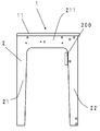
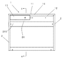
図1、図2において、符号1は机を示し、机1は天板本体部10と、天板本体部10の左右端部側に連結ネジにて連結された左右脚体2、2より構成されている。
符号20は左右脚体2、2を連結する脚体補強材を示し、符号200は、取り付け部材を介して、天板本体部10の後端に連接される拡張天板であって、天板を拡張しない場合には脚体補強材20の前面にネジ止め固定されている。
図5、図6において、符号3は、机1と連結可能な書棚を示している。
The first embodiment will be described in detail with reference to the accompanying drawings.
1 and 2,
5 and 6,
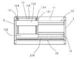
天板本体部10は、図3に示すように、主に左右方向に長い長方形板状の天板11と、天板11下面に左右方向に延伸する前後一対のガイドレール12、12に左右移動可能に吊り下げられる引き出しユニット13で構成されている。
As shown in FIG. 3, the top plate
ガイドレール12は、前後一対で同形状のものが対称に配設されているので前側のガイドレール12のみを詳述する。
ガイドレール12は、図2、図4に示すように、図正面視において、左右脚体2、2間の長さに形成され、側面視で、天板11の下面から下方に延出したレール基部12a、レール基部12aから前方に延出した受け部12bで形成され、レール基部12aは前面が垂直で、後面が上面から前側下方に向かって傾斜面12cを形成し、下面が水平となる形態であって、レール基部12aの前面下部より方形の受け部12bが形成されている。
Since the guide rails 12 of the same shape are symmetrically disposed in a pair of front and rear, only the
As shown in FIGS. 2 and 4, the
引き出しユニット13は、図3、図4に示すように、天板11の下面で、天板11の先端から、脚体補強材20の前面間のほぼ全幅にわたって形成され、所定の間隔で配設された引出左右側板131、131と、引出左右側板131、131下面に、引出左右側板131、131間の左右方向にわたって、前後一対に配設される引出側板補強桟132、132と、引出左右側板131、131上面のそれぞれに、前後一対に取り付けられるスライド部材133、133、133、133と、引出左右側板131、131の対向する面に取り付けられる引き出し支持用部材134、134(レール部材等)を介して前後方向で出入自在とされる引き出し135で構成されている。
As shown in FIGS. 3 and 4, the
スライド部材133は、前後一対で同形状のものが対称に配設されているので前側のスライド部材133のみを詳述する。
スライド部材133は、正面視において、引出左右側板131の巾寸法と略同じ巾に形成され、図4に示すように、側面視で、引出左右側板131の上面から上方に立ち上がる長方形の基部133aと、基部133aの上部後面から後方に向かって延出する係り部133bと、基部133aの上面と係り部133bの上面を繋ぐように上方に円弧状に膨出した滑動部133cで形成されている。すなわち、上下逆向きのL字状に形成されている。
Since the
The
このように構成された天板本体部10の側面より、引き出しユニット13を、ガイドレール12の受け部12bの上面に、スライド部材133の係り部133bの下面が載置するように、引き出しユニット13を左右方向に移動させながらスライド部材133とガイドレール12を係合させる。あるいは、天板本体部10に引き出しユニット13を所定の位置に配置したのち、あらかじめ取り外しておいたガイドレール12を、ガイドレール12の受け部12bの上面に、スライド部材133の係り部133bの下面が載置するように、天板11下面にネジ止めし、スライド部材133とガイドレール12を係合させる。
The
このように天板本体部10に係合した引き出しユニット13は、ガイドレール12の長さの範囲で左右方向にスライド移動が可能となる。
尚、スライド部材133の滑動部133cは、引き出しユニット13が上方に移動することによって発生するガタツキを抑えるため、膨出形態の上端部を天板11の下面に接触させている。また、滑動部133cは、膨出形態の上端部を天板11の下面に接触させているので、天板11とは略線接触となり、過度な抵抗が生まれず、引き出しユニット13の左右移動時に過度に重くなることや、引っかかりが生まれ左右移動がし難いといった問題を解消できる。
Thus, the
In addition, the sliding part 133c of the
左右脚体2、2は対向した対称形に形成されているので、一方側のみ説明する。
右側脚体2は、前後に離間して配置する角柱状の前支持脚21、後支持脚22と、前支持脚21、後支持脚22の上部で、前支持脚21と後支持脚22を連結する上部補強材221が一体的に形成され、側面視で下向きコ字状に構成されている。
そして、左右脚体2、2は、天板11の下面とネジ止め固定される。
Since the left and
The
The left and
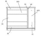
書棚3は、図7、図9に示すように、大収納部300と小収納部400で構成され、該書棚3の上面が、机の天板11の上面と同じ高さとなるように設定され、小収納部400は、垂直軸を中心に回転できるように形成されている。
大収納部300は、平面視において、机の天板11と略同じ横幅で、奥行きは、机の天板11の奥行き寸法の約半分程度に設定された横長長方形のベース体31と、ベース体31の小収納部300側と対向側の側端部の上面に立設する側板32と、該側端部の対向端部より小収納部300が収まる寸法分内側寄りの上面に立設する中側板33と、側板32、中側板33の上端面に載置、着脱自在に連結される平面視においてベース体31と略同形に形成される板状の書棚天板30と、側板32、33間に着脱自在に架設される上下背板35、35、中間背板36、同じく側板32、33間に着脱自在に架設される大棚板38で構成されている。
そして、大収納部300は平面視で横長長方形になるように形成され、長辺の一面側、すなわち、背板の対向面側が開放された開口部300aとされ、収納部の物品の出し入れ口とされる。
As shown in FIGS. 7 and 9, the
The
The
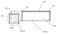
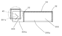
このように構成される大収納部300には、図10に示すように、中側板33から、側方に向かってベース体31と書棚天板30が突き出しており、ベース体31と書棚天板30と中側板33で一側面と前後面が開放された空間301が形成される。
As shown in FIG. 10, in the
空間301は、平面視で略正方形に形成されており、空間301に位置する書棚天板突部30aと、同じく空間301に位置するベース体突部31aも平面視で略正方形を形成している。
そして、空間301に位置する書棚天板突部30aの下面とベース体突部31aの上面にガイド溝301aが設けられている。
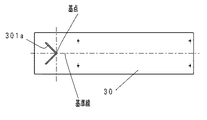
書棚天板突部30aのガイド溝301aは、図12で示すように棚天板突部30aの中心を基点とし、書棚3の長尺方向と平行な線を基準線として、基準線から斜め後方で空間301の開放された側面側に向かって延伸している。
そして、同じく平面視で略正方形の書棚天板突部30aの中心を基点とし、書棚3の長尺方向と平行な線を基準線として、基準線から斜め前方で空間301の開放された側面側に向かって延伸している。したがって、ガイド溝301aは基点を同じとした、前方側のガイド溝と後方側のガイド溝によってV字状に形成されている。
ガイド溝の幅と深さは、後述する書棚3に設けられた回転軸45が入る程度に設定されている。
尚、実施例におけるガイド溝301aは、基準線から45度の角度で、それぞれ斜め前方と後方で空間301の開放された側面に向かって延伸しており、2本のガイド溝の間の角度は90度で設定される。図13で示すようにベース体突部31aの上面のガイド溝301aも、書棚天板突部30aのガイド溝301aと対向して同じ形態なものである。
The
And the guide groove 301a is provided in the lower surface of the bookshelf top-plate protrusion 30a located in the
As shown in FIG. 12, the guide groove 301a of the bookshelf top plate protrusion 30a is obliquely rearward from the reference line, with the center of the shelf top plate protrusion 30a as the base point and a line parallel to the longitudinal direction of the
Similarly, the side of the open side of the
The width and depth of the guide groove are set such that a
The guide groove 301a in the embodiment extends at an angle of 45 degrees from the reference line and extends obliquely forward and rearward toward the open side surface of the
小収納部400は、図11に示すように左右対称の一対に立設する小側板40、40と、小側板40の後端部の小側板40、40間に架設される背面板41と、小側板40の下端部の小側板40、40間に水平に架設される小底板42と、小側板40の上端部の小側板40、40間に水平に架設される小天板43と、同じく小側板40、40間の中間高さで着脱自在に架設される棚板44で構成されている。
そして、小天板43には、小天板43の中心部から上方に向かって回転軸45が立設しており、小天板43の上面の回転軸45の周囲に滑り板46が貼り付けられている。
また、小底板42の下面にも、小底板42の中心部から下方に向かって回転軸45が立設しており、小底板42の下面の回転軸45の周囲に滑り板46が貼り付けられている。そして、小収納部400は平面視で略正方形になるように形成され、四辺の一面側、すなわち、背面板41の対向面側が開放された開口部400aとされ収納部の出し入れ口とされる。
As shown in FIG. 11, the
The small
A rotating
このように形成された大収納部300と小収納部400を組み合わせて書棚3は形成されるので、大収納部300と小収納部400を組み合わせ方法について詳述する。
大収納部300の書棚天板30は、公知技術である(例えば特許第5336129号に記載されているノックダウン金具5)連結金具50(後述する)よって、側板32、中側板33の上面に取り付けられているから、連結金具50の締結を解き、書棚天板30を取り外す。
Since the
The
次に、ベース体突部31aの上面のガイド溝301aに、小収納部400の小底板42側の回転軸45を差込み、小収納部400を垂直に立てた後、書棚天板30を、書棚天板突部30aのガイド溝301aに小収納部400の小天板43の回転軸45を差込みながら、側板32、中側板33の上面に取り付ける。
そして、小収納部400の開放面側を正面に向け、ガイド溝301aに沿って、小収納部400をスライド移動させ、小側板40の側面と中側板33の側面が沿う状態とする(図7の状態)。
小側板40と中側板33をネジにて固定し、書棚3の組み立ては完了する。
尚、中側板33の外面側には、あらかじめ螺合孔が設けられ、小側板40には該螺合孔に対応した貫通穴が設けられている。ネジは、小収納部400の内面側より該貫通穴を貫通して中側板33の螺合孔に取り付けられる。
Next, the
Then, the
The
Note that a screwing hole is provided in advance on the outer surface side of the
小収納部400を回転させる方法は、まず前述のネジを取り外し、小収納部400を、ガイド溝301aに沿って斜め前方外側にスライド移動させる。この状態で小収納部400の回転軸45が、ガイド溝301aに沿って斜め前方外側に移動しているので、小収納部400の回転の中心が前方外側に移動していることとなる。
そして、この状態で、小収納部400を90度回転させ、開口部400aが外側を向いた状態で、ガイド溝301aに沿って、小収納部400をスライド移動させ、小側板40の背面板41と中側板33の側面が沿う状態とする。前述の中側板33の外面側の螺合孔に合わせて、あらかじめ貫通穴が設けられた背面板41の貫通穴を利用し、背面板41と中側板33をネジにて固定し、小収納部400の回転作業は完了する。
同じ作業要領で、小収納部400をさらに90度回転させると、小収納部400の開口部400aを書棚3の背面側に向けることができる。
As a method of rotating the
Then, in this state, the
When the
小収納部400は、平面視で略正方形を成すから、小収納部400の回転時には、平面視で、略正方形の対角線を直径とした回転軌跡を描くこととなる(図14、15に一点鎖線で示す)。
したがって、ガイド溝301aに沿って回転中心軸を外側前方に移動させることにより、小収納部400の回転時の回転軌跡が、大収納部300の中側板33と干渉しない(図14)。そのため、小収納部400は、小収納部400が内包する大収納部300の空間301に対して、略同じ容量とすることが可能となり、大きな収納量を確保できる。
また、回転中心軸を外側前方に移動させることにより、書棚3の背面に壁があったとしても、小収納部400の回転時の回転軌跡が壁と干渉しないので、書棚3を移動させることなく、小収納部400の開放側の向きを変えることが容易にできる。
Since the
Therefore, by moving the rotation center axis forward and outward along the guide groove 301a, the rotation trajectory during rotation of the
Moreover, even if there is a wall on the back of the
そして、大収納部300のガイド溝301aには後方側のガイド溝が設けられているから、小収納部400は、外側後方に移動させて(図15)から回転させることもできる。この後方側のガイド溝によって、書棚3全体を垂直軸中心に180度回転させて、大収納部300と小収納部400の左右の並びを変えることができる。180度回転させて、大収納部300と小収納部400の左右の並びを変えた場合、前記の後方側のガイド溝は、必然的に前方側のガイド溝に変化するので、前述のとおり小収納部400を回転させることができる。
And since the guide groove 301a of the large
ただし、この場合、大収納部300の上下背板35、35、中間背板36は、背面側から前面側となるから、上下背板35、35、中間背板36を一旦外し、前面側から背面側に移設する。そのため、上下背板35、35、中間背板36は、書棚天板30と同じく公知技術である連結金具50で着脱自在に連結されている。
However, in this case, since the upper and
このように、ガイド溝301aは、前方側のガイド溝と後方側のガイド溝の両方備えており、かつ、基点も同じであるから、小収納部400は前方側でも後方側でもスライド移動可能となり、大収納部400の背板も前面側と背面側で移設可能であるから、書棚3を右用、左用で兼用できるので、部屋のレイアウトに合わせることができるので使い勝手が良い。また、ガイド溝301aは基点を同じとした、前方側のガイド溝と後方側のガイド溝によってV字状に限定されるものではなく、例えば基点から側方に横移動する溝を設け、該溝端を基点として前方側のガイド溝と後方側のガイド溝をV字状に設けた形状のY字状にする方法でもよく、したがって、小収納部400の回転軸が、斜め前方側と斜め後方側に移動できる形状であればよい。
As described above, the guide groove 301a includes both the front side guide groove and the rear side guide groove, and the base point is the same. Therefore, the
そして、小収納部400の下面には、フッ素樹脂製などの滑りが良い滑り板46が貼り付けられているので、小収納部400に物品を入れて重量が増した状態あっても、小収納部400のスライド移動や回転が行える。
また、小収納部400の上面にも同じく滑り板46が貼り付けられているので、書棚天板30上に荷重がかかった状態であっても小収納部400のスライド移動や回転が行える。
滑り板46は、フッ素樹脂製などの滑りの良い材質のものを貼り付けるだけであるから安価である。
尚、大収納部300の中側板33は、小収納部の近傍に設置した方が、書棚天板突部30aの左右方向の長さが短くなるので、書棚天板突部30aが撓みにくくなるので、小収納部400のスライド移動や回転が行いやすくなり都合がよい。
Since the sliding
Further, since the sliding
The sliding
In addition, since the length in the left-right direction of the bookshelf top plate protrusion 30a is shorter when the
連結金具50について、図16に基づき詳述する。
連結金具50は、連結ピン502と、円柱状の締結金具501とからなるもので、連結ピン502の一端部が雄ねじ部503とされ、他端部には小径軸部504、小径軸部504の先端には大径頭部505が一体的に形成されている。締結金具501は、前記大径頭部505が係合する係合溝孔506と、小径軸部504が摺動可能に嵌合される溝幅の小さな円弧状のガイド溝507とが、互いに連通するようにして円周方向に向かって形成され、平面部には、ドライバーなどで締結金具501を回転させる回転溝508が形成されている。
このような連結金具は公知技術であるのは前述のとおりである。
The connecting metal fitting 50 will be described in detail with reference to FIG.
The connection fitting 50 is composed of a
As described above, such a connecting metal fitting is a known technique.
例えば、書棚天板30と中側板33を連結するには、書棚天板30の下面に設けられた螺孔60に、連結ピン502の雄ねじ部503を螺合させて取り付ける。
そして、該連結ピン502の大径頭部505側を中側板33の上面の連結孔331に差込む。このとき、連結ピン502の小径軸部504と大径頭部505を、連結金具50のガイド溝507と係合溝孔506とに嵌合する。
そして、連結金具50を、回転溝508を使い工具などで回動させると連結ピン502と連結金具50とが互いに係合して、書棚天板30と中側板33とが不動に連結される。
当然ながら、連結金具50を、反対方向に回動させると連結ピン502は係合状態を解除され、書棚天板30と中側板33は分割される。
For example, in order to connect the
Then, the large-
When the connection fitting 50 is rotated with a tool or the like using the
Naturally, when the connecting
本発明は上記の如く構成され、机1と書棚3は、机1の天板11の下面と書棚3の書棚天板30の下面間に金属製平板の連結金物を掛け渡し、金物を天板11の下面と書棚天板30の下面それぞれでネジ止め固定し、机1と書棚3を連結して使用することができる。
The present invention is configured as described above, and the
本発明品での机1と書棚3の組み合わせ方法は、図18〜図22に示すように多彩な配置が可能である。図18〜図22における矢印は、小収納部400の開口部400a、大収納部の開口部300aの向きを示しており、図18は、机1の後方に書棚3を配置した体系を示しており、基本的に机1と書棚3は連結金物で連結されている。図19は、机1の右側方に書棚3を配置した体系を示しており、開口部300aが内側を向く体系である。図20は、同じく机1の右側方に書棚3を配置した体系を示しており、開口部300aが外側を向く体系である。
机1の左側方に書棚3を配置した体系は、図19、図20の体系の対称形となり、図21、図22に示すようになる。
The combination method of the
The system in which the
机1の側方部に書棚3を配置する場合に、通常は、机1の脚体2を取り外さずに書棚3を配置するが、書棚側の机の脚体2を外して、机1にかかる荷重を書棚3で受けることによって、書棚3の収納部の正面側の障害物を省き、書棚の使い勝手を向上させることができる。取り外した脚体2は、脚体補強材20の背面に、脚体補強材20と重ねた状態でネジ止め固定される。
When the
机1の一側方部に書棚3を配置し、前述の左右方向に移動可能にされた引き出しユニット13を他側方部側にスライド移動させると、書棚3の収納部の物品の出し入れ時に引き出しユニット13が邪魔にならず、書棚3の収納部がより見えやすくなるので、書棚3の収納部の使い勝手がさらに向上する。
When the
このように、収納部の開口部の向きを変更することにより一種類の書棚で様々な机との組み合わせが可能なので、組み合わせデスクを配置する部屋のレイアウトに合わせて使い勝手のよい組み合わせを提供できる。 Thus, by changing the direction of the opening of the storage unit, it is possible to combine a variety of desks with a single type of bookcase. Therefore, it is possible to provide a user-friendly combination in accordance with the layout of the room where the combination desk is placed.
図17は、机1の天板11の後単に拡張天板200を連結したものと書棚3を組み合わせたものであり、本発明の机と書棚は、拡張天板の有無に関係なく組み合わせを行うことができる。さらに書棚3の上部に上部書棚3aを連結載置し、書棚を2段重ねに配置しても、本発明の机と書棚は、前述のように組み合わせを行うことができる。
尚、小収納部、大収納部の開口部は収納部の出し入れ口であるから、開口部には開閉自在の扉を設けてもよい。
FIG. 17 is a combination of the
In addition, since the opening part of a small accommodating part and a large accommodating part is an entrance / exit of an accommodating part, you may provide a door which can be opened and closed in an opening part.
以上のように、本発明は、書棚に大収納部と小収納部を設け、それぞれの収納部の開口方向を変更できるので、机と書棚の組合せパターンを多彩にすることができ、組み合わせデスクを設置する部屋のレイアウトに合わせて、使い勝手のよい机と書棚の組み合わせが可能であるから、家庭等の勉強部屋や書斎等の執務空間で広く利用することができる。 As described above, the present invention provides a large storage section and a small storage section on the bookshelf and can change the opening direction of each storage section. It can be used in a study room at home or office space such as a study room because it can be combined with a convenient desk and bookcase according to the layout of the room.
1 机
10 天板本体部
11 天板
13 引き出しユニット
2 左右脚体
3 書棚
30 書棚天板
31 ベース体
32 側板
33 中側板
300 大収納部
301 空間
301a ガイド溝
400 小収納部
45 回転軸
1
3
Claims (3)
Priority Applications (1)
| Application Number | Priority Date | Filing Date | Title |
|---|---|---|---|
| JP2017088118A JP6813888B2 (en) | 2017-04-27 | 2017-04-27 | Combination desk |
Applications Claiming Priority (1)
| Application Number | Priority Date | Filing Date | Title |
|---|---|---|---|
| JP2017088118A JP6813888B2 (en) | 2017-04-27 | 2017-04-27 | Combination desk |
Publications (2)
| Publication Number | Publication Date |
|---|---|
| JP2018183488A true JP2018183488A (en) | 2018-11-22 |
| JP6813888B2 JP6813888B2 (en) | 2021-01-13 |
Family
ID=64356592
Family Applications (1)
| Application Number | Title | Priority Date | Filing Date |
|---|---|---|---|
| JP2017088118A Active JP6813888B2 (en) | 2017-04-27 | 2017-04-27 | Combination desk |
Country Status (1)
| Country | Link |
|---|---|
| JP (1) | JP6813888B2 (en) |
-
2017
- 2017-04-27 JP JP2017088118A patent/JP6813888B2/en active Active
Also Published As
| Publication number | Publication date |
|---|---|
| JP6813888B2 (en) | 2021-01-13 |
Similar Documents
| Publication | Publication Date | Title |
|---|---|---|
| JP2012217852A (en) | Furniture with at least one sliding door | |
| JP2018183489A (en) | Combination desk | |
| JP2018183488A (en) | Combination desk | |
| JPH0635051Y2 (en) | Goods storage | |
| JP2015223189A (en) | drawer | |
| JP2018000588A (en) | Combination desk | |
| JP4943252B2 (en) | Desk equipment | |
| TWM520315U (en) | Cabinet structure for accommodating makeup mirror | |
| CA3056566A1 (en) | Multi-use desk-cabinet | |
| JP2007000650A (en) | Storage furniture such as kitchen cabinet having hanging tool | |
| KR200251920Y1 (en) | Multipurpose cabinet | |
| JP3233114U (en) | Folding desk | |
| JP6634220B2 (en) | Storage furniture | |
| JP2016214689A (en) | Storage device | |
| JP2001321229A (en) | Computer desk | |
| JP5637831B2 (en) | Desk system | |
| KR200411326Y1 (en) | desk furniture united with movable desk | |
| US20200187640A1 (en) | Workstation | |
| EP3241461A1 (en) | Furnishing element | |
| JP2021016635A (en) | Combination desk | |
| KR20160002101U (en) | Multi-fetched expressions cabinet | |
| JP4285208B2 (en) | Storage furniture | |
| JP3994032B2 (en) | Bookend | |
| KR200376709Y1 (en) | A desc drawer eqipped with board for a key board and a mouse | |
| KR20130038667A (en) | Storage furniture having a sliding type table |
Legal Events
| Date | Code | Title | Description |
|---|---|---|---|
| A621 | Written request for application examination |
Free format text: JAPANESE INTERMEDIATE CODE: A621 Effective date: 20200227 |
|
| A977 | Report on retrieval |
Free format text: JAPANESE INTERMEDIATE CODE: A971007 Effective date: 20201125 |
|
| TRDD | Decision of grant or rejection written | ||
| A01 | Written decision to grant a patent or to grant a registration (utility model) |
Free format text: JAPANESE INTERMEDIATE CODE: A01 Effective date: 20201208 |
|
| A61 | First payment of annual fees (during grant procedure) |
Free format text: JAPANESE INTERMEDIATE CODE: A61 Effective date: 20201211 |
|
| R150 | Certificate of patent or registration of utility model |
Ref document number: 6813888 Country of ref document: JP Free format text: JAPANESE INTERMEDIATE CODE: R150 |
|
| R250 | Receipt of annual fees |
Free format text: JAPANESE INTERMEDIATE CODE: R250 |