JP6684923B2 - Electric coupling for programmable motion automation - Google Patents
Electric coupling for programmable motion automation Download PDFInfo
- Publication number
- JP6684923B2 JP6684923B2 JP2018556270A JP2018556270A JP6684923B2 JP 6684923 B2 JP6684923 B2 JP 6684923B2 JP 2018556270 A JP2018556270 A JP 2018556270A JP 2018556270 A JP2018556270 A JP 2018556270A JP 6684923 B2 JP6684923 B2 JP 6684923B2
- Authority
- JP
- Japan
- Prior art keywords
- electric coupling
- drive motor
- fixing device
- supports
- energy
- Prior art date
- Legal status (The legal status is an assumption and is not a legal conclusion. Google has not performed a legal analysis and makes no representation as to the accuracy of the status listed.)
- Active
Links
- 238000010168 coupling process Methods 0.000 title claims description 106
- 238000005859 coupling reaction Methods 0.000 title claims description 106
- 230000008878 coupling Effects 0.000 title claims description 102
- 230000033001 locomotion Effects 0.000 title claims description 30
- 238000000034 method Methods 0.000 claims description 12
- 230000008569 process Effects 0.000 claims description 12
- 230000005540 biological transmission Effects 0.000 claims description 8
- 239000000470 constituent Substances 0.000 claims description 4
- 230000000694 effects Effects 0.000 claims description 3
- 230000008901 benefit Effects 0.000 description 11
- 238000004146 energy storage Methods 0.000 description 5
- 238000010276 construction Methods 0.000 description 4
- 230000008439 repair process Effects 0.000 description 3
- 238000005096 rolling process Methods 0.000 description 3
- 230000009471 action Effects 0.000 description 2
- 238000005516 engineering process Methods 0.000 description 2
- 238000004519 manufacturing process Methods 0.000 description 2
- NJPPVKZQTLUDBO-UHFFFAOYSA-N novaluron Chemical compound C1=C(Cl)C(OC(F)(F)C(OC(F)(F)F)F)=CC=C1NC(=O)NC(=O)C1=C(F)C=CC=C1F NJPPVKZQTLUDBO-UHFFFAOYSA-N 0.000 description 2
- 238000003860 storage Methods 0.000 description 2
- 239000003990 capacitor Substances 0.000 description 1
- 230000001419 dependent effect Effects 0.000 description 1
- 239000002184 metal Substances 0.000 description 1
Images


Classifications
-
- B—PERFORMING OPERATIONS; TRANSPORTING
- B25—HAND TOOLS; PORTABLE POWER-DRIVEN TOOLS; MANIPULATORS
- B25J—MANIPULATORS; CHAMBERS PROVIDED WITH MANIPULATION DEVICES
- B25J17/00—Joints
- B25J17/02—Wrist joints
- B25J17/0241—One-dimensional joints
-
- B—PERFORMING OPERATIONS; TRANSPORTING
- B25—HAND TOOLS; PORTABLE POWER-DRIVEN TOOLS; MANIPULATORS
- B25J—MANIPULATORS; CHAMBERS PROVIDED WITH MANIPULATION DEVICES
- B25J9/00—Programme-controlled manipulators
- B25J9/0009—Constructional details, e.g. manipulator supports, bases
-
- B—PERFORMING OPERATIONS; TRANSPORTING
- B25—HAND TOOLS; PORTABLE POWER-DRIVEN TOOLS; MANIPULATORS
- B25J—MANIPULATORS; CHAMBERS PROVIDED WITH MANIPULATION DEVICES
- B25J9/00—Programme-controlled manipulators
- B25J9/08—Programme-controlled manipulators characterised by modular constructions
-
- B—PERFORMING OPERATIONS; TRANSPORTING
- B25—HAND TOOLS; PORTABLE POWER-DRIVEN TOOLS; MANIPULATORS
- B25J—MANIPULATORS; CHAMBERS PROVIDED WITH MANIPULATION DEVICES
- B25J9/00—Programme-controlled manipulators
- B25J9/10—Programme-controlled manipulators characterised by positioning means for manipulator elements
- B25J9/102—Gears specially adapted therefor, e.g. reduction gears
-
- B—PERFORMING OPERATIONS; TRANSPORTING
- B25—HAND TOOLS; PORTABLE POWER-DRIVEN TOOLS; MANIPULATORS
- B25J—MANIPULATORS; CHAMBERS PROVIDED WITH MANIPULATION DEVICES
- B25J9/00—Programme-controlled manipulators
- B25J9/10—Programme-controlled manipulators characterised by positioning means for manipulator elements
- B25J9/12—Programme-controlled manipulators characterised by positioning means for manipulator elements electric
- B25J9/126—Rotary actuators
-
- B—PERFORMING OPERATIONS; TRANSPORTING
- B25—HAND TOOLS; PORTABLE POWER-DRIVEN TOOLS; MANIPULATORS
- B25J—MANIPULATORS; CHAMBERS PROVIDED WITH MANIPULATION DEVICES
- B25J19/00—Accessories fitted to manipulators, e.g. for monitoring, for viewing; Safety devices combined with or specially adapted for use in connection with manipulators
- B25J19/0004—Braking devices
-
- B—PERFORMING OPERATIONS; TRANSPORTING
- B25—HAND TOOLS; PORTABLE POWER-DRIVEN TOOLS; MANIPULATORS
- B25J—MANIPULATORS; CHAMBERS PROVIDED WITH MANIPULATION DEVICES
- B25J9/00—Programme-controlled manipulators
- B25J9/10—Programme-controlled manipulators characterised by positioning means for manipulator elements
- B25J9/102—Gears specially adapted therefor, e.g. reduction gears
- B25J9/1025—Harmonic drives
Landscapes
- Engineering & Computer Science (AREA)
- Robotics (AREA)
- Mechanical Engineering (AREA)
- Manipulator (AREA)
- Retarders (AREA)
- Braking Arrangements (AREA)
Description
本発明は、互いに相対運動可能な2つのハウジング部材と、駆動モータと、該駆動モータに対して伝動技術的に後置された歯車装置とを有し、プログラミング可能な運動自動装置の互いに相対運動可動な2つの支持体を連結するための電動継手(電動ジョイント)に関する。 The present invention has two housing members which are movable relative to each other, a drive motor and a gearing which is mechanically arranged behind the drive motor, the relative movement of a programmable motion automatic device being relative to one another. The present invention relates to an electric joint (electric joint) for connecting two movable supports.
下記特許文献1から、プログラミング可能なロボットシステムが既知である。該ロボットシステムは、所定数の個々のアーム部分を備えたロボットを含み、この際、隣接するアーム部分は、それぞれ1つの継手(ジョイント)により互いに連結されている。更に該ロボットシステムは、少なくとも1つの継手内に、制御可能な駆動部と、該駆動部を制御するための制御システムを含んでいる。更に該ロボットシステムは、該ロボットシステムをプログラミングすることのできる利用者インタフェースを有する。前記継手は、ハウジングと、該ハウジング内に配設されたモータを有し、該モータは、ハウジングに対して相対回転するモータ軸を有する。ハウジング内には、更に安全ブレーキが設けられている。該ロボットシステムの継手は、一方の継手部分が極めて大きな容積を必要として太く構成されているのに対し、それぞれ他方の継手部分は極めて小さく構成されていることにより完全に非対称に構成されている。 A programmable robot system is known from DE 10 2004 009 421 A1. The robot system comprises a robot with a certain number of individual arm parts, wherein adjacent arm parts are each connected to one another by a joint. Further, the robot system includes a controllable drive in at least one joint and a control system for controlling the drive. Furthermore, the robot system has a user interface with which the robot system can be programmed. The joint has a housing and a motor disposed in the housing, and the motor has a motor shaft that rotates relative to the housing. A safety brake is also provided in the housing. The joints of the robot system are made completely asymmetric by virtue of the fact that one joint part is made thicker, requiring a very large volume, whereas the other joint part is made very small.
本発明の課題は、冒頭に記載した形式の電動継手を、特に作用する力及び/又はモーメントの支持に関して有利に構成することのできる可能性を提供することである。 The object of the present invention is to provide the possibility that an electric coupling of the type mentioned at the outset can be constructed in an advantageous manner, in particular with regard to the support of the forces and / or moments acting on it.
前記課題は、歯車装置の一部分がハウジング部材のうち一方のハウジング部材内に配設され、歯車装置の他の部分が他方のハウジング部材内に配設されていることにより特徴付けられた電動継手により解決される。
即ち本発明の第1の視点により、互いに相対運動可能な2つのハウジング部材と、駆動モータと、該駆動モータに対して伝動技術的に後置された歯車装置とを有し、プログラミング可能な運動自動装置の互いに相対運動可動な2つの支持体を連結するための電動継手であって、歯車装置の一部分がハウジング部材のうち一方のハウジング部材内に配設され、歯車装置の他の部分が他方のハウジング部材内に配設されていることを特徴とする電動継手が提供される。
より詳しくは、前記第1の視点において、互いに相対運動可能な2つのハウジング部材と、駆動モータと、該駆動モータに対して伝動技術的に後置された歯車装置とを有し、プログラミング可能な運動自動装置の互いに相対運動可動な2つの支持体を連結するための電動継手であって、歯車装置の一部分がハウジング部材のうち一方のハウジング部材内に配設され、歯車装置の他の残りの部分が他方のハウジング部材内に配設されていることを特徴とする。
更に本発明の第2の視点により、前記電動継手を用いて互いに相対運動可能に連結される2つの支持体を備えたプログラミング可能な運動自動装置が提供される。
尚、本願の特許請求の範囲において場合により付記される図面参照符号は、専ら本発明の理解の容易化のためのものであり、図示の形態への限定を意図するものではないことを付言する。
According to the electric coupling, a part of the gear device is arranged in one of the housing members and the other part of the gear device is arranged in the other housing member. Will be resolved.
That is to say, according to a first aspect of the invention, a programmable movement comprising two housing members which are movable relative to one another, a drive motor and a gearing which is mechanically arranged after the drive motor. An electric coupling for connecting two supports that are movable relative to each other in an automatic device, wherein a part of the gear device is arranged in one of the housing members and the other part of the gear device is arranged in the other An electric coupling is provided which is disposed in the housing member of the.
More specifically, in the first aspect, the housing has two housing members that can move relative to each other, a drive motor, and a gear device that is technically arranged behind the drive motor, and is programmable. An electric coupling for connecting two supports which are movable relative to each other of a motion automatic device, wherein a part of the gear device is arranged in one of the housing members, and the other part of the gear device is The part is arranged in the other housing member.
Further according to a second aspect of the invention, there is provided a programmable motion automatic device comprising two supports movably connected to each other by means of said electric coupling.
It is to be noted that reference numerals in the drawings, which are sometimes added in the claims of the present application, are solely for facilitating the understanding of the present invention, and are not intended to be limited to the illustrated forms. .
本発明において、以下の形態が可能である。In the present invention, the following modes are possible.
(形態1)互いに相対運動可能な2つのハウジング部材と、駆動モータと、該駆動モータに対して伝動技術的に後置された歯車装置とを有し、プログラミング可能な運動自動装置の互いに相対運動可動な2つの支持体を連結するための電動継手であって、歯車装置の一部分がハウジング部材のうち一方のハウジング部材内に配設され、歯車装置の他の部分が他方のハウジング部材内に配設されていること。(Mode 1) Relative movement of a programmable motion automatic device having two housing members that can move relative to each other, a drive motor, and a gear device that is arranged behind the drive motor in transmission technology An electric coupling for connecting two movable supports, wherein a part of the gear device is arranged in one of the housing members and the other part of the gear device is arranged in the other housing member. Be installed.
(形態2)該電動継手において、該電動継手をロックするように構成されて配設された固定装置が設けられていることが好ましい。(Mode 2) In the electric coupling, it is preferable that a fixing device configured and arranged to lock the electric coupling is provided.
(形態3)該電動継手において、(Mode 3) In the electric coupling,
a.固定装置は、直接的に歯車装置構成部材を制動するように構成されて配設されていること、又は、a. The fixing device is arranged and arranged to directly brake the gear device component, or
b.固定装置は、直接的に歯車装置構成部材を制動するように構成されて配設されており、更に固定装置は、歯車装置と同じハウジング部材内か、又は少なくとも歯車装置の直接的に制動すべき構成部材と同じハウジング部材内に配設されていることが好ましい。b. The fixing device is constructed and arranged to brake the gearing component directly, and further the fixing device should be in the same housing member as the gearing or at least directly on the gearing. It is preferably located in the same housing member as the component.
(形態4)該電動継手において、(Mode 4) In the electric coupling,
a.固定装置は、直接的に駆動モータか又は駆動モータの従動軸を制動するように構成されて配設されていること、又は、a. The fixing device is arranged and arranged to brake the drive motor or the driven shaft of the drive motor directly, or
b.固定装置は、直接的に駆動モータか又は駆動モータの従動軸を制動するように構成されて配設されており、更に固定装置は、駆動モータと同じハウジング部材内か、又は駆動モータの従動軸と同じハウジング部材内に配設されていることが好ましい。b. The fixing device is arranged and arranged to brake the drive motor or the driven shaft of the drive motor directly, and the fixing device is arranged in the same housing member as the drive motor or the driven shaft of the drive motor. It is preferably arranged in the same housing member as.
(形態5)該電動継手において、歯車装置は、波動歯車装置であることが好ましい。(Mode 5) In the electric coupling, the gear device is preferably a wave gear device.
(形態6)該電動継手において、固定装置を用いて制動可能でロック可能な歯車装置構成部材は、波動歯車装置のウェーブジェネレータであること、又は、固定装置を用いて制動可能でロック可能な歯車装置構成部材は、波動歯車装置のフレクスプラインであること、又は、固定装置を用いて制動可能でロック可能な歯車装置構成部材は、波動歯車装置のサーキュラスプライン又はダイナミックスプラインであることが好ましい。(Mode 6) In the electric coupling, the gear device component that can be braked and locked using a fixing device is a wave generator of a wave gear device, or a gear device that can be braked and locked using a fixing device. The device component is preferably a flexspline of a wave gear device, or the gear device component that can be braked and locked using a fixing device is preferably a circular spline or a dynamic spline of a wave gear device.
(形態7)該電動継手において、波動歯車装置は、鍋状歯車装置として構成されていること、又は、波動歯車装置は、環状歯車装置として構成されていることが好ましい。(Mode 7) In the electric coupling, it is preferable that the wave gear device is configured as a pan gear device, or the wave gear device is configured as an annular gear device.
(形態8)該電動継手において、固定装置は、作動状態において、予め設定された又は予め設定可能な値を超える値で従動側のトルクが発生する場合には、波動歯車装置の従動要素の構成部材の損傷、及び動力伝達経路内に位置する該電動継手の他の構成部材の損傷を回避するために、該固定装置を用いて直接的にロックされた構成部材の運動を許容することが好ましい。(Mode 8) In the electric coupling, in the operating state, when the driven-side torque is generated at a value exceeding a preset value or a presettable value in the operating state, the structure of the driven element of the wave gear device is configured. In order to avoid damage to the components and other components of the electric coupling located in the power transmission path, it is preferable to allow the movement of the directly locked components with the fixing device. .
(形態9)該電動継手において、前記予め設定された又は予め設定可能な値は、ロックすべき構成部材において発生してよい最大許容の稼働トルクに対応すること、及び/又は、前記予め設定された値は、該電動継手の損傷、及び/又は歯車装置の損傷が排除されているように選択されていることが好ましい。(Mode 9) In the electric coupling, the preset or presettable value corresponds to a maximum allowable operating torque that may occur in a component to be locked, and / or the preset value. Is preferably selected such that damage to the electric coupling and / or damage to the gearing is eliminated.
(形態10)該電動継手において、固定装置は、摩擦結合式のブレーキとして構成されているか、又は摩擦結合式のブレーキを有することが好ましい。(Mode 10) In the electric coupling, the fixing device is preferably configured as a friction coupling type brake or has a friction coupling type brake.
(形態11)該電動継手において、固定装置は、該固定装置を用いて直接的に制動可能な構成部材と摩擦結合式で結合された係止手段を有し、該係止手段は、少なくとも1つの形状係合手段を有し、該形状係合手段は、該固定装置の作動状態において、形状係合式で、ハウジング又はシャーシに対して相対回転不能な対応形状係合手段と協働することが好ましい。(Mode 11) In the electric coupling, the fixing device has a locking means that is frictionally coupled to a component that can be directly braked by using the fixing device, and the locking means is at least 1 And two shape-engaging means, the shape-engaging means cooperating with a corresponding shape-engaging means that is shape-engaging and is non-rotatable relative to the housing or chassis in the actuated state of the fixation device. preferable.
(形態12)該電動継手において、該電動継手は、固定装置へ接続された又は接続可能な少なくとも1つのエネルギー蓄積器を含んでおり、(Mode 12) In the electric coupling, the electric coupling includes at least one energy storage device connected to or connectable to a fixing device,
a.固定装置は、ロック状態からリリース状態へ、又はリリース状態からロック状態へ、少なくとも一回の切替過程をもたらすために、エネルギー蓄積器内に蓄積されたエネルギーの少なくとも一部分を用いて付勢可能であること、又は、a. The locking device is activatable with at least a portion of the energy stored in the energy store to effect at least one switching process from the locked state to the released state or from the released state to the locked state. Or
b.固定装置は、該固定装置をロック状態又はリリース状態に保持するために、エネルギー蓄積器内に蓄積されたエネルギーの少なくとも一部分を用いて付勢可能であること、又は、b. The securing device can be biased with at least a portion of the energy stored in the energy store to hold the securing device in a locked or released state, or
c.エネルギー蓄積器は、機械エネルギーを蓄積するように構成されていること、又は、c. The energy store is configured to store mechanical energy, or
d.エネルギー蓄積器は、電気エネルギーを蓄積するように構成されていることが好ましい。d. The energy store is preferably configured to store electrical energy.
(形態13)該電動継手において、該電動継手は、エネルギーラインを有し、該エネルギーラインは、外部から供給されるエネルギーを固定装置及び/又は駆動モータの稼働及び/又は制御のために伝送すること、及び、固定装置は、エネルギーラインを介したエネルギー供給が遮断されている場合、エネルギー蓄積器内に蓄積されたエネルギーを使用して切替可能であることが好ましい。(Mode 13) In the electric coupling, the electric coupling has an energy line, and the energy line transmits energy supplied from the outside for operating and / or controlling a fixing device and / or a drive motor. Preferably, the fixing device is switchable using the energy stored in the energy store when the energy supply via the energy line is interrupted.
(形態14)該電動継手において、(Mode 14) In the electric coupling,
a.該電動継手は、2つの支持体を、これらの支持体のうち一方の支持体が運動する面と、他方の支持体が運動する面が互いに常に平行に配設されているように連結するかたちで構成されていること、又は、a. The electric coupling connects two supports such that a surface on which one of the supports moves and a surface on which the other support moves are arranged to be always parallel to each other. Consists of, or
b.該電動継手は、ヒンジ継手として構成されていること、b. The electric coupling is configured as a hinge joint,
c.該電動継手は、2つの支持体を、これらの支持体のうち一方の支持体が運動する面が、他方の支持体に対して常に直角に配設されているように連結するかたちで構成されていることが好ましい。c. The electric coupling is formed by connecting two supports such that a surface on which one of the supports moves is always arranged at a right angle to the other support. Preferably.
(形態15)前記電動継手を用いて互いに相対運動可能に連結されている2つの支持体を備えたプログラミング可能な運動自動装置。(Mode 15) A programmable motion automatic device including two supports which are connected to each other so as to be movable relative to each other using the electric coupling.
(形態16)該運動自動装置において、支持体のうち一方の支持体は、直接的に又は間接的に駆動モータのステータ及び/又は駆動モータの駆動モータハウジングと相対回転不能に結合されていること、及び他方の支持体は、歯車装置の従動要素へ相対回転不能に連結されていることが好ましい。(Mode 16) In the motion automatic device, one of the supports is directly or indirectly coupled to the stator of the drive motor and / or the drive motor housing of the drive motor so as not to rotate relative to each other. , And the other support is preferably non-rotatably connected to the driven element of the gear train.
(形態17)該運動自動装置において、前記電動継手を用いて可動に連結された2つの支持体は、ロボットアームの一部分であることが好ましい。(Mode 17) In the motion automatic device, it is preferable that the two supports that are movably connected to each other by using the electric coupling are part of a robot arm.
(形態18)該運動自動装置において、前記電動継手は、互いに相対運動可能な2つのハウジング部材を有し、(Mode 18) In the automatic movement device, the electric coupling has two housing members that can move relative to each other,
a.支持体のうち一方の支持体は、ハウジング部材のうち一方のハウジング部材と固定結合されており、他方の支持体は、他方のハウジング部材と固定結合されていること、又は、a. One of the supports is fixedly coupled to one of the housing members, and the other support is fixedly coupled to the other housing member, or
b.ハウジング部材のうち一方のハウジング部材は、支持体のうち一方の支持体であること、又は、b. One of the housing members is one of the supports, or
c.ハウジング部材のうち一方のハウジング部材は、支持体のうち一方の支持体のハウジングの構成要素であり、他方のハウジング部材は、他方の支持体のハウジングの構成要素であることが好ましい。c. Preferably, one of the housing members is a component of the housing of one of the supports, and the other housing member is a component of the housing of the other support.
独自の一発明思想により、また特に以下で説明する構成又は従属請求項に記載された構成の1つ又は複数との組み合わせにおいて、選択的には、駆動モータがハウジング部材のうち一方のハウジング部材内に配設され、歯車装置が他方のハウジング部材内に配設されていることをも提案することができる。 In accordance with one of its own inventive ideas, and in particular in combination with one or more of the arrangements described below or in the dependent claims, the drive motor is optionally in one of the housing members. It can also be proposed that the gearing is arranged in the other housing member.
本発明は、ハウジング部材(2つのハウジング部材)が、対称にか及び/又は同じ構造で及び/又は同じ大きさで構成されることが可能であるという優れた利点を有する。特に、継手部材(複数)のうち一方の継手部材が、駆動モータの全要素も、歯車装置と固定装置の全要素も受容しなくてはならないことを理由に当該継手部材が特に太く構成するということは、要求されない。ハウジング部材(複数)が同じ構造である一実施形態は、比較的低コストで製造可能であり、それは、同じ製造工具を用いて両方のハウジング部材を製造することが可能であり、それにより様々な製造工具は不必要なためである。 The invention has the great advantage that the housing members (two housing members) can be constructed symmetrically and / or of the same construction and / or of the same size. In particular, one of the joint members (plurality) is said to be particularly thick because one joint member must receive all elements of the drive motor as well as all elements of the gearing and the fixing device. Things are not required. One embodiment, where the housing members are of the same construction, can be manufactured at a relatively low cost, which allows both housing members to be manufactured using the same manufacturing tool, thereby varying This is because manufacturing tools are unnecessary.
本発明の格別優れた利点は、支持体(2つの支持体)の縦中軸線が運動する面が、互いに比較的僅かな間隔を有することが可能であるということにある。このことは、稼働時に少なくとも支持体のうち一方の支持体に対して作用する捩りモーメントが比較的僅かであるという更なる優れた利点を有する。従って支持体は、より細く及び/又は構成空間を節約するように寸法決定されることが可能である。 A particularly good advantage of the invention is that the planes on which the median axes of the supports (two supports) move can have a relatively small distance from one another. This has the further advantage that, during operation, the torsional moment acting on at least one of the supports is relatively small. Thus, the support can be dimensioned to be narrower and / or save construction space.
特に本発明は、電動継手を駆動部構成部材及び歯車装置構成部材の配置構成に関してよりフレキシブルに且つ特に特定用途で有利に構成することを可能とする。特に例えばヒンジ継手としての一実施形態では、支持体(2つの支持体)の縦中軸線が運動する面の間の中間空間から外に所定の構成部材を移すことが可能とされ、それによりそれらの面は、既述したように、互いに比較的僅かな間隔を有することが可能である。ヒンジ継手(ないし関節 Gelenk)としては、特に専ら所定の自由度での回転運動を可能とする継手として理解される。 In particular, the present invention makes it possible to configure the electric coupling more flexibly with regard to the arrangement of the drive unit constituent members and the gear device constituent members, and particularly advantageous for a specific application. In particular, for example in one embodiment, for example as a hinge joint, it is possible to transfer certain components out of the intermediate space between the planes on which the longitudinal median axes of the supports (two supports) move. The faces can have relatively small spacings from each other, as already mentioned. A hinge joint (or joint Gelenk) is understood in particular as a joint which allows rotational movement with a certain degree of freedom.
特殊な一実施形態において、電動継手は、固定装置(Feststellvorrichtung)を有し、該固定装置は、電動継手をロック(制止)するように構成されて配設される。固定装置は、特に電動継手を緊急の場合か又は修理を実施するために固定停止するために用いることができる。特に固定装置は、有利には、電動継手を用いて連結された支持体を継続稼働時に互いに先ず制動し、それからロックするように構成されていることが可能である。 In a special embodiment, the electric coupling has a fixing device (Feststellvorrichtung), which is arranged and arranged to lock the electric coupling. The locking device can be used to lock the electrical coupling in particular in case of emergency or to carry out repairs. In particular, the fixing device can advantageously be configured to brake first and then lock the supports, which are connected by means of an electric coupling, during continuous operation.
固定装置は、特に直接的に歯車装置構成部材を制動するように構成されて配設されていることが可能である。このことは、支持体の精密な制動とロックが可能であるという格別優れた利点を有し、この際、互いに相対運動する支持体(複数)の運動エネルギーと、回転する歯車装置構成部材の回転エネルギーは、直接的に且つ特に駆動モータの従動軸を除き、例えばシャーシ(台座部)又はハウジングへ導かれることが可能である。駆動モータの従動軸は、このようにして、制動過程において少なくとも部分的にこれに関する力作用及び/又はトルク作用から切り離されており、従ってより肉薄且つより軽量で特に構成空間を節約するように構成されることが可能である。特にそのような一実施形態において、固定装置は、有利には、歯車装置と同じハウジング部材内か、又は少なくとも歯車装置の制動すべき部分と同じハウジング部材内に配設されていることが可能である。しかしまた固定装置が他方のハウジング部材内に配設され、例えば係止ピンのような係止手段が、ロック位置においてのみ、直接的にロックすべき歯車装置構成部材が設けられたハウジング部材内へ突出することも可能である。 The locking device can be constructed and arranged to brake the gearing component particularly directly. This has the particular advantage of being able to precisely brake and lock the support, with the kinetic energy of the supports moving relative to each other and the rotation of the rotating gearbox components. Energy can be directed directly and in particular to the drive motor, with the exception of the driven shaft, for example to a chassis or a housing. The driven shaft of the drive motor is thus configured to be at least partially decoupled from the associated force and / or torque effects during the braking process, and thus to be thinner and lighter and in particular to save construction space. Can be done. In one such embodiment, in particular, the fixing device can advantageously be arranged in the same housing member as the gear unit, or at least in the same housing member as the part of the gear unit to be braked. is there. However, the fixing device is also arranged in the other housing member and the locking means, for example a locking pin, only in the locked position into the housing member provided with the gearing component to be directly locked. It is also possible to project.
他の一実施形態において、固定装置は、直接的に駆動モータか又は駆動モータの従動軸を制動するように構成されて配設されている。特にそのような一実施形態において、固定装置は、有利には、駆動モータと同じハウジング部材内か、又は駆動モータの従動軸と同じハウジング部材内に配設されることが可能である。しかしまた固定装置が他方のハウジング部材内に配設され、例えば係止ピンのような係止手段が、ロック位置においてのみ、駆動モータないし駆動モータの従動軸が設けられたハウジング部材内へ突出することも可能である。 In another embodiment, the fixation device is arranged and arranged to brake the drive motor or the driven shaft of the drive motor directly. In one such embodiment, in particular, the fixing device can advantageously be arranged in the same housing member as the drive motor or in the same housing member as the driven shaft of the drive motor. However, the fixing device is also arranged in the other housing member and locking means, for example locking pins, project into the housing member provided with the drive motor or the driven shaft of the drive motor only in the locked position. It is also possible.
格別優れた有利な一実施形態において、歯車装置は、波動歯車装置(Spannungswellengetriebe, strain wave gearing, ハーモニックドライブ(登録商標):本願において「波動歯車装置」と称する)として構成されている。そのような一実施形態は、可動な複数の支持体の特に精密な互いの調節が可能とされているという格別優れた利点を有する。この際、有利には、波動歯車装置は、遊びがなく、それにより駆動モータにより発生されたトルクが、特に方向転換の際にも、支持体の対応の相対運動へ直接的に伝達可能であるということが利用される。代替的に歯車装置は、例えば、遊星歯車装置として又はサイクロイド歯車装置として構成されていることも可能である。 In a particularly advantageous and advantageous embodiment, the gear device is configured as a wave gear device (Spannungswellengetriebe, strain wave gearing, Harmonic Drive®: herein referred to as “wave gear device”). One such embodiment has the particular advantage that the movable supports can be adjusted with one another in a particularly precise manner. In this case, the wave gearing is advantageously free of play, whereby the torque generated by the drive motor can be transmitted directly to the corresponding relative movement of the carrier, especially during turning. That is used. Alternatively, the gear train can be configured, for example, as a planetary gear train or as a cycloid gear train.
固定装置を用いて制動可能な歯車装置構成部材は、例えば波動歯車装置のウェーブジェネレータとしてよい。選択的には、より低速で回転する歯車装置構成部材を制動してロックすることも可能である。固定装置を用いて制動可能な歯車装置構成部材が波動歯車装置のフレクスプライン、サーキュラスプライン、又はダイナミックスプラインであるという一実施形態は、特に有利である。そのような一実施形態において、発生する力とモーメントは、極めて短い経路で且つ伝動技術的に前置された構成部材の負荷が極めて僅かな状態で、ハウジング又はシャーシ(台座部)へ導かれることが可能である。 The gear device component that can be braked using the fixing device may be, for example, a wave generator of a wave gear device. Alternatively, it is possible to brake and lock the slower rotating gearbox components. One embodiment in which the gearing component which can be braked using the fixing device is a flexspline, a circular spline or a dynamic spline of a wave gearing is particularly advantageous. In one such embodiment, the forces and moments generated are guided to the housing or chassis (pedestal) in a very short path and with very little load on the transmission-technically preceded component. Is possible.
波動歯車装置は、環状歯車装置(リング状歯車装置)又は鍋状歯車装置(ポット状歯車装置)として構成されていることが可能である。環状歯車装置として構成された波動歯車装置は、サーキュラスプラインか又はダイナミックスプラインを歯車装置従動部として設計し、直接的に又は間接的に支持体のうち1つの支持体と相対回転不能に結合することが可能である。鍋状歯車装置として構成された波動歯車装置は、特にフレキシブル鍋状部材(Flextopf)が歯車装置従動部として機能し、直接的に又は間接的に支持体のうち1つの支持体と相対回転不能に結合されているかたちで実現されていることが可能である。 The wave gear device can be configured as an annular gear device (ring gear device) or a pan gear device (pot gear device). A wave gear device configured as an annular gear device is designed with a circular spline or a dynamic spline as the gear device driven part and is directly or indirectly coupled to one of the supports in a non-rotatable manner. Is possible. In the wave gear device configured as a pan-shaped gear device, in particular, the flexible pan-shaped member (Flextopf) functions as a gear device driven portion, and directly or indirectly cannot rotate relative to one of the supports. It can be realized in a combined way.
格別優れた有利な一実施形態において、固定装置は、作動状態(固定装置の作動状態)において、予め設定された又は予め設定可能な値を超える値で従動側のトルクが発生する場合には、波動歯車装置の従動要素の構成部材の損傷、及び動力伝達経路内に位置する電動継手の他の構成部材の損傷を回避するために、固定装置を用いてロックされた歯車装置構成部材の運動を許容する。例えば、有利には、所定の係止リングが、過負荷の発生時に、特に所定の摩擦力に打ち勝って、ロックすべき構成部材に対して相対回転可能であることを提案することができる。 In a particularly advantageous and advantageous embodiment, the fixing device is configured such that, in the operating state (operating state of the fixing device), when the torque on the driven side is generated at a value that exceeds a preset value or a presettable value, In order to avoid damage to the components of the driven element of the wave gearing and to other components of the electric coupling located in the power transmission path, the movement of the gearing components locked by using the fixing device is prevented. Tolerate. For example, it may be advantageous to propose that the predetermined locking ring is rotatable relative to the component to be locked in the event of overload, in particular overcoming a predetermined frictional force.
前記予め設定された値は、好ましくは、ロックすべき構成部材において発生してよい最大許容の稼働トルクに対応する。前記予め設定された値は、安全緩衝域(Sicherheitspolster)を実現するために、特にその値よりも小さくすることもできる。特に前記予め設定された値は、好ましくは、電動継手の損傷、及び/又は歯車装置の損傷が排除されるように選択される。 The preset value preferably corresponds to the maximum permissible operating torque that may occur in the component to be locked. The preset value may be smaller than that value in order to realize a safety buffer zone (Sicherheitspolster). In particular, the preset value is preferably selected such that damage to the electric coupling and / or damage to the gearing is eliminated.
そのような一実施形態は、従動要素へ、又は動力伝達経路内に位置する他の構成部材へ作用するピークトルク(最大トルク)を、電動継手の損傷という事態になることなく抑えることができるという格別優れた利点を有する。この種のピークトルクは、外部の力が電動継手を用いて連結された支持体へ作用する場合に、特に固定装置の作動状態において生じることがある。このようにして有利には、上記のピークトルクに対処可能であるために電動継手を予め過大寸法にする必要なく、特に波動歯車装置の歯車装置構成部材を予め過大寸法にする必要なく、電動継手の損傷、特に電動継手の波動歯車装置の損傷を回避することが可能である。それにより電動継手、特にその波動歯車装置は、有利には、そのコンポーネントの寿命が同じ場合には、コンパクトで小型で且つ構成空間を節約するように構成可能である。 According to such an embodiment, the peak torque (maximum torque) acting on the driven element or the other components located in the power transmission path can be suppressed without causing damage to the electric coupling. It has exceptional advantages. Peak torques of this kind can occur when external forces act on the supports connected by means of electric couplings, especially in the operating state of the fixing device. In this way, advantageously, the electric coupling does not have to be oversized in advance in order to be able to cope with the above-mentioned peak torques, in particular the gearing components of the wave gearing do not have to be oversized beforehand. It is possible to avoid damage to the motor, in particular to the wave gearing of the electric coupling. As a result, the electric coupling, in particular its wave gearing, can advantageously be configured to be compact, compact and space-saving, if the components have the same life.
固定装置は、有利には、摩擦結合式のブレーキとして構成されているか、又は少なくとも1つの摩擦結合式のブレーキを有することが可能である。それにより、より簡単に且つより信頼性をもって、ロックされた歯車装置構成部材を停止状態に保持することが可能であるが、この際、特に高いトルクが発生する場合、特に予め設定された値を超えるトルクが発生する場合には、摩擦結合式のブレーキのスリップが行われ、それによりロックされた歯車装置構成部材、及び動力伝達経路内に位置する他の構成部材は、損傷から守られ続ける。 The fastening device can advantageously be designed as a friction-coupling brake or have at least one friction-coupling brake. As a result, it is possible to hold the locked gear device component in a stopped state more easily and more reliably, but in this case, especially when a high torque is generated, a preset value is set. In the event of exceeding torque, frictionally coupled braking slips occur, thereby locking the gearing components and other components located in the power transmission path from damage.
例えば、固定装置は、ディスクブレーキを有することが可能である。有利な一実施形態において、ディスクブレーキは、制動ディスクを有し、該制動ディスクは、制動すべき歯車装置構成部材と相対回転不能に結合されている。それに加え、制動力発生器が設けられていることが可能であり、該制動力発生器は、制動ディスクへ作用し、そして直接的に又は間接的に、ハウジングにおいて支持されるか、又は波動歯車装置のシャーシ(台座部)及び/又は電動継手のシャーシにおいて支持される。制動ディスクは、有利には、制動すべき歯車装置構成部材と結合された連動体(連行部材 Mitnehmer)上において、相対回転不能であるが軸方向に摺動可能に備えられていることが可能である。 For example, the fixation device can have a disc brake. In one advantageous embodiment, the disc brake comprises a braking disc, which is connected non-rotatably with the gearing component to be braked. In addition, it is possible for a braking force generator to be provided, which acts on the braking disc and which, directly or indirectly, is supported in the housing or a wave gear. It is supported on the chassis (pedestal) of the device and / or the chassis of the electric coupling. The braking disc can advantageously be provided relatively non-rotatably but axially slidable on an interlocking body (engaging member Mitnehmer) associated with the gearing component to be braked. is there.
制動力発生器は、例えば、制動力発生器が固定装置の作動状態において摩擦要素を軸方向又は半径方向で制動ディスクに対して押し付けるように構成されていることが可能である。特にこの際、制動力発生器は、少なくとも1つの磁石、特に永久磁石及び/又は電磁石、及び/又は少なくとも1つのバネ要素を有することが可能である。 The braking force generator can be configured, for example, such that the braking force generator presses the friction element axially or radially against the braking disc in the operating state of the fixing device. In this case, in particular, the braking force generator can have at least one magnet, in particular a permanent magnet and / or an electromagnet, and / or at least one spring element.
特殊な一実施形態では、固定装置を解除するために、特に電気的に起動可能な解除装置が設けられている。例えば、解除装置は、特に制動力発生器の復元力に反して摩擦要素を制動ディスクから離すことのできる電磁石を有することが可能である。 In a special embodiment, an electrically actuatable release device is provided for releasing the locking device. For example, the release device can comprise an electromagnet which can separate the friction element from the braking disc, in particular against the restoring force of the braking force generator.
格別優れた有利な一実施形態において、固定装置は、係止手段を有し、該係止手段は、摩擦結合式で、制動すべき歯車装置構成部材と結合されている。係止手段は、好ましくは形状係合手段を有し、該形状係合手段は、固定装置の作動状態において、形状係合式で、電動継手のハウジング又はシャーシ、特に電動継手の波動歯車装置のハウジング又はシャーシに対して相対回転不能な対向形状係合手段と協働する。係止手段は、例えば、リングとして構成されていることが可能であり、該リングは、形状係合手段として少なくとも1つの穴を有し、該穴内へ、例えば繰り出し可能な係止ピンの形式の対向形状係合手段が係合可能である。好ましくは、係止手段は、複数の形状係合手段、例えば複数の穴を有することが可能であり、それにより制動すべき歯車装置構成部材の様々な回転位置において対向係止手段の係合が可能とされている。 In a particularly advantageous and advantageous embodiment, the fixing device has locking means, which are frictionally coupled to the gearing component to be braked. The locking means preferably comprises form-engaging means, which in the actuating state of the fixing device are form-engaging, the housing or chassis of the electric coupling, in particular the housing of the wave gearing of the electric coupling. Alternatively, it cooperates with a counter-shaped engaging means that cannot rotate relative to the chassis. The locking means can be configured, for example, as a ring, which ring has at least one hole as a form-engaging means into which the locking pin, for example in the form of a retractable locking pin. Opposed engagement means are engageable. Preferably, the locking means may have a plurality of form-engaging means, for example a plurality of holes, whereby engagement of the opposed locking means at different rotational positions of the gearing component to be braked. It is possible.
係止手段は、有利には、例えばリングとして、制動すべき歯車装置構成部材に対して同軸に配設されていることが可能である。 The locking means can advantageously be arranged coaxially to the gearing component to be braked, for example as a ring.
一方の係止手段と、他方の制動すべき歯車装置構成部材との間の摩擦力を発生させるため又は増加させるために、有利には、予緊張手段を設けることが可能である。例えば、予緊張手段は、予緊張手段が係止手段を、特に軸方向において、制動すべき歯車装置構成部材に対して押し付けるように構成されていることが可能である。特に有利には、予緊張手段は、例えば、磁石及び/又はバネの、復元力に反して作用することを提案することができる。 Pretensioning means can advantageously be provided in order to generate or increase the frictional force between one locking means and the other gearing component to be braked. For example, the pretensioning means may be arranged such that the pretensioning means press the locking means, particularly axially, against the gearing component to be braked. With particular advantage, it is possible to propose that the pretensioning means act against the restoring force of, for example, a magnet and / or a spring.
また代替的に、例えば、係止手段は、予緊張手段を介し、摩擦結合式で、制動すべき歯車装置構成部材と結合されており、そして予緊張手段は、一方では、係止手段において支持され、他方では、制動すべき歯車装置構成部材において支持されている。予緊張手段は、例えば、少なくとも1つの予緊張された又は予緊張可能なバネ要素を含むことが可能である。 Alternatively, for example, the locking means are frictionally coupled via pretensioning means with the gearing component to be braked, and the pretensioning means, on the one hand, is supported on the locking means. On the other hand, it is supported on the gearing component to be braked. The pretensioning means can include, for example, at least one pretensioned or pretensionable spring element.
特に予緊張手段は、有利には、調節可能な予緊張手段として構成されていることが可能である。この際、例えば、締付ネジを設けることが可能であり、該締付ネジを用い、バネの予緊張状態を調節することができる。 In particular, the pretensioning means can advantageously be designed as an adjustable pretensioning means. At this time, for example, a tightening screw can be provided, and the pretension state of the spring can be adjusted by using the tightening screw.
特に予緊張手段は、少なくとも1つのバネ要素を有することが可能であり、この際、摩擦力の少なくとも一部分は、予緊張されたバネ要素の復元力によりもたらされる。 In particular, the pretensioning means can have at least one spring element, wherein at least part of the frictional force is provided by the restoring force of the pretensioned spring element.
予緊張手段は、例えば、皿バネを有することが可能である。格別優れた有利な一実施形態において、予緊張手段は、波形の及び/又は弾性的な及び/又は円筒形状に曲げられた帯材(バンド部材 Band)、特に金属帯材を有する。前記帯材は、特に一方の係止手段と、他方の制動すべき歯車装置構成部材との間で半径方向に配設されていることが可能である。予め設定されたトルクの値が超過されない限り、予緊張された帯材は、摩擦結合式で、一方の係止手段と、他方の制動すべき歯車装置構成部材との間で相対回転不能の結合を確立する。予め設定されたトルクの値が超過される場合には、係止手段は、摩擦力に打ち勝って、制動すべき歯車装置構成部材に対して相対回転可能である。類似して予緊張手段は、代替的に、予緊張されたスリット付きのリングとして構成されて配設されていることも可能である。 The pretensioning means can comprise, for example, a disc spring. In a particularly advantageous and advantageous embodiment, the pretensioning means comprise corrugated and / or elastic and / or cylindrically bent strips, in particular metal strips. In particular, the strip can be arranged radially between one locking means and the other gearing component to be braked. As long as the preset torque value is not exceeded, the pretensioned strip is frictionally coupled and has a non-rotatable connection between one locking means and the other gearing component to be braked. Establish. If the preset torque value is exceeded, the locking means are able to overcome the frictional force and rotate relative to the gearing component to be braked. Similarly, the pretensioning means can alternatively be designed and arranged as a pretensioned slitted ring.
既述したように、有利には、対応形状係合手段は、特に長手伸長方向に沿って半径方向又は軸方向で可動な係止ピンを有し、その自由端部が、固定装置の作動状態において形状係合手段の切欠穴へ係合することを提案することができる。 As already mentioned, the correspondingly shaped engagement means advantageously comprises a locking pin which is movable in radial or axial direction, in particular along the longitudinal extension direction, the free end of which is in the operating state of the fixing device. It can be proposed to engage in the notch of the form-engaging means in.
本発明による電動継手を用いて互いに相対運動可能に連結されている2つの支持体を備えたプログラミング可能な運動自動装置は、特に有利である。この際、特に有利には、(2つの)支持体のうち一方の支持体が直接的に又は間接的に駆動モータのステータ及び/又は駆動モータの駆動モータハウジングと相対回転不能に結合されており、(2つの)支持体のうち他方の支持体が波動歯車装置の従動要素へ相対回転不能に連結されていることを提案することができる。電動継手を用いて可動に連結された2つの支持体は、例えば、ロボットアームの一部分とすることができる。 A programmable movement automatic device with two supports which are connected to each other by means of a motorized joint in accordance with the invention is particularly advantageous. In this case, it is particularly advantageous if one of the (two) supports is connected directly or indirectly to the stator of the drive motor and / or the drive motor housing of the drive motor in a non-rotatable manner. , It is possible to propose that the other of the (two) supports is non-rotatably connected to the driven element of the wave gearing. The two supports movably connected by means of an electric joint can be, for example, part of a robot arm.
特殊な一実施形態において、電動継手は、固定装置へ接続された又は接続可能な少なくとも1つのエネルギー蓄積器を含んでいる。このことは、固定装置が、ロック状態(制止状態)からリリース状態(解放状態)へ、又はリリース状態からロック状態へ、少なくとも一回の切替過程をもたらすために、エネルギー蓄積器内に蓄積されたエネルギーの少なくとも一部分を用いて付勢可能であり、又は、固定装置が、該固定装置をロック状態又はリリース状態に保持するために、エネルギー蓄積器内に蓄積されたエネルギーの少なくとも一部分を用いて付勢可能であるという優れた利点を有する。エネルギー蓄積器は、機械エネルギーを蓄積するように構成されていることが可能である。それ故、エネルギー蓄積器は、例えばバネを含むことが可能である。代替的に又は追加的に、エネルギー蓄積器は、電気エネルギーを蓄積するように構成されていることを提案することもできる。例えば、エネルギー蓄積器は、蓄電池を含むことが可能である。特にまた2つ以上のエネルギー蓄積器や、特に異なるタイプの2つ以上のエネルギー蓄積器を設けることも可能である。 In a particular embodiment, the electric coupling comprises at least one energy store connected to or connectable to the fixing device. This means that the locking device has been stored in the energy store to provide at least one switching process from the locked state (stopped state) to the released state (released state) or from the released state to the locked state. It can be energized with at least a portion of the energy, or the fixation device is energized with at least a portion of the energy stored in the energy store to hold the fixation device in a locked or released state. It has the great advantage of being viable. The energy store can be configured to store mechanical energy. Therefore, the energy store can include, for example, a spring. Alternatively or additionally, it may also be proposed that the energy store be configured to store electrical energy. For example, the energy store can include a storage battery. In particular, it is also possible to provide more than one energy store or more than one type of energy store, especially of different types.
そのような一実施形態は、電動継手が、例えば外部からエネルギー(供給)ラインを介して成されるエネルギー供給が遮断された場合のように、故障が発生した後にも、要求に応じ且つ特に自動的にも、ロック(制止)又はリリース(解放)され得るという格別優れた利点を有する。例えばそのような一実施形態は、固定装置が、特に自動的に、エネルギー蓄積器内に蓄積されたエネルギーを使用してリリース状態からロック状態へ切り替えられることにより、電動継手へと延びるケーブルの1つ又は複数が切断した場合に、電動継手を用いて連結された支持体の制御されない非所望の運動を防止することを可能にする。他の一実施形態では、固定装置を、エネルギー蓄積器内に蓄積されたエネルギーを用い、故障の場合にはその時の状態に保持することも可能である。 One such embodiment is that the electric coupling is on demand and particularly automatic even after a fault has occurred, for example when the energy supply made externally via an energy (supply) line is interrupted. In particular, it has an exceptional advantage that it can be locked (stopped) or released (released). For example, one such embodiment is one of the cables that extend to the electrical coupling by the locking device being switched from the released state to the locked state using the energy stored in the energy store, particularly automatically. It makes it possible to prevent uncontrolled undesired movement of the supports to which they are connected by means of a motorized joint if one or more breaks. In another embodiment, it is also possible that the fixing device uses the energy stored in the energy store and keeps it in its current state in case of a failure.
エネルギー蓄積器は、電気エネルギーを蓄積するように構成されていることが可能である。例えば、エネルギー蓄積器は、蓄電池として、又はバッテリーとして、又はコンデンサとして構成されていることが可能である。特殊な一実施形態では、電子的な制御装置が設けられており、該制御装置は、固定装置を、必要な場合に、電気エネルギーを蓄積するように構成されたエネルギー蓄積器からの電気エネルギーを用いて付勢する。そのために制御装置は、少なくとも1つのスイッチを含むことが可能であり、この際、該スイッチを閉じることによりエネルギー蓄積器と固定装置の間の電気接続が確立可能である。 The energy store can be configured to store electrical energy. For example, the energy store can be configured as a storage battery or as a battery or as a capacitor. In a special embodiment, an electronic control device is provided, which controls the stationary device and, when required, the electrical energy from an energy storage device configured to store electrical energy. Use to urge. To that end, the control device can include at least one switch, by closing the switch the electrical connection between the energy storage device and the fastening device can be established.
特殊な一実施形態において、エネルギー蓄積器は、エネルギーを機械的に蓄積するように構成されている。例えば、エネルギー蓄積器は、緊張エネルギーの形式のエネルギーを蓄積するために、少なくとも1つのバネを有することが可能である。該バネは、特に、エネルギーラインを介して稼働され且つ例えば往復式ソレノイドとすることのできる切替装置を用いて固定装置を切り替える際に該バネが緊張されるように接続されることが可能である。特に、更に追加的なエネルギー蓄積器、特に電気エネルギーを蓄積するための追加的なエネルギー蓄積器を設けることが可能であり、その蓄積されたエネルギーを用い、特に往復式ソレノイドである切替装置が、エネルギーラインが遮断した場合に少なくとも一回の切替過程のために稼働可能である。 In a particular embodiment, the energy store is configured to store energy mechanically. For example, the energy store can have at least one spring for storing energy in the form of tension energy. The spring can be connected in particular so that it is tensioned when switching the fixing device by means of a switching device which is operated via the energy line and which can be, for example, a reciprocating solenoid. . In particular, it is possible to provide a further additional energy store, in particular an additional energy store for storing electrical energy, using the stored energy a switching device, in particular a reciprocating solenoid, It is operable for at least one switching process if the energy line is interrupted.
エネルギーを機械的に蓄積するように構成されたエネルギー蓄積器を用いる一実施形態においても、有利には、機械的に及び/又は電子的に作動する制御装置を設けることが可能であり、該制御装置は、固定装置を、必要な場合に、蓄積されたエネルギーを使用して切り替える。 In an embodiment using an energy store configured to store energy mechanically, it is also possible to advantageously provide a mechanically and / or electronically actuated control device, which control The device switches the stationary device using stored energy when needed.
好ましくは、制御装置は、エネルギー蓄積器からのエネルギーを用いて稼働されるか又は稼働可能である。そのような一実施形態は、制御装置が、故障の場合にも、即ち特にエネルギーラインを介したエネルギー供給が遮断されている場合にも、更に作動し、切替過程を行うことができるという優れた利点を有する。代替的にこの目的のためには、制御装置を稼働するために更なるエネルギー蓄積器を設けることも可能である。 Preferably, the controller is or is operable with energy from the energy store. One such embodiment is advantageous in that the control device can still operate and carry out the switching process, even in the event of a failure, ie in particular when the energy supply via the energy line is interrupted. Have advantages. Alternatively for this purpose it is also possible to provide a further energy store for operating the control device.
特殊な一実施形態において、固定装置は、エネルギーラインを介したエネルギー供給が遮断されている場合、エネルギー蓄積器内に蓄積されたエネルギーを使用して切り替えられることが可能である。例えば、エネルギー供給の遮断は、電動継手への1つ又は複数の給電ケーブルの切断により生じる可能性がある。 In a particular embodiment, the fixing device can be switched using the energy stored in the energy store if the energy supply via the energy line is interrupted. For example, the interruption of energy supply can result from the disconnection of one or more feed cables to the electrical coupling.
特に有利には、制御装置は、固定装置及び/又は駆動モータに対するエネルギーラインを介したエネルギー供給が遮断されると直ちに、エネルギー蓄積器内に蓄積されたエネルギーを使用して自動的に固定装置をリリース状態からロック状態へ切り替えることを提案することができる。特にまた制御装置は、固定装置及び/又は駆動モータに対するエネルギーラインを介したエネルギー供給が遮断されると直ちに、エネルギー蓄積器内に蓄積されたエネルギーを使用して自動的に固定装置をロック状態からリリース状態へ切り替えることも可能である。 Particularly advantageously, the control device automatically uses the energy stored in the energy storage device to automatically actuate the fixing device as soon as the energy supply to the fixing device and / or the drive motor via the energy line is interrupted. It can be proposed to switch from the released state to the locked state. In particular, the control device also uses the energy stored in the energy storage device to automatically bring the locking device out of the locked state as soon as the energy supply to the locking device and / or the drive motor via the energy line is interrupted. It is also possible to switch to the release state.
特にまた、故障の場合には、時間的に間隔を置いて複数回の切替過程を行うことも可能である。例えば、電動継手は、電動継手を用いて連結された支持体の制御されない及び/又は非所望の運動を防止するために、特に自動的に、先ずはロックされること、そして時間的にその後、例えば修理過程のために、蓄積されたエネルギーを使用してリリース状態への更なる切り替えが行われることを提案することができる。 In particular, in the case of a failure, it is also possible to carry out the switching process a plurality of times with time intervals. For example, the electric coupling may be locked first, especially automatically, and then temporally, in order to prevent uncontrolled and / or undesired movement of the supports connected using the electric coupling. It can be proposed that a further switch to the released state is made using the stored energy, for example for the repair process.
特殊な一実施形態において、固定装置は、その都度選択された切替状態を、電力供給が欠如又は切断されている場合にも信頼性をもって保持し続けるように構成されている。例えば固定装置は、そのために永久磁石装置を有し、該永久磁石装置は、リリース位置からロッキング位置へ切り替えられた切替過程の後には、ロッキング構成部材をロッキング位置に保持し、ロッキング位置からリリース位置へ切り替えられた切替過程の後には、ロッキング構成部材をリリース位置に保持し、この際、切替装置は、切替過程時には、永久磁石装置により発生された磁場に対して切替磁場(切替時に必要な磁場)を重ね合わせる。 In a special embodiment, the fixing device is arranged to reliably maintain the respective selected switching state in the event of a power supply failure or disconnection. For example, the fixing device has a permanent magnet arrangement for this purpose, which holds the locking component in the locking position and, after the switching process in which it is switched from the release position to the locking position, from the locking position to the release position. After the switching process is switched to, the locking component is held in the release position, wherein the switching device changes the magnetic field generated by the permanent magnet device during the switching process (the magnetic field required for switching). ) Are overlaid.
そのような固定装置は、該固定装置が電力供給に依存しないで双安定性であるという利点を有し、それは、調節された切替状態(ロッキング位置又はリリース位置)が、永久磁石装置により、ロッキング構成部材がそれぞれ他方の切替状態へ切り替えられるまで確実に維持されるためである。 Such a locking device has the advantage that it is bistable, independent of the power supply, which means that the adjusted switching state (locking position or release position) is locked by the permanent magnet device. This is because the constituent members are reliably maintained until they are switched to the other switching state.
特殊な一実施形態において、電動継手は、2つの支持体を、これらの支持体のうち一方の支持体が運動する面と、他方の支持体が運動する面が互いに常に平行に配設されているように連結するかたちで構成されている。 In a particular embodiment, the electric coupling is such that the two supports are arranged such that the surface on which one of these supports moves and the surface on which the other support moves are always parallel to each other. It is composed by connecting as if it were.
他の一実施形態において、電動継手は、2つの支持体を、これらの支持体のうち一方の支持体が運動する面が、他方の支持体に対して常に直角に配設されているように連結するかたちで構成されている。 In another embodiment, the electric coupling is arranged such that the two supports are arranged such that the surface on which one of these supports moves is always perpendicular to the other support. It is composed of connected parts.
特に電動継手は、ヒンジ継手として構成されていることが可能である。 In particular, the electric coupling can be designed as a hinge coupling.
本発明による電動継手を用いて互いに相対運動可能に連結されている2つの支持体を備えたプログラミング可能な運動自動装置は、特に有利である。この際、特に有利には、支持体のうち一方の支持体が直接的に又は間接的に駆動モータのステータ及び/又は駆動モータの駆動モータハウジングと相対回転不能に結合されており、支持体のうち他方の支持体が波動歯車装置の従動要素へ相対回転不能に連結されていることを提案することができる。電動継手を用いて可動に連結された2つの支持体は、例えば、ロボットアームの一部分とすることができる。 A programmable movement automatic device with two supports which are connected to each other by means of a motorized joint in accordance with the invention is particularly advantageous. In this case, it is particularly advantageous if one of the supports is directly or indirectly connected to the stator of the drive motor and / or the drive motor housing of the drive motor in a non-rotatable manner. It can be proposed that the other of the supports is non-rotatably connected to the driven element of the wave gearing. The two supports movably connected by means of an electric joint can be, for example, part of a robot arm.
添付の図面に本発明の例示の対象が模式的に図示されており、以下、これらの図面に基づきそれらの対象について説明する。また同じ要素又は同様に作用する要素には、異なる実施例においても基本的に同じ符号が付けられている。 Illustrative objects of the invention are schematically illustrated in the accompanying drawings, which will be described below with reference to these drawings. Also, the same or similar acting elements are basically provided with the same reference numerals in different embodiments.
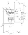
図1は、プログラミング可能な一運動自動装置(Bewegungsautomaten)の第1支持体2を第2支持体3と関節式で連結するための電動継手(電動ジョイント)1の第1実施例を示している。電動継手1は、従動軸(モータ出力軸)5を有する駆動モータ4と、駆動モータ4に対して伝動技術的に後置された歯車装置(ないし伝動装置 Getriebe)6を含んでいる。歯車装置6は、波動歯車装置(Spannungswellengetriebe, strain wave gearing)として構成されている。
FIG. 1 shows a first embodiment of an electric coupling (electric joint) 1 for articulatingly connecting a
電動継手1は、第1ハウジング部材24と第2ハウジング部材22を有する。第1ハウジング部材24は、第1支持体2と固定的に結合されており、それに対して第2ハウジング部材22は、第2支持体3と固定的に結合されている。また代替的に、第1支持体のハウジングが追加的に第1ハウジング部材としても機能し、及び/又は、第2支持体のハウジングが追加的に第2ハウジング部材としても機能することも可能である。この第1実施例において、駆動モータ4は、第1ハウジング部材24内に配設されており、それに対して歯車装置6と固定装置16は、第2ハウジング部材22内に配設されている。
The electric coupling 1 has a
歯車装置6は、駆動モータ4の従動軸5と相対回転不能に結合された駆動要素7、即ちウェーブジェネレータを有する。該ウェーブジェネレータは、半径方向に可撓(弾性変形可能)な転動ベアリング8を用い、半径方向に可撓で外歯付きのブッシュ部材9内に備えられており、ブッシュ部材9は、歯車装置6の中間要素10を構成している。駆動要素7は、楕円形に構成されており、自身の楕円形の形状を、半径方向に可撓な転動ベアリング8を介し、半径方向に可撓で外歯付きのブッシュ部材9へ伝達し、ブッシュ部材9は、楕円形の長軸に沿った互いに対峙する側面において、剛体で内歯付きの第1支持リング11と噛合係合状態にある。第1支持リング11は、第2ハウジング部材22を介して第2支持体3と相対回転不能に結合されている。第1支持リング11は、半径方向に可撓で外歯付きのブッシュ部材9と特に同じ歯数をもつことができる。
The gear unit 6 has a
更に歯車装置6は、剛体で内歯付きの第2支持リング12を有し、第2支持リング12は、同様に、半径方向に可撓で外歯付きのブッシュ部材9と噛合係合状態にある。第2支持リング12は、半径方向に可撓で外歯付きのブッシュ部材9よりも多くの歯数を有し、それにより駆動要素7の回転時には、半径方向に可撓で外歯付きのブッシュ部材9に対して第2支持リング12の相対回転が自動的に行われる。
Furthermore, the gear device 6 has a
第2支持リング12は、第1ハウジング部材24を介し、可動の第1支持体2と相対回転不能に結合されている。
The
駆動モータ4は、ステータ13とロータ14を含んでいる。ロータ14は、従動軸5と相対回転不能に結合されている。駆動モータハウジング15は、第1ハウジング部材24内で相対回転不能に固定されている。ステータ13は、駆動モータハウジング15内に定置で配設されている。
The drive motor 4 includes a
駆動モータ4を用いて駆動要素7を回転させることが可能であり、この回転は、第1支持体2と結合された第2支持リング12の相対回転をもたらし、それにより第1支持体2と第2支持体3は、互いに相対運動する。
It is possible to rotate the
電動継手1は、更に固定装置(Feststellvorrichtung)16を有し、固定装置16は、電動継手1を例えば緊急の場合及び/又は修理の場合に固定停止するように構成されて配設されている。この第1実施例では、ホルダ23を用いて第2ハウジング部材22と相対回転不能に結合された固定装置16が、中間要素10として機能する半径方向に可撓で外歯付きのブッシュ部材9へ作用する。この作用は、軸方向に可動な係止ピン18が、係止リング21として構成され且つ半径方向に可撓で外歯付きのブッシュ部材9と摩擦結合式で結合された係止手段20における切欠穴19内へ係合するかたちで実現されている。固定装置16を解除するためには、係止ピン18の自由端部が軸方向において切欠穴19から退出するように動かされる。係止手段20は、その外周部に分配された複数の切欠穴19を有し、それにより様々な回転位置で係止ピン18の係合が可能とされている。
The electric coupling 1 further comprises a fixing device (Feststellvorrichtung) 16, which is arranged and arranged for fixing the electric coupling 1 to a fixed stop, for example in case of emergency and / or repair. In this first embodiment, the fixing
図2は、プログラミング可能な運動自動装置の第1支持体2を第2支持体3と関節式で連結するための電動継手1の第2実施例を示している。この第2実施例では、駆動モータ4と、歯車装置6の一部分とが、第1ハウジング部材24内に配設され、それに対して歯車装置6の他の部分と、固定装置16が、第2ハウジング部材22内に配設されている。
FIG. 2 shows a second exemplary embodiment of an electric coupling 1 for articulating the
この第2実施例では、第1支持体2のハウジングが追加的に第1ハウジング部材24としても機能し、及び/又は、第2支持体3のハウジングが追加的に第2ハウジング部材22としても機能している。
In this second embodiment, the housing of the
図3は、プログラミング可能な運動自動装置の第1支持体2を第2支持体3と関節式で連結するための電動継手1の第3実施例を示している。この第3実施例では、歯車装置6の一部分が、第1ハウジング部材24内に配設され、それに対して駆動モータ4と、歯車装置6の他の部分と、固定装置16とが、第2ハウジング部材22内に配設されている。
FIG. 3 shows a third exemplary embodiment of an electric coupling 1 for articulating the
図4は、プログラミング可能な運動自動装置の第1支持体2を第2支持体3と関節式で連結するための電動継手1の第4実施例を示している。この第4実施例では、歯車装置6の一部分と、固定装置16とが、第1ハウジング部材24内に配設され、それに対して駆動モータ4と、歯車装置6の他の部分が、第2ハウジング部材22内に配設されている。
FIG. 4 shows a fourth exemplary embodiment of an electric coupling 1 for articulating the
この第4実施例では、第1支持体2のハウジングが追加的に第1ハウジング部材24としても機能し、及び/又は、第2支持体3のハウジングが追加的に第2ハウジング部材22としても機能している。
In this fourth embodiment, the housing of the
また固定装置16の上記の実施形態に対して代替的に、半径方向に可動な係止ピン18が、第2支持リング12と摩擦結合式で結合された係止手段20の切欠穴19へ係合することを提案することもできるであろう。そのような実施形態において、固定装置16を解除するには、係止ピン18が、例えば磁力により、半径方向で外方へ動かされ、それにより係止ピン18の自由端部と切欠穴19が係合状態から外されることになる。
As an alternative to the above-described embodiment of the fixing
固定装置16は、特に図1〜図3に示された(ホルダ23を用いた)実施形態の変形形態として、例えば、第2ハウジング部材22内に相対回転不能に配設され、第2支持体3に対して相対回転不能に配設されていることが可能であろう。従って制動過程時に発生する制動モーメントは、直接的に第2ハウジング部材22へ導かれ、歯車装置6のその他の構成部材に負荷をもたらすことはない。特に駆動モータ4の従動軸5は、制動過程時には、制動によりもたらされるトルクから切り離されている。
As a variant of the embodiment (using the holder 23) shown in FIGS. 1 to 3 in particular, the fixing
ここでも係止手段20は、その外周部に分配されて複数の切欠穴19を有することが可能であろう。それにより第2支持リング12の様々な回転位置において係止ピン18の係合が可能とされる。
Again, the locking means 20 could have a plurality of
図5は、プログラミング可能な運動自動装置の第1支持体2を第2支持体3と関節式で連結するための電動継手1の第5実施例を示している。この第5実施例では、駆動モータ4が、第1ハウジング部材24内に配設され、それに対して歯車装置6と固定装置16とが、第2ハウジング部材22内に配設されている。第1支持リング11は、第2ハウジング部材22を介して第2支持体3と固定的に結合されており、それに対して第2支持リング12は、第1ハウジング部材24を介して第1支持体2と固定的に結合されている。
FIG. 5 shows a fifth embodiment of an electric coupling 1 for articulating the
この第5実施例では、ホルダ23を用いて第2ハウジング部材22と相対回転不能に結合された固定装置16が、駆動要素7へ作用し、即ちウェーブジェネレータへ作用する。この作用は、軸方向に可動な係止ピン18が、係止リング21として構成され且つ駆動要素7と例えば摩擦結合式で結合された係止手段20における切欠穴19内へ係合するかたちで実現されている。固定装置16を解除するためには、係止ピン18の自由端部が軸方向において切欠穴19から退出するように動かされる。
In this fifth embodiment, the fixing
1 電動継手(電動ジョイント)
2 第1支持体
3 第2支持体
4 駆動モータ
5 従動軸(駆動モータの出力軸)
6 歯車装置
7 駆動要素
8 半径方向に可撓な転動ベアリング
9 半径方向に可撓で外歯付きのブッシュ部材
10 中間要素
11 第1支持リング
12 第2支持リング
13 ステータ
14 ロータ
15 駆動モータハウジング
16 固定装置
17 従動要素
18 係止ピン
19 切欠穴
20 係止手段
21 係止リング
22 第2ハウジング部材
23 ホルダ
24 第1ハウジング部材
1 Electric joint (electric joint)
2
6
Claims (18)
歯車装置の一部分がハウジング部材のうち一方のハウジング部材内に配設され、歯車装置の他の残りの部分が他方のハウジング部材内に配設されていること
を特徴とする電動継手。 Two housings, which are movable relative to one another, a drive motor and a gearing which is mechanically arranged behind the drive motor, and which are movable relative to one another in a programmable movement automatic device. An electric coupling for connecting the supports,
An electric coupling, wherein a part of the gear device is arranged in one of the housing members, and the remaining part of the gear device is arranged in the other housing member.
を特徴とする、請求項1に記載の電動継手。 An electric coupling according to claim 1, characterized in that a fixing device is provided which is constructed and arranged to lock the electric coupling.
b.固定装置は、直接的に歯車装置構成部材を制動するように構成されて配設されており、更に固定装置は、歯車装置と同じハウジング部材内か、又は少なくとも歯車装置の直接的に制動すべき構成部材と同じハウジング部材内に配設されていること
を特徴とする、請求項2に記載の電動継手。 a. The fixing device is arranged and arranged to directly brake the gear device component, or
b. The fixing device is constructed and arranged to brake the gearing component directly, and further the fixing device should be in the same housing member as the gearing or at least directly on the gearing. The electric coupling according to claim 2, wherein the electric coupling is arranged in the same housing member as the constituent members.
b.固定装置は、直接的に駆動モータか又は駆動モータの従動軸を制動するように構成されて配設されており、更に固定装置は、駆動モータと同じハウジング部材内か、又は駆動モータの従動軸と同じハウジング部材内に配設されていること
を特徴とする、請求項2に記載の電動継手。 a. The fixing device is arranged and arranged to brake the drive motor or the driven shaft of the drive motor directly, or
b. The fixing device is arranged and arranged to brake the drive motor or the driven shaft of the drive motor directly, and the fixing device is arranged in the same housing member as the drive motor or the driven shaft of the drive motor. The electric coupling according to claim 2, wherein the electric coupling is arranged in the same housing member as the above.
を特徴とする、請求項1〜4のいずれか一項に記載の電動継手。 The electric coupling according to any one of claims 1 to 4, wherein the gear device is a wave gear device.
固定装置を用いて制動可能でロック可能な歯車装置構成部材は、波動歯車装置のフレクスプラインであること、又は、
固定装置を用いて制動可能でロック可能な歯車装置構成部材は、波動歯車装置のサーキュラスプライン又はダイナミックスプラインであること
を特徴とする、請求項5に記載の電動継手。 The gear device component that can be braked and locked using the fixing device is a wave generator of a wave gear device, or
The gear device component that can be braked and locked using the fixing device is a flexspline of a wave gear device, or
The electric coupling according to claim 5, wherein the gear device component that can be braked and locked using the fixing device is a circular spline or a dynamic spline of a wave gear device.
波動歯車装置は、環状歯車装置として構成されていること
を特徴とする、請求項5又は6に記載の電動継手。 The wave gear device is configured as a pan-shaped gear device, or
7. The electric coupling according to claim 5 or 6, wherein the wave gear device is configured as an annular gear device.
を特徴とする、請求項2〜7のいずれか一項に記載の電動継手。 When the driven device generates a torque on the driven side at a value that is preset or exceeds a presettable value in the operating state, damage to components of the driven element of the wave gear device and the power transmission path The movement of a component locked directly by means of the fixing device is allowed to avoid damage to other components of the electric coupling located at The electric coupling according to any one of claims.
前記予め設定された値は、該電動継手の損傷、及び/又は歯車装置の損傷が排除されているように選択されていること
を特徴とする、請求項8に記載の電動継手。 The preset or presettable value corresponds to the maximum permissible operating torque that may occur in the component to be locked, and / or
9. The electric coupling according to claim 8, characterized in that the preset value is selected such that damage to the electric coupling and / or damage to the gearing is eliminated.
を特徴とする、請求項2〜9のいずれか一項に記載の電動継手。 10. The electric coupling according to claim 2, wherein the fixing device is configured as a friction-coupling type brake or has a friction-coupling type brake.
を特徴とする、請求項2〜10のいずれか一項に記載の電動継手。 The locking device has locking means frictionally coupled with a component that can be braked directly using the locking device, the locking means having at least one form-locking means, The shape-engaging means cooperates with a corresponding shape-engaging means that is shape-engaging and is non-rotatable relative to the housing or chassis in the actuated state of the fixing device. The electric coupling according to any one of 1.
a.固定装置は、ロック状態からリリース状態へ、又はリリース状態からロック状態へ、少なくとも一回の切替過程をもたらすために、エネルギー蓄積器内に蓄積されたエネルギーの少なくとも一部分を用いて付勢可能であること、又は、
b.固定装置は、該固定装置をロック状態又はリリース状態に保持するために、エネルギー蓄積器内に蓄積されたエネルギーの少なくとも一部分を用いて付勢可能であること、又は、
c.エネルギー蓄積器は、機械エネルギーを蓄積するように構成されていること、又は、
d.エネルギー蓄積器は、電気エネルギーを蓄積するように構成されていること
を特徴とする、請求項2〜11のいずれか一項に記載の電動継手。 The electric coupling comprises at least one energy store connected to or connectable to a fixing device,
a. The locking device is activatable with at least a portion of the energy stored in the energy store to effect at least one switching process from the locked state to the released state or from the released state to the locked state. Or
b. The securing device can be biased with at least a portion of the energy stored in the energy store to hold the securing device in a locked or released state, or
c. The energy store is configured to store mechanical energy, or
d. The electric coupling according to any one of claims 2 to 11, characterized in that the energy store is configured to store electrical energy.
固定装置は、エネルギーラインを介したエネルギー供給が遮断されている場合、エネルギー蓄積器内に蓄積されたエネルギーを使用して切替可能であること
を特徴とする、請求項12に記載の電動継手。 The electric coupling has an energy line, which transmits energy supplied from the outside for operating and / or controlling a stationary device and / or a drive motor, and
The electric coupling according to claim 12, characterized in that the fixing device is switchable using the energy stored in the energy store when the energy supply via the energy line is interrupted.
b.該電動継手は、ヒンジ継手として構成されていること、
c.該電動継手は、2つの支持体を、これらの支持体のうち一方の支持体が運動する面が、他方の支持体に対して常に直角に配設されているように連結するかたちで構成されていること
を特徴とする、請求項1〜13のいずれか一項に記載の電動継手。 a. The electric coupling connects two supports such that a surface on which one of the supports moves and a surface on which the other support moves are arranged to be always parallel to each other. Consists of, or
b. The electric coupling is configured as a hinge joint,
c. The electric coupling is formed by connecting two supports such that a surface on which one of the supports moves is always arranged at a right angle to the other support. The electric coupling according to any one of claims 1 to 13, characterized in that
を特徴とする、請求項15に記載のプログラミング可能な運動自動装置。 One of the supports is directly or indirectly coupled to the stator of the drive motor and / or the drive motor housing of the drive motor in a non-rotatable manner, and the other support is a gear unit. 16. A programmable motion automatic device according to claim 15, characterized in that it is non-rotatably connected to the driven element of.
を特徴とする、請求項15又は16に記載のプログラミング可能な運動自動装置。 The programmable motion automatic device according to claim 15 or 16 , characterized in that the two supports movably connected using the electric coupling are part of a robot arm.
a.支持体のうち一方の支持体は、ハウジング部材のうち一方のハウジング部材と固定結合されており、他方の支持体は、他方のハウジング部材と固定結合されていること、又は、
b.ハウジング部材のうち一方のハウジング部材は、支持体のうち一方の支持体であること、又は、
c.ハウジング部材のうち一方のハウジング部材は、支持体のうち一方の支持体のハウジングの構成要素であり、他方のハウジング部材は、他方の支持体のハウジングの構成要素であること
を特徴とする、請求項15〜17のいずれか一項に記載のプログラミング可能な運動自動装置。 The electric coupling has two housing members that can move relative to each other,
a. One of the supports is fixedly coupled to one of the housing members, and the other support is fixedly coupled to the other housing member, or
b. One of the housing members is one of the supports, or
c. One of the housing members is a component of the housing of one of the supports, and the other housing member is a component of the housing of the other support. 18. A programmable exercise automatic device according to any one of items 15 to 17.
Applications Claiming Priority (3)
| Application Number | Priority Date | Filing Date | Title |
|---|---|---|---|
| LU93046A LU93046B1 (en) | 2016-04-27 | 2016-04-27 | Motorized joint for a programmable motion machine |
| LU93046 | 2016-04-27 | ||
| PCT/EP2017/060054 WO2017186847A1 (en) | 2016-04-27 | 2017-04-27 | Motorized joint for a programmable automated moving device |
Publications (2)
| Publication Number | Publication Date |
|---|---|
| JP2019516046A JP2019516046A (en) | 2019-06-13 |
| JP6684923B2 true JP6684923B2 (en) | 2020-04-22 |
Family
ID=56024354
Family Applications (1)
| Application Number | Title | Priority Date | Filing Date |
|---|---|---|---|
| JP2018556270A Active JP6684923B2 (en) | 2016-04-27 | 2017-04-27 | Electric coupling for programmable motion automation |
Country Status (5)
| Country | Link |
|---|---|
| EP (1) | EP3445543B1 (en) |
| JP (1) | JP6684923B2 (en) |
| CN (1) | CN109153132A (en) |
| LU (1) | LU93046B1 (en) |
| WO (1) | WO2017186847A1 (en) |
Families Citing this family (5)
| Publication number | Priority date | Publication date | Assignee | Title |
|---|---|---|---|---|
| DE102019112023B4 (en) * | 2019-05-08 | 2022-04-21 | Franka Emika Gmbh | Braking device for a drive device of a robot |
| DE102019112029B4 (en) * | 2019-05-08 | 2022-04-21 | Franka Emika Gmbh | Method for controlling braking devices in a robotic system and robot |
| DE102019112024B4 (en) * | 2019-05-08 | 2022-04-14 | Franka Emika Gmbh | Method for controlling braking devices in a robotic system and robot |
| CN113894776A (en) * | 2021-10-12 | 2022-01-07 | 五邑大学 | High-rigidity mechanical arm and machining process |
| DE102022112242B3 (en) | 2022-05-16 | 2023-10-19 | COBOWORX GmbH | Rotary system |
Family Cites Families (7)
| Publication number | Priority date | Publication date | Assignee | Title |
|---|---|---|---|---|
| US4506590A (en) * | 1982-07-28 | 1985-03-26 | Shimadzu Coporation | Hydraulic rotary actuator |
| US4577127A (en) * | 1983-12-21 | 1986-03-18 | Westinghouse Electric Corp. | Lightweight electric robotic actuator |
| DE19956176A1 (en) * | 1999-11-22 | 2001-10-18 | Wittenstein Gmbh & Co Kg | Gripping or actuating arm |
| WO2007099511A2 (en) | 2006-03-03 | 2007-09-07 | Syddansk Universitet | Programmable robot and user interface |
| EP2828043B1 (en) * | 2012-03-21 | 2023-10-18 | B-Temia Inc. | High density actuator having a harmonic drive and a torque limiting assembly |
| CN202684913U (en) * | 2012-07-17 | 2013-01-23 | 昆山华恒焊接股份有限公司 | Six-degree-of-freedom spraying robot |
| CN204712054U (en) * | 2015-05-26 | 2015-10-21 | 广东中聪机器人科技有限公司 | A kind of robot arm |
-
2016
- 2016-04-27 LU LU93046A patent/LU93046B1/en active IP Right Grant
-
2017
- 2017-04-27 JP JP2018556270A patent/JP6684923B2/en active Active
- 2017-04-27 CN CN201780026509.5A patent/CN109153132A/en active Pending
- 2017-04-27 WO PCT/EP2017/060054 patent/WO2017186847A1/en unknown
- 2017-04-27 EP EP17718965.1A patent/EP3445543B1/en active Active
Also Published As
| Publication number | Publication date |
|---|---|
| JP2019516046A (en) | 2019-06-13 |
| CN109153132A (en) | 2019-01-04 |
| EP3445543B1 (en) | 2022-09-07 |
| LU93046B1 (en) | 2017-11-07 |
| EP3445543A1 (en) | 2019-02-27 |
| WO2017186847A1 (en) | 2017-11-02 |
Similar Documents
| Publication | Publication Date | Title |
|---|---|---|
| JP6684923B2 (en) | Electric coupling for programmable motion automation | |
| JP6758409B2 (en) | Electric fittings for programmable motion automation equipment | |
| JP4789000B2 (en) | Automatic reduction ratio switching device | |
| CN208962041U (en) | Joint of robot brake and robot at least one joint of robot brake | |
| US9447830B2 (en) | Electric brake actuator for vehicles | |
| JP2019530392A (en) | Electric actuator and final reduction ratio control device having electric actuator | |
| JP6832237B2 (en) | Bicycle electric derailleur | |
| WO2008069306A1 (en) | Joint mechanism and joint device | |
| KR20140073442A (en) | Clutch actuated by inertia mass and friction damping | |
| CN102712085B (en) | There is the manual electric tool of planetary transmission | |
| EP3369529A1 (en) | Speed-changing tool | |
| JP5872282B2 (en) | Automatic transmission and motor-driven tool | |
| JP4841584B2 (en) | Hoisting traction machine with built-in load-sensitive automatic transmission | |
| JP2013248685A (en) | Articulated body of robot | |
| TWI619334B (en) | Dual-drive electric machine having controllable planetary gear set | |
| JP2019514711A (en) | Motor-driven joint for programmable automatic motion device | |
| JP2005009373A (en) | Pitch angle control device for windmill blade | |
| US5899441A (en) | Chain hoist with a brake acting on both sides of the clutch | |
| KR101580336B1 (en) | Clutch actuator for automated manual transmission | |
| CA3150660A1 (en) | Brake system for articulated mechanism | |
| JP2016017596A (en) | Gearing-type engagement device | |
| JP7447240B2 (en) | Hybrid drive assembly with shift transmission, powertrain assembly and method of controlling powertrain assembly | |
| KR20230159551A (en) | Actuator for two clutches and hybrid transmission, and dual clutch transmission | |
| US20230382440A1 (en) | Brake device for railway vehicle | |
| JPH0357371Y2 (en) |
Legal Events
| Date | Code | Title | Description |
|---|---|---|---|
| A521 | Request for written amendment filed |
Free format text: JAPANESE INTERMEDIATE CODE: A523 Effective date: 20181226 Free format text: JAPANESE INTERMEDIATE CODE: A523 Effective date: 20181220 |
|
| A621 | Written request for application examination |
Free format text: JAPANESE INTERMEDIATE CODE: A621 Effective date: 20181220 |
|
| A131 | Notification of reasons for refusal |
Free format text: JAPANESE INTERMEDIATE CODE: A131 Effective date: 20190820 |
|
| A521 | Request for written amendment filed |
Free format text: JAPANESE INTERMEDIATE CODE: A523 Effective date: 20191115 |
|
| TRDD | Decision of grant or rejection written | ||
| A01 | Written decision to grant a patent or to grant a registration (utility model) |
Free format text: JAPANESE INTERMEDIATE CODE: A01 Effective date: 20200310 |
|
| A61 | First payment of annual fees (during grant procedure) |
Free format text: JAPANESE INTERMEDIATE CODE: A61 Effective date: 20200330 |
|
| R150 | Certificate of patent or registration of utility model |
Ref document number: 6684923 Country of ref document: JP Free format text: JAPANESE INTERMEDIATE CODE: R150 |
|
| S111 | Request for change of ownership or part of ownership |
Free format text: JAPANESE INTERMEDIATE CODE: R313113 |
|
| R350 | Written notification of registration of transfer |
Free format text: JAPANESE INTERMEDIATE CODE: R350 |
|
| R250 | Receipt of annual fees |
Free format text: JAPANESE INTERMEDIATE CODE: R250 |
|
| R250 | Receipt of annual fees |
Free format text: JAPANESE INTERMEDIATE CODE: R250 |