JP6684794B2 - Inspection equipment - Google Patents
Inspection equipment Download PDFInfo
- Publication number
- JP6684794B2 JP6684794B2 JP2017528086A JP2017528086A JP6684794B2 JP 6684794 B2 JP6684794 B2 JP 6684794B2 JP 2017528086 A JP2017528086 A JP 2017528086A JP 2017528086 A JP2017528086 A JP 2017528086A JP 6684794 B2 JP6684794 B2 JP 6684794B2
- Authority
- JP
- Japan
- Prior art keywords
- air
- mover
- component
- pair
- stator
- Prior art date
- Legal status (The legal status is an assumption and is not a legal conclusion. Google has not performed a legal analysis and makes no representation as to the accuracy of the status listed.)
- Active
Links
- 238000007689 inspection Methods 0.000 title claims description 73
- 238000013459 approach Methods 0.000 claims description 5
- 238000005192 partition Methods 0.000 claims 1
- 238000005259 measurement Methods 0.000 description 19
- 230000003068 static effect Effects 0.000 description 11
- 239000002699 waste material Substances 0.000 description 10
- 238000001514 detection method Methods 0.000 description 8
- 230000008030 elimination Effects 0.000 description 8
- 238000003379 elimination reaction Methods 0.000 description 8
- 238000000034 method Methods 0.000 description 8
- 230000005611 electricity Effects 0.000 description 6
- 239000010813 municipal solid waste Substances 0.000 description 6
- 239000000463 material Substances 0.000 description 5
- 230000008569 process Effects 0.000 description 5
- 239000000523 sample Substances 0.000 description 5
- 238000000926 separation method Methods 0.000 description 5
- 238000012546 transfer Methods 0.000 description 4
- 239000004020 conductor Substances 0.000 description 3
- 238000002474 experimental method Methods 0.000 description 2
- JEIPFZHSYJVQDO-UHFFFAOYSA-N iron(III) oxide Inorganic materials O=[Fe]O[Fe]=O JEIPFZHSYJVQDO-UHFFFAOYSA-N 0.000 description 2
- 239000000758 substrate Substances 0.000 description 2
- 229910000838 Al alloy Inorganic materials 0.000 description 1
- 241001422033 Thestylus Species 0.000 description 1
- 230000002950 deficient Effects 0.000 description 1
- 238000010586 diagram Methods 0.000 description 1
- 238000009792 diffusion process Methods 0.000 description 1
- 230000000694 effects Effects 0.000 description 1
- 230000006698 induction Effects 0.000 description 1
- 230000007246 mechanism Effects 0.000 description 1
- 229910044991 metal oxide Inorganic materials 0.000 description 1
- 150000004706 metal oxides Chemical group 0.000 description 1
- 238000012986 modification Methods 0.000 description 1
- 230000004048 modification Effects 0.000 description 1
- 238000002161 passivation Methods 0.000 description 1
- 230000000630 rising effect Effects 0.000 description 1
Images


Classifications
-
- G—PHYSICS
- G01—MEASURING; TESTING
- G01R—MEASURING ELECTRIC VARIABLES; MEASURING MAGNETIC VARIABLES
- G01R31/00—Arrangements for testing electric properties; Arrangements for locating electric faults; Arrangements for electrical testing characterised by what is being tested not provided for elsewhere
- G01R31/01—Subjecting similar articles in turn to test, e.g. "go/no-go" tests in mass production; Testing objects at points as they pass through a testing station
-
- G—PHYSICS
- G01—MEASURING; TESTING
- G01R—MEASURING ELECTRIC VARIABLES; MEASURING MAGNETIC VARIABLES
- G01R1/00—Details of instruments or arrangements of the types included in groups G01R5/00 - G01R13/00 and G01R31/00
- G01R1/02—General constructional details
- G01R1/04—Housings; Supporting members; Arrangements of terminals
- G01R1/0408—Test fixtures or contact fields; Connectors or connecting adaptors; Test clips; Test sockets
- G01R1/0416—Connectors, terminals
-
- G—PHYSICS
- G01—MEASURING; TESTING
- G01R—MEASURING ELECTRIC VARIABLES; MEASURING MAGNETIC VARIABLES
- G01R31/00—Arrangements for testing electric properties; Arrangements for locating electric faults; Arrangements for electrical testing characterised by what is being tested not provided for elsewhere
- G01R31/26—Testing of individual semiconductor devices
- G01R31/2601—Apparatus or methods therefor
-
- G—PHYSICS
- G01—MEASURING; TESTING
- G01R—MEASURING ELECTRIC VARIABLES; MEASURING MAGNETIC VARIABLES
- G01R31/00—Arrangements for testing electric properties; Arrangements for locating electric faults; Arrangements for electrical testing characterised by what is being tested not provided for elsewhere
- G01R31/28—Testing of electronic circuits, e.g. by signal tracer
- G01R31/2801—Testing of printed circuits, backplanes, motherboards, hybrid circuits or carriers for multichip packages [MCP]
- G01R31/2806—Apparatus therefor, e.g. test stations, drivers, analysers, conveyors
-
- G—PHYSICS
- G01—MEASURING; TESTING
- G01R—MEASURING ELECTRIC VARIABLES; MEASURING MAGNETIC VARIABLES
- G01R31/00—Arrangements for testing electric properties; Arrangements for locating electric faults; Arrangements for electrical testing characterised by what is being tested not provided for elsewhere
- G01R31/28—Testing of electronic circuits, e.g. by signal tracer
- G01R31/2801—Testing of printed circuits, backplanes, motherboards, hybrid circuits or carriers for multichip packages [MCP]
- G01R31/281—Specific types of tests or tests for a specific type of fault, e.g. thermal mapping, shorts testing
- G01R31/2813—Checking the presence, location, orientation or value, e.g. resistance, of components or conductors
-
- H—ELECTRICITY
- H05—ELECTRIC TECHNIQUES NOT OTHERWISE PROVIDED FOR
- H05K—PRINTED CIRCUITS; CASINGS OR CONSTRUCTIONAL DETAILS OF ELECTRIC APPARATUS; MANUFACTURE OF ASSEMBLAGES OF ELECTRICAL COMPONENTS
- H05K13/00—Apparatus or processes specially adapted for manufacturing or adjusting assemblages of electric components
- H05K13/08—Monitoring manufacture of assemblages
- H05K13/082—Integration of non-optical monitoring devices, i.e. using non-optical inspection means, e.g. electrical means, mechanical means or X-rays
-
- G—PHYSICS
- G01—MEASURING; TESTING
- G01R—MEASURING ELECTRIC VARIABLES; MEASURING MAGNETIC VARIABLES
- G01R27/00—Arrangements for measuring resistance, reactance, impedance, or electric characteristics derived therefrom
- G01R27/02—Measuring real or complex resistance, reactance, impedance, or other two-pole characteristics derived therefrom, e.g. time constant
Landscapes
- Engineering & Computer Science (AREA)
- Physics & Mathematics (AREA)
- General Physics & Mathematics (AREA)
- Microelectronics & Electronic Packaging (AREA)
- Computer Hardware Design (AREA)
- General Engineering & Computer Science (AREA)
- Operations Research (AREA)
- Manufacturing & Machinery (AREA)
- Testing Electric Properties And Detecting Electric Faults (AREA)
- Supply And Installment Of Electrical Components (AREA)
- Testing Of Individual Semiconductor Devices (AREA)
Description
本発明は、回路基板に装着される部品の検査を行う検査装置に関するものである。 The present invention relates to an inspection device for inspecting a component mounted on a circuit board.
特許文献2,3には、プローブを備え、そのプローブの接触により部品の電気的特性を測定する検査装置が記載されている。特許文献1には、保持台に載置させられた部品を両端から挟んで電気的特性を測定する検査装置が記載されている。この検査装置において、送風口部28から保持台のV溝に沿ってエアが供給され、そのV溝上にある測定後の部品が導入口部7´へ送られる。そして、不良品は廃棄され、良品は回路基板への装着に用いられる。
本発明の課題は、部品の電気的特性を自動で測定可能な検査装置において、電気的特性の測定後、測定子から良好に部品を落下させることである。 An object of the present invention is to drop a component favorably from a probe after measuring the electrical property in an inspection device capable of automatically measuring the electrical property of the component.
本発明に係る検査装置は、互いに接近・離間可能であって、部品を把持して電気的特性を測定可能な一対の測定子と、一対の測定子の互いに対向する一対の対向面の少なくとも一方にエアを供給するエア供給装置とを含む。エア供給装置により少なくとも一方の対向面にエアが供給されれば、対向面に付着した部品を良好に落下させることができる。 The inspection apparatus according to the present invention is capable of approaching / separating from each other, and at least one of a pair of stylus heads capable of gripping parts and measuring electrical characteristics, and a pair of facing surfaces of the pair of stylus heads facing each other. And an air supply device for supplying air to. If air is supplied to at least one of the facing surfaces by the air supply device, the components attached to the facing surface can be dropped well.
以下、本発明の一実施形態である検査装置を含む装着機について図面に基づいて詳細に説明する。
図1に示す装着機は、部品を回路基板に装着するものであり、装置本体2,回路基板搬送保持装置4,部品供給装置6,ヘッド移動装置8等を含む。
回路基板搬送保持装置4は、回路基板P(以下、基板Pと略称する)を水平な姿勢で搬送して保持するものであり、図1において、基板Pの搬送方向をx方向、基板Pの幅方向をy方向、基板Pの厚み方向をz方向とする。y方向、z方向は、それぞれ、装着機の前後方向、上下方向である。これら、x方向、y方向、z方向は互いに直交する。部品供給装置6は、基板Pに装着される電子部品(以下、部品と略称する)sを供給するものであり、複数のテープフィーダ14等を含む。ヘッド移動装置8は、装着ヘッド16を保持してx、y、z方向へ移動させるものであり、装着ヘッド16は、部品sを吸着して保持する吸着ノズル18を有する。Hereinafter, a mounting machine including an inspection device according to an embodiment of the present invention will be described in detail with reference to the drawings.
The mounting machine shown in FIG. 1 mounts components on a circuit board, and includes an apparatus
The circuit board transfer /
また、符号20はカメラを示す。カメラ20は、吸着ノズル18によって保持された部品sを撮像するものであり、カメラ20によって撮像された画像に基づいて、部品sが回路基板Pに装着される予定のものであるか否かが判定される。符号22は検査装置を示す。検査装置22は、部品sの電気的特性を測定して、検査するものである。部品sの電気的特性が測定され、測定された電気的特性が、JOB情報に含まれる部品sに関する情報(電気的特性)と一致するか否か、すなわち、次の作業に用いられる予定の部品sが備えた電気的特性と一致するか否かが判定されるのである。
部品sの電気的特性としては、L(インダクタンス)、C(キャパシタンス)、R(レジスタンス)、Z′(インピーダンス)等が該当し、検査装置22によってこれらのうちの1つ以上が測定される。
The electrical characteristics of the component s include L (inductance), C (capacitance), R (resistance), Z '(impedance), and the like, and the
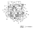
検査装置22は、ごみ箱26を介して回路基板搬送保持装置4の本体に設けられる。ごみ箱26と検査装置22とは廃棄通路28によって接続されるが、電気的特性が測定された部品sが、廃棄通路28を経てごみ箱26に収容される。検査装置22は、ごみ箱26に高さ調整可能に設けられる。図2,10に示すように、ごみ箱26には、昇降可能にベース部30が係合させられ、ベース部30に本体29がボルトおよびナットを含む締結部31(図3,4,10参照)によって固定され、これらベース部30および本体29が一体的に昇降可能に保持される。また、本体29、ベース部30には、それぞれ、廃棄通路28と連通可能な開口29a、30aが設けられる(図3,4参照)。
検査装置22は、図2〜4,10に示すように、(i)上記本体29およびベース部30、(ii)部品sを保持可能な保持台32、(iii)固定子34および可動子36から成る一対の測定子37、(iv)保持台32を移動させる保持台移動装置40、(v)可動子36を固定子34に対して接近・離間させる可動子移動装置41、(vi)電気的特性検出部としてのLCR検出部42等を含む。本実施例において、部品sは、両端部に電極を有し、一対の測定子37によって把持可能なものとすることができる。部品sとしては、例えば、角チップと称するものが該当する。The
As shown in FIGS. 2 to 4, the
保持台32は、部品載置部44と、部品載置部44を保持する載置部保持体46とを含む。部品載置部44の上面にはV溝44cが形成され、部品sが載せられる。V形状とされているため、部品sの位置が精度よく決まる。
部品載置部44は、導電性、耐摩耗性を有し、かつ、酸化が進み難い材料で製造されたものとすることができる。部品載置部44は、複数の導電性を有する部材を介してベース部30に電気的に接続されるが、ベース部30が接地されることにより、部品載置部44も接地される。本実施例においては、部品載置部44が載置部保持体46に当接し、かつ、締結部47によって固定されるとともに、載置部保持体46が本体29にストッパ80(図3参照)を介して当接し、本体29がベース部30に締結部31によって固定される。そして、載置部保持体46、ストッパ80、本体29、ベース部30、締結部31、47等は導電性を有するものである。したがって、部品載置部44は接地されるのである。
このように、部品載置部44が導電性を有する材料で製造され、かつ、接地されることにより、部品載置部44に載置させられた部品sの除電を行うことができる。また、部品載置部44が、耐摩耗性を有する材料で製造されることにより、部品載置部44の摩耗を抑制し、耐久性を向上させることができる。さらに、酸化が進み難い材料、すなわち、金属の酸化被膜である不動態皮膜が形成され得る材料で製造されることにより、部品載置部44が錆び難くすることができる。錆が部品sに付き難くすること等ができ、部品sの電気的特性の測定精度の低下を抑制することができる。例えば、部品載置部44は、アルミニウム合金またはステンレス材料等によって製造されたものとすることができる。The holding table 32 includes a
The
As described above, since the
固定子34、可動子36は、それぞれ、互いに対向する対向面34f、36fを有し、これら一対の対向面34f、36fによって部品sが把持される。固定子34は固定子保持体55を介して本体29に固定される。可動子36は、可動子保持体56に一体的に移動可能に保持されたものであり、固定子34に対して接近・離間可能とされる。本実施例において、対向面36fは、断面が三角形状を成し、V溝44cに沿って移動可能とされる。換言すれば、可動子36の対向面36fの形状は、ほぼV溝44cに対応する形状とされ、可動子36の対向面36f、固定子34の対向面34fおよび保持台32のV溝44cは、ほぼ同一高さに位置する。そのため、部品sがV溝44c内のいずれにあっても、一対の対向面34f、36fによって部品sが把持可能とされる。
また、可動子36は、本実施例において、y方向(移動方向)に伸びた長手部材であり、後退端において可動子保持体56に保持される。さらに、対向面36fを含む先端部より後部は、先端部よりx方向にはみ出す部分を有さない形状を成す。その結果、保持台32と可動子36とは互いに相対移動可能とされ、保持台32は、V溝44の底部が可動子36を下方に位置する状態で、対向面36fの前方へ移動したり後方へ移動したりすることが可能である。
さらに、可動子36と固定子34とから成る一対の測定子37、LCR検出部42、図示を省略する電源装置等を含む電気回路58が形成される。これら固定子34と可動子36との間に電流が供給されるとともに流れた電流が検出され、これらの関係に基づいて部品sの電気的特性がLCR検出部42によって測定される。LCR検出部42は、L,C,Rを検出する検出部に限らず、L,C,R,Z´等の電気的特性を表す物理量の1つ以上を検出するものとすることができる。なお、図2〜4の符号58a、bは、一対の測定子37の電気回路58への接続部である。The
In the present embodiment, the
Further, an
保持台32にはカバー部50が取り付けられる。カバー部50は、互いにx方向に隔たって、V溝44cの両側にそれぞれ設けられた一対のカバー用板部52,54を含む。カバー用板部52,54は、それぞれ、保持台32の固定子34側に設けられ、y方向およびz方向、すなわち、保持台32、可動子36の移動方向および上下方向に伸びたものであり、板状部材が曲げられた形状を成す。カバー用板部52は、平面視において溝形を成し、底板部52aと、それの両側に、x方向に隔たって設けられた側板部52b、52cとを含む。底板部52aは、下部が曲げられた形状を成し、側面視においてL字形を成し、上部において部品載置部44の固定子34側の側面に取り付けられる。また、保持台32の前進端位置において、底板部52の下部が固定子保持体55の上方に位置し、側板部52bが固定子34の外側、かつ、固定子保持体55の上方に位置し、側板部52cが側板部52bより外側であって、固定子保持体55の外側に位置する。側板部52cは、側板部52bより上下方向の寸法が大きいものであり、下端部が本体29の開口29a付近まで伸びる。カバー用板部54は、V溝44cに対してカバー用板部52の反対側の載置部保持体46に取り付けられる。カバー用板部54は、保持台32の前進端位置において、固定子保持体55の外側に位置する。カバー用板部54は、上下方向に曲げられた形状を成し、下端部が本体29の開口29a付近まで伸びたものである。
また、側板部52c、カバー用板部54のy方向の寸法は、固定子34と可動子36とが互いに離間させられる場合の少なくとも一時期に一対の対向面34f、36fの間の空間のほぼ全体をx方向から覆い得る大きさとされる。
なお、カバー部50は、後述するように、エアの拡散を防止するとともに、エアの噴出によって落下させられた部品sの飛散を防止する機能を果たす。The
Further, the dimensions of the
As will be described later, the
固定子側の部材{例えば、固定子34の上部または固定子保持体55の固定子34の上方の部分または本体29}には、可動子36の対向面36fに対向するエア通路60の開口60aが形成される。エア通路60は、図3に示すように概してy方向に伸びたエア噴出通路60s、本体29に形成された内部通路60h等を含む。エア噴出通路60sは、可動子36に近づくにつれて下方へいく向きに傾斜して伸び、可動子36が固定子34から離間した位置にある場合に、延長線kが可動子36の対向面36fの部分Rの上方または部分R内に達する状態で伸びたものである。部分Rは、可動子36の対向面36fの部品sを把持する頻度が高い部分であり、把持部と称することができる。エアは、対向面36fの延長線kが交差する部分に、斜め上方から当たる。
エア通路60には、エアシリンダ64,70が接続される。また、エア通路60のエアシリンダ64,70の下流側の部分にはイオナイザ62が設けられる。イオナイザ62は、コロナ放電を生起させて空気をイオン化するものであり、対向面36fにイオン化された空気が供給され得る。An
保持台移動装置40は、本体29またはベース部30に固定的に設けられた駆動源としてのエアシリンダ64を含む。エアシリンダ64のピストンロッド66(図5参照)には載置部保持体46が連結される。エアシリンダ64は、シリンダハウジングの内部にピストンによって仕切られた2つのエア室64a、64bを含み、2つのエア室64a、64bとエア源68、エア通路60、フィルタ(大気)との間に電磁弁装置69が設けられる。電磁弁装置69は、1つ以上の電磁弁、例えば、図5に示すように、方向切換弁、可変絞りを含むものとすることができる。方向切換弁により、載置部保持体46の移動方向が制御され、可変絞りにより載置部保持体46の移動・停止が制御される。電磁弁装置69によって、エア室64bがエア源68に連通させられエア室64aがエア通路60に連通させられることにより、保持台32が前進(図3の矢印F方向の移動)させられ、エア室64bが大気に開放されエア室64aがエア源68に連通させられることにより、保持台32が後退(図3の矢印B方向の移動)させられる。
The holding
可動子移動装置41は、本体29に固定的に設けられた駆動源としてのエアシリンダ70を含む。エアシリンダ70のピストンロッド71には可動子と一体的に移動可能な可動子保持体56が連結される。エアシリンダ70のハウジングの内部にピストンによって仕切られた2つのエア室70a、70bには、電磁弁装置72を介して、エア源68、エア通路60、フィルタ(大気)に接続される。電磁弁装置72は、1つ以上の電磁弁を含むものであり、例えば、方向切換弁、可変絞り等を含むものとすることができる。電磁弁装置72により、エア室70bがエア通路60に連通させられエア室70aがエア源68に連通させられることにより、可動子36が後退させられ、エア室70aが大気に開放されエア室70bがエア源68に連通させられることにより、可動子36が前進させられる。
本実施例においては、エアシリンダ64,70、エア通路60(エア噴出通路60sを含む)、開口60a、カバー部50、イオナイザ62等によりエア供給装置73が構成される。エア供給装置73は、可動子供給部、駆動源連動型供給部でもある。また、対向面36fが供給対象面に対応する。
なお、電磁弁装置69,72の構造は、本実施例のそれに限らない。例えば、1つの3位置弁を含むものとしたり、複数の開閉弁を含むものとしたりすること等ができる。また、イオナイザ62を設けることは不可欠ではない。The
In this embodiment, the
The structure of the
可動子保持体56と本体29との間には、y方向に伸びた一対のガイドロッド74,75が設けられ、保持台32と可動子保持体56との間には、y方向に伸びた一対のガイドロッド76,77が設けられる。ガイドロッド74,75の一端部は、可動子保持体56に連結され、他端部は、本体29に摺動可能に係合させられる。ガイドロッド76,77は、一端部において載置部保持体46に連結されるとともに、可動子保持体56に摺動可能に係合させられる。これらガイドロッド74,75、76,77により保持台32と可動子36とは本体29に対して、y方向に互いに相対移動可能とされるとともに、保持台32と可動子36とは互いにy方向に相対移動可能とされる。
また、図3に示すように、可動子保持体56の固定子側にはストッパ82が設けられ、本体29の固定子保持体55を保持する部分にはストッパ80が設けられる。ストッパ82は、可動子保持体56と保持台32(載置部保持体46)との接近限度を規定するものであり、ストッパ80は、固定子34(本体29)と保持台32(載置部保持体46)との接近限度を規定するものである。
本実施例において、ガイドロッド74〜77は、保持台移動装置40、可動子移動装置41に共有され、ストッパ80,82は保持台移動装置40の構成要素であると考えることができる。
なお、図3に示すように、可動子36が後退端位置にある場合のストッパ82の前端部と、保持台32が前進端位置にある場合の載置部保持体46との間の隙間Ldが、可動子36と保持台32との相対移動が許容される距離である。A pair of
As shown in FIG. 3, a
In the present embodiment, the
As shown in FIG. 3, a gap Ld between the front end portion of the
当該装着機は制御装置100を含む。制御装置100は、図6に示すように、コンピュータを主体とするコントローラ102と、複数の駆動回路104とを含む。コントローラ102は、実行部110、記憶部112、入出力部114等を含み、入出力部114には、基板搬送保持装置4、部品供給装置6、ヘッド移動装置8が、それぞれ、駆動回路104を介して接続されるとともに、可動子移動装置41、保持台移動装置40の電磁弁装置69,72等が接続される。また、LCR検出部42、ディスプレイ116、可動子位置センサ118、保持台位置センサ120、ノズル18の高さを検出するノズル高さセンサ122等が接続される。記憶部112には、図7(a)のフローチャートで表されるLCR検出プログラム等の複数のプログラム、テーブルが記憶されている。また、コントローラ102に設けられたタイマ124によって時間の計測が行われる。
なお、本実施例においては、制御装置100によって装着機全体が制御される場合について説明したが、基板搬送保持装置4、部品供給装置6、ヘッド移動装置8等がそれぞれ互いに個別の制御装置によって制御されるようにすることもできる。The mounting machine includes the
In this embodiment, the case where the entire mounting machine is controlled by the
以下、装着機の作動について説明する。
段取り替えが行われる場合等、新たなテープフィーダ14のセット、テープフィーダ14の交換等が行われた場合等に、そのテープフィーダ14に保持された部品sの電気的特性が測定され、そのテープフィーダ14(または部品s)が適切なものであるか否かが検査される。また、その検査結果がディスプレイ116に表示される。不適切である場合には、テープフィーダ14が取り替えられる。The operation of the mounting machine will be described below.
When a
部品sの電気的特性は、図7(a)のフローチャートで表されるLCR測定プログラムの実行により測定される。また、保持台32、可動子36の動き、保持台位置センサ120、可動子位置センサ118の状態を図7(b)に示す。
検査装置22は、常には、図9(a)に示す初期状態にある。可動子36は後退端位置にあり、保持台32は前進端位置、すなわち、ストッパ80に当接した位置にある。この状態において、保持台32は、内部導通等によりアースされた状態にある。保持台32のV溝44cの上方に可動子36が存在せず、部品sを載置可能な状態にある。また、カバー部50は固定子34の両側(x方向に隔たって)に位置する。可動子位置センサ118、保持台位置センサ120は、いずれもON状態にある。
ステップ1(以下、S1と略称する。他のステップについても同様とする)において、部品sの電気的特性の測定指令が出されたか否かが判定される。段取り替えが行われる場合等には電気的特性の測定指令が出される。測定指令が出されると、S2において、装着ヘッド16が移動させられ、例えば、新たに取り付けられたテープフィーダ14に保持された部品sが吸着ノズル18によってピックアップされて、保持台32のV溝44c上に載せられる。吸着ノズル18が下降させられ、部品sが開放されることにより、部品sがV溝44c上に載置させられたことがわかる。The electrical characteristics of the component s are measured by executing the LCR measurement program represented by the flowchart of FIG. Further, the movements of the
The
In step 1 (hereinafter abbreviated as S1; the same applies to other steps), it is determined whether or not a command to measure the electrical characteristics of the component s has been issued. When the setup is changed, a command to measure the electrical characteristics is issued. When the measurement command is issued, in S2, the mounting
そして、吸着ノズル18が部品sをV溝44c上に載置させて上昇端に達したことがノズル高さセンサ122によって検出されると、S3において、電磁弁装置72の制御により可動子36が前進させられ、可動子位置センサ118がONからOFFに切り換えられる。可動子36の先端の対向面36fは、部品載置部44のV溝44cに沿って前進させられ、対向面36fと固定子34の対向面34fとによって部品sがクランプされる{図9(b)}。本実施例においては、後退端位置から部品sをクランプするまでの可動子36のストロークL1(図3参照)は、クランプされる部品sの大きさ等で決まり、予め決められている。可動子36の前進開始時から、可動子36がストロークL1前進するまでに要する時間である前進時間が経過した後に、可変絞りの制御等により、可動子36の前進が停止させられる。前進時間は、タイマ124によって計測される。この保持台32が前進端位置にあり、可動子36が前進させられ、一対の対向面34f、36fにより部品sがクランプされた状態がクランプ状態である。Then, when it is detected by the
S4において、電磁弁装置69の制御により保持台32が後退させられ、保持台位置センサ120がONからOFFに切り換えられる。保持台32は、ストッパ82に当接するまで後退させられ{図9(c)}、その位置で保持される。その間の保持台32のストロークはL2(図3参照)である。
L2=Ld−L1
本実施例においては、ストロークL2は設定値Lx以上の大きさとされていて(L2≧Lx)、部品載置部44が部品sから設定値Lx以上離間させられる。導電性を有する部材(部品載置部44)が電気的特性の測定時に部品sの近傍に位置すると静電誘導が起きたり、渦電流が生じたりする等、電気的特性を正確に検出することができない。それに対して、部品載置部44を部品sから設定値Lx以上離間させれば(部品載置部44と部品sとの最短距離が設定値Lx以上とすれば)、部品載置部44が部品sの近傍に位置することに起因して生じる電気的特性の測定誤差を小さくすることができる。このように、設定値Lxは、部品載置部44が部品sの電気的特性の測定に影響を及ぼし難い距離であり、予め実験等により取得された値である。この状態が測定状態である。
なお、保持台32の後退開始時から、保持台32がストロークL2後退するのに要する時間である後退時間Taが経過した後に、電磁弁装置69の制御により保持台32の位置が保持される。後退時間Taは、タイマ124によって計測される。In S4, the holding table 32 is retracted by the control of the
L 2 = Ld-L 1
In the present embodiment, the stroke L 2 is set to be equal to or larger than the set value Lx (L 2 ≧ Lx), and the
It should be noted that the position of the holding table 32 is held by the control of the
S5において、吸着ノズル18により部品sが開放され、V溝44c上に載せられた時から、設定時間である除電時間が経過するのが待たれる。テープフィーダ14に保持された部品sの各々は、テープフィーダ14の運搬に伴う振動、物との接触等に起因して生じた静電気により帯電した状態にある。この帯電された部品sが、導電性を有する材料で製造され、かつ、アースされた部品載置部44に載置されることにより除電されたり、空気中への放電により除電されたりする。除電時間は、部品sが有していると推定される容量の静電気を除去するのに要する時間であり、予め実験等により求めたり、部品sの大きさ、特性等に基づいて理論的に求めたりすること等ができる。部品sが部品保持台44に載せられてからの経過時間が除電時間に達すると、S5の判定がYESとなり、S6において部品sの電気的特性が測定される。
そして、電気的特性の測定に要する時間である測定時間が経過すると、S7が実行されるのであるが、測定時間は部品sの種類等によって決まる時間としても、一定の時間としてもよい。いずれにしても予め取得されて記憶されている。In S5, it is awaited that the static elimination time, which is the set time, elapses after the component s is opened by the
When the measurement time, which is the time required to measure the electrical characteristics, elapses, S7 is executed, but the measurement time may be a time determined by the type of the component s or a fixed time. In any case, it is acquired and stored in advance.
測定時間が経過し、部品sの電気的特性の測定が終了すると、S7において、電磁弁装置72の制御により可動子36が後退させられる。後退端に達すると、可動子位置センサ118がONとなる。S8において、電磁弁装置69の制御により、保持台32が後退させられる{図9(d)}。保持台32が測定状態から後退端位置にある可動子36のストッパ82に当接するまでのストロークはL1である。そのため、保持台32がストロークL1後退するのに要する時間である後退時間Tbが経過した後に、ストッパ82に当接したとわかる。図9(d)に示すように、保持台32は、可動子36の対向面36fより後方に位置し、一対の対向面34f、36fの間の下方に存在しない。この状態が廃棄状態である。
保持台32がストッパ82に当接するまで後退させられると、S9において、電磁弁装置69の制御により、エアシリンダ64においてエア室64bがエア源68に連通させられ、エア室64aがエア通路60に連通させられる。保持台32が前進させられ、ストッパ80に当たると保持台位置センサ120がONとなる。保持台32は、一対の対向面34f、36fの間に位置し(V溝44が対向面34f、36fの間の下方に位置し)、V溝44cの上方が空間とされている。そのため、部品sが載置可能とされる。この状態が初期状態である。When the measurement time has elapsed and the measurement of the electrical characteristics of the component s is completed, the
When the holding table 32 is retracted until it comes into contact with the
可動子36の対向面36fが固定子34の対向面34fから離間することにより、これらの間に把持されていた部品sが開放される。また、可動子36の後退時には、エアシリンダ70のエア室70aがエア通路60に連通させられ、カバー用板部52,54は、それぞれ、一対の対向面34f、36fの間の空間のx方向の両側に位置する。さらに、保持台32が可動子36の対向面36fの後方に移動させられることにより、一対の対向面34f、36fの間の下方に存在しなくなり、一対の対向面34f、36fの間は、開口29a、30a、廃棄通路28に連通させられる。
可動子36の後退に伴って、エア室70aから流出させられたエアが開口60aから可動子36の対向面36fに斜め上方から供給されるが、エアが供給される空間、換言すれば、一対の対向面34f、36fの間の空間が、カバー部50によってx方向から覆われる。エアは、主として対向面36fに当たった後、対向面36fに沿って下方へ流れる。そのため、仮に、対向面36fから部品sが落下せず、部分Rに付着していても、それを良好に落下させることができる。また、エアは、カバー部50の内部を渦状に流れるため、仮に、固定子34の対向面34fに部品sが付着していたとしても落下させることができる。さらに、対向面34f、36fから落下して保持台32の上に載った部品sもエアにより落下させ得るが、仮に、V溝44上に部品sが載って、エアにより落下しなかった場合であっても、保持台32の後退に伴う可動子36の対向面36fの前進により確実に落下させることができる。このように、本実施例において、廃棄状態は、部品sが良好に落下させられた状態と考えることができる。
なお、一対の対向面34f、36fから落下した部品sは、開口29a、30a、廃棄通路28を経て良好にごみ箱26へ収容される。By separating the facing
As the
The component s dropped from the pair of facing
また、カバー部50を設けることにより、落下した部品sが飛び散らないようにすることもできる。カバー用板部52の側板部52c、カバー用板部54の下端部は本体29の開口29aの近傍まで伸びているため、部品sを良好に開口29aから廃棄通路28を経てごみ箱26へ収容させることができる。一方、イオン化されたエアが供給される場合には可動子36、固定子34の対向面36f、34fを電気的に中和させることが可能となり、次の部品sの電気的特性の測定精度を向上させることができる。
さらに、エアシリンダ64において、保持台32の前進時(S9)にエア室64aがエア噴出通路60sに連通させられる。廃棄状態から初期状態へ移行する場合にも、可動子36の対向面36fにエアを供給することができるのであり、可動子36の対向面36fの除電を良好に行うことが可能となる。Further, by providing the
Further, in the
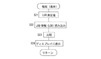
一方、測定された電気的特性とJOB情報に含まれる電気的特性とが比較され、当該部品sが、これから行われる作業(JOB)に用いられるべきものであるかどうかが判定され、その判定結果がディスプレイ116に表示される。
S21において、当該部品sの電気的特性の測定値が取得され、S22において、次のJOBのJOB情報から対応する情報が読み込まれる。S23において、これらが比較され、一致するかどうかが判定される。一致する場合であっても不一致の場合であっても、判定結果はディスプレイ116に表示される。仮に、不一致の場合には、適切なテープフィーダと交換される等の作業が行われる。On the other hand, the measured electrical characteristics and the electrical characteristics included in the JOB information are compared to determine whether or not the part s should be used for the work (JOB) to be performed from now on. Is displayed on the
In S21, the measured value of the electrical characteristic of the component s is acquired, and in S22, the corresponding information is read from the JOB information of the next JOB. In S23, these are compared and it is determined whether they match. The determination result is displayed on the
以上のように、本実施例においては、部品載置部44が導電性を有する材料で製造されるとともに接地される。その結果、電気的特性の測定前に部品載置部44に載せられた部品sの除電を良好に行うことができる。一方、部品sが帯電していると、部品sのインピーダンスを測定することが困難であった。それに対して、本実施例においては、部品sの除電が良好に行われるため、部品sのインピーダンスを良好に測定することができる。
さらに、可動子36の後退と並行して部品sを廃棄通路28に落下させることができるのであり、可動子の後退と、部品sの送出とを別の工程で行われる場合に比較して、電気的特性の測定に要する時間を短くすることができる。As described above, in this embodiment, the
Furthermore, since the part s can be dropped into the
以上のように、本実施例においては、コントローラ102のLCR測定プログラムのS4,7,8を記憶する部分、実行する部分、タイマ124、可動子位置センサ118、保持台位置センサ120等により移動制御装置、相対移動制御装置が構成される。また、そのうちの、S4を記憶する部分、実行する部分等により測定時制御部が構成され、S8を記憶する部分、実行する部分等により廃棄時制御部が構成され、S9を記憶する部分、実行する部分等により準備時制御部が構成される。移動制御装置は、保持台移動制御装置、相対移動制御部でもある。
また、エアシリンダ70が可動子用シリンダに対応し、エアシリンダ64が保持台用シリンダに対応する。エア供給装置73は、可動子供給部、駆動源連動型供給部でもある。さらに、一対の測定子37、LCR検出部42を含む電気回路58、コントローラ102のS6を記憶する部分、実行する部分等により電気的特性取得装置が構成される。
さらに、S3がクランプ工程に対応し、S4、6が測定工程に対応し、S7,8が廃棄工程に対応し、S9が準備工程に対応する。As described above, in the present embodiment, movement control is performed by the part that stores S4, 7, and 8 of the LCR measurement program of the
The
Further, S3 corresponds to the clamping process, S4 and 6 correspond to the measuring process, S7 and 8 correspond to the discarding process, and S9 corresponds to the preparing process.
なお、一対の測定子の両方を移動可能とし、保持台を本体に固定とすることもできる。その場合であっても、保持台上に載せられた部品sを一対の測定子が把持し、一対の測定子が移動させられることにより、部品sから保持台を設定値以上離間させることができる。
また、保持台は、上下方向へ移動可能とすることもできる。その場合であっても、部品sが一対の測定子によってクランプされた状態で、保持台を部品sから設定値以上離間させることができる。
さらに、エア噴出通路を検査装置22の本体29の側部に、概してx方向に開く開口を有する状態で設けることもできる。換言すれば、カバー用板部52,54のいずれか一方をなくし(例えば、カバー用板部54をなくし)、そのなくした側に、x方向に開口を有するエア噴出通路を設けることができる。その結果、エアは、対向面34f、36f(xz方向に伸びた面)に沿って、カバー用板部52に向かって供給されることになり、それにより、一対の対向面34f、36fに付着した部品sを落とすことが可能となる。
また、部品sの電気的特性の測定後に、保持台32を可動子36の後退に伴って後退させる(例えば、同時に後退させる)ことも可能である。この保持台32および可動子36が後退させられる状態を廃棄状態とすることもできる。
さらに、可動子位置センサ118、保持台位置センサ120は不可欠ではない。例えば、タイマ124による計測により電磁弁装置69,72を制御することもできる。また、エア供給装置も不可欠ではない等、本発明は、前記実施形態に記載の態様の他、当業者の知識に基づいて種々の変更、改良を施した形態で実施することができる。It should be noted that both the pair of tracing stylus can be moved and the holder can be fixed to the main body. Even in that case, the pair of gauge heads grips the component s placed on the holder, and the pair of gauge heads are moved, so that the holder can be separated from the component s by a set value or more. .
Further, the holding table may be movable in the vertical direction. Even in that case, the holding table can be separated from the component s by the set value or more in the state where the component s is clamped by the pair of tracing stylus.
Further, the air ejection passage may be provided in the side portion of the
It is also possible to move the holding table 32 backward (for example, to move backward at the same time) as the
Further, the
22:検査装置 26:ごみ箱 28:廃棄通路 29:本体 29a:開口 30:ベース部 30a:開口 31:締結部 32:保持台 34:固定子 36:可動子 34f,36f:対向面 40:保持台移動装置 41:可動子移動装置 42:LCR検出部 44:部品載置部 44c:V溝 50:カバー部 72:エア供給装置 100:制御装置 118:可動子位置センサ118:保持台位置センサ 124:タイマ
22: Inspection device 26: Trash bin 28: Waste passage 29:
(1)部品供給装置によって供給された部品をピックアップして回路基板に装着する装着機に含まれる検査装置であって、
部品を保持可能な保持台と、
互いに接近・離間可能とされるとともに、前記部品を挟んでその部品の電気的特性を測定可能な一対の測定子と、
前記保持台を移動させる保持台移動装置と、
その保持台移動装置を制御する保持台移動制御装置と
を含み、かつ、前記保持台移動制御装置が、前記一対の測定子が前記保持台に保持された前記部品を把持するクランプ状態から、前記保持台を前記部品から設定値以上離間させて、前記部品の電気的特性を測定可能な測定状態とする測定時制御部を含むことを特徴とする検査装置。
保持台は、一対の測定子の接近・離間方向と平行な方向に移動可能としても、交差する方向に移動可能としてもよい。設定値は、例えば、保持台が導電性を有するものである場合において、保持台の影響が部品の電気的特性の測定に及び難い距離とすることができる。
(2)前記保持台を、導電性を有するものとした(1)項に記載の検査装置。
(3)前記一対の測定子が、互いに対向し、前記部品に接触可能な一対の対向面を含み、それら一対の対向面が互いに接近させられることにより前記部品を保持し、互いに離間させられることにより前記部品を放すものであり、
前記保持台移動装置が、前記測定状態から、前記保持台を移動させることにより、前記互いに離間させられた一対の対向面の間の下方に前記保持台が存在しない廃棄状態とする廃棄時制御部を含む(1)項または(2)項に記載の検査装置。
(4)前記保持台移動制御装置が、前記廃棄状態から、前記互いに離間させられた一対の対向面の間の下方へ前記保持台を移動させて、前記保持台が前記部品を保持可能な初期状態とする準備時制御部を含む(3)項に記載の検査装置。
(5)前記装着機が、前記検査装置に接続された廃棄通路を含み、当該検査装置の本体が、前記廃棄通路に連通可能な開口を有する(1)項ないし(4)項のいずれか1つに記載の検査装置。
開口の位置、大きさは、少なくとも、廃棄状態において一対の対向面の間の下方に開口状態にあるように決めることができる。
(6)当該検査装置が、前記一対の測定子の間に電流を供給するとともに前記一対の測定子の間に流れる電流を検出して、前記部品の前記電気的特性を取得する電気的特性取得装置を含み、その電気的特性取得装置が、前記保持台に前記部品が載置させられた時点から設定時間以上が経過した場合に、前記部品の前記電気的特性の測定を開始する遅延型測定部を含む(1)項ないし(5)項のいずれか1つに記載の検査装置。
設定時間は、例えば、部品の除電に要する時間である除電時間とすることができる。除電時間は、部品によって決まる時間であっても、部品に関係なく予め定められた時間であってもよい。
なお、保持台に部品が載置させられている時間を除電時間とすることもできる。
(7)前記一対の測定子が、本体に固定の固定子と、前記固定子に対して相対移動可能な可動子とを含み、
当該検査装置が、前記可動子を前記固定子に対して移動させる可動子移動装置と、その可動子移動装置を制御することにより前記一対の測定子を互いに接近・離間させる可動子移動制御部とを含む(1)項ないし(6)項のいずれか1つに記載の検査装置。
(8)当該検査装置が、前記可動子と前記保持台とを互いに相対移動可能に連結する連結機構を含む(7)項に記載の検査装置。
例えば、可動子は、その可動子の移動方向と平行に伸びた長手形状を成すものとすることができる。また、保持台は、可動子の先端の前方に位置する場合、後方に位置する場合がある。
(9)前記保持台が、横断面がV字状を成す溝であるV溝を有し、前記一対の測定子の少なくとも一方の先端部の横断面が前記V溝に対応する三角形状を成す(1)項ないし(8)項のいずれか1つに記載の検査装置。(1) An inspection device included in a mounting machine that picks up a component supplied by a component supply device and mounts it on a circuit board,
A holding table that can hold parts,
A pair of stylus capable of approaching / separating from each other and capable of measuring the electrical characteristics of the part by sandwiching the part,
A holder moving device for moving the holder,
And a holding table movement control device for controlling the holding table moving device, and the holding table movement control device, from the clamp state in which the pair of measuring elements grips the component held on the holding table, An inspection apparatus comprising: a holding time control unit that separates the holding table from the component by a set value or more to bring the electrical characteristics of the component into a measurable measurement state.
The holding table may be movable in a direction parallel to the approaching / separating direction of the pair of tracing styli, or may be movable in the intersecting direction. The set value can be set to a distance at which it is difficult for the influence of the holding table to measure the electrical characteristics of the component when the holding table has conductivity, for example.
(2) The inspection device according to item (1), wherein the holding table has conductivity.
(3) The pair of tracing stylus includes a pair of facing surfaces facing each other and capable of contacting the component, and the pair of facing surfaces are held close to each other to hold the component and separate from each other. To release the parts,
When the holding table moving device moves from the measurement state, the holding table is moved to the discarding state in which the holding table does not exist below the pair of facing surfaces separated from each other. The inspection apparatus according to (1) or (2) including
(4) The holding table movement control device moves the holding table from the discarding state to a lower position between the pair of facing surfaces separated from each other, and the holding table can initially hold the component. The inspection apparatus according to item (3), including a preparatory control unit for setting a state.
(5) The mounting machine includes a waste passage connected to the inspection device, and a main body of the inspection device has an opening capable of communicating with the waste passage. (1) to (4) Inspection device described in.
The position and size of the opening can be determined so that at least in the discarding state, the opening is located below the pair of facing surfaces.
(6) Electrical property acquisition, in which the inspection device supplies a current between the pair of probes and detects a current flowing between the pair of probes to acquire the electrical properties of the component. A device that includes a device, in which the electrical characteristic acquisition device starts measurement of the electrical characteristic of the component when a preset time or more has elapsed from the time when the component was placed on the holding table, the delay-type measurement. The inspection apparatus according to any one of (1) to (5), including a part.
The set time may be, for example, a static elimination time that is a time required for static elimination of the component. The static elimination time may be a time determined by the part or a predetermined time regardless of the part.
It should be noted that the time during which the component is placed on the holding table may be the static elimination time.
(7) The pair of measuring elements includes a stator fixed to the main body, and a mover movable relative to the stator,
The inspection apparatus includes a mover moving device that moves the mover with respect to the stator, and a mover movement control unit that controls the mover moving device to move the mover closer to and away from each other. The inspection apparatus according to any one of (1) to (6), including:
(8) The inspection device according to the item (7), wherein the inspection device includes a connection mechanism that connects the mover and the holding base so as to be movable relative to each other.
For example, the mover can have a longitudinal shape extending parallel to the moving direction of the mover. Further, the holding table may be located in the front or the rear of the tip of the mover.
(9) The holding base has a V groove that is a groove having a V-shaped cross section, and the cross section of at least one tip of the pair of tracing stylus has a triangular shape corresponding to the V groove. The inspection apparatus according to any one of (1) to (8).
(10)部品供給装置によって供給された部品をピックアップして、回路基板に装着する装着機に含まれる検査装置であって、
部品を保持可能な保持台と、
互いに接近・離間可能とされ、前記部品を挟んでその部品の電気的特性を測定可能な一対の測定子と、
前記一対の測定子と前記保持台とを互いに相対移動させる相対移動装置と、
その相対移動装置を制御する相対移動制御装置と
を含み、かつ、前記相対移動制御装置が、前記一対の測定子が前記保持台に保持された前記部品を把持するクランプ状態から、前記部品と前記保持台とを設定値以上離間させて、前記部品の電気的特性を測定可能な測定状態とする測定時制御部を含むことを特徴とする検査装置。
本項に記載の検査装置には、(1)項ないし(9)項のいずれかに記載の技術的特徴を採用することができる。
相対移動装置は、(a)保持台を固定、一対の測定子を移動させる装置としたり、(b)一対の測定子のうちの一方を固定、一対の測定子の他方と保持台とを移動させる装置としたりすること等ができる。(a)の場合として、例えば、保持台に保持された部品が一対の測定子によってクランプされた状態で、一対の測定子が保持台に対して相対移動させられ、部品と保持台とが設定値以上離間させられる場合が該当する。(10) An inspection device included in a mounting machine that picks up a component supplied by a component supply device and mounts it on a circuit board,
A holding table that can hold parts,
A pair of stylus capable of approaching / separating from each other and measuring the electrical characteristics of the part with the part sandwiched therebetween,
A relative movement device that relatively moves the pair of measuring elements and the holding table,
And a relative movement control device for controlling the relative movement device, and the relative movement control device, from the clamped state in which the pair of tracing stylus grips the component held on the holding base, the component and the An inspection apparatus comprising: a measurement time control unit that separates a holding table from a set value or more to bring the electrical characteristics of the component into a measurable state.
The inspection device described in this section can employ the technical features described in any of (1) to (9).
The relative movement device is (a) a device for fixing the holding base and moving the pair of tracing stylus, or (b) fixing one of the pair of tracing stylus and moving the other of the pair of tracing stylus and the holding base. It can be used as a device for making it. In the case of (a), for example, in a state in which the part held by the holding table is clamped by the pair of measuring elements, the pair of measuring elements are moved relative to the holding table, and the parts and the holding table are set. The case where they are separated by more than the value is applicable.
(11)部品供給装置によって供給された部品をピックアップして、回路基板に装着する装着機に設けられ、(i)部品を保持可能な保持台と、(ii)互いに接近・離間可能とされ、前記部品を挟んでその部品の電気的特性を測定可能な一対の測定子とを含む検査装置において前記部品の電気的特性に関する検査を行う検査方法であって、
前記保持台に保持された部品を、一対の測定子が把持するクランプ工程と、
前記一対の測定子によって把持された前記部品から前記保持台を設定値以上離間させて、前記部品の電気的特性を測定する測定工程と
を含むことを特徴とする検査方法。
本項に記載の検査方法は、(1)項ないし(10)項のいずれかに記載の検査装置において実行され得る。
(12)前記測定工程の実行後に、前記一対の測定子を互いに離間させ、前記保持台を前記一対の測定子の互いに対向する対向面の間の下方領域から退避させる廃棄工程と、
前記保持台を、前記一対の測定子の互いに対向する対向面の間の下方へ侵入させて、前記部品を保持可能な初期状態とする準備工程と
を含む(11)項に記載の検査方法。
廃棄工程において、一対の測定子の離間と保持台の退避とを順番に行っても、並行しておこなってもよい。(11) The mounting machine that picks up the components supplied by the component supply device and mounts the components on the circuit board, and (i) a holding table that can hold the components, and (ii) be able to approach and separate from each other, A method for inspecting the electrical characteristics of the component in an inspection device that includes a pair of measuring elements capable of measuring the electrical characteristics of the component with the component interposed therebetween,
A clamping step in which the pair of tracing stylus grips the component held on the holding table,
And a step of measuring the electrical characteristics of the component by separating the holding table from the component gripped by the pair of measuring elements by a set value or more.
The inspection method described in this section can be executed by the inspection apparatus described in any of (1) to (10).
(12) A discarding step in which, after the measurement step is performed, the pair of tracing stylus are separated from each other, and the holding base is retracted from a lower region between the facing surfaces of the pair of tracing stylus facing each other,
The inspection method according to (11), further comprising: a preparatory step of intruding the holding table downward between the facing surfaces of the pair of stylus facing each other to bring the component into an initial state capable of holding the component.
In the discarding step, the separation of the pair of measuring elements and the withdrawal of the holding table may be performed in order or in parallel.
(13)部品供給装置によって供給された部品をピックアップして、回路基板に装着する装着機に含まれる検査装置であって、
導電性を有し、部品を保持する保持台と、
前記保持台に保持された前記部品を把持するとともに、前記部品が前記保持台から離間した状態で前記部品の電気的特性を取得する電気的特性取得装置と
を含むことを特徴とする検査装置。
本項に記載の検査装置は、(1)項ないし(12)項のいずれか1つに記載の技術的特徴を採用することができる。(13) An inspection device included in a mounting machine that picks up a component supplied by a component supply device and mounts it on a circuit board,
A holding table that has conductivity and holds parts,
An inspection apparatus, comprising: an electrical characteristic acquisition device that grasps the component held by the holding base and acquires an electrical characteristic of the component in a state where the component is separated from the holding base.
The inspection apparatus described in this section can employ the technical features described in any one of (1) to (12).
(14)前記一対の測定子が、互いに接近させられることにより、一対の対向面が前記部品を挟んで、その部品の電気的特性を測定し、互いに離間させられることにより、前記一対の対向面から前記部品を放すものであり、
当該検査装置が、それら一対の測定子が離間させられる場合に、前記一対の対向面のうちの少なくとも一方である供給対象面に、エアを供給するエア供給装置を含む(1)項ないし(13)項のいずれか1つに記載の検査装置。
一対の測定子が離間させられる場合とは、互いに離間している間、離間している間の一部または全行程、離間開始時、離間終了時等が該当する。
(15)前記エア供給装置が、前記エアをイオン化するイオナイザを含み、前記イオン化されたエアを前記供給対象面に供給する(14)項に記載の検査装置。
(16)前記エア供給装置が、前記供給対象面に対向する開口を有するエア通路を含む(14)項または(15)項に記載の検査装置。
供給対象面が一対の対向面の一方である場合には、その一方の供給対象面に対向する開口が1つ設けられ、供給対象面が一対の対向面の両方である場合には、それぞれに対向して開口が2つ設けられる。
(17)前記エア通路が、前記供給対象面に近づくにつれて下方へ行く向きに傾斜したエア噴出通路を含む(16)項に記載の検査装置。
(18)前記エア噴出通路の傾斜角度が、前記エアが前記供給対象面の前記部品を把持する部分の上方に当たる角度とされた(17)項に記載の検査装置。
(19)前記一対の測定子が、本体に固定の固定子と、その固定子に接近・離間可能な可動子とを含み、
前記エア供給装置が、前記可動子が前記固定子から離間させられる場合に、前記供給対象面である前記可動子の対向面に前記エアを供給する可動子供給部を含む(14)項ないし(18)項のいずれか1つに記載の検査装置。
(20)当該検査装置が、可動子用シリンダを備え、その可動子用シリンダの作動により前記可動子を前記固定子に対して接近・離間させる可動子移動装置を含み、
前記エア供給装置が、前記可動子の前記固定子からの離間に伴って前記可動子用シリンダから流出させられるエアを前記可動子の対向面に供給する駆動源連動型供給部を含む(19)項に記載の検査装置。
(21)当該検査装置が、前記一対の対向面が離間した状態で、これらの間を覆うカバー部を含む(1)項ないし(20)項のいずれか1つに記載の検査装置。
カバー部は、一対の対向面の間の大部分を覆うものであり、一対の対向面の間の全体を覆うものとする必要は必ずしもなく、多少の隙間がある状態で覆うものであってもよい。一対の対向面が互いに離間させられる場合の少なくとも一時期に一対の対向面の間の全体を両側から覆うものとすることが望ましい。
(22)前記カバー部が、前記保持台に取り付けられ、前記保持台が後退端位置にある状態で、前記一対の対向面の間の大部分を側から覆うものである(21)項に記載の検査装置。(14) When the pair of measuring elements are brought close to each other, the pair of facing surfaces sandwich the component, measure the electrical characteristics of the component, and are separated from each other, so that the pair of facing surfaces are spaced from each other. To release the parts from
The inspection apparatus includes an air supply device that supplies air to at least one of the pair of opposing surfaces when the pair of gauge heads are separated from each other, the surface to be supplied (1) to (13). ) The inspection device according to any one of paragraphs.
The case where the pair of tracing stylus are separated corresponds to the case where the stylus is separated from each other, a part or the whole process during the separation, the start of separation, the end of separation, and the like.
(15) The inspection apparatus according to (14), wherein the air supply device includes an ionizer that ionizes the air, and supplies the ionized air to the supply target surface.
(16) The inspection device according to item (14) or (15), wherein the air supply device includes an air passage having an opening facing the surface to be supplied.
When the supply target surface is one of the pair of opposing surfaces, one opening is provided to face the one supply target surface, and when the supply target surface is both of the pair of opposing surfaces, Two openings are provided facing each other.
(17) The inspection apparatus according to the item (16), wherein the air passage includes an air ejection passage that is inclined downward toward the supply target surface.
(18) The inspection device according to (17), wherein the inclination angle of the air ejection passage is an angle at which the air hits above a portion of the supply target surface that grips the component.
(19) The pair of measuring elements includes a stator fixed to the main body and a mover capable of approaching and separating from the stator,
The air supply device includes a mover supply unit that supplies the air to a surface of the mover facing the supply target surface when the mover is separated from the stator (14) to (14). The inspection apparatus according to any one of 18).
(20) The inspection device includes a mover moving device that includes a mover cylinder, and moves the mover toward and away from the stator by operating the mover cylinder.
The air supply device includes a drive source interlocking type supply unit that supplies air, which is caused to flow out from the mover cylinder with the separation of the mover from the stator, to an opposing surface of the mover (19). The inspection apparatus according to item.
(21) The inspection device according to any one of items (1) to (20), wherein the inspection device includes a cover portion that covers the pair of opposed surfaces in a state of being separated from each other.
The cover part covers most of the space between the pair of facing surfaces, and does not necessarily cover the entire space between the pair of facing surfaces, and may cover the space with some clearance. Good. It is desirable that the entire space between the pair of facing surfaces be covered from both sides at least once when the pair of facing surfaces are separated from each other.
(22) The cover part is attached to the holding table and covers most of the space between the pair of facing surfaces from the side when the holding table is at the retracted end position. Inspection equipment.
Claims (7)
互いに接近させられることにより、一対の対向面が前記部品を挟んで、その部品の電気的特性を測定し、互いに離間させられることにより、前記一対の対向面から前記部品を放す一対の測定子と、
それら一対の測定子が離間させられる場合に、前記一対の対向面のうちの少なくとも一方である供給対象面にエアを供給するエア供給装置と
を含むことを特徴とする検査装置。 It is installed in the mounting machine that picks up the components supplied by the component supply device and mounts them on the circuit board.
By being brought close to each other, a pair of facing surfaces sandwich the component, the electrical characteristics of the component are measured, and by being separated from each other, a pair of tracing stylus that releases the component from the pair of facing surfaces. ,
An inspection apparatus, comprising: an air supply device that supplies air to at least one of the pair of facing surfaces, the surface to be supplied when the pair of measuring elements are separated.
前記エア供給装置が、前記一方の供給対象面に対向する開口を有するエア通路を含む請求項1または2に記載の検査装置。 The supply target surface is one of the pair of opposing surfaces,
The inspection apparatus according to claim 1, wherein the air supply device includes an air passage having an opening facing the one supply target surface.
前記エア通路が、固定子側の部材に設けられ、前記供給対象面である前記可動子の対向面に対向する開口を有するものであり、
前記エア供給装置が、前記可動子が前記固定子から離間させられる場合に、前記固定子側の部材に設けられた前記エア通路の前記開口から前記供給対象面にエアを供給する可動子供給部を含む請求項3または4に記載の検査装置。 The pair of measuring elements includes a stator fixed to the main body, and a mover that can approach and separate from the stator,
The air passage is provided in a member on the stator side, and has an opening facing the facing surface of the mover that is the surface to be supplied,
The air supply device, wherein when the movable member is moved away from the stator, the mover supply unit for supplying air to the supply target surface from the opening of said air passage provided in member stator side The inspection apparatus according to claim 3 or 4, which includes:
前記可動子用シリンダが、ハウジングと、前記ハウジングの内部を第1エア室と第2エア室とに仕切るピストンとを含み、
前記可動子移動装置が、前記電磁弁装置により、前記第2エア室が前記エア源に連通させられ、前記第1エア室が前記固定子側の部材に設けられた前記エア通路に連通させられることにより、前記可動子を前記固定子から離間させるものであり、
前記エア供給装置が、前記可動子用シリンダを備え、前記電磁弁装置により、前記第2エア室が前記エア源に連通させられ、前記第1エア室が前記固定子側の部材に設けられた前記エア通路に連通させられることにより、前記可動子の前記固定子からの離間に伴って、前記可動子用シリンダの前記第1エア室から前記固定子側の部材に設けられた前記エア通路に流出させられたエアを前記開口から前記可動子の対向面に供給する駆動源連動型供給部を含む請求項5に記載の検査装置。 The inspection device includes (a) an air source, (b) a solenoid valve device, and (c) a mover cylinder connected to the air source and the air passage via the solenoid valve device , A mover moving device that moves the mover toward and away from the stator by operating a mover cylinder;
The mover cylinder includes a housing, and a piston that partitions the interior of the housing into a first air chamber and a second air chamber,
In the mover moving device, the second air chamber is made to communicate with the air source and the first air chamber is made to communicate with the air passage provided in the member on the stator side by the electromagnetic valve device. By doing so, the mover is separated from the stator,
The air supply device includes the mover cylinder, the electromagnetic valve device allows the second air chamber to communicate with the air source, and the first air chamber is provided in a member on the stator side. By being communicated with the air passage, as the mover is separated from the stator, the air passage provided in a member on the stator side from the first air chamber of the mover cylinder. The inspection apparatus according to claim 5, further comprising a drive source interlocking type supply unit configured to supply the outflowing air from the opening to the facing surface of the mover.
Priority Applications (1)
| Application Number | Priority Date | Filing Date | Title |
|---|---|---|---|
| JP2020059755A JP6912620B2 (en) | 2015-07-15 | 2020-03-30 | Inspection equipment |
Applications Claiming Priority (1)
| Application Number | Priority Date | Filing Date | Title |
|---|---|---|---|
| PCT/JP2015/070307 WO2017009986A1 (en) | 2015-07-15 | 2015-07-15 | Inspection device |
Related Child Applications (1)
| Application Number | Title | Priority Date | Filing Date |
|---|---|---|---|
| JP2020059755A Division JP6912620B2 (en) | 2015-07-15 | 2020-03-30 | Inspection equipment |
Publications (2)
| Publication Number | Publication Date |
|---|---|
| JPWO2017009986A1 JPWO2017009986A1 (en) | 2018-04-19 |
| JP6684794B2 true JP6684794B2 (en) | 2020-04-22 |
Family
ID=57758013
Family Applications (1)
| Application Number | Title | Priority Date | Filing Date |
|---|---|---|---|
| JP2017528086A Active JP6684794B2 (en) | 2015-07-15 | 2015-07-15 | Inspection equipment |
Country Status (5)
| Country | Link |
|---|---|
| US (1) | US10509069B2 (en) |
| EP (1) | EP3324721B1 (en) |
| JP (1) | JP6684794B2 (en) |
| CN (1) | CN107736086B (en) |
| WO (1) | WO2017009986A1 (en) |
Families Citing this family (4)
| Publication number | Priority date | Publication date | Assignee | Title |
|---|---|---|---|---|
| CN110268816B (en) | 2017-02-14 | 2021-03-16 | 株式会社富士 | Measurement device and measurement method |
| CN112424621B (en) * | 2018-07-20 | 2023-11-14 | 株式会社富士 | Measuring device |
| JP7142210B2 (en) * | 2018-10-15 | 2022-09-27 | パナソニックIpマネジメント株式会社 | Characteristic measuring device, component mounting device, characteristic measuring method, and component mounting method |
| JP7101832B2 (en) * | 2021-01-27 | 2022-07-15 | 株式会社Fuji | Measuring device, mounting machine |
Family Cites Families (19)
| Publication number | Priority date | Publication date | Assignee | Title |
|---|---|---|---|---|
| JPS5230703A (en) | 1975-09-04 | 1977-03-08 | Koichi Ogiso | Process and apparatus for treating molten metal by convection |
| DE3143941C2 (en) * | 1981-11-05 | 1983-09-15 | Deutsche Thomson-Brandt Gmbh, 7730 Villingen-Schwenningen | Device for a component placement machine for feeding polarized electronic components |
| US4721907A (en) * | 1985-01-23 | 1988-01-26 | Universal Instruments Corporation | Apparatus for automated testing of surface mounted components |
| JPS61179600A (en) * | 1985-01-30 | 1986-08-12 | 三菱電機株式会社 | Electronic component mounting apparatus |
| JPS62114289A (en) * | 1985-11-14 | 1987-05-26 | 松下電器産業株式会社 | Mounting of electronic parts and apparatus for the same |
| JPH0176100U (en) | 1987-11-11 | 1989-05-23 | ||
| JPH05294437A (en) * | 1992-04-21 | 1993-11-09 | Matsushita Electric Ind Co Ltd | Parts feeder |
| JPH08250897A (en) * | 1995-03-13 | 1996-09-27 | Advantest Corp | Mounter with electric characteristic inspecting function |
| JP3287744B2 (en) * | 1995-08-12 | 2002-06-04 | ティーディーケイ株式会社 | Method and apparatus for measuring characteristics of electronic components |
| JP3339390B2 (en) * | 1997-11-12 | 2002-10-28 | 株式会社村田製作所 | Electronic component transfer device |
| SG98373A1 (en) * | 1998-11-25 | 2003-09-19 | Advantest Corp | Device testing apparatus |
| JP4107008B2 (en) * | 2002-08-14 | 2008-06-25 | 株式会社村田製作所 | Electronic component characteristic measuring device |
| JP2005000725A (en) * | 2003-06-09 | 2005-01-06 | Murata Mfg Co Ltd | Electronic part sorting apparatus |
| JP2008166663A (en) * | 2007-01-05 | 2008-07-17 | Denso Corp | Apparatus and method for holding printed circuit board |
| JP5918622B2 (en) * | 2012-05-11 | 2016-05-18 | ヤマハ発動機株式会社 | Component or board working device and component mounting device |
| JP5852505B2 (en) * | 2012-05-14 | 2016-02-03 | ヤマハ発動機株式会社 | Component or board working device and component mounting device |
| WO2014155657A1 (en) | 2013-03-29 | 2014-10-02 | 富士機械製造株式会社 | Electronic component mounting machine and measurement method |
| JP6272325B2 (en) * | 2013-06-18 | 2018-01-31 | 富士機械製造株式会社 | Mounting management device, mounting processing device, mounting system, mounting management method and mounting processing method |
| EP3021654B1 (en) * | 2013-07-08 | 2019-04-03 | FUJI Corporation | Component holding state detection method and component mounting machine |
-
2015
- 2015-07-15 JP JP2017528086A patent/JP6684794B2/en active Active
- 2015-07-15 EP EP15898298.3A patent/EP3324721B1/en active Active
- 2015-07-15 WO PCT/JP2015/070307 patent/WO2017009986A1/en active Application Filing
- 2015-07-15 CN CN201580081482.0A patent/CN107736086B/en active Active
- 2015-07-15 US US15/743,541 patent/US10509069B2/en active Active
Also Published As
| Publication number | Publication date |
|---|---|
| US20180203057A1 (en) | 2018-07-19 |
| WO2017009986A1 (en) | 2017-01-19 |
| CN107736086A (en) | 2018-02-23 |
| CN107736086B (en) | 2020-05-01 |
| EP3324721A4 (en) | 2018-07-18 |
| JPWO2017009986A1 (en) | 2018-04-19 |
| US10509069B2 (en) | 2019-12-17 |
| EP3324721B1 (en) | 2022-05-18 |
| EP3324721A1 (en) | 2018-05-23 |
Similar Documents
| Publication | Publication Date | Title |
|---|---|---|
| JP6684795B2 (en) | Inspection equipment | |
| JP6607719B2 (en) | Inspection device | |
| JP6684794B2 (en) | Inspection equipment | |
| JP7035256B2 (en) | Mounting machine | |
| CN107926155B (en) | Inspection apparatus | |
| JP6568733B2 (en) | Inspection device | |
| JP6771256B2 (en) | Inspection equipment | |
| JP7398177B2 (en) | Electronic component mounting machine | |
| JP6852127B2 (en) | Inspection equipment and inspection method | |
| JP2020096205A (en) | Inspection device | |
| JP7203273B2 (en) | Mounting machine | |
| JP6908676B2 (en) | Electrical property acquisition method and component mounting method | |
| JP7155445B2 (en) | Mounting machine | |
| JP7013617B2 (en) | Mounting machine | |
| JP7570396B2 (en) | Placement machine | |
| JP7164924B2 (en) | Electronic component mounting machine and inspection method | |
| JP2023024733A (en) | Loading machine | |
| JP6675410B2 (en) | Inspection device |
Legal Events
| Date | Code | Title | Description |
|---|---|---|---|
| A621 | Written request for application examination |
Free format text: JAPANESE INTERMEDIATE CODE: A621 Effective date: 20180608 |
|
| A131 | Notification of reasons for refusal |
Free format text: JAPANESE INTERMEDIATE CODE: A131 Effective date: 20190723 |
|
| A521 | Request for written amendment filed |
Free format text: JAPANESE INTERMEDIATE CODE: A523 Effective date: 20190909 |
|
| TRDD | Decision of grant or rejection written | ||
| A01 | Written decision to grant a patent or to grant a registration (utility model) |
Free format text: JAPANESE INTERMEDIATE CODE: A01 Effective date: 20200303 |
|
| A61 | First payment of annual fees (during grant procedure) |
Free format text: JAPANESE INTERMEDIATE CODE: A61 Effective date: 20200330 |
|
| R150 | Certificate of patent or registration of utility model |
Ref document number: 6684794 Country of ref document: JP Free format text: JAPANESE INTERMEDIATE CODE: R150 |
|
| R250 | Receipt of annual fees |
Free format text: JAPANESE INTERMEDIATE CODE: R250 |
|
| R250 | Receipt of annual fees |
Free format text: JAPANESE INTERMEDIATE CODE: R250 |