JP6679249B2 - Drive device for vehicle opening and closing body - Google Patents
Drive device for vehicle opening and closing body Download PDFInfo
- Publication number
- JP6679249B2 JP6679249B2 JP2015174801A JP2015174801A JP6679249B2 JP 6679249 B2 JP6679249 B2 JP 6679249B2 JP 2015174801 A JP2015174801 A JP 2015174801A JP 2015174801 A JP2015174801 A JP 2015174801A JP 6679249 B2 JP6679249 B2 JP 6679249B2
- Authority
- JP
- Japan
- Prior art keywords
- wire
- outer tube
- drum
- opening
- groove
- Prior art date
- Legal status (The legal status is an assumption and is not a legal conclusion. Google has not performed a legal analysis and makes no representation as to the accuracy of the status listed.)
- Active
Links
Images


Classifications
-
- E—FIXED CONSTRUCTIONS
- E05—LOCKS; KEYS; WINDOW OR DOOR FITTINGS; SAFES
- E05F—DEVICES FOR MOVING WINGS INTO OPEN OR CLOSED POSITION; CHECKS FOR WINGS; WING FITTINGS NOT OTHERWISE PROVIDED FOR, CONCERNED WITH THE FUNCTIONING OF THE WING
- E05F11/00—Man-operated mechanisms for operating wings, including those which also operate the fastening
- E05F11/38—Man-operated mechanisms for operating wings, including those which also operate the fastening for sliding windows, e.g. vehicle windows, to be opened or closed by vertical movement
- E05F11/48—Man-operated mechanisms for operating wings, including those which also operate the fastening for sliding windows, e.g. vehicle windows, to be opened or closed by vertical movement operated by cords or chains or other flexible elongated pulling elements, e.g. tapes
- E05F11/481—Man-operated mechanisms for operating wings, including those which also operate the fastening for sliding windows, e.g. vehicle windows, to be opened or closed by vertical movement operated by cords or chains or other flexible elongated pulling elements, e.g. tapes for vehicle windows
- E05F11/483—Man-operated mechanisms for operating wings, including those which also operate the fastening for sliding windows, e.g. vehicle windows, to be opened or closed by vertical movement operated by cords or chains or other flexible elongated pulling elements, e.g. tapes for vehicle windows by cables
-
- E—FIXED CONSTRUCTIONS
- E05—LOCKS; KEYS; WINDOW OR DOOR FITTINGS; SAFES
- E05F—DEVICES FOR MOVING WINGS INTO OPEN OR CLOSED POSITION; CHECKS FOR WINGS; WING FITTINGS NOT OTHERWISE PROVIDED FOR, CONCERNED WITH THE FUNCTIONING OF THE WING
- E05F15/00—Power-operated mechanisms for wings
-
- E—FIXED CONSTRUCTIONS
- E05—LOCKS; KEYS; WINDOW OR DOOR FITTINGS; SAFES
- E05F—DEVICES FOR MOVING WINGS INTO OPEN OR CLOSED POSITION; CHECKS FOR WINGS; WING FITTINGS NOT OTHERWISE PROVIDED FOR, CONCERNED WITH THE FUNCTIONING OF THE WING
- E05F15/00—Power-operated mechanisms for wings
- E05F15/60—Power-operated mechanisms for wings using electrical actuators
- E05F15/603—Power-operated mechanisms for wings using electrical actuators using rotary electromotors
- E05F15/665—Power-operated mechanisms for wings using electrical actuators using rotary electromotors for vertically-sliding wings
- E05F15/689—Power-operated mechanisms for wings using electrical actuators using rotary electromotors for vertically-sliding wings specially adapted for vehicle windows
- E05F15/697—Motor units therefor, e.g. geared motors
-
- F—MECHANICAL ENGINEERING; LIGHTING; HEATING; WEAPONS; BLASTING
- F16—ENGINEERING ELEMENTS AND UNITS; GENERAL MEASURES FOR PRODUCING AND MAINTAINING EFFECTIVE FUNCTIONING OF MACHINES OR INSTALLATIONS; THERMAL INSULATION IN GENERAL
- F16H—GEARING
- F16H19/00—Gearings comprising essentially only toothed gears or friction members and not capable of conveying indefinitely-continuing rotary motion
- F16H19/02—Gearings comprising essentially only toothed gears or friction members and not capable of conveying indefinitely-continuing rotary motion for interconverting rotary or oscillating motion and reciprocating motion
- F16H19/06—Gearings comprising essentially only toothed gears or friction members and not capable of conveying indefinitely-continuing rotary motion for interconverting rotary or oscillating motion and reciprocating motion comprising flexible members, e.g. an endless flexible member
- F16H19/0622—Gearings comprising essentially only toothed gears or friction members and not capable of conveying indefinitely-continuing rotary motion for interconverting rotary or oscillating motion and reciprocating motion comprising flexible members, e.g. an endless flexible member for converting reciprocating movement into oscillating movement and vice versa, the reciprocating movement is perpendicular to the axis of oscillation
- F16H19/0628—Gearings comprising essentially only toothed gears or friction members and not capable of conveying indefinitely-continuing rotary motion for interconverting rotary or oscillating motion and reciprocating motion comprising flexible members, e.g. an endless flexible member for converting reciprocating movement into oscillating movement and vice versa, the reciprocating movement is perpendicular to the axis of oscillation the flexible member, e.g. a cable, being wound with one string to a drum and unwound with the other string to create reciprocating movement of the flexible member
-
- F—MECHANICAL ENGINEERING; LIGHTING; HEATING; WEAPONS; BLASTING
- F16—ENGINEERING ELEMENTS AND UNITS; GENERAL MEASURES FOR PRODUCING AND MAINTAINING EFFECTIVE FUNCTIONING OF MACHINES OR INSTALLATIONS; THERMAL INSULATION IN GENERAL
- F16H—GEARING
- F16H19/00—Gearings comprising essentially only toothed gears or friction members and not capable of conveying indefinitely-continuing rotary motion
- F16H19/02—Gearings comprising essentially only toothed gears or friction members and not capable of conveying indefinitely-continuing rotary motion for interconverting rotary or oscillating motion and reciprocating motion
- F16H19/06—Gearings comprising essentially only toothed gears or friction members and not capable of conveying indefinitely-continuing rotary motion for interconverting rotary or oscillating motion and reciprocating motion comprising flexible members, e.g. an endless flexible member
- F16H19/0645—Gearings comprising essentially only toothed gears or friction members and not capable of conveying indefinitely-continuing rotary motion for interconverting rotary or oscillating motion and reciprocating motion comprising flexible members, e.g. an endless flexible member the flexible push or pull member having guiding means, i.e. the flexible member being supported at least partially by a guide to transmit the reciprocating movement
-
- E—FIXED CONSTRUCTIONS
- E05—LOCKS; KEYS; WINDOW OR DOOR FITTINGS; SAFES
- E05Y—INDEXING SCHEME RELATING TO HINGES OR OTHER SUSPENSION DEVICES FOR DOORS, WINDOWS OR WINGS AND DEVICES FOR MOVING WINGS INTO OPEN OR CLOSED POSITION, CHECKS FOR WINGS AND WING FITTINGS NOT OTHERWISE PROVIDED FOR, CONCERNED WITH THE FUNCTIONING OF THE WING
- E05Y2201/00—Constructional elements; Accessories therefore
- E05Y2201/10—Covers; Housings
-
- E—FIXED CONSTRUCTIONS
- E05—LOCKS; KEYS; WINDOW OR DOOR FITTINGS; SAFES
- E05Y—INDEXING SCHEME RELATING TO HINGES OR OTHER SUSPENSION DEVICES FOR DOORS, WINDOWS OR WINGS AND DEVICES FOR MOVING WINGS INTO OPEN OR CLOSED POSITION, CHECKS FOR WINGS AND WING FITTINGS NOT OTHERWISE PROVIDED FOR, CONCERNED WITH THE FUNCTIONING OF THE WING
- E05Y2201/00—Constructional elements; Accessories therefore
- E05Y2201/60—Suspension or transmission members; Accessories therefore
- E05Y2201/622—Suspension or transmission members elements
- E05Y2201/644—Flexible elongated pulling elements; Members cooperating with flexible elongated pulling elements
- E05Y2201/654—Cables
-
- E—FIXED CONSTRUCTIONS
- E05—LOCKS; KEYS; WINDOW OR DOOR FITTINGS; SAFES
- E05Y—INDEXING SCHEME RELATING TO HINGES OR OTHER SUSPENSION DEVICES FOR DOORS, WINDOWS OR WINGS AND DEVICES FOR MOVING WINGS INTO OPEN OR CLOSED POSITION, CHECKS FOR WINGS AND WING FITTINGS NOT OTHERWISE PROVIDED FOR, CONCERNED WITH THE FUNCTIONING OF THE WING
- E05Y2201/00—Constructional elements; Accessories therefore
- E05Y2201/60—Suspension or transmission members; Accessories therefore
- E05Y2201/622—Suspension or transmission members elements
- E05Y2201/644—Flexible elongated pulling elements; Members cooperating with flexible elongated pulling elements
- E05Y2201/658—Members cooperating with flexible elongated pulling elements
- E05Y2201/66—Deflectors; Guides
-
- E—FIXED CONSTRUCTIONS
- E05—LOCKS; KEYS; WINDOW OR DOOR FITTINGS; SAFES
- E05Y—INDEXING SCHEME RELATING TO HINGES OR OTHER SUSPENSION DEVICES FOR DOORS, WINDOWS OR WINGS AND DEVICES FOR MOVING WINGS INTO OPEN OR CLOSED POSITION, CHECKS FOR WINGS AND WING FITTINGS NOT OTHERWISE PROVIDED FOR, CONCERNED WITH THE FUNCTIONING OF THE WING
- E05Y2201/00—Constructional elements; Accessories therefore
- E05Y2201/60—Suspension or transmission members; Accessories therefore
- E05Y2201/622—Suspension or transmission members elements
- E05Y2201/644—Flexible elongated pulling elements; Members cooperating with flexible elongated pulling elements
- E05Y2201/658—Members cooperating with flexible elongated pulling elements
- E05Y2201/664—Drums
-
- E—FIXED CONSTRUCTIONS
- E05—LOCKS; KEYS; WINDOW OR DOOR FITTINGS; SAFES
- E05Y—INDEXING SCHEME RELATING TO HINGES OR OTHER SUSPENSION DEVICES FOR DOORS, WINDOWS OR WINGS AND DEVICES FOR MOVING WINGS INTO OPEN OR CLOSED POSITION, CHECKS FOR WINGS AND WING FITTINGS NOT OTHERWISE PROVIDED FOR, CONCERNED WITH THE FUNCTIONING OF THE WING
- E05Y2201/00—Constructional elements; Accessories therefore
- E05Y2201/60—Suspension or transmission members; Accessories therefore
- E05Y2201/622—Suspension or transmission members elements
- E05Y2201/71—Toothed gearing
-
- E—FIXED CONSTRUCTIONS
- E05—LOCKS; KEYS; WINDOW OR DOOR FITTINGS; SAFES
- E05Y—INDEXING SCHEME RELATING TO HINGES OR OTHER SUSPENSION DEVICES FOR DOORS, WINDOWS OR WINGS AND DEVICES FOR MOVING WINGS INTO OPEN OR CLOSED POSITION, CHECKS FOR WINGS AND WING FITTINGS NOT OTHERWISE PROVIDED FOR, CONCERNED WITH THE FUNCTIONING OF THE WING
- E05Y2900/00—Application of doors, windows, wings or fittings thereof
- E05Y2900/50—Application of doors, windows, wings or fittings thereof for vehicles
- E05Y2900/53—Application of doors, windows, wings or fittings thereof for vehicles characterised by the type of wing
- E05Y2900/531—Doors
-
- E—FIXED CONSTRUCTIONS
- E05—LOCKS; KEYS; WINDOW OR DOOR FITTINGS; SAFES
- E05Y—INDEXING SCHEME RELATING TO HINGES OR OTHER SUSPENSION DEVICES FOR DOORS, WINDOWS OR WINGS AND DEVICES FOR MOVING WINGS INTO OPEN OR CLOSED POSITION, CHECKS FOR WINGS AND WING FITTINGS NOT OTHERWISE PROVIDED FOR, CONCERNED WITH THE FUNCTIONING OF THE WING
- E05Y2900/00—Application of doors, windows, wings or fittings thereof
- E05Y2900/50—Application of doors, windows, wings or fittings thereof for vehicles
- E05Y2900/53—Application of doors, windows, wings or fittings thereof for vehicles characterised by the type of wing
- E05Y2900/55—Windows
Landscapes
- Engineering & Computer Science (AREA)
- General Engineering & Computer Science (AREA)
- Mechanical Engineering (AREA)
- Power-Operated Mechanisms For Wings (AREA)
- Window Of Vehicle (AREA)
- Lock And Its Accessories (AREA)
Description
本発明は車両に搭載される開閉体の駆動装置に関する。 The present invention relates to a drive device for an opening / closing body mounted on a vehicle.
ウインドガラスを昇降させるウインドレギュレータや、スライドドアを開閉させるドア開閉装置などの自動車用の開閉体の駆動装置では、ワイヤを巻回した巻取ドラムの回転によってワイヤを移動(牽引、弛緩)させて開閉体(ウインドガラスやスライドドア)を駆動する構造が多用されている。巻取ドラムの外周面にはワイヤを巻回する螺旋溝が形成されている。巻取ドラムを収容するドラムハウジングには筒状のアウタチューブの端部が接続し、巻取ドラムの螺旋溝から延出されたワイヤがドラムハウジング内の通路を通ってアウタチューブ内の挿通穴に進退可能に挿入される。 In a drive device for an opening / closing body for an automobile, such as a window regulator that raises / lowers a window glass or a door opening / closing device that opens / closes a sliding door, the wire is moved (pulled or loosened) by rotation of a winding drum around which the wire is wound. The structure that drives the opening / closing body (window glass or sliding door) is often used. A spiral groove around which the wire is wound is formed on the outer peripheral surface of the winding drum. The end of the cylindrical outer tube is connected to the drum housing that houses the take-up drum, and the wire extended from the spiral groove of the take-up drum passes through the passage in the drum housing to the insertion hole in the outer tube. It is inserted so that it can move forward and backward.
この種の駆動装置では、巻取ドラムが回転すると螺旋溝の傾斜に応じてワイヤが巻取ドラムの回転軸方向に振れる。その際にワイヤの振れ量(振れ角)が大きいと、アウタチューブの端面部分で挿通穴の縁に対してワイヤが干渉し、駆動の繰り返しによってワイヤがダメージを受けるおそれがある。その対策として、ドラムハウジングとは別部材としてアウタチューブの端部を挿入可能なブッシュ部材を設け、このブッシュ部材内にアウタチューブの端部から離れるにつれて徐々に内径を大きくする振れ止め用の穴を形成し、ブッシュ部材を介してアウタチューブをドラムハウジングに接続させる構造が知られている(特許文献1)。巻取ドラムが回転するときに振れ止め用の穴の内面によってワイヤの振れ角が制限され、ワイヤを保護することができる。 In this type of driving device, when the winding drum rotates, the wire swings in the rotation axis direction of the winding drum according to the inclination of the spiral groove. At this time, if the deflection amount (deflection angle) of the wire is large, the wire may interfere with the edge of the insertion hole at the end surface portion of the outer tube, and the wire may be damaged by repeated driving. As a countermeasure against this, a bush member that can insert the end of the outer tube is provided as a member separate from the drum housing, and a steady hole that gradually increases the inner diameter with increasing distance from the end of the outer tube is provided in the bush member. A structure is known in which the outer tube is formed and connected to the drum housing via a bush member (Patent Document 1). When the winding drum rotates, the deflection angle of the wire is limited by the inner surface of the steady hole, so that the wire can be protected.
特許文献1のワイヤの振れ止め構造は、ドラムハウジングとは別にブッシュ部材を取り付ける必要があるため、ドラムハウジングに対して直接にアウタチューブを接続させる構成に比して、組み立ての工数が多くなって製造に手間がかかったり、部品点数の増加によってコスト高になってしまったりするおそれがある。 In the wire steadying structure of Patent Document 1, a bush member needs to be attached separately from the drum housing, so that the number of assembling steps is increased as compared with the configuration in which the outer tube is directly connected to the drum housing. It may take time to manufacture and the cost may increase due to an increase in the number of parts.
本発明は以上の問題に鑑みてなされたものであり、生産性が良く安価でありながらワイヤの耐久性向上を実現できる車両用開閉体の駆動装置を提供することを目的とする。 The present invention has been made in view of the above problems, and an object of the present invention is to provide a drive device for an opening / closing body for a vehicle, which can improve the durability of the wire while having high productivity and low cost.
本発明は、ワイヤを挿通する挿通穴を有するアウタチューブと、周面に形成した螺旋溝にワイヤが巻回される円柱状のドラムと、収容部にドラムを回転可能に支持し、アウタチューブ接続部にアウタチューブの端部を挿入させ、アウタチューブ接続部と収容部の間のワイヤ通過部にワイヤを通過させるドラムハウジングと、ドラムハウジングに取り付けられてドラムを回転させる駆動部材を備え、ワイヤの駆動によって開閉体を開閉させる車両用開閉体の駆動装置において、以下の特徴を有するものである。ドラムハウジングまたは駆動部材に、ドラムの回転軸方向に沿う第1の方向へのワイヤの振れを制限する第1の振れ止め部と、第1の方向と反対の第2の方向へのワイヤの振れを制限する第2の振れ止め部を設ける。第1の振れ止め部と第2の振れ止め部は、ドラムの回転軸方向において、螺旋溝の形成範囲の一端とアウタチューブ接続部に接続したアウタチューブの端部における挿通穴の形成範囲の一端とを結ぶ線と、螺旋溝の形成範囲の他端とアウタチューブ接続部に接続したアウタチューブの端部における挿通穴の形成範囲の他端とを結ぶ線とで囲まれる領域の内側に設けられる。 The present invention relates to an outer tube having an insertion hole through which a wire is inserted, a cylindrical drum in which the wire is wound around a spiral groove formed on a peripheral surface, and a drum rotatably supported in an accommodating portion to connect the outer tube. A drum housing for inserting the end portion of the outer tube into the portion and passing the wire through a wire passing portion between the outer tube connecting portion and the accommodating portion; and a drive member attached to the drum housing for rotating the drum. A drive device for an opening / closing body for a vehicle, which opens and closes the opening / closing body by driving, has the following features. The drum housing or the drive member has a first steadying portion that restricts a wire swing in a first direction along a rotation axis direction of the drum, and a wire swing in a second direction opposite to the first direction. And a second steady rest for limiting The first steady rest and the second steady rest are, in the rotation axis direction of the drum, one end of the forming range of the spiral groove and one end of the forming range of the insertion hole at the end of the outer tube connected to the outer tube connecting part. And a line connecting the other end of the spiral groove formation range and the other end of the insertion hole formation range at the end of the outer tube connected to the outer tube connection portion. .
本発明の一態様として、ワイヤ通過部を第1の方向に開口するワイヤ通過溝とした上で、ワイヤ通過溝内に第1の振れ止め部を設け、ワイヤ通過溝の側面と第1の振れ止め部の間に、開口を通したワイヤの挿脱を可能にさせる隙間を形成する。この隙間は、第1の振れ止め部が設けられている部分でワイヤ通過溝の開口の幅を拡大して形成するとよい。 One aspect of the present invention, after the wire passage groove for exposing the wire passage portion in a first direction, the first bracing section provided in the wire passage groove, deflection side of the wire passage groove and the first during the stop portion, that form a gap which allows the insertion and removal of the wire through the opening. This gap, and in part the first bracing section is provided to form an enlarged width of the opening of the wire passage groove.
本発明の別の態様として、ワイヤ通過部を第1の方向に開口するワイヤ通過溝とし、収容部も第1の方向に開口するようにドラムハウジングを構成した上で、ワイヤ通過溝の長手方向で第1の振れ止め部と第2の振れ止め部の位置を異ならせ、ワイヤ通過溝には開口に対向する第2の方向の底部のうち少なくとも第1の振れ止め部に対応する位置に貫通穴を形成する。このように構成したドラムハウジングは、第1の方向と第2の方向(ドラムの回転軸方向)に相対移動する型によって容易に製造可能となる。 As another aspect of the present invention , the wire passing portion is formed as a wire passing groove that opens in the first direction, and the drum housing is configured so that the housing portion also opens in the first direction, and then the longitudinal direction of the wire passing groove. in a first bracing section at different positions of the second bracing section, the wire passage grooves through a position corresponding to at least a first bracing section of the bottom of the second direction opposite to the opening form a hole. The drum housing configured as described above can be easily manufactured by a mold that relatively moves in the first direction and the second direction (the rotation axis direction of the drum).
以上の本発明の車両用開閉体の駆動装置によれば、ドラムを収容するドラムハウジングまたはドラムを駆動する駆動部材に設けた振れ止め部(第1の振れ止め部と第2の振れ止め部)によってドラムの回転軸方向のワイヤの振れを制限し、部品点数が少なく安価で生産性に優れた構成によって、確実にワイヤの耐久性を向上させることができる。 According to the above-described drive device for an opening / closing body for a vehicle of the present invention, the steady rests (first steady rest and second steady rest) provided on the drum housing that houses the drum or the drive member that drives the drum. The wire swing in the rotation axis direction of the drum is limited by the configuration, and the durability of the wire can be reliably improved by the configuration having a small number of parts and being inexpensive and excellent in productivity.
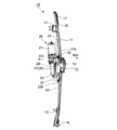
以下、本発明の車両用開閉体の駆動装置として、ドアの窓開口を開閉するウインドガラス(開閉体)を駆動させるウインドレギュレータに適用した実施形態を説明する。図1ないし図3に示すウインドレギュレータ10は、車両のドアパネル(図示略)内に取り付けられてウインドガラス(図示略)を昇降させるものである。図3にはウインドレギュレータ10を車両のドアに取り付けた状態での車外側と車内側の向きを矢線で示している。ウインドレギュレータ10は長尺部材であるガイドレール11を有し、ガイドレール11は長手方向に位置を異ならせて設けたブラケット12,13を介してドアパネル(インナパネル)に固定される。この固定状態でガイドレール11はその長手方向を概ね車両の高さ方向に向けて配される。
Hereinafter, an embodiment applied to a window regulator for driving a window glass (opening / closing body) that opens and closes a window opening of a door will be described as a drive device for a vehicle opening / closing body of the present invention. The
ウインドガラスを支持するスライダベース14(ガラスキャリア)がガイドレール11の長手方向に沿って移動可能に支持されている。スライダベース14には一対のワイヤ15,16(図2)のそれぞれの一端が接続されている。ガイドレール11の長手方向の一端付近にはプーリブラケット30が固定されており、プーリブラケット30上にガイドプーリ17がプーリ支持軸19を介して回転可能に支持されている。ワイヤ15はスライダベース14からガイドレール11に沿って該ガイドレール11の一端方向に延び、ガイドプーリ17の外周面上に形成したワイヤガイド溝によって支持される。ワイヤ15の進退に応じてガイドプーリ17はプーリ支持軸19を中心とする回転を行う。ガイドレール11の長手方向の他端付近にはワイヤガイド部材18が設けられており、ワイヤ16はスライダベース14からガイドレール11に沿って該ガイドレール11の他端に向けて延びてワイヤガイド部材18に案内される。ワイヤガイド部材18はガイドレール11に対して固定されており、ワイヤガイド部材18に形成したワイヤガイド溝に沿って進退可能にワイヤ16が支持される。
A slider base 14 (glass carrier) that supports the window glass is movably supported along the longitudinal direction of the
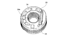
ガイドプーリ17とワイヤガイド部材18から出たワイヤ15,16は、管状のアウタチューブ21,22内に挿通され、アウタチューブ21,22が接続されるドラムハウジング20内に設けた巻取ドラム23に巻回される。図7と図8に示すように巻取ドラム23は円柱状をなし、その中心部には軸線方向に貫通する軸嵌合穴24が形成されている。軸嵌合穴24の内面には鋸刃状のセレーションが形成されている。巻取ドラム23の外周面にはワイヤ15,16が巻回される螺旋溝25が形成されている。螺旋溝25は巻取ドラム23の外周面に沿って旋回しながら巻取ドラム23の軸線方向に位置を変化させる。巻取ドラム23の軸線方向における螺旋溝25の形成範囲Hを図8に示した。
The
ドラムハウジング20に対してモータユニット(駆動部材)26(図1ないし図3)が取り付けられる。モータユニット26は、モータ27と、モータ27の出力軸の回転を減速させながら伝達する減速ギヤ列を内蔵したギヤボックス28と、ギヤボックス28の減速ギヤ列を経由してモータ27の回転駆動力が伝達される嵌合軸(図示略)が設けられている。モータユニット26は後述するドラムハウジング20の開口部分を覆うカバー部29を有しており、嵌合軸はカバー部29から突出して巻取ドラム23の軸嵌合穴24に嵌合する。嵌合軸には軸嵌合穴24のセレーションに嵌合するセレーションが形成されており、この嵌合状態でモータ27を駆動すると嵌合軸と共に巻取ドラム23が回転する。
A motor unit (driving member) 26 (FIGS. 1 to 3) is attached to the
アウタチューブ21は一端がプーリブラケット30に接続し、他端がドラムハウジング20に接続しており、両端位置が定められたアウタチューブ21内でワイヤ15が進退可能となる。アウタチューブ22は一端がワイヤガイド部材18に接続し、他端がドラムハウジング20に接続しており、両端位置が定められたアウタチューブ22内でワイヤ16が進退可能となる。アウタチューブ21,22内には長手方向に貫通する挿通穴50(図9)が形成されており、ワイヤ15、16は挿通穴50に挿入される。アウタチューブ21でプーリブラケット30に接続する側の端部をレール側端部21aとし、アウタチューブ22でワイヤガイド部材18に接続する側の端部をレール側端部22aとする。また、アウタチューブ21,22のそれぞれでドラムハウジング20側に接続する側の端部をドラム側端部21b,22bとする。
One end of the
ドラムハウジング20はドアパネル(インナパネル)に固定される。モータ27の駆動力によって巻取ドラム23が正逆に回転すると、ワイヤ15,16の一方が巻取ドラム23の螺旋溝25への巻回量を大きくし、他方が巻取ドラム23の螺旋溝25から繰り出されて、この一対のワイヤ15,16の牽引と弛緩の関係によってスライダベース14がガイドレール11に沿って移動する。スライダベース14の移動に応じてウインドガラスが昇降する。
The
以下、アウタチューブ21,22が接続するドラムハウジング20について説明する。図4ないし図6に示すように、ドラムハウジング20は、ドラム収容部(収容部)31と一対のアウタチューブ挿入部32,33を有している。ドラム収容部31は、底部34とその周縁に形成した円筒状の立壁35によって囲まれる空間を形成しており、底部34の反対側は収容部開口36として開口している。底部34にはドラム支持座37(図5)が設けられている。巻取ドラム23は、一端をドラム支持座37上に載せてドラム収容部61内に挿入される。ドラム支持座37には円筒状の軸突起37a(図5)が設けられ、巻取ドラム23には軸嵌合穴24の一部に平滑な円筒面24a(図7)が形成されている。軸突起37aが円筒面24aに挿入され、軸突起37aに対して円筒面24aを摺接させることで巻取ドラム23が回転可能に支持される。ドラム収容部61への収容状態での巻取ドラム23の回転中心である回転軸23xを図5と図6に一点鎖線で示した。モータ27の駆動力が伝達されると、回転軸23xを中心として巻取ドラム23が回転する。
Hereinafter, the
ドラムハウジング20にはドラム収容部31に連通するワイヤ通過溝(ワイヤ通過部)40とワイヤ通過溝(ワイヤ通過部)41が互いに異なる方向(ウインドレギュレータ10の完成状態でのプーリブラケット30とワイヤガイド部材18の方向)に向けて形成されており、ワイヤ通過溝40の先端にアウタチューブ挿入部32が設けられ、ワイヤ通過溝41の先端にアウタチューブ挿入部33が設けられている。
In the
ワイヤ通過溝40とワイヤ通過溝41は略同じ構成を有しており、ワイヤ通過溝40とワイヤ通過溝41に共通する要素は図中で同じ符号を用いて示している。ワイヤ通過溝40,41はそれぞれ, ドラム収容部31から回転軸23xと交差する(略直交する)方向に向突出する溝状の部位であり、ドラム収容部31の底部34に連続する底部42と、底部42から回転軸23xに沿う方向(立壁35の突出方向)に立ち上げられた一対の側壁43,44を有している。底部42に対向する天面部分には通過溝開口45が形成されている。通過溝開口45はドラム収容部31の収容部開口36に連続する開口部である。
The
アウタチューブ挿入部32にはアウタチューブ21のドラム側端部21bを挿入可能であり、アウタチューブ挿入部33にはアウタチューブ22のドラム側端部22bを挿入可能である。アウタチューブ挿入部32に対するドラム側端部21bの挿入方向である挿入軸32xと、アウタチューブ挿入部33に対するドラム側端部22bの挿入方向である挿入軸33xを図6に示した。
The
アウタチューブ挿入部32とアウタチューブ挿入部33は略同じ構成を有しており、アウタチューブ挿入部32とアウタチューブ挿入部33に共通する要素は図中で同じ符号を用いて示している。アウタチューブ挿入部32,33の内部には挿入軸32x,33xの方向に貫通する挿通溝46が形成されている。挿通溝46は、ワイヤ通過溝40,41に連通しており、ワイヤ通過溝40,41と挿通溝46の境界付近に段差状の挿入規制面47が形成されている。アウタチューブ挿入部32,33に挿入されたアウタチューブ21,22のドラム側端部21b,22bの端面がそれぞれ挿入規制面47に当接して、アウタチューブ挿入部32,33へのアウタチューブ21,22の挿入位置が決まる(図9参照)。ワイヤ通過溝40,41の通過溝開口45は、アウタチューブ挿入部32,33まで連続して形成されている。アウタチューブ挿入部32,33における通過溝開口45の幅はアウタチューブ21,22の径よりも小さく、アウタチューブ挿入部32,33に挿入されたアウタチューブ21,22のドラム側端部21b,22bは、通過溝開口45を通して脱落しないようになっている。
The outer
ウインドレギュレータ10の組み立て時には、アウタチューブ21,22のドラム側端部21b,22bの端面から突出するワイヤ15,16を、通過溝開口45を通してアウタチューブ挿入部32,33の挿通溝46とワイヤ通過溝40,41内に挿入すると共に、ドラム側端部21b,22bを挿入軸32x,33xに沿ってアウタチューブ挿入部32,33の挿通溝46内に挿入する。ドラム側端部21b,22bの端面が挿入規制面47に当接して挿入軸32x,33x方向でのアウタチューブ21,22の位置が定まる。ワイヤ15,16は、ワイヤ通過溝40,41を通ってドラム収容部31内へ導かれて、巻取ドラム23の外周面上の螺旋溝25に巻回される。このようにして組み付けた状態(図1ないし図3、図9)で、ワイヤ15,16はアウタチューブ21,22に対して挿通穴50(図9)内を進退可能となり、巻取ドラム23の回転に応じて螺旋溝25へのワイヤ15,16の巻回量が変化する。
At the time of assembling the
さらにドラムハウジング20の天面側にモータユニット26取り付ける。モータユニット26のカバー部29がドラムハウジング20の収容部開口36と通過溝開口45を塞ぎ、ドラム収容部31からの巻取ドラム23の脱落を防止する。モータユニット26を取り付けることで、前述の通りモータユニット26側の嵌合軸(不図示)が軸嵌合穴24に嵌合して、モータ27の駆動力を巻取ドラム23に伝達可能となる。
Further, the
以上のようにワイヤ15,16を配策したウインドレギュレータ10では、巻取ドラム23が回転すると、螺旋溝25からの各ワイヤ15,16の繰り出し位置が回転軸23xに沿う方向で変化する。この回転軸23xに沿う方向のワイヤ15,16の振れを制限する振れ止め手段として、ドラムハウジング20はワイヤ通過溝40とワイヤ通過溝41のそれぞれに第1振れ止め部(振れ止め部、第1の振れ止め部)51と第2振れ止め部(振れ止め部、第2の振れ止め部)52を備えている。
In the
図9に、回転軸23x方向における、巻取ドラム23の螺旋溝25の形成範囲H(図8)の一端D1と他端D2、アウタチューブ22のドラム側端部22bの挿通穴50の形成範囲の一端E1と他端E2を示した。螺旋溝25側の一端D1と挿通穴50側の一端E1を結ぶ仮想線をF1、螺旋溝25側の他端D2と挿通穴50側の他端E2を結ぶ仮想線をF2とする。図9に示すように、ドラムハウジング20内でワイヤ16は、巻取ドラム23(螺旋溝25)とアウタチューブ22のドラム側端部22b(挿通穴50)により支持され、その間のワイヤ通過溝41では巻取ドラム23やアウタチューブ22の支持を受けていない。そのため、振れ止め手段を設けない場合には、仮想線F1と仮想線F2で囲まれる範囲(振れ可能範囲Mとする)でワイヤ16の振れが生じる可能性がある。図9はワイヤ16とワイヤ通過溝41の関係を示しているが、ワイヤ15とワイヤ通過溝40も同様の関係にある。
In FIG. 9, one end D1 and the other end D2 of the forming range H (FIG. 8) of the
第1振れ止め部51は側壁43に設けた突出部であり、回転軸23xに沿う方向で、仮想線F1よりも振れ可能範囲Mの内側に入った位置に設けられている(図9参照)。また、図6のように回転軸23xに沿って見たときに、ワイヤ通過溝40の第1振れ止め部51は挿入軸32xと重なる位置にあり、ワイヤ通過溝41の第1振れ止め部51は挿入軸32xと重なる位置にある。そのため、ワイヤ通過溝40内で挿入軸32xに沿って配策されたワイヤ15と、ワイヤ通過溝41内で挿入軸33xに沿って配策されたワイヤ16はいずれも、第1振れ止め部51によって回転軸23xに沿う一方の振れ量が制限される。具体的には、振れ可能範囲Mの仮想線F1よりも狭い範囲(仮想線F2寄りの位置)に振れ量が制限される。
The first
第2振れ止め部52は底部42に設けた突出部であり、回転軸23xに沿う方向で、仮想線F2よりも振れ可能範囲Mの内側に入った位置に設けられている(図9参照)。そのため、ワイヤ通過溝40内に配策されたワイヤ15と、ワイヤ通過溝41内に配策されたワイヤ16はいずれも、第2振れ止め部52によって回転軸23xに沿う他方の振れ量が制限される。具体的には、振れ可能範囲Mの仮想線F2よりも狭い範囲(仮想線F1寄りの位置)に振れ量が制限される。
The second
このように第1振れ止め部51と第2振れ止め部52によって回転軸23xに沿う方向のワイヤ15,16の振れ量(振れ角)を制限することで、ワイヤ15,16の耐久性を向上させることができる。特に、振れ可能範囲Mが最も狭くなっているアウタチューブ21,22(ドラム側端部21b,22b)の挿通穴50への挿入部分において、挿通穴50の縁部に対するワイヤ15,16の擦れを効果的に防ぐことができる。このワイヤ15,16の振れ制限は、ドラムハウジング20に形成した第1振れ止め部51と第2振れ止め部52によって実現されるので、振れ止め用の部材や機構を別途備える必要がなく、構成が簡略で低コストに得ることができる。
In this way, by limiting the deflection amount (deflection angle) of the
第1振れ止め部51と第2振れ止め部52は、ワイヤ通過溝40,41の長手方向(ワイヤ15,16の延設方向)において、巻取ドラム23よりもアウタチューブ21,22のドラム側端部21b,22bに近い位置に配されている。この配置は、ワイヤ15,16の擦れが生じやすいアウタチューブ21,22の挿通穴50の縁部に近い位置でワイヤ15,16の振れ幅を管理できる利点がある。
The first steadying
回転軸23xに沿う方向に収容部開口36と通過溝開口45を開口させたドラムハウジング20は、回転軸23xに沿う方向に相対移動する2つの金型によって製造することが好ましい。ここで、ワイヤ通過溝40,41の長手方向で第1振れ止め部51と第2振れ止め部52が互いに位置を異ならせている。さらにワイヤ通過溝40,41の底部42には、回転軸23xに沿う方向で第1振れ止め部51に対向する位置に貫通穴53が形成されている。このように構成することにより、回転軸23xに沿う方向に相対移動する2つの金型によって第1振れ止め部51と第2振れ止め部52も併せて形成することが可能となるため、ドラムハウジング20の生産性が向上する。
The
図6に示すように、第1振れ止め部51が形成されている部分ではワイヤ通過溝40,41の通過溝開口45の幅が広げられており、第1振れ止め部51と側壁44の間に隙間45a(図6)が形成されている。そのため、第1振れ止め部51に妨げられずに、隙間45aを通してワイヤ通過溝40,41内へワイヤ15,16を挿入させることが可能である。図4と図5に示すように、第1振れ止め部51は、隙間45a側にワイヤ15,16を導きやすくする傾斜方向のテーパ面51aを有している。
As shown in FIG. 6, the width of the
以上、図示実施形態に基づき本発明を説明したが、本発明は図示した実施形態に限定されるものではなく、発明の要旨を逸脱しない限りにおいて改良や改変が可能である。例えば図示実施形態では、第1振れ止め部51と第2振れ止め部52をいずれもドラムハウジング20に設けているが、ドラムハウジング20に対して組み付けられるモータユニット26に少なくとも一つの抜け止めを設けることもできる。具体的には、モータユニット26のカバー部29は通過溝開口45を塞ぐ(ワイヤ通過溝40,41の一部を構成する)形状を有しているため、第1振れ止め部51に相当する振れ止め部をドラムハウジング20ではなくカバー部29に設ける変更が可能である。
The present invention has been described above based on the illustrated embodiments, but the present invention is not limited to the illustrated embodiments, and improvements and modifications can be made without departing from the spirit of the invention. For example, in the illustrated embodiment, both the first
図示実施形態では、ワイヤ通過溝40,41の側壁43に第1振れ止め部51を突設しているが、反対側の側壁44に第1振れ止め部51を設けることも可能である。
In the illustrated embodiment, the first
図示実施形態のドラムハウジング20は、ドラム収容部31の収容部開口36とワイヤ通過溝40,41の通過溝開口45が同じ方向に開口しているが、収容部開口36と通過溝開口45が回転軸23xに沿う方向で互いに反対に向けて開口するタイプのドラムハウジングにも適用可能である。
In the
図示実施形態では、巻取ドラム23の回転軸23xに沿う方向のうち第1の方向(通過溝開口45の開口方向)へのワイヤ15,16の振れを制限する第1振れ止め部51と、これと反対の第2の方向(ワイヤ通過溝40,41の底部42の方向)へのワイヤ15,16の振れを制限する第2振れ止め部52を備えている。この構成は、巻取ドラム23の回転によってワイヤ15,16がいずれの方向に振れても保護できるので優れているが、本発明は回転軸23xに沿う方向のうち一方にのみワイヤ15,16の振れを制限するような構成であっても成立する。
In the illustrated embodiment, a first
また、図示実施形態ではドラムハウジング20におけるワイヤ通過溝40とワイヤ通過溝41が略共通の構造であり、各ワイヤ15,16に同等の大きさの振れが生じ得る条件であるため、ワイヤ通過溝40とワイヤ通過溝41の両方に共通構造の第1振れ止め部51と第2振れ止め部52を設けているが、ワイヤ15とワイヤ16で振れ量の条件(図9の振れ可能範囲Mの幅)などが異なる場合は、ワイヤ通過溝40に設ける振れ止め部とワイヤ通過溝41に設ける振れ止め部のスペック(形状、配置)を異ならせてもよい。
Further, in the illustrated embodiment, the
10 ウインドレギュレータ
11 ガイドレール
12 13 ブラケット
14 スライダベース
15 16 ワイヤ
17 ガイドプーリ
18 ワイヤガイド部材
19 プーリ支持軸
20 ドラムハウジング
21 22 アウタチューブ
21a 22a レール側端部
21b 22b ドラム側端部
23 巻取ドラム
23x 軸線
24 軸嵌合穴
25 螺旋溝
26 モータユニット(駆動部材)
27 モータ
28 ギヤボックス
29 カバー部
30 プーリブラケット
31 ドラム収容部(収容部)
32 33 アウタチューブ挿入部
32x 33x 挿入軸
34 底部
35 立壁
36 収容部開口
37 ドラム支持座
40 41 ワイヤ通過溝(ワイヤ通過部)
42 底部
43 44 側壁
45 通過溝開口
45a 隙間
46 挿通溝
47 挿入規制面
50 挿通穴
51 第1振れ止め部(振れ止め部、第1の振れ止め部)
51a テーパ面
52 第2振れ止め部(振れ止め部、第2の振れ止め部)
53 貫通穴
D1 螺旋溝の形成範囲の一端
D2 螺旋溝の形成範囲の他端
E1 アウタチューブの挿通穴の形成範囲の一端
E2 アウタチューブの挿通穴の形成範囲の他端
F1 F2 振れ可能範囲を決める仮想線
H 螺旋溝の形成範囲
M 振れ可能範囲
10
27
32 33 outer
42
51a Tapered
53 Through hole D1 One end D2 of spiral groove formation range One end E1 of spiral groove formation range One end E2 of outer tube insertion hole formation range Other end F1 of outer tube insertion hole formation range F1 F2 Virtual line H Spiral groove formation range M Swing range
Claims (3)
上記ワイヤを挿通する挿通穴を有するアウタチューブ;
周面に螺旋溝が形成され、該螺旋溝に上記ワイヤが巻回される円柱状のドラム;
上記ドラムを回転可能に支持する収容部と、上記アウタチューブの端部を挿入可能なアウタチューブ接続部と、上記アウタチューブ接続部と上記収容部の間で上記ワイヤを通過させるワイヤ通過部とを有するドラムハウジング;
上記ドラムハウジングに取り付けられ上記ドラムを回転させる駆動部材;及び
上記ドラムハウジングまたは上記駆動部材に設けられ、上記ドラムの上記回転軸方向に沿う第1の方向への上記ワイヤの振れを制限する第1の振れ止め部と、上記第1の方向と反対の第2の方向への上記ワイヤの振れを制限する第2の振れ止め部;
を備え、
上記第1の振れ止め部と上記第2の振れ止め部は、上記回転軸方向における、上記螺旋溝の形成範囲の一端と上記アウタチューブ接続部に接続した上記アウタチューブの端部における上記挿通穴の形成範囲の一端とを結ぶ線と、上記螺旋溝の形成範囲の他端と上記アウタチューブ接続部に接続した上記アウタチューブの端部における上記挿通穴の形成範囲の他端とを結ぶ線とで囲まれる領域の内側に設けられ、
上記ワイヤ通過部は上記第1の方向に開口するワイヤ通過溝であり、上記ワイヤ通過溝内に上記第1の振れ止め部が設けられており、
上記ワイヤ通過溝の側面と上記第1の振れ止め部の間に、上記開口を通した上記ワイヤの挿脱を可能にさせる隙間が形成されていることを特徴とする車両用開閉体の駆動装置。 In a drive device for a vehicle opening / closing body that opens and closes the opening / closing body by driving a wire,
An outer tube having an insertion hole through which the wire is inserted;
A cylindrical drum in which a spiral groove is formed on the peripheral surface and the wire is wound around the spiral groove;
An accommodating part that rotatably supports the drum, an outer tube connecting part into which the end of the outer tube can be inserted, and a wire passing part that passes the wire between the outer tube connecting part and the accommodating part. A drum housing having;
A drive member attached to the drum housing for rotating the drum; and a first member provided on the drum housing or the drive member for restricting deflection of the wire in a first direction along the rotation axis direction of the drum. A steady rest and a second steady rest that limits the runout of the wire in a second direction opposite the first direction;
Equipped with
The first steady rest and the second steady rest are the insertion holes at the end of the outer tube connected to the outer tube connecting portion and one end of the spiral groove forming range in the rotation axis direction. And a line connecting the other end of the formation range of the spiral groove and the other end of the formation range of the insertion hole at the end of the outer tube connected to the outer tube connection part. provided inside the area surrounded by,
The wire passing portion is a wire passing groove that opens in the first direction, and the first steady rest is provided in the wire passing groove,
Between the side and the first bracing section of the wire passage groove, a closure for a vehicle driving apparatus characterized that you have a gap is formed to allow insertion and removal of the wire through the opening .
上記ワイヤを挿通する挿通穴を有するアウタチューブ;
周面に螺旋溝が形成され、該螺旋溝に上記ワイヤが巻回される円柱状のドラム;
上記ドラムを回転可能に支持する収容部と、上記アウタチューブの端部を挿入可能なアウタチューブ接続部と、上記アウタチューブ接続部と上記収容部の間で上記ワイヤを通過させるワイヤ通過部とを有するドラムハウジング;
上記ドラムハウジングに取り付けられ上記ドラムを回転させる駆動部材;及び
上記ドラムハウジングまたは上記駆動部材に設けられ、上記ドラムの上記回転軸方向に沿う第1の方向への上記ワイヤの振れを制限する第1の振れ止め部と、上記第1の方向と反対の第2の方向への上記ワイヤの振れを制限する第2の振れ止め部;
を備え、
上記第1の振れ止め部と上記第2の振れ止め部は、上記回転軸方向における、上記螺旋溝の形成範囲の一端と上記アウタチューブ接続部に接続した上記アウタチューブの端部における上記挿通穴の形成範囲の一端とを結ぶ線と、上記螺旋溝の形成範囲の他端と上記アウタチューブ接続部に接続した上記アウタチューブの端部における上記挿通穴の形成範囲の他端とを結ぶ線とで囲まれる領域の内側に設けられ、
上記ワイヤ通過部は上記第1の方向に開口するワイヤ通過溝であり、上記収容部は上記第1の方向に開口しており、
上記第1の振れ止め部と上記の第2振れ止め部は上記ワイヤ通過溝の長手方向で互いに位置を異ならせており、
上記ワイヤ通過溝は、上記開口に対向する上記第2の方向の底部のうち少なくとも上記第1の振れ止め部に対応する位置に貫通穴を有していることを特徴とする車両用開閉体の駆動装置。 In a drive device for a vehicle opening / closing body that opens and closes the opening / closing body by driving a wire,
An outer tube having an insertion hole through which the wire is inserted;
A cylindrical drum in which a spiral groove is formed on the peripheral surface and the wire is wound around the spiral groove;
An accommodating portion that rotatably supports the drum, an outer tube connecting portion that can insert the end portion of the outer tube, and a wire passing portion that allows the wire to pass between the outer tube connecting portion and the accommodating portion. A drum housing having;
A drive member attached to the drum housing for rotating the drum; and
A first steadying portion that is provided on the drum housing or the drive member and limits a swing of the wire in a first direction along the rotation axis direction of the drum; and a first steady portion opposite to the first direction. A second steady portion that limits the runout of the wire in the direction 2;
Equipped with
The first steady rest and the second steady rest are the insertion holes at the end of the outer tube connected to the outer tube connecting portion and one end of the spiral groove forming range in the rotation axis direction. And a line connecting the other end of the formation range of the spiral groove and the other end of the formation range of the insertion hole in the end part of the outer tube connected to the outer tube connection part. It is provided inside the area surrounded by
The wire passing portion is a wire passing groove that opens in the first direction, and the accommodating portion opens in the first direction,
Second bracing section of the first bracing section and the are at different positions from each other in the longitudinal direction of the wire passage grooves,
Said wire passage groove, the a closure for a vehicle, characterized in that it has a through-hole in at least the position corresponding to the first bracing section of the bottom of the second direction opposite to the opening Drive.
Priority Applications (4)
| Application Number | Priority Date | Filing Date | Title |
|---|---|---|---|
| JP2015174801A JP6679249B2 (en) | 2015-09-04 | 2015-09-04 | Drive device for vehicle opening and closing body |
| CN201680050400.0A CN108026749B (en) | 2015-09-04 | 2016-09-02 | Drive device for vehicle opening/closing body |
| PCT/JP2016/075865 WO2017038990A1 (en) | 2015-09-04 | 2016-09-02 | Drive device for opening/closing body for vehicle |
| US15/746,585 US10626962B2 (en) | 2015-09-04 | 2016-09-02 | Drive device for opening/closing body for vehicle |
Applications Claiming Priority (1)
| Application Number | Priority Date | Filing Date | Title |
|---|---|---|---|
| JP2015174801A JP6679249B2 (en) | 2015-09-04 | 2015-09-04 | Drive device for vehicle opening and closing body |
Publications (3)
| Publication Number | Publication Date |
|---|---|
| JP2017048654A JP2017048654A (en) | 2017-03-09 |
| JP2017048654A5 JP2017048654A5 (en) | 2018-10-04 |
| JP6679249B2 true JP6679249B2 (en) | 2020-04-15 |
Family
ID=58187734
Family Applications (1)
| Application Number | Title | Priority Date | Filing Date |
|---|---|---|---|
| JP2015174801A Active JP6679249B2 (en) | 2015-09-04 | 2015-09-04 | Drive device for vehicle opening and closing body |
Country Status (4)
| Country | Link |
|---|---|
| US (1) | US10626962B2 (en) |
| JP (1) | JP6679249B2 (en) |
| CN (1) | CN108026749B (en) |
| WO (1) | WO2017038990A1 (en) |
Families Citing this family (5)
| Publication number | Priority date | Publication date | Assignee | Title |
|---|---|---|---|---|
| JP6959021B2 (en) | 2017-03-14 | 2021-11-02 | 株式会社ジーシー | DNA chip for detecting caries bacteria |
| JP7124433B2 (en) * | 2018-05-11 | 2022-08-24 | 株式会社アイシン | Fastening structure for vehicle parts |
| JP6777785B2 (en) * | 2019-03-07 | 2020-10-28 | 株式会社城南製作所 | Wind regulator with fastening structure and fastening structure |
| JP7221192B2 (en) * | 2019-10-23 | 2023-02-13 | 株式会社ハイレックスコーポレーション | drive |
| DE102020216070A1 (en) | 2020-12-16 | 2022-06-23 | Brose Fahrzeugteile Se & Co. Kommanditgesellschaft, Bamberg | Cable drive device of a motor vehicle |
Family Cites Families (20)
| Publication number | Priority date | Publication date | Assignee | Title |
|---|---|---|---|---|
| DE2215222C3 (en) * | 1971-05-28 | 1979-05-23 | Terenzio Varese Sessa (Italien) | Crank mechanism for door windows of motor vehicles |
| DE2616331A1 (en) * | 1976-04-14 | 1977-11-03 | Kuester & Co Gmbh | Motor vehicle window winding mechanism - has cable looped around drum and Bowden sections separated from baseplate by springs |
| IT1075909B (en) * | 1977-01-20 | 1985-04-22 | Sessa T | WINDOW REGULATOR FOR PERFECTED VEHICLES |
| IT1076421B (en) * | 1977-03-31 | 1985-04-27 | Sessa T | IMPROVEMENTS RELATED TO WIRE WINDOWS, IN PARTICULAR FOR VEHICLES |
| BR8008451A (en) * | 1979-12-27 | 1981-07-14 | Brose & Co Metallwerk Max | ELECTRIC DRIVING, ESPECIALLY FOR A WINDOW LIFTING DEVICE IN A MOTOR VEHICLE |
| JPS58191883A (en) * | 1982-04-30 | 1983-11-09 | 株式会社城南製作所 | Wire type window regulator |
| US5172463A (en) * | 1989-02-23 | 1992-12-22 | Kuester & Co. Gmbh | Method of assembling a motor drive unit for a cable window regulator |
| CN2116761U (en) * | 1992-04-28 | 1992-09-23 | 张正中 | Lifter |
| JP3452397B2 (en) | 1994-07-07 | 2003-09-29 | シロキ工業株式会社 | Wire type regulator |
| JP3720438B2 (en) | 1995-11-24 | 2005-11-30 | 日本ケーブル・システム株式会社 | Wind regulator drive unit |
| JP3714771B2 (en) | 1997-06-05 | 2005-11-09 | シロキ工業株式会社 | Wire type window regulator |
| JPH11256919A (en) * | 1998-03-13 | 1999-09-21 | Koito Mfg Co Ltd | Power window device with safety device |
| US6408572B1 (en) * | 1998-06-03 | 2002-06-25 | Mitsuba Corporation | Driving gear |
| JP2004162892A (en) | 2002-09-24 | 2004-06-10 | Nippon Cable Syst Inc | Cable driving device |
| US7591104B2 (en) * | 2003-07-23 | 2009-09-22 | Ohi Seisakusho Co., Ltd. | Mounting structure of a power window apparatus |
| DE102004061254A1 (en) * | 2004-12-20 | 2006-06-29 | Arvinmeritor Light Vehicle Systems-France | Assembly with a window lift drive and an associated motor / gear unit |
| JP5507184B2 (en) | 2009-09-30 | 2014-05-28 | 株式会社ミツバ | Automatic switchgear for vehicles |
| JP6109623B2 (en) | 2013-04-02 | 2017-04-05 | 株式会社ハイレックスコーポレーション | Window regulator |
| JP2017203291A (en) * | 2016-05-11 | 2017-11-16 | シロキ工業株式会社 | Drive unit of opening/closing body for vehicle |
| DE102016216890A1 (en) * | 2016-09-06 | 2018-03-08 | Brose Fahrzeugteile GmbH & Co. Kommanditgesellschaft, Würzburg | Drive device for a window regulator, with an external rotor motor |
-
2015
- 2015-09-04 JP JP2015174801A patent/JP6679249B2/en active Active
-
2016
- 2016-09-02 WO PCT/JP2016/075865 patent/WO2017038990A1/en active Application Filing
- 2016-09-02 CN CN201680050400.0A patent/CN108026749B/en active Active
- 2016-09-02 US US15/746,585 patent/US10626962B2/en active Active
Also Published As
| Publication number | Publication date |
|---|---|
| CN108026749B (en) | 2020-07-17 |
| WO2017038990A1 (en) | 2017-03-09 |
| CN108026749A (en) | 2018-05-11 |
| US20180209519A1 (en) | 2018-07-26 |
| JP2017048654A (en) | 2017-03-09 |
| US10626962B2 (en) | 2020-04-21 |
Similar Documents
| Publication | Publication Date | Title |
|---|---|---|
| JP6679249B2 (en) | Drive device for vehicle opening and closing body | |
| JP6446723B2 (en) | Door opener | |
| CN105452032A (en) | Door opening/closing device | |
| WO2016021080A1 (en) | Door opening/closing device | |
| JP2017206051A (en) | Power supply device | |
| JP6162549B2 (en) | Power supply structure for sliding door | |
| JP6321473B2 (en) | Rope guide mechanism and rope hoist | |
| JP5813376B2 (en) | Window regulator | |
| TWI725101B (en) | A driving apparatus for a car window opening/closing body | |
| JP2015132104A (en) | Opening/closing body opening/closing device | |
| JP2012188850A (en) | Window glass lifting device | |
| JP2012188887A (en) | Automatic sliding door device | |
| JP3178741B2 (en) | Wind regulator wire take-up device | |
| JP6854594B2 (en) | Vehicle wire wind regulator | |
| JP5407339B2 (en) | Sunshade equipment | |
| JP7287134B2 (en) | window regulator | |
| WO2017038989A1 (en) | Drive device for opening/closing body for vehicle and production method for drive device for opening/closing body for vehicle | |
| JP6427822B2 (en) | Door opener | |
| JP2012193515A (en) | Roller unit | |
| JP3145221U (en) | Drive mechanism for electric curtain device | |
| JP5313791B2 (en) | Gear support structure and motor actuator | |
| JP2016037740A (en) | Door opening and shutting device | |
| JP6349634B2 (en) | Vehicle door opening and closing drive device | |
| JP6285727B2 (en) | Cable winding device | |
| JP2021088297A (en) | Travel wind introduction mechanism |
Legal Events
| Date | Code | Title | Description |
|---|---|---|---|
| A521 | Request for written amendment filed |
Free format text: JAPANESE INTERMEDIATE CODE: A523 Effective date: 20180823 |
|
| A621 | Written request for application examination |
Free format text: JAPANESE INTERMEDIATE CODE: A621 Effective date: 20180823 |
|
| RD03 | Notification of appointment of power of attorney |
Free format text: JAPANESE INTERMEDIATE CODE: A7423 Effective date: 20180823 |
|
| A131 | Notification of reasons for refusal |
Free format text: JAPANESE INTERMEDIATE CODE: A131 Effective date: 20190903 |
|
| A521 | Request for written amendment filed |
Free format text: JAPANESE INTERMEDIATE CODE: A523 Effective date: 20191101 |
|
| TRDD | Decision of grant or rejection written | ||
| A01 | Written decision to grant a patent or to grant a registration (utility model) |
Free format text: JAPANESE INTERMEDIATE CODE: A01 Effective date: 20200218 |
|
| A61 | First payment of annual fees (during grant procedure) |
Free format text: JAPANESE INTERMEDIATE CODE: A61 Effective date: 20200318 |
|
| R150 | Certificate of patent or registration of utility model |
Ref document number: 6679249 Country of ref document: JP Free format text: JAPANESE INTERMEDIATE CODE: R150 |
|
| S111 | Request for change of ownership or part of ownership |
Free format text: JAPANESE INTERMEDIATE CODE: R313113 |
|
| R350 | Written notification of registration of transfer |
Free format text: JAPANESE INTERMEDIATE CODE: R350 |