JP6677929B2 - Fixing device and image forming device - Google Patents
Fixing device and image forming device Download PDFInfo
- Publication number
- JP6677929B2 JP6677929B2 JP2016087902A JP2016087902A JP6677929B2 JP 6677929 B2 JP6677929 B2 JP 6677929B2 JP 2016087902 A JP2016087902 A JP 2016087902A JP 2016087902 A JP2016087902 A JP 2016087902A JP 6677929 B2 JP6677929 B2 JP 6677929B2
- Authority
- JP
- Japan
- Prior art keywords
- rotating body
- reflection
- heating element
- fixing device
- nip forming
- Prior art date
- Legal status (The legal status is an assumption and is not a legal conclusion. Google has not performed a legal analysis and makes no representation as to the accuracy of the status listed.)
- Active
Links
Images


Classifications
-
- G—PHYSICS
- G03—PHOTOGRAPHY; CINEMATOGRAPHY; ANALOGOUS TECHNIQUES USING WAVES OTHER THAN OPTICAL WAVES; ELECTROGRAPHY; HOLOGRAPHY
- G03G—ELECTROGRAPHY; ELECTROPHOTOGRAPHY; MAGNETOGRAPHY
- G03G15/00—Apparatus for electrographic processes using a charge pattern
- G03G15/20—Apparatus for electrographic processes using a charge pattern for fixing, e.g. by using heat
- G03G15/2003—Apparatus for electrographic processes using a charge pattern for fixing, e.g. by using heat using heat
- G03G15/2014—Apparatus for electrographic processes using a charge pattern for fixing, e.g. by using heat using heat using contact heat
- G03G15/2053—Structural details of heat elements, e.g. structure of roller or belt, eddy current, induction heating
Landscapes
- Physics & Mathematics (AREA)
- General Physics & Mathematics (AREA)
- Fixing For Electrophotography (AREA)
Description
本発明は、定着装置及び画像形成装置に関するものである。 The present invention relates to a fixing device and an image forming device.
従来から、ウォームアップ時間が短い定着装置として、回転する円筒状の定着ベルトと、定着ベルトの外周面に接触する接触部材とを備え、定着ベルトの内側に配置した発熱体によって定着ベルトを加熱するベルト定着装置を備えた画像形成装置が知られている。 Conventionally, a fixing device having a short warm-up time includes a rotating cylindrical fixing belt and a contact member that contacts an outer peripheral surface of the fixing belt, and the fixing belt is heated by a heating element disposed inside the fixing belt. 2. Related Art An image forming apparatus including a belt fixing device is known.
特許文献1には、係る定着装置であって、定着ベルトの内側から定着ベルトを接触部材に押圧して定着ニップを形成するニップ形成部材(加圧パッド)を備える定着装置が記載されている。この定着装置が備えるニップ形成部材は、定着ベルト(加熱ベルト)の内周に摺接する摺擦部(ガイド部)と、この摺擦部から定着ベルトの内側に向けて起立するプレート状の補強部と、を有する。また、この補強部を挟んで両側に発熱体(熱源)が配置されている。さらに、補強部の起立する部分の両側面における発熱体と対向する位置に、発熱体からの輻射熱を反射する反射部材を配置している。この反射部材は、発熱体と対向する位置を頂点として発熱体に向けて突き出した山型形状を有する。
特許文献1の定着装置では、発熱体から放射された輻射熱は反射部材の山型形状の斜面に入射し反射する。このとき、反射部材の斜面に入射する輻射熱の入射角度は斜面に対して直角ではない。このため、反射部材は、輻射熱が入射してきた方向とは異なる方向に向けて輻射熱を反射する。よって、反射した輻射熱が発熱体に向かうことを防止し、輻射熱が発熱体自体を加熱することを防止することにより、定着ベルトを効率良く加熱することができると考えられる。
In the fixing device of
しかしながら、特許文献1に記載の反射部材は、定着ベルトを挟んで接触部材に当接するニップ形成部材の補強部に一体的に形成されている。定着ベルトの内側に配置されるニップ形成部材は、定着ベルトの回転軸に平行な軸方向の両端で装置本体に対して固定されている。よって、接触部材との当接圧によってニップ形成部材は、定着ベルトの内側に向かう撓みが生じる。これにより、ニップ形成部材の補強部に一体的に形成された反射部材は、補強部の撓みに追従して変形し、補強部が起立する方向における反射部材の山型形状の頂点と発熱体との位置にずれが生じる。この位置のずれにより、上述した山型形状を設けることによって定着ベルトを効率良く加熱する効果が得られなくなるおそれがある。
However, the reflection member described in
なお、輻射熱が入射してきた方向とは異なる方向に向けて輻射熱を反射する形状としては、上述した山型形状に限らない。曲面を有する凸部や輻射熱の入射方向に対して傾斜した斜面を有する凹部など、輻射熱を発熱体とは異なる方向に反射できる反射形状であれば同様の問題が生じ得る。
また、定着ベルトの内側に向けて起立する補強部を挟んで両側に発熱体を備える構成について説明したが、補強部を挟んだ一方のみに発熱体を備える構成でも同様の問題が生じ得る。
The shape that reflects the radiant heat in a direction different from the direction in which the radiant heat is incident is not limited to the above-described chevron shape. A similar problem may occur if the reflection shape is such that the radiant heat can be reflected in a direction different from that of the heating element, such as a convex portion having a curved surface or a concave portion having a slope inclined with respect to the incident direction of the radiant heat.
Further, the configuration in which the heating elements are provided on both sides of the reinforcing portion standing up toward the inside of the fixing belt has been described. However, the same problem may occur in a configuration in which the heating elements are provided only on one side of the reinforcing portion.
上述した課題を解決するために、請求項1の発明は、回転可能に設けられた無端状の回転体と、前記回転体の外周面と接触する接触部材と、前記回転体の内側に配置され前記回転体を介して前記接触部材と当接しニップ部を形成するニップ形成部材と、前記回転体の内側に配置された発熱体と、前記回転体の内側に配置され、前記発熱体から前記ニップ形成部材に向けて放射される輻射熱を反射面で反射する反射部材とを備え、前記ニップ形成部材は、前記回転体の内周面に摺擦する摺擦部と、前記摺擦部から前記回転体の内側に向けて起立する補強部と、を有し、前記発熱体は前記補強部の起立する部分の側面と対向するように配置され、前記反射部材は、前記反射面における前記発熱体と対向する位置の表面の角度が変化している反射形状を有する定着装置において、前記反射部材を、前記ニップ形成部材及び前記補強部材とは別体の反射支持部材で支持し、前記反射形状は、前記反射面から前記発熱体に向かって突起した山型形状であることを特徴とするものである。
In order to solve the above-described problem, an invention according to
本発明によれば、ベルト定着装置において、ニップ形成部材に撓みが生じても、反射部材の反射形状によって定着ベルトを効率よく加熱する作用を維持することができるという優れた効果がある。 According to the present invention, in the belt fixing device, there is an excellent effect that even if the nip forming member is bent, the action of efficiently heating the fixing belt can be maintained by the reflection shape of the reflection member.
以下、本発明を適用した定着装置を備えた、電子写真方式の画像形成装置の一実施形態について説明する。 Hereinafter, an embodiment of an electrophotographic image forming apparatus including a fixing device to which the present invention is applied will be described.
図2は本実施形態に係る画像形成装置である複写機500の概略構成図である。
複写機500は、画像形成部200と、画像形成部200の下方に配置された給紙部400と、画像形成部200の上方に配置されたスキャナ部300と、を備える。
FIG. 2 is a schematic configuration diagram of a
The
画像形成部200は、イエロー(Y)、マゼンタ(M)、シアン(C)、黒(K)の各色に対応した四つの作像装置1(Y,M,C,K)を備えている。各符号の数字の後に付されたY,M,C,Kは、イエロー、マゼンダ、シアン、黒用の部材であることを示している(以下同様)。四つの作像装置1(Y,M,C,K)は、それぞれ扱うトナーの色が異なる点の他がほぼ同様の構成になっているので、以下、使用するトナーの色を示す「Y」、「M」、「C」、「K」という添字は適宜省略して説明する。
The
作像装置1は、像坦持体としての感光体3、感光体3の表面を帯電せしめる帯電装置2、現像手段としての現像装置5、感光体3をクリーニングするクリーニング装置7を備える。
The
画像形成部200は、感光体3上に静電潜像を書き込む書込ユニット100と、感光体3上に形成されたトナー像が転写される中間転写ベルト16と、四つの感光体3上のトナー像を中間転写ベルト16にそれぞれ一次転写する四つの一次転写ローラ6を備える。さらに、中間転写ベルト16と対向して二次転写ニップを形成し、中間転写ベルト16上のトナー像を記録材としての転写紙Sに転写する二次転写ローラ26を備える。二次転写ニップよりも転写紙Sの搬送方向上流側には、転写紙Sを一旦待機させるレジストローラ対12を備える。
The
画像形成部200は、トナーを消費する現像装置5(Y,M,C,K)のそれぞれに補給する補給用トナーを収納する四つのトナーボトル20(Y,M,C,K)を備える。また、二次転写ローラ26の上方には、定着手段としての定着装置9が設けられており、この定着装置9の転写紙Sの搬送方向下流側には、排紙ローラ18を備える。
The
給紙部400は、記録材収納部である給紙カセット10と給紙ローラ11とを有しており、給紙カセット10は積載面上に転写紙Sを積載するものである。給紙ローラ11は、給紙カセット10上に積載された転写紙Sを一枚ずつ分離給送するためのものである。
The
スキャナ部300は、原稿を載置するコンタクトガラス31を備える。また、コンタクトガラス31上に載置される原稿の読み取り走査を行うために、原稿照明用光源32a及び第一ミラー32bを備えた第一走行体32と、第二ミラー35a及び第三ミラー35bを備えた第二走行体35と、を備える。さらに、レンズ33とレンズ33の後方に設置されているCCD(CCDイメージセンサ)34とを備える。
The
次に、複写機500の画像形成の動作について説明する。
コンタクトガラス31上に原稿を載置して画像形成動作を開始させると、原稿照明用光源32aが光を照射し、原稿で反射した反射光は、第一ミラー32b、第二ミラー35a及び第三ミラー35bで反射し、レンズ33で結像されてCCD34に入射する。スキャナ部300では、CCD34に入射した光に基づいて転写紙Sに形成させる画像情報を生成する。
Next, an image forming operation of the
When the document is placed on the contact glass 31 and the image forming operation is started, the document
画像形成部200では、回転する感光体3が帯電装置2によって一様に帯電され、上述した画像情報に基づいて書込ユニット100が駆動する。書込ユニット100は、光源から画像情報に基づいて照射光を発し、一様帯電された感光体3の表面を走査することにより感光体3に静電潜像を形成する。この静電潜像に、現像装置5の現像ローラ15から現像剤(トナー)が供給されることによって現像がなされ、可視像としてのトナー像になる。
In the
一方、感光体3上へのトナー像の形成が行われている間に、複数の給紙カセット10のうち選択されたものから、給紙ローラ11によって転写紙Sが引き出され、その先端をレジストローラ対12のニップ部に当接させた状態で待機する。そして、四つの一次転写ニップで各色のトナー像が重ね合わせて転写された中間転写ベルト16上のトナー像に、転写紙Sを重ね合わせるタイミングでレジストローラ対12が回転を開始することにより、転写紙Sが二次転写ニップに送り出される。二次転写ニップでトナー像が転写された転写紙Sは、除電ブラシとの接触によって除電され、中間転写ベルト16から機械的に分離された後、定着装置9に送られる。
On the other hand, while the formation of the toner image on the photoconductor 3 is being performed, the transfer paper S is pulled out from the selected one of the plurality of
定着装置9では、転写紙Sを加熱及び加圧してトナー像を転写紙S上に定着させる。定着装置9を通過してトナー像が定着された転写紙Sは、排紙ローラ18によって排紙トレイ8上に排紙される。
一次転写ニップを通過した後の感光体3の表面に残留した転写残トナーは、クリーニング装置7によって感光体3上から除去され、回収される。転写残トナーが回収された感光体3の表面は除電装置によって除電され、次の作像工程に備える。
In the
The transfer residual toner remaining on the surface of the photoconductor 3 after passing through the primary transfer nip is removed from the photoconductor 3 by the
上述した説明では、原稿の画像情報をスキャナ部300で読み取って、その画像情報に基づいて作像する画像形成動作について説明した。複写機500は、パソコンなどの外部の電子機器から入力される画像情報に基づいて作像することもできる。
In the above description, the image forming operation in which image information of a document is read by the
実施形態の画像形成装置である複写機500では、感光体3上のトナー像を中間転写体である中間転写ベルト16を介して転写紙Sに転写する中間転写方式である。転写紙Sにトナー像を転写する方式としては、中間転写方式に限らず、感光体から直接に転写紙Sにトナー像を転写する直接方式としてもよい。
The copying
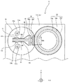
図1は、本実施形態に係る定着装置9の概略構成図である。
定着装置9は、回転駆動する接触部材である加圧ローラ30と、略円筒状の定着部材である定着ベルト38とが設けられている。円筒状の定着ベルト38の内側には、ニップ形成部材を構成する加圧パッド60及びステー部材61と、複数の発熱体としての第一ハロゲンヒータ50a及び第二ハロゲンヒータ50bと、が設けられている。
FIG. 1 is a schematic configuration diagram of a
The fixing
図1に示すように、第一ハロゲンヒータ50a及び第二ハロゲンヒータ50bは、ステー部材61を挟んで上下方向の両側にそれぞれ配置されている。
さらに、二つのハロゲンヒータ50とステー部材61との間には、ハロゲンヒータ50から放射された輻射熱を定着ベルト38の内周面に向けて反射するリフレクタ40が配置されている。
また、定着装置9の長手方向(図1中の紙面に直交する方向)の両端部には、複写機500の構造体の一部であって、上述した定着装置9の構成部材を支持する支持側板70を有する。
As shown in FIG. 1, the
Further, between the two halogen heaters 50 and the
At both ends of the fixing
定着ベルト38は、柔軟に変形可能な円筒状の加熱回転体であり、円筒形状の外形が30[mm]で、厚みが10〜70[μm]のニッケル(Ni)製の基体と、この基体表面に被覆された弾性層とを有する。弾性層は、シリコーンゴムで形成されており厚みは50〜150[μm]である。
定着ベルト38の最表層には、耐久性を高めて離型性を確保するために、フッ素系樹脂からなる厚みが5〜50[μm]の離型層が形成されている。フッ素系樹脂としては、PFA(テトラフルオロエチレン・パーフルオロアルキルビニルエーテル共重合)やPTFE(ポリテトラフルオロエチレン)を挙げることができるが、これに限るものではない。
また、定着ベルト基体はニッケルに限らず、SUS(ステンレス鋼)などの金属基体もしくはPI(ポリイミド)等の耐熱性樹脂であってもよい。
The fixing
On the outermost layer of the fixing
The fixing belt base is not limited to nickel, but may be a metal base such as SUS (stainless steel) or a heat-resistant resin such as PI (polyimide).
加圧ローラ30は外径が30[mm]であり、中空の鉄製芯金30aと、この鉄製芯金30aの表面に形成された弾性層30bと離型層30cと、で形成されている。
弾性層30bはシリコーンゴムで形成されており厚みは5[mm]である。 弾性層30bの表面には、離型性を高めるために厚みが40[μm]程度のフッ素樹脂からなる離型層30cを形成するのが望ましい。加圧ローラ30は付勢手段により定着ベルト38に向けて付勢され、加圧ローラ30と定着ベルト38とが圧接される構成となっている。
The
The
加圧パッド60は、LCP(液晶ポリマー)等の耐熱性が高い樹脂材料からなる樹脂部60aと、この樹脂部60aに覆い被さって定着ベルト38内面と摺接し、定着ベルト38の長手方向の温度分布を均一化する銅製の均熱部60bと、で形成される。加圧パッド60が定着ベルト38を挟んで加圧ローラ30と圧接して定着ニップSNを形成している。
加圧パッド60はステー部材61によって支持されている。ステー部材61の長手方向の両端部は支持側板70によって支持され、加圧ローラ30の加圧パッド60に対する押し圧力を、加圧パッド60を内側から補強する補強部材であるステー部材61が受け止め、定着ニップSNを形成している。
The
The
二本のハロゲンヒータ50(a,b)はステー部材61を挟んで上下方向両側に配置され、支持側板70よりも長手方向の外側に位置するヒータフォルダによって長手方向両端部を支持されている。
第一ハロゲンヒータ50aは、小サイズの転写紙Sの幅に対応する幅狭の領域に第一発光部フィラメント51aが長手方向に配されている。第二ハロゲンヒータ50bは、大サイズの転写紙Sの幅に対応する幅広領域における小サイズの転写紙Sの幅よりも外側の領域に第二発光部フィラメント51bが長手方向に配されている。
The two halogen heaters 50 (a, b) are arranged on both sides in the vertical direction with the
In the
リフレクタ40は、ハロゲンヒータ50とステー部材61とが対向する位置に配置され、その長手方向両端部が支持側板70によって支持されている。リフレクタ40は、アルミ製の基体とこの基体表面に塗布された銀ペーストで形成され、ハロゲンヒータ50の輻射熱を反射面40fで定着ベルト38へ向けて反射する。リフレクタ40は、ステー部材61及び加圧パッド60と、ハロゲンヒータ50との間を遮るように、板状の部材を複数回折り曲げた形状となっている。このように折り曲げた形状とすることで、リフレクタ40は、反射面40fにおけるハロゲンヒータ50と対向する位置の表面の角度が変化している構成となっている。
The
また、ハロゲンヒータ50の中心からリフレクタ40の反射面40fに降ろした垂線と反射面40fとが交わる位置には、この位置を頂点41とする山型形状43が形成されている。このような山型形状43を備えることにより、ハロゲンヒータ50から照射された輻射熱のうち、上記垂線に沿って反射面40fに入射する輻射熱は、山型形状43の斜面に入射する。このとき、輻射熱の入射方向と山型形状43の斜面とは直角ではないため、輻射熱は入射した方向とは異なる方向に向けて反射する。このため、反射面40fに入射した輻射熱をハロゲンヒータ50の通過を避けて定着ベルト38へ向けて反射でき、輻射熱がハロゲンヒータ50自体を加熱することを防止できる。
Further, at a position where a perpendicular line dropped from the center of the halogen heater 50 to the
ここで、従来の定着装置について説明する。
複写機、プリンタ、ファクシミリ等の画像形成装置では、像担持体上に画像情報に基づいてトナー像を形成し、このトナー像を紙やOHPシート等の記録材上に転写し、トナー像を担持した記録材を定着装置に通して熱と圧力によりトナー像を記録材上に固定する。
定着装置には、省エネルギーの観点や画像形成装置の使用時にユーザーを待たせないようにする等の観点から、加熱部材を瞬時に加熱することによって待ち時間(ウォームアップタイム)を短縮することが望まれている。そして、省エネルギーや待ち時間の短縮を実現する定着装置としては、ハロゲンヒータによって薄いベルトおよびフィルム、または薄肉ローラを直接加熱する技術が提案されている。
Here, a conventional fixing device will be described.
2. Description of the Related Art In an image forming apparatus such as a copying machine, a printer, and a facsimile, a toner image is formed on an image carrier based on image information, and the toner image is transferred onto a recording material such as paper or an OHP sheet to carry the toner image. The recording material thus passed is passed through a fixing device to fix a toner image on the recording material by heat and pressure.
From the viewpoint of energy saving and keeping the user from waiting when using the image forming apparatus, the fixing device is expected to reduce the waiting time (warm-up time) by instantly heating the heating member. It is rare. As a fixing device that achieves energy saving and shortens the waiting time, a technique has been proposed in which a thin belt and a film or a thin roller are directly heated by a halogen heater.
特許文献1に記載の定着装置は、加熱ローラよりも熱容量の低いエンドレス状の定着ベルトを用い、定着ベルトの内側に加圧パッドとその補強部材を備える構成としたことで、より省エネルギーかつ待ち時間を短縮した定着装置を実現している。また、画像形成装置の小型化に伴って定着ベルトが小径化され、定着ベルトの内側の補強部材や反射部材と発熱体との間の距離が短くなっている。反射部材と発熱体との距離が近いと、反射部材によって反射した輻射熱が発熱体を通過する量が増加し、定着ベルトに対する加熱効率は減少してしまう。
The fixing device described in
発熱体と反射部材との必要な距離を確保するために反射部材の厚みを薄くすると、薄くした結果剛性が低くなり反射部材が長手方向に対し自重で撓むおそれがある。このような撓みの発生を防止する構成として、反射部材を補強部材に完全に固定又は一体として形成する構成が考えられる。 When the thickness of the reflecting member is reduced in order to secure a necessary distance between the heating element and the reflecting member, rigidity is reduced as a result of the thinning, and the reflecting member may be bent by its own weight in the longitudinal direction. As a configuration for preventing the occurrence of such bending, a configuration in which the reflection member is completely fixed to or integrally formed with the reinforcing member can be considered.
また、定着ベルトの内側に存在する複数のハロゲンヒータ同士の間に補強部材を配置することで、ハロゲンヒータ同士の加熱を防止できる。さらに、補強部材に取り付けた反射部材の反射面におけるハロゲンヒータと対向する位置、すなわち、ハロゲンヒータの中心から反射面に下ろした垂線が反射面と交わる位置を山型形状とする。これにより、ハロゲンヒータから反射部材への略垂直な入射を無くし、輻射熱が反射部材で反射されてハロゲンヒータ自身を加熱してしまうことを防止し、反射した輻射熱で定着ベルトを加熱できる。
このような定着装置では、上記垂線が反射面と交わる位置と、山型形状の頂点の位置とを精度良く合わせることが、反射部材への略垂直な入射を無くし、輻射熱がハロゲンヒータ自身を加熱してしまうことを防止する上で重要である。
Further, by arranging the reinforcing member between the plurality of halogen heaters existing inside the fixing belt, the heating of the halogen heaters can be prevented. Further, a position facing the halogen heater on the reflection surface of the reflection member attached to the reinforcing member, that is, a position where a perpendicular drawn from the center of the halogen heater to the reflection surface intersects the reflection surface has a mountain shape. This eliminates substantially perpendicular incidence from the halogen heater to the reflecting member, prevents radiant heat from being reflected by the reflecting member and heating the halogen heater itself, and heats the fixing belt with the reflected radiant heat.
In such a fixing device, it is necessary to precisely match the position at which the perpendicular intersects the reflecting surface with the position of the peak of the mountain shape, so that substantially perpendicular incidence on the reflecting member is eliminated, and the radiant heat heats the halogen heater itself. It is important to prevent that.
上述のような、熱容量の低いエンドレス状の定着ベルトと定着ベルトの内側の加圧パッドおよび補強部材を備える構成では、定着ベルトの外側に存在する加圧ローラと加圧パッドとが圧接することで定着ニップを形成する。このとき、加圧パッドおよび補強部材の長手方向全域に圧接方向の加圧力がかかり長手方向で撓みが生じる。そして補強部材に反射部材を取り付ける構成では、加圧力による補強部材の撓みに反射部材が追従し、反射部材山型形状の頂点とハロゲンヒータの中心との位置がずれ、定着ベルトの加熱効率向上効果が得られなくなってしまう。 In the configuration including the endless fixing belt having a low heat capacity, the pressure pad inside the fixing belt, and the reinforcing member as described above, the pressure roller and the pressure pad existing outside the fixing belt come into pressure contact with each other. Form a fixing nip. At this time, a pressing force in the pressing direction is applied to the entire region in the longitudinal direction of the pressing pad and the reinforcing member, and bending occurs in the longitudinal direction. In the configuration in which the reflection member is attached to the reinforcement member, the reflection member follows the bending of the reinforcement member due to the pressing force, and the position of the peak of the reflection member mountain shape and the center of the halogen heater are shifted, thereby improving the heating efficiency of the fixing belt. Will not be obtained.
この撓みは補強部材を大型にして剛性を高めることにより防止することが考えられる。しかし、補強部材は定着ベルトの内側に収める必要があるため、大型化は困難である。そのため、多少の撓みを許容し、撓みを考慮に入れて加圧パッドおよび補強部材の形状を決めることが一般的である。 It is conceivable that this bending can be prevented by increasing the size of the reinforcing member and increasing the rigidity. However, since the reinforcing member needs to be accommodated inside the fixing belt, it is difficult to increase the size. For this reason, it is common to allow some bending and determine the shapes of the pressure pad and the reinforcing member in consideration of the bending.
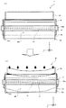
図11は、リフレクタ40を支持側板70ではなく、ステー部材61に固定した点で上述した実施形態の定着装置9と異なる比較例の定着装置9の斜視説明図である。図11は、定着ベルト38を取り外した状態であり、便宜的に定着ベルト38の軌道のみを破線で示している。
図12は、比較例の定着装置9を上方から見たものを模式的に示した上面模式図である。図12(a)は、加圧ローラ30を定着ベルト38に向けて付勢していない非圧接時を示し、図12(b)は、加圧ローラ30を定着ベルト38に向けて付勢している圧接時を示す。
FIG. 11 is a perspective explanatory view of a
FIG. 12 is a schematic top view schematically showing the fixing
比較例は、ステー部材61によるリフレクタ40の支持構成であり、リフレクタ40は、ステー部材61の長手方向両端に固定ネジ42で固定されている。そして、図12(a)に示すように、非圧接時には、装置横方向(図中のX軸に平行な方向)について、リフレクタ40の山型形状43の頂点41の位置と、第一ハロゲンヒータ50aの中心の位置とは一致している。
In the comparative example, the
圧接時には、加圧ローラ30が定着ベルト38に向けて付勢され、定着ベルト38及び加圧パッド60を介してステー部材61に加圧力が作用する。そして、ステー部材61に加圧力が作用すると、図12(b)に示すように、ステー部材61には、長手方向の中央部が加圧ローラ30から離れるように撓んだ変形が生じる。
At the time of pressure contact, the
このとき、リフレクタ40は、ステー部材61に追従して変形し、上述した山型形状43の頂点41は長手方向の中央部が加圧ローラ30から離れるように変位する。このため、装置横方向について、リフレクタ40の山型形状43の頂点41の位置と、第一ハロゲンヒータ50aの中心の位置とが大幅にずれる箇所が生じる。その結果、入射した輻射熱を第一ハロゲンヒータ50aの通過を避けて定着ベルト38へ反射できなくなり、ベルト加熱効率は下がってしまう。
上述した比較例の説明では、第一ハロゲンヒータ50aについて説明したが、ステー部材61を挟んで反対側に位置する第二ハロゲンヒータ50bについても同様の問題が生じる。
At this time, the
In the above description of the comparative example, the
図3は、実施形態の定着装置9の斜視説明図である。図3は、定着ベルト38を取り外した状態である。
図4は、実施形態の定着装置9を上方から見たものを模式的に示した上面模式図である。図4(a)は、加圧ローラ30を定着ベルト38に向けて付勢していない非圧接時を示し、図4(b)は、加圧ローラ30を定着ベルト38に向けて付勢している圧接時を示す。
FIG. 3 is an explanatory perspective view of the fixing
FIG. 4 is a schematic top view schematically showing the fixing
実施形態の定着装置9は、支持側板70によるリフレクタ40の支持構成である。リフレクタ40の長手方向両端部の5〜8[mm]を二つの支持側板70(奥側支持側板70a,手前側支持側板70b)に挿入することで、リフレクタ40が支持側板70に固定されている。そして、図4(a)に示すように、非圧接時には、装置横方向について、リフレクタ40の山型形状43の頂点41の位置と、第一ハロゲンヒータ50aの中心の位置とは一致している。
The fixing
また、ステー部材61も支持側板70に固定されおり、支持側板70におけるリフレクタ40の挿入部から1[mm]下の位置に、ステー部材61の長手方向両端部の5〜8[mm]を挿入することで固定されている。
The
圧接時には、加圧ローラ30が定着ベルト38に向けて付勢され、定着ベルト38及び加圧パッド60を介してステー部材61に加圧力が作用する。そして、ステー部材61に加圧力が作用すると、図4(b)に示すように、ステー部材61には、長手方向の中央部が加圧ローラ30から離れるように撓んだ変形が生じる。
At the time of pressure contact, the
実施形態の定着装置9では、リフレクタ40は、ステー部材61に固定されておらず、二つの支持側板70(a,b)に支持されているため加圧パッド60及びステー部材61の変形に追従しない。このため、非圧接時でも、装置横方向について、リフレクタ40の山型形状43の頂点41の位置と、第一ハロゲンヒータ50aの中心の位置との位置ずれが生じない。すなわち、第一ハロゲンヒータ50aの中心位置と山型形状43の頂点41の位置との位置精度を保つことができる。
In the
その結果、リフレクタ40への略垂直な輻射熱の入射を無くし、リフレクタ40に入射した輻射熱を第一ハロゲンヒータ50aの通過を避けて定着ベルト38へ反射できる状態を維持でき、ベルト加熱効率を維持することができる。
また、定着装置9におけるベルト加熱効率を維持することにより、複写機500全体での消費電力を低減でき、省エネルギー化を図ることができる。
As a result, it is possible to eliminate the incidence of substantially perpendicular radiant heat to the
Further, by maintaining the belt heating efficiency in the
また、ステー部材61も支持側板70に固定することで、部品点数の増加を抑制しつつ、ステー部材61が撓むことによってリフレクタ40が変形することを防止できる。
図1に示すように、複数のハロゲンヒータ50の間にステー部材61及びリフレクタ40を配置することで、をハロゲンヒータ50同士の加熱を防止できる。
Also, by fixing the
By arranging the
〔変形例〕
次に、本実施形態に係る定着装置9の変形例について説明する。
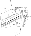
図5は、変形例の定着装置9の斜視説明図、図6は、変形例の定着装置9の側面図、図7は、変形例の定着装置9を図5とは異なる角度から拡大して見た拡大斜視図である。
図5乃至図7は、定着ベルト38、第二ハロゲンヒータ50b、及び、第二ハロゲンヒータ50bと対向するリフレクタ40を取り外した状態である。
(Modification)
Next, a modified example of the fixing
FIG. 5 is a perspective explanatory view of the fixing
5 to 7 show a state in which the fixing
図5に示すように、変形例の定着装置9は、支持側板70によって、ステー部材61、リフレクタ40及びハロゲンヒータ50を同時に支持する構成である。
図5に示すように、支持側板70にはハロゲンヒータ50を挿入する五角形状のヒータ支持開口部71が形成されている。そして、図6に示すように、ヒータ支持開口部71の五角形状における下方に突き出た山型形状を形成する二つの平面に載せたハロゲンヒータ50をヒータ固定部材73によって上方から抑える状態とする。これにより、ハロゲンヒータ50は、二つの平面との接触部と、ヒータ固定部材73との接触部との計三点と接触し固定されている。
As shown in FIG. 5, the fixing
As shown in FIG. 5, a pentagonal heater support opening 71 into which the halogen heater 50 is inserted is formed in the
そして、ヒータ支持開口部71の下方に突き出た山型形状の頂点と、リフレクタ40を挿入するために支持側板70に設けた開口部におけるリフレクタ40の山型形状43の頂点41に対応する部分との装置横方向についての位置を一致させる。これにより、ハロゲンヒータ50の中心とリフレクタ40の山型形状43の頂点41との位置決めを精度良く行うことが出来る。
Then, a vertex of the mountain shape protruding below the
次に、図7を用いて、リフレクタ40とリフレクタ40に張力を付加する板バネ72との構成を説明する。
板バネ72は、一方の端部が支持側板70に圧入して固定され、他方の端部がリフレクタ40に挿入され略直角な「L」の字状に曲がっている。板バネ72は自然状態では図7中の「72a」で示すように、直角よりも長手方向外側に広がるような形状をしており、略直角に曲げる状態で他方の端部をリフレクタ40に圧入する。これにより、板バネ72が自然状態に戻ろうとする力がリフレクタ40に作用する。図5〜7では、手前側支持側板70bに板バネ72を挿入する状態を示しているが、奥側支持側板70aにも同様に板バネ72を略直角に曲げた状態で挿入する。これにより、二つの板バネ72が自然状態に戻ろうとする力がリフレクタ40を長手方向に引っ張るように作用し、リフレクタ40の自重により長手方向について撓みが生じることを防止している。
Next, the configuration of the
One end of the
図8及び図9は、リフレクタ40の反射面40fにおいて、輻射熱が入射してきた方向とは異なる方向に向けて輻射熱を反射する形状として、山型形状43以外の形状を備える定着装置9の概略構成図である。
リフレクタ40におけるハロゲンヒータ50と対向する部分の形状が異なる点以外は共通するため、相違点についてのみ説明する。
FIGS. 8 and 9 show a schematic configuration of the fixing
The
図8に示す定着装置9は、リフレクタ40におけるハロゲンヒータ50と対向する部分にハロゲンヒータ50に向かって突起する円弧形状44を備える。このような円弧形状44の外周面において、輻射熱の入射方向と直角となる部分は非常に限られた範囲となり、他の範囲に入射した輻射熱は入射した方向とは異なる方向に向けて反射される。このため、上述した実施形態の定着装置9と同様に、反射面40fに入射した輻射熱をハロゲンヒータ50の通過を避けて定着ベルト38へ向けて反射できる。
The fixing
図9に示す定着装置9は、リフレクタ40におけるハロゲンヒータ50と対向する部分にハロゲンヒータ50に対して凹んだ谷型形状45を備える。このような谷型形状45を形成する斜面と輻射熱の入射方向とは直角ではないため、輻射熱は入射した方向とは異なる方向に向けて反射する。このため、上述した実施形態の定着装置9と同様に、反射面40fに入射した輻射熱をハロゲンヒータ50の通過を避けて定着ベルト38へ向けて反射できる。なお、図9に示す谷型形状45を備える構成の場合、谷型形状45の二つの斜面が互いに直角であると、輻射熱は入射した方向に向けて反射するおそれがあるため、二つの斜面が直角とならない配置とすることが望ましい。
The fixing
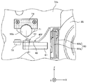
図10は、リフレクタ40の反射面40fにおいて、輻射熱が入射してきた方向とは異なる方向に向けて輻射熱を反射する形状として、平行で且つ段違いの二つの平面部と、その二つの平面部を繋ぐ傾斜平面部とを有する定着装置9の概略構成図である。
リフレクタ40の形状が異なる点以外は上述した図1に示す定着装置9と共通するため、相違点についてのみ説明する。
FIG. 10 shows two parallel plane-shaped portions having different levels, and a shape that reflects the radiant heat in a direction different from the direction in which the radiant heat is incident on the reflecting
Except for the point that the shape of the
図10に示す定着装置9は、加圧パッド60に対して起立して支持するステー部材61の起立部を覆うように二つのリフレクタ40を配置する。リフレクタ40の当該箇所は、図10に示すように平行で且つ段違いの二つの平面部である第一反射平面部46A及び第三反射平面部46Cと、第一反射平面部46Aと第三反射平面部46Cとを繋ぐ傾斜平面部である第二反射平面部46Bとで形成されている。
In the
二つのハロゲンヒータ50(50a,50b)は、それぞれ第二反射平面部46Bと対向する箇所に位置しており、第二反射平面部46Bに入射する輻射熱の入射角度は斜面に対して直角ではない。このため、第二反射平面部46Bでは、輻射熱が入射してきた方向とは異なる方向に向けて輻射熱が反射され、第二反射平面部46Bで反射した輻射熱がハロゲンヒータ50に向かうことを抑制できる。よって、図10中の矢印「H」で示すように、第二反射平面部46Bに入射したハロゲンヒータ50からの輻射熱は、ハロゲンヒータ50には戻らず、加圧パッド60とは反対側の定着ベルト38に向かって反射される。したがって、輻射熱がハロゲンヒータ50自体(ハロゲンヒータ50を構成するガラス管等)を加熱することを防止することにより、定着ベルト38を効率良く加熱することができる。
The two halogen heaters 50 (50a, 50b) are respectively located at locations facing the second reflection plane 46B, and the incident angle of radiant heat incident on the second reflection plane 46B is not perpendicular to the slope. . For this reason, the radiant heat is reflected in a direction different from the direction in which the radiant heat is incident on the second reflecting flat portion 46B, and the radiant heat reflected on the second reflecting flat portion 46B can be suppressed from going to the halogen heater 50. Therefore, as indicated by an arrow “H” in FIG. 10, the radiant heat from the halogen heater 50 incident on the second reflection plane portion 46 </ b> B does not return to the halogen heater 50, and the fixing heat on the side opposite to the
本実施形態の複写機500は、用紙を下方から上方に搬送する縦搬送方式の画像形成装置である。このため、定着装置9は、定着ベルト38と加圧ローラ30とが水平方向に配置した構成となっている。画像形成装置としては、用紙を水平方向に搬送する横搬送方式のものでもよく、この場合、定着装置としては、定着ベルトと加圧ローラとを上下方向に配置し、上述した実施形態の定着装置9を90[°]回転させた構成のものを用いることができる。
The copying
以上に説明したものは一例であり、次の態様毎に特有の効果を奏する。 What has been described above is merely an example, and each embodiment has a specific effect.
(態様A)
回転可能に設けられた無端状の定着ベルト38等の回転体と、回転体の外周面と接触する加圧ローラ30等の接触部材と、回転体の内側に配置され回転体を介して接触部材と当接し定着ニップSN等のニップ部を形成する加圧パッド60及びステー部材61等のニップ形成部材と、回転体の内側に配置されたハロゲンヒータ50等の発熱体と、回転体の内側に配置され、発熱体からニップ形成部材に向けて放射される輻射熱を反射面40f等の反射面で反射するリフレクタ40等の反射部材とを備え、ニップ形成部材は、回転体の内周面に摺擦する加圧パッド60等の摺擦部と、摺擦部から回転体の内側に向けて起立するステー部材61等の補強部と、を有し、発熱体は補強部の起立する部分の側面と対向するように配置され、反射部材は、反射面における発熱体と対向する位置に、発熱体から放射される輻射熱を発熱体に向かわない方向に反射させる山型形状43等の表面の角度が変化している反射形状を有する定着装置9等の定着装置において、反射部材を、ニップ形成部材とは別体の支持側板70等の反射支持部材で支持する。
これによれば、上記実施形態について説明したように、反射部材をニップ形成部材とは別体の反射支持部材で支持することで、ニップ形成部材の補強部とは独立して反射部材を固定することが可能となる。よって、接触部材との接触圧によってニップ形成部材に回転体の内側に向かう撓みが生じても、反射部材が撓みに追従して変形しない構成を実現できる。このため、反射部材の反射形状と発熱体との位置関係が、ニップ形成部材が撓むことに起因してずれることを防止し、位置関係を維持することが可能となる。ニップ形成部材に撓みが生じても、反射部材の反射形状と発熱体との位置関係を維持することにより、反射部材の反射形状によって定着ベルトを効率よく加熱する作用を維持することができる。
(Aspect A)
A rotatable rotatable member such as an
According to this, as described in the above embodiment, by supporting the reflection member with the reflection support member separate from the nip formation member, the reflection member is fixed independently of the reinforcing portion of the nip formation member. It becomes possible. Therefore, even when the nip forming member is bent toward the inside of the rotating body due to the contact pressure with the contact member, a configuration in which the reflecting member follows the bending and does not deform can be realized. For this reason, it is possible to prevent the positional relationship between the reflecting shape of the reflecting member and the heating element from being shifted due to the bending of the nip forming member, and to maintain the positional relationship. Even if the nip forming member is bent, by maintaining the positional relationship between the reflection shape of the reflection member and the heating element, it is possible to maintain the function of efficiently heating the fixing belt by the reflection shape of the reflection member.
(態様B)
態様Aにおいて、反射形状は、反射面40f等の反射面からハロゲンヒータ50等の発熱体に向かって突起した山型形状43または円弧形状44等の凸部であり、支持側板70等の反射支持部材は、反射部材が発熱体とステー部材61等の補強部との間に位置し、反射面の凸部の突起方向の延長線上に発熱体の中心点が位置するように、反射部材を固定する。
これによれば、上記実施形態について説明したように、反射面に入射した輻射熱を発熱体の通過を避けて定着ベルト38等の回転体へ向けて反射でき、輻射熱が発熱体自体を加熱することを防止できる。
(Aspect B)
In the embodiment A, the reflection shape is a convex portion such as a
According to this, as described in the above embodiment, the radiant heat incident on the reflecting surface can be reflected toward the rotating body such as the fixing
(態様C)
態様AまたはBの何れかの態様において、反射形状は、反射面40f等の反射面からハロゲンヒータ50等の発熱体に向かって突起した山型形状43等の山型形状である。
これによれば、上記実施形態について説明したように、反射面における発熱体と対向する位置に入射する輻射熱は山型形状の斜面に入射し、入射した方向とは異なる方向に向けて反射する。これにより、反射した輻射熱が発熱体を通過することを避けて定着ベルト38等の回転体に入射する構成を実現することが可能となる。
(Aspect C)
In any one of Embodiments A and B, the reflection shape is a mountain shape such as a
According to this, as described in the above-described embodiment, the radiant heat incident on the reflection surface at a position facing the heating element is incident on the mountain-shaped slope, and is reflected in a direction different from the incident direction. Thereby, it is possible to realize a configuration in which the reflected radiant heat is incident on a rotating body such as the fixing
(態様D)
態様AまたはBの何れかの態様において、反射形状は、反射面40f等の反射面からハロゲンヒータ50等の発熱体に向かって突起した円弧形状44等の円弧形状である。
これによれば、上記実施形態について説明したように、反射面における発熱体と対向する位置の近傍に入射する輻射熱は円弧形状の表面に入射し、入射した方向とは異なる方向に向けて反射する。これにより、反射した輻射熱が発熱体を通過することを避けて定着ベルト38等の回転体に入射する構成を実現することが可能となる。
(Aspect D)
In any one of Embodiments A and B, the reflection shape is an arc shape such as an
According to this, as described in the above embodiment, radiant heat incident near the position facing the heating element on the reflecting surface is incident on the arc-shaped surface and reflected in a direction different from the incident direction. . Thereby, it is possible to realize a configuration in which the reflected radiant heat is incident on a rotating body such as the fixing
(態様E)
態様AまたはBの何れかの態様において、リフレクタ40等の反射部材は、ステー部材61等の補強部材の起立する部分と平行で且つ段違いの二つの平面部(第一反射平面部46A及び第三反射平面部46C等)を有し、反射形状は、二つの平面部を繋ぐ第二反射平面部46B等の傾斜平面部である。
これによれば、上記実施形態について説明したように、反射面における発熱体と対向する位置の近傍に入射する輻射熱は、入射方向に対して直角な面ではない傾斜平面部の表面に入射し、入射した方向とは異なる方向に向けて反射する。これにより、反射した輻射熱が発熱体を通過することを避けて定着ベルト38等の回転体に入射する構成を実現することが可能となる。また、反射部材と発熱体との位置関係がずれても、輻射熱が反射面に入射する位置の表面は、輻射熱の入射方向に対して直角な面ではない傾斜平面部の表面となる。このため、反射部材と発熱体との位置関係がずれても、反射部材の反射面で反射された輻射熱が加熱源に戻って加熱源自体の加熱に輻射熱が用いられるのを抑えられ、定着ベルト38等の回転体を効率良く加熱することができる。
(Aspect E)
In any one of Embodiments A and B, the reflecting member such as the
According to this, as described in the above embodiment, radiant heat incident near the position facing the heating element on the reflection surface is incident on the surface of the inclined plane portion that is not a surface perpendicular to the incident direction, The light is reflected in a direction different from the incident direction. Thereby, it is possible to realize a configuration in which the reflected radiant heat is incident on a rotating body such as the fixing
(態様F)
態様A乃至Eの何れかの態様において、支持側板70等の反射支持部材は、ステー部材61等の補強部を支持する。
これによれば、上記実施形態について説明したように、反射支持部材が補強部の支持部材を兼ねることで、部品点数の増加を抑制しつつ、補強部が撓むことによってリフレクタ40等の反射部材が変形することを防止できる。
(Aspect F)
In any one of the modes A to E, the reflection support member such as the
According to this, as described in the above-described embodiment, the reflection support member also serves as the support member of the reinforcing portion, thereby suppressing an increase in the number of components, and the bending of the reinforcement portion, thereby causing the reflection member such as the
(態様G)
態様A乃至Fの何れかの態様において、支持側板70等の反射支持部材は、ハロゲンヒータ50等の発熱体を支持する。
これによれば、上記変形例について説明したように、反射支持部材が発熱体の支持部材を兼ねることで、発熱体の中心と、リフレクタ40等の反射部材の山型形状43等の反射形状との位置決めを精度良く行うことが出来る。
(Aspect G)
In any one of the modes A to F, the reflection support member such as the
According to this, as described in the above modification, the reflection support member also serves as the support member of the heating element, so that the center of the heating element and the reflection shape such as the
(態様H)
態様A乃至Gの何れかの態様において、支持側板70等の反射支持部材は、リフレクタ40等の反射部材をステー部材61等の補強部から1[mm]等の所定距離だけ離れた位置で固定する。
これによれば、上記実施形態について説明したように、補強部が撓むことによって反射部材が変形することを防止できる。
(Aspect H)
In any one of Embodiments A to G, the reflection support member such as the
According to this, as described in the above embodiment, it is possible to prevent the deformation of the reflection member due to the bending of the reinforcing portion.
(態様I)
態様A乃至Hの何れかの態様において、リフレクタ40等の反射部材に対して、定着ベルト38等の回転体の回転軸方向(長手方向等)の中心から外側へ向けた張力を作用させる板バネ72等の反射部材引っ張り手段を備える。
これによれば、上記変形例について説明したように、反射部材がその自重により撓みが生じることを防止している。
(Aspect I)
In any one of Aspects A to H, a leaf spring for applying a tension from a center of a rotating body such as a fixing
According to this, as described in the above-described modification, the reflection member is prevented from bending due to its own weight.
(態様J)
トナーを用いて記録媒体上にトナー像を形成する画像形成部200等のトナー像形成手段と、加熱して転写紙S等の記録媒体上にトナー像を定着させる定着手段とを備える複写機500等の画像形成装置において、定着手段として、態様A乃至Iの何れかの態様に係る定着装置9等の定着装置を用いる。
これによれば、上記実施形態について説明したように、定着装置におけるベルト加熱効率を維持することにより、画像形成装置全体での省エネルギー化を図ることができる。
(Aspect J)
A
According to this, as described in the above embodiment, by maintaining the belt heating efficiency in the fixing device, it is possible to achieve energy saving in the entire image forming apparatus.
1 作像装置
2 帯電装置
3 感光体
5 現像装置
6 一次転写ローラ
7 クリーニング装置
8 排紙トレイ
9 定着装置
10 給紙カセット
11 給紙ローラ
12 レジストローラ対
15 現像ローラ
16 中間転写ベルト
18 排紙ローラ
20 トナーボトル
26 二次転写ローラ
30 加圧ローラ
30a 鉄製芯金
30b 弾性層
30c 離型層
32 第一走行体
31 コンタクトガラス
32a 原稿照明用光源
32b 第一ミラー
33 レンズ
34 CCD
35 第二走行体
35a 第二ミラー
35b 第三ミラー
38 定着ベルト
40 リフレクタ
40f 反射面
41 頂点
42 固定ネジ
43 山型形状
44 円弧形状
45 谷型形状
46A 第一反射平面部
46B 第二反射平面部
46C 第三反射平面部
50 ハロゲンヒータ
50a 第一ハロゲンヒータ
50b 第二ハロゲンヒータ
51a 第一発光部フィラメント
51b 第二発光部フィラメント
60 加圧パッド
60a 樹脂部
60b 均熱部
61 ステー部材
70 支持側板
70a 奥側支持側板
70b 手前側支持側板
71 ヒータ支持開口部
72 板バネ
73 ヒータ固定部材
100 書込ユニット
200 画像形成部
300 スキャナ部
400 給紙部
500 複写機
S 転写紙
SN 定着ニップ
REFERENCE SIGNS
35
Claims (11)
前記回転体の外周面と接触する接触部材と、
前記回転体の内側に配置され前記回転体を介して前記接触部材と当接しニップ部を形成するニップ形成部材と、
前記回転体の内側に配置された発熱体と、
前記回転体の内側に配置され、前記発熱体から前記ニップ形成部材に向けて放射される輻射熱を反射面で反射する反射部材とを備え、
前記ニップ形成部材は、前記回転体の内周面に摺擦する摺擦部と、前記摺擦部から前記回転体の内側に向けて起立する補強部と、を有し、
前記発熱体は前記補強部の起立する部分の側面と対向するように配置され、
前記反射部材は、前記反射面における前記発熱体と対向する位置の表面の角度が変化している反射形状を有する定着装置において、
前記反射部材を、前記ニップ形成部材とは別体の反射支持部材で支持し、
前記反射形状は、前記反射面から前記発熱体に向かって突起した山型形状であることを特徴とする定着装置。 An endless rotating body provided rotatably,
A contact member that contacts an outer peripheral surface of the rotating body,
A nip forming member that is disposed inside the rotating body and contacts the contact member via the rotating body to form a nip portion;
A heating element disposed inside the rotating body;
A reflecting member that is disposed inside the rotating body and reflects, on a reflecting surface, radiant heat radiated from the heating element toward the nip forming member,
The nip forming member has a rubbing portion that rubs against the inner peripheral surface of the rotating body, and a reinforcing portion that stands up from the rubbing portion toward the inside of the rotating body,
The heating element is disposed so as to face a side surface of a portion where the reinforcing portion stands,
In the fixing device, the reflection member has a reflection shape in which an angle of a surface of the reflection surface at a position facing the heating element is changed.
The reflective member is supported by a reflective support member separate from the nip forming member ,
The fixing device according to claim 1, wherein the reflection shape is a chevron shape protruding from the reflection surface toward the heating element .
前記回転体の外周面と接触する接触部材と、
前記回転体の内側に配置され前記回転体を介して前記接触部材と当接しニップ部を形成するニップ形成部材と、
前記回転体の内側に配置された発熱体と、
前記回転体の内側に配置され、前記発熱体から前記ニップ形成部材に向けて放射される輻射熱を反射面で反射する反射部材とを備え、
前記ニップ形成部材は、前記回転体の内周面に摺擦する摺擦部と、前記摺擦部から前記回転体の内側に向けて起立する補強部と、を有し、
前記発熱体は前記補強部の起立する部分の側面と対向するように配置され、
前記反射部材は、前記反射面における前記発熱体と対向する位置の表面の角度が変化している反射形状を有する定着装置において、
前記反射部材を、前記ニップ形成部材とは別体の反射支持部材で支持し、
前記反射形状は、前記反射面から前記発熱体に向かって突起した円弧形状であることを特徴とする定着装置。 An endless rotating body provided rotatably,
A contact member that contacts an outer peripheral surface of the rotating body;
A nip forming member that is disposed inside the rotating body and contacts the contact member via the rotating body to form a nip portion;
A heating element disposed inside the rotating body;
A reflecting member that is disposed inside the rotating body and reflects, on a reflecting surface, radiant heat radiated from the heating element toward the nip forming member,
The nip forming member has a rubbing portion that rubs against the inner peripheral surface of the rotating body, and a reinforcing portion that stands up from the rubbing portion toward the inside of the rotating body,
The heating element is disposed so as to face a side surface of a portion where the reinforcing portion stands,
In the fixing device, the reflection member has a reflection shape in which an angle of a surface of the reflection surface at a position facing the heating element is changed.
The reflective member is supported by a reflective support member separate from the nip forming member,
The fixing device according to claim 1, wherein the reflection shape is an arc shape protruding from the reflection surface toward the heating element.
前記回転体の外周面と接触する接触部材と、
前記回転体の内側に配置され前記回転体を介して前記接触部材と当接しニップ部を形成するニップ形成部材と、
前記回転体の内側に配置された発熱体と、
前記回転体の内側に配置され、前記発熱体から前記ニップ形成部材に向けて放射される輻射熱を反射面で反射する反射部材とを備え、
前記ニップ形成部材は、前記回転体の内周面に摺擦する摺擦部と、前記摺擦部から前記回転体の内側に向けて起立する補強部と、を有し、
前記発熱体は前記補強部の起立する部分の側面と対向するように配置され、
前記反射部材は、前記反射面における前記発熱体と対向する位置の表面の角度が変化している反射形状を有する定着装置において、
前記反射部材を、前記ニップ形成部材とは別体の反射支持部材で支持し、
前記反射部材は、前記補強部の起立する部分と平行で且つ段違いの二つの平面部を有し、
前記反射形状は、前記二つの平面部を繋ぐ傾斜平面部であることを特徴とする定着装置。 An endless rotating body provided rotatably,
A contact member that contacts an outer peripheral surface of the rotating body,
A nip forming member that is disposed inside the rotating body and contacts the contact member via the rotating body to form a nip portion;
A heating element disposed inside the rotating body;
A reflecting member that is disposed inside the rotating body and reflects, on a reflecting surface, radiant heat radiated from the heating element toward the nip forming member,
The nip forming member has a rubbing portion that rubs against the inner peripheral surface of the rotating body, and a reinforcing portion that stands up from the rubbing portion toward the inside of the rotating body,
The heating element is disposed so as to face a side surface of a portion where the reinforcing portion stands,
In the fixing device, the reflection member has a reflection shape in which an angle of a surface of the reflection surface at a position facing the heating element is changed.
The reflective member is supported by a reflective support member separate from the nip forming member,
The reflection member has two plane portions parallel to and different from the upright portion of the reinforcing portion,
The fixing device according to claim 1, wherein the reflection shape is an inclined flat portion connecting the two flat portions.
前記反射形状は、前記反射面から前記発熱体に向かって突起した凸部であり、 The reflection shape is a projection protruding from the reflection surface toward the heating element,
前記反射支持部材は、前記反射部材が前記発熱体と前記補強部との間に位置し、前記反射面の前記凸部の突起方向の延長線上に前記発熱体の中心点が位置するように、前記反射部材を固定することを特徴とする定着装置。 The reflection support member is such that the reflection member is located between the heating element and the reinforcing portion, and the center point of the heating element is located on an extension of the projection direction of the projection on the reflection surface. A fixing device for fixing the reflection member.
前記回転体の外周面と接触する接触部材と、
前記回転体の内側に配置され前記回転体を介して前記接触部材と当接しニップ部を形成するニップ形成部材と、
前記回転体の内側に配置された発熱体と、
前記回転体の内側に配置され、前記発熱体から前記ニップ形成部材に向けて放射される輻射熱を反射面で反射する反射部材とを備え、
前記ニップ形成部材は、前記回転体の内周面に摺擦する摺擦部と、前記摺擦部から前記回転体の内側に向けて起立する補強部と、を有し、
前記発熱体は前記補強部の起立する部分の側面と対向するように配置され、
前記反射部材は、前記反射面における前記発熱体と対向する位置の表面の角度が変化している反射形状を有する定着装置において、
前記反射部材を、前記ニップ形成部材とは別体の反射支持部材で支持し、
前記反射形状は、前記反射面から前記発熱体に向かって突起した凸部であり、
前記反射支持部材は、前記反射部材が前記発熱体と前記補強部との間に位置し、前記反射面の前記凸部の突起方向の延長線上に前記発熱体の中心点が位置するように、前記反射部材を固定することを特徴とする定着装置。 An endless rotating body provided rotatably,
A contact member that contacts an outer peripheral surface of the rotating body;
A nip forming member that is disposed inside the rotating body and contacts the contact member via the rotating body to form a nip portion;
A heating element disposed inside the rotating body;
A reflecting member that is disposed inside the rotating body and reflects, on a reflecting surface, radiant heat radiated from the heating element toward the nip forming member,
The nip forming member has a rubbing portion that rubs against the inner peripheral surface of the rotating body, and a reinforcing portion that stands up from the rubbing portion toward the inside of the rotating body,
The heating element is disposed so as to face a side surface of a portion where the reinforcing portion stands,
In the fixing device, the reflection member has a reflection shape in which an angle of a surface of the reflection surface at a position facing the heating element is changed.
The reflective member is supported by a reflective support member separate from the nip forming member,
The reflection shape is a projection protruding from the reflection surface toward the heating element,
The reflection support member is such that the reflection member is located between the heating element and the reinforcing portion, and the center point of the heating element is located on an extension of the projection direction of the projection on the reflection surface. A fixing device for fixing the reflection member.
前記反射支持部材は、前記補強部を支持することを特徴とする定着装置。 The fixing device according to claim 1, wherein
The fixing device according to claim 1, wherein the reflection support member supports the reinforcing portion.
前記反射支持部材は、前記発熱体を支持することを特徴とする定着装置。 The fixing device according to claim 1, wherein
The fixing device according to claim 1, wherein the reflection support member supports the heating element.
前記反射支持部材は、前記反射部材を前記補強部から所定距離だけ離れた位置で固定することを特徴とする定着装置。 The fixing device according to claim 1, wherein
The fixing device, wherein the reflection support member fixes the reflection member at a position separated by a predetermined distance from the reinforcing portion.
前記反射部材に対して、前記回転体の回転軸方向の中心から外側へ向けた張力を作用させる反射部材引っ張り手段を備えることを特徴とする定着装置。 The fixing device according to claim 1, wherein
A fixing device, comprising: a reflecting member pulling unit that applies a tension to the reflecting member from a center of the rotating body in a rotation axis direction to an outer side.
前記回転体の外周面と接触する接触部材と、 A contact member that contacts an outer peripheral surface of the rotating body;
前記回転体の内側に配置され前記回転体を介して前記接触部材と当接しニップ部を形成するニップ形成部材と、 A nip forming member that is disposed inside the rotating body and contacts the contact member via the rotating body to form a nip portion;
前記回転体の内側に配置された発熱体と、 A heating element disposed inside the rotating body;
前記回転体の内側に配置され、前記発熱体から前記ニップ形成部材に向けて放射される輻射熱を反射面で反射する反射部材とを備え、 A reflecting member that is disposed inside the rotating body and reflects, on a reflecting surface, radiant heat radiated from the heating element toward the nip forming member,
前記ニップ形成部材は、前記回転体の内周面に摺擦する摺擦部と、前記摺擦部から前記回転体の内側に向けて起立する補強部と、を有し、 The nip forming member has a rubbing portion that rubs against the inner peripheral surface of the rotating body, and a reinforcing portion that stands up from the rubbing portion toward the inside of the rotating body,
前記発熱体は前記補強部の起立する部分の側面と対向するように配置され、 The heating element is disposed so as to face a side surface of a portion where the reinforcing portion stands,
前記反射部材は、前記反射面における前記発熱体と対向する位置の表面の角度が変化している反射形状を有する定着装置において、 In the fixing device, the reflection member has a reflection shape in which an angle of a surface of the reflection surface at a position facing the heating element is changed.
前記反射部材を、前記ニップ形成部材とは別体の反射支持部材で支持し、 The reflective member is supported by a reflective support member separate from the nip forming member,
前記反射部材に対して、前記回転体の回転軸方向の中心から外側へ向けた張力を作用させる反射部材引っ張り手段を備えることを特徴とする定着装置。 A fixing device, comprising: a reflecting member pulling unit that applies a tension to the reflecting member from a center of the rotating body in a rotation axis direction to an outer side.
加熱して記録媒体上にトナー像を定着させる定着手段とを備える画像形成装置において、
前記定着手段として、請求項1乃至10の何れかに記載の定着装置を用いることを特徴とする画像形成装置。 Toner image forming means for forming a toner image on a recording medium using toner,
A fixing unit for heating to fix the toner image on the recording medium,
As the fixing means, an image forming apparatus which comprises using a fixing device according to any one of claims 1 to 10.
Priority Applications (2)
| Application Number | Priority Date | Filing Date | Title |
|---|---|---|---|
| US15/178,079 US9874839B2 (en) | 2015-06-23 | 2016-06-09 | Fixing device and image forming apparatus |
| CN201610454825.XA CN106444327B (en) | 2015-06-23 | 2016-06-21 | Fixing device and image forming apparatus |
Applications Claiming Priority (2)
| Application Number | Priority Date | Filing Date | Title |
|---|---|---|---|
| JP2015125927 | 2015-06-23 | ||
| JP2015125927 | 2015-06-23 |
Publications (3)
| Publication Number | Publication Date |
|---|---|
| JP2017010004A JP2017010004A (en) | 2017-01-12 |
| JP2017010004A5 JP2017010004A5 (en) | 2019-03-22 |
| JP6677929B2 true JP6677929B2 (en) | 2020-04-08 |
Family
ID=57764361
Family Applications (1)
| Application Number | Title | Priority Date | Filing Date |
|---|---|---|---|
| JP2016087902A Active JP6677929B2 (en) | 2015-06-23 | 2016-04-26 | Fixing device and image forming device |
Country Status (2)
| Country | Link |
|---|---|
| JP (1) | JP6677929B2 (en) |
| CN (1) | CN106444327B (en) |
Families Citing this family (4)
| Publication number | Priority date | Publication date | Assignee | Title |
|---|---|---|---|---|
| JP6459065B2 (en) * | 2015-06-24 | 2019-01-30 | 株式会社リコー | Fixing apparatus and image forming apparatus |
| JP6860854B2 (en) * | 2017-05-22 | 2021-04-21 | 株式会社リコー | Fixing device, image forming device |
| JP7205769B2 (en) * | 2019-01-31 | 2023-01-17 | 株式会社リコー | Fixing device and image forming device |
| JP7251304B2 (en) * | 2019-05-14 | 2023-04-04 | コニカミノルタ株式会社 | Fixing device and image forming device |
Family Cites Families (11)
| Publication number | Priority date | Publication date | Assignee | Title |
|---|---|---|---|---|
| JP2002072736A (en) * | 2000-08-24 | 2002-03-12 | Fuji Xerox Co Ltd | Fixing apparatus |
| JP2007310220A (en) * | 2006-05-19 | 2007-11-29 | Kyocera Mita Corp | Fixing device and image forming apparatus equipped therewith |
| JP5549160B2 (en) * | 2009-09-10 | 2014-07-16 | 株式会社リコー | Fixing apparatus and image forming apparatus |
| KR101737419B1 (en) * | 2010-07-09 | 2017-05-18 | 에스프린팅솔루션 주식회사 | Fixing device and image forming apparatus having the same |
| JP5904325B2 (en) * | 2011-12-28 | 2016-04-13 | 株式会社リコー | Fixing apparatus and image forming apparatus |
| JP2014032383A (en) * | 2012-07-12 | 2014-02-20 | Ricoh Co Ltd | Fixing device and image forming device |
| JP2014119533A (en) * | 2012-12-14 | 2014-06-30 | Kyocera Document Solutions Inc | Fixing device and image forming apparatus |
| JP6127580B2 (en) * | 2013-02-27 | 2017-05-17 | 株式会社リコー | Fixing apparatus and image forming apparatus |
| JP2014228685A (en) * | 2013-05-22 | 2014-12-08 | 京セラドキュメントソリューションズ株式会社 | Fixing device and image forming apparatus |
| JP5986968B2 (en) * | 2013-08-28 | 2016-09-06 | 京セラドキュメントソリューションズ株式会社 | Fixing apparatus and image forming apparatus |
| US9411273B1 (en) * | 2015-09-18 | 2016-08-09 | Kyocera Document Solutions Inc. | Fixing device and image forming apparatus |
-
2016
- 2016-04-26 JP JP2016087902A patent/JP6677929B2/en active Active
- 2016-06-21 CN CN201610454825.XA patent/CN106444327B/en not_active Expired - Fee Related
Also Published As
| Publication number | Publication date |
|---|---|
| CN106444327B (en) | 2019-06-11 |
| CN106444327A (en) | 2017-02-22 |
| JP2017010004A (en) | 2017-01-12 |
Similar Documents
| Publication | Publication Date | Title |
|---|---|---|
| US10935911B2 (en) | Fixing device capable of enhancing durability of endless belt and image forming apparatus incorporating the same | |
| US9874839B2 (en) | Fixing device and image forming apparatus | |
| US9507306B2 (en) | Fixing device with a temperature detector adjacent an easily deformable location and image forming apparatus including same | |
| US10295937B2 (en) | Fixing device and image forming apparatus | |
| US9291967B2 (en) | Fixing device and image forming apparatus incorporating same | |
| US9575447B2 (en) | Fixing device and image forming apparatus | |
| US8989643B2 (en) | Fixing device with endless belt and image forming apparatus incorporating same | |
| US9429891B2 (en) | Fixing device and image forming apparatus | |
| JP6772602B2 (en) | Fixing device and image forming device | |
| JP6347163B2 (en) | Fixing apparatus and image forming apparatus | |
| US9651905B2 (en) | Fixing device and image forming apparatus | |
| JP6677929B2 (en) | Fixing device and image forming device | |
| JP6127580B2 (en) | Fixing apparatus and image forming apparatus | |
| US20230205121A1 (en) | Heating device and image processing apparatus | |
| JP6919834B2 (en) | Fixing device and image forming device | |
| JP5991171B2 (en) | Fixing device and image forming apparatus having the same | |
| JP6032541B2 (en) | Fixing apparatus and image forming apparatus | |
| JP7119281B2 (en) | Fixing device and image forming device | |
| JP2006113179A (en) | Fixing device heater, fixing device and image forming apparatus | |
| JP6848370B2 (en) | Fixing device and image forming device | |
| JP2021002024A (en) | Fixing device and image forming apparatus | |
| JP6318779B2 (en) | Fixing device | |
| JP7456256B2 (en) | Heating device and image forming device | |
| JP6753274B2 (en) | Fixing device and image forming device | |
| JP2016033687A (en) | Fixing device and image forming apparatus |
Legal Events
| Date | Code | Title | Description |
|---|---|---|---|
| A521 | Written amendment |
Free format text: JAPANESE INTERMEDIATE CODE: A523 Effective date: 20190208 |
|
| A621 | Written request for application examination |
Free format text: JAPANESE INTERMEDIATE CODE: A621 Effective date: 20190208 |
|
| A131 | Notification of reasons for refusal |
Free format text: JAPANESE INTERMEDIATE CODE: A131 Effective date: 20191122 |
|
| A977 | Report on retrieval |
Free format text: JAPANESE INTERMEDIATE CODE: A971007 Effective date: 20191120 |
|
| A521 | Written amendment |
Free format text: JAPANESE INTERMEDIATE CODE: A523 Effective date: 20200117 |
|
| TRDD | Decision of grant or rejection written | ||
| A01 | Written decision to grant a patent or to grant a registration (utility model) |
Free format text: JAPANESE INTERMEDIATE CODE: A01 Effective date: 20200214 |
|
| A61 | First payment of annual fees (during grant procedure) |
Free format text: JAPANESE INTERMEDIATE CODE: A61 Effective date: 20200227 |
|
| R151 | Written notification of patent or utility model registration |
Ref document number: 6677929 Country of ref document: JP Free format text: JAPANESE INTERMEDIATE CODE: R151 |