JP6677900B2 - Image processing apparatus, image processing method, and program - Google Patents
Image processing apparatus, image processing method, and program Download PDFInfo
- Publication number
- JP6677900B2 JP6677900B2 JP2016005903A JP2016005903A JP6677900B2 JP 6677900 B2 JP6677900 B2 JP 6677900B2 JP 2016005903 A JP2016005903 A JP 2016005903A JP 2016005903 A JP2016005903 A JP 2016005903A JP 6677900 B2 JP6677900 B2 JP 6677900B2
- Authority
- JP
- Japan
- Prior art keywords
- wide
- image
- angle
- interest
- imaging
- Prior art date
- Legal status (The legal status is an assumption and is not a legal conclusion. Google has not performed a legal analysis and makes no representation as to the accuracy of the status listed.)
- Active
Links
Images


Description
本発明は、広角で撮影された広角画像に対して処理を行う画像処理装置、画像処理方法及びプログラムに関する。 The present invention relates to an image processing apparatus, an image processing method, and a program for performing processing on a wide-angle image captured at a wide angle.
デジタルスチルカメラなどの撮像装置に採用されている魚眼レンズ等の広角レンズは、例えば、画角が略180゜という広範囲な撮影が可能であるが、射影方式が採用されているためにこの広角レンズで撮影された画像は、その中心部から端部(周辺部)の方に向かう程、大きく歪んだものとなる。このような広角レンズを用いて広角撮影された画像を表示する技術としては、例えば、撮影された魚眼画像内から所定領域内の画像を切り出して、その切り出した領域内の画像に対して歪曲を補正する処理を施すことにより歪のない画像(補正画像)をユーザに提供するようにした技術が開示されている(特許文献1参照)。 A wide-angle lens such as a fish-eye lens used in an imaging device such as a digital still camera can capture a wide range of images with an angle of view of about 180 °, for example. The captured image becomes greatly distorted from the center toward the end (peripheral portion). As a technique for displaying a wide-angle photographed image using such a wide-angle lens, for example, an image in a predetermined region is cut out from a photographed fish-eye image, and the image in the cut region is distorted. A technique has been disclosed in which an image without distortion (corrected image) is provided to a user by performing a process of correcting (see Patent Document 1).
上述した特許文献の技術によれば、魚眼レンズ等の広角レンズを用いて広範囲な撮影を行った場合でも歪のない画像を得ることが可能となるために、例えば、壮大に広がる空間を収めて撮影するような場合には良いが、人物などの所定の被写体を撮影対象として広角撮影した撮影画像を再生した場合、その撮影画像において、撮影者がどの被写体に注目して撮影したのかを判別することが困難になってしまうという問題があった。 According to the technology of the above-mentioned patent document, it is possible to obtain an image without distortion even when performing wide-angle shooting using a wide-angle lens such as a fish-eye lens. When playing back a captured image obtained by wide-angle shooting of a predetermined subject such as a person as a shooting target, it is necessary to determine which subject the photographer focused on in the shot image. There is a problem that it becomes difficult.
本発明の課題は、撮影者が何に注目して広角撮影を行ったのかをユーザが容易に確認できるようにすることである。 An object of the present invention is to enable a user to easily confirm what the photographer focused on and performed wide-angle photographing.
上述した課題を解決するために本発明の一態様は、画像処理装置であって、
撮影時にその撮影範囲内に撮影体の一部分が含まれている状態で広角撮影された広角画像を取得する取得手段と、
前記取得手段によって取得された前記広角画像に写り込まれている前記撮影体の一部分に基づく前記広角画像内の所定の領域を前記撮影体が注目している注目領域として特定する特定手段と、
前記特定手段によって特定された前記注目領域内の画像を明示するための処理を行う処理手段と、
を備え、
前記特定手段は、特定した前記注目領域内から所定の被写体の一部分がはみ出している場合には、その被写体の一部分が前記注目領域内に収まるようにその注目領域を移動する、
ことを特徴とする。
又は、画像処理装置であって、
撮影時にその撮影範囲内に撮影体の一部分が含まれている状態で広角撮影された広角画像を取得する取得手段と、
前記取得手段によって取得された前記広角画像に写り込まれている前記撮影体の一部分に基づく前記広角画像内の所定の領域を前記撮影体が注目している注目領域として特定する特定手段と、
前記特定手段によって特定された前記注目領域内の画像を明示するための処理を行う処理手段と、
を備え、
前記特定手段は、特定した前記注目領域が広角画像の外側にはみ出している場合には、その注目領域を広角画像の内側方向に移動する、
ことを特徴とする。
One embodiment of the present invention to solve the above-described problem is an image processing device,
Acquisition means for acquiring a wide-angle image captured at a wide angle while a part of the imaging body is included in the imaging range at the time of imaging,
An identification unit that identifies a predetermined area in the wide-angle image based on a part of the imaging object reflected in the wide-angle image acquired by the acquisition unit as an attention area in which the imaging object is focused;
A processing unit for performing a process for specifying an image in the attention area specified by the specifying unit;
Equipped with a,
The specifying means, when a part of the predetermined subject is out of the specified attention area, moves the attention area so that a part of the subject falls within the attention area,
It is characterized by the following.
Or, an image processing device,
Acquisition means for acquiring a wide-angle image captured at a wide angle while a part of the imaging body is included in the imaging range at the time of imaging,
An identification unit that identifies a predetermined area in the wide-angle image based on a part of the imaging object reflected in the wide-angle image acquired by the acquisition unit as an attention area in which the imaging object is focused;
A processing unit for performing a process for specifying an image in the attention area specified by the specifying unit;
With
When the specified region of interest extends outside the wide-angle image, the specifying unit moves the region of interest inward of the wide-angle image.
It is characterized by the following.
本発明によれば、撮影者が何に注目して広角撮影を行ったのかをユーザが容易に確認可能とすることができる。 According to the present invention, it is possible for a user to easily confirm what the photographer focused on and performed wide-angle photographing.
以下、図1〜図9を参照して本発明の実施形態を説明する。
本実施形態は、画像処理装置としてデジタルカメラに適用した場合を例示したもので、このデジタルカメラは、後述する撮像部を備える撮像装置10と、後述する表示部を備える本体装置20とに分離可能なセパレート型デジタルカメラである。図1(1)は、撮像装置10と本体装置20とを一体的に組み合わせた状態を示し、図1(2)は、撮像装置10と本体装置20とを分離した状態を示した図である。このセパレート型デジタルカメラを構成する撮像装置10と本体装置20とは、それぞれが利用可能な無線通信を用いてペアリング(無線接続認識)が可能なもので、無線通信としては、無線LAN(Wi−Fi)又はBluetooth(登録商標)を使用している。本体装置20側では、撮像装置10側で撮影された画像を受信取得して、この撮影画像(ライブビュー画像)を表示するようにしている。なお、本実施形態において撮影画像とは、保存済みの画像に限らず、ライブビュー画面に表示されている画像(ライブビュー画像:保存前の画像)も意味している。
Hereinafter, an embodiment of the present invention will be described with reference to FIGS.
This embodiment exemplifies a case in which the present invention is applied to a digital camera as an image processing apparatus. This digital camera can be separated into an
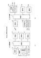
図2(1)は、撮像装置10の構成を示すブロック図であり、図2(2)は、本体装置20の構成を示すブロック図である。
図2(1)において、撮像装置10は、制御部11、電源部12、記憶部13、通信部14、操作部15、撮像部16を備えている。制御部11は、電源部(二次電池)12からの電力供給によって動作し、記憶部13内の各種のプログラムに応じてこの撮像装置10の全体動作を制御するもので、この制御部11には図示しないCPU(中央演算処理装置)やメモリなどが設けられている。記憶部13は、例えば、ROM、フラッシュメモリなどを有する構成で、本実施形態を実現するためのプログラムや各種のアプリケーションなどが格納されている。通信部14は、撮影画像を本体装置20側に送信したり、本体装置20からの操作指示信号などを受信したりする。操作部15は、電源スイッチなどの基本的な操作キー(ハードウェアキー)を備えている。
FIG. 2A is a block diagram illustrating a configuration of the
2A, the
撮像部16は、被写体を高精細に撮影可能なカメラ部を構成するもので、この撮像部16のレンズユニット16Aには、魚眼レンズ16B、撮像素子16Cなどが設けられている。なお、本実施形態のカメラは、通常の撮像レンズ(図示省略)を魚眼レンズ16Bに交換したり、その他の広角レンズ(図示省略)に交換したりすることが可能なもので、図示の例は、通常の撮像レンズに代わって魚眼レンズ16Bを装着した状態を示している。この魚眼レンズ16Bは、例えば、3枚構成のレンズ系からなり、その画角が180゜を超える広範囲な撮影(略180゜撮影)が可能な円周魚眼レンズ(全周魚眼レンズ)であり、この魚眼レンズ16Bによって撮影された広角画像(魚眼画像)の全体は、円形の画像となる。この場合、射影方式を採用しているために、魚眼レンズ16Bで撮影された広角画像(魚眼画像)は、その中心から端部に向かう程、大きく歪んだものとなる。
The
すなわち、魚眼レンズ16Bは、その画角が略180゜という広範囲な撮影が可能な円周魚眼レンズであるため、魚眼画像の全体は、円形の画像となり、その中心部から端部(周辺部)の方に向かう程、大きく歪んだものとなると共に、魚眼画像の中心部に比べてその周辺部は縮小された画像となるため、ユーザがその周辺部の内容を詳細に目視確認しょうとしてもその確認は極めて困難なものとなる。このような魚眼レンズ16Bによる被写体像(光学像)が撮像素子(例えば、CMOS又はCCD)16Cに結像されると、この撮像素子16Cによって光電変換された画像信号(アナログ値の信号)は、図示省略のA/D変換部によってデジタル信号に変換されると共に、所定の画像表示処理が施された後、本体装置20側に送信されてモニタ表示される。
That is, since the fisheye lens 16B is a circular fisheye lens capable of shooting a wide range with an angle of view of approximately 180 °, the entire fisheye image becomes a circular image, and the image from the center to the end (peripheral portion) is formed. The more it goes, the more it gets distorted, and the surrounding area is a reduced image compared to the center of the fisheye image, so even if the user tries to visually check the contents of the surrounding area in detail, Confirmation becomes extremely difficult. When a subject image (optical image) formed by the fisheye lens 16B is formed on an image sensor (for example, CMOS or CCD) 16C, an image signal (analog value signal) photoelectrically converted by the
図2(2)において、本体装置20は、魚眼レンズなどを使用して撮影された画像を再生する再生機能を有し、制御部21、電源部22、記憶部23、通信部24、操作部25、タッチ表示部26を備えている。制御部21は、電源部(二次電池)22からの電力供給によって動作し、記憶部23内の各種のプログラムに応じてこの本体装置20の全体動作を制御するもので、この制御部21には図示しないCPU(中央演算処理装置)やメモリなどが設けられている。記憶部23は、例えば、ROM、フラッシュメモリなどを有する構成で、本実施形態を実現するためのプログラムや各種のアプリケーションなどが格納されているプログラムメモリ23A、この本体装置20が動作するために必要となる各種の情報(例えば、フラグなど)を一時的に記憶するワークメモリ23Bなどを有している。
In FIG. 2B, the main body device 20 has a reproduction function of reproducing an image captured using a fisheye lens or the like, and includes a
通信部24は、撮像装置10との間で各種のデータの送受信を行う。操作部25は、図示省略の電源ボタン、レリーズボタンタン(2段押し型のボタン)、露出やシャッタスピードなどの撮影条件を設定する設定ボタンなど、押しボタン式の各種のキーを備えたもので、制御部21は、この操作部25からの入力操作信号に応じた処理を実行したり、入力操作信号を撮像装置10に対して送信したりする。タッチ表示部26は、高精細液晶などのディスプレイ26A上にタッチパネル26Bを積層配置した構成で、その表示画面は、撮影された画像(魚眼画像)をリアルタイムに表示するモニタ画面(ライブビュー画面)となったり、撮影済み画像を再生する再生画面となったりする。本体装置20側において制御部21は、撮影を指示するレリーズボタン操作(2段押し操作:本撮影操作)が行われると、魚眼画像に対して現像処理を行って撮影画像を生成すると共に、画像圧縮処理を施して標準的なファイル形式に変換した後、記憶部23の記録メディアに記録保存させる。
The
図3(1)は、魚眼レンズ16Bを用いて広角撮影する撮像装置10が撮影者の胸に装着されている状態を示し、(2)は、その状態における撮像装置10の撮影範囲を示した図である。
撮像装置10は、その裏面側に衣服などに装着可能な係止具や面ファスナなどの装着部18が設けられており、図3(1)は、撮影者の左胸の位置に撮像装置10を取り外し自在に装着した状態を示している。図3(2)は、魚眼レンズ16Bの光軸方向が重力方向に対して略直交する状態、つまり、カメラが地面に対して略垂直となるようにして撮影した場合(垂直撮りを行った場合)を示し、この撮像装置10は、上述したようにその画角が180゜を超える広範囲な撮影(略180゜撮影)が可能なために、図3(2)に示すように、撮像装置10を撮影者の左胸の位置に装着した状態で広角撮影を行うと、撮影者の一部(頭部)が広角画像(魚眼画像:静止画像)内の所定の位置(例えば、周辺上端部)に写り込んでしまう。なお、撮影者の頭部には、顎、顔、頭髪を含む。
FIG. 3A illustrates a state in which the
The
ここで、本実施形態において、本体装置20は、撮影時にその撮影範囲内に撮影者の一部分が含まれている状態で撮影された広角画像(魚眼画像:静止画像)を撮像装置10から取得し、この魚眼画像に写り込まれている撮影者の一部分(頭部)が示す方向を撮影者が注目している方向として検出し、この注目方向を撮影者の顔の向きを示す情報として魚眼画像のファイル情報(例えば、Exif情報)として書き込むようにしている。そして、その魚眼画像の再生時に、そのファイル情報から撮影者の顔の向きを示す情報(注目方向)を読み出し、この注目方向に相当する魚眼画像内における所定の領域を注目領域として特定して、この注目領域内の画像を明示するための処理を行うようにしている。 Here, in the present embodiment, the main device 20 acquires from the imaging device 10 a wide-angle image (fisheye image: still image) captured in a state where a part of the photographer is included in the imaging range at the time of imaging. Then, a direction indicated by a part (head) of the photographer reflected in the fish-eye image is detected as a direction in which the photographer is paying attention, and this direction of interest is used as information indicating the direction of the face of the photographer. It is written as file information (for example, Exif information) of a fisheye image. Then, when the fisheye image is reproduced, information (attention direction) indicating the direction of the photographer's face is read from the file information, and a predetermined area in the fisheye image corresponding to the attention direction is specified as the attention area. Thus, a process for specifying the image in the attention area is performed.
すなわち、注目領域内の画像を明示するための処理として、注目領域内の画像を魚眼画像内から切り出してその切り出した画像に対してその歪曲を補正する処理を行い、その補正画像を再生画面に表示する処理を行う。なお、魚眼画像の歪を補正する処理(魚眼歪補正処理)は、仮想球面モデル上の任意の点で接する平面をスクリーンとして、仮想球面モデル上の点を平面スクリーン上の点に座標変換することにより魚眼画像の歪を補正する技術を用いているが、この補正処理は、画像処理において一般的に用いられている周知技術を利用するようにしているため、その具体的な説明については省略するものとする。 That is, as a process for specifying the image in the region of interest, a process of cutting out the image in the region of interest from the fisheye image and correcting the distortion of the cut-out image is performed, and the corrected image is displayed on a playback screen. Perform the processing to be displayed in. The processing of correcting the distortion of the fisheye image (fisheye distortion correction processing) is performed by converting a point on the virtual spherical model into a point on the flat screen using a plane tangent at an arbitrary point on the virtual spherical model as a screen. A technique for correcting the distortion of the fisheye image by using a known technique commonly used in image processing is used for this correction processing. Shall be omitted.
次に、本実施形態における画像処理装置(デジタルカメラ)の動作概念を図4〜図6に示すフローチャートを参照して説明する。ここで、これらのフローチャートに記述されている各機能は、読み取り可能なプログラムコードの形態で格納されており、このプログラムコードにしたがった動作が逐次実行される。また、ネットワークなどの伝送媒体を介して伝送されてきた上述のプログラムコードに従った動作を逐次実行することもできる。すなわち、記録媒体の他に、伝送媒体を介して外部供給されたプログラム/データを利用して本実施形態特有の動作を実行することもできる。なお、図4及び図5、図6は、デジタルカメラの全体動作のうち、本実施形態の特徴部分の動作概要を示したフローチャートであり、この図4及び図5、図6のフローから抜けた際には、全体動作のメインフロー(図示省略)に戻る。 Next, an operation concept of the image processing apparatus (digital camera) according to the present embodiment will be described with reference to flowcharts shown in FIGS. Here, each function described in these flowcharts is stored in the form of a readable program code, and operations according to the program code are sequentially executed. Further, the operation according to the above-described program code transmitted via a transmission medium such as a network can be sequentially performed. That is, an operation unique to the present embodiment can be executed using a program / data externally supplied via a transmission medium in addition to the recording medium. 4, 5, and 6 are flowcharts showing an outline of the operation of the characteristic portion of the present embodiment in the entire operation of the digital camera, and have been omitted from the flows of FIGS. 4, 5, and 6. At this time, the process returns to the main flow (not shown) of the entire operation.
図4及び図5は、撮影モードに切り替えられた場合の本体装置20側の動作(本実施形態の特徴部分の動作)を説明するためのフローチャートである。
まず、本体装置20側の制御部21は、撮像装置10から広角画像(魚眼画像)を受信取得しながらその取得画像をライブビュー画像として表示する動作を開始する(図4のステップA1)。そして、レリーズボタンが半押し操作(1段押し込み操作:仮撮影操作)されるまで待機状態となる(ステップA2)。ここで、レリーズボタンの半押し操作が行われると(ステップA2でYES)、自動焦点調整(AF)及び自動露出調整(AE)処理を開始する(ステップA3)。
FIGS. 4 and 5 are flowcharts for explaining the operation of the main device 20 (operation of the characteristic portion of the present embodiment) when the mode is switched to the shooting mode.
First, the
そして、制御部21は、撮像装置10から魚眼画像(ライブビュー画像)を受信取得してその画像を解析しながらその魚眼画像内の所定の位置(上述の周辺上端部)に含まれている人物の顔、すなわち、撮影者の顔を検出する処理を行う(ステップA4)。この顔検出処理は、顔パーツを検出したり、肌色を検出したりするなど、カメラにおいて一般的に用いられている技術であり、本実施形態ではその周知技術を利用するようにしているため、その具体的な説明については省略するものとする。
Then, the
ここで、図3(2)に示したように撮像装置10が撮影者の胸の位置に装着されている状態で広角撮影された魚眼画像内の所定の部分(周辺上端部)には、その撮影者の一部分(顎、顔、毛髪)が写り込んでいるため、制御部21は、魚眼画像内から撮影者の顔を検出する。更に、検出した顔の中から鼻を認識して、魚眼画像内の鼻尖点の座標位置を検出すると共に(ステップA5)、撮影者の顎先を認識してその顎先の高さ(座標位置)を検出する(ステップA6)。そして、検出した鼻の位置(鼻尖点)の位置と顎先の高さ(位置)とを、本撮影時において撮影者の注目方向を判定するための判定用基準値(初期値)としてワークメモリ23Bに一時記憶(設定)しておく(ステップA7)。
Here, as shown in FIG. 3 (2), a predetermined portion (upper peripheral portion) in a wide-angle photographed fisheye image in a state where the
図7(1)、(2)は、撮像装置10が撮影者の胸の位置に装着されている状態において、撮影された魚眼画像の周辺上端部に写り込んでいる撮影者の頭部(顎、顔、毛髪)に基づいて、本撮影時における撮影者の注目方向を判定する方法を説明するための図である。
撮像装置10が撮影者の胸の位置に装着されている状態で撮影を行った場合に、撮影者の頭部は魚眼画像の周辺部に写り込むために大きく歪んだものとなるが、撮影者の顔の各部位を認識してその位置を特定することができる程度の歪みであるため、本実施形態では、撮影者の鼻尖点と顎先に着目し、その鼻尖点と顎先の位置の変化に基づいて、顔の向きを判定(検出)するようにしている。図7(1)は、魚眼画像内における撮影者の鼻尖点の位置変化を示し、図7(2)は、撮影者の顎先の位置変化を示した図で、制御部21は、鼻尖点の位置の変化を検出することにより顔の左右方向の変化を検出し、また、顎先の位置の変化を検出することによって顔の上下方向の変化を検出することによって、本撮影時における撮影者の注目方向(顔の向き)を判定するようにしている。
FIGS. 7A and 7B show the photographer's head (shown at the upper end of the periphery of the photographed fisheye image when the
When imaging is performed with the
このように本実施形態においては、撮影者の鼻尖点と顎先の位置変化に基づいて、その撮影者の注目方向(顔の向き)を判定するようにしているため、その判定基準値(初期値)としての鼻尖点と顎先の位置を予め設定しておく必要がある。上述のステップA7は、この判定基準値を設定するための処理で、レリーズボタンの半押し操作(仮撮影操作)時にその設定を行うようにしいる。このような設定処理が終わると、ステップA8に移り、レリーズボタンの全押し操作(本撮影操作)が行われるまで待機状態となる。 As described above, in the present embodiment, the attention direction (face direction) of the photographer is determined based on the change in the position of the photographer's nose tip and chin, so that the determination reference value (initial value) is determined. It is necessary to set the position of the nose tip and the chin tip as the value in advance. The above-described step A7 is a process for setting the determination reference value, and the setting is performed when the release button is half-pressed (temporary shooting operation). When such a setting process is completed, the process proceeds to step A8, and a standby state is established until the release button is fully pressed (main shooting operation).
いま、レリーズボタンが全押し操作されると(ステップA8でYES)、図5のフローに移り、撮像装置10から受信取得した魚眼画像に対して現像処理を行って撮影画像を生成すると共に、画像圧縮処理を施して標準的なファイル形式に変換した後、記憶部23の記録メディアに記録保存させる(ステップA9)。そして、上述の場合と同様に、その撮影画像(魚眼画像)を解析しながらその画像内に含まれている人物の顔を検出する(ステップA10)。更に、検出した顔の中から鼻尖点の位置を検出すると共に(ステップA11)、撮影者の顎先の位置を検出する(ステップA12)。
Now, when the release button is fully pressed (YES in step A8), the process proceeds to the flow of FIG. 5, where the fisheye image received and received from the
次に、本撮影時に検出した鼻尖点と顎先の位置と、予め設定されている判定用基準値(仮撮影時の鼻尖点と顎先の位置)とを比較し、本撮影時の鼻尖点の位置と仮撮影時の鼻尖点の位置との変位量を求めると共に、本撮影時の顎先の位置と仮撮影時の顎先の位置との変位量を求める(ステップA13)。そして、鼻尖点の変位量と顎先の変位量から本撮影時における撮影者の注目方向(顔の向き)を判定する(ステップA14)。この場合、本実施形態においては、上述の判定用基準値(仮撮影時における鼻尖点と顎先の位置)の状態を撮影者の顔が正面に向いていると状態であると仮定するようにしている。すなわち、判定用基準値の鼻尖点と顎先の位置は、左右及び上下に偏りのない正面向きの状態であると仮定し、この正面向き状態を基準点(魚眼画像の中心点)として、鼻尖点の変位量と顎先の変位量から本撮影時における撮影者の注目方向(顔の向き)を判定するようにしている。なお、基準点を魚眼画像の中心点とする場合に限らず、撮像装置10の装着位置との関係で基準点を設定するようにしてもよい。
Next, the nose apex and the position of the chin detected at the time of the main shooting are compared with a predetermined reference value for reference (the nose apex and the position of the chin at the time of the temporary shooting), and the nose apex at the time of the main shooting is compared. And the amount of displacement between the position of the nose and the position of the nose tip during the tentative photographing, and the amount of displacement between the position of the chin during the actual photographing and the position of the chin during the tentative photographing are determined (step A13). Then, the direction of interest (face direction) of the photographer at the time of the main photographing is determined from the displacement amount of the nose tip and the displacement amount of the chin (Step A14). In this case, in the present embodiment, the state of the reference values for determination (the positions of the nose cusp and the chin at the time of provisional imaging) is assumed to be a state where the face of the photographer is facing front. ing. That is, the nose apex and the position of the chin of the reference value for determination are assumed to be in a front-facing state without any deviation left and right and up and down, and this front-facing state is defined as a reference point (the center point of the fisheye image). The attention direction (face direction) of the photographer at the time of the main photographing is determined from the displacement amount of the nose tip and the displacement amount of the chin. Note that the reference point is not limited to the center point of the fisheye image, and the reference point may be set in relation to the mounting position of the
いま、仮撮影時の鼻尖点の位置をX1、本撮影時の鼻尖点の位置をX2とすると、鼻尖点の変位量ΔXは、X1−X2となる。同様に、仮撮影時の顎先の位置をY1、本撮影時の顎先の位置をY2とすると、その変位量ΔYは、Y1−Y2となる。ここで、上述のように正面向き状態を基準点(魚眼画像の中心点)とした場合には、魚眼画像の中心点からX軸方向(左右方向)に鼻尖点の変位量ΔXだけ離れ、かつ、Y軸方向(上下方向)に顎先の変位量ΔYだけ離れた位置を撮影者の注目方向(顔の向き)として判定する。なお、鼻尖点の変位量ΔXがプラスであれば右方向、マイナスであれば左方向、顎先の変位量ΔYがプラスであれば上方向、マイナスであれば下方向に変位する。 Now, assuming that the position of the nose apex at the time of provisional imaging is X1 and the position of the nose apex at the time of main imaging is X2, the displacement amount ΔX of the nose apex is X1−X2. Similarly, assuming that the position of the chin at the time of provisional imaging is Y1 and the position of the chin at the time of actual imaging is Y2, the displacement amount ΔY is Y1−Y2. Here, when the front-facing state is set as the reference point (the center point of the fisheye image) as described above, it is separated from the center point of the fisheye image by the displacement amount ΔX of the nose tip in the X-axis direction (left-right direction). In addition, a position separated by the amount of displacement ΔY of the chin in the Y-axis direction (vertical direction) is determined as the photographer's attention direction (face direction). If the displacement ΔX of the nose tip is positive, the displacement is to the right, if it is negative, it is to the left, if the displacement ΔY of the chin is positive, it is to the upward, and if it is negative, it is to the downward.
そして、検出した撮影者の注目方向(顔の向き)を画像ファイル情報(例えば、Exif情報)に書き込むと共に、撮影者の頭部が写り込んでいる方向に基づいて魚眼画像の天地方向を特定して、その魚眼画像の天地方向を画像ファイル情報に書き込む(ステップA15)。なお、本実施形態において、撮影者の頭部が写り込んでいる方向に基づいて魚眼画像の天地方向を特定しているが、それに限らず、撮像装置10にセンサーなどの姿勢検出部を設けて、当該姿勢検出部の検出結果に基づいて魚眼画像の天地方向を特定してもよい。更に、本実施形態においては、撮影者の注目方向(顔の向き)を画像ファイル情報に書き込むようにしたが、その魚眼画像に対応付けて別ファイルに記憶するようにしてもよい。その後、撮影モードが解除されて他の動作モード(撮影モードなど)に切り替えられたかを調べ(ステップA16)、撮影モードのままであれば(ステップA16でNO)、図4のステップA2に戻るが、撮影モードが解除された場合には(ステップA16でYES)、図4及び図5のフローから抜ける。 Then, the detected direction of interest (face direction) of the photographer is written in image file information (for example, Exif information), and the vertical direction of the fisheye image is specified based on the direction in which the head of the photographer is reflected. Then, the vertical direction of the fisheye image is written in the image file information (step A15). Note that, in the present embodiment, the vertical direction of the fisheye image is specified based on the direction in which the head of the photographer is reflected. However, the present invention is not limited thereto. Then, the vertical direction of the fisheye image may be specified based on the detection result of the posture detection unit. Further, in the present embodiment, the attention direction (face direction) of the photographer is written in the image file information, but may be stored in another file in association with the fisheye image. Thereafter, it is checked whether or not the shooting mode is canceled and switched to another operation mode (such as a shooting mode) (step A16). If the shooting mode is maintained (NO in step A16), the process returns to step A2 in FIG. If the shooting mode is canceled (YES in step A16), the process exits from the flowcharts of FIGS.
図6は、魚眼画像(保存済み画像)を再生する場合の本体装置20側の動作(本実施形態の特徴部分の動作)を示したフローチャートである。
まず、制御部21は、ユーザ操作によって魚眼画像(保存済み画像)の再生が指示されると、記憶部23の記録メディアに記録保存されている複数の魚眼画像(保存済み画像)を読み出すと共に(ステップB1)、サムネイル画像に変換してタッチ表示部26に一覧表示させる(ステップB2)。
FIG. 6 is a flowchart illustrating an operation (operation of a characteristic portion of the present embodiment) on the main device 20 side when a fisheye image (saved image) is reproduced.
First, when the reproduction of the fisheye image (saved image) is instructed by a user operation, the
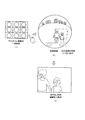
図8は、魚眼画像を再生する場合の様子を説明するための図である。
図8(1)、本体装置20側のタッチ表示部26に各種の魚眼画像(保存済み画像)がサムネイル表示された一覧画面を示した図である。図中の円形は、個々の魚眼画像を示し、3×3のマトリックス状に魚眼画像がサムネイル表示されている状態である。この状態において、この一覧画面の中から任意のサムネイル画像を再生対象として指定するタッチ操作が行われたかを調べ(ステップB3)、タッチ操作が行われなければ(ステップB3でNO)、操作部25の所定キーとして、再生終了を指示するキーが操作されたかを調べる(ステップB4)。ここで、再生終了が指示されなければ(ステップB4でNO)、上述のステップB3に戻るが、再生終了が指示された場合には(ステップB4でYES)、図6のフローから抜ける。
FIG. 8 is a diagram for explaining a state in which a fisheye image is reproduced.
FIG. 8A is a diagram illustrating a list screen in which various fisheye images (saved images) are displayed as thumbnails on the
いま、複数の魚眼画像がマトリックス状にサムネイル画像として一覧表示されている状態において、その中から任意のサムネイル画像の位置がタッチされると(ステップB3でYES)、制御部21は、その魚眼画像を再生対象として選択指定する(ステップB5)。図8(2)は、再生対象として選択された魚眼画像を示している。そして、この指定画像(魚眼画像)のファイル情報から撮影者の注目方向(顔の向き)及び天地方向を読み出し(ステップB6)、この注目方向から魚眼画像内の注目領域を切り出し枠として特定する(ステップB7)。
Now, in a state where a plurality of fish-eye images are displayed as a list of thumbnail images in a matrix, if a position of an arbitrary thumbnail image is touched (YES in step B3), the
すなわち、図8(2)は、再生対象として選択された魚眼画像内に特定した注目領域を示した図である。この場合、制御部21は、魚眼画像内において撮影者の注目方向の位置を基準(中心点)として所定サイズ(縦横比が3:4)の長方形枠を注目領域として特定する。図示の例では、撮影者が男の子に注目している場合で、その男の子を基準(中心点)として所定サイズの長方形枠(図中、破線)が注目領域として特定される。そして、次のステップB8では、上述のようにして特定した注目領域を移動する必要があるかを判別する。すなわち、特定した注目領域内から所定の被写体の一部分(例えば、人物の頭部)がはみ出しているか、又は、注目領域が魚眼画像の外側に所定量以上はみ出しているかを判別する。
That is, FIG. 8B is a diagram illustrating the attention area specified in the fisheye image selected as the reproduction target. In this case, the
ここで、特定した注目領域内から所定の被写体の一部分(例えば、人物の頭部)がはみ出している場合には(ステップB8でYES)、その被写体の一部分が注目領域内に収まるようにその注目領域を移動する(ステップB9)。また、注目領域が魚眼画像の外側に所定量以上(例えば、30%以上)はみ出している場合には(ステップB8でYES)、そのはみ出し量が少なくなるように(例えば、20%以下となるように)、注目領域を広角画像(魚眼画像)の内側方向に移動する(ステップB9)。 Here, when a part of a predetermined subject (for example, the head of a person) protrudes from the specified attention area (YES in step B8), the attention is set so that the part of the subject falls within the attention area. The area is moved (step B9). When the region of interest is outside the fisheye image by a predetermined amount or more (for example, 30% or more) (YES in step B8), the amount of the protrusion is reduced (for example, 20% or less). As described above, the attention area is moved inward of the wide-angle image (fisheye image) (step B9).
図9(1)は、注目領域内から人物の頭部がはみ出している場合を例示したもので、図中、破線の長方形は、移動前の注目領域を示し、実線の長方形は、移動後の注目領域を示したもので、注目領域を図中、上方向に移動することによって人物の頭部は、注目領域内に収まるようになる。図9(2)は、注目領域が魚眼画像の外側に所定量以上はみ出している場合を例示したもので、図中、破線の長方形は、移動前の注目領域を示し、実線の長方形は、移動後の注目領域を示したもので、注目領域を図中、下方向に移動することによって移動前の注目領域内には魚眼画像が略50%しか含まれていなかったが、移動後の魚眼画像には魚眼画像が略80%含まれるようになる。なお、本実施形態では、注目領域が魚眼画像の外側に所定量以上はみ出している場合には、そのはみ出し量が少なくなるように、注目領域を広角画像(魚眼画像)の内側方向に移動させているが、そのはみ出し量が全く無くなるまで、注目領域の全体を魚眼画像の内側に含まれるように、当該注目領域を移動させてもよい。 FIG. 9A illustrates an example in which the head of the person protrudes from the attention area. In the figure, a dashed rectangle indicates the attention area before movement, and a solid rectangle indicates the movement area after movement. The region of interest is shown, and by moving the region of interest upward in the figure, the head of the person will fall within the region of interest. FIG. 9 (2) illustrates a case where the attention area protrudes beyond the fisheye image by a predetermined amount or more. In the figure, a dashed rectangle indicates the attention area before movement, and a solid rectangle indicates This shows the attention area after the movement. By moving the attention area downward in the figure, the attention area before the movement contained only about 50% of the fisheye image. The fisheye image contains approximately 80% of the fisheye image. In the present embodiment, when the region of interest protrudes beyond the fish-eye image by a predetermined amount or more, the region of interest is moved inward of the wide-angle image (fish-eye image) so as to reduce the amount of protrusion. However, the attention area may be moved so that the entire attention area is included inside the fisheye image until the amount of protrusion is completely eliminated.
このようにして特定した注目領域に基づいて魚眼画像からその注目領域(切り出し枠)内の画像を切り出す(ステップB10)。なお、注目領域(切り出し枠)は、長方形に限らず、楕円などであってもよく、その形状は問わない。そして、その切り出した画像に対してその歪曲を補正する処理(ステップB11)を施した後、その魚眼画像のファイル情報から読み出した天地方向に基づいて魚眼画像の天地を判断して再生画面に拡大表示させる(ステップB12)。図8(3)は、注目領域(切り出し枠)内の画像が拡大表示された状態を示している。 Based on the region of interest specified in this way, an image within the region of interest (cutout frame) is cut out from the fisheye image (step B10). Note that the region of interest (cutout frame) is not limited to a rectangle, and may be an ellipse or the like, and its shape does not matter. Then, after performing the processing (step B11) for correcting the distortion on the cut-out image, the reproduction screen is determined by judging the top and bottom of the fish-eye image based on the top and bottom direction read from the file information of the fish-eye image. (Step B12). FIG. 8C shows a state in which the image in the attention area (cutout frame) is enlarged and displayed.
そして、他の魚眼画像の表示を指示する操作(画像の切り替えを指示する操作)が行われたかを調べたり(ステップB13)、画像再生の終了を指示する操作が行われたかを調べたりする(ステップB14)。いま、再生終了が指示された場合には(ステップB14でYES)、図6のフローから抜けるが、他の魚眼画像への切り替え表示を指示する切替操作が行われた場合には(ステップB13でYES)、上述したサムネイル画像を一覧表示するステップA2に戻り、以下、上述の動作を繰り返す。 Then, it is determined whether or not an operation for instructing display of another fisheye image (operation for instructing image switching) has been performed (step B13), and whether or not an operation for instructing termination of image reproduction has been performed. (Step B14). If the end of reproduction is instructed (YES in step B14), the process exits from the flow of FIG. 6, but if a switching operation for instructing switching display to another fisheye image is performed (step B13). YES), the process returns to step A2 for displaying a list of thumbnail images described above, and thereafter, the above-described operation is repeated.
以上のように、本実施形態において本体装置20の制御部21は、撮影時にその撮影範囲内に撮影者の一部分が含まれている状態で広角撮影された広角画像(魚眼画像)を撮像装置10から取得して、この広角画像(魚眼画像)に写り込まれている撮影者の一部分に基づく魚眼画像内の所定の領域を撮影者が注目している注目領域として特定し、この注目領域内の画像を明示するための処理を行うようにしたので、撮影者が何に注目して広角撮影を行ったのかを容易に確認することができる。
As described above, in the present embodiment, the
制御部21は、魚眼画像内に写り込まれている撮影者の一部分に基づいて、撮影時にその撮影範囲内で撮影者が注目している方向を検出し、この注目方向に相当する魚眼画像内における所定の領域を注目領域として特定するようにしたので、広角時に撮影者の状態に応じた注目方向から魚眼画像内の注目領域を適切に特定することができる。
The
制御部21は、撮影者の注目方向を基準として、魚眼画像内における所定サイズの領域を注目領域として特定するようにしたので、撮影者の注目対象を基準として注目領域として特定することができる。
The
制御部21は、注目領域内から所定の被写体の一部分(人物の頭部)がはみ出している場合には、その被写体の一部分が注目領域内に収まるようにその注目領域を移動するようにしたので、注目方向を精度良く検出することができなくても注目領域内に人物の顔を収めることが可能となる。
When a part of a predetermined subject (a person's head) protrudes from the attention area, the
制御部21は、注目領域が魚眼画像の外側に所定量以上はみ出している場合には、その注目領域を魚眼画像の内側方向に移動するようにしたので、たとえ注目方向を精度良く検出することができなくても注目領域内から魚眼画像が大きく外れることを防ぐことが可能となる。
When the region of interest protrudes beyond the fisheye image by a predetermined amount or more, the
制御部21は、レリーズボタンが半押し操作(仮撮影操作)時にその撮影範囲内に撮影者の一部分が含まれている状態で撮影された魚眼画像を取得し、かつ、レリーズボタンが全押し操作(本撮影操作)時にその撮影範囲内に撮影者の一部分が含まれている状態で広角撮影された魚眼画像を取得し、仮撮影時に撮影された魚眼画像内に写り込まれている撮影者の一部分と本撮影時に撮影された魚眼画像内に写り込まれている撮影者の一部分とを比較し、その変化状態に基づいて、本撮影時にその撮影範囲内で撮影者が注目している方向を検出するようにしたので、撮影者の注目方向を適切に検出することができる。
When the release button is half-pressed (temporary shooting operation), the
制御部21は、撮影者の胸に撮像装置10が装着されている状態で撮影された魚眼画像を取得し、この魚眼画像に写り込まれている撮影者の顔部分に基づいて、撮影者が注目している方向を検出するようにしたので、撮影者の顔部分からその注目方向を適切に検出することができる。
The
制御部21は、魚眼画像内に写り込まれている撮影者の位置に基づいて、その魚眼画像の天地方向を検出するようにしたので、撮影者の位置を画像フォルダ情報に画像方向として天地方向を書き込むことができる。
なお、撮像装置10に姿勢検出部を設け、その姿勢検出部の検出結果に基づいて魚眼画像の天地方向を特定するようにすれば、天地方向の特定が確実なものとなる。
The
It should be noted that if the
制御部21は、注目領域内の画像を明示するための処理として、魚眼画像内から注目領域内の画像を切り出す処理を行うようにしたので、撮影範囲が広範囲であってもその中から注目領域内の画像のみを抽出することができる。
The
制御部21は、注目領域内の画像を明示するための処理として、魚眼画像の注目領域内内の画像に対してその歪を補正する処理を行うようにしたので、注目領域内の画像のみを歪のない画像とすることができる。
The
(変形例1)
上述した実施形態においては、撮影者の注目方向を基準(中心)として、魚眼画像内における所定サイズの領域を注目領域として特定して、その注目領域内の画像を切り出すようにしたが、魚眼画像を予め複数の領域に論理的に分割(例えば、広角画像を3×3のマトリックス状に分割)しておき、この複数の分割領域の中から撮影者の注目方向に相当するいずれかの分割領域を注目領域として特定し、その注目領域内の画像を切り出すようにしてもよい。
(Modification 1)
In the above-described embodiment, an area of a predetermined size in the fisheye image is specified as an attention area with the photographer's attention direction as a reference (center), and an image in the attention area is cut out. The eye image is logically divided in advance into a plurality of regions (for example, a wide-angle image is divided into a 3 × 3 matrix), and any one of the plurality of divided regions corresponding to the direction of interest of the photographer is selected. The divided region may be specified as a region of interest, and an image in the region of interest may be cut out.
すなわち、9つの分割領域を“正面向き”、“正面上向き”、“正面下向き”、“右横向き”、“右上向き”、“右下向き”、“左横向き”、“左上向き”、“左下向き”の領域とし、その中から注目方向が属する分割領域を注目領域(切り出し枠)として特定して、その枠内の画像を切り出すようにしてもよい。なお、例えば、鼻尖点の変位量を左右方向(X軸方向)、顎先の変位量を上下方向(Y軸方向)として、上述の各分割領域を対応付けたテーブル(図示省略)を参照して、注目方向が属する分割領域を注目領域として特定するようにしてもよい。 That is, the nine divided regions are defined as “front facing”, “front facing up”, “front facing down”, “right side facing”, “upper right facing”, “right down facing”, “left lateral facing”, “left upper facing”, “down left facing” , A divided area to which the direction of interest belongs may be specified as a region of interest (cutout frame), and an image in that frame may be cut out. Note that, for example, the displacement amount of the nose tip is defined as the left-right direction (X-axis direction), and the displacement amount of the chin is defined as the up-down direction (Y-axis direction), and a table (not shown) associating the above-described divided regions is referred to. Then, the divided area to which the attention direction belongs may be specified as the attention area.
この場合、魚眼画像は円形であるため、例えば、“右上向き”、“右下向き”、“左上向き”、“左下向き”の分割領域(斜め方向の分割領域)のいずれかが魚眼画像の外側からはみ出してしまう場合には、上述した実施形態と同様に、その分割領域をそのまま注目領域(切り出し枠)として特定せずに、分割領域を魚眼画像の内側に所定距離移動した領域を注目領域(切り出し枠)として特定するようにしてもよい。また、撮影者の注目方向に相当する分割領域内の所定の被写体(例えば、人物の頭部)がその分割領域からはみ出している場合には、その人物の頭部全体がその分割領域内に収まるように移動した領域を注目領域(切り出し枠)として特定するようにしてもよい。 In this case, since the fisheye image is circular, for example, any one of the divided regions (diagonal divided regions) of “upper right”, “downright”, “upper left”, and “lower left” is a fisheye image. In this case, as in the above-described embodiment, the divided region is not specified as the region of interest (cutout frame), and the region in which the divided region is moved by a predetermined distance inside the fisheye image is used. You may make it specify as an attention area (cutout frame). Further, when a predetermined subject (for example, the head of a person) in the divided area corresponding to the direction of the photographer's attention protrudes from the divided area, the entire head of the person falls within the divided area. The moved region may be specified as the region of interest (cutout frame).
また、上述のように魚眼画像を予め複数の領域に分割する場合においても、第1実施形態と同様に、注目領域内から所定の被写体の一部分(人物の頭部)がはみ出している場合には、その被写体の一部分が注目領域内に収まるようにその注目領域を移動するようにしたので、注目方向を精度良く検出することができなくても注目領域内に人物の顔を収めることが可能となる。更に、注目領域が広角画像の外側に所定量以上はみ出している場合には、その注目領域を魚眼画像の内側方向に移動するようにしたので、注目方向を精度良く検出することができなくても注目領域内から魚眼画像が大きく外れることを防ぐことが可能となる。 Also, when the fisheye image is divided into a plurality of regions in advance as described above, similarly to the first embodiment, when a part of a predetermined subject (the head of a person) protrudes from the attention region. Moves the region of interest so that a part of the subject falls within the region of interest, so it is possible to fit the face of a person in the region of interest even if the direction of interest cannot be detected accurately. Becomes Furthermore, when the region of interest protrudes beyond the wide-angle image by a predetermined amount or more, the region of interest is moved inward of the fisheye image, so that the direction of interest cannot be accurately detected. It is also possible to prevent the fisheye image from largely deviating from the attention area.
このように魚眼画像を予め複数の領域に分割しておき、撮影者の注目方向に相当するいずれかの分割領域を注目領域として特定するようにすれば、注目領域の特定が容易となると共に、注目領域を一律に特定することが可能となる。 In this way, if the fisheye image is divided into a plurality of regions in advance and any of the divided regions corresponding to the photographer's direction of interest is specified as the region of interest, the region of interest can be easily specified. Thus, the attention area can be specified uniformly.
更に、注目領域を特定する方法としては、撮影者の一部分の撮影前後の位置変化、又は形状変化、又は面積変化に基づいて魚眼画像内の所定の領域を撮影者が注目している注目領域として特定するにしてもよい。このように各種の特定方法を可能とすることにより、その中から複数の特定方法を組み合わせて注目領域を多角的に特定したり、特定方法を撮影状況に応じて切り換えたりすることができる。 Further, as a method of specifying a region of interest, a region of interest in which the photographer is paying attention to a predetermined region in the fisheye image based on a position change before or after photographing a part of the photographer, or a shape change or an area change May be specified. By enabling various specifying methods in this way, a plurality of specifying methods can be combined from among them to specify a region of interest from multiple angles, or to switch the specifying method according to a shooting situation.
(変形例2)
上述した実施形態においては、撮影者の注目方向を基準(中心)に基づいて特定した注目領域を切り出し枠として特定し、その枠内の画像を切り出すようにしたが、注目領域内の画像を明示する処理としては、これに限らず、例えば、魚眼画像又はその補正画像内の注目領域に指標を付加(重畳)するようにしてもよいし、これらを組み合わせてもよい。例えば、注目領域に識別可能な枠を付加したり、注目領域内に特別な記号や図形などを付加したり、注目領域内の画像の輝度を高めたりするようにしてもよい。このように注目領域を識別可能に表示するようにすれば、ユーザは画像再生によってその画像全体を確認しながら撮影者が何に注目していたかを併せて知ることができる。
(Modification 2)
In the above-described embodiment, the attention area specified based on the reference (center) of the photographer's attention direction is specified as a cutout frame, and the image in the frame is cut out. The processing to be performed is not limited to this. For example, an index may be added (superimposed) to a target area in a fisheye image or its corrected image, or a combination of these may be used. For example, an identifiable frame may be added to the region of interest, a special symbol or figure may be added to the region of interest, or the brightness of the image in the region of interest may be increased. If the attention area is displayed so as to be identifiable in this way, the user can also know what the photographer was paying attention to while checking the entire image by image reproduction.
なお、上述した実施形態においては、1台のカメラで撮影された魚眼画像に対してその撮影者の注目方向を検出してその注目方向に相当する注目領域を特定するようにしたが、これに限らず、撮影者が複数台のカメラを装着し、各カメラで撮影された画像を合成して広角画像を生成する場合にも適用可能である。このことは、更に、撮影範囲が連続するように1台のカメラで順次撮影された各撮影画像を順次合成して広角画像を生成する場合においても同様である。 In the above-described embodiment, an attention direction of the photographer is detected with respect to a fisheye image captured by one camera, and an attention area corresponding to the attention direction is specified. However, the present invention is not limited to this, and is also applicable to a case where a photographer wears a plurality of cameras and combines images taken by each camera to generate a wide-angle image. This is the same when a wide-angle image is generated by sequentially synthesizing captured images sequentially captured by one camera so that the imaging range is continuous.
上述した実施形態においては、魚眼レンズ16Bを用いて静止画撮影を行う場合を例示したが、動画撮影を行う場合であっても同様に適用可能である。この場合、本撮影時に撮影者の注目方向を1フレーム毎に検出して注目領域を切り出し枠として特定し、この注目領域(切り出し枠)内の画像をフレーム毎に再生するようにすればよい。この場合、動画(魚眼画像)の再生時に撮影者の注目方向が変化したときのみ注目領域を特定して魚眼画像と共に、又は魚眼画像に代えて注目領域から切り出した画像を再生するようにしてもよい。 In the above-described embodiment, the case where still image shooting is performed using the fisheye lens 16B has been described as an example, but the present invention is similarly applicable to the case where moving image shooting is performed. In this case, the direction of interest of the photographer may be detected for each frame at the time of actual photographing, the area of interest may be specified as a cutout frame, and the image in the area of interest (cutout frame) may be reproduced for each frame. In this case, an attention area is specified and the image cut out from the attention area is reproduced together with the fisheye image or in place of the fisheye image only when the direction of the photographer's attention changes during reproduction of the moving image (fisheye image). It may be.
上述した実施形態においては、人物の顔を検出して、鼻尖点及び顎先の位置から撮影者の注目方向を特定するようにしたが、これに限らず、目の位置など顔のどの部位を基準として撮影者の注目方向を特定するかは問わない。また、鼻尖点などの変位量から撮影者の注目方向を特定する場合に限らず、例えば、鼻の形状変化や面積変化などの変移量から撮影者の注目方向を特定するようにしてもよい。更に、撮影者の瞳を検出してその視線方向を注目方向として特定するようにすれば、撮影者が顔を動かさずに視線方向のみを変えた場合でもその視線方向を注目方向として特定することが可能となる。 In the embodiment described above, the face of the person is detected, and the direction of interest of the photographer is specified from the positions of the nose tip and the chin. However, the present invention is not limited to this. It does not matter whether the attention direction of the photographer is specified as a reference. Further, the present invention is not limited to the case where the photographer's attention direction is specified based on the displacement amount such as the nose point, and the photographer's attention direction may be specified based on a change amount such as a nose shape change or an area change. Furthermore, if the photographer's pupil is detected and its gaze direction is specified as the direction of interest, the gaze direction can be specified as the direction of interest even if the photographer changes only the gaze direction without moving the face. Becomes possible.
上述した実施形態においては、撮影体として人間を前提としたが、撮影体は人間に限らず、視覚、聴覚、触覚など感覚機能を有する知能ロボットの判断能力を基に撮影を行う場合であってもよい。また、上述した実施形態においては、撮影者の一部として、人物の顔を例示したが、撮影者の指、腕、足などによるジェスチャを検出するようにしてもよい。 In the above-described embodiment, the photographing object is assumed to be a human, but the photographing object is not limited to a human, and the photographing is performed based on the judgment ability of an intelligent robot having sensory functions such as sight, hearing, and touch. Is also good. Further, in the above-described embodiment, a person's face is exemplified as a part of the photographer, but a gesture by a photographer's finger, arm, foot, or the like may be detected.
また、上述した実施形態においては、撮影範囲が略180°の魚眼レンズ16Bを用いて撮影した魚眼画像に適用した場合を例示したが、360°撮影の魚眼画像に適用するようにしてもよい。例えば、360°撮影として前方180°撮影と後方180°撮影の2回に分けて撮影することにより得られた魚眼画像に適用したり、略180°の魚眼レンズ16Bを筐体の前後両面(表裏両面)にそれぞれ備えたカメラによって前後両方を一度に撮影することにより得られた魚眼画像に適用したりしてもよい。 Further, in the above-described embodiment, the case where the present invention is applied to the fisheye image photographed using the fisheye lens 16B having the photographing range of about 180 ° is illustrated, but the present invention may be applied to the fisheye image photographed by 360 °. . For example, the present invention can be applied to a fisheye image obtained by performing two shots of 360 ° shooting, 180 ° forward shooting and 180 ° rearward shooting, or a fisheye lens 16B of approximately 180 ° can be attached to the front and rear surfaces (front and back) of the housing. Alternatively, the present invention may be applied to a fisheye image obtained by photographing both front and rear portions at a time by cameras provided on both sides.
上述した実施形態においては、撮像装置10を撮影者の胸に装着するようにしたが、これに限らず、例えば、帽子の鍔の先に装着したり、腰のベルトに装着したり、更には、ウエアラブルカメラに限らず、定置して撮影を行うカメラに適用可能である。
In the above-described embodiment, the
上述した実施形態においては、魚眼レンズ16Bを用いて魚眼画像を撮影する場合を例示したが、魚眼レンズ16B以外の広角レンズを使用して広角撮影した広角画像に対しても適用可能である。 In the above-described embodiment, the case where the fisheye image is photographed using the fisheye lens 16B has been described as an example. However, the present invention is also applicable to a wide-angle image photographed using a wide-angle lens other than the fisheye lens 16B.
また、上述した実施形態においては、画像処理装置としてデジタルカメラに適用した場合を示したが、これに限らず、パーソナルコンピュータ、PDA(個人向け携帯型情報通信機器)、タブレット端末装置、スマートフォンなどの携帯電話機、電子ゲーム、音楽プレイヤーなどであってもよい。 Further, in the above-described embodiment, the case where the present invention is applied to a digital camera as an image processing apparatus has been described. However, the present invention is not limited to this, and may be applied to a personal computer, a PDA (personal portable information communication device), a tablet terminal device, a smartphone, etc. It may be a mobile phone, an electronic game, a music player, or the like.
また、上述した実施形態において示した“装置”や“部”とは、機能別に複数の筐体に分離されていてもよく、単一の筐体に限らない。また、上述したフローチャートに記述した各ステップは、時系列的な処理に限らず、複数のステップを並列的に処理したり、別個独立して処理したりするようにしてもよい。 Further, the “apparatus” and “unit” shown in the above-described embodiment may be separated into a plurality of housings according to functions, and are not limited to a single housing. In addition, each step described in the above-described flowchart is not limited to time-series processing, and a plurality of steps may be processed in parallel or separately and independently.
以上、この発明の実施形態について説明したが、この発明は、これに限定されるものではなく、特許請求の範囲に記載された発明とその均等の範囲を含むものである。
以下、本願出願の特許請求の範囲に記載された発明を付記する。
(付記)
(請求項1)
請求項1に記載の発明は、
撮影時にその撮影範囲内に撮影体の一部分が含まれている状態で広角撮影された広角画像を取得する取得手段と、
前記取得手段によって取得された前記広角画像に写り込まれている前記撮影体の一部分に基づく前記広角画像内の所定の領域を前記撮影体が注目している注目領域として特定する特定手段と、
前記特定手段によって特定された前記注目領域内の画像を明示するための処理を行う処理手段と、
を備えることを特徴とする画像処理装置である。
(請求項2)
請求項2に記載の発明は、請求項1に記載の画像処理装置において、
前記取得手段によって取得された前記広角画像内に写り込まれている前記撮影体の一部分に基づいて、撮影時にその撮影範囲内で前記撮影体が注目している方向を検出する第1の検出手段を更に備え、
前記特定手段は、前記第1の検出手段によって検出された前記撮影体の注目方向に相当する前記広角画像内における所定の領域を前記注目領域として特定する、
ことを特徴とする。
(請求項3)
請求項3に記載の発明は、請求項1又は2に記載の画像処理装置において、
前記特定手段は、特定した前記注目領域内から所定の被写体の一部分がはみ出している場合には、その被写体の一部分が前記注目領域内に収まるようにその注目領域を移動する、
ことを特徴とする。
(請求項4)
請求項4に記載の発明は、請求項1乃至3のいずれか1項に記載の画像処理装置において、
前記特定手段は、特定した前記注目領域が広角画像の外側にはみ出している場合には、その注目領域を広角画像の内側方向に移動する、
ことを特徴とする。
(請求項5)
請求項5に記載の発明は、請求項2乃至4のいずれか1項に記載の画像処理装置において、
前記取得手段は、仮撮影時にその撮影範囲内に前記撮影体の一部分が含まれている状態で広角撮影された広角画像を取得し、かつ、本撮影時にその撮影範囲内に前記撮影体の一部分が含まれている状態で広角撮影された広角画像を取得し、
前記第1の検出手段は、前記仮撮影時に撮影された広角画像内に写り込まれている前記撮影体の一部分と前記本撮影時に撮影された広角画像内に写り込まれている前記撮影体の一部分とを比較し、その変化状態に基づいて、前記本撮影時にその撮影範囲内で撮影体が注目している方向を検出する、
ことを特徴とする。
(請求項6)
請求項6に記載の発明は、請求項2乃至5のいずれか1項に記載の画像処理装置において、
前記撮影体の胸に装着されている状態において広角撮影を行う撮影手段を備え、
前記取得手段は、前記撮影手段による広角撮影時にその撮影範囲内に前記撮影体の顔部分が含まれている状態で広角撮影された広角画像を取得し、
前記第1の検出手段は、前記取得手段によって取得された前記広角画像に写り込まれている前記撮影体の顔部分に基づいて、当該撮影体が注目している方向を検出する、
ことを特徴とする。
(請求項7)
請求項7に記載の発明は、請求項1乃至6のいずれか1項に記載の画像処理装置において、
前記広角画像の天地方向を検出する第2の検出手段を更に備え、
前記処理手段は、更に、前記第2の検出手段によって検出された広角画像の前記天地方向にしたがって前記注目領域内の画像を明示するための処理を行う、
ことを特徴とする。
(請求項8)
請求項8に記載の発明は、請求項7に記載の画像処理装置において、
前記第2の検出手段は、前記取得手段によって取得された広角画像内に写り込まれている前記撮影体の位置に基づいて、その広角画像の天地方向を検出する、
ことを特徴とする。
(請求項9)
請求項9に記載の発明は、請求項1乃至8のいずれか1項に記載の画像処理装置において、
前記処理手段は、前記特定手段によって特定された注目領域内の画像を明示するための処理として、前記広角画像内から前記注目領域内の画像を切り出す処理を行う、
ことを特徴とする。
(請求項10)
請求項10に記載の発明は、請求項1乃至9のいずれか1項に記載の画像処理装置において、
前記処理手段は、前記特定手段によって特定された注目領域内の画像を明示するための処理として、前記広角画像の注目領域内の画像に対してその歪を補正する処理を行う、
ことを特徴とする。
(請求項11)
請求項11に記載の発明は、請求項1乃至10のいずれか1項に記載の画像処理装置において、
前記処理手段は、前記特定手段によって特定された注目領域内の画像を明示するための処理として、前記広角画像内の注目領域を識別可能に表示する処理を行う、
ことを特徴とする。
(請求項12)
請求項12に記載の発明は、請求項1乃至11のいずれか1項に記載の画像処理装置において、
前記特定手段は、前記取得手段によって取得された前記広角画像に写り込まれている前記撮影体の一部分の撮影前後の位置変化、又は形状変化、又は面積変化に基づいて前記広角画像内の所定の領域を前記撮影体が注目している注目領域として特定する、
ことを特徴とする。
(請求項13)
請求項13に記載の発明は、
画像処理装置における画像処理方法であって、
撮影時にその撮影範囲内に撮影体の一部分が含まれている状態で広角撮影された広角画像を取得する処理と、
前記取得された広角画像に写り込まれている前記撮影体の一部分に基づく前記広角画像内の所定の領域を前記撮影体が注目している注目領域として特定する処理と、
前記特定された注目領域内の画像を明示するための処理と、
を含むことを特徴とする。
(請求項14)
請求項14に記載の発明は、
画像処理装置のコンピュータに対して、
撮影時にその撮影範囲内に撮影体の一部分が含まれている状態で広角撮影された広角画像を取得する機能と、
前記取得された広角画像に写り込まれている前記撮影体の一部分に基づく前記広角画像内の所定の領域を前記撮影体が注目している注目領域として特定する機能と、
前記特定された注目領域内の画像を明示するための処理を行う機能と、
を実現させるためのプログラムである。
The embodiments of the present invention have been described above. However, the present invention is not limited to the embodiments, and includes the inventions described in the claims and equivalents thereof.
Hereinafter, the inventions described in the claims of the present application will be additionally described.
(Note)
(Claim 1)
The invention described in
Acquisition means for acquiring a wide-angle image captured at a wide angle while a part of the imaging body is included in the imaging range at the time of imaging,
An identification unit that identifies a predetermined area in the wide-angle image based on a part of the imaging object reflected in the wide-angle image acquired by the acquisition unit as an attention area in which the imaging object is focused;
A processing unit for performing a process for specifying an image in the attention area specified by the specifying unit;
An image processing apparatus comprising:
(Claim 2)
According to a second aspect of the present invention, in the image processing apparatus according to the first aspect,
First detecting means for detecting a direction in which the photographing object is focused in the photographing range at the time of photographing, based on a part of the photographing object reflected in the wide-angle image acquired by the acquiring means; Further comprising
The specifying means specifies, as the attention area, a predetermined area in the wide-angle image corresponding to the attention direction of the imaging object detected by the first detection means,
It is characterized by the following.
(Claim 3)
According to a third aspect of the present invention, in the image processing apparatus according to the first or second aspect,
The specifying means, when a part of the predetermined subject is out of the specified attention area, moves the attention area so that a part of the subject falls within the attention area,
It is characterized by the following.
(Claim 4)
According to a fourth aspect of the present invention, in the image processing apparatus according to any one of the first to third aspects,
When the specified region of interest extends outside the wide-angle image, the specifying unit moves the region of interest inward of the wide-angle image.
It is characterized by the following.
(Claim 5)
According to a fifth aspect of the present invention, in the image processing apparatus according to any one of the second to fourth aspects,
The obtaining means obtains a wide-angle image obtained by wide-angle shooting in a state where a part of the shooting object is included in the shooting range during provisional shooting, and a part of the shooting object within the shooting range during main shooting. Obtain a wide-angle image captured with
The first detection unit is configured to detect a part of the photographed object reflected in the wide-angle image photographed during the provisional photographing and a part of the photographed object photographed in the wide-angle image photographed during the main photographing. Compare with a part, based on the change state, to detect the direction that the photographing body is paying attention in the shooting range at the time of the main shooting,
It is characterized by the following.
(Claim 6)
According to a sixth aspect of the present invention, in the image processing apparatus according to any one of the second to fifth aspects,
An imaging unit for performing wide-angle imaging while being attached to the chest of the imaging body,
The obtaining means obtains a wide-angle image obtained by wide-angle shooting in a state in which a face portion of the shooting body is included in the shooting range during wide-angle shooting by the shooting means,
The first detection unit detects a direction in which the imaging body is focused, based on a face portion of the imaging body reflected in the wide-angle image acquired by the acquisition unit,
It is characterized by the following.
(Claim 7)
According to a seventh aspect of the present invention, in the image processing apparatus according to any one of the first to sixth aspects,
A second detection unit that detects a vertical direction of the wide-angle image,
The processing unit further performs a process for specifying an image in the region of interest in accordance with the vertical direction of the wide-angle image detected by the second detection unit.
It is characterized by the following.
(Claim 8)
According to an eighth aspect of the present invention, in the image processing apparatus according to the seventh aspect,
The second detection unit detects a top-to-bottom direction of the wide-angle image based on a position of the imaging object reflected in the wide-angle image acquired by the acquisition unit.
It is characterized by the following.
(Claim 9)
According to a ninth aspect of the present invention, in the image processing apparatus according to any one of the first to eighth aspects,
The processing unit performs a process of cutting out an image in the region of interest from the wide-angle image, as a process for specifying an image in the region of interest specified by the specifying unit.
It is characterized by the following.
(Claim 10)
According to a tenth aspect of the present invention, in the image processing apparatus according to any one of the first to ninth aspects,
The processing unit performs a process of correcting the distortion of an image in the region of interest of the wide-angle image, as a process for specifying the image in the region of interest specified by the specifying unit.
It is characterized by the following.
(Claim 11)
According to an eleventh aspect of the present invention, in the image processing apparatus according to any one of the first to tenth aspects,
The processing unit performs a process of identifiably displaying a region of interest in the wide-angle image, as a process for specifying an image in the region of interest specified by the specifying unit.
It is characterized by the following.
(Claim 12)
According to a twelfth aspect of the present invention, in the image processing apparatus according to any one of the first to eleventh aspects,
The identification unit is configured to determine a predetermined position in the wide-angle image based on a position change before or after imaging of a part of the imaging body reflected in the wide-angle image acquired by the acquisition unit, or a shape change, or an area change. Identifying an area as a region of interest to which the imaging object is paying attention,
It is characterized by the following.
(Claim 13)
The invention according to
An image processing method in an image processing device,
A process of acquiring a wide-angle image obtained by capturing a wide-angle image in a state where a part of the photographing object is included in the photographing range at the time of photographing;
A process of identifying a predetermined area in the wide-angle image based on a part of the imaging body reflected in the obtained wide-angle image as a region of interest to which the imaging body is paying attention;
A process for specifying an image in the specified region of interest;
It is characterized by including.
(Claim 14)
The invention according to
For the computer of the image processing device,
A function of acquiring a wide-angle image obtained by wide-angle shooting in a state where a part of the shooting object is included in the shooting range at the time of shooting,
A function of identifying a predetermined area in the wide-angle image based on a part of the imaging body reflected in the acquired wide-angle image as a region of interest to which the imaging body is focusing;
A function of performing a process for specifying an image in the specified attention area,
It is a program for realizing.
10 撮像装置
20 本体装置
11、21 制御部
13、23 記憶部
23A プログラムメモリ
14、24 通信部
16 撮像部
16B 魚眼レンズ
16C 撮像素子
25 操作部
26 タッチ表示部
Claims (16)
前記取得手段によって取得された前記広角画像に写り込まれている前記撮影体の一部分に基づく前記広角画像内の所定の領域を前記撮影体が注目している注目領域として特定する特定手段と、
前記特定手段によって特定された前記注目領域内の画像を明示するための処理を行う処理手段と、
を備え、
前記特定手段は、特定した前記注目領域内から所定の被写体の一部分がはみ出している場合には、その被写体の一部分が前記注目領域内に収まるようにその注目領域を移動する、
ことを特徴とする画像処理装置。 Acquisition means for acquiring a wide-angle image captured at a wide angle while a part of the imaging body is included in the imaging range at the time of imaging,
An identification unit that identifies a predetermined area in the wide-angle image based on a part of the imaging object reflected in the wide-angle image acquired by the acquisition unit as an attention area in which the imaging object is focused;
A processing unit for performing a process for specifying an image in the attention area specified by the specifying unit;
Equipped with a,
The specifying means, when a part of the predetermined subject is out of the specified attention area, moves the attention area so that a part of the subject falls within the attention area,
An image processing apparatus characterized by the above-mentioned.
前記取得手段によって取得された前記広角画像に写り込まれている前記撮影体の一部分に基づく前記広角画像内の所定の領域を前記撮影体が注目している注目領域として特定する特定手段と、
前記特定手段によって特定された前記注目領域内の画像を明示するための処理を行う処理手段と、
を備え、
前記特定手段は、特定した前記注目領域が広角画像の外側にはみ出している場合には、その注目領域を広角画像の内側方向に移動する、
ことを特徴とする画像処理装置。 Acquisition means for acquiring a wide-angle image captured at a wide angle while a part of the imaging body is included in the imaging range at the time of imaging,
An identification unit that identifies a predetermined area in the wide-angle image based on a part of the imaging object reflected in the wide-angle image acquired by the acquisition unit as an attention area in which the imaging object is focused;
A processing unit for performing a process for specifying an image in the attention area specified by the specifying unit;
Equipped with a,
When the specified region of interest extends outside the wide-angle image, the specifying unit moves the region of interest inward of the wide-angle image.
An image processing apparatus characterized by the above-mentioned.
前記特定手段は、前記第1の検出手段によって検出された前記撮影体の注目方向に相当する前記広角画像内における所定の領域を前記注目領域として特定する、
ことを特徴とする請求項1又は2に記載の画像処理装置。 First detecting means for detecting a direction in which the photographing object is focused in the photographing range at the time of photographing, based on a part of the photographing object reflected in the wide-angle image acquired by the acquiring means; Further comprising
The specifying means specifies, as the attention area, a predetermined area in the wide-angle image corresponding to the attention direction of the imaging object detected by the first detection means,
The image processing apparatus according to claim 1 or 2, characterized in that.
前記第1の検出手段は、前記仮撮影時に撮影された広角画像内に写り込まれている前記撮影体の一部分と前記本撮影時に撮影された広角画像内に写り込まれている前記撮影体の一部分とを比較し、その変化状態に基づいて、前記本撮影時にその撮影範囲内で撮影体が注目している方向を検出する、
ことを特徴とする請求項3に記載の画像処理装置。 The obtaining means obtains a wide-angle image obtained by wide-angle shooting in a state where a part of the shooting object is included in the shooting range during provisional shooting, and a part of the shooting object within the shooting range during main shooting. Obtain a wide-angle image captured with
The first detection unit is configured to detect a part of the photographed object reflected in the wide-angle image photographed during the provisional photographing and a part of the photographed object photographed in the wide-angle image photographed during the main photographing. Compare with a part, based on the change state, to detect the direction that the photographing body is paying attention in the shooting range at the time of the main shooting,
The image processing apparatus according to claim 3 , wherein:
前記取得手段は、前記撮影手段による広角撮影時にその撮影範囲内に前記撮影体の顔部分が含まれている状態で広角撮影された広角画像を取得し、
前記第1の検出手段は、前記取得手段によって取得された前記広角画像に写り込まれている前記撮影体の顔部分に基づいて、当該撮影体が注目している方向を検出する、
ことを特徴とする請求項3又は4のいずれか1項に記載の画像処理装置。 An imaging unit for performing wide-angle imaging while being attached to the chest of the imaging body,
The obtaining means obtains a wide-angle image obtained by wide-angle shooting in a state in which a face portion of the shooting body is included in the shooting range during wide-angle shooting by the shooting means,
The first detection unit detects a direction in which the imaging body is focused, based on a face portion of the imaging body reflected in the wide-angle image acquired by the acquisition unit,
The image processing apparatus according to claim 3, wherein:
前記処理手段は、更に、前記第2の検出手段によって検出された広角画像の前記天地方向にしたがって前記注目領域内の画像を明示するための処理を行う、
ことを特徴とする請求項1乃至5のいずれか1項に記載の画像処理装置。 A second detection unit that detects a vertical direction of the wide-angle image,
The processing unit further performs a process for specifying an image in the region of interest in accordance with the vertical direction of the wide-angle image detected by the second detection unit.
The image processing apparatus according to any one of claims 1 to 5, characterized in that.
ことを特徴とする請求項6に記載の画像処理装置。 The second detection unit detects a top-to-bottom direction of the wide-angle image based on a position of the imaging object reflected in the wide-angle image acquired by the acquisition unit.
The image processing apparatus according to claim 6 , wherein:
ことを特徴とする請求項1乃至7のいずれか1項に記載の画像処理装置。 The processing unit performs a process of cutting out an image in the region of interest from the wide-angle image, as a process for specifying an image in the region of interest specified by the specifying unit.
The image processing apparatus according to any one of claims 1 to 7, characterized in that.
ことを特徴とする請求項1乃至8のいずれか1項に記載の画像処理装置。 The processing unit performs a process of correcting the distortion of an image in the region of interest of the wide-angle image, as a process for specifying the image in the region of interest specified by the specifying unit.
The image processing apparatus according to any one of claims 1 to 8, characterized in that.
ことを特徴とする請求項1乃至9のいずれか1項に記載の画像処理装置。 The processing unit performs a process of identifiably displaying a region of interest in the wide-angle image, as a process for specifying an image in the region of interest specified by the specifying unit.
The image processing apparatus according to any one of claims 1 to 9, characterized in that.
ことを特徴とする請求項1乃至10のいずれか1項に記載の画像処理装置。 The identification unit is configured to determine a predetermined position in the wide-angle image based on a position change before or after imaging of a part of the imaging body reflected in the wide-angle image acquired by the acquisition unit, or a shape change, or an area change. Identifying an area as a region of interest to which the imaging object is paying attention,
The image processing apparatus according to any one of claims 1 to 10, characterized in that.
前記特定手段は、前記取得手段によって取得された前記広角画像に写り込まれている前記顔部であって瞳に対応する部分以外の部分を認識し、認識された前記瞳に対応する部分以外の部分に基づいて、前記撮影体が注目している注目領域を特定する、
ことを特徴とする請求項1乃至11のいずれか1項に記載の画像処理装置。 A part of the photographing body is a face,
The specifying means recognizes a part other than the part corresponding to the pupil in the face portion reflected in the wide-angle image acquired by the acquiring means, and recognizes a part other than the part corresponding to the recognized pupil. Based on the portion, to specify a region of interest that the imaging body is paying attention to,
The image processing apparatus according to any one of claims 1 to 11, characterized in that.
撮影時にその撮影範囲内に撮影体の一部分が含まれている状態で広角撮影された広角画像を取得する処理と、
前記取得された広角画像に写り込まれている前記撮影体の一部分に基づく前記広角画像内の所定の領域を前記撮影体が注目している注目領域として特定する処理と、
前記特定された注目領域内の画像を明示するための処理と、
を含み、
前記特定する処理は、特定した前記注目領域内から所定の被写体の一部分がはみ出している場合には、その被写体の一部分が前記注目領域内に収まるようにその注目領域を移動する、
ことを特徴とする画像処理方法。 An image processing method in an image processing device,
A process of acquiring a wide-angle image obtained by capturing a wide-angle image in a state where a part of the photographing object is included in the photographing range at the time of photographing;
A process of identifying a predetermined area in the wide-angle image based on a part of the imaging body reflected in the obtained wide-angle image as a region of interest to which the imaging body is paying attention;
A process for specifying an image in the specified region of interest;
Only including,
The process of specifying, when a part of a predetermined subject protrudes from the specified attention area, moves the attention area so that a part of the subject falls within the attention area,
An image processing method comprising:
撮影時にその撮影範囲内に撮影体の一部分が含まれている状態で広角撮影された広角画像を取得する処理と、
前記取得された広角画像に写り込まれている前記撮影体の一部分に基づく前記広角画像内の所定の領域を前記撮影体が注目している注目領域として特定する処理と、
前記特定された注目領域内の画像を明示するための処理と、
を含み、
前記特定する処理は、特定した前記注目領域が広角画像の外側にはみ出している場合には、その注目領域を広角画像の内側方向に移動する、
ことを特徴とする画像処理方法。 An image processing method in an image processing device,
A process of acquiring a wide-angle image obtained by capturing a wide-angle image in a state where a part of the photographing object is included in the photographing range at the time of photographing;
A process of identifying a predetermined area in the wide-angle image based on a part of the imaging body reflected in the obtained wide-angle image as a region of interest to which the imaging body is paying attention;
A process for specifying an image in the specified region of interest;
Only including,
The specifying process, when the specified region of interest protrudes outside a wide-angle image, moves the region of interest inward of the wide-angle image,
An image processing method comprising:
撮影時にその撮影範囲内に撮影体の一部分が含まれている状態で広角撮影された広角画像を取得する機能と、
前記取得された広角画像に写り込まれている前記撮影体の一部分に基づく前記広角画像内の所定の領域を前記撮影体が注目している注目領域として特定する機能と、
前記特定された注目領域内の画像を明示するための処理を行う機能と、
を実現させ、
前記特定する機能は、特定した前記注目領域内から所定の被写体の一部分がはみ出している場合には、その被写体の一部分が前記注目領域内に収まるようにその注目領域を移動する、
ことを特徴とするプログラム。 For the computer of the image processing device,
A function of acquiring a wide-angle image obtained by wide-angle shooting in a state where a part of the shooting object is included in the shooting range at the time of shooting,
A function of identifying a predetermined area in the wide-angle image based on a part of the imaging body reflected in the acquired wide-angle image as a region of interest to which the imaging body is focusing;
A function of performing a process for specifying an image in the specified attention area,
To achieve,
The specifying function is, when a part of a predetermined subject protrudes from the specified attention area, moves the attention area so that a part of the subject falls within the attention area,
A program characterized by that:
撮影時にその撮影範囲内に撮影体の一部分が含まれている状態で広角撮影された広角画像を取得する機能と、
前記取得された広角画像に写り込まれている前記撮影体の一部分に基づく前記広角画像内の所定の領域を前記撮影体が注目している注目領域として特定する機能と、
前記特定された注目領域内の画像を明示するための処理を行う機能と、
を実現させ、
前記特定する機能は、特定した前記注目領域が広角画像の外側にはみ出している場合には、その注目領域を広角画像の内側方向に移動する、
ことを特徴とするプログラム。 For the computer of the image processing device,
A function of acquiring a wide-angle image obtained by wide-angle shooting in a state where a part of the shooting object is included in the shooting range at the time of shooting,
A function of identifying a predetermined area in the wide-angle image based on a part of the imaging body reflected in the acquired wide-angle image as a region of interest to which the imaging body is focusing;
A function of performing a process for specifying an image in the specified attention area,
To achieve,
The specifying function is, when the specified region of interest protrudes outside a wide-angle image, moves the region of interest inward of the wide-angle image,
A program characterized by that:
Priority Applications (1)
| Application Number | Priority Date | Filing Date | Title |
|---|---|---|---|
| JP2016005903A JP6677900B2 (en) | 2016-01-15 | 2016-01-15 | Image processing apparatus, image processing method, and program |
Applications Claiming Priority (1)
| Application Number | Priority Date | Filing Date | Title |
|---|---|---|---|
| JP2016005903A JP6677900B2 (en) | 2016-01-15 | 2016-01-15 | Image processing apparatus, image processing method, and program |
Publications (3)
| Publication Number | Publication Date |
|---|---|
| JP2017126942A JP2017126942A (en) | 2017-07-20 |
| JP2017126942A5 JP2017126942A5 (en) | 2019-01-24 |
| JP6677900B2 true JP6677900B2 (en) | 2020-04-08 |
Family
ID=59365624
Family Applications (1)
| Application Number | Title | Priority Date | Filing Date |
|---|---|---|---|
| JP2016005903A Active JP6677900B2 (en) | 2016-01-15 | 2016-01-15 | Image processing apparatus, image processing method, and program |
Country Status (1)
| Country | Link |
|---|---|
| JP (1) | JP6677900B2 (en) |
Families Citing this family (4)
| Publication number | Priority date | Publication date | Assignee | Title |
|---|---|---|---|---|
| US10937124B2 (en) | 2017-12-25 | 2021-03-02 | Canon Kabushiki Kaisha | Information processing device, system, information processing method, and storage medium |
| JP7252439B2 (en) * | 2018-08-03 | 2023-04-05 | フリュー株式会社 | Image capturing device and image capturing program |
| JP2020109926A (en) * | 2019-01-07 | 2020-07-16 | 株式会社オリィ研究所 | Robot control device, robot control method, robot control program, and robot control system |
| JP2020184143A (en) * | 2019-05-07 | 2020-11-12 | 公立大学法人広島市立大学 | Fixation point estimation method |
-
2016
- 2016-01-15 JP JP2016005903A patent/JP6677900B2/en active Active
Also Published As
| Publication number | Publication date |
|---|---|
| JP2017126942A (en) | 2017-07-20 |
Similar Documents
| Publication | Publication Date | Title |
|---|---|---|
| JP4442330B2 (en) | Electronic camera and electronic camera system | |
| JP6247527B2 (en) | Imaging apparatus, control method, program, and storage medium | |
| CN107018316B (en) | Image processing apparatus, image processing method, and storage medium | |
| JP6942940B2 (en) | Image processing equipment, image processing methods and programs | |
| US8786749B2 (en) | Digital photographing apparatus for displaying an icon corresponding to a subject feature and method of controlling the same | |
| CN109218606B (en) | Image pickup control apparatus, control method thereof, and computer readable medium | |
| JP5331128B2 (en) | Imaging device | |
| JP2013070164A (en) | Imaging device and imaging method | |
| JP6677900B2 (en) | Image processing apparatus, image processing method, and program | |
| JP6124700B2 (en) | IMAGING DEVICE, ITS CONTROL METHOD, PROGRAM, AND STORAGE MEDIUM | |
| JP2010171797A (en) | Imaging apparatus and program | |
| JP2015023512A (en) | Imaging apparatus, imaging method and imaging program for imaging apparatus | |
| JP5880135B2 (en) | Detection apparatus, detection method, and program | |
| JP2014228629A (en) | Imaging apparatus, control method and program thereof, and storage medium | |
| US9177395B2 (en) | Display device and display method for providing image display in first color mode and second color mode | |
| JP2013183306A (en) | Imaging apparatus, imaging method, and program | |
| JP2014110596A (en) | Image pickup device, control method, and program therefor, and recording medium | |
| JP5448868B2 (en) | IMAGING DEVICE AND IMAGING DEVICE CONTROL METHOD | |
| JP5109779B2 (en) | Imaging device | |
| JP2014017665A (en) | Display control unit, control method for display control unit, program, and recording medium | |
| JP2006128793A (en) | Image pickup device and control method thereof | |
| JP2018067802A (en) | Imaging control apparatus, control method of imaging apparatus, and program | |
| JP5967422B2 (en) | Imaging apparatus, imaging processing method, and program | |
| WO2021210340A1 (en) | Image processing device, image processing method, and imaging device | |
| JP5083299B2 (en) | Electronic camera and electronic camera system |
Legal Events
| Date | Code | Title | Description |
|---|---|---|---|
| A521 | Request for written amendment filed |
Free format text: JAPANESE INTERMEDIATE CODE: A523 Effective date: 20181206 |
|
| A621 | Written request for application examination |
Free format text: JAPANESE INTERMEDIATE CODE: A621 Effective date: 20181206 |
|
| A977 | Report on retrieval |
Free format text: JAPANESE INTERMEDIATE CODE: A971007 Effective date: 20190814 |
|
| A131 | Notification of reasons for refusal |
Free format text: JAPANESE INTERMEDIATE CODE: A131 Effective date: 20190828 |
|
| A521 | Request for written amendment filed |
Free format text: JAPANESE INTERMEDIATE CODE: A523 Effective date: 20191001 |
|
| TRDD | Decision of grant or rejection written | ||
| A01 | Written decision to grant a patent or to grant a registration (utility model) |
Free format text: JAPANESE INTERMEDIATE CODE: A01 Effective date: 20200213 |
|
| A61 | First payment of annual fees (during grant procedure) |
Free format text: JAPANESE INTERMEDIATE CODE: A61 Effective date: 20200226 |
|
| R150 | Certificate of patent or registration of utility model |
Ref document number: 6677900 Country of ref document: JP Free format text: JAPANESE INTERMEDIATE CODE: R150 |