JP6677194B2 - Fuel injection valve - Google Patents

Fuel injection valve Download PDF

Info

Publication number
JP6677194B2
JP6677194B2 JP2017040729A JP2017040729A JP6677194B2 JP 6677194 B2 JP6677194 B2 JP 6677194B2 JP 2017040729 A JP2017040729 A JP 2017040729A JP 2017040729 A JP2017040729 A JP 2017040729A JP 6677194 B2 JP6677194 B2 JP 6677194B2
Authority
JP
Japan
Prior art keywords
passage
fixed core
movable
cover
core
Prior art date
Legal status (The legal status is an assumption and is not a legal conclusion. Google has not performed a legal analysis and makes no representation as to the accuracy of the status listed.)
Active
Application number
JP2017040729A
Other languages
Japanese (ja)
Other versions
JP2018145849A (en
JP2018145849A5 (en
Inventor
誠 西前
誠 西前
松本 修一
修一 松本
後藤 守康
守康 後藤
Current Assignee (The listed assignees may be inaccurate. Google has not performed a legal analysis and makes no representation or warranty as to the accuracy of the list.)
Denso Corp
Original Assignee
Denso Corp
Priority date (The priority date is an assumption and is not a legal conclusion. Google has not performed a legal analysis and makes no representation as to the accuracy of the date listed.)
Filing date
Publication date
Application filed by Denso Corp filed Critical Denso Corp
Priority to JP2017040729A priority Critical patent/JP6677194B2/en
Priority to PCT/JP2018/005447 priority patent/WO2018159325A1/en
Priority to CN201880013938.3A priority patent/CN110337538B/en
Priority to DE112018001131.3T priority patent/DE112018001131B4/en
Publication of JP2018145849A publication Critical patent/JP2018145849A/en
Publication of JP2018145849A5 publication Critical patent/JP2018145849A5/ja
Priority to US16/539,223 priority patent/US11162465B2/en
Application granted granted Critical
Publication of JP6677194B2 publication Critical patent/JP6677194B2/en
Active legal-status Critical Current
Anticipated expiration legal-status Critical

Links

Images

Classifications

    • FMECHANICAL ENGINEERING; LIGHTING; HEATING; WEAPONS; BLASTING
    • F02COMBUSTION ENGINES; HOT-GAS OR COMBUSTION-PRODUCT ENGINE PLANTS
    • F02MSUPPLYING COMBUSTION ENGINES IN GENERAL WITH COMBUSTIBLE MIXTURES OR CONSTITUENTS THEREOF
    • F02M51/00Fuel-injection apparatus characterised by being operated electrically
    • F02M51/06Injectors peculiar thereto with means directly operating the valve needle
    • F02M51/061Injectors peculiar thereto with means directly operating the valve needle using electromagnetic operating means
    • F02M51/0625Injectors peculiar thereto with means directly operating the valve needle using electromagnetic operating means characterised by arrangement of mobile armatures
    • F02M51/0628Injectors peculiar thereto with means directly operating the valve needle using electromagnetic operating means characterised by arrangement of mobile armatures having a stepped armature
    • FMECHANICAL ENGINEERING; LIGHTING; HEATING; WEAPONS; BLASTING
    • F02COMBUSTION ENGINES; HOT-GAS OR COMBUSTION-PRODUCT ENGINE PLANTS
    • F02MSUPPLYING COMBUSTION ENGINES IN GENERAL WITH COMBUSTIBLE MIXTURES OR CONSTITUENTS THEREOF
    • F02M51/00Fuel-injection apparatus characterised by being operated electrically
    • BPERFORMING OPERATIONS; TRANSPORTING
    • B05SPRAYING OR ATOMISING IN GENERAL; APPLYING FLUENT MATERIALS TO SURFACES, IN GENERAL
    • B05BSPRAYING APPARATUS; ATOMISING APPARATUS; NOZZLES
    • B05B1/00Nozzles, spray heads or other outlets, with or without auxiliary devices such as valves, heating means
    • B05B1/30Nozzles, spray heads or other outlets, with or without auxiliary devices such as valves, heating means designed to control volume of flow, e.g. with adjustable passages
    • B05B1/3033Nozzles, spray heads or other outlets, with or without auxiliary devices such as valves, heating means designed to control volume of flow, e.g. with adjustable passages the control being effected by relative coaxial longitudinal movement of the controlling element and the spray head
    • B05B1/304Nozzles, spray heads or other outlets, with or without auxiliary devices such as valves, heating means designed to control volume of flow, e.g. with adjustable passages the control being effected by relative coaxial longitudinal movement of the controlling element and the spray head the controlling element being a lift valve
    • B05B1/3046Nozzles, spray heads or other outlets, with or without auxiliary devices such as valves, heating means designed to control volume of flow, e.g. with adjustable passages the control being effected by relative coaxial longitudinal movement of the controlling element and the spray head the controlling element being a lift valve the valve element, e.g. a needle, co-operating with a valve seat located downstream of the valve element and its actuating means, generally in the proximity of the outlet orifice
    • B05B1/3053Nozzles, spray heads or other outlets, with or without auxiliary devices such as valves, heating means designed to control volume of flow, e.g. with adjustable passages the control being effected by relative coaxial longitudinal movement of the controlling element and the spray head the controlling element being a lift valve the valve element, e.g. a needle, co-operating with a valve seat located downstream of the valve element and its actuating means, generally in the proximity of the outlet orifice the actuating means being a solenoid
    • FMECHANICAL ENGINEERING; LIGHTING; HEATING; WEAPONS; BLASTING
    • F02COMBUSTION ENGINES; HOT-GAS OR COMBUSTION-PRODUCT ENGINE PLANTS
    • F02MSUPPLYING COMBUSTION ENGINES IN GENERAL WITH COMBUSTIBLE MIXTURES OR CONSTITUENTS THEREOF
    • F02M51/00Fuel-injection apparatus characterised by being operated electrically
    • F02M51/06Injectors peculiar thereto with means directly operating the valve needle
    • F02M51/061Injectors peculiar thereto with means directly operating the valve needle using electromagnetic operating means
    • F02M51/0625Injectors peculiar thereto with means directly operating the valve needle using electromagnetic operating means characterised by arrangement of mobile armatures
    • F02M51/0664Injectors peculiar thereto with means directly operating the valve needle using electromagnetic operating means characterised by arrangement of mobile armatures having a cylindrically or partly cylindrically shaped armature, e.g. entering the winding; having a plate-shaped or undulated armature entering the winding
    • F02M51/0685Injectors peculiar thereto with means directly operating the valve needle using electromagnetic operating means characterised by arrangement of mobile armatures having a cylindrically or partly cylindrically shaped armature, e.g. entering the winding; having a plate-shaped or undulated armature entering the winding the armature and the valve being allowed to move relatively to each other or not being attached to each other
    • FMECHANICAL ENGINEERING; LIGHTING; HEATING; WEAPONS; BLASTING
    • F02COMBUSTION ENGINES; HOT-GAS OR COMBUSTION-PRODUCT ENGINE PLANTS
    • F02MSUPPLYING COMBUSTION ENGINES IN GENERAL WITH COMBUSTIBLE MIXTURES OR CONSTITUENTS THEREOF
    • F02M2200/00Details of fuel-injection apparatus, not otherwise provided for
    • F02M2200/08Fuel-injection apparatus having special means for influencing magnetic flux, e.g. for shielding or guiding magnetic flux
    • FMECHANICAL ENGINEERING; LIGHTING; HEATING; WEAPONS; BLASTING
    • F02COMBUSTION ENGINES; HOT-GAS OR COMBUSTION-PRODUCT ENGINE PLANTS
    • F02MSUPPLYING COMBUSTION ENGINES IN GENERAL WITH COMBUSTIBLE MIXTURES OR CONSTITUENTS THEREOF
    • F02M2200/00Details of fuel-injection apparatus, not otherwise provided for
    • F02M2200/80Fuel injection apparatus manufacture, repair or assembly
    • F02M2200/8061Fuel injection apparatus manufacture, repair or assembly involving press-fit, i.e. interference or friction fit
    • FMECHANICAL ENGINEERING; LIGHTING; HEATING; WEAPONS; BLASTING
    • F02COMBUSTION ENGINES; HOT-GAS OR COMBUSTION-PRODUCT ENGINE PLANTS
    • F02MSUPPLYING COMBUSTION ENGINES IN GENERAL WITH COMBUSTIBLE MIXTURES OR CONSTITUENTS THEREOF
    • F02M2200/00Details of fuel-injection apparatus, not otherwise provided for
    • F02M2200/80Fuel injection apparatus manufacture, repair or assembly
    • F02M2200/8084Fuel injection apparatus manufacture, repair or assembly involving welding or soldering

Landscapes

  • Engineering & Computer Science (AREA)
  • Chemical & Material Sciences (AREA)
  • Combustion & Propulsion (AREA)
  • Mechanical Engineering (AREA)
  • General Engineering & Computer Science (AREA)
  • Physics & Mathematics (AREA)
  • Electromagnetism (AREA)
  • Fuel-Injection Apparatus (AREA)

Description

この明細書による開示は、燃料噴射弁に関する。   The disclosure according to this specification relates to a fuel injection valve.

燃料を噴孔から噴射する燃料噴射弁として、例えば特許文献1には、弁体を収容した弁ハウジングと、通電により磁束を生じさせるコイルと、その磁束の通路になる固定コア及び可動コアとを有する燃料噴射弁が開示されている。この弁ハウジングは、噴孔が形成された弁座部材と、弁座部材を支持する支持筒体とを有しており、弁座部材は支持筒体における噴孔とは反対側の開放端からその支持筒体の内部に入り込んだ状態になっている。支持筒体は、磁性体により形成されており、コイルへの通電に伴って磁束が発生した場合には、固定コア及び可動コアと同様にその磁束の通路になる。   As a fuel injection valve that injects fuel from an injection hole, for example, Patent Literature 1 discloses a valve housing containing a valve body, a coil that generates a magnetic flux when energized, and a fixed core and a movable core that serve as a path of the magnetic flux. There is disclosed a fuel injector having the same. The valve housing has a valve seat member having an injection hole formed therein, and a support cylinder that supports the valve seat member. The valve seat member is opened from an open end of the support cylinder opposite to the injection hole. It is in a state of having entered the inside of the support cylinder. The support cylinder is formed of a magnetic material, and when a magnetic flux is generated by energization of the coil, the support cylinder becomes a path for the magnetic flux similarly to the fixed core and the movable core.

支持筒体は、内周側に突出した突出部を有しており、弁座部材の開放端がシムを介して支持筒体の突出部に引っ掛かっていることで、弁座部材と支持筒体との組み付け時などにおいて、コイルの軸線方向において弁座部材が支持筒体の内部に入り込みすぎないようになっている。支持筒体の突出部とシムとは、コイルの軸線方向に並んでおり、弁ハウジングの内部空間は、噴孔に燃料を流通させる流通路を有しており、弁座部材、シム及び支持筒体はこの流通路を形成している。   The support cylinder has a protrusion protruding inward, and the open end of the valve seat member is hooked on the protrusion of the support cylinder via a shim, so that the valve seat member and the support cylinder are supported. At the time of assembling, the valve seat member is prevented from excessively entering the inside of the support cylinder in the axial direction of the coil. The protruding portion of the support cylinder and the shim are arranged in the axial direction of the coil, and the internal space of the valve housing has a flow passage through which fuel flows through the injection hole, and includes a valve seat member, a shim, and the support cylinder. The body forms this passage.

特開2013−104340号公報JP 2013-104340 A

しかしながら、特許文献1の構成では、流通路での燃料圧力が高いほど、弁座部材とシムとの間に燃料が入り込みやすくなることや、コイルの軸線方向において弁座部材と支持筒体とが離間しやすくなること、などが懸念される。いずれの場合でも、流通路から燃料が漏れだすことで、燃料噴射弁からの燃料の噴射が適正に行われなくなってしまう。   However, in the configuration of Patent Literature 1, as the fuel pressure in the flow passage is higher, the fuel is more likely to enter between the valve seat member and the shim, and the valve seat member and the support cylinder are displaced in the axial direction of the coil. There is a concern that it will be easier to separate. In any case, the fuel leaks from the flow passage, so that the fuel is not properly injected from the fuel injection valve.

本開示の目的は、燃料を適正に噴射することができる燃料噴射弁を提供することにある。   An object of the present disclosure is to provide a fuel injection valve that can properly inject fuel.

上記目的を達成するため、開示された態様は、
燃料を噴孔(23a)から噴射する燃料噴射弁(1)であって、
通電により磁束を生じさせるコイル(70)と、
噴孔に燃料を流通させる流通路(F)の一部を形成し、磁束の通路になる固定コア(51)と、
磁束の通路になることで固定コアに吸引される可動コア(41)と、
コイルの軸線方向において固定コアよりも下流側に設けられ、流通路(F)の一部を形成する通路形成部(21)と、
通路形成部と固定コアとの境界部である固定境界部を流通路側から覆っている覆い部(93,100)と、
を備え、通路形成部及び覆い部の少なくとも一方は、固定コアに比べて磁性が低い、燃料噴射弁である。
In order to achieve the above object, the disclosed aspects include:
A fuel injection valve (1) for injecting fuel from an injection hole (23a),
A coil (70) for generating a magnetic flux when energized;
A fixed core (51) which forms a part of a flow passage (F) through which fuel flows through the injection hole and serves as a magnetic flux passage;
A movable core (41) that is attracted to the fixed core by becoming a magnetic flux path;
A passage forming portion (21) provided downstream of the fixed core in the axial direction of the coil and forming a part of the flow passage (F);
A covering portion (93, 100) for covering a fixed boundary portion between the passage forming portion and the fixed core from the flow passage side;
And at least one of the passage forming portion and the cover portion is a fuel injection valve having lower magnetism than the fixed core .

上記態様によれば、通路形成部と固定コアとが隣り合っているため、これら通路形成部と固定コアとを溶接により接合することができる。このため、燃料が通路形成部と固定コアとの間を通じて外部に漏れることや、流通路での燃料圧力によってコイルの軸線方向において通路形成部と固定コアとが離間することなどを抑制できる。   According to the above aspect, since the passage forming portion and the fixed core are adjacent to each other, the passage forming portion and the fixed core can be joined by welding. Therefore, it is possible to suppress the fuel from leaking to the outside through the space between the passage forming portion and the fixed core, and to prevent the passage forming portion and the fixed core from separating in the axial direction of the coil due to the fuel pressure in the flow passage.

ここで、燃料噴射弁においては流通路が狭小空間であることが想定されるため、燃料噴射弁の製造に際して、通路形成部と固定コアとの溶接作業を行う場合には、燃料噴射弁の外側から通路形成部と固定コアとの境界部に熱を加えることになる。この場合、溶接に伴って発生したスラグや金属粒といったスパッタが、通路形成部と固定コアとの境界部から流通路側に飛び散りやすい。スパッタが流通路にて飛び散った場合、燃料噴射弁が完成した後にスパッタの存在に起因して噴孔からの燃料の噴射が適正に行われない、ということが懸念される。   Here, in the fuel injection valve, since the flow passage is assumed to be a narrow space, when manufacturing the fuel injection valve, when performing welding work of the passage forming portion and the fixed core, the outside of the fuel injection valve is required. Therefore, heat is applied to the boundary between the passage forming portion and the fixed core. In this case, spatters such as slag and metal particles generated during welding are likely to scatter from the boundary between the passage forming portion and the fixed core toward the flow passage. When the spatter scatters in the flow passage, there is a concern that after the fuel injection valve is completed, the fuel is not properly injected from the injection hole due to the presence of the spatter.

これに対して、上記態様によれば、通路形成部と固定コアとの境界部が流通路側から覆い部により覆われている。このため、燃料噴射弁の製造に際して、通路形成部と固定コアとの境界部に対して覆い部を設置した後に、これら通路形成部と固定コアとの溶接を行うことで、スパッタが流通路内に飛び散ることを覆い部により規制できる。   On the other hand, according to the above aspect, the boundary between the passage forming portion and the fixed core is covered by the covering portion from the flow passage side. For this reason, when manufacturing the fuel injection valve, after covering the boundary between the passage forming portion and the fixed core, the welding is performed between the passage forming portion and the fixed core, so that spatter is generated in the flow passage. Can be restricted by the covering portion.

なお、特許請求の範囲およびこの項に記載した括弧内の符号は、後述する実施形態に記載の具体的手段との対応関係を示すものにすぎず、技術的範囲を限定するものではない。   It should be noted that the reference numerals in the claims and the parentheses described in this section indicate only the correspondence with specific means described in the embodiments described later, and do not limit the technical scope.

第1実施形態における燃料噴射弁の断面図。FIG. 2 is a cross-sectional view of the fuel injection valve according to the first embodiment. 図1の可動コア周辺の拡大図。FIG. 2 is an enlarged view around the movable core of FIG. 1. 図1の覆い体周辺の拡大図。FIG. 2 is an enlarged view around the cover of FIG. 1. 磁束の通路について説明するための図。The figure for demonstrating the path | route of a magnetic flux. 覆い体と燃料圧力との関係について説明するための図。The figure for demonstrating the relationship between a covering body and fuel pressure. 覆い下室がない比較構成を示す図。The figure which shows the comparative structure without a covering lower chamber. 燃料噴射弁の製造方法を説明するための図。The figure for explaining the manufacturing method of a fuel injection valve. 第2実施形態における燃料噴射弁の断面図であって、可動コア周辺の拡大図。It is sectional drawing of the fuel injection valve in 2nd Embodiment, and an enlarged view of a movable core periphery. 燃料圧力及び溶接部について説明するための図。The figure for explaining a fuel pressure and a welding part. 第3実施形態における燃料噴射弁の断面図であって、可動コア周辺の拡大図。It is sectional drawing of the fuel injection valve in 3rd Embodiment, Comprising: The enlarged view of a movable core periphery. 変形例13における覆い体周辺の拡大図。FIG. 21 is an enlarged view of the surroundings of a cover in Modification Example 13.

以下、本開示の複数の実施形態を図面に基づいて説明する。尚、各実施形態において対応する構成要素には同一の符号を付すことにより、重複する説明を省略する場合がある。各実施形態において構成の一部分のみを説明している場合、当該構成の他の部分については、先行して説明した他の実施例の構成を適用することができる。また、各実施形態の説明において明示している構成の組み合わせばかりではなく、特に組み合わせに支障が生じなければ、明示していなくても複数の実施形態の構成同士を部分的に組み合わせることができる。そして、複数の実施形態及び変形例に記述された構成同士の明示されていない組み合わせも、以下の説明によって開示されているものとする。   Hereinafter, a plurality of embodiments of the present disclosure will be described with reference to the drawings. In addition, in each embodiment, the corresponding components are denoted by the same reference numerals, and redundant description may be omitted. When only a part of the configuration is described in each embodiment, the configuration of the other example described earlier can be applied to the other part of the configuration. In addition, not only the combination of configurations explicitly described in the description of each embodiment, but also the configuration of a plurality of embodiments can be partially combined with each other even if it is not explicitly described, as long as the combination does not interfere. Unspecified combinations of configurations described in a plurality of embodiments and modifications are also disclosed by the following description.

(第1実施形態)
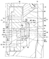
図1に示す燃料噴射弁1は、点火式の内燃機関であるガソリンエンジンに搭載されており、多気筒エンジンの各燃焼室へ直接燃料を噴射するものである。燃料噴射弁1へ供給される燃料は、図示しない燃料ポンプにより圧送され、燃料ポンプはエンジンの回転駆動力により駆動する。燃料噴射弁1は、ケース10、ノズルボデー20、弁体30、可動コア41、固定コア50,51、非磁性部材60、コイル70、配管接続部80等を備えて構成されている。
(1st Embodiment)
The fuel injection valve 1 shown in FIG. 1 is mounted on a gasoline engine, which is an ignition type internal combustion engine, and directly injects fuel into each combustion chamber of a multi-cylinder engine. Fuel supplied to the fuel injection valve 1 is pumped by a fuel pump (not shown), and the fuel pump is driven by the rotational driving force of the engine. The fuel injection valve 1 includes a case 10, a nozzle body 20, a valve body 30, a movable core 41, fixed cores 50 and 51, a non-magnetic member 60, a coil 70, a pipe connection portion 80, and the like.

ケース10は、金属製であり、コイル70の環状中心線Cが延びる方向(以下、軸線方向と記載)に延びる円筒形状である。なお、コイル70の環状中心線Cと、ケース10、ノズルボデー20、弁体30、可動コア41、固定コア50,51および非磁性部材60の中心軸線とは一致する。   The case 10 is made of metal and has a cylindrical shape extending in a direction in which the annular center line C of the coil 70 extends (hereinafter, referred to as an axial direction). The annular center line C of the coil 70 coincides with the center axes of the case 10, the nozzle body 20, the valve body 30, the movable core 41, the fixed cores 50 and 51, and the non-magnetic member 60.

ノズルボデー20は、金属製であり、ケース10内に挿入配置されてケース10と係合するボデー本体部21と、ボデー本体部21からケース10外部に延出するノズル部22とを有する。ボデー本体部21及びノズル部22は、いずれも軸線方向に延びる円筒形状であり、ノズル部22の先端には噴孔部材23が取り付けられている。   The nozzle body 20 is made of metal and has a body main body 21 inserted into the case 10 and engaged with the case 10, and a nozzle 22 extending from the body main body 21 to the outside of the case 10. Each of the body body 21 and the nozzle 22 has a cylindrical shape extending in the axial direction, and an injection hole member 23 is attached to a tip of the nozzle 22.

噴孔部材23は、金属製であり、ノズル部22に溶接で固定されている。噴孔部材23は軸線方向に延びる有底の円筒形状であり、噴孔部材23の先端には、燃料を噴射する噴孔23aが形成されている。噴孔部材23の内周面には、弁体30が離着座する着座面23sが形成されている。   The injection hole member 23 is made of metal, and is fixed to the nozzle portion 22 by welding. The injection hole member 23 has a cylindrical shape with a bottom extending in the axial direction, and an injection hole 23 a for injecting fuel is formed at the tip of the injection hole member 23. On the inner peripheral surface of the injection hole member 23, a seating surface 23s on which the valve body 30 is separated and seated is formed.

弁体30は、金属製であり、軸線方向に沿って延びる円柱形状である。弁体30は、軸線方向に移動可能な状態でノズルボデー20の内部に組み付けられており、弁体30の外周面30aとノズルボデー20の内周面20aとの間で、軸線方向に延びる環状の流通路が形成されている。この流通路を下流通路F30と称する。弁体30の噴孔23a側の端部には、着座面23sに離着座する、環状のシート面30sが形成されている。   The valve body 30 is made of metal and has a cylindrical shape extending along the axial direction. The valve body 30 is assembled inside the nozzle body 20 so as to be movable in the axial direction. An annular flow extending in the axial direction between the outer peripheral surface 30a of the valve body 30 and the inner peripheral surface 20a of the nozzle body 20. A road is formed. This flow passage is referred to as a downstream passage F30. An annular seat surface 30s is formed at the end of the valve body 30 on the side of the injection hole 23a, which seats on and separates from the seating surface 23s.

弁体30のうち噴孔23aの反対側(以下、反噴孔側と記載)の端部には、連結部材31が溶接等により固定して取り付けられている。さらに、連結部材31の反噴孔側端部には、オリフィス部材32および可動コア41が取り付けられている。   A connecting member 31 is fixedly attached by welding or the like to an end of the valve body 30 opposite to the injection hole 23a (hereinafter, referred to as an opposite injection hole side). Further, an orifice member 32 and a movable core 41 are attached to an end of the connecting member 31 opposite to the injection hole.

図2、図3に示すように、連結部材31は軸線方向に延びる円筒形状であり、円筒内部が燃料を流通させる流通路F23として機能する。オリフィス部材32は、連結部材31の円筒内周面に溶接等により固定され、可動コア41は、連結部材31の円筒外周面に溶接等により固定されている。連結部材31の反噴孔側端部には、径方向に拡大する拡径部31aが形成されている。拡径部31aの噴孔側端面が可動コア41と係合することで、連結部材31が可動コア41に対して噴孔側に抜け出ることを防止している。   As shown in FIGS. 2 and 3, the connecting member 31 has a cylindrical shape extending in the axial direction, and the inside of the cylinder functions as a flow passage F23 through which fuel flows. The orifice member 32 is fixed to the cylindrical inner peripheral surface of the connecting member 31 by welding or the like, and the movable core 41 is fixed to the cylindrical outer peripheral surface of the connecting member 31 by welding or the like. At the end of the connecting member 31 on the side opposite to the injection hole, an enlarged diameter portion 31a that expands in the radial direction is formed. By engaging the injection hole side end surface of the enlarged diameter portion 31 a with the movable core 41, the connection member 31 is prevented from coming off to the injection hole side with respect to the movable core 41.

オリフィス部材32は軸線方向に延びる円筒形状であり、円筒内部が燃料を流通させる流通路F21として機能する。オリフィス部材32の噴孔側端部には、流通路F21の通路面積を部分的に狭くして流量を絞る絞り部としてのオリフィス32aが形成されている。流通路F21のうちオリフィス32aにより絞られた部分を絞り流通路F22と呼ぶ。   The orifice member 32 has a cylindrical shape extending in the axial direction, and the inside of the cylinder functions as a flow passage F21 through which fuel flows. An orifice 32a is formed at the end of the orifice member 32 on the injection hole side as a throttle portion for reducing the flow area by partially reducing the passage area of the flow passage F21. The portion of the flow passage F21 narrowed by the orifice 32a is referred to as a throttle flow passage F22.

絞り流通路F22は弁体30の中心軸線上に位置する。絞り流通路F22の流路長さは絞り流通路F22の直径よりも短い。オリフィス部材32の反噴孔側端部には、径方向に拡大する拡径部32bが形成されている。拡径部32bの噴孔側端面が連結部材31と係合することで、オリフィス部材32が連結部材31に対して噴孔側に抜け出ることを防止している。   The throttle flow passage F22 is located on the central axis of the valve body 30. The flow path length of the throttle flow passage F22 is shorter than the diameter of the throttle flow passage F22. At the end of the orifice member 32 on the side opposite to the injection hole, an enlarged diameter portion 32b that expands in the radial direction is formed. The orifice member 32 is prevented from slipping out of the connecting member 31 toward the injection hole by engaging the nozzle-side end surface of the enlarged diameter portion 32b with the connecting member 31.

可動構造体Mは、移動部材35及び押付用弾性部材SP2を有している。移動部材35は、オリフィス部材32に対して軸線方向に相対移動可能な状態で、連結部材31の内部の流通路F23に配置されている。   The movable structure M has a moving member 35 and a pressing elastic member SP2. The moving member 35 is disposed in the flow passage F23 inside the connecting member 31 so as to be movable relative to the orifice member 32 in the axial direction.

移動部材35は、軸線方向に延びる金属製の円柱形状であり、オリフィス部材32の下流側に配置されている。移動部材35の円柱中心部分には軸線方向に貫通する貫通穴が形成されている。この貫通穴は、流通路Fの一部であり絞り流通路F22と連通し、絞り流通路F22よりも通路面積が小さいサブ絞り流通路38として機能する。移動部材35は、絞り流通路F22を覆うシール面36aが形成されたシール部36と、押付用弾性部材SP2と係合する係合部37とを有する。   The moving member 35 has a metal cylindrical shape extending in the axial direction, and is disposed downstream of the orifice member 32. A through hole penetrating in the axial direction is formed at the center of the cylinder of the moving member 35. This through hole is a part of the flow passage F, communicates with the throttle flow passage F22, and functions as a sub-throttle flow passage 38 having a smaller passage area than the throttle flow passage F22. The moving member 35 has a seal portion 36 formed with a seal surface 36a that covers the throttle flow passage F22, and an engaging portion 37 that engages with the pressing elastic member SP2.

係合部37はシール部36よりも小径であり、コイル形状の押付用弾性部材SP2が係合部37に嵌め込まれている。これにより、押付用弾性部材SP2の径方向への移動が係合部37で規制される。押付用弾性部材SP2の一端はシール部36の下端面に支持され、押付用弾性部材SP2の他端は連結部材31に支持される。押付用弾性部材SP2は、軸線方向に弾性変形して弾性力を移動部材35へ付与し、移動部材35のシール面36aは、オリフィス部材32の下端面に弾性力で押し付けられて密着する。   The engagement portion 37 has a smaller diameter than the seal portion 36, and the coil-shaped pressing elastic member SP <b> 2 is fitted into the engagement portion 37. Thereby, the movement of the pressing elastic member SP2 in the radial direction is restricted by the engagement portion 37. One end of the pressing elastic member SP2 is supported by the lower end surface of the seal portion 36, and the other end of the pressing elastic member SP2 is supported by the connecting member 31. The pressing elastic member SP2 elastically deforms in the axial direction to apply an elastic force to the moving member 35, and the sealing surface 36a of the moving member 35 is pressed against the lower end surface of the orifice member 32 by the elastic force and is brought into close contact therewith.

可動コア41は、金属製の円環状部材である。可動コア41は、可動内側部42及び可動外側部43を有しており、いずれも円環状になっている。可動内側部42は可動コア41の内周面を形成し、可動外側部43は可動内側部42の径方向外側に配置されている。可動コア41は、反噴孔側を向いた可動上面41aを有しており、可動上面41aは、可動コア41の上端面を形成している。可動上面41aには段差が形成されている。具体的には、可動外側部43は反噴孔側を向いた可動外側上面43aを有し、可動内側部42は反噴孔側を向いた可動内側上面42aを有しており、可動外側上面43aが可動内側上面42aよりも噴孔側にあることで、可動上面41aに段差が形成されている。可動内側上面42a及び可動外側上面43aは、いずれも軸線方向に直交している。   The movable core 41 is an annular member made of metal. The movable core 41 has a movable inner part 42 and a movable outer part 43, both of which are annular. The movable inner part 42 forms the inner peripheral surface of the movable core 41, and the movable outer part 43 is arranged radially outside the movable inner part 42. The movable core 41 has a movable upper surface 41a facing the injection hole side, and the movable upper surface 41a forms an upper end surface of the movable core 41. A step is formed on the movable upper surface 41a. Specifically, the movable outer portion 43 has a movable outer upper surface 43a facing the nozzle hole side, and the movable inner portion 42 has a movable inner upper surface 42a facing the nozzle hole side. The step 43a is formed on the movable upper surface 41a because the 43a is closer to the injection hole than the movable inner upper surface 42a. The movable inner upper surface 42a and the movable outer upper surface 43a are both orthogonal to the axial direction.

可動コア41は、噴孔側を向いた可動下面41bを有しており、この可動下面41bは、径方向において可動内側部42と可動外側部43とに跨った状態で、可動コア41において平坦な下端面を形成している。可動下面41bにおいては、可動内側部42と可動外側部43との境界部に段差が形成されていない。軸線方向においては、可動外側部43の高さ寸法が可動内側部42の高さ寸法より小さくなっており、可動コア41は、可動外側部43が可動内側部42から外周側に突出したような形状になっている。   The movable core 41 has a movable lower surface 41b facing the injection hole side, and the movable lower surface 41b is flat on the movable core 41 while straddling the movable inner portion 42 and the movable outer portion 43 in the radial direction. The lower end surface. In the movable lower surface 41b, no step is formed at the boundary between the movable inner portion 42 and the movable outer portion 43. In the axial direction, the height dimension of the movable outer part 43 is smaller than the height dimension of the movable inner part 42, and the movable core 41 is such that the movable outer part 43 protrudes outward from the movable inner part 42. It has a shape.

可動コア41は、連結部材31、弁体30、オリフィス部材32、および以下に説明する摺動部材33と一体となって軸線方向に移動する。これらの可動コア41、連結部材31、弁体30、オリフィス部材32および摺動部材33は、一体となって軸線方向に移動する可動構造体Mに相当する。   The movable core 41 moves in the axial direction integrally with the connecting member 31, the valve body 30, the orifice member 32, and the sliding member 33 described below. The movable core 41, the connecting member 31, the valve body 30, the orifice member 32, and the sliding member 33 correspond to a movable structure M that moves integrally in the axial direction.

摺動部材33は、可動コア41とは別体であるが、溶接等により可動コア41に固定されている。摺動部材33を可動コア41と別体にすることで、摺動部材33を可動コア41とは材質や材料が異なる構成を容易に実現できるようにしている。可動コア41には、摺動部材33に比べて高磁性の材料が用いられており、摺動部材33には、可動コア41に比べて耐摩耗性の高い材料が用いられている。   The sliding member 33 is separate from the movable core 41, but is fixed to the movable core 41 by welding or the like. By making the sliding member 33 separate from the movable core 41, the sliding member 33 can easily realize a configuration different in material or material from the movable core 41. The movable core 41 is made of a material having higher magnetism than the sliding member 33, and the sliding member 33 is made of a material having higher wear resistance than the movable core 41.

摺動部材33は円筒形状であり、摺動部材33の円筒外周面は、ノズルボデー20側の部材に対して摺動する摺動面33aとして機能する。摺動部材33の反噴孔側の面は、可動コア41の噴孔側の面に溶接等により接合されており、摺動部材33と可動コア41との間を燃料が通過しないようになっている。摺動部材33の反噴孔側端部には、径方向に縮小する縮径部33cが形成されている。ボデー本体部21には支持部材24が固定されており、支持部材24には、径方向に縮小する縮径部24aが形成されている。摺動部材33と支持部材24とは軸線方向において並べて配置されており、可動構造体Mの移動に伴って摺動部材33と支持部材24との離間距離は増減する。この離間距離は、弁体30が閉弁状態にある場合に最小になるが、この場合でも摺動部材33は支持部材24から反噴孔側に離間している。   The sliding member 33 has a cylindrical shape, and a cylindrical outer peripheral surface of the sliding member 33 functions as a sliding surface 33a that slides on a member on the nozzle body 20 side. The surface on the side opposite the injection hole of the sliding member 33 is joined to the surface on the injection hole side of the movable core 41 by welding or the like, so that fuel does not pass between the sliding member 33 and the movable core 41. ing. A reduced diameter portion 33c that is reduced in the radial direction is formed at the end of the sliding member 33 opposite the injection hole. A support member 24 is fixed to the body main body 21. The support member 24 has a reduced diameter portion 24a that is reduced in the radial direction. The sliding member 33 and the supporting member 24 are arranged side by side in the axial direction, and the distance between the sliding member 33 and the supporting member 24 increases or decreases as the movable structure M moves. This separation distance is minimized when the valve body 30 is in the valve-closed state, but in this case also, the sliding member 33 is separated from the support member 24 on the side opposite to the injection hole.

可動構造体Mには、ノズルボデー20に対して可動構造体Mを軸線方向に移動可能に摺動させつつ径方向に支持するガイド部が設けられている。ガイド部は、軸線方向の2箇所に設けられており、軸線方向のうち噴孔23aの側に位置するガイド部を噴孔側ガイド部30b(図1参照)と呼び、反噴孔側に位置するガイド部を反噴孔側ガイド部31bと呼ぶ。噴孔側ガイド部30bは、弁体30の外周面に形成され、噴孔部材23の内周面に摺動可能に支持される。反噴孔側ガイド部31bは、連結部材31の外周面に形成され、支持部材24の内周面に摺動可能に支持される。   The movable structure M is provided with a guide portion that supports the movable structure M in the radial direction while slidably moving the movable structure M in the axial direction with respect to the nozzle body 20. The guide portions are provided at two positions in the axial direction. The guide portion located on the side of the injection hole 23a in the axial direction is called the injection hole side guide portion 30b (see FIG. 1), and is located on the side opposite to the injection hole. The guide portion that performs this operation is referred to as a non-injection hole side guide portion 31b. The injection hole side guide portion 30 b is formed on the outer peripheral surface of the valve body 30, and is slidably supported on the inner peripheral surface of the injection hole member 23. The anti-injection hole side guide portion 31 b is formed on the outer peripheral surface of the connecting member 31 and is slidably supported on the inner peripheral surface of the support member 24.

固定コア50,51は、ケース10の内部に固定して配置されている。固定コア50,51は、軸線方向の周りに延びる環状の金属製である。第1固定コア50は、コイル70の内周側に設けられており、第1固定コア50の外周面とコイル70の内周面とが対向している。第1固定コア50は、噴孔側を向いた第1下面50aを有しており、この第1下面50aは、第1固定コア50の下端面を形成し、軸線方向に直交している。第1固定コア50は、可動コア41の反噴孔側に設けられており、第1下面50aは可動コア41の可動内側上面42aに対向している。また、第1固定コア50は、第1傾斜面50b及び第1外面50cを有している。第1傾斜面50bは、第1下面50aの外周側端部から反噴孔側に向けて斜めに延びている。第1外面50cは、第1固定コア50の外周面であり、第1傾斜面50bの反噴孔側の上端部から軸線方向に延びている。第1固定コア50は、第1下面50aと第1外面50cとの出隅部分が第1傾斜面50bにより面取りされたような形状になっている。   The fixed cores 50 and 51 are fixedly arranged inside the case 10. The fixed cores 50 and 51 are made of an annular metal extending around the axial direction. The first fixed core 50 is provided on the inner peripheral side of the coil 70, and the outer peripheral surface of the first fixed core 50 and the inner peripheral surface of the coil 70 face each other. The first fixed core 50 has a first lower surface 50a facing the injection hole side. The first lower surface 50a forms a lower end surface of the first fixed core 50 and is orthogonal to the axial direction. The first fixed core 50 is provided on the side opposite to the injection hole of the movable core 41, and the first lower surface 50 a faces the movable inner upper surface 42 a of the movable core 41. The first fixed core 50 has a first inclined surface 50b and a first outer surface 50c. The first inclined surface 50b extends obliquely from the outer peripheral end of the first lower surface 50a toward the side opposite to the injection hole. The first outer surface 50c is the outer peripheral surface of the first fixed core 50, and extends in the axial direction from the upper end of the first inclined surface 50b on the side opposite to the injection hole. The first fixed core 50 has a shape in which a protruding corner between the first lower surface 50a and the first outer surface 50c is chamfered by the first inclined surface 50b.

第2固定コア51は、コイル70の噴孔側に設けられており、全体として円環状になっている。第2内側部52及び第2外側部53を有しており、いずれも円環状になっている。第2外側部53は第2固定コア51の外周面を形成しており、第2内側部52は第2外側部53の内周側に配置されている。第2固定コア51は噴孔側を向いた第2下面51aを有しており、第2下面51aは、第2固定コア51の下端面を形成し、軸線方向に直交している。第2下面51aには段差が形成されている。具体的には、第2内側部52は噴孔側を向いた第2内側下面52aを有し、第2外側部53は噴孔側を向いた第2外側下面53aを有しており、第2内側下面52aが第2外側下面53aよりも反噴孔側にあることで、第2下面51aに段差が形成されている。軸線方向においては、第2内側部52の高さ寸法が第2外側部53の高さ寸法より小さくなっており、第2固定コア51は、第2内側部52が第2外側部53から内周側に突出したような形状になっている。   The second fixed core 51 is provided on the injection hole side of the coil 70, and has an annular shape as a whole. It has a second inner part 52 and a second outer part 53, both of which are annular. The second outer portion 53 forms the outer peripheral surface of the second fixed core 51, and the second inner portion 52 is disposed on the inner peripheral side of the second outer portion 53. The second fixed core 51 has a second lower surface 51a facing the injection hole side, and the second lower surface 51a forms a lower end surface of the second fixed core 51 and is orthogonal to the axial direction. A step is formed on the second lower surface 51a. Specifically, the second inner portion 52 has a second inner lower surface 52a facing the injection hole side, and the second outer portion 53 has a second outer lower surface 53a facing the injection hole side. Since the second inner lower surface 52a is closer to the injection hole than the second outer lower surface 53a, a step is formed on the second lower surface 51a. In the axial direction, the height of the second inner portion 52 is smaller than the height of the second outer portion 53, and the second fixed core 51 is configured such that the second inner portion 52 is inward from the second outer portion 53. It has a shape that protrudes to the peripheral side.

第2固定コア51の第2内側部52は、可動コア41の可動外側部43よりも反噴孔側に配置されており、これら第2内側部52と可動外側部43とは軸線方向に並んでいる。この場合、軸線方向において第2内側下面52aと可動外側上面43aとが対向している。   The second inner portion 52 of the second fixed core 51 is located closer to the injection hole side than the movable outer portion 43 of the movable core 41, and the second inner portion 52 and the movable outer portion 43 are arranged in the axial direction. In. In this case, the second inner lower surface 52a and the movable outer upper surface 43a face each other in the axial direction.

第2固定コア51においては、第2外側部53がボデー本体部21の反噴孔側に設けられている。ここで、ボデー本体部21は、径方向外側の端部から反噴孔側に向けて延びた円環状の外側延出部211を有している。外側延出部211は、ボデー本体部21の上端面において径方向内側の端部から離間していることで、ボデー本体部21の上端面に段差を形成している。ボデー本体部21は、本体内側上面21a、本体外側上面21b、本体外側内面21c、本体内側内面21dを有しており、本体内側上面21a及び本体外側上面21bは反噴孔側を向き、本体外側内面21c及び本体内側内面21dは径方向内側を向いている。本体外側上面21bは外側延出部211の上端面であり、本体外側内面21cは外側延出部211の内周面である。本体内側内面21dは、本体内側上面21aの径方向内側の端部から噴孔側に向けて延びており、ボデー本体部21の内周面である。本体内側上面21aは、ボデー本体部21の上端面のうち本体外側内面21cよりも径方向内側の部分である。本体内側上面21a及び本体外側上面21bは軸線方向に直交しており、本体外側内面21cは軸線方向に平行に延びている。   In the second fixed core 51, the second outer portion 53 is provided on the body main body portion 21 on the side opposite to the injection hole. Here, the body main body 21 has an annular outer extension 211 extending from the radially outer end toward the injection hole side. The outer extension portion 211 forms a step in the upper end surface of the body main body 21 by being separated from the inner end in the radial direction on the upper end surface of the body main body 21. The body main body portion 21 has a main body inner upper surface 21a, a main body outer upper surface 21b, a main body outer inner surface 21c, and a main body inner inner surface 21d. The main body inner upper surface 21a and the main body outer upper surface 21b face the injection hole side, and the main body outer surface 21b. The inner surface 21c and the inner body inner surface 21d face radially inward. The main body outer upper surface 21b is the upper end surface of the outer extending portion 211, and the main body outer inner surface 21c is the inner peripheral surface of the outer extending portion 211. The main body inner inner surface 21 d extends from the radially inner end of the main body inner upper surface 21 a toward the injection hole, and is the inner peripheral surface of the body main body 21. The main body inner upper surface 21a is a portion of the upper end surface of the body main body 21 that is radially inner than the main body outer inner surface 21c. The main body inner upper surface 21a and the main body outer upper surface 21b are orthogonal to the axial direction, and the main body outer inner surface 21c extends parallel to the axial direction.

第2固定コア51においては、第2外側下面53aが本体外側上面21bに重ねられており、この重ねられた部分において第2固定コア51とボデー本体部21とがレーザー溶接等の溶接により接合されている。溶接が行われる前の状態においては、第2外側下面53a及び本体外側上面21bが第2固定コア51とボデー本体部21との境界部である固定境界部Qに含まれている。径方向において、第2外側下面53aの幅寸法と本体外側上面21bの幅寸法とは同じになっており、これら第2外側下面53aと本体外側上面21bとはそれぞれの全体が互いに重なっている。第2外側部53の外周面及びボデー本体部21の外周面はそれぞれケース10の内周面に重なっている。   In the second fixed core 51, the second outer lower surface 53a is overlapped with the main body outer upper surface 21b, and the second fixed core 51 and the body main body 21 are joined at the overlapped portion by welding such as laser welding. ing. In a state before welding is performed, the second outer lower surface 53a and the main body outer upper surface 21b are included in a fixed boundary portion Q that is a boundary portion between the second fixed core 51 and the body main body portion 21. In the radial direction, the width dimension of the second outer lower surface 53a and the width dimension of the main body outer upper surface 21b are the same, and the second outer lower surface 53a and the main body outer upper surface 21b entirely overlap each other. The outer peripheral surface of the second outer portion 53 and the outer peripheral surface of the body main body 21 overlap the inner peripheral surface of the case 10, respectively.

第2固定コア51は、第2上面51b及び第2傾斜面51cを有している。第2傾斜面51cは、第2内側部52の内周面である第2内側内面52bから反噴孔側に向けて斜めに延びており、第2上面51bは、第2傾斜面51cの上端部から径方向に延びている。この場合、第2上面51b及び第2傾斜面51cは、第2固定コア51の上端面を形成している。第2傾斜面51cは、径方向において第2内側部52と第2外側部53とに跨った状態になっている。第2固定コア51は、第2上面51bと外周面との出隅部分が第2傾斜面51cにより面取りされたような形状になっている。   The second fixed core 51 has a second upper surface 51b and a second inclined surface 51c. The second inclined surface 51c extends obliquely from the second inner inner surface 52b, which is the inner peripheral surface of the second inner portion 52, toward the injection hole side, and the second upper surface 51b is at the upper end of the second inclined surface 51c. Extending radially from the section. In this case, the second upper surface 51b and the second inclined surface 51c form the upper end surface of the second fixed core 51. The second inclined surface 51c is in a state of straddling the second inner portion 52 and the second outer portion 53 in the radial direction. The second fixed core 51 has such a shape that a protruding corner portion between the second upper surface 51b and the outer peripheral surface is chamfered by the second inclined surface 51c.

非磁性部材60は、軸線方向の周りに延びる環状の金属製部材であり、第1固定コア50と第2固定コア51との間に設けられている。非磁性部材60は、固定コア50,51や可動コア41よりも磁性が弱く、例えば非磁性体により形成されている。この非磁性部材60と同様に、ボデー本体部21も、固定コア50,51や可動コア41に比べて磁性が弱く、例えば非磁性体により形成されている。一方、固定コア50,51及び可動コア41は磁性を有しており、例えば強磁性体により形成されている。   The non-magnetic member 60 is an annular metal member extending around the axial direction, and is provided between the first fixed core 50 and the second fixed core 51. The non-magnetic member 60 has lower magnetism than the fixed cores 50 and 51 and the movable core 41, and is formed of, for example, a non-magnetic material. Similarly to the non-magnetic member 60, the body main body 21 is also weaker in magnetism than the fixed cores 50 and 51 and the movable core 41, and is formed of, for example, a non-magnetic material. On the other hand, the fixed cores 50 and 51 and the movable core 41 have magnetism and are formed of, for example, a ferromagnetic material.

なお、固定コア50,51及び可動コア41を、磁束の通路になりやすい磁束通路部材と称し、非磁性部材60及びボデー本体部21を、磁束の通路になりにくい磁束規制部材と称することができる。特に、後述するように、非磁性部材60は、磁束が可動コア41を通らずに固定コア50,51を磁気的に短絡して通ることを規制する機能を有しており、非磁性部材60を短絡規制部材と称することもできる。また、非磁性部材60が短絡規制部を構成していることにもなる。ノズルボデー20については、ボデー本体部21及びノズル部22が金属材料により一体成型されていることで、ボデー本体部21及びノズル部22の両方が磁性の弱くなっている。   In addition, the fixed cores 50 and 51 and the movable core 41 can be referred to as a magnetic flux passage member that easily becomes a magnetic flux passage, and the nonmagnetic member 60 and the body main body 21 can be referred to as a magnetic flux regulating member that hardly becomes a magnetic flux passage. . In particular, as described later, the non-magnetic member 60 has a function of restricting the magnetic flux from passing through the fixed cores 50 and 51 by magnetic short-circuit without passing through the movable core 41. May be referred to as a short-circuit restriction member. In addition, the non-magnetic member 60 constitutes a short-circuit restriction part. Regarding the nozzle body 20, both the body body 21 and the nozzle 22 have weak magnetism because the body body 21 and the nozzle 22 are integrally formed of a metal material.

非磁性部材60は、上傾斜面60a及び下傾斜面60bを有している。上傾斜面60aは、第1固定コア50の第1傾斜面50bに重ねられており、これら上傾斜面60aと第1傾斜面50bとは溶接により接合されている。下傾斜面60bは、第2固定コア51の第2傾斜面51cに重ねられており、これら下傾斜面60bと第2傾斜面51cとは溶接により接合されている。第1傾斜面50bと第2傾斜面51cとは、それぞれの少なくとも一部が軸線方向に並んでおり、非磁性部材60は、少なくとも軸線方向においてこれら傾斜面50b,51cの間に入り込んだ状態になっている。   The non-magnetic member 60 has an upper inclined surface 60a and a lower inclined surface 60b. The upper inclined surface 60a is overlapped with the first inclined surface 50b of the first fixed core 50, and the upper inclined surface 60a and the first inclined surface 50b are joined by welding. The lower inclined surface 60b is overlapped with the second inclined surface 51c of the second fixed core 51, and the lower inclined surface 60b and the second inclined surface 51c are joined by welding. At least a part of each of the first inclined surface 50b and the second inclined surface 51c is arranged in the axial direction, and the non-magnetic member 60 is in a state of entering at least between the inclined surfaces 50b and 51c in the axial direction. Has become.

第1固定コア50の内周面には、円筒形状かつ金属製のストッパ55が固定されている。ストッパ55は、可動構造体Mの連結部材31と当接することで可動構造体Mが反噴孔側へ移動することを規制する部材であり、ストッパ55の下端面が連結部材31の拡径部31aの上端面に当接することで、可動構造体Mの移動が規制される。ストッパ55は、第1固定コア50よりも噴孔側に突出している。このため、ストッパ55により可動構造体Mの移動が規制された状態でも、固定コア50,51と可動コア41との間に所定のギャップが形成されている。このギャップは、第1下面50aと可動内側上面42aとの間や、第2内側下面52aと可動外側上面43aとの間に形成されている。図3等では、これらギャップを明確に図示するために、第1下面50aと可動内側上面42aとの離間距離や、第2内側下面52aと可動外側上面43aとの離間距離を実際よりも大きめに図示している。   A cylindrical stopper 55 made of metal is fixed to the inner peripheral surface of the first fixed core 50. The stopper 55 is a member that restricts the movable structure M from moving toward the non-injection hole side by contacting the connecting member 31 of the movable structure M. The movement of the movable structure M is restricted by contacting the upper end surface of the movable structure 31a. The stopper 55 protrudes more toward the injection hole than the first fixed core 50. Therefore, a predetermined gap is formed between the fixed cores 50 and 51 and the movable core 41 even when the movement of the movable structure M is restricted by the stopper 55. This gap is formed between the first lower surface 50a and the movable inner upper surface 42a and between the second inner lower surface 52a and the movable outer upper surface 43a. In FIG. 3 and the like, in order to clearly illustrate these gaps, the distance between the first lower surface 50a and the movable inner upper surface 42a and the distance between the second inner lower surface 52a and the movable outer upper surface 43a are made larger than actual. It is illustrated.

非磁性部材60および固定コア50の径方向外側には、コイル70が配置されている。コイル70は、樹脂製のボビン71に巻き回されている。ボビン71は、軸線方向を中心とした円筒形状である。したがって、コイル70は、軸線方向の周りに延びる環状に配置されることになる。ボビン71は、第1固定コア50及び非磁性部材60に当接している。ボビン71の外周側の開口部、上端面及び下端面は、樹脂製のカバー72で覆われている。   A coil 70 is arranged radially outside the non-magnetic member 60 and the fixed core 50. The coil 70 is wound around a bobbin 71 made of resin. The bobbin 71 has a cylindrical shape centered on the axial direction. Therefore, the coil 70 is arranged in an annular shape extending around the axial direction. The bobbin 71 is in contact with the first fixed core 50 and the non-magnetic member 60. The opening, upper end surface and lower end surface on the outer peripheral side of the bobbin 71 are covered with a resin cover 72.

カバー72とケース10との間には、ヨーク75が設けられている。ヨーク75は、第2固定コア51の反噴孔側に配置されており、第2固定コア51の第2上面51bに当接している。ヨーク75は、固定コア50,51や可動コア41と同様に磁性を有しており、例えば強磁性体により形成されている。なお、固定コア50,51や可動コア41は、流通路を形成するなど燃料に触れる位置に配置されており、耐油性を有している。これに対して、ヨーク75は、流通路を形成していないなど燃料に触れない位置に配置されており、耐油性を有していない。このため、ヨーク75は、固定コア50,51や可動コア41よりも更に高い磁性を有している。   A yoke 75 is provided between the cover 72 and the case 10. The yoke 75 is arranged on the side opposite to the injection hole of the second fixed core 51, and is in contact with the second upper surface 51 b of the second fixed core 51. The yoke 75 has magnetism similarly to the fixed cores 50 and 51 and the movable core 41, and is formed of, for example, a ferromagnetic material. Note that the fixed cores 50 and 51 and the movable core 41 are arranged at positions where they come into contact with fuel, such as forming a flow passage, and have oil resistance. On the other hand, the yoke 75 is disposed at a position where the yoke 75 does not come into contact with the fuel, for example, does not have a flow passage, and does not have oil resistance. Therefore, the yoke 75 has higher magnetism than the fixed cores 50 and 51 and the movable core 41.

本実施形態では、第2固定コア51とボデー本体部21との固定境界部Qを覆う覆い体90が、第2固定コア51及びボデー本体部21の内周側に設けられている。覆い体90は、環状であり、第2固定コア51の周方向において固定境界部Qの全体を覆っている。覆い体90は、固定境界部Qを軸線方向に跨いだ状態で、第2固定コア51及びボデー本体部21から径方向内側に突出している。ここで、ボデー本体部21は本体切欠部N21を有し、第2固定コア51は第2切欠部N51を有しており、覆い体90は、これら切欠部N21,N51に入り込んだ状態になっている。   In the present embodiment, a cover 90 that covers a fixed boundary portion Q between the second fixed core 51 and the body main body 21 is provided on the inner peripheral side of the second fixed core 51 and the body main body 21. The cover body 90 is annular and covers the entire fixed boundary portion Q in the circumferential direction of the second fixed core 51. The cover 90 protrudes radially inward from the second fixed core 51 and the body main body 21 while straddling the fixed boundary portion Q in the axial direction. Here, the body main body 21 has a main body cutout portion N21, the second fixed core 51 has a second cutout portion N51, and the cover body 90 is in a state of being inserted into these cutout portions N21 and N51. ing.

ボデー本体部21においては、本体切欠部N21が本体外側内面21c及び本体内側上面21aにより形成されている。本体切欠部N21は、軸線方向において噴孔側に開放されているとともに、径方向内側に開放されている。本体切欠部N21は、本体外側内面21cと本体内側上面21aとを接続する切欠傾斜面N21aを有しており、この切欠傾斜面N21aにより入隅部分が面取りされたような形状になっている。   In the body main body 21, the main body cutout portion N21 is formed by the main body outer inner surface 21c and the main body inner upper surface 21a. The main body cutout portion N21 is open to the injection hole side in the axial direction and is opened radially inward. The main body cutout portion N21 has a cutout inclined surface N21a that connects the main body outer inner surface 21c and the main body inner upper surface 21a, and has a shape in which an inner corner portion is chamfered by the cutout inclined surface N21a.

第2固定コア51においては、第2切欠部N51が第2内側下面52a及び第2外側内面53bにより形成されている。第2外側内面53bは、径方向内側を向いた状態で軸線方向に延びており、第2外側部53の内周面を形成している。第2切欠部N51は、第2固定コア51の第2下面51aの段差により形成されており、軸線方向において反噴孔側に開放されているとともに、径方向内側に開放されている。第2切欠部N51は、第2内側下面52aと第2外側内面53bとを接続する切欠傾斜面N51aを有しており、この切欠傾斜面N51aにより入隅部分が面取りされたような形状になっている。   In the second fixed core 51, the second cutout portion N51 is formed by the second inner lower surface 52a and the second outer inner surface 53b. The second outer inner surface 53b extends in the axial direction in a state facing inward in the radial direction, and forms an inner peripheral surface of the second outer portion 53. The second cutout portion N51 is formed by a step of the second lower surface 51a of the second fixed core 51, and is open to the side opposite to the injection hole in the axial direction and to the inside in the radial direction. The second cutout portion N51 has a cutout inclined surface N51a that connects the second inner lower surface 52a and the second outer inner surface 53b, and has a shape in which a corner portion is chamfered by the cutout inclined surface N51a. ing.

本体切欠部N21と第2切欠部N51とは軸線方向に連通されており、覆い体90は、これら切欠部N21,N51において第2内側下面52aと本体内側上面21aとの間に配置されている。ボデー本体部21の本体外側内面21cと第2固定コア51の第2外側内面53bとは、軸線方向において同一平面を形成している。覆い体90の外周面である覆い外面90aは、固定境界部Qを内側から覆った状態で本体外側内面21c及び第2外側内面53bの両方に重ねられている。ただし、覆い外面90aは、切欠傾斜面N21a,N51aには重なっていない。   The main body cutout portion N21 and the second cutout portion N51 communicate with each other in the axial direction, and the cover body 90 is disposed between the second inner lower surface 52a and the main body inner upper surface 21a at these cutout portions N21 and N51. . The outer body inner surface 21c of the body main body 21 and the second outer inner surface 53b of the second fixed core 51 form the same plane in the axial direction. The outer cover surface 90a, which is the outer peripheral surface of the cover body 90, is overlaid on both the main body outer inner surface 21c and the second outer inner surface 53b while covering the fixed boundary portion Q from the inside. However, the cover outer surface 90a does not overlap with the notched inclined surfaces N21a and N51a.

覆い体90は、覆い内側部92及び覆い外側部91を有している。覆い外側部91は覆い外面90aを形成しており、覆い内側部92は覆い外側部91の径方向内側に配置されている。覆い内側部92の高さ寸法H1は、覆い外側部H2の高さ寸法より小さくなっている(図4参照)。覆い体90は、反噴孔側を向いた覆い上面90bと、噴孔側を向いた覆い下面90cとを有している。これら覆い上面90bと覆い下面90cとは同じ面積になっている。   The cover body 90 has a cover inner portion 92 and a cover outer portion 91. The cover outer portion 91 forms a cover outer surface 90a, and the cover inner portion 92 is arranged radially inside the cover outer portion 91. The height dimension H1 of the cover inner part 92 is smaller than the height dimension of the cover outer part H2 (see FIG. 4). The cover body 90 has a cover upper surface 90b facing the nozzle hole side and a cover lower surface 90c facing the nozzle hole side. The covering upper surface 90b and the covering lower surface 90c have the same area.

覆い上面90bには、覆い内側部92の反噴孔側の上端面が覆い外側部91の反噴孔側の上端面より噴孔側に配置されていることで段差が形成されている。覆い下面90cは、覆い体90の噴孔側の平坦な下端面を形成しており、覆い下面90cにおいては、覆い内側部92と覆い外側部91との境界部に段差が形成されていない。   A step is formed on the upper surface 90b of the cover by disposing the upper end surface of the inner cover portion 92 on the side opposite to the injection hole from the upper end surface of the outer cover portion 91 on the side opposite to the injection hole. The covering lower surface 90c forms a flat lower end surface on the injection hole side of the covering body 90. In the covering lower surface 90c, no step is formed at the boundary between the covering inner portion 92 and the covering outer portion 91.

覆い体90においては、覆い上面90bにある段差により覆い切欠部N90が形成されている。覆い切欠部N90には、可動コア41の噴孔側であって外周側の出隅部分が入り込んでいる。この場合、覆い外側部91の反噴孔側の端部は、径方向において可動外側部と第2外側部53との間に配置されている。また、覆い内側部92は、軸線方向において第2外側部53の噴孔側に配置されている。   In the cover body 90, a cover notch N90 is formed by a step on the cover upper surface 90b. An outer corner on the side of the injection hole of the movable core 41 on the outer peripheral side enters the cover notch N90. In this case, the end on the side opposite to the injection hole of the outer cover portion 91 is disposed between the movable outer portion and the second outer portion 53 in the radial direction. The inner cover portion 92 is arranged on the injection hole side of the second outer portion 53 in the axial direction.

覆い体90においては、覆い上面90bが可動コア41の可動下面41b及び第2固定コア51の第2内側下面52aから噴孔側に離間しているとともに、覆い下面90cがボデー本体部21の本体内側上面21aから反噴孔側に離間している。覆い外側部91は、径方向において第2外側部53と可動外側部43との間に入り込んでおり、覆い内側部92は、軸線方向において可動コア41と本体内側上面21aとの間に入り込んでいる。   In the cover body 90, the cover upper surface 90 b is separated from the movable lower surface 41 b of the movable core 41 and the second inner lower surface 52 a of the second fixed core 51 toward the injection hole side, and the cover lower surface 90 c is the main body of the body body 21. It is separated from the inner upper surface 21a on the side opposite to the injection hole. The outer cover portion 91 is inserted between the second outer portion 53 and the movable outer portion 43 in the radial direction, and the inner cover portion 92 is inserted between the movable core 41 and the main body upper surface 21a in the axial direction. I have.

図3に示すように、軸線方向において、覆い上面90bと第2内側下面52aとの離間距離H1aと、覆い下面90cと本体内側上面21aとの離間距離H1bとが同じになっている。また、軸線方向において、固定境界部Qと第2内側下面52aとの離間距離H2aと、固定境界部Qと本体内側上面21aとの離間距離H2bとが同じになっている。これらの場合、軸線方向において、覆い外側部91及び固定境界部Qが第2内側下面52aと本体内側上面21aとの中央位置に配置されていることになる。   As shown in FIG. 3, the distance H1a between the cover upper surface 90b and the second inner lower surface 52a and the distance H1b between the cover lower surface 90c and the main body inner upper surface 21a are the same in the axial direction. In the axial direction, the distance H2a between the fixed boundary portion Q and the second inner lower surface 52a is the same as the distance H2b between the fixed boundary portion Q and the main body inner upper surface 21a. In these cases, the outer cover portion 91 and the fixed boundary portion Q are arranged at the center position between the second inner lower surface 52a and the main body inner upper surface 21a in the axial direction.

図2、図3において、軸線方向において覆い内側部92と可動コア41との離間距離は、可動構造体Mの移動に伴って増減するが、弁体30が着座面23sに着座することで、これら覆い内側部92と可動コア41とは接触しないようになっている。本実施形態では、覆い上面90bと可動コア41及び第2固定コア51との間の空間を覆い上室S1と称し、覆い下面90cとボデー本体部21との間の空間を覆い下室S2と称する。これら覆い上室S1及び覆い下室S2は、覆い体90が本体切欠部N21及び第2切欠部N51の内部に入り込んだ状態になっていることで形成されている。覆い上室S1は、後述する流通路F26sに含まれており、覆い下室S2は、後述する流通路F31に含まれている。   2 and 3, the separation distance between the covering inner portion 92 and the movable core 41 in the axial direction increases and decreases with the movement of the movable structure M, but when the valve body 30 is seated on the seating surface 23s, The inner cover portion 92 and the movable core 41 do not come into contact with each other. In the present embodiment, the space between the cover upper surface 90b and the movable core 41 and the second fixed core 51 is referred to as a cover upper chamber S1, and the space between the cover lower surface 90c and the body main body 21 is covered and the lower chamber S2 is formed. Name. The upper cover chamber S1 and the lower cover chamber S2 are formed by the cover body 90 having entered the insides of the main body cutout portion N21 and the second cutout portion N51. The cover upper chamber S1 is included in a flow passage F26s described later, and the cover lower chamber S2 is included in a flow passage F31 described later.

覆い体90は、覆い部材93及び対向部材94により形成されている。これら覆い部材93及び対向部材94は、いずれも金属製の円環状部材であり、覆い部材93の内周側に対向部材94が設けられている。対向部材94は覆い部材93の内周面に嵌合された状態になっており、これら対向部材94と覆い部材93とは、互いの境界部において溶接等により接合されている。覆い部材93は、覆い外側部91に含まれる外周面寄りの部分と、覆い内側部92に含まれる内周面寄りの部分とを有している。これに対して、対向部材94は、その全体が覆い内側部92に含まれている。対向部材94は、対向部を構成しており、覆い部材93により支持されている。   The cover body 90 is formed by a cover member 93 and a facing member 94. Each of the covering member 93 and the facing member 94 is an annular member made of metal, and the facing member 94 is provided on the inner peripheral side of the covering member 93. The facing member 94 is fitted on the inner peripheral surface of the covering member 93, and the facing member 94 and the covering member 93 are joined to each other at a boundary portion by welding or the like. The cover member 93 has a portion closer to the outer peripheral surface included in the cover outer portion 91 and a portion closer to the inner peripheral surface included in the cover inner portion 92. On the other hand, the opposing member 94 is entirely included in the covering inner portion 92. The facing member 94 forms a facing portion and is supported by the cover member 93.

対向部材94は、対向内面94aを有しており、径方向において摺動部材33の外周側に配置されている。対向内面94aは、径方向において摺動部材33の摺動面33aに対向しており、摺動部材33の摺動面33aが対向内面94aに対して摺動する。この場合、上述した、摺動面33aを摺動させるノズルボデー20側の部材が、対向部材94になっている。対向内面94aは、対向部材94の内周面であり、軸線方向において、対向内面94aの高さ寸法は摺動面33aの高さ寸法より小さくなっている。対向内面94a及び摺動面33aは、いずれも軸線方向に平行に延びている。摺動面33aの直径は、対向内面94aの直径よりも僅かに小さくなっている。つまり、摺動部材33の摺動方向に直交する方向における摺動面33aの位置は、対向内面94aの最外周位置よりも内側、つまり環状中心線Cの側に位置する。   The facing member 94 has a facing inner surface 94a, and is arranged on the outer peripheral side of the sliding member 33 in the radial direction. The opposed inner surface 94a is radially opposed to the sliding surface 33a of the sliding member 33, and the sliding surface 33a of the sliding member 33 slides on the opposed inner surface 94a. In this case, the above-described member on the nozzle body 20 side that slides on the sliding surface 33a is the facing member 94. The opposing inner surface 94a is the inner peripheral surface of the opposing member 94, and the height of the opposing inner surface 94a is smaller than the height of the sliding surface 33a in the axial direction. Both the opposing inner surface 94a and the sliding surface 33a extend parallel to the axial direction. The diameter of the sliding surface 33a is slightly smaller than the diameter of the opposed inner surface 94a. That is, the position of the sliding surface 33a in the direction orthogonal to the sliding direction of the sliding member 33 is located inside the outermost peripheral position of the opposed inner surface 94a, that is, on the side of the annular center line C.

対向部材94は、摺動部材33がこの対向部材94に摺動することで可動構造体Mの移動方向を案内するガイド部としての機能も発揮することになる。この場合、対向内面94aを案内面やガイド面と称することもできる。また、対向部材94が案内部を構成している。   The opposing member 94 also exerts a function as a guide section for guiding the moving direction of the movable structure M when the sliding member 33 slides on the opposing member 94. In this case, the facing inner surface 94a may be referred to as a guide surface or a guide surface. Further, the facing member 94 constitutes a guide portion.

覆い部材93及び対向部材94は、非磁性部材60やボデー本体部21と同様に、固定コア50,51や可動コア41に比べて磁性が弱く、例えば非磁性体により形成されている。このため、覆い部材93及び対向部材94は、磁束の通路になりにくくなっている。ただし、対向部材94は、摺動部材33の摺動が行われても対向内面94aの摩耗や変形が生じにくいように、硬度や強度の高い材料を用いて形成されることが好ましい。本実施形態では、対向部材94の材料について硬度や強度の高さを優先しており、覆い部材93や非磁性部材60、ボデー本体部21に比べて対向部材94の磁性が強くなっている。この場合、対向部材94は、覆い部材93等に比べると磁束の通路になりやすくなってしまっているが、それでも、対向部材94の磁性は、固定コア50,51や可動コア41の磁性に比べて弱くなっており、固定コア50,51等に比べると磁束の通路になりにくい。   The covering member 93 and the opposing member 94 have lower magnetism than the fixed cores 50 and 51 and the movable core 41, like the nonmagnetic member 60 and the body main body 21, and are formed of, for example, a nonmagnetic material. For this reason, the covering member 93 and the opposing member 94 are less likely to form a magnetic flux path. However, the facing member 94 is preferably formed of a material having high hardness and strength so that the facing inner surface 94a is hardly worn or deformed even when the sliding member 33 slides. In the present embodiment, priority is given to the hardness and strength of the material of the facing member 94, and the facing member 94 is stronger in magnetism than the covering member 93, the non-magnetic member 60, and the body main body 21. In this case, the opposing member 94 is more likely to serve as a magnetic flux path than the covering member 93 or the like, but the magnetism of the opposing member 94 is still smaller than the magnetism of the fixed cores 50 and 51 and the movable core 41. And is less likely to be a magnetic flux path as compared with the fixed cores 50, 51 and the like.

上述したように、固定境界部Qは、第2固定コア51とボデー本体部21とが溶接された部分に含まれており、この部分を溶接部96と称する。溶接部96は、径方向において固定境界部Qの外側端部から所定の深さの範囲にかけての部分に配置されており、この溶接部96には、第2固定コア51及びボデー本体部21の一部に加えて、覆い体90の一部も含まれている。覆い体90については、覆い部材93のうち覆い外側部91を形成する部分が溶接部96に含まれている。径方向において溶接部96の奥行き寸法は、覆い部材93の一部を含んでいる分だけ固定境界部Qの幅寸法よりも大きくなっている。溶接部96は、第2固定コア51、ボデー本体部21及び覆い部材93のうち、加熱されることで溶融して混じり合った後に冷えて固化した状態の部分である。溶接部96においては、第2固定コア51、ボデー本体部21及び覆い部材93という3つの部材が接合されている。   As described above, the fixed boundary portion Q is included in a portion where the second fixed core 51 and the body main portion 21 are welded, and this portion is referred to as a welded portion 96. The welded portion 96 is disposed at a portion extending from the outer end of the fixed boundary portion Q to a range of a predetermined depth in the radial direction, and the welded portion 96 includes the second fixed core 51 and the body main body 21. In addition to a portion, a portion of the cover 90 is also included. In the cover 90, a portion of the cover member 93 that forms the cover outer portion 91 is included in the welded portion 96. The depth dimension of the welded portion 96 in the radial direction is larger than the width dimension of the fixed boundary portion Q by an amount including a part of the covering member 93. The welded portion 96 is a portion of the second fixed core 51, the body main body portion 21 and the cover member 93 that is melted and mixed by being heated, then cooled and solidified. In the welded portion 96, three members, that is, the second fixed core 51, the body main body 21, and the cover member 93 are joined.

溶接部96については、図3に網点で図示し、この図3においては固定境界部Qを仮想線で図示している。その一方で、図3以外の図2等では、溶接部96の図示を省略しているが、実際には、図3に示すように、第2固定コア51、ボデー本体部21及び覆い部材93の各一部と固定境界部Qとは溶接部96により消失している。このため、覆い体90は、実際には、固定境界部Qではなく溶接部96を径方向内側から覆うことになるが、本実施形態では、覆い体90が溶接部96を覆うことと、覆い体90が固定境界部Qを覆うこととを同義として記載している。   The welded portion 96 is shown by a halftone dot in FIG. 3, and the fixed boundary portion Q is shown by an imaginary line in FIG. On the other hand, in FIG. 2 and the like other than FIG. 3, the illustration of the welded portion 96 is omitted, but actually, as shown in FIG. 3, the second fixed core 51, the body main body 21, and the cover member 93 are provided. And the fixed boundary portion Q has disappeared due to the welded portion 96. For this reason, the cover 90 actually covers the welded portion 96 from the radially inner side instead of the fixed boundary portion Q, but in the present embodiment, the cover 90 covers the welded portion 96, The description that the body 90 covers the fixed boundary portion Q is synonymous.

図1の説明に戻り、第1固定コア50の反噴孔側には、燃料の流入口80aを形成して外部の配管と接続される配管接続部80が配置されている。配管接続部80は金属製であり、固定コア50と一体の金属部材で形成されている。高圧ポンプで加圧された燃料は、流入口80aから燃料噴射弁1へ供給される。配管接続部80の内部には、軸線方向に延びる燃料の流通路F11が形成されており、その流通路F11には圧入部材81が圧入固定されている。   Returning to the description of FIG. 1, on the side opposite to the injection hole of the first fixed core 50, a pipe connection part 80 that forms a fuel inlet 80 a and is connected to an external pipe is disposed. The pipe connection part 80 is made of metal, and is formed of a metal member integrated with the fixed core 50. The fuel pressurized by the high-pressure pump is supplied to the fuel injection valve 1 from the inlet 80a. A fuel flow passage F11 extending in the axial direction is formed inside the pipe connection portion 80, and a press-fitting member 81 is press-fitted and fixed in the flow passage F11.

圧入部材81の噴孔側には、弾性部材SP1が配置されている。弾性部材SP1の一端は圧入部材81に支持され、弾性部材SP1の他端はオリフィス部材32の拡径部32bに支持される。したがって、圧入部材81の圧入量、つまり軸線方向における固定位置に応じて、弁体30がフルリフト位置まで開弁した時、つまりストッパ55に連結部材31が当接した時における弾性部材SP1の弾性変形量が特定される。つまり、弾性部材SP1によるセット荷重としての閉弁力が、圧入部材81の圧入量で調整されている。   An elastic member SP1 is arranged on the injection hole side of the press-fitting member 81. One end of the elastic member SP1 is supported by the press-fit member 81, and the other end of the elastic member SP1 is supported by the enlarged diameter portion 32b of the orifice member 32. Therefore, the elastic deformation of the elastic member SP1 when the valve body 30 is opened to the full lift position, that is, when the connecting member 31 comes into contact with the stopper 55, according to the press-fit amount of the press-fit member 81, that is, the fixed position in the axial direction. The quantity is specified. That is, the valve closing force as a set load by the elastic member SP1 is adjusted by the press-fit amount of the press-fit member 81.

配管接続部80の外周面には、締結部材83が配置されている。締結部材83の外周面に形成されたネジ部を、ケース10の内周面に形成されたネジ部に締結することで、締結部材83はケース10に締結される。この締結で生じる軸力により、ケース10の底面と締結部材83との間で、配管接続部80、固定コア50,51非磁性部材60およびボデー本体部21が挟み付けられている。   A fastening member 83 is arranged on the outer peripheral surface of the pipe connection part 80. The fastening member 83 is fastened to the case 10 by fastening the screw portion formed on the outer circumferential surface of the fastening member 83 to the screw portion formed on the inner circumferential surface of the case 10. Due to the axial force generated by this fastening, the pipe connection portion 80, the fixed cores 50 and 51 non-magnetic member 60, and the body main body portion 21 are sandwiched between the bottom surface of the case 10 and the fastening member 83.

これらの配管接続部80、固定コア50、非磁性部材60、ノズルボデー20および噴孔部材23は、流入口80aへ供給された燃料を噴孔23aへ流通させる流通路Fを有するボデーBに相当する。先述した可動構造体Mは、ボデーBの内部に摺動可能な状態で収容されていると言える。   The pipe connection portion 80, the fixed core 50, the non-magnetic member 60, the nozzle body 20, and the injection hole member 23 correspond to a body B having a flow passage F through which fuel supplied to the inflow port 80a flows through the injection hole 23a. . It can be said that the movable structure M described above is slidably accommodated inside the body B.

次に、燃料噴射弁1の作動について説明する。   Next, the operation of the fuel injection valve 1 will be described.

コイル70へ通電すると、コイル70の周りに磁界が発生する。例えば、図4に破線で示すように、固定コア50,51、可動コア41およびヨーク75に磁束が通る磁界回路が通電に伴い形成され、磁気回路により生じた磁気力により可動コア41が固定コア50,51へ吸引される。この場合、第1固定コア50及び可動コア41について、第1下面50aと可動内側上面42aとが磁束の通路になることで互いに吸引される。同様に、第2固定コア51及び可動コア41について、第2内側下面52aと可動外側上面42bとが磁束の通路になることで互いに吸引される。したがって、これら第1下面50a、可動内側上面42a、第2内側下面52a及び可動外側上面42bを、それぞれ吸引面と称することもできる。特に、可動内側上面42aは第1吸引面に相当し、可動外側上面43aは第2吸引面に相当する。   When the coil 70 is energized, a magnetic field is generated around the coil 70. For example, as shown by a broken line in FIG. 4, a magnetic field circuit through which magnetic flux passes through the fixed cores 50 and 51, the movable core 41 and the yoke 75 is formed upon energization, and the movable core 41 is fixed by the magnetic force generated by the magnetic circuit. It is sucked into 50 and 51. In this case, the first fixed core 50 and the movable core 41 are attracted to each other by the first lower surface 50a and the movable inner upper surface 42a serving as a magnetic flux path. Similarly, with respect to the second fixed core 51 and the movable core 41, the second inner lower surface 52a and the movable outer upper surface 42b are attracted to each other by forming a magnetic flux path. Therefore, the first lower surface 50a, the movable inner upper surface 42a, the second inner lower surface 52a, and the movable outer upper surface 42b can be respectively referred to as suction surfaces. In particular, the movable inner upper surface 42a corresponds to a first suction surface, and the movable outer upper surface 43a corresponds to a second suction surface.

非磁性部材60は、磁束の通路にならないことで、第1固定コア50と第2固定コア51とが磁気的に短絡することを防止することになる。可動コア41と第1固定コア50との吸引力は、可動内側上面42a及び第1下面50aを通る磁束により生じ、可動コア41と第2固定コア51との吸引力は、可動外側上面43a及び第2下面51aを通る磁束により生じる。なお、固定コア50,51及び可動コア41を通る磁束には、ヨーク75だけでなくケース10を通る磁束も含まれる。   The non-magnetic member 60 prevents the first fixed core 50 and the second fixed core 51 from being magnetically short-circuited by not forming a path for the magnetic flux. The attractive force between the movable core 41 and the first fixed core 50 is generated by magnetic flux passing through the movable inner upper surface 42a and the first lower surface 50a, and the attractive force between the movable core 41 and the second fixed core 51 is determined by the movable outer upper surface 43a and the movable outer surface 43a. Generated by magnetic flux passing through the second lower surface 51a. The magnetic flux passing through the fixed cores 50 and 51 and the movable core 41 includes the magnetic flux passing through the case 10 as well as the yoke 75.

また、ボデー本体部21及び覆い体90の磁性が固定コア50,51等に比べて弱いことに起因して、磁束がボデー本体部21や覆い体90を通るということが抑制される。上述したように、対向部材94については、摺動部材33の摺動に耐え得る硬度や強度を優先することで磁性がある程度強くなってしまうが、覆い部材93の磁性が十分に弱いため、第2固定コア51を通る磁束が対向部材94に到達することが覆い部材93により抑制される。   Also, the magnetic flux of the body main body 21 and the cover 90 is suppressed from passing through the body main body 21 and the cover 90 due to the fact that the magnetism of the body main body 21 and the cover 90 is weaker than that of the fixed cores 50 and 51. As described above, the magnetism of the facing member 94 is increased to some extent by giving priority to the hardness and strength that can withstand the sliding of the sliding member 33, but the magnetism of the covering member 93 is sufficiently weak. 2 The magnetic flux passing through the fixed core 51 reaching the opposing member 94 is suppressed by the covering member 93.

可動構造体Mには、上述した磁束による吸引力に加えて、弾性部材SP1による閉弁力と、燃料圧力による閉弁力と、上述した磁気力による開弁力とが作用する。これらの閉弁力よりも開弁力の方が大きくなるように設定されているため、通電に伴い磁気力を生じさせると、可動コア41は、弁体30と共に反噴孔側に移動する。これにより、弁体30が開弁作動して、シート面30sが着座面23sから離座し、高圧燃料が噴孔23aから噴射されることになる。   In addition to the above-mentioned attraction force by the magnetic flux, the valve closing force by the elastic member SP1, the valve closing force by the fuel pressure, and the valve opening force by the magnetic force described above act on the movable structure M. Since the valve opening force is set to be larger than the valve closing force, when a magnetic force is generated with energization, the movable core 41 moves to the side opposite to the injection hole together with the valve body 30. As a result, the valve element 30 is opened, the seat surface 30s is separated from the seat surface 23s, and high-pressure fuel is injected from the injection hole 23a.

コイル70への通電を停止させると、上述した磁気力による開弁力が無くなるので、弾性部材SP1による閉弁力で、可動コア41と共に弁体30は閉弁作動して、シート面30sが着座面23sに着座する。これにより、弁体30が閉弁作動して、噴孔23aからの燃料噴射が停止される。   When the energization of the coil 70 is stopped, the valve opening force due to the above-described magnetic force is lost, so that the valve body 30 is closed with the movable core 41 by the valve closing force by the elastic member SP1, and the seat surface 30s is seated. Sit on surface 23s. As a result, the valve 30 is closed, and fuel injection from the injection hole 23a is stopped.

次に、噴孔23aから燃料が噴射されている時の燃料の流れについて、図1、図2を参照しつつ説明する。   Next, the flow of fuel when fuel is being injected from the injection holes 23a will be described with reference to FIGS.

高圧ポンプから燃料噴射弁1へ供給される高圧燃料は、流入口80aから流入し、配管接続部80の円筒内周面に沿う流通路F11、圧入部材81の円筒内周面に沿う流通路F12、弾性部材SP1が収容されている流通路F13を順に流れる(図1参照)。これらの流通路F11、F12、F13を総称して上流通路F10と呼び、上流通路F10は、燃料噴射弁1の内部に存在する流通路F全体のうち可動構造体Mの外部かつ上流側に位置する。また、流通路F全体のうち、可動構造体Mにより形成される流通路を可動流通路F20と呼び、可動流通路F20の下流側に位置する流通路を下流通路F30と呼ぶ。   The high-pressure fuel supplied from the high-pressure pump to the fuel injection valve 1 flows through the inflow port 80a, and flows along the cylindrical inner peripheral surface of the pipe connecting portion 80 and the flow passage F12 along the cylindrical inner peripheral surface of the press-fitting member 81. , Sequentially flow through the flow passage F13 in which the elastic member SP1 is accommodated (see FIG. 1). These flow passages F11, F12, and F13 are collectively referred to as an upstream passage F10, and the upstream passage F10 is located outside and upstream of the movable structure M in the entire flow passage F existing inside the fuel injection valve 1. Located in. In the entire flow passage F, a flow passage formed by the movable structure M is referred to as a movable flow passage F20, and a flow passage located downstream of the movable flow passage F20 is referred to as a downstream passage F30.

可動流通路F20は、流通路F13から流出した燃料を以下に説明するメイン通路およびサブ通路に分岐して流れる。メイン通路およびサブ通路は独立して配置されている。具体的にはメイン通路およびサブ通路は並列して配置され、各々に分岐して流れた燃料は下流通路F30で合流する。   The movable flow passage F20 branches the fuel flowing out of the flow passage F13 into a main passage and a sub passage described below. The main passage and the sub passage are arranged independently. Specifically, the main passage and the sub passage are arranged in parallel, and the fuel branched and flown to each merges in the downstream passage F30.

メイン通路は、オリフィス部材32の円筒内周面に沿う流通路F21、オリフィス32aによる絞り流通路F22、連結部材31の円筒内周面に沿う流通路F23の順に燃料を流通させる通路である。そして、流通路F23の燃料は、連結部材31を径方向に貫通する貫通穴を通じて、連結部材31の円筒外周面に沿う流通路F31である下流通路F30へ流入する。下流通路F30は、覆い体90の噴孔側にある覆い下室S2を有しており、この覆い下室S2は、支持部材24と摺動部材33との間の離間部分に連通している。   The main passage is a passage through which fuel flows in the order of a flow passage F21 along the cylindrical inner peripheral surface of the orifice member 32, a throttle flow passage F22 formed by the orifice 32a, and a flow passage F23 along the cylindrical inner peripheral surface of the connecting member 31. Then, the fuel in the flow passage F23 flows into the downstream passage F30, which is the flow passage F31 along the cylindrical outer peripheral surface of the connection member 31, through the through hole penetrating through the connection member 31 in the radial direction. The downstream passage F30 has an undercover chamber S2 on the injection hole side of the cover body 90, and the undercover chamber S2 communicates with a separated portion between the support member 24 and the sliding member 33. .

サブ通路は、オリフィス部材32の円筒外周面に沿う流通路F24s、可動コア41と固定コア50とのギャップである流通路F25s、可動コア41の外周側を延びる流通路F26s、摺動面33aに沿う摺動流通路F27sの順に燃料を流通させる通路である。流通路F26sは、覆い体90の反噴孔側にある覆い上室S1を有している。流通路F26sには、可動コア41と第1固定コア50、非磁性部材60、第2固定コア51及び覆い体90との隙間部分が含まれている。流通路F26sにおいて、第1下面50aと可動内側上面42aとの隙間部分、及び第2内側下面52aと可動外側上面43aとの隙間部分は、上述したようにギャップにも含まれている。サブ通路は、ボデー本体部21と可動構造体Mとの間に形成されており、ボデー本体部21は、サブ通路を形成する通路形成部に相当する。   The sub passage includes a flow passage F24s along the cylindrical outer peripheral surface of the orifice member 32, a flow passage F25s which is a gap between the movable core 41 and the fixed core 50, a flow passage F26s extending on the outer peripheral side of the movable core 41, and a sliding surface 33a. This is a passage through which fuel flows in the order of the sliding flow passage F27s along the path. The flow passage F26s has a cover upper chamber S1 on the side opposite to the injection hole of the cover 90. The flow passage F26s includes a gap between the movable core 41 and the first fixed core 50, the nonmagnetic member 60, the second fixed core 51, and the cover 90. In the flow passage F26s, the gap between the first lower surface 50a and the movable inner upper surface 42a and the gap between the second inner lower surface 52a and the movable outer upper surface 43a are also included in the gap as described above. The sub passage is formed between the body main body 21 and the movable structure M, and the body main body 21 corresponds to a passage forming portion forming the sub passage.

摺動流通路F27sは別流通路と称することもでき、摺動流通路F27sの燃料は、連結部材31の円筒外周面に沿う流通路F31である下流通路F30へ流入する。摺動流通路F27sの通路面積は、可動コア41の外周側を延びる流通路F26sの通路面積よりも小さい。つまり、摺動流通路F27sでの絞り度合は流通路F26sでの絞り度合よりも大きく設定されている。   The sliding flow passage F27s can also be referred to as a separate flow passage, and the fuel in the sliding flow passage F27s flows into a downstream passage F30 which is a flow passage F31 along the cylindrical outer peripheral surface of the connecting member 31. The passage area of the sliding flow passage F27s is smaller than the passage area of the flow passage F26s extending on the outer peripheral side of the movable core 41. That is, the degree of restriction in the sliding flow passage F27s is set to be greater than the degree of restriction in the flow passage F26s.

ここで、サブ通路の上流側は、絞り流通路F22よりも上流側と接続されている。そして、サブ流路の下流側は、絞り流通路F22の下流側と接続されている。すなわち、サブ流路は絞り流通路F22を介さずに、絞り流通路F22の上流側と下流側とを接続している。   Here, the upstream side of the sub passage is connected to the upstream side of the throttle flow passage F22. The downstream side of the sub flow path is connected to the downstream side of the throttle flow passage F22. That is, the sub flow path connects the upstream side and the downstream side of the throttle flow passage F22 without passing through the throttle flow passage F22.

また、流通路F23の上流側は、絞り流通路F22よりも上流側と接続されている。流通路F23の下流側は、絞り流通路F22よりも下流側と接続されている。すなわち、流通路F23は絞り流通路F22を介さずに、絞り流通路F22の上流側と下流側とを接続している。   The upstream side of the flow passage F23 is connected to the upstream side of the throttle flow passage F22. The downstream side of the flow passage F23 is connected to the downstream side of the throttle flow passage F22. That is, the flow passage F23 connects the upstream side and the downstream side of the throttle flow passage F22 without passing through the throttle flow passage F22.

要するに、上流通路F10である流通路F13から可動流通路F20へ流入した燃料は、メイン通路の上流端である流通路F21とサブ通路の上流端である流通路F24sとに分岐し、その後、下流通路F30である流通路F31で合流する。   In short, the fuel that has flowed into the movable flow passage F20 from the flow passage F13 that is the upstream passage F10 branches into the flow passage F21 that is the upstream end of the main passage and the flow passage F24s that is the upstream end of the sub passage, and then It joins in the flow path F31 which is the downstream path F30.

また、可動コア41、連結部材31およびオリフィス部材32の各々には、径方向に貫通する貫通孔45が形成されている。これらの貫通孔45は、オリフィス部材32の内周面に沿う流通路F21と可動コア41外周面に沿う流通路F26sとを連通させる流通路F28sとして機能する。この流通路F28sは、ストッパ55に連結部材31が当接して流通路F24sと流通路F25sとの連通が遮断された場合に、摺動流通路F27sを流れる燃料の流量、つまりサブ通路の流量を確保するための通路である。流通路F28sが流通路F22の上流側に位置することで、流通路F25s、F26s、F28sが後述する上流側領域となり、下流側領域との圧力差が生じる。   The movable core 41, the connecting member 31, and the orifice member 32 each have a through hole 45 that penetrates in the radial direction. These through holes 45 function as flow passages F28s that connect the flow passage F21 along the inner peripheral surface of the orifice member 32 and the flow passage F26s along the outer peripheral surface of the movable core 41. When the connecting member 31 abuts against the stopper 55 and the communication between the flow passage F24s and the flow passage F25s is interrupted, the flow passage F28s controls the flow rate of the fuel flowing through the sliding flow path F27s, that is, the flow rate of the sub-passage. It is a passage to secure. Since the flow passage F28s is located on the upstream side of the flow passage F22, the flow passages F25s, F26s, and F28s become upstream regions described later, and a pressure difference from the downstream region is generated.

可動流通路F20から流出した燃料は、連結部材31の円筒外周面に沿う流通路F31へ流入し、その後、支持部材24の縮径部24aを軸線方向に貫通する貫通穴である流通路F32、弁体30の外周面に沿う流通路F33を順に流れる(図2参照)。そして、以下に説明するように弁体30が開弁作動すると、流通路F33内の高圧燃料が、シート面30sおよび着座面23sの間を通過して、噴孔23aから噴射される。   The fuel that has flowed out of the movable flow passage F20 flows into the flow passage F31 along the cylindrical outer peripheral surface of the connecting member 31, and then flows through the reduced-diameter portion 24a of the support member 24 in the axial direction. It flows through the flow passage F33 along the outer peripheral surface of the valve body 30 in order (see FIG. 2). Then, when the valve element 30 is opened as described below, the high-pressure fuel in the flow passage F33 passes between the seat surface 30s and the seating surface 23s and is injected from the injection hole 23a.

上述した摺動面33aに沿う流通路を摺動流通路F27sと呼び、摺動流通路F27sの通路面積は、絞り流通路F22の通路面積よりも小さい。つまり、摺動流通路F27sでの絞り度合は絞り流通路F22での絞り度合よりも大きく設定されている。そして、メイン通路では絞り流通路F22の通路面積が最も小さく、サブ通路では摺動流通路F27sでの通路面積が最も小さい。   The above-mentioned flow passage along the sliding surface 33a is called a slide flow passage F27s, and the passage area of the slide flow passage F27s is smaller than the passage area of the throttle flow passage F22. That is, the degree of throttling in the sliding flow passage F27s is set to be greater than the degree of throttling in the throttling flow passage F22. In the main passage, the passage area of the throttle passage F22 is the smallest, and in the sub passage, the passage area of the sliding passage F27s is the smallest.

したがって、可動流通路F20内におけるメイン通路とサブ通路とでは、メイン通路の方が流れやすくなっており、メイン通路の絞り度合はオリフィス32aでの絞り度合により特定され、メイン通路の流量はオリフィス32aにより調整される。換言すれば、可動流通路F20の絞り度合はオリフィス32aでの絞り度合により特定され、可動流通路F20の流量はオリフィス32aにより調整される。   Therefore, between the main passage and the sub passage in the movable flow passage F20, the main passage is easier to flow, the degree of restriction of the main passage is specified by the degree of restriction at the orifice 32a, and the flow rate of the main passage is determined by the orifice 32a. Is adjusted by In other words, the degree of throttle of the movable flow passage F20 is specified by the degree of throttle at the orifice 32a, and the flow rate of the movable flow passage F20 is adjusted by the orifice 32a.

流通路Fのうちシート面30sでの通路面積であって、弁体30が開弁方向へ最も移動したフルリフト状態での通路面積をシート通路面積と呼ぶ。オリフィス32aによる絞り流通路F22の通路面積は、シート通路面積よりも大きく設定されている。つまり、オリフィス32aによる絞り度合は、フルリフト時のシート面30sでの絞り度合よりも小さく設定されている。   The passage area on the seat surface 30s of the flow passage F, that is, the passage area in the full lift state in which the valve element 30 has moved most in the valve opening direction is referred to as the seat passage area. The passage area of the throttle flow passage F22 formed by the orifice 32a is set larger than the sheet passage area. That is, the degree of contraction by the orifice 32a is set to be smaller than the degree of contraction on the seat surface 30s during full lift.

また、シート通路面積は、噴孔23aの通路面積よりも大きく設定されている。つまり、オリフィス32aによる絞り度合およびシート面30sでの絞り度合は、噴孔23aでの絞り度合よりも小さく設定されている。なお、噴孔23aが複数形成されている場合には、全ての噴孔23aの通路面積の合計よりもシート通路面積は大きく設定されている。   The sheet passage area is set to be larger than the passage area of the injection hole 23a. That is, the degree of throttling by the orifice 32a and the degree of throttling at the sheet surface 30s are set to be smaller than the degree of throttling at the injection hole 23a. When a plurality of injection holes 23a are formed, the sheet passage area is set to be larger than the sum of the passage areas of all the injection holes 23a.

ここでは、移動部材35に関する説明を行う。弁体30が開弁方向へ移動することに伴い、移動部材35の上流側燃圧が下流側燃圧よりも所定以上高くなると、押付用弾性部材SP2の弾性力に抗して移動部材35はオリフィス部材32から離座する。弁体30が閉弁方向へ移動することに伴い、移動部材35の下流側燃圧が上流側燃圧よりも所定以上高くなると、移動部材35はオリフィス部材32に着座する。   Here, the moving member 35 will be described. When the upstream side fuel pressure of the moving member 35 becomes higher than the downstream side fuel pressure by a predetermined value or more due to the movement of the valve body 30 in the valve opening direction, the moving member 35 becomes an orifice member against the elastic force of the pressing elastic member SP2. Leave 32. When the downstream fuel pressure of the moving member 35 becomes higher than the upstream fuel pressure by a predetermined amount or more as the valve body 30 moves in the valve closing direction, the moving member 35 is seated on the orifice member 32.

移動部材35が離座している状態では、移動部材35の外周面と連結部材31の内周面との隙間に、燃料が流れる流通路が形成される。外周側流通路F23aとサブ絞り流通路38とは並列に位置し、移動部材35が離座している状態では、絞り流通路F22から流通路F23へ流出した燃料は、サブ絞り流通路38と外周側流通路F23aとに分岐して流れる。サブ絞り流通路38と外周側流通路F23aとを合わせた通路面積は、絞り流通路F22の通路面積よりも大きい。よって、移動部材35が離座している状態では、可動流通路F20の流量は絞り流通路F22での絞り度合により特定される。   When the moving member 35 is unseated, a flow passage through which fuel flows is formed in a gap between the outer peripheral surface of the moving member 35 and the inner peripheral surface of the connecting member 31. The outer peripheral side flow passage F23a and the sub-throttle flow passage 38 are located in parallel, and when the moving member 35 is unseated, the fuel flowing out of the throttling flow passage F22 into the flow passage F23 is It branches and flows to the outer peripheral side flow passage F23a. The total passage area of the sub-restriction flow passage 38 and the outer peripheral flow passage F23a is larger than the passage area of the restriction flow passage F22. Therefore, when the moving member 35 is unseated, the flow rate of the movable flow path F20 is specified by the degree of restriction in the restriction flow path F22.

一方、移動部材35が着座している状態では、絞り流通路F22から流通路F23へ流出した燃料は、サブ絞り流通路38を流れ、外周側流通路F23aには流れない。そして、サブ絞り流通路38の通路面積は絞り流通路F22の通路面積よりも小さい。よって、移動部材35が着座している状態では、可動流通路F20の流量はサブ絞り流通路38での絞り度合により特定される。したがって、移動部材35は、オリフィス部材32に着座することで絞り流通路F22を覆って絞り度合を大きくし、オリフィス部材32から離座することで絞り流通路F22を開放して絞り度合を小さくする。   On the other hand, when the moving member 35 is seated, the fuel that has flowed out of the throttle flow passage F22 into the flow passage F23 flows through the sub-throttle flow passage 38 and does not flow into the outer circumferential flow passage F23a. The passage area of the sub-restriction flow passage 38 is smaller than the passage area of the restriction flow passage F22. Therefore, when the moving member 35 is seated, the flow rate of the movable flow path F20 is specified by the degree of restriction in the sub-restriction flow path 38. Accordingly, the moving member 35 covers the throttle flow passage F22 by sitting on the orifice member 32 to increase the degree of throttling, and separates from the orifice member 32 to open the throttle flow passage F22 to reduce the degree of throttling. .

弁体30が開弁方向へ移動中の状態であれば、移動部材35の上流側燃圧が下流側燃圧よりも所定以上高くなって移動部材35が離座する蓋然性が高い。但し、弁体30が開弁方向へ最も移動したフルリフト状態となり弁体30が移動停止した状態であれば、移動部材35が着座する蓋然性が高い。   If the valve body 30 is moving in the valve opening direction, the upstream fuel pressure of the moving member 35 is higher than the downstream fuel pressure by a predetermined value or more, and the probability that the moving member 35 is unseated is high. However, if the valve element 30 is in the full lift state in which the valve element 30 has moved most in the valve opening direction and the valve element 30 has stopped moving, there is a high probability that the moving member 35 will be seated.

弁体30が閉弁方向へ移動中の状態であれば、移動部材35の下流側燃圧が上流側燃圧よりも所定以上高くなって移動部材35が着座する蓋然性が高い。但し、開弁期間を短くして噴孔23aからの噴射量を少なくする場合等、弁体30がフルリフト位置まで移動せずに開弁作動から閉弁作動に切り替える噴射としてパーシャルリフト噴射を実施する場合がある。この場合には、閉弁作動に切り替わった直後には移動部材35が離座している蓋然性が高い。但し、その後の閉弁直前の期間においては、移動部材35の下流側燃圧が上流側燃圧よりも所定以上高くなって移動部材35が着座する蓋然性が高い。   When the valve element 30 is moving in the valve closing direction, the downstream fuel pressure of the moving member 35 is higher than the upstream fuel pressure by a predetermined value or more, and the probability that the moving member 35 will be seated is high. However, when the valve opening period is shortened to reduce the injection amount from the injection hole 23a, the partial lift injection is performed as the injection that switches from the valve opening operation to the valve closing operation without moving the valve body 30 to the full lift position. There are cases. In this case, it is highly probable that the moving member 35 is unseated immediately after switching to the valve closing operation. However, in the period immediately before the closing of the valve, the downstream fuel pressure of the moving member 35 is higher than the upstream fuel pressure by a predetermined value or more, and the probability that the moving member 35 will be seated is high.

要するに、弁体30の開弁作動中に移動部材35が常時開弁しているとは限らず、弁体30が開弁方向へ移動する上昇期間のうち少なくとも開弁直後の期間では、移動部材35は着座している。また、弁体30の閉弁作動中に移動部材35が常時着座しているとは限らず、弁体30が閉弁方向へ移動する下降期間のうち少なくとも閉弁直前の期間では、移動部材35は着座している。したがって、開弁直後の期間および閉弁直前の期間では、移動部材35は着座して、燃料の全量がサブ絞り流通路38を流通するので、移動部材35が離座している期間に比べて可動流通路F20での絞り度合が大きくなる。   In short, the moving member 35 is not always open during the valve-opening operation of the valve body 30, and at least during the period immediately after the valve-opening of the rising period in which the valve body 30 moves in the valve-opening direction. 35 is seated. In addition, the moving member 35 is not always seated during the valve closing operation of the valve body 30, and at least during a period immediately before the valve closing in a descending period in which the valve body 30 moves in the valve closing direction, the moving member 35 is not always seated. Is sitting. Therefore, in the period immediately after the valve is opened and the period immediately before the valve is closed, the moving member 35 is seated, and the entire amount of fuel flows through the sub-throttle flow passage 38, so that compared to the period in which the moving member 35 is unseated. The degree of restriction in the movable flow passage F20 increases.

次に、可動構造体Mが移動する際に発生する圧力について図4〜図6を参照しつつ説明する。   Next, the pressure generated when the movable structure M moves will be described with reference to FIGS.

本実施形態では、絞り流通路F22と摺動流通路F27sとは並列し、かつ、摺動流通路F27sの通路面積は絞り流通路F22の通路面積よりも小さく設定されている。そのため、流通路Fは、オリフィス32aおよび摺動流通路F27sを境に上流側領域と下流側領域とに区分される。   In the present embodiment, the throttle flow passage F22 and the slide flow passage F27s are arranged in parallel, and the passage area of the slide flow passage F27s is set smaller than the passage area of the throttle flow passage F22. Therefore, the flow passage F is divided into an upstream region and a downstream region with the orifice 32a and the sliding flow passage F27s as boundaries.

上流側領域は、オリフィス32aに対して、噴射時の燃料流れ上流側の領域である。なお、可動流通路F20のうち摺動面33aの上流側も上流側領域に属する。よって、可動流通路F20のうちの流通路F21、F24s、F25s、F26s、F28s、および上流通路F10が上流側領域に該当する。下流側領域は、オリフィス32aに対して、噴射時の燃料流れ下流側の領域である。なお、可動流通路F20のうち摺動面33aの下流側も下流側領域に属する。よって、可動流通路F20のうちの流通路F23および下流通路F30が下流側領域に該当する。   The upstream region is a region upstream of the fuel flow at the time of injection with respect to the orifice 32a. The upstream side of the sliding surface 33a in the movable flow passage F20 also belongs to the upstream side region. Therefore, the flow passages F21, F24s, F25s, F26s, F28s and the upstream passage F10 of the movable flow passage F20 correspond to the upstream region. The downstream region is a region downstream of the fuel flow during injection with respect to the orifice 32a. Note that, of the movable flow passage F20, the downstream side of the sliding surface 33a also belongs to the downstream region. Therefore, the flow passage F23 and the downstream passage F30 of the movable flow passage F20 correspond to the downstream region.

要するに、絞り流通路F22を燃料が流れると、可動流通路F20を流れる燃料の流量がオリフィス32aで絞られることに起因して、上流側領域の燃料圧力である上流燃圧PHと、下流側領域の燃料圧力である下流燃圧PLとの間に圧力差が生じる(図4参照)。したがって、弁体30が閉弁状態から開弁状態に変化している時、開弁状態から閉弁状態に変化している時、および弁体30がフルリフト位置に保持されている時には、絞り流通路F22に燃料が流れて上記圧力差が生じる。   In short, when the fuel flows through the throttle flow passage F22, the flow rate of the fuel flowing through the movable flow passage F20 is reduced by the orifice 32a, so that the upstream fuel pressure PH, which is the fuel pressure in the upstream region, and the fuel pressure in the downstream region, A pressure difference occurs between the fuel pressure and the downstream fuel pressure PL (see FIG. 4). Therefore, when the valve element 30 changes from the valve-closed state to the valve-open state, when the valve element 30 changes from the valve-open state to the valve-closed state, and when the valve element 30 is held at the full lift position, the throttle flow The fuel flows through the passage F22, and the above pressure difference is generated.

そして、弁体30の開弁により生じる上記圧力差は、開弁から閉弁に切り替わると同時に無くなるわけではなく、閉弁してから所定時間が経過すると、上流燃圧PHと下流燃圧PLとは同じになる。一方、上記圧力差が生じていない状態で閉弁から開弁に切り替わると、その切り替わったタイミングで上記圧力差が直ぐに生じる。   The pressure difference caused by the opening of the valve body 30 does not disappear at the same time when the valve is switched from the opening to the closing, and when a predetermined time elapses after the valve is closed, the upstream fuel pressure PH and the downstream fuel pressure PL are the same. become. On the other hand, if the valve is switched from valve closing to valve opening in a state where the pressure difference has not occurred, the pressure difference immediately occurs at the switching timing.

可動構造体Mが開弁方向に移動する最中では、上流側領域の燃料が可動構造体Mに押されて圧縮されるので、上流燃圧PHが上昇する。その一方で、可動構造体Mに押された上流側領域の燃料は、オリフィス32aで絞られながら下流側領域へ押し出されるので、下流燃圧PLの方が上流燃圧PHよりも低くなる。開弁作動時には絞り流通路F22を噴孔側へ燃料が流れる。   While the movable structure M is moving in the valve opening direction, the fuel in the upstream area is pushed and compressed by the movable structure M, so that the upstream fuel pressure PH increases. On the other hand, the fuel in the upstream region pushed by the movable structure M is pushed out to the downstream region while being throttled by the orifice 32a, so that the downstream fuel pressure PL is lower than the upstream fuel pressure PH. During the valve opening operation, fuel flows through the throttle flow passage F22 to the injection hole side.

可動構造体Mが閉弁方向に移動する最中では、下流側領域の燃料が可動構造体Mに押されて圧縮されるので、下流燃圧PLが上昇する。その一方で、可動構造体Mに押された下流側領域の燃料は、オリフィス32aで絞られながら上流側領域へ押し出されるので、上流燃圧PHの方が下流燃圧PLよりも低くなる。閉弁作動時には絞り流通路F22を反噴孔側へ燃料が流れる。   While the movable structure M is moving in the valve closing direction, the fuel in the downstream region is pushed and compressed by the movable structure M, so that the downstream fuel pressure PL increases. On the other hand, the fuel in the downstream region pushed by the movable structure M is pushed out to the upstream region while being throttled by the orifice 32a, so that the upstream fuel pressure PH is lower than the downstream fuel pressure PL. At the time of the valve closing operation, fuel flows through the throttle flow passage F22 to the side opposite to the injection hole.

ここで、覆い体90と燃料圧力との関係について、図5を参照しつつ説明する。覆い体90の反噴孔側にある覆い上室S1においては、この覆い上室S1が上流側領域に含まれていることに起因して、上流燃圧PHに応じた上室下向き燃圧PHa及び上室上向き燃圧PHbが生じる。上室下向き燃圧PHaは、覆い体90を噴孔側に向けて下に押す圧力であり、覆い外側部91及び覆い内側部92の両方に加えられる。例えば、覆い上面90bが下向きに押される。一方、上室上向き燃圧PHbは、第2固定コア51を反噴孔側に向けて上に押す圧力であり、第2内側部52に加えられる。例えば、第2内側下面52aが上向きに押される。   Here, the relationship between the cover 90 and the fuel pressure will be described with reference to FIG. In the upper cover chamber S1 on the side opposite to the injection hole of the cover body 90, since the upper cover chamber S1 is included in the upstream region, the upper chamber downward fuel pressure PHa and the upper chamber downward fuel pressure PHa corresponding to the upstream fuel pressure PH are increased. A room upward fuel pressure PHb is generated. The upper chamber downward fuel pressure PHa is a pressure that pushes the cover 90 downward toward the injection hole side, and is applied to both the cover outer portion 91 and the cover inner portion 92. For example, the cover upper surface 90b is pushed downward. On the other hand, the upper chamber upward fuel pressure PHb is a pressure that pushes the second fixed core 51 upward toward the non-injection hole side, and is applied to the second inner portion 52. For example, the second inner lower surface 52a is pushed upward.

覆い体90の噴孔側にある覆い下室S2においては、この覆い下室S2が下流側領域に含まれていることに起因して、下流燃圧PLに応じた下室下向き燃圧PLa及び下室上向き燃圧PLbが生じる。下室上向き燃圧PLbは、覆い体90を反噴孔側に向けて上に押す圧力であり、覆い下室S2において覆い外側部91及び覆い内側部92の両方に加えられる。例えば、覆い下面90cが上向きに押される。一方、下室下向き燃圧PLaは、ボデー本体部21を噴孔側に向けて下に押す圧力である。例えば、本体内側上面21aが下向きに押される。   In the lower cover chamber S2 on the injection hole side of the cover body 90, the lower chamber downward fuel pressure PLa and the lower chamber corresponding to the downstream fuel pressure PL due to the lower cover chamber S2 being included in the downstream region. An upward fuel pressure PLb is generated. The lower chamber upward fuel pressure PLb is a pressure that pushes the covering body 90 upward toward the side opposite to the injection hole, and is applied to both the covering outer part 91 and the covering inner part 92 in the covering lower chamber S2. For example, the cover lower surface 90c is pushed upward. On the other hand, the lower chamber downward fuel pressure PLa is a pressure that pushes the body body 21 downward toward the injection hole side. For example, the main body inner upper surface 21a is pushed downward.

このように、覆い体90の噴孔側及び反噴孔側のそれぞれにおいて燃圧PHa,PHb,PLa,PLbが生じた場合、上室下向き燃圧PHaと下室上向き燃圧PLbとが覆い体90を介して互いに打ち消し合う。同様に、上室上向き燃圧PHbと下室下向き燃圧PLaとは、第2固定コア51及びボデー本体部21を介して互いに打ち消し合う。したがって、覆い上室S1及び覆い下室S2において、第2固定コア51とボデー本体部21とが上下に離間する向きに圧力が働くことが抑制される。   As described above, when the fuel pressures PHa, PHb, PLa, and PLb are generated on the injection hole side and the counter injection hole side of the cover 90, the upper chamber downward fuel pressure PHa and the lower chamber upward fuel pressure PLb pass through the cover 90. Cancel each other out. Similarly, the upper chamber upward fuel pressure PHb and the lower chamber downward fuel pressure PLa cancel each other through the second fixed core 51 and the body main body 21. Therefore, in the upper cover chamber S1 and the lower cover chamber S2, pressure is prevented from acting in a direction in which the second fixed core 51 and the body main body 21 are vertically separated from each other.

例えば、図6に示すように、覆い上室S1がある一方で、覆い下室S2がない構成では、上室下向き燃圧PHaを打ち消す圧力が覆い体90に加えられず、上室上向き燃圧PHbを打ち消す圧力がボデー本体部21に加えられない。このため、上室下向き燃圧PHaは、覆い体90ごとボデー本体部21を噴孔側に向けて下に押し、上室上向き燃圧PHbは、第2固定コア51を反噴孔側に向けて上に押すことになる。この場合、これら燃圧PHa,PHbが第2固定コア51とボデー本体部21とを離間させる態様で働くことになり、固定境界部Qでの第2固定コア51とボデー本体部21との接合状態を適正に保つ上で好ましくない。これに対して、本実施形態では、上述したように覆い上室S1及び覆い下室S2にて生じる燃圧PHa,PHb,PLa,PLbが打ち消し合うため、固定境界部Qでの第2固定コア51とボデー本体部21との接合状態を適正に保つ上で好ましい。   For example, as shown in FIG. 6, in a configuration in which there is the upper covering chamber S1 and no lower covering chamber S2, the pressure for canceling the upper chamber downward fuel pressure PHa is not applied to the covering body 90, and the upper chamber upward fuel pressure PHb is reduced. No canceling pressure is applied to the body body 21. Therefore, the upper chamber downward fuel pressure PHa pushes the body main body 21 together with the cover body 90 downward toward the injection hole side, and the upper chamber upward fuel pressure PHb upwardly moves the second fixed core 51 toward the opposite injection hole side. Will be pressed. In this case, these fuel pressures PHa and PHb work in a manner to separate the second fixed core 51 and the body main body 21, and the joining state of the second fixed core 51 and the body main body 21 at the fixed boundary Q. Is not preferable in keeping the value properly. On the other hand, in the present embodiment, as described above, the fuel pressures PHa, PHb, PLa, and PLb generated in the upper covering chamber S1 and the lower covering chamber S2 cancel each other, so that the second fixed core 51 at the fixed boundary Q is formed. It is preferable to properly maintain the joining state between the body and the body main body 21.

次に、覆い上室S1の機能について説明する。上述したように、可動構造体Mが閉弁方向に移動する最中では、燃料が絞り流通路F22を通じて覆い下室S2等の流通路F31から覆い上室S1に流れ込む。この場合、流通路F26sにおいては、覆い上室S1の上流側に流通路F24s,F25sが存在することなどに起因して、覆い上室S1から流通路F21等のメイン通路や、流通路F13等の上流通路F10に燃料が流れ込みにくくなっている。換言すれば、覆い上室S1からメイン通路や上流通路F10に燃料が流出するには、弾性部材SP1による閉弁力に抗して、軸線方向において可動コア41の可動下面41bが覆い体90の覆い上面90bに近付くことが必要になる。このように、覆い上室S1は、可動構造体Mが閉弁方向に移動する際に、ダンパ機能を発揮することで可動構造体Mにブレーキ力を作用させることになる。このため、閉弁時に弁体30が着座面23sにバウンスすることが抑制され、意図に反した噴射状態になりにくい。   Next, the function of the upper cover chamber S1 will be described. As described above, while the movable structure M is moving in the valve closing direction, the fuel flows from the flow passage F31 such as the lower chamber S2 through the throttle flow path F22 into the upper cover chamber S1. In this case, in the flow passage F26s, due to the existence of the flow passages F24s and F25s on the upstream side of the cover upper chamber S1, the main passage such as the flow passage F21 from the cover upper chamber S1, the flow passage F13, and the like. Is difficult to flow into the upstream passage F10. In other words, in order for the fuel to flow from the upper cover chamber S1 to the main passage or the upstream passage F10, the movable lower surface 41b of the movable core 41 is covered in the axial direction against the valve closing force by the elastic member SP1. It is necessary to approach the cover upper surface 90b. As described above, when the movable structure M moves in the valve closing direction, the cover upper chamber S1 exerts a damper function to exert a braking force on the movable structure M. For this reason, the bounce of the valve body 30 to the seating surface 23s at the time of closing the valve is suppressed, and it is difficult for the injection state to be unintended.

燃料噴射弁1の製造方法について図7を参照しつつ説明する。ここでは、各部品を製造した後の組み付け手順について主に説明する。   A method for manufacturing the fuel injection valve 1 will be described with reference to FIG. Here, an assembling procedure after each component is manufactured will be mainly described.

図7において、まず、(a)に示すようにノズルボデー20のボデー本体部21に支持部材24を取り付ける。ここでは、ボデー本体部21の内側に支持部材24を挿入し、これらボデー本体部21と支持部材24とを溶接等により固定する。   7, first, a support member 24 is attached to the body main body 21 of the nozzle body 20, as shown in FIG. Here, the support member 24 is inserted inside the body main body 21, and the body main body 21 and the support member 24 are fixed by welding or the like.

次に、(b)に示すように、ボデー本体部21に覆い体90を取り付ける。ここでは、覆い部材93の内側に対向部材94を挿入し、これら覆い部材93と対向部材94とを溶接等により固定することで、あらかじめ覆い体90を製造しておく。そして、覆い体90をボデー本体部21の内部に挿入する。この場合、覆い体90において、ボデー本体部21内に入り込んだ部分の長さ寸法と、ボデー本体部21から突出した部分の長さ寸法とが、ほぼ同じになるようにしておく。なお、入り込んだ部分の長さ寸法が離間距離H2bに対応し、突出した部分の長さ寸法が離間距離H2aに対応する。   Next, the cover body 90 is attached to the body main body 21 as shown in FIG. Here, the cover member 90 is manufactured in advance by inserting the facing member 94 inside the covering member 93 and fixing the covering member 93 and the facing member 94 by welding or the like. Then, the cover 90 is inserted into the body 21. In this case, in the cover body 90, the length dimension of the portion that has entered the body main body 21 and the length dimension of the portion that protrudes from the body main body 21 are set to be substantially the same. In addition, the length dimension of the entering part corresponds to the separation distance H2b, and the length dimension of the protruding part corresponds to the separation distance H2a.

その後、(c)に示すように、ノズルボデー20に可動構造体Mを装着する。可動構造体Mについては、可動コア41、連結部材31、弁体30、オリフィス部材32、摺動部材33、移動部材35及び押付用弾性部材SP2を組み付けることで、あらかじめ製造しておく。ここでは、弁体30をノズル部22の内部に挿入しつつ、覆い体90の内側に摺動部材33を挿入することで、可動構造体Mをノズルボデー20に装着する。   Thereafter, the movable structure M is mounted on the nozzle body 20 as shown in FIG. The movable structure M is manufactured in advance by assembling the movable core 41, the connecting member 31, the valve body 30, the orifice member 32, the sliding member 33, the moving member 35, and the pressing elastic member SP2. Here, the movable structure M is attached to the nozzle body 20 by inserting the sliding member 33 inside the cover 90 while inserting the valve 30 into the nozzle portion 22.

続いて、(d)に示すように、ノズルボデー20に固定コア50,51及び非磁性部材60を取り付ける。ここでは、非磁性部材60に固定コア50,51を装着し、これら非磁性部材60と固定コア50,51とを溶接等により固定することで、あらかじめコアユニットを製造しておく。そして、このコアユニットをノズルボデー20に装着することで、第2固定コア51をボデー本体部21及び覆い体90に装着する。この場合、第2固定コア51の内側に覆い体90の端部を入り込ませつつ、第2固定コア51の第2下面51aをボデー本体部21の本体外側上面21bに重ねる。これにより、第2固定コア51とボデー本体部21との間に固定境界部Qが存在することになる。   Subsequently, as shown in (d), the fixed cores 50 and 51 and the nonmagnetic member 60 are attached to the nozzle body 20. Here, the fixed cores 50 and 51 are mounted on the non-magnetic member 60, and the non-magnetic member 60 and the fixed cores 50 and 51 are fixed by welding or the like, whereby a core unit is manufactured in advance. Then, by attaching this core unit to the nozzle body 20, the second fixed core 51 is attached to the body main body 21 and the cover 90. In this case, the second lower surface 51 a of the second fixed core 51 is overlapped with the outer upper surface 21 b of the body 21 while the end of the cover 90 is inserted into the second fixed core 51. As a result, a fixed boundary Q exists between the second fixed core 51 and the body main body 21.

その後、固定境界部Qの全周について、溶接用工具を用いて外周側から溶接作業を行うことで溶接部96を形成する。この場合、溶接に伴って発生するスラグや金属粒等のスパッタが、固定境界部Qを通じて第2固定コア51やボデー本体部21の内部空間に飛び散ることが懸念される。これに対して、覆い体90が固定境界部Qを内周側から覆っているため、溶接に伴ってスパッタが発生したとしても、スパッタが覆い体90に当たってそれ以上内周側に飛ばないことになる。このため、スパッタが固定境界部Qから内周側に飛び出すことが覆い体90により防止される。   Thereafter, a welding operation is performed on the entire periphery of the fixed boundary portion Q from the outer peripheral side using a welding tool to form a welded portion 96. In this case, there is a concern that spatters such as slag and metal particles generated during welding may fly through the fixed boundary Q into the second fixed core 51 and the internal space of the body main body 21. On the other hand, since the covering body 90 covers the fixed boundary portion Q from the inner peripheral side, even if spatter occurs due to welding, the spatter hits the covering body 90 and does not fly further to the inner peripheral side. Become. Therefore, the cover 90 prevents spatter from jumping out from the fixed boundary portion Q to the inner peripheral side.

この溶接は、溶接部96が固定境界部Qを越えて覆い体90に達するように行われる。ここで、溶接のために熱を加えた際に、どれくらいの温度でどれくらいの時間だけ熱を加えれば溶接部98が固定境界部Qを越えて覆い体90に達するか、ということについて試験を行っておく。そして、この試験結果に基づいて、溶接に際して加える熱の温度や熱を加える継続時間を設定する。これにより、溶接部96が覆い体90に達していないということを抑制できる。   The welding is performed such that the weld 96 reaches the cover 90 beyond the fixed boundary Q. Here, when heat is applied for welding, a test is performed as to how much temperature and for how long heat is applied to the welded portion 98 to reach the covering body 90 beyond the fixed boundary portion Q. Keep it. Then, based on the test results, the temperature of the heat to be applied during welding and the duration of the heat application are set. Thus, it can be suppressed that the weld 96 does not reach the cover 90.

溶接部96を形成した後は、第1固定コア50等にコイル70やヨーク75等を装着し、これらをまとめてケース10に収容することなどにより、燃料噴射弁1を完成させる。   After the formation of the welded portion 96, the fuel injection valve 1 is completed by attaching the coil 70, the yoke 75, and the like to the first fixed core 50 and the like, and housing them together in the case 10.

次に、本実施形態が採用する構成による作用および効果について説明する。   Next, functions and effects of the configuration adopted in the present embodiment will be described.

本実施形態によれば、固定境界部Qが覆い体90により内周側から覆われている。このため、燃料噴射弁1の製造時において、外周側からの溶接作業に伴って発生したスパッタが固定境界部Qを通じて第2固定コア51やボデー本体部21の内部空間で飛び散ることを防止できる。この場合、スパッタが流通路F26s,F31などに存在することに起因して噴孔23aからの燃料の噴射が適正に行われない、ということを抑制できる。これにより、第2固定コア51とボデー本体部21とを溶接にて接合したとしても、燃料を適正に噴射することができる構成を実現できる。   According to the present embodiment, the fixed boundary portion Q is covered by the cover body 90 from the inner peripheral side. For this reason, at the time of manufacturing the fuel injection valve 1, it is possible to prevent the spatter generated due to the welding work from the outer peripheral side from being scattered through the fixed boundary portion Q in the internal space of the second fixed core 51 and the body main body 21. In this case, it is possible to suppress that fuel is not properly injected from the injection holes 23a due to the presence of spatter in the flow passages F26s, F31 and the like. Thereby, even if the second fixed core 51 and the body main body 21 are joined by welding, it is possible to realize a configuration in which fuel can be properly injected.

本実施形態によれば、覆い部材93及びボデー本体部21の両方が非磁性体により形成されているため、これら覆い部材93及びボデー本体部21が磁束の通路になりにくい。このため、コイル70への通電に伴って磁束が発生した場合に、第2内側下面52a及び可動外側上面43aを通る磁束が減って第2固定コア51と可動コア41との間の吸引力が低減する、ということを抑制できる。もし、覆い部材93やボデー本体部21が磁束の通路になると、可動コア41から覆い部材93及びボデー本体部21を経由して第2固定コア51に到達する磁束が増えてしまう。   According to the present embodiment, since both the cover member 93 and the body main body 21 are formed of a non-magnetic material, the cover member 93 and the body main body 21 are unlikely to form a magnetic flux passage. For this reason, when a magnetic flux is generated due to energization of the coil 70, the magnetic flux passing through the second inner lower surface 52a and the movable outer upper surface 43a is reduced, and the attractive force between the second fixed core 51 and the movable core 41 is reduced. Reduction can be suppressed. If the cover member 93 and the body main body 21 serve as a magnetic flux path, the magnetic flux reaching the second fixed core 51 from the movable core 41 via the cover member 93 and the body main body 21 increases.

また、覆い部材93が対向部材94と第2固定コア51との間に配置されていることで、対向部材94と第2固定コア51とが離間している。このため、対向部材94の磁性が覆い部材93の磁性より高くても、磁束が可動コア41から対向部材94を経由して第2固定コア51に到達する、ということを抑制できる。   Further, since the covering member 93 is disposed between the facing member 94 and the second fixed core 51, the facing member 94 and the second fixed core 51 are separated from each other. For this reason, even if the magnetism of the opposing member 94 is higher than the magnetism of the covering member 93, it is possible to suppress the magnetic flux from reaching the second fixed core 51 from the movable core 41 via the opposing member 94.

本実施形態によれば、覆い部材93が第2固定コア51及びボデー本体部21の両方から独立した部材であるため、覆い部材93の形状や大きさ、磁性の強さなどを第2固定コア51及びボデー本体部21とは関係なく設定することができる。このため、覆い部材93に関する設計自由度を高めることができる。また、覆い部材93が第2固定コア51の一部又はボデー本体部21の一部により形成された構成に比べて、第2固定コア51やボデー本体部21の形状が複雑になることを抑制できる。   According to the present embodiment, since the cover member 93 is a member independent of both the second fixed core 51 and the body main body 21, the shape and size of the cover member 93, the magnetic strength, and the like are determined by the second fixed core. It can be set independently of the body 51 and the body 21. For this reason, the degree of freedom in designing the cover member 93 can be increased. In addition, as compared with a configuration in which the covering member 93 is formed by a part of the second fixed core 51 or a part of the body main body 21, the shape of the second fixed core 51 and the body main body 21 is suppressed from being complicated. it can.

本実施形態によれば、溶接部96には、第2固定コア51の一部及びボデー本体部21の一部に加えて、覆い部材93の一部も含まれているため、溶接作業を行うことで第2固定コア51、ボデー本体部21及び覆い部材93という3部材をまとめて接合することができる。このため、燃料噴射弁1を製造する際の作業負担を低減することができる。また、第2固定コア51及びボデー本体部21の各内部空間において覆い部材93の位置ずれが意図せずに発生し、噴孔23aからの燃料噴射が適正に行われない、ということを抑制できる。   According to the present embodiment, since the welding portion 96 includes a part of the cover member 93 in addition to a part of the second fixed core 51 and a part of the body main body 21, the welding operation is performed. Thus, the three members of the second fixed core 51, the body main body 21 and the cover member 93 can be joined together. For this reason, the work load at the time of manufacturing the fuel injection valve 1 can be reduced. In addition, it is possible to suppress that the displacement of the cover member 93 is inadvertently generated in each of the internal spaces of the second fixed core 51 and the body main body 21 and the fuel injection from the injection holes 23a is not properly performed. .

本実施形態によれば、覆い部材93の上面及び下面のそれぞれが流通路を形成しているため、これら流通路にて生じる燃料圧力が互いに打ち消し合うことで、第2固定コア51とボデー本体部21が離間する方向に燃料圧力が生じることを抑制できる。具体的には、流通路F26sにおいて覆い上面90bが覆い上室S1を形成し、流通路F31において覆い下面90cが覆い下室S2を形成している。この場合、覆い上室S1にて生じる燃圧PHa,PHbと、覆い下室S2にて生じる燃圧PLa,PLbとが互いに打ち消し合うため、第2固定コア51とボデー本体部21とが溶接部96により接合された状態を適正に保つことができる。   According to this embodiment, since each of the upper surface and the lower surface of the cover member 93 forms a flow passage, the fuel pressure generated in these flow passages cancel each other, so that the second fixed core 51 and the body main body portion The generation of fuel pressure in the direction in which the fuel cells 21 are separated can be suppressed. Specifically, in the flow passage F26s, the cover upper surface 90b forms the cover upper chamber S1, and in the flow passage F31, the cover lower surface 90c forms the cover lower chamber S2. In this case, since the fuel pressures PHa and PHb generated in the upper cover chamber S1 and the fuel pressures PLa and PLb generated in the lower cover chamber S2 cancel each other, the second fixed core 51 and the body main body 21 are welded by the weld 96. The joined state can be properly maintained.

本実施形態によれば、覆い体90が覆い部材93に加えて対向部材94を有している。このため、覆い体90は、燃料噴射弁1の製造時にはスパッタの侵入防止機能を発揮する一方で、燃料噴射弁1の完成後には可動構造体Mの移動を案内するガイド機能を発揮することができる。しかも、対向部材94に可動構造体Mの摺動部材33が摺動するため、これら対向部材94と摺動部材33との隙間である摺動流通路F27sの絞り度合いを高めることができる。このように、スパッタ侵入防止機能、ガイド機能、絞り機能、といった複数の機能が覆い体90にまとめて付与されているため、例えば、これら機能が別々の部材に付与された構成に比べて、燃料噴射弁1の構成が複雑になることを抑制できる。   According to the present embodiment, the covering body 90 has the facing member 94 in addition to the covering member 93. For this reason, the cover body 90 may exhibit a function of preventing intrusion of spatter during the manufacture of the fuel injection valve 1, while exhibiting a guide function of guiding the movement of the movable structure M after completion of the fuel injection valve 1. it can. Moreover, since the sliding member 33 of the movable structure M slides on the facing member 94, the degree of restriction of the sliding flow passage F27s, which is a gap between the facing member 94 and the sliding member 33, can be increased. As described above, since a plurality of functions, such as a spatter intrusion prevention function, a guide function, and a throttle function, are collectively provided to the cover body 90, for example, compared with a configuration in which these functions are provided to separate members, It is possible to suppress the configuration of the injection valve 1 from becoming complicated.

本実施形態によれば、サブ通路において摺動流通路27sの上流側に覆い上室S1が設けられているため、可動構造体Mが閉弁方向に移動する際に覆い上室S1にダンパ機能を発揮させることができる。換言すれば、覆い上室S1から上流側に燃料が流出しにくい構成になっていることを利用して、閉弁方向に移動する可動構造体Mにブレーキ力を作用させることができる。これにより、閉弁時に弁体30が着座面23sにバウンスすることを抑制でき、この結果、意図に反した噴射状態になることを抑制できる。   According to this embodiment, since the covering upper chamber S1 is provided on the upstream side of the sliding flow passage 27s in the sub-passage, the covering upper chamber S1 has a damper function when the movable structure M moves in the valve closing direction. Can be demonstrated. In other words, it is possible to apply a braking force to the movable structure M that moves in the valve closing direction by utilizing the configuration in which the fuel does not easily flow out from the upper cover chamber S1 to the upstream side. Accordingly, it is possible to suppress the valve body 30 from bouncing on the seating surface 23s when the valve is closed, and as a result, it is possible to prevent the injection state from being intended.

本実施形態によれば、覆い部材93及びボデー本体部21が非磁性体により形成されているため、仮に対向部材94の磁性が比較的高くても対向部材94が磁束の通路になりにくくなっている。このため、設計段階において、磁性の弱さよりも硬度や強度の高さを優先して、対向部材94を形成する材料を選択することができる。この場合、摺動部材33の摺動が行われても、対向部材94において摩耗や変形が生じにくくなるため、対向部材94の摩耗や変形が生じて摺動流通路F27sの通路面積が変化する、ということを抑制できる。すなわち、対向部材94の摩耗や変形によって噴孔23aからの燃料噴射量が変化する、ということを抑制できる。   According to the present embodiment, since the cover member 93 and the body main body 21 are formed of a non-magnetic material, even if the magnetism of the opposing member 94 is relatively high, the opposing member 94 is less likely to be a magnetic flux path. I have. For this reason, at the design stage, a material for forming the facing member 94 can be selected by giving priority to hardness and strength over magnetic weakness. In this case, even if the sliding member 33 is slid, the opposing member 94 is less likely to be worn or deformed. Therefore, the opposing member 94 is worn or deformed, and the passage area of the sliding flow passage F27s changes. , Can be suppressed. That is, it is possible to suppress a change in the fuel injection amount from the injection hole 23a due to wear or deformation of the facing member 94.

本実施形態によれば、可動コア41が磁束の通る2つの吸引面として可動内側上面42a及び可動外側上面43aを有している。このため、例えば可動コア41が吸引面を1つだけ有している構成に比べて、可動コア41と固定コア50,51との間の吸引力を高めることができる。この構成において、第1固定コア50と第2固定コア51との間に非磁性部材60が設けられているため、磁束が第1固定コア50と第2固定コア51との間を短絡して通ることを抑制できる。   According to the present embodiment, the movable core 41 has the movable inner upper surface 42a and the movable outer upper surface 43a as two suction surfaces through which the magnetic flux passes. Therefore, for example, the suction force between the movable core 41 and the fixed cores 50 and 51 can be increased as compared with a configuration in which the movable core 41 has only one suction surface. In this configuration, since the non-magnetic member 60 is provided between the first fixed core 50 and the second fixed core 51, the magnetic flux causes a short circuit between the first fixed core 50 and the second fixed core 51. Passing through can be suppressed.

ここで、第2固定コア51を専用部材により形成するのではなく、ボデー本体部21の一部に第2固定コア51としての役割を与える方法も考えられる。ところが、この方法では、ボデー本体部21を形成する材料として、可動構造体Mの一部を収容するのに必要な硬度や強度を有し且つ磁性が高い、という限られた材料を選択する必要が生じる。この場合、ボデー本体部21について材料費等の製造コストが増加することが懸念される。これに対して、第2固定コア51とボデー本体部21とを別部材により形成することで、第2固定コア51を磁性の高い材料により形成し、ボデー本体部21を硬度や強度の高い材料により形成することができる。これにより、第2固定コア51及びボデー本体部21の製造コストが増加しにくくなる。   Here, instead of forming the second fixed core 51 with a dedicated member, a method of giving a part of the body main body 21 a role as the second fixed core 51 is also conceivable. However, in this method, it is necessary to select a limited material having high hardness and strength and high magnetism necessary for housing a part of the movable structure M as a material for forming the body main body 21. Occurs. In this case, there is a concern that manufacturing costs, such as material costs, of the body main body 21 increase. On the other hand, by forming the second fixed core 51 and the body main body 21 by different members, the second fixed core 51 is formed of a material having high magnetic properties, and the body main body 21 is formed of a material having high hardness and strength. Can be formed. This makes it difficult for the manufacturing cost of the second fixed core 51 and the body main body 21 to increase.

しかも、燃料噴射弁1の製造時において、第2固定コア51とボデー本体部21とを溶接する際にスパッタが固定境界部Qから内部に飛び散るという問題は、固定境界部Qを内側から覆い体90により覆うことにより解決できる。   In addition, when manufacturing the fuel injection valve 1, when welding the second fixed core 51 and the body main body 21, the problem that spatters scatter from the fixed boundary Q into the inside is caused by covering the fixed boundary Q from the inside. It can be solved by covering with 90.

(第2実施形態)
上記第1実施形態では、覆い部を構成する覆い部材93及び案内部を構成する対向部材94がボデー本体部21とは別部材により形成されていたが、第2実施形態では、覆い部及び案内部はボデー本体部21の一部により形成されている。
(2nd Embodiment)
In the first embodiment, the cover member 93 forming the cover part and the facing member 94 forming the guide part are formed by members different from the body main body part 21. However, in the second embodiment, the cover part and the guide part are formed. The part is formed by a part of the body main body 21.

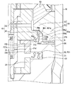
図8、図9に示すように、ボデー本体部21は、外側延出部211ではなく、中間延出部100を有している。中間延出部100は、ボデー本体部21の上端面において、径方向の中間位置から反噴孔側に向けて延びた円環状の部位であり、ボデー本体部21の上端面における径方向内側の端部及び径方向外側の端部の両方から離間している。中間延出部100は中間内面100a及び中間外面100bを有しており、中間内面100aは径方向内側を向き、中間外面100bは径方向外側を向いている。ボデー本体部21の上端面においては、径方向において本体内側上面21aと本体外側上面21bの間に中間延出部100が配置されている。本実施形態では、上記第1実施形態とは異なり、軸線方向において本体内側上面21aの方が本体外側上面21bよりも反噴孔側に配置されている。   As shown in FIGS. 8 and 9, the body main body 21 has an intermediate extension 100 instead of the outer extension 211. The intermediate extension portion 100 is an annular portion that extends from the radially intermediate position toward the non-injection hole side on the upper end surface of the body main body portion 21, and is radially inward at the upper end surface of the body main body portion 21. It is spaced from both the end and the radially outer end. The intermediate extension portion 100 has an intermediate inner surface 100a and an intermediate outer surface 100b. The intermediate inner surface 100a faces radially inward, and the intermediate outer surface 100b faces radially outward. On the upper end surface of the body main body 21, an intermediate extension 100 is disposed between the main body inner upper surface 21a and the main body outer upper surface 21b in the radial direction. In the present embodiment, unlike the first embodiment, the main body inner upper surface 21a is disposed closer to the injection hole side than the main body outer upper surface 21b in the axial direction.

本実施形態においても、上記第1実施形態と同様に、固定境界部Qには本体外側上面21b及び第2外側下面53aが含まれている。これに対して、中間延出部100は、径方向において中間外面100bが第2固定コア51の第2外側内面53bに重なる位置に配置されている。この場合、本実施形態では、中間延出部100の噴孔側の端部である基端部が固定境界部Qを径方向内側から覆っており、中間延出部100が覆い部に相当する。このため、上記第1実施形態と同様に、燃料噴射弁1の製造時において固定境界部Qに対する溶接作業が行われても、この固定境界部Qを通じてスパッタが流通路F26s,F31側に進入することが中間延出部100により抑制される。なお、中間延出部100は、第2切欠部N51の内部に噴孔側から入り込んだ状態になっている。   Also in the present embodiment, similarly to the first embodiment, the fixed boundary portion Q includes the main body outer upper surface 21b and the second outer lower surface 53a. On the other hand, the intermediate extension portion 100 is arranged at a position where the intermediate outer surface 100b overlaps the second outer inner surface 53b of the second fixed core 51 in the radial direction. In this case, in this embodiment, the base end, which is the end on the injection hole side of the intermediate extension portion 100, covers the fixed boundary portion Q from the radial inside, and the intermediate extension portion 100 corresponds to the covering portion. . Therefore, as in the first embodiment, even when welding is performed on the fixed boundary portion Q at the time of manufacturing the fuel injection valve 1, spatter enters the flow passages F26s and F31 through the fixed boundary portion Q. This is suppressed by the intermediate extension portion 100. In addition, the intermediate extension portion 100 is in a state of entering the inside of the second cutout portion N51 from the injection hole side.

上記第1実施形態と同様に、溶接部96は固定境界部Qよりも径方向内側まで延びている。このため、中間延出部100の基端寄りの一部が溶接部96に含まれている。   As in the first embodiment, the welded portion 96 extends radially inward of the fixed boundary portion Q. For this reason, a part of the intermediate extension portion 100 near the base end is included in the welded portion 96.

ボデー本体部21は、本体内側内面21dが径方向外側に向けて凹んだ本体凹部101を有している。本体凹部101は、軸線方向において本体内側内面21dの中間位置に配置されており、ボデー本体部21の全周にわたって形成されて円環状になっている。本体凹部101の内部空間は覆い下室S2を形成しており、摺動部材33と支持部材24との離間部分に連通している。径方向において本体凹部101の奥行き寸法は、径方向において中間外面100bと本体内側内面21dとの離間距離とほぼ同じになっている。   The body main body 21 has a main body concave portion 101 in which a main body inner inner surface 21d is dented outward in the radial direction. The main body concave portion 101 is arranged at an intermediate position of the main body inner inner surface 21d in the axial direction, is formed over the entire circumference of the body main body portion 21, and has an annular shape. The internal space of the main body concave portion 101 forms a covered lower chamber S2, and communicates with a space between the sliding member 33 and the support member 24. The depth dimension of the main body concave portion 101 in the radial direction is substantially the same as the separation distance between the intermediate outer surface 100b and the main body inner inner surface 21d in the radial direction.

ボデー本体部21においては、この本体凹部101よりも反噴孔側の部分が摺動部材33に対向しており、この部分を対向部102と称する。対向部102は、上記第1実施形態の対向部材94と同様に、摺動部材33を摺動させることで可動構造体Mの移動方向を案内するガイド部としての機能を発揮する。この場合、本体内側内面21dのうち本体凹部101よりも反噴孔側の部分が、対向部102において摺動面33aに対向する対向面に相当する。   In the body main body 21, a portion on the side opposite to the injection hole with respect to the main body concave portion 101 faces the sliding member 33, and this portion is referred to as a facing portion 102. The facing part 102 exhibits a function as a guide part for guiding the moving direction of the movable structure M by sliding the sliding member 33, similarly to the facing member 94 of the first embodiment. In this case, a portion of the main body inner inner surface 21d on the side opposite to the injection hole with respect to the main body concave portion 101 corresponds to a facing surface of the facing portion 102 facing the sliding surface 33a.

本実施形態でも、中間延出部100及び対向部102の上下に覆い上室S1及び覆い下室S2がある。このため、上記第1実施形態と同様に、図9に示すように、上室下向き燃圧PHaと下室上向き燃圧PLbとが打ち消し合い、上室上向き燃圧PHbと下室下向き燃圧PLaとが打ち消し合っている。   Also in the present embodiment, there are a covering upper chamber S1 and a covering lower chamber S2 above and below the intermediate extension section 100 and the facing section 102. Therefore, similarly to the first embodiment, as shown in FIG. 9, the upper chamber downward fuel pressure PHa and the lower chamber upward fuel pressure PLb cancel each other, and the upper chamber upward fuel pressure PHb and the lower chamber downward fuel pressure PLa cancel each other. ing.

(第3実施形態)
上記第2実施形態では、ボデー本体部21に本体凹部101が形成されていたが、第3実施形態では、図10に示すように、ボデー本体部21に本体凹部101が形成されていない。この構成では、中間延出部100及び対向部102の反噴孔側に覆い上室S1が設けられている一方で、上記第2実施形態とは異なり、噴孔側には覆い下室S2が設けられておらず、下室下向き燃圧PLa及び下室上向き燃圧PLbが生じないことになる。このため、上室下向き燃圧PHaと上室上向き燃圧PHbとが、ボデー本体部21と第2固定コア51とを軸線方向に離間させる向きに働くことが懸念される。しかしながら、上記第2実施形態と同様に、燃料噴射弁1の製造時において、固定境界部Qに対する溶接作業が行われても、この固定境界部Qを通じてスパッタが流通路F26s,F31側に進入することが中間延出部100により抑制される。このため、ボデー本体部21と第2固定コア51とを溶接により強固に接合することで、これらボデー本体部21と第2固定コア51とが軸線方向に離間するということを抑制できる。
(Third embodiment)
In the second embodiment, the main body concave portion 101 is formed in the body main body portion 21. However, in the third embodiment, as shown in FIG. 10, the main body concave portion 101 is not formed in the body main body portion 21. In this configuration, the upper cover S1 is provided on the side opposite to the injection hole of the intermediate extension portion 100 and the facing portion 102, but unlike the second embodiment, the lower cover S2 is provided on the injection hole side. It is not provided, so that the lower chamber downward fuel pressure PLa and the lower chamber upward fuel pressure PLb do not occur. For this reason, there is a concern that the upper chamber downward fuel pressure PHa and the upper chamber upward fuel pressure PHb may act in a direction that separates the body main body 21 and the second fixed core 51 in the axial direction. However, as in the second embodiment, even when welding is performed on the fixed boundary portion Q at the time of manufacturing the fuel injection valve 1, spatter enters the flow passages F26s and F31 through the fixed boundary portion Q. This is suppressed by the intermediate extension portion 100. For this reason, the body main body 21 and the second fixed core 51 are firmly joined by welding, so that the body main body 21 and the second fixed core 51 can be prevented from being separated from each other in the axial direction.

本実施形態では、ボデー本体部21において摺動部材33に対向する部分が対向部に相当し、この対向部を、可動構造体Mの移動を案内する案内部と称することもできる。また、ボデー本体部21の内周面ついて、摺動部材33の摺動面33aに対向する部分を対向部と称することもでき、この対向部も案内部と称することができる。   In the present embodiment, a portion facing the sliding member 33 in the body main body 21 corresponds to the facing portion, and the facing portion may be referred to as a guide portion for guiding the movement of the movable structure M. Further, a portion of the inner peripheral surface of the body main body 21 facing the sliding surface 33a of the sliding member 33 can be referred to as a facing portion, and this facing portion can also be referred to as a guide portion.

(他の実施形態)
以上、本開示による複数の実施形態について説明したが、本開示は、上記実施形態に限定して解釈されるものではなく、本開示の要旨を逸脱しない範囲内において種々の実施形態及び組み合わせに適用することができる。
(Other embodiments)
As described above, a plurality of embodiments according to the present disclosure have been described. However, the present disclosure is not construed as being limited to the above embodiments, and may be applied to various embodiments and combinations without departing from the gist of the present disclosure. can do.

変形例1として、上記各実施形態の可動コア41について、可動外側上面43aが可動内側上面42aよりも噴孔側に配置されているのではなく、反噴孔側に配置されていてもよい。また、これら可動外側上面43aと可動内側上面42aとが軸線方向において同じ位置に配置されていてもよい。すなわち、可動外側上面43aと可動内側上面42aとが径方向に隣り合う位置に配置されていてもよい。   As a first modification, in the movable core 41 of each of the above embodiments, the movable outer upper surface 43a may not be arranged on the injection hole side than the movable inner upper surface 42a, but may be arranged on the opposite injection hole side. The movable outer upper surface 43a and the movable inner upper surface 42a may be arranged at the same position in the axial direction. That is, the movable outer upper surface 43a and the movable inner upper surface 42a may be arranged at positions radially adjacent to each other.

変形例2として、上記各実施形態の可動コア41について、吸引面を2つ有するのではなく、吸引面を1つだけ有していてもよい。例えば、可動コア41が可動外側上面43aを有していない構成とする。この構成では、第1固定コア50が可動コア41と軸線方向に並ぶ位置に配置される一方で、第2固定コア51が可動コア41と径方向に並ぶ位置に配置される。この場合、第2固定コア51は、軸線方向において可動コア41に吸引される吸引面を有していないが、磁束の通路になることには変わりない。   As a second modification, the movable core 41 of each of the above embodiments may have only one suction surface instead of two suction surfaces. For example, the movable core 41 does not have the movable outer upper surface 43a. In this configuration, the first fixed core 50 is arranged at a position aligned with the movable core 41 in the axial direction, while the second fixed core 51 is arranged at a position aligned with the movable core 41 in the radial direction. In this case, the second fixed core 51 does not have an attraction surface that is attracted to the movable core 41 in the axial direction, but it still functions as a magnetic flux path.

変形例3として、上記各実施形態では、覆い上室S1が設けられていたが、上記第3実施形態にて覆い下室S2がなかったように、覆い上室S1がなくてもよい。例えば、上記第1実施形態において、覆い体90の覆い上面90bと第2固定コア51の第2下面51aとが重ねられ、覆い体90の覆い下面90cとボデー本体部21の上端面とが重ねられた構成とする。   As a third modification, in each of the above embodiments, the upper cover chamber S1 is provided. However, the upper cover chamber S1 may not be provided as in the third embodiment in which the lower cover chamber S2 is not provided. For example, in the first embodiment, the upper cover surface 90b of the cover 90 and the second lower surface 51a of the second fixed core 51 are overlapped, and the lower cover surface 90c of the cover 90 and the upper end surface of the body main body 21 overlap. Configuration.

変形例4として、上記第1実施形態では、ボデー本体部21及び第2固定コア51に、覆い体90を収容する本体切欠部N21及び第2切欠部N51が設けられていたが、これら切欠部N21,N51が設けられていなくてもよい。   As a fourth modification, in the first embodiment, the body main body 21 and the second fixed core 51 are provided with the main body cutout N21 and the second cutout N51 for accommodating the cover body 90. N21 and N51 need not be provided.

変形例5として、上記第1実施形態では、覆い部材93、対向部材94及びボデー本体部21の両方が非磁性体により形成されていたが、これら覆い部材93や対向部材94、ボデー本体部21は非磁性体でなく磁性体により形成されていてもよい。   As a fifth modification, in the first embodiment, both the cover member 93, the facing member 94, and the body main body 21 are formed of a non-magnetic material. May be formed of a magnetic material instead of a non-magnetic material.

ただし、覆い部材93及びボデー本体部21のうち一方は、可動コア41や第2固定コア51に比べて磁性が低い非磁性体等により形成されていることが好ましい。例えば、覆い部材93が磁性体により形成され、ボデー本体部21が非磁性体により形成された構成では、磁束が覆い部材93を通ったとしても、その磁束がボデー本体部21を通ることが生じにくくなっている。また、ボデー本体部21が磁性体により形成され、覆い部材93が非磁性体により形成された構成では、磁束が覆い部材93を通らないことで、その磁束がボデー本体部21を通ることが抑制される。したがって、いずれの構成でも、磁束が可動コア41の吸引面である可動外側上面43aを通らずにボデー本体部21から第2固定コア51に到達するということを抑制できる。   However, it is preferable that one of the cover member 93 and the body main body 21 is formed of a non-magnetic material or the like having lower magnetism than the movable core 41 and the second fixed core 51. For example, in a configuration in which the cover member 93 is formed of a magnetic material and the body main body 21 is formed of a non-magnetic material, even if the magnetic flux passes through the cover member 93, the magnetic flux may pass through the body main body 21. It has become difficult. In the configuration in which the body main body 21 is formed of a magnetic material and the cover member 93 is formed of a non-magnetic material, the magnetic flux does not pass through the cover member 93, so that the magnetic flux is prevented from passing through the body main body 21. Is done. Therefore, in any of the configurations, it is possible to suppress the magnetic flux from reaching the second fixed core 51 from the body main body 21 without passing through the movable outer upper surface 43a that is the suction surface of the movable core 41.

変形例6として、上記第1実施形態では、覆い体90が覆い部材93及び対向部材94という2つの部材により構成されていたが、覆い部材93だけが覆い体90を構成していてもよい。この場合でも、覆い部材93を、摺動部材33が摺動可能な形状及び大きさに設定することで、摺動部材33の移動を案内する機能や、摺動流通路F27sを形成する機能を、覆い部材93に付与することができる。   As the sixth modification, in the first embodiment, the cover 90 is constituted by two members, that is, the cover member 93 and the opposing member 94, but the cover member 93 alone may constitute the cover 90. Also in this case, by setting the shape and size of the cover member 93 so that the slide member 33 can slide, the function of guiding the movement of the slide member 33 and the function of forming the slide flow passage F27s are provided. , To the cover member 93.

変形例7として、上記各実施形態では、可動構造体Mが閉弁方向に移動する場合に、覆い上室S1がダンパ機能を発揮する構成になっていたが、覆い上室S1がダンパ機能を発揮しない構成になっていてもよい。例えば、摺動部材33の摺動面33aについて、その周方向全体を対向部材94に摺動させるのではなく、周方向において部分的に対向部材94に摺動させる構成とする。この構成では、対向部材94が覆い部材93の周方向において所定間隔で複数設けられている。この構成でも、複数の対向部材94は、摺動部材33を摺動させることで可動構造体Mの移動を案内することができる。   As a modified example 7, in each of the above embodiments, when the movable structure M moves in the valve closing direction, the cover upper chamber S1 is configured to exhibit the damper function. However, the cover upper chamber S1 performs the damper function. It may be configured not to exhibit. For example, the sliding surface 33a of the sliding member 33 is configured not to slide in the entire circumferential direction to the opposing member 94 but to slide partially in the circumferential direction to the opposing member 94. In this configuration, a plurality of opposing members 94 are provided at predetermined intervals in the circumferential direction of the covering member 93. Also in this configuration, the plurality of opposing members 94 can guide the movement of the movable structure M by sliding the sliding member 33.

変形例8として、上記各実施形態では、固定境界部Qの全体が溶接部96に含まれていたが、溶接部96には、少なくとも固定境界部Qの径方向外側の端部が含まれていればよい。この構成では、溶接部96には、ボデー本体部21の一部及び第2固定コア51の一部が含まれる一方で、覆い部材93は含まれない。すなわち、溶接部96によっては、覆い部材93がボデー本体部21及び第2固定コア51に固定されない。この場合、軸線方向において、覆い部材93の外周面である覆い外面90aの高さ寸法が、本体外側内面21cの高さ寸法と第2外側内面53bの高さ寸法との合計とほぼ同じになっていることが好ましい。これは、覆い部材93の位置が噴孔側にずれることが、ボデー本体部21の切欠傾斜面N21aにより規制され、反噴孔側にずれることが、第2固定コア51の切欠傾斜面N51aにより規制されるためである。   As Modification 8, in the above embodiments, the entirety of the fixed boundary portion Q is included in the welded portion 96, but the welded portion 96 includes at least a radially outer end of the fixed boundary portion Q. Just do it. In this configuration, the welded portion 96 includes a part of the body main body 21 and a part of the second fixed core 51, but does not include the cover member 93. That is, the cover member 93 is not fixed to the body main body 21 and the second fixed core 51 depending on the welding portion 96. In this case, in the axial direction, the height of the cover outer surface 90a, which is the outer peripheral surface of the cover member 93, is substantially the same as the sum of the height of the main body outer inner surface 21c and the height of the second outer inner surface 53b. Is preferred. This is because the shift of the position of the cover member 93 to the injection hole side is regulated by the cutout inclined surface N21a of the body main body portion 21 and the shift to the counter injection hole side is prevented by the cutout inclined surface N51a of the second fixed core 51. Because it is regulated.

変形例9として、上記第1実施形態の覆い体90において、覆い部材93及び対向部材94の両方が非磁性体により形成されていたが、対向部材94は磁性体により形成されていてもよい。この場合、燃料噴射弁1の設計段階において、対向部材94の材料を選択する場合に、磁性よりも硬度や強度を優先することができるため、摺動部材33の摺動に伴って対向部材94の摩耗や変形が生じるということを抑制できる。   As a ninth modification, in the cover body 90 of the first embodiment, both the cover member 93 and the facing member 94 are formed of a non-magnetic material, but the facing member 94 may be formed of a magnetic material. In this case, in selecting the material of the opposing member 94 in the design stage of the fuel injection valve 1, the hardness and strength can be given priority over the magnetism. Can be prevented from being worn or deformed.

変形例10として、上記各実施形態では、固定境界部Qについて、溶接に伴って溶接部96が形成されていたが、溶接部96は形成されていなくてもよい。すなわち、第2固定コア51とボデー本体部21とは溶接されていなくてもよい。この場合でも、固定境界部Qが覆い部材93により覆われていることで、燃料が固定境界部Qに到達しにくくなる。仮に到達したとしても、第2固定コア51及びボデー本体部21と覆い部材93との隙間が狭小空間になっていることに起因して、固定境界部Qに加わる燃圧が低減されやすくなる。このため、第2固定コア51とボデー本体部21とが溶接されていなくても、軸線方向において第2固定コア51とボデー本体部21とが離間することや、固定境界部Qにて燃料が漏れ出すことなどを抑制できる。   As a tenth modification, in each of the above embodiments, the welded portion 96 is formed at the fixed boundary portion Q with the welding, but the welded portion 96 may not be formed. That is, the second fixed core 51 and the body main body 21 need not be welded. Even in this case, since the fixed boundary portion Q is covered with the covering member 93, the fuel does not easily reach the fixed boundary portion Q. Even if it reaches, the fuel pressure applied to the fixed boundary portion Q is likely to be reduced because the gap between the second fixed core 51 and the body main body 21 and the cover member 93 is a narrow space. For this reason, even if the second fixed core 51 and the body main body 21 are not welded, the second fixed core 51 and the body main body 21 are separated from each other in the axial direction, and the fuel flows at the fixed boundary Q. Leakage can be suppressed.

変形例11として、上記各実施形態では、ガイド部30b,31b及び摺動部材33の3箇所でノズルボデー20に対する可動構造体Mの移動がガイドされていたが、ガイド部30b,31b及び摺動部材33のいずれか2箇所でガイドされてもよい。例えば、噴孔側ガイド部30b及び摺動部材33の2箇所でガイドされる構成とする。この構成によれば、ガイド位置が3箇所である構成に比べて、ノズルボデー20に対する可動構造体Mの同軸度の精度確保が容易になる。このため、可動構造体Mが移動する際にノズルボデー20に対するフリクションが増大することを抑制しやすくなる。   As a modification 11, in the above embodiments, the movement of the movable structure M with respect to the nozzle body 20 is guided at the three locations of the guide portions 30b and 31b and the sliding member 33, but the guide portions 30b and 31b and the sliding member 33 may be guided at any two places. For example, it is configured to be guided at two places of the injection hole side guide portion 30b and the sliding member 33. According to this configuration, it is easier to ensure the accuracy of the coaxiality of the movable structure M with respect to the nozzle body 20 as compared with the configuration in which the guide positions are three places. For this reason, it is easy to suppress an increase in friction with the nozzle body 20 when the movable structure M moves.

変形例12として、上記各実施形態では、可動構造体Mが移動部材35及び押付用弾性部材SP2を有していたが、可動構造体Mは、これら移動部材35及び押付用弾性部材SP2を有していなくてもよい。この構成でも、可動流通路F20には絞り通路F22がオリフィス32aにより形成されているため、上流燃圧PHと下流燃圧PLとの間に圧力差が生じる。このため、可動構造体Mが閉弁方向に移動する最中において、覆い上室S1がダンパ機能を発揮することで可動構造体Mにブレーキ力を作用させることができる。   As Modified Example 12, in each of the above embodiments, the movable structure M has the moving member 35 and the pressing elastic member SP2, but the movable structure M has the moving member 35 and the pressing elastic member SP2. You don't have to. Also in this configuration, since the throttle passage F22 is formed in the movable flow passage F20 by the orifice 32a, a pressure difference occurs between the upstream fuel pressure PH and the downstream fuel pressure PL. For this reason, while the movable structure M moves in the valve closing direction, the covering upper chamber S1 exerts a damper function, so that a braking force can be applied to the movable structure M.

変形例13として、上記各実施形態では、ストッパ55において第1固定コア50よりも噴孔側に突出した部分が、固定コア50,51と可動コア41との間にギャップを確保する凸部になっていたが、凸部は可動構造体Mに設けられていてもよい。例えば、図11に示すように、可動構造体Mにおいて連結部材31が可動コア41よりも反噴孔側に突出しており、この突出部分が凸部になっている構成とする。この構成では、ストッパ55が第1固定コア50よりも噴孔側に突出していない。このため、連結部材31とストッパ55とが当接することで可動構造体Mの移動が規制された場合に、可動コア41から連結部材31が突出した長さ分だけ、固定コア50,51と可動コア41との間にギャップが確保される。   As a thirteenth modification, in each of the above embodiments, the portion of the stopper 55 protruding toward the injection hole side from the first fixed core 50 is formed as a convex portion that secures a gap between the fixed cores 50 and 51 and the movable core 41. However, the protrusion may be provided on the movable structure M. For example, as shown in FIG. 11, in the movable structure M, the connecting member 31 protrudes more toward the injection hole side than the movable core 41, and the protruding portion is a convex portion. In this configuration, the stopper 55 does not protrude further toward the injection hole than the first fixed core 50. For this reason, when the movement of the movable structure M is restricted by the contact between the connecting member 31 and the stopper 55, the fixed cores 50 and 51 are movable with the fixed core 50, 51 by the length of the connecting member 31 protruding from the movable core 41. A gap is secured between the core 41 and the core 41.

変形例14として、上記各実施形態において、第1吸引面と固定コアとのギャップと、第2吸引面と固定コアとのギャップとを、同じ大きさに設定してもよいし、異なる大きさに設定してもよい。異なる大きさに設定する場合、第1吸引面および第2吸引面のうち、通過する磁束の量が少ない方の吸引面について、他方の吸引面よりもギャップを大きくすることが望ましい。その理由について以下に説明する。   As a modification 14, in each of the above embodiments, the gap between the first suction surface and the fixed core and the gap between the second suction surface and the fixed core may be set to the same size or different sizes. May be set. When different sizes are set, it is desirable to make the gap of the first suction surface and the second suction surface that has a smaller amount of magnetic flux passing through the gap larger than that of the other suction surface. The reason will be described below.

固定コアと吸引面との間に燃料が薄膜状に充満した状態では、リンキング作用により、吸引面が固定コアから引き剥がされにくくなっている。そして、固定コアと吸引面とのギャップを小さくするほどリンキング作用が大きくなり、通電オフに対する閉弁作動開始の応答性が悪くなる。しかし、リンキング作用低減を図るべくギャップを大きくすると、その背反として吸引力が小さくなってしまう。この点を鑑みると、磁束量が少ない方の吸引面については、ギャップを小さくしても吸引力向上に大きくは寄与しないので、ギャップを大きくしてリンキング作用低減を図った方が有効である。   In a state where the fuel is filled in a thin film between the fixed core and the suction surface, the suction surface is hardly peeled off from the fixed core by the linking action. Then, as the gap between the fixed core and the suction surface is reduced, the linking action is increased, and the responsiveness of starting the valve closing operation in response to turning off the power is deteriorated. However, if the gap is increased to reduce the linking action, the suction force will be reduced as a contradiction. In view of this point, for the suction surface having a smaller amount of magnetic flux, even if the gap is reduced, it does not greatly contribute to the improvement of the suction force. Therefore, it is more effective to reduce the linking action by increasing the gap.

以上により、第1吸引面および第2吸引面のうち、磁束量が少ない方の吸引面について、他方の吸引面よりもギャップを大きくすることが望ましい。なお、上記各実施形態の例では、径方向外側に位置する吸引面(第2吸引面)を通過する磁束量は、径方向内側に位置する吸引面(第1吸引面)を通過する磁束量よりも少ない。よって、第2吸引面のギャップを第1吸引面のギャップよりも大きく設定している。   As described above, it is desirable that the gap between the first suction surface and the second suction surface having the smaller amount of magnetic flux be larger than the gap between the other suction surface. In the examples of the above embodiments, the amount of magnetic flux passing through the suction surface (second suction surface) positioned radially outward is the amount of magnetic flux passing through the suction surface (first suction surface) positioned radially inward. Less than. Therefore, the gap of the second suction surface is set to be larger than the gap of the first suction surface.

1…燃料噴射弁、21…通路形成部としてのボデー本体部、23a…噴孔、32a…絞り部としてのオリフィス、41…可動コア、42a…第1吸引面としての可動内側上面42a、43a…第2吸引面としての可動外側上面43a、50…第1固定コア、51…第2固定コア、60…短絡規制部を構成する非磁性部材、70…コイル、90b…上面としての覆い上面、90c…下面としての覆い下面、93…覆い部を構成する覆い部材、94…案内部を構成する対向部材、96…溶接部、100…覆い部としての中間延出部、F…流通路、F21…メイン通路を構成する流通路、F22…メイン通路を構成する絞り流通路、F23…メイン通路を構成する流通路、F24s…サブ通路を構成する流通路、F25s…サブ通路を構成する流通路、F26s…サブ通路を構成する流通路、F27s…サブ通路を構成し別流通路に相当する摺動流通路、M…可動構造体、Q…固定境界部、S1…覆い上室。   DESCRIPTION OF SYMBOLS 1 ... Fuel injection valve, 21 ... Body body part as a passage formation part, 23a ... Injection hole, 32a ... Orifice as a throttle part, 41 ... Movable core, 42a ... Movable inner upper surface 42a, 43a as a first suction surface ... Movable outer upper surfaces 43a and 50 as second suction surfaces, 50: first fixed core, 51: second fixed core, 60: non-magnetic member constituting short-circuit restriction portion, 70: coil, 90b: covering upper surface as upper surface, 90c ... lower surface of the cover as a lower surface, 93 ... a cover member constituting a cover portion, 94 ... an opposing member constituting a guide portion, 96 ... a welded portion, 100 ... an intermediate extension portion as a cover portion, F ... a flow passage, F21 ... F22: Restricted flow path that forms the main path, F23: Flow path that forms the main path, F24s: Flow path that forms the sub path, F25s: Flow that forms the sub path , Flow passage constituting the F26s ... sub passage, the sliding passage corresponding to a different flow path constitutes the F27s ... sub passage, M ... movable structures, Q ... rigid boundary portion, S1 ... covering the upper chamber.

Claims (8)

燃料を噴孔(23a)から噴射する燃料噴射弁(1)であって、
通電により磁束を生じさせるコイル(70)と、
前記噴孔に燃料を流通させる流通路(F)の一部を形成し、前記磁束の通路になる固定コア(51)と、
前記磁束の通路になることで前記固定コアに吸引される可動コア(41)と、
前記コイルの軸線方向において前記固定コアよりも下流側に設けられ、前記流通路(F)の一部を形成する通路形成部(21)と、
前記通路形成部と前記固定コアとの境界部である固定境界部を前記流通路側から覆っている覆い部(93,100)と、
を備え
前記通路形成部及び前記覆い部の少なくとも一方は、前記固定コアに比べて磁性が低い、燃料噴射弁。
A fuel injection valve (1) for injecting fuel from an injection hole (23a),
A coil (70) for generating a magnetic flux when energized;
A fixed core (51) that forms a part of a flow passage (F) through which fuel flows through the injection hole, and serves as a passage for the magnetic flux;
A movable core (41) that is attracted to the fixed core by being a passage of the magnetic flux;
A passage forming portion (21) provided downstream of the fixed core in the axial direction of the coil and forming a part of the flow passage (F);
A covering portion (93, 100) for covering a fixed boundary portion, which is a boundary portion between the passage forming portion and the fixed core, from a side of the flow passage;
Equipped with a,
At least one of the passage forming portion and the covering portion has lower magnetism than the fixed core .
前記覆い部は、前記通路形成部及び前記固定コアから独立した部材である、請求項1に記載の燃料噴射弁。 The fuel injection valve according to claim 1, wherein the covering portion is a member independent of the passage forming portion and the fixed core. 前記固定境界部について前記通路形成部と前記固定コアとが溶接により一体化された溶接部(96)を備え、
前記溶接部には、前記固定境界部よりも前記流通路側において前記覆い部の一部が含まれている、請求項に記載の燃料噴射弁。
A welding portion (96) in which the passage forming portion and the fixed core are integrated by welding with respect to the fixed boundary portion;
The fuel injection valve according to claim 2 , wherein the welded portion includes a part of the covering portion on the side of the flow passage from the fixed boundary portion.
前記覆い部は、前記通路形成部及び前記固定コアの両方から前記流通路側に突出しており、
前記覆い部においては、前記噴孔側を向いた下面(90c)と、前記噴孔とは反対側を向いた上面(90b)と、の両方がそれぞれ前記流通路を形成している、請求項1〜のいずれか1つに記載の燃料噴射弁。
The covering portion projects toward the flow passage from both the passage forming portion and the fixed core,
The said cover part WHEREIN: Both the lower surface (90c) facing the said injection hole side and the upper surface (90b) facing the opposite side to the said injection hole respectively form the said flow path. The fuel injection valve according to any one of claims 1 to 3 .
前記可動コアを含んで構成され、前記可動コアが前記磁束の通路になって前記固定コアに吸引されることで前記コイルの軸線方向に変位する可動構造体(M)と、
前記覆い部を挟んで前記固定境界部とは反対側に設けられ、前記固定コアによる吸引に伴って前記可動構造体が移動する場合に、前記可動構造体の移動を案内する案内部(94)と、
を備え、
前記案内部は、前記覆い部により支持されている、請求項1〜のいずれか1つに記載の燃料噴射弁。
A movable structure (M) configured to include the movable core, the movable core being displaced in the axial direction of the coil by being attracted to the fixed core as a path of the magnetic flux,
A guide portion (94) provided on the opposite side to the fixed boundary portion with the cover portion interposed therebetween, and for guiding the movement of the movable structure when the movable structure moves along with suction by the fixed core; When,
With
The fuel injection valve according to any one of claims 1 to 4 , wherein the guide section is supported by the cover section.
前記通路形成部を含み、前記可動構造体を移動可能な状態で内部に収容しているボデー(B)を備え、
前記流通路は、
前記可動構造体の内部に設けられたメイン通路(F21,F22,F23)と、
前記可動構造体と前記ボデーとの間に設けられたサブ通路(F24s,F25s,F26s,F27s)と、
を有し、
前記メイン通路は、
前記メイン通路の通路面積を部分的に小さくして流量を絞り且つ前記可動構造体が有する絞り部(32a)により形成された絞り流通路(F22)を有し、
前記サブ通路は、 前記可動構造体と前記案内部との隙間により形成された別流通路(F27s)と、
前記別流通路よりも上流側において前記可動構造体と前記覆い部との隙間により形成され、前記別流通路よりも通路面積が大きい覆い上室(S1)と、
を有している、請求項に記載の燃料噴射弁。
A body (B) that includes the passage forming portion and accommodates the movable structure therein in a movable state,
The flow passage,
A main passage (F21, F22, F23) provided inside the movable structure;
Sub passages (F24s, F25s, F26s, F27s) provided between the movable structure and the body;
Has,
The main passage,
A throttle flow passage (F22) formed by a throttle portion (32a) of the movable structure by reducing a flow area by partially reducing a passage area of the main passage;
The sub-passage is a separate flow passage (F27s) formed by a gap between the movable structure and the guide portion;
A cover upper chamber (S1) formed by a gap between the movable structure and the cover on the upstream side of the separate passage, and having a larger passage area than the separate passage;
The fuel injection valve according to claim 5 , comprising:
前記覆い部及び前記案内部は、互いに独立した別部材により形成されており、
前記通路形成部及び前記覆い部の両方が前記固定コアに比べて磁性が低い、請求項又はに記載の燃料噴射弁。
The cover portion and the guide portion are formed by separate members independent of each other,
Both said passage forming portion and the cover portion is lower magnetic compared to the fixed core, a fuel injection valve according to claim 5 or 6.
前記固定コアを第2固定コア(51)と称し、
前記第2固定コアよりも上流側において前記流通路(F)の一部を形成し、前記磁束の通路になる第1固定コア(50)を備え、
前記可動コアは、
前記磁束が通ることで前記第1固定コアに吸引される第1吸引面(42a)と、
前記第1吸引面とは反対向きに前記磁束が通ることで前記第2固定コアに吸引される第2吸引面(43a)と、
を有し、
前記磁束が前記可動コアを通らずに前記第1固定コアと前記第2固定コアとの間を短絡して通ることを規制する短絡規制部(60)が、前記第1固定コアと前記第2固定コアとの間に設けられており、
前記固定境界部は、前記第2固定コアと前記通路形成部との境界部である、請求項1〜のいずれか1つに記載の燃料噴射弁。
The fixed core is referred to as a second fixed core (51),
A first fixed core (50) that forms a part of the flow passage (F) upstream of the second fixed core and serves as a passage for the magnetic flux;
The movable core is
A first suction surface (42a) that is attracted to the first fixed core by passing the magnetic flux,
A second suction surface (43a) that is attracted to the second fixed core by passing the magnetic flux in a direction opposite to the first suction surface;
Has,
A short-circuit restricting portion (60) for restricting the magnetic flux from passing through the first fixed core and the second fixed core without passing through the movable core by a short-circuit is provided between the first fixed core and the second fixed core. It is provided between the fixed core and
The fuel injection valve according to any one of claims 1 to 7 , wherein the fixed boundary is a boundary between the second fixed core and the passage forming portion.
JP2017040729A 2017-03-03 2017-03-03 Fuel injection valve Active JP6677194B2 (en)

Priority Applications (5)

Application Number Priority Date Filing Date Title
JP2017040729A JP6677194B2 (en) 2017-03-03 2017-03-03 Fuel injection valve
PCT/JP2018/005447 WO2018159325A1 (en) 2017-03-03 2018-02-16 Fuel injection valve
CN201880013938.3A CN110337538B (en) 2017-03-03 2018-02-16 Fuel injection valve
DE112018001131.3T DE112018001131B4 (en) 2017-03-03 2018-02-16 Fuel injection valve
US16/539,223 US11162465B2 (en) 2017-03-03 2019-08-13 Fuel injection valve

Applications Claiming Priority (1)

Application Number Priority Date Filing Date Title
JP2017040729A JP6677194B2 (en) 2017-03-03 2017-03-03 Fuel injection valve

Publications (3)

Publication Number Publication Date
JP2018145849A JP2018145849A (en) 2018-09-20
JP2018145849A5 JP2018145849A5 (en) 2019-05-09
JP6677194B2 true JP6677194B2 (en) 2020-04-08

Family

ID=63371062

Family Applications (1)

Application Number Title Priority Date Filing Date
JP2017040729A Active JP6677194B2 (en) 2017-03-03 2017-03-03 Fuel injection valve

Country Status (5)

Country Link
US (1) US11162465B2 (en)
JP (1) JP6677194B2 (en)
CN (1) CN110337538B (en)
DE (1) DE112018001131B4 (en)
WO (1) WO2018159325A1 (en)

Families Citing this family (2)

* Cited by examiner, † Cited by third party
Publication number Priority date Publication date Assignee Title
JP6677195B2 (en) 2017-03-03 2020-04-08 株式会社デンソー Fuel injection valve and method of manufacturing fuel injection valve
JP6662364B2 (en) 2017-03-03 2020-03-11 株式会社デンソー Fuel injection valve and fuel injection system

Family Cites Families (17)

* Cited by examiner, † Cited by third party
Publication number Priority date Publication date Assignee Title
JP3505054B2 (en) * 1997-01-17 2004-03-08 株式会社日立製作所 Injector
US6334580B2 (en) * 1999-05-26 2002-01-01 Siemens Automotive Corporation Gaseous injector with columnated jet oriface flow directing device
DE19948238A1 (en) * 1999-10-07 2001-04-19 Bosch Gmbh Robert Fuel injector
JP3819907B2 (en) * 2004-02-27 2006-09-13 株式会社ケーヒン Electromagnetic fuel injection valve and manufacturing method thereof
JP3987864B2 (en) * 2005-06-15 2007-10-10 三菱電機株式会社 Fuel injection valve
JP4211814B2 (en) * 2006-07-13 2009-01-21 株式会社日立製作所 Electromagnetic fuel injection valve
DE102012012480A1 (en) * 2011-06-24 2012-12-27 Caterpillar Inc. Common rail fuel injector for use in internal combustion engine, has check needle including opening hydraulic surface exposed to fluid pressure of nozzle supply passage and closing hydraulic surface exposed to fluid pressure of chamber
JP5822269B2 (en) * 2011-11-11 2015-11-24 株式会社ケーヒン Electromagnetic fuel injection valve
DE102012223259A1 (en) * 2012-12-14 2014-06-18 Robert Bosch Gmbh Fuel injection valve
EP2799705A1 (en) * 2013-05-01 2014-11-05 Delphi International Operations Luxembourg S.à r.l. Fuel Injector Assembly and Sleeve Insert
JP6086959B2 (en) 2015-08-19 2017-03-01 兼藤産業株式会社 Signal attenuator for optical drop cable and signal attenuation / resumption method using the same
JP6380323B2 (en) 2015-10-02 2018-08-29 株式会社デンソー Fuel injection device
JP6520983B2 (en) * 2016-07-28 2019-05-29 株式会社デンソー Fuel injection valve and method of manufacturing fuel injection valve
DE112018000562B4 (en) 2017-01-27 2022-03-31 Denso Corporation FUEL INJECTION VALVE
JP6645460B2 (en) * 2017-01-27 2020-02-14 株式会社デンソー Fuel injection valve
WO2018159326A1 (en) 2017-03-03 2018-09-07 株式会社デンソー Fuel injection valve and fuel injection system
JP6677195B2 (en) 2017-03-03 2020-04-08 株式会社デンソー Fuel injection valve and method of manufacturing fuel injection valve

Also Published As

Publication number Publication date
WO2018159325A1 (en) 2018-09-07
CN110337538B (en) 2021-11-19
US11162465B2 (en) 2021-11-02
JP2018145849A (en) 2018-09-20
CN110337538A (en) 2019-10-15
DE112018001131B4 (en) 2024-08-08
US20190360442A1 (en) 2019-11-28
DE112018001131T5 (en) 2019-12-05

Similar Documents

Publication Publication Date Title
JP5537472B2 (en) Fuel injection device
JP5239965B2 (en) Fuel injection valve
US11319911B2 (en) Fuel injection valve
JP5482267B2 (en) Fuel injection valve
JP6677194B2 (en) Fuel injection valve
JP6645460B2 (en) Fuel injection valve
JP6677195B2 (en) Fuel injection valve and method of manufacturing fuel injection valve
JP4453745B2 (en) Fuel injection valve
JP5321473B2 (en) Fuel injection valve
JP5857952B2 (en) Fuel injection valve
JP6275902B2 (en) Fuel injection device
JP6020194B2 (en) Fuel injection valve
JP7291585B2 (en) fuel injector
JP6453381B2 (en) Fuel injection device
JP6662364B2 (en) Fuel injection valve and fuel injection system
JP6063894B2 (en) Fuel injection device
US7093779B2 (en) Fuel injection valve
JP6339461B2 (en) Fuel injection valve
JP7495908B2 (en) Fuel Injection Valve
JP6655575B2 (en) Electromagnetic fuel injection valve
JP6913816B2 (en) Fuel injection valve and its assembly method
JP6669282B2 (en) Fuel injection device
JP6673797B2 (en) Fuel injection valve
JP2005009421A (en) Solenoid operated fuel injection valve
JP2019039437A (en) Fuel injection device

Legal Events

Date Code Title Description
A521 Request for written amendment filed

Free format text: JAPANESE INTERMEDIATE CODE: A523

Effective date: 20190320

A621 Written request for application examination

Free format text: JAPANESE INTERMEDIATE CODE: A621

Effective date: 20190320

TRDD Decision of grant or rejection written
A01 Written decision to grant a patent or to grant a registration (utility model)

Free format text: JAPANESE INTERMEDIATE CODE: A01

Effective date: 20200212

A61 First payment of annual fees (during grant procedure)

Free format text: JAPANESE INTERMEDIATE CODE: A61

Effective date: 20200225

R150 Certificate of patent or registration of utility model

Ref document number: 6677194

Country of ref document: JP

Free format text: JAPANESE INTERMEDIATE CODE: R150

R250 Receipt of annual fees

Free format text: JAPANESE INTERMEDIATE CODE: R250

R250 Receipt of annual fees

Free format text: JAPANESE INTERMEDIATE CODE: R250