JP6674516B2 - Slide rail assembly - Google Patents
Slide rail assembly Download PDFInfo
- Publication number
- JP6674516B2 JP6674516B2 JP2018172043A JP2018172043A JP6674516B2 JP 6674516 B2 JP6674516 B2 JP 6674516B2 JP 2018172043 A JP2018172043 A JP 2018172043A JP 2018172043 A JP2018172043 A JP 2018172043A JP 6674516 B2 JP6674516 B2 JP 6674516B2
- Authority
- JP
- Japan
- Prior art keywords
- rail
- respect
- base
- block
- furniture
- Prior art date
- Legal status (The legal status is an assumption and is not a legal conclusion. Google has not performed a legal analysis and makes no representation as to the accuracy of the status listed.)
- Active
Links
- 239000012858 resilient material Substances 0.000 claims 1
- 238000010586 diagram Methods 0.000 description 3
- 230000007246 mechanism Effects 0.000 description 3
- 230000000712 assembly Effects 0.000 description 2
- 238000000429 assembly Methods 0.000 description 2
- 239000013013 elastic material Substances 0.000 description 2
- 239000000463 material Substances 0.000 description 2
- 238000000034 method Methods 0.000 description 2
- 230000004044 response Effects 0.000 description 2
- 230000000694 effects Effects 0.000 description 1
- 239000007769 metal material Substances 0.000 description 1
- 230000004048 modification Effects 0.000 description 1
- 238000012986 modification Methods 0.000 description 1
- 230000008569 process Effects 0.000 description 1
Images


Classifications
-
- A—HUMAN NECESSITIES
- A47—FURNITURE; DOMESTIC ARTICLES OR APPLIANCES; COFFEE MILLS; SPICE MILLS; SUCTION CLEANERS IN GENERAL
- A47B—TABLES; DESKS; OFFICE FURNITURE; CABINETS; DRAWERS; GENERAL DETAILS OF FURNITURE
- A47B88/00—Drawers for tables, cabinets or like furniture; Guides for drawers
- A47B88/40—Sliding drawers; Slides or guides therefor
- A47B88/407—Adjustably or detachably mounted drawers
-
- A—HUMAN NECESSITIES
- A47—FURNITURE; DOMESTIC ARTICLES OR APPLIANCES; COFFEE MILLS; SPICE MILLS; SUCTION CLEANERS IN GENERAL
- A47B—TABLES; DESKS; OFFICE FURNITURE; CABINETS; DRAWERS; GENERAL DETAILS OF FURNITURE
- A47B88/00—Drawers for tables, cabinets or like furniture; Guides for drawers
- A47B88/40—Sliding drawers; Slides or guides therefor
- A47B88/403—Drawer slides being extractable on two or more sides of the cabinet
-
- A—HUMAN NECESSITIES
- A47—FURNITURE; DOMESTIC ARTICLES OR APPLIANCES; COFFEE MILLS; SPICE MILLS; SUCTION CLEANERS IN GENERAL
- A47B—TABLES; DESKS; OFFICE FURNITURE; CABINETS; DRAWERS; GENERAL DETAILS OF FURNITURE
- A47B88/00—Drawers for tables, cabinets or like furniture; Guides for drawers
- A47B88/40—Sliding drawers; Slides or guides therefor
- A47B88/423—Fastening devices for slides or guides
- A47B88/427—Fastening devices for slides or guides at drawer side
-
- A—HUMAN NECESSITIES
- A47—FURNITURE; DOMESTIC ARTICLES OR APPLIANCES; COFFEE MILLS; SPICE MILLS; SUCTION CLEANERS IN GENERAL
- A47B—TABLES; DESKS; OFFICE FURNITURE; CABINETS; DRAWERS; GENERAL DETAILS OF FURNITURE
- A47B88/00—Drawers for tables, cabinets or like furniture; Guides for drawers
- A47B88/40—Sliding drawers; Slides or guides therefor
- A47B88/473—Braking devices, e.g. linear or rotational dampers or friction brakes; Buffers; End stops
- A47B88/477—Buffers; End stops
-
- A—HUMAN NECESSITIES
- A47—FURNITURE; DOMESTIC ARTICLES OR APPLIANCES; COFFEE MILLS; SPICE MILLS; SUCTION CLEANERS IN GENERAL
- A47B—TABLES; DESKS; OFFICE FURNITURE; CABINETS; DRAWERS; GENERAL DETAILS OF FURNITURE
- A47B88/00—Drawers for tables, cabinets or like furniture; Guides for drawers
- A47B88/40—Sliding drawers; Slides or guides therefor
- A47B88/483—Sliding drawers; Slides or guides therefor with single extensible guides or parts
-
- F—MECHANICAL ENGINEERING; LIGHTING; HEATING; WEAPONS; BLASTING
- F16—ENGINEERING ELEMENTS AND UNITS; GENERAL MEASURES FOR PRODUCING AND MAINTAINING EFFECTIVE FUNCTIONING OF MACHINES OR INSTALLATIONS; THERMAL INSULATION IN GENERAL
- F16C—SHAFTS; FLEXIBLE SHAFTS; ELEMENTS OR CRANKSHAFT MECHANISMS; ROTARY BODIES OTHER THAN GEARING ELEMENTS; BEARINGS
- F16C2314/00—Personal or domestic articles, e.g. household appliances such as washing machines, dryers
- F16C2314/70—Furniture
- F16C2314/72—Drawers
Landscapes
- Drawers Of Furniture (AREA)
Description
本発明は、家具システムに適用可能なスライドレールアセンブリに関し、より具体的には、ユーザーの要望に応じたスライドレールアセンブリの取り付けを可能にするフィッティング部材(fitting member)に関する。 TECHNICAL FIELD The present invention relates to a slide rail assembly applicable to a furniture system, and more particularly, to a fitting member capable of mounting a slide rail assembly according to a user's request.
一般に、スライドレールアセンブリは、広範囲の用途において実施される。例えば、スライドレールアセンブリは、家具システムに又は電子機器のためのラックシステムに適用できる。家具システムに適用されたスライドレールアセンブリを例に取ってみる。スライドレールアセンブリは、固定レールと、固定レールに対して長手方向に移動可能なスライドレールとを含む。固定レールは、通常、キャビネットに固定的に取り付けられ、スライドレールは、引き出しをキャビネットに対して動かすことができるように引き出しを保持するように構成されている。 Generally, slide rail assemblies are implemented in a wide range of applications. For example, a slide rail assembly can be applied to a furniture system or a rack system for electronics. Take as an example a slide rail assembly applied to a furniture system. The slide rail assembly includes a fixed rail and a slide rail movable longitudinally with respect to the fixed rail. The fixed rail is typically fixedly attached to the cabinet, and the slide rail is configured to hold the drawer so that the drawer can be moved relative to the cabinet.
しかしながら、市場には様々な要望がある。この点を説明するために、第1の種類の要望では、引き出し(スライドレール)は、引き出しがキャビネット(固定レール)に対して引っ込められるときに同じ位置に位置することが望ましい。あるいは、許容誤差(tolerance)を考慮した第2の種類の要望では、引き出し(スライドレール)は、引き出しとキャビネット(固定レール)との間の深さを調整する調整機構を有することが望ましい。したがって、引き出し(スライドレール)がキャビネットに対して引っ込めた場合に、引き出しは異なる位置(すなわち、異なる長手方向位置)に位置することができる。上述した調節機構は、引き出し(スライドレール)とキャビネット(固定レール)との間の許容誤差の低減の問題に関するものであってもよい。 However, there are various demands on the market. To illustrate this point, in a first type of desire, it is desirable that the drawer (slide rail) be located in the same position when the drawer is retracted relative to the cabinet (fixed rail). Alternatively, according to a second type of demand in view of tolerance, it is desirable that the drawer (slide rail) has an adjusting mechanism for adjusting the depth between the drawer and the cabinet (fixed rail). Thus, if the drawer (slide rail) is retracted with respect to the cabinet, the drawer can be located at a different position (ie, a different longitudinal position). The adjustment mechanism described above may relate to the problem of reducing the tolerance between the drawer (slide rail) and the cabinet (fixed rail).
関連する先行技術では、特許文献1に引き出しのためのスライドレールアセンブリに引き出しをリリース可能に接続することができる装置(7)が開示されている。引き出し(2)が取り付けられた状態にあるとき、引き出しは弾性領域(12)を通じてスライドレール(5)の保持部(13)に接触できる。
弾性領域(12)は、装置(7)の支持ベース(11)及びスライドレール(5)の保持部(13)のためのクッションである。そのため、取り付けプロセスの間の引き出し(2)とスライドレール(5)との間の長さの許容誤差が解消され得る。ここでは、上記の特許文献が参考として含まれる。
In the related prior art,
The elastic area (12) is a cushion for the support base (11) of the device (7) and the holding part (13) of the slide rail (5). The length tolerance between the drawer (2) and the slide rail (5) during the mounting process can thus be eliminated. Here, the above patent documents are included for reference.
本発明は、2つのスライドレールがお互いに対して引っ込められた場合に、ユーザーの要望に応じて2つのスライドレールを同じ位置に又は異なる位置に位置することができるようにすることが可能な、家具システムに適用できるスライドレールアセンブリを提供する。 The present invention can enable the two slide rails to be located in the same position or different positions depending on the needs of the user if the two slide rails are retracted with respect to each other. Provide a slide rail assembly applicable to a furniture system.
本発明の一態様によれば、スライドレールアセンブリは第1のレールと、第2のレールと、ブロック構造と、フィッティング部材とを含む。第2のレールは第1のレールに対して長手方向に移動可能である。ブロック構造は第1のレール及び第2のレールのうちの一方に配置される。フィッティング部材は第1のレール及び第2のレールのうちの他方に取り外し可能に取り付けられる。フィッティング部材が第1のレール及び第2のレールのうちの前記他方に取り付けられ且つ第2のレールが第1のレールに対して引っ込められている場合、フィッティング部材がブロック構造に当接することを通じて第2のレールは第1のレールに対して1つの所定の長手方向位置に又は複数の所定の長手方向位置に位置することができる。 According to one aspect of the invention, a slide rail assembly includes a first rail, a second rail, a block structure, and a fitting. The second rail is longitudinally movable with respect to the first rail. The block structure is located on one of the first rail and the second rail. The fitting member is removably attached to the other of the first rail and the second rail. When the fitting member is attached to the other of the first rail and the second rail and the second rail is retracted relative to the first rail, the fitting member abuts on the block structure through the abutment with the block structure. The two rails can be located at one predetermined longitudinal position or a plurality of predetermined longitudinal positions with respect to the first rail.
本発明の別の態様によれば、スライドレールアセンブリは第1のレールと、第2のレールと、ブロック構造と、調節装置とを含む。第2のレールは第1のレールに対して長手方向に移動可能である。ブロック構造は第1のレール及び第2のレールのうちの一方に配置される。調節装置は第1のレール及び第2のレールのうちの他方に取り外し可能に取り付けられ、調節装置は取り付け部材及び調節部材を含み、該取り付け部材と該調節部材とは、調節装置の長さを調節することができるように互いに調節可能に接続される。調節装置は第2のレールが第1のレールに対して引っ込められている場合にブロック構造に当接する。 According to another aspect of the invention, a slide rail assembly includes a first rail, a second rail, a block structure, and an adjustment device. The second rail is longitudinally movable with respect to the first rail. The block structure is located on one of the first rail and the second rail. The adjustment device is removably attached to the other of the first rail and the second rail, the adjustment device including a mounting member and an adjustment member, wherein the mounting member and the adjustment member reduce the length of the adjustment device. They are adjustably connected to each other so that they can be adjusted. The adjustment device abuts the block structure when the second rail is retracted relative to the first rail.
本発明の別の態様によれば、スライドレールアセンブリは家具システムに適用可能である。家具システムは第1の家具部材及び第2の家具部材を含む。第1の家具部材及び第2の家具部材はスライドレールアセンブリを通じて互いに取り付けられる。スライドレールアセンブリは第1のレールと、第2のレールと、ブロック構造と、フィッティング部材とを含む。第1のレールは第1の家具部材に固定取り付けされる。第2のレールは第2の家具部材を保持する。ブロック構造は第1のレール及び前記第2のレールのうちの一方に配置される。フィッティング部材は第1のレール及び第2のレールのうちの他方に取り外し可能に取り付けられる。フィッティング部材が第1のレール及び第2のレールのうちの前記他方に取り付けられ且つ第2の家具部材が第1の家具部材に対して引っ込められている場合、フィッティング部材がブロック構造に当接することを通じて第2の家具部材は第1のレールに対して1つの所定の長手方向位置に又は複数の所定の長手方向位置に位置することができる。 According to another aspect of the invention, the slide rail assembly is applicable to a furniture system. The furniture system includes a first furniture member and a second furniture member. The first furniture member and the second furniture member are attached to each other through a slide rail assembly. The slide rail assembly includes a first rail, a second rail, a block structure, and a fitting. The first rail is fixedly attached to the first furniture member. The second rail holds a second furniture member. The block structure is disposed on one of the first rail and the second rail. The fitting member is removably attached to the other of the first rail and the second rail. The fitting member abuts the block structure when the fitting member is attached to the other of the first rail and the second rail and the second furniture member is retracted relative to the first furniture member. Through the second furniture member may be located at one predetermined longitudinal position or at a plurality of predetermined longitudinal positions with respect to the first rail.
様々な図面に図示する下記の好ましい実施形態の詳細な説明を読み終えた後、本発明の上記の目的及び他の目的が当業者に間違いなく明らかになる。 After reading the following detailed description of the preferred embodiments, which is illustrated in the various drawings, the above and other objects of the invention will become apparent to those skilled in the art.
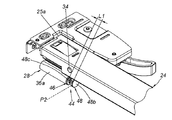
図1及び図2に示すように、本発明の一実施形態に係るスライドレールアセンブリ20は、第1のレール22と、第2のレール24と、ブロック構造26と、ベース28とを含む。加えて、スライドレールアセンブリ20はフィッティング部材をさらに含む。本実施形態では、フィッティング部材をブロック部材30として示している。
As shown in FIGS. 1 and 2, a
第1のレール22は、レール22aと、延長部22bと、垂直部22cとを有する。延長部22bは、レール22aと垂直部22cとの間に接続されている。ブロック構造26は、第1のレール22及び第2のレール24の一方に配置されている。以下では、ブロック構造26が第1のレール22の延長部22bに配置されている場合を一例として説明する。ブロック構造26は突起又はブロック壁であり得る。第1のレール22は前部23a及び後部23bをさらに有する。ブロック構造26は、第1のレール22の前部23aに隣接して配置され、レール22a、延長部22b及び垂直部22cによって囲まれる空間内に位置する。
The
第2のレール24は、第1のレール22に対して長手方向に移動可能である。スライドレールアセンブリ20は、第2のレール24と第1のレール22(のレール22a)との間に移動可能に取り付けられる第3のレール32をさらに含むことが好ましい。第3のレール32は第1のレール22に対する第2のレール24の移動距離を延ばすように構成されている。第2のレール24は前部25a及び後部25bを有する。図1に示すように、第2のレール24は第1のレール22に対して伸長位置Eに位置している。
The
ベース28は、第1のレール22及び第2のレール24のうちの他方に接続される。以下では、ベース28が第2のレール24に接続されている場合を一例として説明する。ベース28は、第2のレール24に固定接続することができる。あるいは、ベース28は第2のレール24に取り外し可能に接続することができる。ベース28が第2のレール24に接続されている場合、ベース28は第2のレール24の一部と見なされる。ベース28は、レール24の前部25aに接続されるとともに前部25aに隣接することが好ましい。ベース28は長手方向に沿って配置されるとともに、ベース28は接続部34及び複数の壁を含むことが好ましい。本実施形態では、複数の壁は第1の壁36a、第2の壁36b及び第3の壁36cである。接続部34は第1の壁36aに接続されている。第1の壁36a、第2の壁36b及び第3の壁36cは接続部34を通じて第2のレール24の側部38に接続されている。第1の壁36a、第2の壁36b及び第3の壁36cは互いに対して屈曲されている。第1の壁36a、第2の壁36b及び第3の壁36cによって空間Sが定義され、空間Sは、ブロック部材30が取り外し可能に取り付けられるように構成されている。第1の壁36a、第2の壁部36b、第3の壁部36cによって非円形の輪郭が形成され、空間Sは非円形の輪郭によって定義されることが好ましい。
The
ブロック部材30はベース28に取り外し可能に取り付けられる。例えば、ブロック部材30は、空間S内に取り付けられるように構成された第1の部分30aを含む。ブロック部材30は、第1の部分30aに接続される第2の部分30bをさらに含むことが好ましい。第2の部分30bの大きさは、第1の部分30aの大きさ及び空間Sの大きさよりも大きい。第1の部分30aが空間Sに取り付けられた場合、第2の部分30bはベース28の空間Sの外に位置する。ブロック部材30は、プラスチック材料又は弾性材料等の非金属材料でできていることが好ましい。
The
図3に示すように、スライドレールアセンブリ20は家具システムに適用可能である。家具システムは第1の家具部材40(キャビネット等)及び第2の家具部材42(引き出し等)を含む。第2の家具部材42は、前面板42aを有する。第1のレール22は第1の家具部材40に固定取り付けされ、第1の家具部材40の一部とみなすことができる。他方、第2のレール24は第2の家具部材42の底部を保持するように構成され、第2の家具部材42の一部とみなすことができる。第2のレール24が第1のレール22に対して伸長位置Eに位置する場合、ブロック部材30とブロック構造26との間に所定の距離がある。
As shown in FIG. 3, the
図3及び図4に示すように、第1の種類のユーザーの要望では、第2のレール24が第1のレール22に対して引っ込められている場合、ブロック部材30(フィッティング部材としても知られる)がベース28に取り付けられることで、第2のレール24が実質的に同じ位置に位置するようにできるか又は騒音を減らすことができる。
As shown in FIGS. 3 and 4, the first type of user desires that when the
具体的には、ブロック部材30がベース28に取り付けられ、第2のレール24が第1のレール22に対して伸長位置Eから方向Dに沿って引っ込められている場合(例えば、第2のレール24が第1のレール22に対して完全に引っ込められている場合)、ブロック部材30(第2の部分30b等)がブロック構造26に当接することを通じて第2のレール24を1つの所定の長手方向位置(即ち、1つの深さ位置)に位置するようにすることができる。本実施形態において、第2のレール24は、第1の長手方向位置P1に位置する。即ち、第2のレール24が伸長位置Eから方向Dに沿って第1のレール22に対して引っ込められている場合(例えば、第2のレール24が第1のレール22に対して完全に引っ込められている場合)、第2のレール24はブロック部材30(第2の部分30b等)がブロック構造26に当接することを通じて第1のレール22に対して第1の長手方向位置P1に実質的に位置することができる。ブロック部材30はプラスチック材料又は弾性材料でできているため、ブロック部材30は、ブロック部材30がブロック構造26に当接した場合(即ち、第2のレール24が第1のレール22に対して引っ込められ、第1の長手方向位置P1に位置する場合)に騒音を低減するか又は制動効果を提供できる。
Specifically, when the
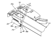
図5及び図6に示すように、第2の種類のユーザーの要望では、深さ調整が可能な家具システム又はスライドレールアセンブリ20が望ましいか又は第1のレール22(又は第1の家具部材40)と第2のレール24(又は第2の家具部材42)との間の許容誤差の問題を解消するための調節機構が望ましい。上記のフィッティング部材は、ベース28に選択的に取り付け可能な調節装置44であり得る。
As shown in FIGS. 5 and 6, a second type of user desires a depth adjustable furniture system or slide
具体的には、ブロック部材30が既にベース28に取り付けられている場合、先ず、ベース28からブロック部材30を取り外し、その後に調節装置44をベース28に取り付けることができる。即ち、上述した2つの種類の要望に応じて、ブロック部材30及び調節装置44のそれぞれをベース28に取り付けることができる。ブロック部材30及び調節装置44は同じ位置に取り付けられる。調節装置44は取り付け部材46及び調節部材48を含む。取り付け部材46及び調節部材48は互いに調整可能に接続される。例えば、取り付け部材46及び調節部材48とは互いにネジ留めされる。取り付け部材46はベース28の空間S内に収容されて取り付けられ、取り付け部材46は第1のネジ部50を有する。他方、調節部材48は本体部48aを含む。調節部材48は、本体部48aに接続される頭部48bをさらに含み、頭部48bの大きさは本体部48aの大きさよりも大きい。調節部材48が、第2のネジ部48cを通じて取り付け部材46の第1のネジ部50にネジ留めされている場合、頭部48bはベース28の空間Sの外に位置する。調節可能に取り付け部46に接続された調節部材48を通じて、調節装置44の長さ(長手方向の長さ)を調整できるように取り付け部材46に対する調節部材48の位置を調節することができる。なお、スライドレールアセンブリ20の他の関連部分の構成(例えば、第1のレール22、第2のレール24、ブロック構造26及びベース28の構成)は上述したため、それらに関する説明は簡略化のために省略する。
Specifically, when the
図6に示すように、ベース28は第2のレール24の前部25aに接続されるとともに前部25aに隣接する。調節部材48が取り付け部材46に対してまだ調節されていない場合、調節装置44はベース28を第1の長さL1伸長させる。その間、調節部材48は取り付け部材46に対して所定の位置に、例えば第2の長手方向位置P2に位置する。
As shown in FIG. 6, the
図7に示すように、調節部材48を取り付け部材46に対して時計回りに回転させると、調節装置44は、ベース28を第2の長さL2伸長するように調節される。その間、調節部材48は取り付け部材46に対して別の位置に、例えば第3の長手方向位置P3に位置する。
As shown in FIG. 7, when the adjusting
図8に示すように、調節部材48を取り付け部材46に対して反時計回りに回転させると、調節装置44はベース28を第3の長さL3伸長するように調節される。その間、調節部材48は取り付け部材46に対して別の位置に、例えば第4の長手方向位置P4に位置する。
As shown in FIG. 8, when the adjusting
第2の長手方向位置P2、第3の長手方向位置P3及び第4の長手方向位置P4は別々の位置であり、第1の長さL1、第2の長さL2及び第3の長さL3は別々の長さである。 The second longitudinal position P2, the third longitudinal position P3, and the fourth longitudinal position P4 are separate positions and have a first length L1, a second length L2, and a third length L3. Are separate lengths.
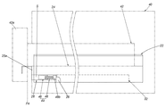
図9及び図10に示すように、調節装置44がベース28に取り付けられ、調節部材48が取り付け部材46又はベース28に対して調節されていない場合(図示しないが、例えばベース28が調節部材48に対応するネジ部を有することができる)、調節装置44は上述した第1の長さL1を有する。この状態において、第2のレール24が伸長位置Eから方向Dに沿って第1のレール22に対して引っ込められている場合(例えば第2のレール24が第1のレール22に対して完全に引っ込められている場合)、調節部材48の頭部48bは、第2のレール24が第1のレール22に対して長手方向位置に、例えば上述した第2の長手方向位置P2に位置するように(図10に示すように)ブロック構造26に当接する。
As shown in FIGS. 9 and 10, when the
図11に示すように、調節部材48が取り付け部材46又はベース28に対して調節されている場合、調節装置44は前述した第2の長さL2を有する。この状態において、第2のレール24が伸長位置Eから方向Dに沿って第1のレール22に対して引っ込められている場合(例えば、第2のレール24が第1のレール22に対して完全に引っ込められている場合)、調節部材48の頭部48bは、第2のレール24が第1のレール22に対して別の長手方向位置に、例えば第3の長手方向位置P3に位置するようにブロック構造26に当接する。
As shown in FIG. 11, when the
図12に示すように、調節部材48は、前述した第3の長さL3を有するように取り付け部材46又はベース28に対して調節される。この状態において、第2のレール24が伸長位置Eから方向Dに沿って第1のレール22に対して引っ込められている場合(例えば、第2のレール24が第1のレール22に対して完全に引っ込められている場合)、調節部材48の頭部48bは、第2のレール24が、第1のレール22に対してさらに別の長手方向位置に、例えば第4の長手方向位置P4に位置するようにブロック構造26に当接する。
As shown in FIG. 12, the adjusting
調節装置44の長さは調節可能であり、調節装置44はブロック構造26に当接可能であることが分かる。そのため、第2のレール24が第1のレール22に対して引っ込められた場合、第2のレール24は第1の長手方向位置P1、第2の長手方向位置P2、第3の長手方向位置P3及び第4の長手方向位置P4等の異なる長手方向位置(異なる深さ位置)に位置することができる。なお、第2の種類の要望において、調節装置44が所定の長さ(例えば、第1の長さL1)を有するように調節装置44の調節部材48が取り付け部材46に対してまだ調整されておらず、第2のレール24が伸長位置Eから方向Dに沿って第1のレール22に対して引っ込められている場合(例えば、第2のレール24が第1のレール22に対して完全に引っ込められている場合)、調節部材48の頭部48bは、第2のレール24が第1のレール22に対して同じ長手方向位置に、例えば第2の長手方向位置P2に位置するようにブロック構造26に当接する。即ち、第2のレール24が第1のレール22に対して引っ込められている場合に第2のレール24が第2のレール24とは異なる別の長手方向位置(例えば、第3の長手方向位置P3又は第4の長手方向位置P4)に位置することを可能にするためには調節部材48を調節する必要がある。
It can be seen that the length of the
したがって、本発明の実施形態は以下の特徴を含む。 Accordingly, embodiments of the present invention include the following features.
1)ユーザーはブロック部材30(取り付け部材)をスライドレールに取り付けて、該スライドレールが他のスライドレールに対して実質的に同じ位置に位置するようでき、さらにスライドレールと他のスライドレールとの間の衝撃の騒音を低減することができる。あるいは、ユーザーは、調節装置44(フィッティング部材)をスライドレールに取り付けて、調節装置44の長さの調節に対応してスライドレールが他のスライドレールに対して別の位置に位置することができるようにすることを選択できる。そのため、スライドレールアセンブリは異なる要望を満たすことができる。
1) The user can attach the block member 30 (attachment member) to the slide rail so that the slide rail is located at substantially the same position with respect to the other slide rails. It is possible to reduce the noise of the impact between the two. Alternatively, the user can attach the adjustment device 44 (fitting member) to the slide rail so that the slide rail is located at another position relative to the other slide rails in response to adjusting the length of the
2)家具システムの第2の家具部材42(又は第2のレール24)は、調節装置44の長さの調節及び調節装置44がブロック構造26に当接することに対応して第1の家具部材40(又は第1のレール22)に対して引っ込められている場合に異なる深さ位置に位置することができる。したがって、本発明の実施形態の簡素な構造及び構成は市場における特定の動作的な要求を満たす。
2) The second furniture member 42 (or the second rail 24) of the furniture system is adapted to adjust the length of the
当業者であれば、本発明の教示を維持しながら多くの変更及び改良が装置及び方法に加えられ得ることに容易に気付く。従って、上記の開示は、添付の請求項の範囲によってのみ限定されると解釈すべきである。 Those skilled in the art will readily observe that numerous modifications and improvements may be made to the devices and methods while retaining the teachings of the invention. Therefore, the above disclosure should be construed as limited only by the scope of the appended claims.
20 スライドレールアセンブリ
22 第1のレール
24 第2のレール
26 ブロック構造
28 ベース
30 ブロック部材
32 第3のレール
34 接続部
36a、36b、36c 壁
38 側部
40 第1の家具部材
42 第2の家具部材
44 調節装置
46 取り付け部材
48 調節部材
50 ネジ部
Claims (9)
前記第1のレールに対して長手方向に移動可能な第2のレールと、
前記第1のレール及び前記第2のレールのうちの一方に配置されるブロック構造と、
前記第1のレール及び前記第2のレールのうちの他方に接続されるベースであって、該ベースは複数種類のフィッティング部材を選択的に取り付け可能に構成されている、ベースと、
前記ベースに取り外し可能に取り付けられるとともに、前記ブロック構造に当接するように構成されたフィッティング部材と、
を含むスライドレールアセンブリであって、
前記第1のレール及び前記第2のレールのそれぞれは前部及び後部を含み、
前記ブロック構造は前記一方の前部及び後部の間に配置され、前記ベースは前記他方の前部に隣接するように前記他方に接続され、
前記フィッティング部材が前記第1のレール及び前記第2のレールのうちの前記他方に取り付けられ且つ前記第2のレールが前記第1のレールに対して引っ込められている場合、前記フィッティング部材が前記ブロック構造に当接することを通じて前記第2のレールは前記第1のレールに対して1つの所定の長手方向位置に又は複数の所定の長手方向位置に位置することができる、スライドレールアセンブリ。 A first rail;
A second rail movable longitudinally with respect to the first rail;
A block structure disposed on one of the first rail and the second rail;
A base connected to the other of the first rail and the second rail , wherein the base is configured to be capable of selectively attaching a plurality of types of fitting members;
A fitting member detachably attached to the base and configured to abut the block structure ;
A slide rail assembly comprising:
Each of the first rail and the second rail includes a front and a rear,
The block structure is disposed between the one front part and the rear part, and the base is connected to the other so as to be adjacent to the other front part;
When the fitting member is attached to the other of the first rail and the second rail and the second rail is retracted with respect to the first rail, the fitting member is A slide rail assembly, wherein the second rail may be located at one predetermined longitudinal position or a plurality of predetermined longitudinal positions with respect to the first rail through abutting a structure.
前記ブロック部材が前記ベースに取り付けられ且つ前記第2のレールが前記第1のレールに対して引っ込められている場合、前記ブロック部材が前記ブロック構造に当接することを通じて前記第2のレールは前記1つの所定の長手方向位置に位置することができ、前記ブロック部材は弾性材料でできている、請求項1に記載のスライドレールアセンブリ。 The fitting member is a block member,
When the block member is attached to the base and the second rail is retracted with respect to the first rail, the second rail is connected to the first rail through the abutment of the block member with the block structure. The slide rail assembly according to claim 1 , wherein the slide member can be located at one of two predetermined longitudinal positions, and the block member is made of a resilient material.
前記調節装置は取り付け部材及び調節部材を含み、該取り付け部材と該調節部材とは、前記調節装置の長さを調節することができるように互いに調節可能に接続され、
前記取り付け部材は前記ベースに取り付け可能であり、前記調節部材は前記第2のレールが前記第1のレールに対して引っ込められている場合に前記ブロック構造に当接する、請求項1に記載のスライドレールアセンブリ。 The fitting member is an adjusting device;
The adjusting device includes a mounting member and an adjusting member, the mounting member and the adjusting member being adjustably connected to each other so that a length of the adjusting device can be adjusted,
The slide of claim 1 , wherein the mounting member is mountable to the base, and wherein the adjustment member abuts the block structure when the second rail is retracted relative to the first rail. Rail assembly.
前記第2のレールが前記第1のレールに対して引っ込められている場合、前記調節装置は前記第2のレールが前記第1のレールに対して所定の長手方向位置に位置するように前記ブロック構造に当接し、
前記調節部材が前記取り付け部材に対して調節されている場合、前記調節装置は別の長さを有し、
前記第2のレールが前記第1のレールに対して引っ込められている場合、前記調節装置は前記第2のレールが前記第1のレールに対して別の長手方向位置に位置するように前記ブロック構造に当接する、請求項3に記載のスライドレールアセンブリ。 If the adjustment member has not yet been adjusted with respect to the mounting member, the adjustment device has a predetermined length;
When the second rail is retracted with respect to the first rail, the adjustment device adjusts the block so that the second rail is at a predetermined longitudinal position with respect to the first rail. Abuts the structure,
When the adjustment member is adjusted relative to the mounting member, the adjustment device has another length;
When the second rail is retracted with respect to the first rail, the adjustment device adjusts the block so that the second rail is at another longitudinal position with respect to the first rail. 4. The slide rail assembly of claim 3 , wherein the slide rail assembly abuts the structure.
前記複数の壁により空間が定義され、前記複数の壁により非円形の輪郭が形成され、前記フィッティング部材が取り外し可能に取り付けられるように構成されている、請求項1に記載のスライドレールアセンブリ。 The base includes a connection and a plurality of walls, the plurality of walls being connected to the other of the first rail and the second rail through the connection;
Wherein the plurality of walls space is defined, said plurality of non-circular contour by a wall is formed, the fitting member is adapted to be mounted removably, the slide rail assembly according to claim 1.
前記第1の家具部材に固定取り付けされる第1のレールと、
前記第2の家具部材を保持する第2のレールと、
前記第1のレール及び前記第2のレールのうちの一方に配置されるブロック構造と、
前記第1のレール及び前記第2のレールのうちの他方に接続されるベースであって、該ベースは複数種類のフィッティング部材を選択的に取り付け可能に構成されている、ベースと、
前記ベースに取り外し可能に取り付けられるとともに、前記ブロック構造に当接するように構成されたフィッティング部材と、
を含み、
前記第1のレール及び前記第2のレールのそれぞれは前部及び後部を含み、
前記ブロック構造は前記一方の前部及び後部の間に配置され、前記ベースは前記他方の前部に隣接するように前記他方に接続され、
前記フィッティング部材が前記第1のレール及び前記第2のレールのうちの前記他方に取り付けられ且つ前記第2の家具部材が前記第1の家具部材に対して引っ込められている場合、前記フィッティング部材が前記ブロック構造に当接することを通じて前記第2の家具部材は前記第1のレールに対して1つの所定の長手方向位置に又は複数の所定の長手方向位置に位置することができる、スライドレールアセンブリ。 A slide rail assembly applicable to a furniture system, the furniture system including a first furniture member and a second furniture member, wherein the first furniture member and the second furniture member pass through the slide rail assembly. Attached to each other, the slide rail assembly
A first rail fixedly attached to the first furniture member;
A second rail for holding the second furniture member;
A block structure disposed on one of the first rail and the second rail;
A base connected to the other of the first rail and the second rail , wherein the base is configured to be capable of selectively attaching a plurality of types of fitting members;
A fitting member detachably attached to the base and configured to abut the block structure ;
Including
Each of the first rail and the second rail includes a front and a rear,
The block structure is disposed between the one front part and the rear part, and the base is connected to the other so as to be adjacent to the other front part;
When the fitting member is attached to the other of the first rail and the second rail and the second furniture member is retracted with respect to the first furniture member, the fitting member is A slide rail assembly, wherein the second furniture member may be located at one predetermined longitudinal position or at a plurality of predetermined longitudinal positions with respect to the first rail through abutting the block structure.
前記第2のレールが前記第1のレールに対して引っ込められている場合、前記ブロック部材が前記ブロック構造に当接することを通じて前記第2のレールは前記1つの所定の長手方向位置に位置することができる、請求項7に記載のスライドレールアセンブリ。 The fitting member is a block member,
When the second rail is retracted with respect to the first rail, the second rail is located at the one predetermined longitudinal position through the contact of the block member with the block structure. The slide rail assembly according to claim 7 , wherein
前記調節装置は取り付け部材及び調節部材を含み、該取り付け部材と該調節部材とは調節可能に互いに接続され、
前記第2のレールが前記第1のレールに対して引っ込められている場合、前記調節部材は前記ブロック構造に当接する、請求項7に記載のスライドレールアセンブリ。 The fitting member is an adjusting device;
The adjustment device includes a mounting member and an adjustment member, the mounting member and the adjustment member being adjustably connected to each other,
The slide rail assembly according to claim 7 , wherein the adjustment member abuts the block structure when the second rail is retracted relative to the first rail.
Applications Claiming Priority (2)
| Application Number | Priority Date | Filing Date | Title |
|---|---|---|---|
| TW107106907 | 2018-02-27 | ||
| TW107106907A TWI694791B (en) | 2018-02-27 | 2018-02-27 | Slide rail assembly for a furniture |
Publications (2)
| Publication Number | Publication Date |
|---|---|
| JP2019146952A JP2019146952A (en) | 2019-09-05 |
| JP6674516B2 true JP6674516B2 (en) | 2020-04-01 |
Family
ID=63442573
Family Applications (1)
| Application Number | Title | Priority Date | Filing Date |
|---|---|---|---|
| JP2018172043A Active JP6674516B2 (en) | 2018-02-27 | 2018-09-14 | Slide rail assembly |
Country Status (4)
| Country | Link |
|---|---|
| US (1) | US10517396B2 (en) |
| EP (1) | EP3530147B1 (en) |
| JP (1) | JP6674516B2 (en) |
| TW (1) | TWI694791B (en) |
Families Citing this family (4)
| Publication number | Priority date | Publication date | Assignee | Title |
|---|---|---|---|---|
| DE102018108647A1 (en) * | 2018-04-11 | 2019-10-17 | Paul Hettich Gmbh & Co. Kg | Pull-out guide and drawer series |
| TWI670031B (en) * | 2018-09-27 | 2019-09-01 | 川湖科技股份有限公司 | Slide rail mechanism |
| DE102020101514A1 (en) | 2020-01-23 | 2021-07-29 | Paul Hettich Gmbh & Co. Kg | Drawer runners and furniture |
| CN112890475B (en) * | 2021-02-03 | 2022-06-14 | 博洛尼家居用品湖北有限公司 | Clamping block and drawer slide rail assembly |
Family Cites Families (29)
| Publication number | Priority date | Publication date | Assignee | Title |
|---|---|---|---|---|
| US3074766A (en) * | 1960-08-22 | 1963-01-22 | Jonathan Mfg Company | Shock resisting support for slide structure for drawers, shelves and the like |
| DE9310582U1 (en) * | 1993-07-15 | 1993-09-23 | Paul Hettich GmbH & Co, 32278 Kirchlengern | LOCKING DEVICE FOR DRAWERS OR THE LIKE |
| AU2003206613A1 (en) * | 2003-01-03 | 2004-07-29 | Zimmer, Gunther | Guide system comprising a pneumatic deceleration device |
| AT502943B1 (en) * | 2005-04-01 | 2011-07-15 | Blum Gmbh Julius | DAMPING DEVICE FOR MOVABLE FURNITURE PARTS |
| MY146313A (en) * | 2005-10-11 | 2012-07-31 | Harn Marketing Sdn Bhd | Sliding guide rail system for a drawer |
| AT10097U1 (en) * | 2007-04-30 | 2008-09-15 | Blum Gmbh Julius | SPRING BUFFER FOR A FURNITURE |
| KR20100099301A (en) * | 2008-01-22 | 2010-09-10 | 그라스 아메리카, 인크. | Universal damping mechanism |
| DE202008006909U1 (en) * | 2008-05-21 | 2008-07-31 | Lautenschläger, Horst | Damping device for furniture doors |
| AT506879B1 (en) | 2008-06-10 | 2011-07-15 | Blum Gmbh Julius | DEVICE FOR RELEASABLE DUPLICATION OF A DRAWER WITH A RAIL OF A DRAWER EXTRACTOR |
| ITMI20090157U1 (en) | 2009-05-13 | 2010-11-14 | Agostino Ferrari Spa | GUIDE WITH PUSH-PULL FOR FURNITURE |
| DE202009017319U1 (en) * | 2009-12-21 | 2011-05-05 | Grass Gmbh | Furniture and device for a furniture |
| AT509415B1 (en) * | 2010-02-03 | 2013-12-15 | Blum Gmbh Julius | Arrangement with a drawer and a pull-out guide for a drawer with at least two latching positions |
| US20120017414A1 (en) * | 2010-07-23 | 2012-01-26 | Cerniglia Anthony J | Cabinet drawer support system |
| DE202010013193U1 (en) | 2010-12-22 | 2012-03-26 | Paul Hettich Gmbh & Co. Kg | Opening and closing device for movable furniture parts and ejection device |
| US8876230B2 (en) * | 2011-09-24 | 2014-11-04 | Hardware Resources, Inc. | Durable drawer retainer apparatus and method of use |
| CN102871381B (en) * | 2012-10-11 | 2014-12-10 | 伍志勇 | Drawer adjusting device |
| DE202012012265U1 (en) | 2012-12-21 | 2014-03-24 | Grass Gmbh | Device for adjusting a furniture part accommodated in a furniture carcass, guide device for moving a movable furniture part and furniture with a device for adjusting a furniture part accommodated in a furniture carcass |
| US10149539B2 (en) * | 2013-11-22 | 2018-12-11 | Hardware Resources, Inc. | Undermount drawer slide position adjustment apparatus and method of use |
| AT515265B1 (en) | 2014-01-09 | 2018-07-15 | Blum Gmbh Julius | drawer |
| AT14476U1 (en) | 2014-02-13 | 2015-11-15 | Blum Gmbh Julius | Pull-out guide for a movable furniture part |
| CN104886952B (en) * | 2014-03-05 | 2017-06-23 | 川湖科技股份有限公司 | Self-closing sliding rail assembly with damping mechanism |
| KR101454917B1 (en) | 2014-07-25 | 2014-11-12 | 장근대 | Rail device of drawer |
| DE102015106852A1 (en) | 2015-05-04 | 2016-11-10 | Paul Hettich Gmbh & Co. Kg | Device and method for fixing a pushing element |
| TWI539917B (en) | 2015-11-12 | 2016-07-01 | 川湖科技股份有限公司 | Slide rail assembly |
| TWI572304B (en) * | 2016-03-31 | 2017-03-01 | 川湖科技股份有限公司 | Drive mechanism and method for furniture parts |
| DE102016113044A1 (en) | 2016-07-15 | 2018-01-18 | Paul Hettich Gmbh & Co. Kg | Drive device for a movable furniture part and method for opening and closing a movable furniture part |
| TWI616164B (en) * | 2017-03-07 | 2018-03-01 | 川湖科技股份有限公司 | Coupling mechanism and slide rail assembly for furniture part |
| TWI610640B (en) * | 2017-03-07 | 2018-01-11 | 川湖科技股份有限公司 | Coupling mechanism and slide rail assembly with cushion function |
| US10314396B2 (en) * | 2017-09-27 | 2019-06-11 | Nan Juen International Co., Ltd. | Quick detachable slide rail and drawer mounting structure |
-
2018
- 2018-02-27 TW TW107106907A patent/TWI694791B/en active
- 2018-07-17 US US16/036,958 patent/US10517396B2/en active Active
- 2018-08-29 EP EP18191393.0A patent/EP3530147B1/en active Active
- 2018-09-14 JP JP2018172043A patent/JP6674516B2/en active Active
Also Published As
| Publication number | Publication date |
|---|---|
| JP2019146952A (en) | 2019-09-05 |
| TWI694791B (en) | 2020-06-01 |
| TW201936088A (en) | 2019-09-16 |
| US10517396B2 (en) | 2019-12-31 |
| EP3530147A1 (en) | 2019-08-28 |
| US20190261773A1 (en) | 2019-08-29 |
| EP3530147B1 (en) | 2023-05-17 |
Similar Documents
| Publication | Publication Date | Title |
|---|---|---|
| JP6674516B2 (en) | Slide rail assembly | |
| EP3154320B1 (en) | Slide rail assembly and bracket device thereof | |
| JP6731013B2 (en) | Rack system and slide rail assembly thereof | |
| US20190216219A1 (en) | Furniture System and Slide Rail Assembly Thereof | |
| US10492610B2 (en) | Slide rail assembly | |
| JP6983935B2 (en) | Slide rail assembly | |
| JP2019005546A (en) | Bracket assembly for rack | |
| TW202015590A (en) | Slide rail assembly | |
| EP3251555B1 (en) | Drawer slide rail | |
| KR101695929B1 (en) | Wall mount for multi-display | |
| EP3829276A1 (en) | Slide rail mechanism | |
| CN110200423B (en) | Sliding rail assembly for furniture | |
| CN109874247B (en) | Support assembly for cabinet | |
| JP6771052B2 (en) | Slide rail mechanism | |
| TW202008923A (en) | Adjustment mechanism for slide rail assembly | |
| CN105813418B (en) | Electrical control cabinet | |
| CN110960011B (en) | Slide rail mechanism | |
| JP2021087757A (en) | Slide rail assembly and bracket device thereof | |
| EP4321053B1 (en) | Slide rail assembly | |
| CN104856471A (en) | Sliding rail installing mechanism | |
| CN112930069B (en) | Slide rail assembly and bracket device thereof | |
| CN109152265B (en) | Bracket assembly for cabinet | |
| CN113056151B (en) | Rack system and slide rail mechanism thereof | |
| US20220079337A1 (en) | Height adjustment system for sliding drawers | |
| US20190223314A1 (en) | Rack mounting system |
Legal Events
| Date | Code | Title | Description |
|---|---|---|---|
| A621 | Written request for application examination |
Free format text: JAPANESE INTERMEDIATE CODE: A621 Effective date: 20180914 |
|
| A977 | Report on retrieval |
Free format text: JAPANESE INTERMEDIATE CODE: A971007 Effective date: 20190806 |
|
| A131 | Notification of reasons for refusal |
Free format text: JAPANESE INTERMEDIATE CODE: A131 Effective date: 20190820 |
|
| A521 | Request for written amendment filed |
Free format text: JAPANESE INTERMEDIATE CODE: A523 Effective date: 20190911 |
|
| TRDD | Decision of grant or rejection written | ||
| A01 | Written decision to grant a patent or to grant a registration (utility model) |
Free format text: JAPANESE INTERMEDIATE CODE: A01 Effective date: 20200225 |
|
| A61 | First payment of annual fees (during grant procedure) |
Free format text: JAPANESE INTERMEDIATE CODE: A61 Effective date: 20200306 |
|
| R150 | Certificate of patent or registration of utility model |
Ref document number: 6674516 Country of ref document: JP Free format text: JAPANESE INTERMEDIATE CODE: R150 |
|
| R250 | Receipt of annual fees |
Free format text: JAPANESE INTERMEDIATE CODE: R250 |
|
| R250 | Receipt of annual fees |
Free format text: JAPANESE INTERMEDIATE CODE: R250 |